JP2008513964A - Supply of particulate material to the vaporization zone - Google Patents
Supply of particulate material to the vaporization zone Download PDFInfo
- Publication number
- JP2008513964A JP2008513964A JP2007532493A JP2007532493A JP2008513964A JP 2008513964 A JP2008513964 A JP 2008513964A JP 2007532493 A JP2007532493 A JP 2007532493A JP 2007532493 A JP2007532493 A JP 2007532493A JP 2008513964 A JP2008513964 A JP 2008513964A
- Authority
- JP
- Japan
- Prior art keywords
- particulate material
- container
- screw structure
- organic
- supply path
- Prior art date
- Legal status (The legal status is an assumption and is not a legal conclusion. Google has not performed a legal analysis and makes no representation as to the accuracy of the status listed.)
- Pending
Links
- 0 C*(*N(*)*)N Chemical compound C*(*N(*)*)N 0.000 description 2
Images


Classifications
-
- H—ELECTRICITY
- H05—ELECTRIC TECHNIQUES NOT OTHERWISE PROVIDED FOR
- H05B—ELECTRIC HEATING; ELECTRIC LIGHT SOURCES NOT OTHERWISE PROVIDED FOR; CIRCUIT ARRANGEMENTS FOR ELECTRIC LIGHT SOURCES, IN GENERAL
- H05B33/00—Electroluminescent light sources
- H05B33/10—Apparatus or processes specially adapted to the manufacture of electroluminescent light sources
-
- C—CHEMISTRY; METALLURGY
- C23—COATING METALLIC MATERIAL; COATING MATERIAL WITH METALLIC MATERIAL; CHEMICAL SURFACE TREATMENT; DIFFUSION TREATMENT OF METALLIC MATERIAL; COATING BY VACUUM EVAPORATION, BY SPUTTERING, BY ION IMPLANTATION OR BY CHEMICAL VAPOUR DEPOSITION, IN GENERAL; INHIBITING CORROSION OF METALLIC MATERIAL OR INCRUSTATION IN GENERAL
- C23C—COATING METALLIC MATERIAL; COATING MATERIAL WITH METALLIC MATERIAL; SURFACE TREATMENT OF METALLIC MATERIAL BY DIFFUSION INTO THE SURFACE, BY CHEMICAL CONVERSION OR SUBSTITUTION; COATING BY VACUUM EVAPORATION, BY SPUTTERING, BY ION IMPLANTATION OR BY CHEMICAL VAPOUR DEPOSITION, IN GENERAL
- C23C14/00—Coating by vacuum evaporation, by sputtering or by ion implantation of the coating forming material
- C23C14/22—Coating by vacuum evaporation, by sputtering or by ion implantation of the coating forming material characterised by the process of coating
- C23C14/24—Vacuum evaporation
- C23C14/246—Replenishment of source material
-
- C—CHEMISTRY; METALLURGY
- C23—COATING METALLIC MATERIAL; COATING MATERIAL WITH METALLIC MATERIAL; CHEMICAL SURFACE TREATMENT; DIFFUSION TREATMENT OF METALLIC MATERIAL; COATING BY VACUUM EVAPORATION, BY SPUTTERING, BY ION IMPLANTATION OR BY CHEMICAL VAPOUR DEPOSITION, IN GENERAL; INHIBITING CORROSION OF METALLIC MATERIAL OR INCRUSTATION IN GENERAL
- C23C—COATING METALLIC MATERIAL; COATING MATERIAL WITH METALLIC MATERIAL; SURFACE TREATMENT OF METALLIC MATERIAL BY DIFFUSION INTO THE SURFACE, BY CHEMICAL CONVERSION OR SUBSTITUTION; COATING BY VACUUM EVAPORATION, BY SPUTTERING, BY ION IMPLANTATION OR BY CHEMICAL VAPOUR DEPOSITION, IN GENERAL
- C23C14/00—Coating by vacuum evaporation, by sputtering or by ion implantation of the coating forming material
- C23C14/06—Coating by vacuum evaporation, by sputtering or by ion implantation of the coating forming material characterised by the coating material
- C23C14/12—Organic material
Abstract
粒子状材料を気化させて表面上に凝縮させることで層を形成する1つの方法では、ある量の粒子状材料を、その粒子状材料が自由に通過できるサイズの開口部を有する第1の容器に供給する。その粒子状材料は、開口部を通じてスクリュー構造の中に移される。そのスクリュー構造の少なくとも一部を回転させて粒子状材料を第1の容器から供給路に沿って気化ゾーンに移し、その気化ゾーンでその粒子状材料の少なくとも1つの成分を気化させて表面に供給することで層を形成する。スクリュー構造のサイズは、粒子状材料が開口部を自由に通過するのが容易になるように選択されている。 In one method of forming a layer by vaporizing and condensing particulate material onto a surface, a first container having an amount of particulate material through which the particulate material can freely pass. To supply. The particulate material is transferred into the screw structure through the opening. Rotate at least part of the screw structure to transfer particulate material from the first container along the supply path to the vaporization zone where the vaporization zone vaporizes at least one component of the particulate material and supplies it to the surface By doing so, a layer is formed. The size of the screw structure is chosen so that it is easy for the particulate material to pass freely through the opening.
Description
本発明は、粒子状材料の物理的な気相蒸着の分野に関する。 The present invention relates to the field of physical vapor deposition of particulate materials.
OLEDデバイスは、基板と、アノードと、有機化合物からなる正孔輸送層と、適切なドーパントを含む有機発光層と、有機電子輸送層と、カソードを備えている。OLEDデバイスが魅力的なのは、駆動電圧が低く、高輝度で、視角が広く、フル-カラーのフラット発光ディスプレイが可能だからである。Tangらは、この多層OLEDデバイスをアメリカ合衆国特許第4,769,292号と第4,885,211号に記載している。 The OLED device includes a substrate, an anode, a hole transport layer made of an organic compound, an organic light-emitting layer containing an appropriate dopant, an organic electron transport layer, and a cathode. OLED devices are attractive because of their low drive voltage, high brightness, wide viewing angle, and full-color flat light emitting displays. Tang et al. Described this multilayer OLED device in US Pat. Nos. 4,769,292 and 4,885,211.
真空環境中での物理的気相蒸着は、小分子OLEDデバイスで用いられているような有機材料の薄膜を堆積させる主要な方法である。このような方法はよく知られており、例えばBarrのアメリカ合衆国特許第2,447,789号とTanabeらのヨーロッパ特許第0 982 411号に記載されている。OLEDデバイスの製造に用いられる有機材料は、速度に依存した望ましい気化温度またはそれに近い温度に長時間にわたって維持したとき、分解することがしばしばある。感受性のある有機材料をより高温に曝露すると、分子構造が変化し、それに伴って材料の性質が変化する可能性がある。 Physical vapor deposition in a vacuum environment is the primary method for depositing thin films of organic materials such as those used in small molecule OLED devices. Such methods are well known and are described, for example, in Barr U.S. Pat. No. 2,447,789 and Tanabe et al. European Patent No. 0 982 411. Organic materials used in the manufacture of OLED devices often decompose when maintained at or near the desired vaporization temperature depending on the rate for an extended period of time. When sensitive organic materials are exposed to higher temperatures, the molecular structure can change, and the properties of the material can change accordingly.
このような材料の熱感受性という問題を解決するため、ほんの少量の有機材料を蒸発源に供給し、その少量をできるだけ少なく加熱するということが行なわれてきた。このようにすると、材料は、顕著な分解を引き起こす温度曝露閾値に到達する前に消費される。この方法の欠点は、ヒーターの温度に制約があるために利用できる気化速度が非常に小さいことと、蒸発源の中に存在する材料が少量であるために蒸発源の動作時間が非常に短いことである。従来技術では、蒸着チェンバーに通気口を設け、蒸発源を分解清掃し、蒸発源に材料を再装填し、蒸着チェンバーの中を再び真空にし、導入したばかりの有機材料を数時間にわたって脱ガスした後に操作を再開する必要がある。小さな蒸着速度と、蒸発源への頻繁な材料供給に時間のかかることが、OLED製造設備のスループットに関する実質的な制約となっている。 In order to solve the problem of heat sensitivity of such materials, it has been practiced to supply only a small amount of organic material to the evaporation source and to heat that small amount as little as possible. In this way, the material is consumed before reaching the temperature exposure threshold that causes significant degradation. The disadvantages of this method are that the vaporization rate available is very small due to the heater temperature limitation and the evaporation source operating time is very short due to the small amount of material present in the evaporation source. It is. In the prior art, the evaporation chamber was vented, the evaporation source was disassembled and cleaned, the evaporation source was reloaded with material, the inside of the evaporation chamber was evacuated again, and the newly introduced organic material was degassed for several hours. The operation needs to be resumed later. The low deposition rate and the time-consuming supply of materials to the evaporation source are substantial constraints on the throughput of the OLED manufacturing facility.
装填する有機材料全体をほぼ同じ温度に加熱することの二次的な結果として、追加の有機材料(例えばドーパント)をホスト材料と混合するのが実際的ではなくなる。ただし例外は、ドーパントが気化するときの挙動および蒸気圧が、ホスト材料が気化するときの挙動および蒸気圧と非常に近い場合である。一般に、気化するときの挙動および蒸気圧が両者で非常に近いことはないため、その結果として、従来の装置は、ホスト材料とドーパント材料を同時に堆積させるのに別々の蒸発源を必要とすることがしばしばある。 As a secondary result of heating the entire loaded organic material to about the same temperature, it becomes impractical to mix additional organic material (eg, dopant) with the host material. An exception is when the behavior and vapor pressure when the dopant is vaporized are very close to the behavior and vapor pressure when the host material is vaporized. In general, vaporization behavior and vapor pressure are not very close together, and as a result, conventional equipment requires separate evaporation sources to deposit the host and dopant materials simultaneously. There are often.
単一成分の蒸発源を用いることの1つの帰結は、1種類のホストと複数種類のドーパントを含む膜を形成するのに多数の蒸発源が必要とされることである。これらの蒸発源は隣り合わせに配置されるため、同時蒸着条件をほぼ満たそうとすると外側の蒸発源ほど中心に向けて傾けることになる。実際上は、異なる材料を同時に蒸着するのに用いられる直線配列の蒸発源の数は、3つまでに制限されてきた。この制約があるため、OLEDデバイスの構造が実質的に制限されていた。そのため真空蒸着チェンバーに必要なサイズが大きくなり、真空蒸着チェンバーに必要とされるコストが上昇し、システムの信頼性が低下する。 One consequence of using a single component evaporation source is that multiple evaporation sources are required to form a film containing one type of host and multiple types of dopants. Since these evaporation sources are arranged adjacent to each other, the outer evaporation source is inclined toward the center when trying to substantially satisfy the simultaneous vapor deposition conditions. In practice, the number of linear array evaporation sources used to deposit different materials simultaneously has been limited to three. This limitation has substantially limited the structure of OLED devices. This increases the size required for the vacuum deposition chamber, increases the cost required for the vacuum deposition chamber, and decreases the reliability of the system.
さらに、別々の蒸発源を使用すると、堆積される膜に勾配効果が生じる。すなわち、移動している基板に最も近い蒸発源内の材料がその基板に直接接する最初の膜において過剰になるのに対し、最後の蒸発源内の材料は、最終的な膜の表面において過剰になる。勾配のあるこの同時堆積は、単一の材料が複数ある蒸発源のそれぞれから気化する従来の蒸発源では不可避である。共同ホストを用いるときなどに堆積される膜に勾配があることは、両端部いずれかの蒸発源の寄与が中央の蒸発源からの寄与の数%を超える場合に特に明らかである。図1に、そのような従来の気化装置5の断面図を示してある。この気化装置5は、有機材料を気化させるために個別の3つの蒸発源6、7、8(共通に“加熱用ボート”と表記)を備えている。異なる蒸発源からの材料による蒸気の気柱9は均一であることが好ましいが、実際には端から端へと組成が変化するため、基板15のコーティングが不均一になる。
Furthermore, the use of separate evaporation sources creates a gradient effect on the deposited film. That is, the material in the evaporation source closest to the moving substrate becomes excess in the first film that is in direct contact with the substrate, while the material in the last evaporation source becomes excess at the surface of the final film. This co-deposition with a gradient is unavoidable with conventional evaporation sources where a single material evaporates from each of the evaporation sources. The gradient in the deposited film, such as when using a co-host, is particularly evident when the contribution of the evaporation source at either end exceeds more than a few percent of the contribution from the central evaporation source. FIG. 1 shows a cross-sectional view of such a
従来の蒸発源のさらに別の制約は、装填した有機材料が消費されるにつれて蒸気用マニホールドの形状が変化することである。この変化があるため、気化速度を一定に維持するにはヒーターの温度を変化させねばならない。実際、オリフィスから出てくる蒸気の気柱の全体的な形状は、蒸発源の内部における有機材料の厚さおよび分布の関数として変化することが観察されている。特に、材料を十分に装填した蒸発源の中での蒸気流に対するコンダクタンスが十分に小さくてその蒸発源の内部で不均一な気化による圧力勾配が維持されるときにそうなる。この場合、装填された材料が消費されるにつれてコンダクタンスが大きくなるため、圧力分布が、したがって気柱の全体的な形状が、改善される。 Yet another limitation of conventional evaporation sources is that the shape of the steam manifold changes as the loaded organic material is consumed. Because of this change, the heater temperature must be changed to keep the vaporization rate constant. Indeed, it has been observed that the overall shape of the vapor column coming out of the orifice varies as a function of the thickness and distribution of the organic material within the evaporation source. This is particularly the case when the conductance for the vapor flow in a sufficiently loaded evaporation source is sufficiently small to maintain a pressure gradient due to non-uniform vaporization within the evaporation source. In this case, the conductance increases as the loaded material is consumed, thus improving the pressure distribution and thus the overall shape of the air column.
本発明の1つの目的は、粒子状材料を容器から気化ゾーンに効率的に移動させる方法を提供することである。 One object of the present invention is to provide a method for efficiently transferring particulate material from a container to a vaporization zone.
この目的は、粒子状材料を気化させて表面上に凝縮させることで層を形成する方法であって、
(a)ある量の粒子状材料を、その粒子状材料が自由に通過できるサイズの開口部を有する第1の容器に供給し;
(b)上記開口部を通じてその粒子状材料をスクリュー構造の中に移し;
(c)そのスクリュー構造の少なくとも一部を回転させて上記粒子状材料を第1の容器から供給路に沿って気化ゾーンに移し、その気化ゾーンでその粒子状材料の少なくとも1つの成分を気化させて表面に供給することで層を形成する操作を含んでおり、
上記スクリュー構造のサイズが、上記粒子状材料が上記開口部を自由に通過するのが容易になるように選択されている方法によって達成される。
The purpose is to form a layer by vaporizing particulate material and condensing on the surface,
(A) supplying an amount of particulate material to a first container having an opening sized to allow the particulate material to freely pass through;
(B) transferring the particulate material into the screw structure through the opening;
(C) rotating at least a part of the screw structure to transfer the particulate material from the first container along the supply path to the vaporization zone and vaporizing at least one component of the particulate material in the vaporization zone; Including the step of forming a layer by supplying to the surface,
The size of the screw structure is achieved by a method that is selected to facilitate the passage of the particulate material freely through the opening.
従来のデバイスが動作している間は材料が連続的に加熱されるが、本発明ではそれがなくなり、粒子状材料の一部だけが、短時間、制御された速度で加熱されるというのが1つの利点である。粒子状材料の塊はある温度に維持されるが、その温度は、速度に依存した望ましい気化温度より300℃も低くすることができる。これは、有機材料を気化させるときに特に有利である可能性がある。 While the conventional device is in operation, the material is continuously heated, but in the present invention it is eliminated and only a portion of the particulate material is heated at a controlled rate for a short time. One advantage. The mass of particulate material is maintained at a certain temperature, which can be as much as 300 ° C. below the desired vaporization temperature depending on the rate. This can be particularly advantageous when vaporizing organic materials.
本発明のさらに別の利点は、ヒーターの温度を一定にして連続的に粒子状材料を補充しながら安定な気化速度を維持できることである。したがって本発明の装置により、温度に非常に敏感な有機材料でさえ、分解するリスクを実質的に小さくして蒸発源の動作時間を延ばすことができる。 Yet another advantage of the present invention is the ability to maintain a stable vaporization rate while continuously replenishing particulate material at a constant heater temperature. Thus, the apparatus of the present invention can extend the operating time of the evaporation source with substantially reduced risk of decomposition, even for organic materials that are very sensitive to temperature.
本発明のさらに別の利点は、気化速度と分解温度閾値が異なる複数の材料を同じ蒸発源の中で同時に昇華させられることである。 Yet another advantage of the present invention is that multiple materials with different vaporization rates and decomposition temperature thresholds can be sublimated simultaneously in the same evaporation source.
本発明のさらに別の利点は、圧縮した粒子状材料の計量供給速度または供給圧力を制御することにより、気化速度を制御して直線的にできることである。 Yet another advantage of the present invention is that the vaporization rate can be controlled and linearized by controlling the metered feed rate or feed pressure of the compressed particulate material.
本発明のさらに別の利点は、粒子状材料の計量供給速度を制御することにより、気化を迅速に停止させて再開させることと、安定な蒸着速度を素早く達成できることである。その結果、基板のコーティング中ではないときには、蒸着チェンバーの壁面の汚染が最少になり、粒子状材料が節約される。 Yet another advantage of the present invention is that by controlling the metering rate of the particulate material, vaporization can be quickly stopped and restarted, and a stable deposition rate can be achieved quickly. As a result, when the substrate is not being coated, contamination of the deposition chamber wall is minimized and particulate material is saved.
本発明のさらに別の利点は、この装置により、従来の装置よりも材料の分解を実質的に少なくして実質的に大きな蒸着速度が実現されることである。さらに、蒸発源の材料が消費されるにつれてヒーターの温度を変える必要がない。 Yet another advantage of the present invention is that this apparatus provides a substantially higher deposition rate with substantially less material degradation than conventional apparatus. Furthermore, it is not necessary to change the temperature of the heater as the source material is consumed.
本発明のさらに別の利点は、蒸発源を任意の方向に向けられることである。これは従来の装置では不可能なことがしばしばある。 Yet another advantage of the present invention is that the evaporation source can be directed in any direction. This is often not possible with conventional devices.
本発明のいくつかの実施態様のさらに別の利点は、従来よりもはるかに少量の材料がデバイスの中を運ばれるため、熱と真空を利用して粒子状材料から吸着したガスを除去できることである。 Yet another advantage of some embodiments of the present invention is that much smaller amounts of material are carried through the device than before so that heat and vacuum can be used to remove adsorbed gas from particulate material. is there.
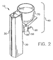
ここで図2を参照すると、有機粒子状材料を気化させて表面上に凝縮させることで層を形成するための本発明による装置の一実施態様の三次元図が示してある。気化装置10は、マニホールド20と、それに取り付けられた供給装置40を備えている。供給装置40は、第1の容器50と供給路60を少なくとも備えており、第2の容器70も備えることができる。第1の容器50には、ある量の第1の粒子状材料(例えば一実施態様では粉末)が供給される。明らかなように、第2の容器70は有機粒子状材料を収容することができ、それを第1の容器50に移すことができる。マニホールド20は1つ以上の開口部30を備えており、気化した粒子状材料がその開口部を通じて出ていき基板の表面に到達することができる。マニホールド20は鉛直方向を向いた基板上に層を形成できるように図示してあるが、この方向に限定されるわけではない。マニホールド20が水平方向を向いていて、水平な基板上に層を形成することもできる。マニホールド20は、譲受人に譲渡されたLongらによるアメリカ合衆国特許出願第10/784,585号に詳細に記載されている。供給装置40は、マニホールド20の底部、すなわち開口部30の反対側に取り付けた状態が図示してあるが、マニホールド20の同じ側に取り付けることもできる。マニホールド20への供給装置40の取り付け方は明らかであろう。
Referring now to FIG. 2, there is shown a three-dimensional view of one embodiment of an apparatus according to the present invention for forming a layer by vaporizing and condensing organic particulate material onto a surface. The
ここで図3を参照すると、本発明に従って粒子状材料を供給するための上記気化装置の一部に関する一実施態様の断面図が示してある。この気化装置によって有機材料が効果的に流動化されてスクリュー構造に移される。第1の容器50には有機粒子状材料160(細かく分割された粉末の形態であり、均一なサイズであることが望ましい)が収容されており、その有機粒子状材料は供給路60のスクリュー構造80に供給される。スクリュー構造80は第1の容器50の内部を貫通しており、上記のマニホールド(図を見やすくするため図示していない)の中へと通じている。スクリュー構造80の少なくとも一部がモータ90によって回転され、有機粒子状材料が供給路60に沿って制御された体積速度または圧力で気化ゾーンに移される。その有機材料は気化ゾーンで気化した後、基板に供給されて層を形成する。供給路60、したがって供給路60に流入する有機粒子状材料160は、その有機材料の望ましい気化温度よりも低い温度に維持することができる。有機粒子状材料160がスクリュー構造80へ移動しやすくするため、振動装置(例えばピエゾ電気構造130または電気機械式バイブレータ)を用いて有機粒子状材料160を振動させることによって流動化する。このように流動化した材料は、重力を利用した供給によってスクリュー構造80へとより容易に移動する。
Referring now to FIG. 3, there is shown a cross-sectional view of one embodiment for a portion of the vaporizer described above for supplying particulate material in accordance with the present invention. This vaporizer effectively fluidizes the organic material and transfers it to the screw structure. The
追加の有機粒子状材料100を収容するための補助の第2の容器70があると、利点がいくつか追加される。大量の有機粒子状材料100を装置に装填できるため、より長時間にわたって装置を連続的に動作させることが可能になる。第1の容器50内の有機粒子状材料160の量を検知することにより(例えば柱状の有機粒子状材料160の高さを測定することにより)、第2の容器70から第1の容器50へと移される有機粒子状材料100の量を選択的に計量し、第1の容器50に実質的に一定体積(例えば±5cm3)の有機粒子状材料160を供給することができる。実際には、10cm3の有機粒子状材料160が第1の容器50に装填される。この明細書に記載したいくつかの実施態様では、容器内の材料の高さが広い範囲にわたっているときに有機粒子状材料160を信頼性よく供給することに関するゆとりが大きいため、ほぼ完全に追加の有機粒子状材料160を排出させて供給に失敗することがないようにできる。しかし多成分の混合の一様性は、第1の容器50内における材料の高さが最適にされていてその高さが±10%以内に維持される場合に促進される。このようにすると有機粒子状材料160を供給路60に供給する速度の変化が最少になる。また、第2の容器70は、第1の容器50の動作に影響を与えることなく再充填できる構成にすることができる。そのためより長時間にわたって装置を連続的に動作させることが可能になる。有機粒子状材料100は、例えばスクリーン110と120によって第2の容器70の中に保持される。スクリーンのサイズは、粒子状材料が自由に流れることがないように選択する。スクリーン110と120は、計量された量の有機粒子状材料100を第2の容器70から第1の容器50へと移動させる機構にすることもできる。スクリーン110と120は、ある量の有機粒子状材料100がスクリーンのメッシュを通過するようにできる振動装置(図示せず)によって接触させることができる。そのような振動装置としては、スクリーンを振動させる装置や、スクリーン110と120を選択的に撹拌できるようにするためにスクリーンの直上または直下に位置する移動可能なアームが挙げられる。市販の小麦粉シフターは、この用途で用いるのによく適した1つの装置である。このシフターでは、3つのスクリーンが用いられていて、各スクリーンの上面が、シフターの中心から放射状に延びる回転可能なアームによって接触状態にされている。アームはV字形の断面を持っているため、粉末化した有機粒子状材料100は、アームが回転するにつれ、アームとスクリーンに挟まれた先細の空間へと強制的に送られ、制御された体積の有機粒子状材料100の粉末がスクリーンを通過する。第1の容器50内の有機粒子状材料160の高さ(または堆積速度と動作時間から得られる積分信号)の検知システムがスクリーン110と120を振動させる装置を作動させ、第1の容器50内の有機粒子状材料160の粉末の体積をほぼ一定に維持することができる。振動装置(例えばピエゾ電気構造140)は、第1の容器50への供給路に有機粒子状材料100が蓄積しないようにする。ピエゾ電気構造をいろいろな振動数で振動させ(例えばサイレン効果)、振動の節に有機粒子状材料100が蓄積しないようにすることができる。
The presence of an auxiliary
供給装置40が適切に動作するためには、有機粒子状材料160の供給速度が一定に維持されることが重要である。有機粒子状材料160は一般に粉末化された形態で供給される。自由に流れる有機粒子状材料160を供給するための重要な1つの方法は、架橋状態にならないようにすることである。架橋は、粉末などの粒子状材料の特徴的な挙動であり、粉末化した粒子が自己凝集して開口部の周囲に負荷をかける構造ができることによって粉末が開口部を通過するのを妨げるときに起こる可能性がある。架橋効果は、例えば開口部のサイズが小さすぎて粒子状材料が流れようとするのが妨げられる場合に起こる可能性がある。架橋を引き起こす可能性のある因子として、開口部のサイズに対する粒子のサイズ、湿度、粒子間の静電引力、真空のレベル、摩擦などがある。この問題を解決するには、例えば図3に示したように、第1の容器50と供給路60のインターフェイスにおける開口部230のサイズを、粉末化した材料の架橋特性に打ち勝つのに十分なサイズにする必要がある。サイズに関するこの条件を決めるにあたり、有機粒子状材料160は自由に流れる状態で供給路60に供給されねばならないため、そのための最悪の条件を考慮して経験的に決定するのが最良である。第1の容器50内にほぼ一定体積の有機粒子状材料160を維持すると、有機粒子状材料160をスクリュー構造80に一定速度で供給するのが容易になる。開口部230を適切なサイズにし、第1の容器50内に十分な体積の有機粒子状材料160があるようにすることで、粉末化した多くのタイプの有機粒子状材料160に関して一定の供給速度を維持し、いかなる新たな形態の振動も必要とすることなく流動化した流れを提供することができる。
In order for the
開口部230が狭くなければならない場合には、一定の供給速度は、スクリューの供給部分の近くにある有機粒子状材料160が振動装置によって流動状態に維持されるときに保証される。これは、スクリューの直上にある有機粒子状材料160をゆっくりと振動させることによって、または例えばピエゾ電気構造130によって有機粒子状材料160に振動を誘導することによって実現できる。その結果、粉末化した有機粒子状材料160が液体のような挙動をするようになるが、ガスのような挙動をするようになるほどエネルギーは大きくない。
If the
ここで図4を参照すると、本発明に従って有機粒子状材料160を供給して気化させるための上記装置の一部の一実施態様に関するさらに詳細な断面図が示してある。スクリュー構造80が有機粒子状材料160の粉末を供給路60に沿ってマニホールド20および加熱素子170へと移動させる。加熱素子170は、例えば加熱されたスクリーンにすることができ、Longらによって以前に詳細に記載されている。マニホールド20は、供給路60のうちで加熱素子170に隣接する領域として定義される気化ゾーンを備えている。有機粒子状材料160の粉末の薄い断面が、接触と熱伝導により、速度に依存した望ましい温度(加熱素子170の温度)に加熱され、有機粒子状材料160の粉末のその薄い断面が気化し、基板の表面に供給されて層を形成する。スクリュー構造80とその回転速度が、有機粒子状材料160が加熱素子170に供給される速度を規定する。気化速度は制御されて直線的になるため、有機粒子状材料160が蒸気の状態でマニホールドから出ていく速度も直線的になる。したがって有機粒子状材料160をスクリュー構造80と気化ゾーンに供給する速度が、気化した成分を望む表面に堆積させる速度を規定する。
Referring now to FIG. 4, there is shown a more detailed cross-sectional view of one embodiment of a portion of the above apparatus for supplying and vaporizing organic
さらに、基部180を備えることができる。基部180は熱散逸構造であり、加熱素子170からの熱の多くが供給路60に沿って移動するのを妨げることで、有機粒子状材料160の塊を、加熱素子170に隣接した気化ゾーンで感じるよりも有意に冷たい状態に維持する。基部180のための熱散逸手段は、譲受人に譲渡されたLongらによる上記のアメリカ合衆国特許出願第10/784,585号に記載されている。このようにして生み出される急な熱勾配により、気化している材料に隣接している部分以外のすべての部分が高温から保護される。気化した有機蒸気は加熱素子170を素早く通過し、加熱されたマニホールド20に入ることができる。望ましい気化温度になっている有機粒子状材料160の滞在時間は非常に短いため、熱分解が非常に少なくなる。有機粒子状材料160が高温、すなわち速度に依存した気化温度になっている時間は、従来の装置および方法よりも数桁短い(従来の数時間から数日に対して数秒)。そのため有機粒子状材料160を従来よりも高温に加熱することができる。したがって本発明の装置と方法により、有機粒子状材料160の有機成分を大量に分解させることなく、実質的により大きな気化速度を実現することができる。
Furthermore, a base 180 can be provided. The
有機粒子状材料160は、単一の成分でもよく、気化可能な2種類以上の異なった成分(例えば気化温度がそれぞれ異なる複数の有機成分)を含んでいてもよい。気化温度はさまざまな手段で測定することができる。例えば図5は、OLEDデバイスで一般に使用される2種類の有機材料に関して蒸気圧と温度の関係を示したグラフである。気化速度は蒸気圧に比例するため、望ましい気化速度に関し、図5を利用してその望む気化速度に対応する必要な加熱温度を決めることができる。粒子状材料160が2種類以上の有機成分を含んでいる場合には、加熱素子170の温度は、気化が供給速度によって制限されるように選択する。すなわち加熱素子の温度での蒸気圧が実質的にマニホールド内のその成分の望ましい部分圧よりも大きくなるように選択する。したがって有機成分のそれぞれが同時に気化する。
The organic
気化が進むにつれてマニホールド20内の圧力が上昇し、気流がマニホールド20から図2に示した一連の開口部30を通じて出ていく。有機粒子状材料160のほんの一部(気化ゾーンに存在している部分)しか速度に依存した気化温度に加熱されず、材料の大部分は気化温度よりもはるかに低い温度に維持されているため、加熱素子170の位置にある加熱中断手段(例えばスクリュー構造80の運動を停止させる手段)によって気化を中断することが可能である。こうすることにより、基板表面のコーティング中ではないときに有機粒子状材料160を節約し、関連するあらゆる装置(例えば蒸着チェンバーの壁面)の汚染を最小にすることが可能になる。これについて以下に説明する。
As the vaporization progresses, the pressure in the manifold 20 increases, and the airflow exits the manifold 20 through the series of
加熱素子170は、粉末や圧縮された材料が自由に通過することを阻止する細かいメッシュ・スクリーンにできるため、マニホールドは任意の方向を向けて使用することができる。例えば図2のマニホールド20を下に向け、その下に位置する基板のコーティングを行なうことができる。これは、従来の加熱ボートでは見られない1つの利点である。
The
ここで図6Aを参照すると、本発明において有用なスクリュー構造の一実施態様の断面図が示してある。スクリュー構造80は、モータ90によって回転するスクリュー85を備えている。このスクリューの螺旋のネジ山の間の距離とネジ山の高さを選択する際には、有機粒子状材料160の粉末が詰まることも、螺旋とともに回転することもなく、水平方向を向いたスクリュー収容チューブの底部に留まり、スクリュー85とスクリュー収容チューブの相対運動によって直線的に運ばれるように決める。例えばスクリュー85のピッチが2.5mmでネジ山の高さが0.8mmであるスクリューが、有機粒子状材料160の粉末を水平方向に移動させるとともに一体化するのに効果的であることがわかった。
Referring now to FIG. 6A, a cross-sectional view of one embodiment of a screw structure useful in the present invention is shown. The
本発明の発明者は、一定の流速を維持するのにスクリュー構造のサイズが影響を与えることを見いだした。開口部230のサイズに関して上に指摘した架橋効果と同様、スクリュー構造の適切なサイズとスクリューの適切なピッチは、有機粒子状材料160の具体的な組成に関する最悪の状態を考慮して経験的に決定するのが最も好ましい。
The inventors of the present invention have found that the size of the screw structure has an effect on maintaining a constant flow rate. Similar to the cross-linking effect noted above with respect to the size of the
本発明の発明者は、スクリューのネジ山の角度を最適化すると有機粒子状材料160が供給路60に沿って自由に流れやすくできることも見いだした。スクリューのネジ山の最適な角度は粉末化した有機粒子状材料160の個々の成分によっていくらか異なる可能性があるが、スクリューのネジ山の角度がスクリュー構造85の回転軸に対して約4°〜約15°の範囲だと、通常用いられる有機粒子状材料160に関する最適な流動状態になることがわかった。
The inventor of the present invention has also found that the organic
さまざまな材料のスクリューのシャフトやさまざまに表面処理したスクリューのシャフトによってスクリューの操作が容易になり、供給速度を大きくできることがわかった。ステンレス鋼は許容できる性能だが、表面処理(例えば電気研磨)またはコーティング(例えば窒化チタン・コーティング)によってさらなる利点が得られる。 It was found that screw shafts of various materials and screw shafts with various surface treatments facilitate screw operation and increase the feeding speed. Stainless steel is an acceptable performance, but additional advantages are gained by surface treatment (eg, electropolishing) or coating (eg, titanium nitride coating).
スクリューの一定速度での連続的な回転によって許容できるレベルの性能が得られるが、パルス化によってスクリューのシャフトを繰り返して増分方式で回転させることにより、さらなる利点が得られる。パルス作用によってスクリューと粒子状材料の間の実質的な摩擦係数が小さくなるため、粉末化した有機粒子状材料160がスクリューと一体化して回転する傾向が少なくなる。したがってスクリュー構造80の粉末供給効率が向上する。パルス式の挙動は、例えばある時間の間に供給速度を変化させることが有用な場合にも有利である可能性がある。
While continuous rotation of the screw at a constant speed provides an acceptable level of performance, additional advantages are gained by repeatedly rotating the screw shaft in increments by pulsing. Since the substantial friction coefficient between the screw and the particulate material is reduced by the pulse action, the tendency of the powdered organic
有機粒子状材料160は、水平方向にはスクリュー85の底部に沿って転がりながら分散された形態で移動する。スクリュー85の端部では粉末の圧力が1MPaになる可能性があるため、有機粒子状材料160のバルクの密度は蒸気シールとして機能するほどの大きさになる。そのためマニホールド内で気化して周囲の真空レベルよりも大きな圧力になった材料がスクリューに沿って逆流して第1の容器50の位置にある供給源に到達することが阻止される。図6Bに示してあるように、スクリュー85の端部は、わずかな長さにわたって一定の円形断面を有する山なし部分135となるように構成されていて、一体化した有機粒子状材料160の粉末が狭い環状形状またはチューブ形状を形成する。この狭い環状形状により、温度制御されたスクリュー85と温度制御された供給路60の間の熱接触と有機粒子状材料160全体の温度の一様性が改善される。この構成によりさらに、円形断面と比較して所定の横断面における有機粒子状材料160の温度の一様性が保証され、スクリュー構造80と加熱素子170の間にある有機粒子状材料160内に温度勾配を実現できる可能性が実質的に大きくなる。粉末化した有機粒子状材料160はスクリュー構造からチューブの形状で押し出されて十分に一体化しているため、スクリュー収容チューブの支持体から出たときに押し出されたチューブ状の形状を少なくとも数ミリメートルにわたって維持することができる。この固体形状により、有機材料の気化によって生じる加圧された蒸気がスクリュー構造80に逆流することが阻止され、粉末化した有機粒子状材料160が、温度制御されたスクリュー構造の端部と加熱素子の間の短いギャップに架橋することが可能になる。
The organic
この環状構造を有する粉末供給システムの熱モデルにおいて加熱素子がスクリュー構造80の端部から130μm離れているとすると、有機粒子状材料160の加熱素子170とスクリュー構造80の端部にまたがる部分で、両者の温度差が270℃である場合に軸方向の平均温度勾配0.5℃/μmを実現できることがわかる。したがって粉末が一体化した有機粒子状材料160の最初の200μmで100℃の温度低下が可能である。この勾配により、混合成分有機材料の塊からより揮発性のある成分が染み出すことが阻止され、単一の供給源から複数の有機材料を同時に堆積させることが可能になる。さらに、この大きな勾配は、気化する前に液化する有機材料を用いる場合でさえ、有機粒子状材料160をスクリュー収容チューブの出口で一体化した粉末形状に維持するのに役立つ。
In the thermal model of the powder supply system having this annular structure, if the heating element is 130 μm away from the end of the
図6Aに示したスクリュー構造80は、有機粒子状材料160の粉末を水平方向に移動させるのに有効だが、有機粒子状材料160を鉛直方向に移動させるには有効でない。なぜなら、有機粒子状材料160の粉末はスクリューとともに回転するだけでこの構造の長さ方向に沿って進むことはないからである。ここで図6Cを参照すると、本発明において有用なスクリュー構造の別の一実施態様の立体図が示してある。この実施態様では、スクリュー構造95は、互いに噛み合った同じ螺旋状のネジ山を持つ2つ以上のスクリュー(例えばスクリュー85a、85b、85c)を備えている。これらスクリュー85a、85b、85cはすべて同じ方向に回転する。1つのスクリュー(例えば85a)のネジ山の間に装填された有機材料は、その材料が回転して回転している第2のスクリュー(例えば85b)の噛み合ったネジ山と接触すると除去される。なぜなら隣のスクリューの向かい合っている部分は反対方向に運動するからである。したがってスクリュー構造95では、粉末化した有機粒子状材料160を一体化して固体形状にすることで蒸気シールを形成する能力を保持しつつ、図6Aに示した単一スクリューのスクリュー構造の方向に関する制約が解決される。スクリュー構造95の排出部分は細長い断面を持つ可能性があろう。マニホールドの全長にわたってこの断面にできるため、材料を長さ方向に沿って実質的に一様に注入することが可能になる。
The
ここで図6Dを参照すると、本発明において有用なスクリュー構造の別の一実施態様の断面図が示してある。スクリュー構造105は、回転する螺旋状のネジ山115と、静止した中心部125と、静止した外側チューブ(ここでは供給路60)を備えている。この実施態様では、スクリュー構造105の一部だけ(螺旋状のネジ山115を含む部分)が回転可能であり、モータ90によって回転させられる。円形断面の螺旋状のネジ山を用いて供給される粉末化した有機粒子状材料160に関して検証を行なった。ネジ山は、直径が0.7mmの鋼鉄ワイヤを外径が5mmでピッチが2.5mmの螺旋にしたものからなる。他の材料(例えばチタンやステンレス鋼)からなる滑らかなワイヤも適している。ワイヤの断面は円形でなくてもよく、長方形の断面が特に好ましい。というのも、粉末化した有機粒子状材料160を押している間にねじり抵抗を受けるとき、螺旋状のネジ山のサイズが変化しないようにするだけの剛性が付加されるからである。静止した中心部125は、供給路60と組み合わさり、粉末化した有機粒子状材料160の薄膜以外がスクリューとともに回転することを実質的に阻止する。スクリュー構造105は、粉末化した有機粒子状材料160を蓄積するのに重力に頼っておらず、任意の方向で動作する。スクリュー構造105は、粉末化した有機粒子状材料160を一体化して薄い環状形状にする。そのため有機粒子状材料160と温度制御された供給路60と静止した中心部125の間の熱接触が実質的に改善される。これらの特性は、混合成分有機材料の気化と、気化する前に液化する有機材料の気化を制御できるようにする上で重要である。したがってこの実施態様により、粉末化した有機粒子状材料160を一体化して固体形状にすることで蒸気シールを形成する能力を保持しつつ、第1のスクリュー構造における方向に関する制約が解決される。
Referring now to FIG. 6D, a cross-sectional view of another embodiment of a screw structure useful in the present invention is shown. The
主に図2の気化装置10をベースとした本発明による上記の実施態様は、大気圧においてと、大気圧の約半分までの圧力において有用である。実験によれば、細かい粉末は、大気圧の半分以下にした減圧下では計量がはるかに難しいことが観察されている。粉末化した有機粒子状材料160は、残留している空気の分子が除去されていくにつれて凝集し、大気圧の条件下では粉末化した有機粒子状材料160を通じて振動エネルギーを伝達するのに有効な粒子間の弾性カップリングが少なくなる。この効果は、スクリュー構造が粉末を一様に供給する性能にマイナスの影響を与える。したがって別の振動装置が必要となる可能性がある。ここで図7を参照すると、低圧条件下で上記の制約を解決する上で本発明において有用な振動装置の別の一実施態様の一部を除去して内部を示した図が示してある。この実施態様では、振動装置として3つのピエゾ電気構造が用いられている。ピエゾ電気構造150と155は大きく傾いていて、第1の容器50の底部において漏斗の対向する壁面を形成している。この2つのピエゾ電気構造の底部190は支持されておらず、スクリュー構造80の供給部に直接通じている。ピエゾ電気構造150、155の支持されていない部分は振動の振幅が大きいため、その部分の表面近くで有機粒子状材料160の粉末を流動化するのに有効である。第3のピエゾ電気構造130がスクリュー構造80の下に取り付けられていて、他の2つのピエゾ電気構造150、155の振動とは振幅が実質的に垂直な振動を与える。これらのピエゾ電気構造は、周波数掃引回路によって駆動される。振動数を変化させることはノードが形成されるのを阻止する上で重要であり、電力供給効率を大きく改善する。スクリュー構造80としては、上記のスクリュー構造のうちの任意のものが可能である。
The above-described embodiment according to the present invention, mainly based on the
図8は、低圧条件下で上記の制約を解決する上で本発明において有用な振動装置の別の一実施態様の一部を除去して内部を示した図である。上記第1の容器50の下端部に開口部230が来る。回転する螺旋式装置210は、共通するシャフトの周囲に左巻き螺旋ワイヤと右巻き螺旋ワイヤを備えている。回転する螺旋式装置210は、スクリュー構造の供給部の上方に位置していて、ワイヤがスクリュー構造80のネジ山に実質的に接している。回転するネジ山は、スクリューのネジ山の邪魔になってはならないが、1mmのクリアランスまで効果的に動作し続けるであろう。回転する螺旋式装置210は、モータ90によってギア・ドライブ220を通じてゆっくりと回転する。モータは、スクリュー構造80も回転させる。実際には、回転する螺旋式装置210の回転速度は、個々の有機粒子状材料160の粉末の粒径と特性によって異なる可能性があるが、実際的な目安として、回転するネジ山の軸方向回転速度をスクリューのネジ山の軸方向回転速度と一致させる。回転する螺旋式装置210のワイヤは、有機粒子状材料160の粉末を開口部230の中心へと押しやる傾向があるため、スクリュー構造80への粉末の架橋が防止される。スクリュー構造80としては、上記のスクリュー構造のうちの任意のものが可能である。この振動装置は、有機粒子状材料160の粉末にほんのわずかなエネルギーしか与えず、したがってサイズまたは密度によって粒子が分離することはないため、混合成分有機材料を供給するのに非常に適している。
FIG. 8 is a diagram showing the inside of a part of another embodiment of the vibration device useful in the present invention for solving the above-described restrictions under low pressure conditions. An
図9は、有機材料160の粉末を気化させて表面上に凝縮させることで膜を形成するための本発明による装置の別の一実施態様の一部に関する三次元図であり、有機粒子状材料160をあらかじめ処理して吸着したガスまたは不純物を除去する装置が含まれている。この装置は、ある量の有機粒子状材料160を保持する上記の第1の容器50を備えている。この装置は、第1の容器50に供給できるリザーブ用のある量の有機粒子状材料100を収容するための第2の容器70も備えることができる。この装置は、有機粒子状材料100を第2の容器70から第1の容器50に容易に移動させるための振動装置(例えばピエゾ電気構造140)も備えることができる。第1の容器50からの有機粒子状材料160は、あらかじめ処理するために第1の供給路260に供給される。第1の供給路260は、有機粒子状材料160を第1の容器50から第1の供給路260に移すため、第1の容器50に取り付けるスクリュー構造を備えている。このスクリュー構造の少なくとも一部がモータ240によって回転させられて有機粒子状材料160の粉末が第1の供給路260に沿って供給される。第1の供給路260は、真空に曝露するため減圧源に通じる開口部270を備えている。あるいは第1の供給路260を加熱して有機粒子状材料160の粉末を加熱する一方で、有機粒子状材料160を減圧状態にし、有機粒子状材料160が第1の供給路260に沿って移動するにつれて吸着したガスまたは不純物が除去され、あらかじめ処理された有機粒子状材料160として気化ゾーンに供給されるようにすることもできる。典型的な蒸着速度では、このあらかじめ処理する段階において、自由状態の有機粒子状材料160の粉末には、圧縮して気化させる直前に、吸着された水蒸気とガス分子を解放する時間が数分間ある。次に、あらかじめ処理した有機粒子状材料160の粉末は、上記のようにスクリュー構造によって規定された第2の供給路265に移されてその中で一体化される。すなわち圧縮され、スクリュー構造のまわりに一様に分配される。有機粒子状材料160の粉末は上記のようにスクリュー構造によって第2の供給路265に沿ってマニホールドと気化ゾーン(図示せず)に供給され、そこで有機材料が気化した後、OLED基板の表面に凝縮して有機層を形成する。補助の第3の容器250が第1の供給路260から真空に曝露された有機粒子状材料160の粉末を受け取ることができる。この場合、第2の供給路265を規定するスクリュー構造は第3の容器250にも取り付けられていて、真空に曝露された有機粒子状材料160の粉末を第2の供給路265に供給する。このスクリュー構造は、第3の容器250の内部を貫通している。この装置は、すでに説明したように、有機粒子状材料160の粉末を流動化する手段も備えている。別の一実施態様では、供給路260は、真空に曝露するための開口部270を備えており、第2の供給路なしにマニホールドに直接つながっている。
FIG. 9 is a three-dimensional view of a portion of another embodiment of an apparatus according to the present invention for forming a film by vaporizing and condensing a powder of
実際には気化装置は以下のように動作する。OLEDデバイスに層を形成するのに役立つ有機粒子状材料160の粉末が第2の容器70に供給される。この有機粒子状材料160は制御された状態で第1の容器50に移されるが、そのとき、第1の容器に存在する有機粒子状材料160の粉末の体積が実質的に同じである状態が維持されるようにする。有機粒子状材料160の粉末は、この明細書に記載した手段によって流動化し、スクリュー構造80に移すことができる。スクリュー構造は、この明細書に記載したようにして有機粒子状材料160の粉末を気化ゾーンに移す。有機粒子状材料160が気化ゾーンで気化し、マニホールド20に入る。マニホールドは、気化した有機材料をOLEDの基板の表面に送って層を形成する。このことに関して以下に説明する。
In practice, the vaporizer operates as follows. A powder of organic
すでに指摘したように、真空レベルが、一定量の細かい粉末状有機材料160を計量供給するという問題を複雑にする可能性がある。図2に戻ると、連続した柱状の有機粒子状材料160が供給路60の中に保持されていることがわかる。一実施態様では、この柱状の有機粒子状材料160は、適切に圧縮されているのであれば、有機粒子状材料160の粒子特性によって可能になるある種の真空シールとして利用できる。この構成では、有機粒子状材料160にとって高レベルの真空が加熱素子170の位置とマニホールド20の中に存在できる。第1の容器50にはより低い真空レベルを維持することができる。このより低い真空レベルは大気圧でもよい。部分的なシールでさえ好ましい可能性がある。このシール効果を利用し、第1の容器50の中に有機粒子状材料160を、および/または第2の容器70に有機粒子状材料100を保管するための雰囲気ガスを分離することもできよう。例えばいくつかの材料では、不活性ガス(例えばアルゴンやヘリウム)雰囲気下で材料を保管することが好ましい。
As already pointed out, the vacuum level can complicate the problem of metering a certain amount of fine powdered
ここで図10を参照すると、基板を取り囲む蒸着チェンバーを備える本発明の装置の一実施態様が示してある。蒸着チェンバー280は、マニホールド20から来た有機材料でOLED基板285を被覆することのできる閉鎖装置である。上に説明したように、マニホールド20には供給路60を通じて有機材料が供給される。蒸着チェンバー280は、制御された状態に維持される(例えば圧力は、真空源300によって1トル以下にされる)。蒸着チェンバー280は、被覆されていないOLED基板285を装着し、被覆されたOLED基板285を除去するのに使用できる装着用ロック装置75を備えている。OLED基板285は並進移動装置295によって移動させることができるため、気化した有機材料がOLED基板285の表面全体に均一にコーティングされる。図では気化装置の一部が蒸着チェンバー280によって囲まれているように描いてあるが、他の構成も可能であることがわかるであろう。例えば、気化装置(粉末化した有機粒子状材料160を収容するためのあらゆる容器を含む)が蒸着チェンバー280によって完全に取り囲まれている構成がある。
Referring now to FIG. 10, there is shown one embodiment of the apparatus of the present invention comprising a deposition chamber that surrounds a substrate. The
実際には、装着用ロック装置275を用いてOLED基板285を蒸着チェンバー280の中に配置し、並進移動装置295またはそれに付随する装置によってOLED基板285を保持する。気化装置は上記のように動作し、並進移動装置295は、マニホールド20から有機材料の蒸気が放出される方向に対して垂直にOLED基板285を移動させる。そのため気化した有機材料がOLED基板285の表面に供給されて凝縮し、有機材料の層がその表面に形成される。
In practice, the
ここで図11を参照すると、一部を本発明に従って製造できる発光OLEDデバイス310の画素の断面が示してある。このOLEDデバイス310は、少なくとも、基板320と、カソード390と、カソード390から離れたアノード330と、発光層350を備えている。このOLEDデバイスは、正孔注入層335と、正孔輸送層340と、電子輸送層355と、電子注入層360も備えることができる。正孔注入層335と、正孔輸送層340と、発光層350と、電子輸送層355と、電子注入層360は、アノード330とカソード390の間に配置された一連の有機層370を含んでいる。有機層370は、本発明の装置と方法によって堆積させることが最も望ましい層である。これらの要素についてさらに詳しく説明する。
Referring now to FIG. 11, a cross section of a pixel of a light emitting
基板320は、有機の固体、または無機の固体、または有機の固体と無機の固体の組み合わせにすることができる。基板320は、堅固でも可撓性があってもよく、個別の部材(例えばシートやウエハ)として、または連続したロールとして加工することができる。典型的な基板材料としては、ガラス、プラスチック、金属、セラミック、半導体、金属酸化物、酸化物半導体、窒化物半導体、ならびにこれらの組み合わせがある。基板320は、複数の材料が均一に混合したもの、または複数材料の複合体、または多層材料にすることができる。基板320は、OLEDデバイスを作るのに一般的に使用されているOLED基板(例えばアクティブ-マトリックス用の低温ポリシリコンまたはアモルファス-シリコンからなるTFT基板)にすることができる。基板320は、どの方向に光を出したいかに応じ、透過性または不透明にすることができる。光透過特性は、基板を通してEL光を見る上で望ましい。その場合には、透明なガラスまたはプラスチックが一般に用いられる。EL光を上部電極を通じて見るような用途では、底部支持体の透過特性は重要でないため、底部支持体は、光透過性、光吸収性、光反射性のいずれでもよい。この場合に用いる基板としては、ガラス、プラスチック、半導体材料、セラミック、回路板材料などのほか、OLEDデバイス(パッシブ・マトリックス・デバイスでもアクティブ・マトリックス・デバイスでもよい)を形成するのに一般に用いられている他の任意の材料が挙げられる。
The
1つの電極が基板320の上に形成され、それがアノード330になるのが最も一般的である。EL光を基板320を通して見る場合、アノード330は、興味の対象となる光に対して透明であるか、実質的に透明である必要がある。本発明で有用な透明なアノード用の一般的な材料は、インジウム-スズ酸化物と酸化スズであるが、他の金属酸化物(例えばアルミニウムをドープした酸化亜鉛、インジウムをドープした酸化亜鉛、マグネシウム-インジウム酸化物、ニッケル-タングステン酸化物)も可能である。これら酸化物に加え、金属窒化物(例えば窒化ガリウム)、金属セレン化物(例えばセレン化亜鉛)、金属硫化物(例えば硫化亜鉛)をアノード用材料として用いることができる。EL光を上部電極を通して見るような用途では、アノード用材料の透光特性は重要でなく、あらゆる導電性材料(透明なもの、不透明なもの、反射性のもの)を使用することができる。この用途での具体的な導電性材料としては、金、イリジウム、モリブデン、パラジウム、白金などがある。好ましいアノード用材料は、透光性であろうとそうでなかろうと、仕事関数が4.1eV以上である。望ましいアノード用材料は、適切な任意の手段(例えば蒸着、スパッタリング、化学蒸着、電気化学的手段)で堆積させることができる。アノード用材料は、よく知られているフォトリソグラフィ法を利用してパターニングすることができる。
Most commonly, one electrode is formed on the
必ずしも必要なわけではないが、有機発光ディスプレイでは、正孔注入層335をアノード330の上に形成すると有用であることがしばしばある。正孔注入材料は、その後に形成する有機層の膜形成特性を改善することと、正孔輸送層に正孔を容易に注入することに役立つ。正孔注入層335で使用するのに適した材料としては、アメリカ合衆国特許第4,720,432号に記載されているポルフィリン化合物、アメリカ合衆国特許第6,208,075号に記載されているプラズマ堆積させたフルオロカーボン・ポリマー、無機材料(例えばバナジウム酸化物(VOx)、モリブデン酸化物(MoOx)、ニッケル酸化物(NiOx))などがある。有機ELデバイスで有用であることが報告されている別の正孔注入材料は、ヨーロッパ特許0,891,121 A1と1,029,909 A1に記載されている。
Although not necessary, in organic light emitting displays it is often useful to form a
必ずしも必要なわけではないが、正孔輸送層340がアノードの上に形成されて配置される。望ましい正孔輸送材料は、適切な任意の手段(例えば蒸着、スパッタリング、化学蒸着、電気化学的手段、熱転写、ドナー材料からの熱転写)で堆積させることができる。そのとき、この明細書に記載した装置と方法を利用して堆積させることができる。正孔輸送層340で有用な正孔輸送材料はよく知られており、芳香族第三級アミンなどの化合物がある。芳香族第三級アミンは、炭素原子(そのうちの少なくとも1つは芳香族環のメンバーである)だけに結合する少なくとも1つの3価窒素原子を含んでいる化合物であると理解されている。芳香族第三級アミンの1つの形態は、アリールアミン(例えばモノアリールアミン、ジアリールアミン、トリアリールアミン、ポリマー・アリールアミン)である。具体的なモノマー・トリアリールアミンは、Klupfelらによってアメリカ合衆国特許第3,180,730号に示されている。1個以上のビニル基で置換された他の適切なトリアリールアミン、および/または少なくとも1つの活性な水素含有基を含む他の適切なトリアリールアミンは、Brantleyらによってアメリカ合衆国特許第3,567,450号と第3,658,520号に開示されている。
Although not necessarily required, a
芳香族第三級アミンのより好ましいクラスは、アメリカ合衆国特許第4,720,432号と第5,061,569号に記載されているように、少なくとも2つの芳香族第三級アミン部分を含むものである。このような化合物としては、構造式(A):

一実施態様では、Q1とQ2の少なくとも一方は、多環式縮合環構造(例えばナフタレン部分)を含んでいる。Gがアリール基である場合には、Q1とQ2の少なくとも一方は、フェニレン部分、ビフェニレン部分、ナフタレン部分のいずれかであることが好ましい。 In one embodiment, at least one of Q 1 and Q 2 includes a polycyclic fused ring structure (eg, a naphthalene moiety). When G is an aryl group, at least one of Q 1 and Q 2 is preferably any of a phenylene moiety, a biphenylene moiety, and a naphthalene moiety.
構造式(A)に合致するとともに2つのトリアリールアミン部分を含むトリアリールアミンの有用な1つのクラスは、構造式(B):
R1とR2は、それぞれ独立に、水素原子、アリール基、アルキル基のいずれかを表わすか、R1とR2は、合わさって、シクロアルキル基を完成させる原子を表わし;
R3とR4は、それぞれ独立にアリール基を表わし、そのアリール基は、構造式(C):
R5とR6は、独立に、アリール基の中から選択される。一実施態様では、R5とR6のうちの少なくとも一方は、多環式縮合環構造(例えばナフタレン)を含んでいる。
One useful class of triarylamines that conform to structural formula (A) and contain two triarylamine moieties is structural formula (B):
R 1 and R 2 each independently represent a hydrogen atom, an aryl group, or an alkyl group, or R 1 and R 2 together represent an atom that completes a cycloalkyl group;
R 3 and R 4 each independently represents an aryl group, and the aryl group has the structural formula (C):
R 5 and R 6 are independently selected from aryl groups. In one embodiment, at least one of R 5 and R 6 includes a polycyclic fused ring structure (eg, naphthalene).
芳香族第三級アミンの別のクラスは、テトラアリールジアミンである。望ましいテトラアリールジアミンとして、構造式(C)に示したように、アリーレン基を通じて結合した2つのジアリールアミノ基が挙げられる。有用なテトラアリールジアミンとしては、一般式(D):
それぞれのAreは、独立に、アリーレン基(例えばフェニレン部分またはアントラセン部分)の中から選択され;
nは1〜4の整数であり;
Ar、R7、R8、R9は、独立に、アリール基の中から選択される。
Another class of aromatic tertiary amines are tetraaryldiamines. Desirable tetraaryldiamines include two diarylamino groups bonded through an arylene group as shown in Structural Formula (C). Useful tetraaryldiamines include general formula (D):
Each Are independently selected from an arylene group (eg, a phenylene moiety or an anthracene moiety);
n is an integer from 1 to 4;
Ar, R 7 , R 8 and R 9 are independently selected from aryl groups.
典型的な一実施態様では、Ar、R7、R8、R9のうちの少なくとも1つは多環式縮合環構造(例えばナフタレン)である。 In one exemplary embodiment, at least one of Ar, R 7 , R 8 , R 9 is a polycyclic fused ring structure (eg, naphthalene).
上記の構造式(A)、(B)、(C)、(D)のさまざまなアルキル部分、アルキレン部分、アリール部分、アリーレン部分は、それぞれ、置換されていてもよい。典型的な置換基としては、アルキル基、アルコキシ基、アリール基、アリールオキシ基、ハロゲン(例えばフッ化物、塩化物、臭化物)などがある。さまざまなアルキル部分とアルキレン部分は、一般に、1〜約6個の炭素原子を含んでいる。シクロアルキル部分は、3〜約10個の炭素原子を含むことができるが、一般には5個、または6個、または7個の炭素原子を含んでいる(例えばシクロペンチル環構造、シクロヘキシル環構造、シクロヘプチル環構造)。アリール部分とアリーレン部分は、通常は、フェニル部分とフェニレン部分である。 The various alkyl, alkylene, aryl, and arylene moieties in the above structural formulas (A), (B), (C), and (D) may each be substituted. Typical substituents include alkyl groups, alkoxy groups, aryl groups, aryloxy groups, halogens (eg, fluoride, chloride, bromide) and the like. The various alkyl and alkylene moieties generally contain from 1 to about 6 carbon atoms. Cycloalkyl moieties can contain from 3 to about 10 carbon atoms, but generally contain 5 or 6 or 7 carbon atoms (eg, cyclopentyl ring structure, cyclohexyl ring structure, cyclohexane, Heptyl ring structure). The aryl and arylene moieties are usually phenyl and phenylene moieties.
OLEDデバイスの正孔輸送層は、単一の芳香族第三級アミン化合物で形成すること、またはそのような化合物の混合物で形成することができる。特に、トリアリールアミン(例えば構造式(B)を満たすトリアリールアミン)をテトラアリールジアミン(例えば構造式(D)に示したもの)と組み合わせて使用することができる。トリアリールアミンをテトラアリールジアミンと組み合わせて使用する場合には、後者はトリアリールアミンと電子注入・輸送層に挟まれた層として位置する。この明細書に記載した装置と方法を利用し、単一成分の層または複数成分の層を堆積させたり、多数の層を順番に堆積させたりすることができる。 The hole transport layer of the OLED device can be formed of a single aromatic tertiary amine compound or a mixture of such compounds. In particular, a triarylamine (for example, a triarylamine satisfying the structural formula (B)) can be used in combination with a tetraaryldiamine (for example, one represented by the structural formula (D)). When triarylamine is used in combination with tetraaryldiamine, the latter is positioned as a layer sandwiched between triarylamine and an electron injection / transport layer. The apparatus and method described herein can be used to deposit a single component layer, multiple component layers, or multiple layers in sequence.
有用な正孔輸送材料の別のクラスとして、ヨーロッパ特許第1 009 041号に記載されている多環式芳香族化合物がある。さらに、ポリマー正孔輸送材料を使用することができる。それは、例えば、ポリ(N-ビニルカルバゾール)(PVK)、ポリチオフェン、ポリピロール、ポリアニリン、コポリマー(例えばポリ(3,4-エチレンジオキシチオフェン)/ポリ(4-スチレンスルホネート)(PEDOT/PSSとも呼ばれる))などである。
Another class of useful hole transport materials is the polycyclic aromatic compounds described in
発光層350は、正孔-電子再結合に応答して光を出す。発光層350は、一般に正孔輸送層340の上に堆積される。望ましい有機発光材料は、適切な任意の手段(例えば蒸着、スパッタリング、化学蒸着、電気化学的手段、放射線によるドナー材料からの熱転写)で堆積させることができる。そのとき、この明細書に記載した装置と方法を利用して堆積させることができる。有用な有機発光材料は周知である。アメリカ合衆国特許第4,769,292号、第5,935,721号により詳しく説明されているように、有機EL素子の発光層は、発光材料または蛍光材料を含んでおり、この領域で電子-正孔対の再結合が起こる結果としてエレクトロルミネッセンスが生じる。発光層は単一の材料で構成できるが、より一般的には、ゲスト化合物(すなわちドーパント)をドープしたホスト材料を含んでいる。後者の場合、光は主としてドーパントから発生する。ドーパントは、特定のスペクトルを持つ色の光が出るように選択する。発光層内のホスト材料は、以下に示す電子輸送材料、または上記の正孔輸送材料、または正孔-電子再結合をサポートする別の材料にすることができる。ドーパントは、通常は、強い蛍光を出す染料の中から選択されるが、リン光化合物(例えばWO 98/55561、WO 00/18851、WO 00/57676、WO 00/70655に記載されている遷移金属錯体)も有用である。ドーパントは、一般に、0.01〜10質量%の割合でホスト材料に組み込まれる。この明細書に記載した装置と方法を利用すると、複数の蒸発源を必要とせずに多成分ゲスト/ホスト層をコーティングすることができる。
The
有用であることが知られているホスト分子および発光分子としては、アメリカ合衆国特許第4,768,292号、第5,141,671号、第5,150,006号、第5,151,629号、第5,294,870号、第5,405,709号、第5,484,922号、第5,593,788号、第5,645,948号、第5,683,823号、第5,755,999号、第5,928,802号、第5,935,720号、第5,935,721号、第6,020,078号に開示されているものなどがある。 Host and luminescent molecules known to be useful include U.S. Pat.Nos. 4,768,292, 5,141,671, 5,150,006, 5,151,629, 5,294,870, 5,405,709, 5,484,922, and 5,593,788. No. 5,645,948, No. 5,683,823, No. 5,755,999, No. 5,928,802, No. 5,935,720, No. 5,935,721, No. 6,020,078, and the like.
8-ヒドロキシキノリンおよび同様の誘導体の金属錯体(一般式E)は、エレクトロルミネッセンスをサポートすることのできる有用なホスト材料の1つのクラスを形成し、波長が500nmよりも長い光(例えば緑、黄、オレンジ、赤)を出させるのに特に適している。 Metal complexes of 8-hydroxyquinoline and similar derivatives (general formula E) form one class of useful host materials that can support electroluminescence, with light longer than 500 nm (eg green, yellow , Orange, red).
Mは金属を表わし;
nは1〜3の整数であり;
Zは、各々独立に、縮合した少なくとも2つの芳香族環を有する核を完成させる原子を表わす。
M represents a metal;
n is an integer from 1 to 3;
Z each independently represents an atom that completes a nucleus having at least two fused aromatic rings.
以上の説明から、金属は、一価、二価、三価の金属が可能であることが明らかである。金属としては、例えばアルカリ金属(リチウム、ナトリウム、カリウムなど)、アルカリ土類金属(マグネシウム、カルシウムなど)、土類金属(ホウ素、アルミニウムなど)が可能である。一般に、キレート化金属として有用であることが知られている任意の一価、二価、三価の金属を使用することができる。 From the above description, it is clear that the metal can be a monovalent, divalent, or trivalent metal. Examples of the metal include alkali metals (lithium, sodium, potassium, etc.), alkaline earth metals (magnesium, calcium, etc.), and earth metals (boron, aluminum, etc.). In general, any monovalent, divalent, or trivalent metal known to be useful as a chelating metal can be used.
Zは、縮合した少なくとも2つの芳香族環を持っていてそのうちの少なくとも一方はアゾール環またはアジン環である複素環の核を完成させる。必要な場合には、必要なその2つの環に追加の環(例えば脂肪族環と芳香族環の両方)を縮合させることができる。機能の向上なしに分子が大きくなることを避けるため、環の原子数は、通常は18個以下に維持する。 Z completes a heterocyclic nucleus having at least two fused aromatic rings, at least one of which is an azole or azine ring. If necessary, additional rings (such as both aliphatic and aromatic rings) can be fused to the two required rings. The number of ring atoms is usually kept at 18 or less in order to avoid molecular growth without improving function.
発光層350のホスト材料としては、9位と10位に炭化水素置換基または置換された炭化水素置換基を有するアントラセン誘導体が可能である。例えば9,10-ジ-(2-ナフチル)アントラセンの誘導体は、エレクトロルミネッセンスをサポートすることのできる有用なホスト材料の1つのクラスを形成し、波長が400nmよりも長い光(例えば青、緑、黄、オレンジ、赤)を出させるのに特に適している。
As a host material of the
ベンズアゾール誘導体は、エレクトロルミネッセンスをサポートすることのできる有用なホスト材料の別のクラスを形成し、波長が400nmよりも長い光(例えば青、緑、黄、オレンジ、赤)を出させるのに特に適している。有用なベンズアゾールの一例は、2,2',2"-(1,3,5-フェニレン)トリス[1-フェニル-1H-ベンゾイミダゾール]である。 Benzazole derivatives form another class of useful host materials that can support electroluminescence, especially for emitting light longer than 400 nm (eg blue, green, yellow, orange, red) Is suitable. An example of a useful benzazole is 2,2 ', 2 "-(1,3,5-phenylene) tris [1-phenyl-1H-benzimidazole].
望ましい蛍光ドーパントとしては、ペリレンまたはその誘導体、アントラセンの誘導体、テトラセンの誘導体、キサンテンの誘導体、ルブレンの誘導体、クマリンの誘導体、ローダミンの誘導体、キナクリドンの誘導体、ジシアノメチレンピラン化合物、チオピラン化合物、ポリメチン化合物、ピリリウム化合物、チアピリリウム化合物、ジスチリルベンゼンの誘導体、ジスチリルビフェニルの誘導体、ビス(アジニル)メタンホウ素錯体化合物、カルボスチリル化合物などがある。 Desirable fluorescent dopants include perylene or derivatives thereof, anthracene derivatives, tetracene derivatives, xanthene derivatives, rubrene derivatives, coumarin derivatives, rhodamine derivatives, quinacridone derivatives, dicyanomethylenepyran compounds, thiopyran compounds, polymethine compounds, Examples include pyrylium compounds, thiapyrylium compounds, distyrylbenzene derivatives, distyrylbiphenyl derivatives, bis (azinyl) methane boron complex compounds, and carbostyryl compounds.
他の有機発光材料としては、Wolkらが、譲受人に譲渡されたアメリカ合衆国特許第6,194,119 B1号とその中で引用している参考文献に記載しているように、ポリマー物質(例えばポリフェニレンビニレン誘導体、ジアルコキシ-ポリフェニレンビニレン、ポリ-パラ-フェニレン誘導体、ポリフルオレン誘導体)が可能である。 Other organic light emitting materials include polymeric materials (eg, polyphenylene vinylene derivatives, such as those described in US Pat. No. 6,194,119 B1 assigned to the assignee and references cited therein, such as Wolk et al. Dialkoxy-polyphenylene vinylene, poly-para-phenylene derivatives, polyfluorene derivatives) are possible.
必ずしも必要なわけではないが、OLEDデバイス310は、発光層350の上に配置された電子輸送層355を含んでいると好ましい場合がしばしばある。望ましい電子輸送材料は、適切な任意の手段(例えば蒸着、スパッタリング、化学蒸着、電気化学的手段、熱転写、レーザーによるドナー材料からの熱転写)で堆積させることができる。そのとき、この明細書に記載した装置と方法を利用して堆積させることができる。電子輸送層355で用いるのが好ましい電子輸送材料は、金属キレート化オキシノイド系化合物(オキシンそのもの(一般には8-キノリノールまたは8-ヒドロキシキノリンとも呼ばれる)のキレートも含む)である。このような化合物は、電子の注入と輸送を容易にし、優れた性能を示すのを助け、しかも容易に薄膜の形態にすることができる。考慮するオキシノイド系化合物の具体例は、すでに説明した一般式Eを満たす化合物である。
Although not necessarily required, it is often preferred that the
他の電子輸送材料としては、アメリカ合衆国特許第4,356,429号に開示されているさまざまなブタジエン誘導体や、アメリカ合衆国特許第4,539,507号に記載されているさまざまな複素環式蛍光剤がある。一般式Gを満たすベンズアゾールも、有用な電子輸送材料である。 Other electron transport materials include various butadiene derivatives disclosed in US Pat. No. 4,356,429 and various heterocyclic fluorescent agents described in US Pat. No. 4,539,507. Benzazole satisfying the general formula G is also a useful electron transport material.
他の電子輸送材料としては、ポリマー物質が可能である。それは例えば、ポリフェニレンビニレン誘導体、ポリ-パラ-フェニレン誘導体、ポリフルオレン誘導体、ポリチオフェン、ポリアセチレンや、他の導電性ポリマー有機材料(例えば『導電性分子と導電性ポリマーのハンドブック』、第1〜4巻、H.S. Nalwa編、ジョン・ワイリー&サンズ社、チチェスター、1997年に記載されているもの)である。 Other electron transport materials can be polymeric substances. For example, polyphenylene vinylene derivatives, poly-para-phenylene derivatives, polyfluorene derivatives, polythiophene, polyacetylene, and other conductive polymer organic materials (for example, “Handbook of Conductive Molecules and Conductive Polymers”, Vols. 1-4 HS Nalwa, John Wiley & Sons, Chichester, 1997).
電子注入層360がカソードと電子輸送層の間に存在していてもよい。電子注入材料の具体例としては、アルカリ金属、アルカリ土類金属、ハロゲン化アルカリ塩(例えば上記のLiF)や、アルカリ金属またはアルカリ土類金属をドープした有機層がある。
An
カソード390は、電子輸送層355の上、または発光層350(電子輸送層を使用しない場合)の上に形成される。アノード330を通して光が出る場合には、カソード材料をほぼ任意の導電性材料にすることができる。望ましい材料は優れた膜形成特性を有するため、下にある有機層との接触がよくなり、低電圧で電子の注入が促進され、優れた安定性を得ることができる。有用なカソード材料は、仕事関数が小さな(3.0eV未満)金属または合金を含んでいることがしばしばある。有用な1つのカソード材料は、アメリカ合衆国特許第4,885,221号に記載されているように、銀が1〜20%の割合で含まれたMg:Ag合金からなる。適切なカソード材料の別のクラスとして、仕事関数が小さな金属または金属塩からなる薄い層と、その上に被せたより厚い導電性金属層とを含む二層がある。このような1つのカソードは、アメリカ合衆国特許第5,677,572号に記載されているように、LiFからなる薄い層と、その上に載るより厚いAl層からなる。他の有用なカソード材料としては、アメリカ合衆国特許第5,059,861号、第5,059,862号、第6,140,763号に開示されているものがあるが、これだけに限定されるわけではない。
The
カソード390を通して発光を見る場合、カソードは、透明であるか、ほぼ透明である必要がある。このような用途のためには、金属が薄いか、透明な導電性酸化物を使用するか、このような材料の組み合わせを使用する必要がある。光学的に透明なカソードは、アメリカ合衆国特許第5,776,623号に、より詳細に記載されている。カソード材料は、蒸着、スパッタリング、化学蒸着によって堆積させることができる。必要な場合には、よく知られた多数の方法でパターニングすることができる。方法としては、例えば、スルー・マスク蒸着、アメリカ合衆国特許第5,276,380号とヨーロッパ特許第0,732,868号に記載されている一体化シャドウ・マスキング、レーザー除去、選択的化学蒸着などがある。
When viewing the emission through the
カソード材料は、蒸着、スパッタリング、化学蒸着によって堆積させることができる。必要な場合には、よく知られた多数の方法でパターニングすることができる。方法としては、例えば、スルー・マスク蒸着、アメリカ合衆国特許第5,276,380号とヨーロッパ特許第0,732,868号に記載されている一体化シャドウ・マスキング、レーザー除去、選択的化学蒸着などがある。 The cathode material can be deposited by vapor deposition, sputtering, chemical vapor deposition. If necessary, it can be patterned in a number of well known ways. Methods include, for example, through mask deposition, integrated shadow masking, laser removal, and selective chemical vapor deposition as described in US Pat. No. 5,276,380 and European Patent No. 0,732,868.
本発明を、いくつかの好ましい実施態様、すなわち気化ゾーンへの有機粒子状材料の供給に関する実施態様を特に参照して詳細に説明してきた。しかし本発明はより広く粒子状材料(その中には有機粒子状材料や他のタイプの粒子状材料が含まれる)に適用される。“粒子状材料”という用語には、広い範囲の粒子形態の物質が含まれる。それは例えば、結晶、ナノチューブ、粉末、ニードル、フレークや、不連続な物質に分類できる他の固体材料などである。さらに、粒子状材料は、材料成分の担体として機能するある量の不活性な材料を含む混合物として供給することができる。不活性な担体としては、他のタイプの固体材料のほか、ペースト、液体(特に粘性率がより大きな液体材料)が可能であろう。選択した不活性な材料はすべて、気化プロセスに合致していて、その不活性な担体は粒子状材料成分の気化前または気化中に適切に廃棄される必要がある。不活性な担体は、例えば、望ましい粒子状材料成分よりも気化温度がはるかに高い材料の中から選択することができる。ほんの一例として、粒子状材料100(図3)は、砂と、気化させる粒子状材料成分とを含む混合物にすることができよう。適切な混合法を利用してこのように不活性な担体を使用すると、気化させる粒子状材料成分(例えば有機粒子状材料)の微少量を計量供給することができよう。 The invention has been described in detail with particular reference to several preferred embodiments, namely embodiments relating to the supply of organic particulate material to the vaporization zone. However, the invention is more broadly applied to particulate materials, including organic particulate materials and other types of particulate materials. The term “particulate material” includes a wide range of particulate forms of substances. For example, crystals, nanotubes, powders, needles, flakes, and other solid materials that can be classified as discontinuous substances. Furthermore, the particulate material can be supplied as a mixture comprising an amount of inert material that serves as a carrier for the material components. Inert carriers could be other types of solid materials, as well as pastes and liquids (especially liquid materials with a higher viscosity). All selected inert materials are compatible with the vaporization process and the inert carrier needs to be properly disposed of before or during vaporization of the particulate material components. The inert carrier can be selected, for example, from materials that have a much higher vaporization temperature than the desired particulate material component. By way of example only, particulate material 100 (FIG. 3) could be a mixture comprising sand and particulate material components to be vaporized. Using such an inert carrier utilizing a suitable mixing method, it would be possible to meter a small amount of particulate material component (eg, organic particulate material) to be vaporized.
5 気化装置
6 蒸発源
7 蒸発源
8 蒸発源
9 気柱
10 気化装置
15 基板
20 マニホールド
30 開口部
40 供給装置
50 第1の容器
60 供給路
70 第2の容器
80 スクリュー構造
85 オージェ・スクリュー
85a オージェ・スクリュー
85b オージェ・スクリュー
85c オージェ・スクリュー
90 モータ
95 スクリュー構造
100 有機粒子状材料
105 スクリュー構造
110 スクリーン
115 螺旋状のネジ山
120 スクリーン
125 中心部
130 ピエゾ電気構造
135 山なし部分
140 ピエゾ電気構造
150 ピエゾ電気構造
155 ピエゾ電気構造
160 有機粒子状材料
170 加熱素子
180 基部
190 底部
210 回転する螺旋式装置
220 ギア・ドライバ
230 開口部
240 モータ
250 第3の容器
260 第1の供給路
265 第2の供給路
270 真空に曝露するための開口部
275 負荷ロック
280 蒸着チェンバー
285 OLED基板
295 並進移動装置
300 真空源
310 OLEDデバイス
320 基板
330 アノード
335 正孔注入層
340 正孔輸送層
350 発光層
355 電子輸送層
360 電子注入層
370 有機層
390 カソード
5 Vaporizer
6 Evaporation source
7 Evaporation source
8 Evaporation source
9 air column
10 Vaporizer
15 Board
20 Manifold
30 opening
40 Feeder
50 first container
60 Supply path
70 Second container
80 Screw structure
85 Auger Screw
85a Auger screw
85b Auger screw
85c Auger screw
90 motor
95 Screw structure
100 organic particulate material
105 Screw structure
110 screens
115 spiral thread
120 screen
125 Center
130 Piezoelectric structure
135 Mountain-less part
140 Piezoelectric structure
150 Piezoelectric structure
155 Piezoelectric structure
160 Organic particulate material
170 Heating element
180 base
190 Bottom
210 rotating spiral device
220 Gear driver
230 opening
240 motor
250 3rd container
260 First supply channel
265 Second supply channel
270 Openings for exposure to vacuum
275 Load lock
280 Deposition chamber
285 OLED substrate
295 Translation device
300 vacuum source
310 OLED device
320 substrates
330 anode
335 hole injection layer
340 hole transport layer
350 light emitting layer
355 Electron transport layer
360 electron injection layer
370 organic layer
390 cathode
Claims (41)
(a)ある量の粒子状材料を、その粒子状材料が自由に通過できるサイズの開口部を有する第1の容器に供給し;
(b)上記開口部を通じてその粒子状材料をスクリュー構造の中に移し;
(c)そのスクリュー構造の少なくとも一部を回転させて上記粒子状材料を第1の容器から供給路に沿って気化ゾーンに移し、その気化ゾーンでその粒子状材料の少なくとも1つの成分を気化させて表面に供給することで層を形成する操作を含んでおり、
上記スクリュー構造のサイズが、上記粒子状材料が上記開口部を自由に通過するのが容易になるように選択されている方法。 A method of forming a layer by vaporizing particulate material and condensing on a surface,
(A) supplying an amount of particulate material to a first container having an opening sized to allow the particulate material to freely pass through;
(B) transferring the particulate material into the screw structure through the opening;
(C) rotating at least a part of the screw structure to transfer the particulate material from the first container along the supply path to the vaporization zone and vaporizing at least one component of the particulate material in the vaporization zone; Including the step of forming a layer by supplying to the surface,
A method wherein the size of the screw structure is selected to facilitate the passage of the particulate material freely through the opening.
(a)ある量の粒子状材料を、その粒子状材料が自由に通過できるサイズの開口部を有する第1の容器に供給し;
(b)上記開口部を通じてその粒子状材料を第1の供給路に移し;
(c)その第1の供給路内の粒子状材料がその第1の供給路に沿って移動するときにあらかじめ処理して吸着したガスまたは不純物を除去し;
(d)そのあらかじめ処理した粒子状材料を第1の供給路から移動させて第2の供給路に沿って気化ゾーンに供給し、そこでそのあらかじめ処理した粒子状材料を気化させて表面上に凝縮させることで層を形成する操作を含む方法。 A method of forming a layer by vaporizing particulate material and condensing on a surface,
(A) supplying an amount of particulate material to a first container having an opening sized to allow the particulate material to freely pass through;
(B) transferring the particulate material to the first supply path through the opening;
(C) removing pre-treated and adsorbed gas or impurities when the particulate material in the first supply path moves along the first supply path;
(D) The pre-treated particulate material is moved from the first supply channel and supplied to the vaporization zone along the second supply channel, where the pre-treated particulate material is vaporized and condensed on the surface. A method comprising an operation of forming a layer.
Applications Claiming Priority (3)
| Application Number | Priority Date | Filing Date | Title |
|---|---|---|---|
| US10/945,940 US7288285B2 (en) | 2004-09-21 | 2004-09-21 | Delivering organic powder to a vaporization zone |
| US11/134,654 US7501152B2 (en) | 2004-09-21 | 2005-05-20 | Delivering particulate material to a vaporization zone |
| PCT/US2005/033132 WO2006034019A2 (en) | 2004-09-21 | 2005-09-16 | Delivering particulate material to a vaporization zone |
Related Child Applications (1)
| Application Number | Title | Priority Date | Filing Date |
|---|---|---|---|
| JP2012132817A Division JP5480332B2 (en) | 2004-09-21 | 2012-06-12 | Supply of particulate material to the vaporization zone |
Publications (2)
| Publication Number | Publication Date |
|---|---|
| JP2008513964A true JP2008513964A (en) | 2008-05-01 |
| JP2008513964A5 JP2008513964A5 (en) | 2008-10-23 |
Family
ID=35759153
Family Applications (2)
| Application Number | Title | Priority Date | Filing Date |
|---|---|---|---|
| JP2007532493A Pending JP2008513964A (en) | 2004-09-21 | 2005-09-16 | Supply of particulate material to the vaporization zone |
| JP2012132817A Active JP5480332B2 (en) | 2004-09-21 | 2012-06-12 | Supply of particulate material to the vaporization zone |
Family Applications After (1)
| Application Number | Title | Priority Date | Filing Date |
|---|---|---|---|
| JP2012132817A Active JP5480332B2 (en) | 2004-09-21 | 2012-06-12 | Supply of particulate material to the vaporization zone |
Country Status (5)
| Country | Link |
|---|---|
| US (1) | US7501152B2 (en) |
| EP (2) | EP1794345B1 (en) |
| JP (2) | JP2008513964A (en) |
| KR (2) | KR20070053286A (en) |
| WO (1) | WO2006034019A2 (en) |
Cited By (3)
| Publication number | Priority date | Publication date | Assignee | Title |
|---|---|---|---|---|
| JP2009512786A (en) * | 2005-10-24 | 2009-03-26 | イーストマン コダック カンパニー | Supplying particulate material to the vaporization zone |
| JP2009087869A (en) * | 2007-09-10 | 2009-04-23 | Ulvac Japan Ltd | Feed device and vapor deposition apparatus |
| JP2013139637A (en) * | 2012-01-04 | 2013-07-18 | Snu Precision Co Ltd | Continuous thin film vapor deposition apparatus |
Families Citing this family (19)
| Publication number | Priority date | Publication date | Assignee | Title |
|---|---|---|---|---|
| US7501151B2 (en) * | 2004-09-21 | 2009-03-10 | Eastman Kodak Company | Delivering particulate material to a vaporization zone |
| US20060099344A1 (en) * | 2004-11-09 | 2006-05-11 | Eastman Kodak Company | Controlling the vaporization of organic material |
| US7213347B2 (en) * | 2005-05-03 | 2007-05-08 | Eastman Kodak Company | Metering material to promote rapid vaporization |
| JP4815447B2 (en) * | 2006-05-19 | 2011-11-16 | 株式会社アルバック | Vapor deposition apparatus for organic vapor deposition material, method for producing organic thin film |
| US20080254217A1 (en) * | 2007-04-16 | 2008-10-16 | Boroson Michael L | Fine control of vaporized organic material |
| JP4996452B2 (en) * | 2007-12-28 | 2012-08-08 | 株式会社アルバック | Deposition source, deposition system |
| JP4974877B2 (en) * | 2007-12-28 | 2012-07-11 | 株式会社アルバック | Deposition source, deposition system |
| US7883583B2 (en) * | 2008-01-08 | 2011-02-08 | Global Oled Technology Llc | Vaporization apparatus with precise powder metering |
| US7972443B2 (en) * | 2008-11-14 | 2011-07-05 | Global Oled Technology Llc | Metering of particulate material and vaporization thereof |
| US8048230B2 (en) * | 2008-11-14 | 2011-11-01 | Global Oled Technology Llc | Metering and vaporizing particulate material |
| US8062427B2 (en) * | 2008-11-14 | 2011-11-22 | Global Oled Technology Llc | Particulate material metering and vaporization |
| US20100206234A1 (en) * | 2009-02-17 | 2010-08-19 | Michael Long | Simplified powder feeding and vaporization apparatus |
| CN101525743B (en) * | 2009-04-23 | 2011-06-15 | 浙江嘉远格隆能源股份有限公司 | Method for depositing semi-conductor film on substrate by using close-space sublimation technology and device thereof |
| JP4974036B2 (en) * | 2009-11-19 | 2012-07-11 | 株式会社ジャパンディスプレイセントラル | Manufacturing method of organic EL device |
| DE102011051260A1 (en) | 2011-06-22 | 2012-12-27 | Aixtron Se | Method and device for depositing OLEDs |
| DE102011051263B4 (en) | 2011-06-22 | 2022-08-11 | Aixtron Se | Device for aerosol generation and deposition of a light-emitting layer |
| DE102011051261A1 (en) | 2011-06-22 | 2012-12-27 | Aixtron Se | Method and apparatus for depositing OLEDs in particular evaporation device to it |
| DE102011051931A1 (en) | 2011-07-19 | 2013-01-24 | Aixtron Se | Apparatus and method for determining the vapor pressure of a starting material vaporized in a carrier gas stream |
| CN112359323B (en) * | 2020-10-28 | 2021-07-23 | 广西贝驰汽车科技有限公司 | Continuous vacuum coating device for surface treatment of metal sheet |
Citations (6)
| Publication number | Priority date | Publication date | Assignee | Title |
|---|---|---|---|---|
| JPH06158279A (en) * | 1992-09-02 | 1994-06-07 | Hoechst Ag | Method and device for vapor deposition of vapor phase of chemical substance of thin layer |
| JPH06322521A (en) * | 1993-05-13 | 1994-11-22 | Toyobo Co Ltd | Continuous vapor deposition method and device |
| JPH11213463A (en) * | 1998-01-27 | 1999-08-06 | Matsushita Electric Ind Co Ltd | Manufacturing method and device for optical recording medium |
| JP2001291672A (en) * | 2000-04-07 | 2001-10-19 | Denso Corp | Film deposition system |
| JP2003089865A (en) * | 2001-09-18 | 2003-03-28 | Cluster Ion Beam Technology Kk | Vacuum deposition material accommodation vessel, vacuum deposition apparatus, and method for feeding deposition material to vacuum vapor deposition apparatus |
| JP2003321765A (en) * | 2002-04-30 | 2003-11-14 | Sanyo Shinku Kogyo Kk | Vapor deposition method for organic matter, and vapor deposition system and evaporation source used for this method |
Family Cites Families (55)
| Publication number | Priority date | Publication date | Assignee | Title |
|---|---|---|---|---|
| GB502576A (en) | 1937-10-14 | 1939-03-21 | Daniel Gardner | Improvements in or relating to electric furnaces |
| US2447789A (en) * | 1945-03-23 | 1948-08-24 | Polaroid Corp | Evaporating crucible for coating apparatus |
| NL250330A (en) | 1959-04-09 | |||
| US3386853A (en) * | 1965-12-28 | 1968-06-04 | Paul E. Oberg | Spiral vacuum deposition apparatus and method |
| US3567450A (en) | 1968-02-20 | 1971-03-02 | Eastman Kodak Co | Photoconductive elements containing substituted triarylamine photoconductors |
| US3658520A (en) | 1968-02-20 | 1972-04-25 | Eastman Kodak Co | Photoconductive elements containing as photoconductors triarylamines substituted by active hydrogen-containing groups |
| JPS5651570A (en) * | 1979-09-29 | 1981-05-09 | Clarion Co Ltd | Vapor depositing method |
| US4356429A (en) | 1980-07-17 | 1982-10-26 | Eastman Kodak Company | Organic electroluminescent cell |
| JPS57164978A (en) * | 1981-04-02 | 1982-10-09 | Mitsubishi Heavy Ind Ltd | Wire rod for vapor deposition |
| US4539507A (en) | 1983-03-25 | 1985-09-03 | Eastman Kodak Company | Organic electroluminescent devices having improved power conversion efficiencies |
| DE3518323A1 (en) | 1985-05-22 | 1986-11-27 | SEVAR Entsorgungsanlagen GmbH, 8590 Marktredwitz | METHOD AND DEVICE FOR DRYING CLEANING SLUDGE |
| US4885221A (en) | 1986-12-06 | 1989-12-05 | Kabushiki Kaisha Toshiba | Electrophotography apparatus and electrophtographic process for developing positive image from positive or negative film |
| US4885211A (en) * | 1987-02-11 | 1989-12-05 | Eastman Kodak Company | Electroluminescent device with improved cathode |
| US4720432A (en) | 1987-02-11 | 1988-01-19 | Eastman Kodak Company | Electroluminescent device with organic luminescent medium |
| US4769292A (en) * | 1987-03-02 | 1988-09-06 | Eastman Kodak Company | Electroluminescent device with modified thin film luminescent zone |
| KR920003591B1 (en) | 1988-04-11 | 1992-05-04 | 미쯔비시주우고오교오 가부시기가이샤 | Continuous vacuum vapor deposition device |
| US5263267A (en) * | 1989-03-20 | 1993-11-23 | Judco Manufacturing, Inc. | Method and apparatus for reducing volatile content of sewage sludge and other feed materials |
| US5061569A (en) | 1990-07-26 | 1991-10-29 | Eastman Kodak Company | Electroluminescent device with organic electroluminescent medium |
| US5059862A (en) | 1990-07-26 | 1991-10-22 | Eastman Kodak Company | Electroluminescent device with improved cathode |
| US5059861A (en) | 1990-07-26 | 1991-10-22 | Eastman Kodak Company | Organic electroluminescent device with stabilizing cathode capping layer |
| US5150006A (en) | 1991-08-01 | 1992-09-22 | Eastman Kodak Company | Blue emitting internal junction organic electroluminescent device (II) |
| US5141671A (en) | 1991-08-01 | 1992-08-25 | Eastman Kodak Company | Mixed ligand 8-quinolinolato aluminum chelate luminophors |
| US5151629A (en) | 1991-08-01 | 1992-09-29 | Eastman Kodak Company | Blue emitting internal junction organic electroluminescent device (I) |
| US5294870A (en) | 1991-12-30 | 1994-03-15 | Eastman Kodak Company | Organic electroluminescent multicolor image display device |
| US5276380A (en) | 1991-12-30 | 1994-01-04 | Eastman Kodak Company | Organic electroluminescent image display device |
| DE69305262T2 (en) | 1992-07-13 | 1997-04-30 | Eastman Kodak Co | Internal transition organic electroluminescent device with a new composition |
| US5405709A (en) | 1993-09-13 | 1995-04-11 | Eastman Kodak Company | White light emitting internal junction organic electroluminescent device |
| JP3813217B2 (en) | 1995-03-13 | 2006-08-23 | パイオニア株式会社 | Method for manufacturing organic electroluminescence display panel |
| US5475144A (en) * | 1994-06-08 | 1995-12-12 | The University Of Delaware | Catalyst and process for synthesis of ketenes from carboxylic acids |
| US5593788A (en) | 1996-04-25 | 1997-01-14 | Eastman Kodak Company | Organic electroluminescent devices with high operational stability |
| JPH0995775A (en) * | 1995-10-02 | 1997-04-08 | Chugai Ro Co Ltd | Crucible mechanism of continuous vacuum deposition device |
| US5683823A (en) | 1996-01-26 | 1997-11-04 | Eastman Kodak Company | White light-emitting organic electroluminescent devices |
| US5677572A (en) | 1996-07-29 | 1997-10-14 | Eastman Kodak Company | Bilayer electrode on a n-type semiconductor |
| US5776623A (en) | 1996-07-29 | 1998-07-07 | Eastman Kodak Company | Transparent electron-injecting electrode for use in an electroluminescent device |
| US5645948A (en) | 1996-08-20 | 1997-07-08 | Eastman Kodak Company | Blue organic electroluminescent devices |
| JP3654909B2 (en) | 1996-12-28 | 2005-06-02 | Tdk株式会社 | Organic EL device |
| JP3189038B2 (en) * | 1997-01-14 | 2001-07-16 | 住友重機械工業株式会社 | Material supply equipment for vacuum film forming equipment |
| US5935720A (en) | 1997-04-07 | 1999-08-10 | Eastman Kodak Company | Red organic electroluminescent devices |
| US5928802A (en) | 1997-05-16 | 1999-07-27 | Eastman Kodak Company | Efficient blue organic electroluminescent devices |
| US5755999A (en) | 1997-05-16 | 1998-05-26 | Eastman Kodak Company | Blue luminescent materials for organic electroluminescent devices |
| GB9711237D0 (en) | 1997-06-02 | 1997-07-23 | Isis Innovation | Organomettallic Complexes |
| US5945163A (en) * | 1998-02-19 | 1999-08-31 | First Solar, Llc | Apparatus and method for depositing a material on a substrate |
| US5935721A (en) | 1998-03-20 | 1999-08-10 | Eastman Kodak Company | Organic electroluminescent elements for stable electroluminescent |
| US6140763A (en) | 1998-07-28 | 2000-10-31 | Eastman Kodak Company | Interfacial electron-injecting layer formed from a doped cathode for organic light-emitting structure |
| JP2000068055A (en) | 1998-08-26 | 2000-03-03 | Tdk Corp | Evaporation source for organic el element, manufacturing device for organic el element using the same and manufacture thereof |
| EP1029909A4 (en) | 1998-09-09 | 2007-01-10 | Idemitsu Kosan Co | Organic electroluminescence device and phenylenediamine derivative |
| GB9820805D0 (en) | 1998-09-25 | 1998-11-18 | Isis Innovation | Divalent lanthanide metal complexes |
| US6208075B1 (en) | 1998-11-05 | 2001-03-27 | Eastman Kodak Company | Conductive fluorocarbon polymer and method of making same |
| US6361886B2 (en) | 1998-12-09 | 2002-03-26 | Eastman Kodak Company | Electroluminescent device with improved hole transport layer |
| US6020078A (en) | 1998-12-18 | 2000-02-01 | Eastman Kodak Company | Green organic electroluminescent devices |
| US6114088A (en) | 1999-01-15 | 2000-09-05 | 3M Innovative Properties Company | Thermal transfer element for forming multilayer devices |
| EP3076759A1 (en) | 1999-03-23 | 2016-10-05 | The University Of Southern California | Cyclometallated metal complexes as phosphorescent dopants in organic leds |
| ATE344532T1 (en) | 1999-05-13 | 2006-11-15 | Univ Princeton | LIGHT-EMITTING ORGANIC ELECTROPHOSPHORESCENCE-BASED ARRANGEMENT WITH VERY HIGH QUANTUM YIELD |
| JP2003293121A (en) * | 2002-04-05 | 2003-10-15 | Cluster Ion Beam Technology Kk | Vapor deposition crucible having means for supplying vapor deposition material |
| US7501151B2 (en) * | 2004-09-21 | 2009-03-10 | Eastman Kodak Company | Delivering particulate material to a vaporization zone |
-
2005
- 2005-05-20 US US11/134,654 patent/US7501152B2/en active Active
- 2005-09-16 KR KR1020077006394A patent/KR20070053286A/en active Search and Examination
- 2005-09-16 EP EP05812480.1A patent/EP1794345B1/en active Active
- 2005-09-16 WO PCT/US2005/033132 patent/WO2006034019A2/en active Application Filing
- 2005-09-16 KR KR1020127010306A patent/KR101348672B1/en active IP Right Grant
- 2005-09-16 JP JP2007532493A patent/JP2008513964A/en active Pending
- 2005-09-16 EP EP10007516.7A patent/EP2239352B1/en active Active
-
2012
- 2012-06-12 JP JP2012132817A patent/JP5480332B2/en active Active
Patent Citations (6)
| Publication number | Priority date | Publication date | Assignee | Title |
|---|---|---|---|---|
| JPH06158279A (en) * | 1992-09-02 | 1994-06-07 | Hoechst Ag | Method and device for vapor deposition of vapor phase of chemical substance of thin layer |
| JPH06322521A (en) * | 1993-05-13 | 1994-11-22 | Toyobo Co Ltd | Continuous vapor deposition method and device |
| JPH11213463A (en) * | 1998-01-27 | 1999-08-06 | Matsushita Electric Ind Co Ltd | Manufacturing method and device for optical recording medium |
| JP2001291672A (en) * | 2000-04-07 | 2001-10-19 | Denso Corp | Film deposition system |
| JP2003089865A (en) * | 2001-09-18 | 2003-03-28 | Cluster Ion Beam Technology Kk | Vacuum deposition material accommodation vessel, vacuum deposition apparatus, and method for feeding deposition material to vacuum vapor deposition apparatus |
| JP2003321765A (en) * | 2002-04-30 | 2003-11-14 | Sanyo Shinku Kogyo Kk | Vapor deposition method for organic matter, and vapor deposition system and evaporation source used for this method |
Cited By (3)
| Publication number | Priority date | Publication date | Assignee | Title |
|---|---|---|---|---|
| JP2009512786A (en) * | 2005-10-24 | 2009-03-26 | イーストマン コダック カンパニー | Supplying particulate material to the vaporization zone |
| JP2009087869A (en) * | 2007-09-10 | 2009-04-23 | Ulvac Japan Ltd | Feed device and vapor deposition apparatus |
| JP2013139637A (en) * | 2012-01-04 | 2013-07-18 | Snu Precision Co Ltd | Continuous thin film vapor deposition apparatus |
Also Published As
| Publication number | Publication date |
|---|---|
| US20060062920A1 (en) | 2006-03-23 |
| WO2006034019A2 (en) | 2006-03-30 |
| EP2239352B1 (en) | 2013-06-05 |
| JP2012229489A (en) | 2012-11-22 |
| EP1794345A2 (en) | 2007-06-13 |
| EP1794345B1 (en) | 2015-11-18 |
| JP5480332B2 (en) | 2014-04-23 |
| KR101348672B1 (en) | 2014-01-08 |
| KR20120059628A (en) | 2012-06-08 |
| KR20070053286A (en) | 2007-05-23 |
| EP2239352A3 (en) | 2011-06-08 |
| EP2239352A2 (en) | 2010-10-13 |
| WO2006034019A3 (en) | 2006-11-09 |
| US7501152B2 (en) | 2009-03-10 |
Similar Documents
| Publication | Publication Date | Title |
|---|---|---|
| JP5480332B2 (en) | Supply of particulate material to the vaporization zone | |
| JP4886694B2 (en) | Supply of particulate material to the vaporization zone | |
| JP5054020B2 (en) | Deposition system using sealed refill containers | |
| US7288285B2 (en) | Delivering organic powder to a vaporization zone | |
| US7288286B2 (en) | Delivering organic powder to a vaporization zone | |
| JP5727448B2 (en) | Vaporization of fluidized organic materials | |
| JP5155173B2 (en) | Supply of particulate material to the vaporization zone | |
| JP5189658B2 (en) | Vaporizer that accurately measures powder | |
| US20090081365A1 (en) | Deposition apparatus for temperature sensitive materials | |
| JP5242549B2 (en) | Method for forming a co-deposition layer on a substrate surface |
Legal Events
| Date | Code | Title | Description |
|---|---|---|---|
| A521 | Request for written amendment filed |
Free format text: JAPANESE INTERMEDIATE CODE: A523 Effective date: 20080904 |
|
| A621 | Written request for application examination |
Free format text: JAPANESE INTERMEDIATE CODE: A621 Effective date: 20080904 |
|
| A711 | Notification of change in applicant |
Free format text: JAPANESE INTERMEDIATE CODE: A711 Effective date: 20100804 |
|
| A131 | Notification of reasons for refusal |
Free format text: JAPANESE INTERMEDIATE CODE: A131 Effective date: 20110215 |
|
| A601 | Written request for extension of time |
Free format text: JAPANESE INTERMEDIATE CODE: A601 Effective date: 20110513 |
|
| A602 | Written permission of extension of time |
Free format text: JAPANESE INTERMEDIATE CODE: A602 Effective date: 20110520 |
|
| A521 | Request for written amendment filed |
Free format text: JAPANESE INTERMEDIATE CODE: A523 Effective date: 20110810 |
|
| A131 | Notification of reasons for refusal |
Free format text: JAPANESE INTERMEDIATE CODE: A131 Effective date: 20111213 |
|
| A601 | Written request for extension of time |
Free format text: JAPANESE INTERMEDIATE CODE: A601 Effective date: 20120312 |
|
| A602 | Written permission of extension of time |
Free format text: JAPANESE INTERMEDIATE CODE: A602 Effective date: 20120319 |
|
| A02 | Decision of refusal |
Free format text: JAPANESE INTERMEDIATE CODE: A02 Effective date: 20120925 |