JP2008501372A - Vascular sealing instrument and method - Google Patents
Vascular sealing instrument and method Download PDFInfo
- Publication number
- JP2008501372A JP2008501372A JP2007507469A JP2007507469A JP2008501372A JP 2008501372 A JP2008501372 A JP 2008501372A JP 2007507469 A JP2007507469 A JP 2007507469A JP 2007507469 A JP2007507469 A JP 2007507469A JP 2008501372 A JP2008501372 A JP 2008501372A
- Authority
- JP
- Japan
- Prior art keywords
- balloon
- distal end
- compression
- expandable
- positioning
- Prior art date
- Legal status (The legal status is an assumption and is not a legal conclusion. Google has not performed a legal analysis and makes no representation as to the accuracy of the status listed.)
- Pending
Links
- 0 *SC1CCCC1 Chemical compound *SC1CCCC1 0.000 description 1
Images


Classifications
-
- A—HUMAN NECESSITIES
- A61—MEDICAL OR VETERINARY SCIENCE; HYGIENE
- A61B—DIAGNOSIS; SURGERY; IDENTIFICATION
- A61B17/00—Surgical instruments, devices or methods, e.g. tourniquets
- A61B17/0057—Implements for plugging an opening in the wall of a hollow or tubular organ, e.g. for sealing a vessel puncture or closing a cardiac septal defect
- A61B2017/00646—Type of implements
- A61B2017/00654—Type of implements entirely comprised between the two sides of the opening
-
- A—HUMAN NECESSITIES
- A61—MEDICAL OR VETERINARY SCIENCE; HYGIENE
- A61B—DIAGNOSIS; SURGERY; IDENTIFICATION
- A61B17/00—Surgical instruments, devices or methods, e.g. tourniquets
- A61B17/0057—Implements for plugging an opening in the wall of a hollow or tubular organ, e.g. for sealing a vessel puncture or closing a cardiac septal defect
- A61B2017/00672—Locating means therefor, e.g. bleed back lumen
-
- A—HUMAN NECESSITIES
- A61—MEDICAL OR VETERINARY SCIENCE; HYGIENE
- A61B—DIAGNOSIS; SURGERY; IDENTIFICATION
- A61B17/00—Surgical instruments, devices or methods, e.g. tourniquets
- A61B17/22—Implements for squeezing-off ulcers or the like on the inside of inner organs of the body; Implements for scraping-out cavities of body organs, e.g. bones; Calculus removers; Calculus smashing apparatus; Apparatus for removing obstructions in blood vessels, not otherwise provided for
- A61B2017/22051—Implements for squeezing-off ulcers or the like on the inside of inner organs of the body; Implements for scraping-out cavities of body organs, e.g. bones; Calculus removers; Calculus smashing apparatus; Apparatus for removing obstructions in blood vessels, not otherwise provided for with an inflatable part, e.g. balloon, for positioning, blocking, or immobilisation
- A61B2017/22065—Functions of balloons
Abstract
【課題】体管腔、特に人体の血管の穿刺部位の完全な止血を行う改善された器具、システムおよび方法を提供することにある。
【解決手段】本発明の一システムは、穿刺部位を位置決めするのに使用されかつシステムが血管穿刺部を閉塞するのに使用されるときに一時的止血を行うこともできる位置決め組立体を有している。システムはまた圧迫組立体を有し、該圧迫組立体は、遠位端にバルーンが設けられた管状部材を備えている。このバルーンは、バルーンを血管壁の外側の所定距離に位置決めするロケータチップから固定距離にある。バルーンを膨張するとバルーンの前方への伸びを引起こし、これにより皮下組織がバルーンの遠位側チップと血管壁との間で圧迫される。穿刺部位に対する組織の圧迫が、止血を行うメカニズムである。
【選択図】図1DAn improved instrument, system and method for providing complete hemostasis of a body lumen, particularly a puncture site in a blood vessel of a human body.
One system of the present invention has a positioning assembly that is used to position a puncture site and can also provide temporary hemostasis when the system is used to occlude a blood vessel puncture. ing. The system also includes a compression assembly, which includes a tubular member with a balloon at the distal end. The balloon is at a fixed distance from the locator tip that positions the balloon at a predetermined distance outside the vessel wall. Inflating the balloon causes the balloon to stretch forward, which compresses the subcutaneous tissue between the distal tip of the balloon and the vessel wall. Tissue compression against the puncture site is the mechanism for hemostasis.
[Selection] Figure 1D
Description
本発明は、広くは、組織路(tissue tracts)の穿刺部位の経皮シーリングを行う器具、システムおよび方法に関し、より詳しくは、人体の血管(脈管)穿刺部位の止血を行う器具、システムおよび方法に関する。 The present invention relates generally to instruments, systems and methods for percutaneous sealing of puncture sites in tissue tracts, and more particularly to instruments, systems and methods for hemostasis of blood vessel (vascular) puncture sites in the human body. Regarding the method.
人体内の血管の経皮アクセスは、冠動脈および末梢血管造影、血管形成術、アテレクトミー、血管ステントの配置、冠動脈後方灌流(coronary retroperfusion)および冠動脈後方注入、大脳血管造影、発作の治療、大脳動脈瘤等の診断または介入的処置に日常的に行われている。これらの処置を受ける患者は、しばしば、ヘパリン等の抗凝固剤、血栓溶解剤等を用いた治療を受け、このことが、このような介入的処置の完了に、血管壁の穿刺部位の閉鎖および止血プロセスの達成を一層困難にしている。 Percutaneous access of blood vessels in the human body includes coronary and peripheral angiography, angioplasty, atherectomy, placement of vascular stents, coronary retroperfusion and posterior coronary injection, cerebral angiography, treatment of stroke, cerebral aneurysm Such as diagnostic or interventional procedures are routinely performed. Patients undergoing these treatments are often treated with anticoagulants such as heparin, thrombolytic agents, etc., which can be used to close the puncture site of the vessel wall and complete the interventional procedure. Achieving a hemostatic process is even more difficult.
止血を行うのに種々の器具が導入されているが、どの器具も完全な成功を収めることはできていない。幾つかの器具は、穿刺部位をシールするのにコラーゲンまたは他の生物学的プラグを使用している。或いは、縫合糸および/またはステープルを用いて穿刺部位を閉塞している。しかしながら、プラグ、縫合糸またはステープル等の全ての外的異物は、止血を達成するのに「何かを残す」ため、組織反応、炎症および/または感染を引起こすことがある。 Various instruments have been introduced to provide hemostasis, but none have been fully successful. Some instruments use collagen or other biological plugs to seal the puncture site. Alternatively, the puncture site is closed using sutures and / or staples. However, all external foreign bodies, such as plugs, sutures or staples, “leave something” to achieve hemostasis can cause tissue reactions, inflammation and / or infection.
また、身体自身のもつ自然の治癒メカニズムを利用して止血を達成し、異物を残さない他のクラスの器具も存在する。このような器具は、一般に、血管壁の内側から穿刺部位をシーリングすることにより止血を行うものであり、この場合には、器具は、止血が達成されるまで血管腔内の所定位置に残され、後で除去される。このような器具は比較的満足できるレベルの成功を収めているが、穿刺部位に形成された凝固を、器具の除去時に、ときどき破壊してしまうことがある。このため再出血を引起こすことがあり、従って、器具の除去後に、器具の使用者が、穿刺部位を外部から数分間手で押さえて、完全な止血を達成する必要がある。 There are also other classes of devices that use the body's own natural healing mechanisms to achieve hemostasis and leave no foreign matter. Such a device generally performs hemostasis by sealing the puncture site from the inside of the blood vessel wall, in which case the device is left in place in the vessel lumen until hemostasis is achieved. Will be removed later. Although such devices have a relatively satisfactory level of success, the coagulation formed at the puncture site can sometimes be destroyed upon removal of the device. This can cause rebleeding, and therefore, after removal of the instrument, the instrument user must manually hold the puncture site from the outside for several minutes to achieve complete hemostasis.
身体の自然のメカニズムを利用して止血を達成する更に別の器具として、血管壁の内側に配置されるロケータと、穿刺部位に直接接触して血管壁の外面から穿刺部位をシールするバルーンとを有するものがある。このバルーンは、血管壁の外面に対して直接接触して孔をシールしかつ止血を達成する。血管壁の外面に直接接触してこれを圧迫することには、幾つかの欠点がある。例えば、過度の圧迫により、穿刺部位を通り血管内へのバルーンのヘルニア形成を引起こし、これによって出血が再開されることがある。また、このような器具は、その適用中に血管内の血流を実質的に停止させてしまうことがある。また、血管壁の穿刺部位と器具とがぴったり接触することによって、充分な凝固が達成されないことがある。更に、器具の除去によって穿刺部位の凝固が破壊され、これにより、出血の再開および血腫(すなわち、隙間内への血液の漏洩)の形成の機会が増大する。 As another device that achieves hemostasis using the body's natural mechanism, a locator disposed inside the blood vessel wall and a balloon that directly contacts the puncture site and seals the puncture site from the outer surface of the blood vessel wall. There is something to have. The balloon directly contacts the outer surface of the vessel wall to seal the hole and achieve hemostasis. There are several drawbacks to directly contacting and compressing the outer surface of the vessel wall. For example, excessive compression may cause balloon herniation through the puncture site and into the blood vessel, thereby resuming bleeding. Such devices may also substantially stop blood flow in the blood vessel during application. Moreover, sufficient coagulation may not be achieved due to the close contact between the puncture site of the blood vessel wall and the instrument. In addition, removal of the instrument destroys the coagulation at the puncture site, thereby increasing the chances of resuming bleeding and forming a hematoma (ie, leakage of blood into the gap).
上記観点から、体腔、特に人体の血管の穿刺部位の完全止血を行う改善された器具、システムおよび方法を提供することが望まれている。このような器具、システムおよび方法が身体自体の自然治癒メカニズムを利用して、穿刺部位での凝固形成を破壊することなく止血を達成できるものであれば、特に好ましい。このような器具、システムおよび方法が、あらゆる血管ヘルニア形成または血流停止を防止できるものであれば更に望ましい。また、このような器具、システムおよび方法は、種々の血管アナトミーでの実施が容易でなくてはならない。これらの目的の少なくとも幾つかは、以下に説明する本発明の器具、システムおよび方法により達成されるであろう。 In view of the above, it would be desirable to provide improved instruments, systems and methods for providing complete hemostasis of body cavities, particularly puncture sites in human blood vessels. It is particularly preferred if such instruments, systems and methods are capable of achieving hemostasis without destroying the formation of coagulation at the puncture site using the body's own natural healing mechanism. It would be further desirable if such instruments, systems, and methods could prevent any vascular hernia formation or blood flow arrest. Also, such instruments, systems, and methods must be easy to implement with various vascular anatomy. At least some of these objectives will be achieved by the instrument, system and method of the present invention described below.
血管および身体の組織路に使用する器具の例が、本件出願人の所有する係属中の下記特許文献1に開示されている。下記特許文献2〜23は本発明に関連するものである。 An example of an instrument used for a blood vessel and a body tissue tract is disclosed in the following patent document 1 owned by the present applicant. The following patent documents 2 to 23 relate to the present invention.
上記特許文献1〜23の各々の全開示は本願に援用する。 The entire disclosure of each of Patent Documents 1 to 23 is incorporated herein by reference.
本発明は、体管腔、特に人体の血管の穿刺部位の完全な止血を行う改善された器具、システムおよび方法を提供する。このような閉塞器具、システムおよび方法は、身体自体の自然の治癒メカニズムを利用して、異物を残すことなく止血を達成する。本発明の器具は、穿刺部位での凝固形成を増強して、止血の一体性を増大させることができる。また、止血の達成後にこのようなシーリング器具およびシステムを除去しても、穿刺部位に形成された凝固の破壊を引起こすことがない。このことは、出血および血腫の形成、血栓形成、塞栓形成および感染の危険性を低下させる。本発明の器具、システムおよび方法は、特に下肢での血管のヘルニア形成または血流停止の危険性を実質的に防止する。また、このような器具、システムおよび方法は、酷く曲りくねった血管のような種々の血管アナトミーでの多くの中間段階を行うことなく容易に実施できる。 The present invention provides improved instruments, systems and methods for providing complete hemostasis of body lumens, particularly puncture sites in human blood vessels. Such occlusive devices, systems and methods utilize the body's own natural healing mechanism to achieve hemostasis without leaving foreign bodies. The device of the present invention can enhance coagulation formation at the puncture site and increase hemostasis integrity. Moreover, even if such sealing devices and systems are removed after hemostasis is achieved, the coagulation formed at the puncture site will not be destroyed. This reduces the risk of bleeding and hematoma formation, thrombus formation, embolization and infection. The devices, systems and methods of the present invention substantially prevent the risk of vascular hernia formation or blood flow arrest, particularly in the lower limbs. Also, such instruments, systems and methods can be easily implemented without many intermediate steps with various vascular anatomy such as severely tortuous blood vessels.
本発明の第一態様では、体管腔の穿刺部位の止血を行うシステムが提供される。一システムは、位置決め組立体および圧迫組立体を有している。位置決め組立体は、概略的に、第一管状部材を有し、該第一管状部材は、近位端と、遠位端と、第一管状部材の遠位端に配置された拡大可能部材とを備えている。圧迫組立体は、少なくとも一部が位置決め組立体と同心状に配置される。圧迫組立体は第二管状部材を有し、該第二管状部材は、近位端と、遠位端と、該遠位端に配置されたバルーンとを備えている。より詳しくは、バルーンの遠位端は、体管腔の壁から所定距離離れた位置に配置できる。膨張組立体も設けられており、該膨張組立体は、圧迫組立体の近位端に連結できかつバルーンに連通される。 In the first aspect of the present invention, a system for hemostasis of a puncture site in a body lumen is provided. One system has a positioning assembly and a compression assembly. The positioning assembly generally includes a first tubular member that includes a proximal end, a distal end, and an expandable member disposed at the distal end of the first tubular member. It has. The compression assembly is at least partially disposed concentrically with the positioning assembly. The compression assembly has a second tubular member that includes a proximal end, a distal end, and a balloon disposed at the distal end. More particularly, the distal end of the balloon can be positioned at a distance from the wall of the body lumen. An inflation assembly is also provided that can be coupled to the proximal end of the compression assembly and communicated with the balloon.
従って、本発明は、圧迫バルーンが、血管壁の外面から所定距離の位置に定置される。膨張中、バルーンは、血管壁とバルーンの遠位側面との間の皮下組織を圧迫する。圧迫された組織は、次に血圧に打勝ち、従って血液の流出を停止させて止血を達成する。バルーンは、血管壁の孔に直接接触して孔をシールする手段としては使用されないことが理解されよう。それどころか、本発明は、穿刺部位に対する圧迫媒体として組織を使用し、止血を達成する。バルーンと血管壁との間に残された組織は、穿刺部位の近傍に凝固を増大させることができる。これは、遅れて出血する機会を低減させて、止血をより確実にすることができる。 Therefore, according to the present invention, the compression balloon is placed at a predetermined distance from the outer surface of the blood vessel wall. During inflation, the balloon compresses the subcutaneous tissue between the vessel wall and the distal side of the balloon. The compressed tissue then overcomes the blood pressure and thus stops bleeding and achieves hemostasis. It will be appreciated that the balloon is not used as a means of sealing the hole in direct contact with the hole in the vessel wall. On the contrary, the present invention uses tissue as a compression medium against the puncture site to achieve hemostasis. The tissue left between the balloon and the vessel wall can increase coagulation in the vicinity of the puncture site. This can reduce the chances of bleeding late and make hemostasis more reliable.
位置決め組立体は更に、拡大可能部材を縮小状態と拡大状態との間で移動させるべく第一管状部材の近位端に連結できる定置手段を有している。拡大状態の拡大可能部材は、一般に、約0.05〜0.5インチ、好ましくは約0.15〜0.30インチの範囲内の直径を有する。拡大可能部材は、一般に、ステンレス鋼、形状記憶材料、超弾性材料または同様な医用材料からなる。位置決め組立体はまた、第一管状部材の遠位端に連結できるプラグのような一時的止血部材で形成できる。或る実施形態では、圧迫バルーンは、一体型単体組立体を形成すべく、第二管状部材の遠位端と一時的止血部材の近位端との間に配置できる。他の実施形態では、より詳細に後述するように、バルーンは圧迫組立体の遠位端にのみ配置するのが好ましい。更に別の実施形態では、位置決め組立体には更に、一時的止血プラグの代わりにまたは一時的止血プラグに加えて、少なくとも一部が拡大可能部材上に配置される変形可能膜を設けることができる。 The positioning assembly further includes stationary means that can be coupled to the proximal end of the first tubular member to move the expandable member between a contracted state and an expanded state. The expandable expandable member generally has a diameter in the range of about 0.05 to 0.5 inches, preferably about 0.15 to 0.30 inches. The expandable member is generally made of stainless steel, shape memory material, superelastic material or similar medical material. The positioning assembly can also be formed of a temporary hemostatic member such as a plug that can be coupled to the distal end of the first tubular member. In certain embodiments, the compression balloon can be disposed between the distal end of the second tubular member and the proximal end of the temporary hemostatic member to form an integral unitary assembly. In other embodiments, the balloon is preferably placed only at the distal end of the compression assembly, as described in more detail below. In yet another embodiment, the positioning assembly can further be provided with a deformable membrane that is at least partially disposed on the expandable member instead of or in addition to the temporary hemostatic plug. .
一般に、圧迫バルーンは、拡大可能部材の遠位端の近位側に留まっている。この所定の位置決めは、任意数の方法で実施できる。例えば、位置決め部材または圧迫組立体上の機械的または視覚的手段、例えばデテント、ラッチ、フランジ、他の機械的インターフェース、視覚マーキングおよび同様な機構が、圧迫バルーンを、拡大可能部材(該拡大可能部材は、圧迫バルーンを血管壁から所定距離外側に位置決めする)から一定距離に位置決めできる。血管壁からの圧迫バルーンの遠位端の所定距離は、約0.05〜0.5インチ、好ましくは約0.2〜0.3インチの範囲内にある。或いは、圧迫組立体は、位置決め組立体に対して移動可能に構成できる。或る場合には、位置決め組立体は、圧迫組立体の軸線から横方向にオフセットさせることができる。前述のように、位置決め組立体および圧迫組立体は、簡単に操作できるように一体型カテーテル組立体構造を形成することができる。 In general, the compression balloon remains proximal to the distal end of the expandable member. This predetermined positioning can be performed in any number of ways. For example, mechanical or visual means on the positioning member or compression assembly, such as detents, latches, flanges, other mechanical interfaces, visual markings, and similar mechanisms may cause the compression balloon to expand the expandable member (the expandable member). Can position the compression balloon a predetermined distance from the vessel wall. The predetermined distance of the distal end of the compression balloon from the vessel wall is in the range of about 0.05 to 0.5 inches, preferably about 0.2 to 0.3 inches. Alternatively, the compression assembly can be configured to be movable relative to the positioning assembly. In some cases, the positioning assembly can be offset laterally from the axis of the compression assembly. As described above, the positioning assembly and compression assembly can form an integral catheter assembly structure for easy manipulation.
圧迫バルーンは、ポリエチレン、ポリエチレンテレフタレート、ポリテトラフルオロエチレン、ナイロン、ポリウレタン、シリコーン、ポリ塩化ビニルおよび熱可塑性エラストマーからなる群から選択される一種類以上の材料で形成できる。圧迫バルーンは、対称的または非対称的にプリフォームまたはプリモールドすることができる。或る実施形態では、バルーンは、円錐状からなる拡大形状を有する。他の実施形態では、バルーンは、拡大状態で開かれる複数の同心状折畳み部を有している。更に別の実施形態では、バルーンは凹状遠位端を備えた拡大形状を有する。この最後の設計は、バルーンが膨張されたときに、血管壁に対して凹状面を形成でき、穿刺部位により多くの凝固を形成して、止血を促進させる。 The compression balloon can be formed of one or more materials selected from the group consisting of polyethylene, polyethylene terephthalate, polytetrafluoroethylene, nylon, polyurethane, silicone, polyvinyl chloride, and thermoplastic elastomer. The compression balloon can be preformed or pre-molded symmetrically or asymmetrically. In some embodiments, the balloon has an enlarged shape that is conical. In other embodiments, the balloon has a plurality of concentric folds that are opened in an expanded state. In yet another embodiment, the balloon has an enlarged shape with a concave distal end. This last design can form a concave surface against the vessel wall when the balloon is inflated, creating more coagulation at the puncture site and promoting hemostasis.
圧迫組立体には、圧迫バルーンの配置を撮像しかつX線透視法で視認できるように、放射線不透過性材料を更に設けることができる。或る実施形態では、バルーンの外面にコーティングを塗布できる。コーティングは、完全止血を更に促進しかつ加速するため、高周波エネルギまたはマイクロ波エネルギ等のエネルギを供給する導電性材料で形成できる。コーティングは、超音波エネルギを供給するように設計することもできる。或いは、コーティングは、トロンビン等の凝固促進剤または抗感染剤で形成することもできる。薬剤を放出する場合には、バルーンを半透膜で形成し、凝固促進剤溶液等から選択された膨張媒体が周囲の組織内に拡散できるように構成できる。一般に膨張組立体には、少なくとも空気、流体、凝固促進剤、抗感染剤、放射線不透過性媒体またはこれらの組合せの源が設けられる。 The compression assembly can be further provided with a radiopaque material so that the placement of the compression balloon can be imaged and viewed with fluoroscopy. In some embodiments, a coating can be applied to the outer surface of the balloon. The coating can be formed of a conductive material that supplies energy, such as high frequency energy or microwave energy, to further promote and accelerate complete hemostasis. The coating can also be designed to supply ultrasonic energy. Alternatively, the coating can be formed of a procoagulant or anti-infective agent such as thrombin. When the drug is released, the balloon can be formed of a semipermeable membrane so that the inflation medium selected from the coagulation accelerator solution or the like can diffuse into the surrounding tissue. Generally, the inflation assembly is provided with at least a source of air, fluid, coagulation promoter, anti-infective agent, radiopaque medium, or combinations thereof.
本発明の他の態様では、体管腔の穿刺部位の止血を行う器具も提供される。一器具は、近位端および遠位端を備えた第一管状部材と、同じく近位端および遠位端を備えた第二管状部材とを有している。第二管状部材は、少なくとも一部が第一管状部材と同心状で、両者の間に膨張ルーメンを形成している。第一および第二管状部材の遠位端には、膨張ルーメンに連通するバルーンが配置される。バルーンの遠位端は、体管腔の壁から所定距離だけ隔てた位置に配置できる。圧迫バルーンの特性は、上述したものとほぼ同じである。付加実施形態では、バルーンは、本件出願人が所有しかつ本願に援用する上記特許文献1に開示されているように、拡大可能部材と、該部材上に少なくとも一部が配置される変形可能膜とで構成できる。 In another aspect of the present invention, a device for hemostasis of a puncture site in a body lumen is also provided. One instrument has a first tubular member with a proximal end and a distal end and a second tubular member also with a proximal end and a distal end. The second tubular member is at least partially concentric with the first tubular member and forms an inflation lumen therebetween. A balloon communicating with the inflation lumen is disposed at the distal ends of the first and second tubular members. The distal end of the balloon can be positioned at a distance from the body lumen wall. The characteristics of the compression balloon are almost the same as described above. In an additional embodiment, the balloon is an expandable member and a deformable membrane that is at least partially disposed on the member, as disclosed in US Pat. And can be configured.
本発明の他の態様では、体管腔の穿刺部位の止血方法も提供される。一方法は、近位端と、遠位端と、該遠位端に配置された拡大可能要素とを備えた管状部材を有する圧迫組立体を設ける段階を有している。圧迫組立体は、皮膚表面の開口を通して挿入される。バルーンの遠位端は、体管腔の壁から所定距離隔てた位置に位置決めされかつ皮下組織に対して配置される。バルーンは、拡大形状に膨張される。これによりバルーンが前方に伸ばされ、バルーンの遠位側チップと血管壁との間の皮下組織を圧迫する。穿刺部位に対するこの組織圧迫が、止血を行うメカニズムである。前述のように、バルーンは、体管腔(この場合、体管腔は血管である)の壁を包囲する皮下組織に対して係合できるに過ぎない。前記所定距離は、約0.05〜0.5インチ、好ましくは0.2〜0.3インチの範囲内にある。バルーンは、位置決め時に撮像することができる。また、穿刺部位には、高周波エネルギ、超音波エネルギ、マイクロ波エネルギ、凝固促進剤または抗感染剤を供給できる。 In another aspect of the present invention, a hemostasis method for a puncture site in a body lumen is also provided. One method includes providing a compression assembly having a tubular member with a proximal end, a distal end, and an expandable element disposed at the distal end. The compression assembly is inserted through an opening in the skin surface. The distal end of the balloon is positioned at a distance from the wall of the body lumen and is placed against the subcutaneous tissue. The balloon is inflated into an expanded shape. This extends the balloon forward and compresses the subcutaneous tissue between the distal tip of the balloon and the vessel wall. This tissue compression against the puncture site is the mechanism for hemostasis. As previously mentioned, the balloon can only engage against the subcutaneous tissue surrounding the wall of the body lumen (in this case, the body lumen is a blood vessel). The predetermined distance is in the range of about 0.05 to 0.5 inches, preferably 0.2 to 0.3 inches. The balloon can be imaged during positioning. Moreover, high frequency energy, ultrasonic energy, microwave energy, a coagulation promoter or an anti-infective agent can be supplied to the puncture site.
本発明の圧迫組立体は皮下組織に対して座合し、血管壁には接触しないので、器具が除去されたときに、大きい凝固が形成され、穿刺部位(例えば、動脈切開部位)で凝固が破壊される機会は殆どない。かくして、血腫の形成等の出血または合併症の再開の機会が大幅に低減される。また、圧迫バルーンは血管壁から所定距離を隔てて皮下組織に当接するように配置されるので、バルーンが穿刺部位および血管内にヘルニア形成する危険性が大幅に低減される。また、圧迫組立体は組織の圧迫に頼るものであって、穿刺部位の周囲にバルーンが密接しかつ完全に座合することにより孔のシーリングを達成するものではないので、精度を要せずかつ部位のアナトミーを頼りにすることなく適用できる。換言すれば、圧迫組立体は位置決めに頼る度合いが小さくかつ酷く曲がりくねった血管にも適用できるため、その適用範囲は非常に大きい。また、圧迫組立体は、より高い信頼性を有し、従って大きい成功を収めることができる。 Since the compression assembly of the present invention sits against the subcutaneous tissue and does not contact the vessel wall, large coagulation is formed when the instrument is removed and coagulation occurs at the puncture site (eg, arteriotomy site). There is little opportunity to be destroyed. Thus, the chance of resuming bleeding or complications such as hematoma formation is greatly reduced. Further, since the compression balloon is disposed so as to contact the subcutaneous tissue at a predetermined distance from the blood vessel wall, the risk of the balloon forming a hernia in the puncture site and blood vessel is greatly reduced. Also, the compression assembly relies on tissue compression and does not require precision because the balloon is not tightly seated and fully seated around the puncture site and does not require precision. It can be applied without relying on the anatomy of the site. In other words, the application range is very large because the compression assembly can be applied to a blood vessel that has a small degree of reliance on positioning and is severely tortuous. Also, the compression assembly is more reliable and therefore can be very successful.
バルーンおよび取付け技術のここに提案する設計は、バルーンの遠位端を血管壁に向けて前進させ、膨張させたときに組織の圧迫を引起こすものである。例えば、膨張はバルーンの軸線方向または半径方向拡大の少なくとも1つであり、体管腔壁を包囲する皮下組織の目標とする微小圧迫を引起こす。或いは、膨張は、バルーンの底部におけるよりも頂部における拡大の方が大きくなるように構成できる。管状部材は、しばしば、血管に対して垂直に配置されないことがあるので、この実施形態は、血管壁に対するバルーンの頂部遠位側チップと底部遠位側チップとの間の距離の差を補償して、穿刺部位に対し、より均一な圧迫を加えることができる。任意であるが、膨張は、管状部材に対するバルーンの遠位側端面を、管状部材と体管腔との間に形成される角度と同じ角度で拡大させることにより行ってもよい。また、膨張は、バルーンを、円錐状を含む拡大形状に単に定置させることであってもよい。更には、膨張は、バルーンの同心状折畳み部を拡大形状に開くこと、またはバルーンを凹状遠位端をもつ拡大形状に定置することでもよい。 The proposed design of the balloon and attachment technique is such that the distal end of the balloon is advanced toward the vessel wall and causes tissue compression when inflated. For example, inflation is at least one of an axial or radial expansion of the balloon, causing a targeted micro compression of the subcutaneous tissue surrounding the body lumen wall. Alternatively, the inflation can be configured to be larger at the top than at the bottom of the balloon. This embodiment compensates for the difference in distance between the top and bottom distal tips of the balloon relative to the vessel wall, since the tubular member is often not positioned perpendicular to the vessel. Thus, more uniform pressure can be applied to the puncture site. Optionally, inflation may be accomplished by expanding the distal end face of the balloon relative to the tubular member at the same angle as that formed between the tubular member and the body lumen. Inflation may also be simply placing the balloon in an expanded shape, including a conical shape. Further, inflation may be by opening the concentric folds of the balloon to an expanded shape, or placing the balloon in an expanded shape with a concave distal end.
好ましくは、近位端と、遠位端と、該遠位端に拡大可能部材が配置された、第二管状部材からなる位置決め組立体を設けることもできる。位置決め組立体は、圧迫組立体の挿入と同時またはこれより前に、皮膚および穿刺部位の開口を通して挿入することができる。拡大可能部材は、約0.05〜0.5インチの範囲内の直径をもつ体管腔内に、拡大形状で定置される。次に、体管腔壁の穿刺部位を位置決めし、第二管状部材の遠位端に連結できるプラグによる穿刺部位の一時的止血を行うこともできる。バルーンが膨張されかつ初期圧迫がなされた後、位置決め組立体が縮小されかつ皮膚から引出される。 Preferably, a positioning assembly may be provided comprising a proximal end, a distal end, and a second tubular member having an expandable member disposed at the distal end. The positioning assembly can be inserted through the skin and puncture site opening simultaneously with or prior to insertion of the compression assembly. The expandable member is placed in an expanded configuration within a body lumen having a diameter in the range of about 0.05 to 0.5 inches. Next, the puncture site in the body lumen wall can be positioned and temporary hemostasis of the puncture site can be performed with a plug that can be connected to the distal end of the second tubular member. After the balloon is inflated and initial compression is applied, the positioning assembly is reduced and pulled out of the skin.
本発明の本質および長所の更なる理解は、明細書の以下の記載および図面を参照することにより明白になるであろう。 A further understanding of the nature and advantages of the present invention will become apparent by reference to the following description and drawings of the specification.
異なる図面においても、同じ要素は同じ参照番号で示されている。図面は、その縮尺が必ずしも正確ではなく、また本発明の実施形態を例示するものであって、本発明の範囲を限定するものではない。
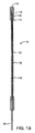
図1A〜図1Dを参照すると、本発明の原理に従って構成された体管腔の穿刺部位の止血を行うシステム10の実施形態の例が示されている。システムは、概略的に、図1Aに示すような位置決め/一時的止血組立体11と、図1Cに示す圧迫組立体50とを有している。位置決め/一時的止血組立体11は、可撓性を有する細長い管状部材12と、位置決め部材13とを有している。位置決め部材13は、図1Aに示すような拡大状態と図1Bに示す縮小状態との間で移動できる拡大可能部材からなる。この拡大可能部材13の全体または一部を覆う膜を設けることもできる。管状部材12の近位端に配置される拡大可能部材13の定置手段は、ハンドル14とプシュ/プル部材15との組合せで構成できる。近位端でのハンドル組立体14は、該ハンドル組立体14と拡大可能部材13とを連結するプシュ/プル部材15を介して、拡大可能部材13を移動させることができる。このプシュ/プル部材15は、拡大可能部材13の定置および縮小を行うことができる充分な支柱強度をもつワイヤの形態に構成できる。上記説明は単に例示を目的とするものであって、必ずしもシステム10の実際の形状、サイズまたは寸法を反映するものではない。このことは、以下の全ての説明についても云えることである。
The same elements are denoted by the same reference numerals in different drawings. The drawings are not necessarily to scale and are illustrative of embodiments of the invention and are not intended to limit the scope of the invention.
Referring to FIGS. 1A-1D, an example embodiment of a
拡大可能部材13の直ぐ近位側の、管状部材12の遠位端は、血管壁の穿刺部位を一時的にシールするのに充分な直径を有している。止血プラグ16は、圧迫バルーンが定置される間の出血を一時的に停止させる。一時的止血プラグ16は、その近位端17がテーパ状になっていて、該プラグ16の使用を容易にしかつ引っ掛かる可能性を回避している。プラグ16は、その最小長さを0.05インチとすることができ、或いは管状部材12の全長に亘る長さにすることができる。プラグ16の直径は、約0.04〜0.2インチの範囲内に定めることができる。一時的止血を達成するためのプラグ16の有効性は、シースサイズおよび穿刺部位の拡大の大きさに基いて定まる。このような場合、位置決め/一時的止血組立体11は、特定サイズまたは一定範囲内のサイズのシースと組み合わせて使用できる。従ってこの場合には、一時的止血プラグ16はシースのサイズに合わせて作られる。例えば、5〜6Frのシースを用いる処置では、一時的止血プラグの直径は約0.070インチにすることができる。この直径は、5Frまでの更に小さいシースで一時的止血を行うのに充分な大きさである。プラグ16はまた、縮小した拡大可能部材13の全体または一部を収容できる大きさにすることができる。一般に、ひとたび閉塞組立体11が適用されたときは、シースを除去することが望まれている。従って、位置決め/一時的止血組立体11は、使用されるシースの内径より小さい断面プロファイルにすることができる。
The distal end of the
ここで図1Cを参照すると、止血システム10の圧迫組立体50は、細長い管状部材51、53と、圧迫バルーン55とを有している。第一管状部材51の内径は、位置決め/一時的止血組立体11の全体または少なくとも一部を受け入れることができる充分な長さを有するのが好ましい。図示のように、圧迫管状部材51の近位端には、シリコーンシール等のシーリング機構52が設けられている。圧迫管状部材51は血液に連通することがあるので、シール52は、システム10から血液が流出するのを防止する。シール52は、圧迫管状部材51の長さに沿う任意の位置に配置できる。シール52から圧迫部材51の遠位端までの、該圧迫部材51の長さは、位置決め/一時的止血組立体11の長さよりかなり短く、約1/2である。位置決め組立体11の長さは、約4〜18インチ、好ましくは約8〜12インチにすることができる。これにより、部材11が血管内に配置されたときに、組立体11のハンドル組立体14を、シール52を通して確実に押出すことが可能になる。
Referring now to FIG. 1C, the
第二可撓性管状部材53は、第一管状部材51と同心状でかつ該第一管状部材51を収容している。この第二管状部材53は、第一管状部材51の全長だけ遠位側に伸長できる。2つの管状部材51、53は、矢印54で示すように近位側に向かって二股に分かれている。これらの2つの管状部材51、53は、共通の押出成形法を用いて多ルーメンチュービングから製造できることは理解されよう。一般に、全ての管状部材12、51、53は、ポリエステル(例えば、ポリエチレンテレフタレート)、PEBAX(R)、PEEK(R)、ナイロン、ポリ塩化ビニル、および同様な医用材料から形成できる。圧迫組立体50の遠位端には圧迫バルーン55が設けられ、該バルーン55はその遠位端56および近位端57が取付けられている。バルーン55は、圧迫組立体50の2つの管状部材51、53の間に形成された膨張ルーメン58に連通している。第二管状部材53の近位端にはルアロック59が設けられており、該ルアロックは、圧迫バルーン55を膨張させる目的でバルーン55内に空気または食塩水等の流体をポンピングするシリンジ60等を取付ける。ひとたびバルーンが膨張されたならばその所望圧力に維持するため、膨張組立体には、ルアロック59の遠位側にストップコック61を設けることができる。器具には、圧迫バルーン55が所望圧力に到達する時点を自動化しかつ視覚的に確認する圧力逃し弁62を設けることができる。圧力逃し弁62は、圧迫バルーン55に加えるべき必要な圧力を当て推量する。
The second
ここで図1Dを参照すると、ここには、位置決め/一時的止血組立体11と圧迫組立体50との相互作用が示されている。位置決め/一時的止血組立体11は、圧迫バルーン55の遠位側チップ56が組立体11の位置決め拡大可能部材13から近位側の一定距離に位置するように圧迫組立体50内で摺動する。位置決めは、位置決め組立体11の整合マーク18が圧迫組立体50のシール52の直ぐ外側に位置するように、両組立体11、50の視覚マークを整合させることにより達成される。或いは、位置決めは、機械的干渉またはラッチング機構の結果として達成できる。ラッチング機構は、両管状組立体11、50がラッチしたときに音を発生するか、触覚フィードバッグを与えるように設計できる。ひとたび両組立体がラッチすると、ラッチング機構は、組立体11が最小の力で遠位側に移動することを可能にする。しかしながら、このデテントは、組立体11に対して圧迫組立体50が更に前方移動することを妨げる。圧迫バルーン55が膨張されるときは、圧迫部材50に対して組立体11が遠位側に移動することが望まれる。圧迫バルーン55が膨張されると、血管壁を遠位側に押しやる。例えば1〜20オンス、好ましくは5〜10オンスの最小力で組立体11を同方向に移動させると、血管壁に加えられる応力がなくなる。
Referring now to FIG. 1D, there is shown the interaction of positioning /
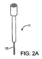
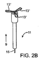
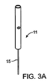
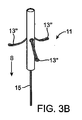
位置決め組立体11の拡大可能部材13は種々の形態をとることができる。或る拡大可能部材は、定置手段15を前方に押すことにより定置される。図2Aおよび図2Bは、このような一例のプッシュ型拡大可能部材13′が、それぞれ、縮小状態および定置状態にあるところを示す。より詳しくは、プシュ/プル部材15を矢印9で示すように遠位側におすと、ファン状の拡大可能部材13′が定置される。他の例は、拡大可能部材13″の遠位端に連結された定置手段15を備えたものであり、定置手段15を引出すことにより拡大可能部材13″が定置される。図3Aおよび図3Bは、一例のプル型拡大可能部材13″が、それぞれ、縮小状態および定置状態にあるところを示す。より詳しくは、プシュ/プル部材15を矢印8で示すように近位側に引っ張ると、フックすなわちプロング13″が定置される。
The
定置された拡大可能部材13はかなり大きい断面直径を形成し、このため、組立体11が血管内で引出されて拡大可能部材が血管壁に対して座合すると、拡大可能部材はこの移動に対して大きい抵抗を発生し、従って血管腔内の穿刺部位に対して組立体11を位置決めする。定置された状態で、拡大可能部材13は、約0.05〜0.5インチ、好ましくは約0.15〜0.30インチの範囲内の直径を形成する。拡大可能部材13は、例えばステンレス鋼、形状記憶材料、超弾性材料(例えばNITINOLTMワイヤ)等の適当な金属で作ることができ、これらの材料は、永久変形することなく伸ばされ、縮小されまたは拘束されるが、自由になったときすなわち拘束されなくなったときは、体温で拡大形状に戻ることができる。
The deployed
圧迫バルーン55は種々の機能を遂行するように設計され、特にプリフォームまたはプリモールドされたバルーンの場合には特定の挙動を呈する。例えば、バルーン55の近位端57は円錐状に作ることができる。図4Aは、簡単な円錐状の圧迫バルーン70の一例を示す。バルーン70の膨張中、頂点71に近い部分が最初にその最大直径に膨張し、次に膨張が遠位側に伝播する。この膨張プロセスは組織内でのバルーン70の安定化を補助しかつ圧迫組立体50の横方向変位を防止する。
The
ここで図5Aを参照すると、ここには、加圧されると折畳みが開かれる複数の同心状折畳み部を備えた他のバルーンが示されている。図5Aは、組立体に取付けられる前の圧迫バルーン80を示す。バルーン80は、複数の折畳み部81を有している。折畳みが開かれるプロセスで、バルーンの遠位端82が前方に移動され、バルーンの前方の組織を穿刺部位に対して圧迫する。バルーン取付け領域84の直ぐ近位側の部分83は、バルーンを伸ばすべくバルーンの折畳みが開かれるときに取付け位置上に折畳まれる。図5Bおよび図5Cは、それぞれ、膨張前および膨張後の、取付けられたバルーン80を示す。
Referring now to FIG. 5A, there is shown another balloon with a plurality of concentric folds that, when pressed, open the fold. FIG. 5A shows the
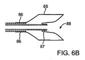
ここで図6Aを参照すると、ここには、更に別の設計による、組立体に取付ける前の圧迫バルーンが示されている。バルーン85は、両取付け位置86、87間で折畳まれかつスタックされる。図6Bは、このバルーン85が膨張されたところを示す。このバルーン85の設計および取付けは、前方組織の圧迫を考慮したものである。このバルーン85は、完全膨張時に凹状遠位端88を形成できる。バルーン85の凹状部分88は、穿刺部位でより大きい凝固を形成することができる。
Referring now to FIG. 6A, there is shown a compression balloon prior to attachment to the assembly according to yet another design.
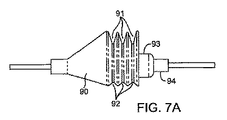
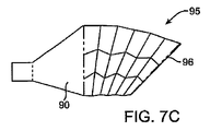
ここで図7Aを参照すると、組立体に取付ける前のバルーンの他の例が示されている。血管壁へのシースの導入が垂直でないことがあるため、バルーンは非対称的に成形されている。完全膨張時のバルーン90では、底側よりも頂側で、より大きい伸びが得られる。これは、大きい伸びを必要とする側のバルーン材料に深い折畳み部91を形成し、反対側に浅い折畳み部92を形成することにより達成される。取付け位置94の直ぐ近位側の部分93は、バルーンが加圧されたときに取付け位置94上に折畳まれることにより、バルーンを伸ばすことができる。このような位置決め/一時的止血組立体11は、圧迫組立体に対して同心状でないどころか、オフセットしている。例えば、組立体11は、圧迫バルーン90の底側壁92に近接して配置される。このオフセットは、非対称的性質の結果としてバルーン90の膨張中に生じたターン95を補償し、従って図7Cに示すように、完全膨張時にバルーンの遠位端96の中心を穿刺部位上に合わせる。図7Bは、膨張前のこのバルーン設計を示す。成形方法がこのような効果を補償できる場合には、バルーンは、血管壁に対してシースが形成する角度と同様に、遠位端面が組立体シャフトに対して或る角度を形成するように設計できることは明らかである。
Referring now to FIG. 7A, another example of a balloon prior to attachment to the assembly is shown. The balloon is asymmetrically shaped because the introduction of the sheath into the vessel wall may not be vertical. With the
図4Bに戻って説明すると、バルーンは、完全膨張時に、バルーンの遠位端面が血管壁に対して凹状面を形成するように設計できまたは取付けることができる。簡単な円錐状バルーン70では、これは、バルーン70を、完全膨張時に非拘束バルーンが配置される位置73より近位側の位置72で、組立体のシャフトに取付けることにより達成できる。これは、バルーン80、90のような折畳み部を備えた場合には、部分83、93の長さを、膨張の結果として生じるバルーンの長さの増大より短くすることにより達成される。
Referring back to FIG. 4B, the balloon can be designed or attached so that when fully inflated, the distal end surface of the balloon forms a concave surface with respect to the vessel wall. For a simple
圧迫バルーン55、70、80、85または90は、一般に、高圧に耐え得る材料で形成される。バルーンは、組織路の周囲の皮下組織を拡大し、該組織を穿刺部位に対して圧迫できる充分な高圧に耐えるように設計すべきである。このような材料の例として、ポリエチレン、ポリエチレンテレフタレート、ポリテトラフルオロエチレン、ナイロン、ポリウレタン、シリコーン、ラテックス、ポリ塩化ビニルおよび種々のデュロメータ硬度をもつ熱可塑性エラストマーがある。これらの材料は、種々の特性を有している。或る材料は膨張されたときに特殊形状を呈し、また或る材料は弾性を有する。他の高圧材料と比べて、エラストマー材料の長所は、これらの材料の伸び特性にある。従って、エラストマー材料は、膨張前は小さいプロファイルにすることができる。しかしながら、エラストマー材料は、高い圧力に加圧することはできない。また圧迫バルーンには、放射線不透過性材料を組込んで、バルーンの配置が画像で示されかつ確認できるように構成できる。止血プロセスを加速するため、高周波エネルギ等の電気エネルギを穿刺部位に供給することも望ましい。このような場合には、圧迫バルーンを導電性材料でコーティングしておき、電気エネルギを導く手段を形成することができる。
The
圧迫部材は、このように圧迫バルーンと呼ぶ限り、全体または一部が膜で覆われた拡大可能部材で形成できることに留意すべきである。この圧迫組立体は、定置されたとき、周囲の組織を半径方向に拡大できるとともに、前方への拡大により組織を圧迫することもできる。この拡大可能部材の定置は空気または流体の注入を同時に行い、拡大可能部材の拡大および組織圧迫プロセスを補助することができる。このような実施形態は、本件出願人が所有しかつ本願に援用する上記特許文献1により詳細に開示されている。 It should be noted that the compression member can be formed of an expandable member that is entirely or partially covered with a membrane, as long as it is referred to as a compression balloon. When placed, the compression assembly can expand the surrounding tissue in a radial direction and can also compress the tissue by expanding forward. This placement of the expandable member can simultaneously inject air or fluid and assist in the expansion of the expandable member and the tissue compression process. Such an embodiment is disclosed in detail in the above-mentioned Patent Document 1 owned by the present applicant and incorporated herein.
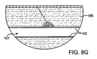
図8A〜図8Gは、対称的圧迫バルーン80について上述した閉塞システム10の作動を示すものである。カテーテル処置の完了時に、シース100は、図8Aに示すように所定位置に留まっている。閉塞システム10の組立体11は、図8Bに示すように、シース100内に摺動可能に受入れられる。組立体11は、拡大可能部材13の遠位端がシース100の外に出て、血管腔101内に入ることを保証するのに充分なだけ、シース100を通して送り込まれる。これは、管状部材12の外面に付したマーキング19により表示できる。所定位置に配置されたならば、プシュ型位置決め機構(図2Aおよび図2B)の場合には、定置ハンドル14を前方に押すことにより拡大可能部材13が定置される。次に、位置決め組立体11は、拡大可能部材13がシース100の遠位側チップに当接するまで引戻される。これは、組立体11が引戻されるときに感じる抵抗として表示される。次に、シース100が身体および組立体11からゆっくりと取出されて廃棄される。図8Cに示すように、組立体11は、位置決め部材13が穿刺部位103で血管壁102に当接して血管内に位置する状態で残され、また一時的止血プラグ16は穿刺部位103の血管壁内に留まった状態に維持されて、血液が漏出することを防止する。
8A-8G illustrate the operation of the
ここで図8Dに示すように、圧迫組立体50の遠位端は組立体11の近位端から挿通され、組立体11の近位端はシール52を突刺すまで圧迫組立体50のルーメンを通され、圧迫組立体50の近位端から出る。次に、圧迫組立体50が、皮膚104の開口および組織路105を通り、圧迫組立体50の遠位端97が血管壁102から所定距離106に位置しかつ皮下組織98に当接するまで、位置決め/一時的止血組立体11の管状部材12上を案内される。この位置決めは、管状部材12上のマーキング18により表示できる。次に図8Eに示すように、圧迫バルーン80が、目標とする微小圧迫を与えるように、最適圧力に膨張される。今や、血管壁102の穿刺部位103上の圧迫組織107が、止血手段を形成できるようになった。次に、図8Fに示すように、閉塞器具の組立体11が縮小されかつ圧迫組立体50のルーメンを通って体外に取出される。圧迫組立体50は、身体の自然の傷治癒メカニズムが止血を達成するのに必要である限り、身体内に留まる。次に、バルーン80が収縮され、図8Gに示すように、圧迫組立体50が除去される。
8D, the distal end of the
図9A〜図9Cは、本発明の原理に従って構成された体管腔の穿刺部位の止血を行うシステム110の他の実施形態を示すものである。止血システム110は、カテーテル組立体120および膨張組立体140からなる。カテーテル組立体120は、シース100より小さい断面プロファイルを有している。図9Aは、圧迫バルーン126と該圧迫バルーン126を膨張させるための第二管状部材127とが一体化された位置決め/一時的止血機構121、124(および定置手段)を備えたカテーテル組立体120を示している。カテーテル組立体120は、位置決め拡大可能部材121と、該部材121の定置および縮小を行う手段すなわち、プシュ/プル部材122およびハンドル組立体123とを有している。プシュ/プル部材122は、シール131を通って第一管状部材125の近位端から出ている。第一管状部材125は血液と連通するので、シール131は血液の流出を防止する。ハンドル組立体123の移動は、第一管状部材125の近位端と、拡大可能121と第一管状部材125の遠位端との干渉とによって制限される。プラグ部材124および管状部材125の移動は、部分132と第二管状部材127の近位端との干渉により、および部分130でのプラグ124と管状部材127の遠位端との干渉により制限される。
9A-9C illustrate another embodiment of a
或る実施形態では、圧迫バルーン126が膨張されたときに、拡大可能部材121および止血プラグ124が遠位側方向に向かって前方に自由に移動できることが望まれることがある。従って、両管状部材125、127の相対位置の中間位置は、部分132が管状部材127の近位端と干渉する前に確立される。この位置において拡大可能部材121および止血プラグ124が定置され、圧迫バルーン126が、血管壁102に対して所望距離に配置される。この中間位置は、視覚マークまたは前述のような機械的デテントにより認識できる。拡大可能部材121の定置および縮小機構122および一時的止血プラグ124は、最初に一時的止血プラグ124が定置され、次に位置決め機構121が定置されるように設計するのが望ましいこともある。これらの部材が縮小されるとき、位置決め部材121が最初に止血プラグ124内に後退され、次にプラグ124が第二管状部材127内に後退される。
In certain embodiments, it may be desired that the
一時的止血プラグ124は、可撓性を有する細長い第一管状部材の遠位端に設けられている。圧迫バルーン126は、可撓性を有する第二管状部材127の遠位端に取付けられている。第二管状部材127は、可撓性のある膨張チューブ128に終端している。第二管状部材127は、ポート129を介して圧迫バルーン126に流体連通している。両管状部材125、127は、図9Aに示すように互いに移動できる。拡大可能部材121および一時的止血プラグ124は、圧迫バルーン126が膨張された後に、部分130において、第二管状部材127内に後退されかつ収容される。システム110はまた、両管状部材125、127が互いに固定されるように設計できる。このような場合には、膨張プロセスおよび圧迫バルーン126の遠位側の拡大によって両部材121、124が血管腔101および血管壁102から後退されかつ取出される。図9Bは膨張組立体140を示し、該膨張組立体140は、概略的に、膨張機構140をカテーテル組立体120の膨張チューブ128に連結するクイックコネクタ141と、圧力逃し弁142と、ストップコック143と、シリンジ145を取付けるルアロック144とを有している。
A
所定位置に配置されたシース100を用いたシステム110の作動は、カテーテル組立体120のチップがシース100の外に出て、血管腔101内に入るまで、シース100を通してカテーテル組立体120を位置決めすることを含んでいる。図9Aに示すように、これは、第二管状部材127に設けられたマーク133により表示される。第一管状部材125を前方に移動して、プラグ124を露出させる。次にハンドル組立体123を前方に移動して、拡大可能部材121を定置する。次に、拡大可能部材121がシース100の遠位端に位置していることを示す抵抗が感じられるまで、カテーテル組立体120が引戻される。拡大可能部材121を血管壁102の内面に当接させた状態にしておきかつ止血プラグ124を血管壁102の穿刺部位103に留めておき、シースをカテーテル120の全長に亘って引戻しかつ身体からゆっくりと取出す。シース100は廃棄できる。今や、圧迫バルーン126は、血管壁102から所定距離106の位置に配置されかつ固定されたことになる。
Actuation of the
次に、図9Cに示すように、膨張組立体140を、クイックコネクタ141を介して膨張チューブ128に連結される。空気、食塩水、その他の薬剤(例えば、凝固促進溶液)またはこれらの組合せを収容するシリンジ145が、ルアロック144に連結される。ストップコック143を膨張/収縮位置にしてバルーン126を所望の膨張圧力に膨張させると、バルーン126が半径方向および軸線方向に拡大されかつ皮下組織107が穿刺部位103に対して圧迫されて、血圧に打勝ちかつ止血が行われる。空気または流体が圧力逃し弁142から出ると、膨張プロセスは完了する。ストップコック143を回転させて、圧迫バルーン126内に圧力を維持できる位置に保持する。次にハンドル組立体123を操作して、最初に位置決め部材121を、次に一時的止血プラグ124を連続的に後退させる。圧迫バルーン126は、皮下組織98に対して一定時間膨張された状態に維持できる。所望圧迫時間が経過したならば、ストップコック143が膨張/収縮位置に切換えられる。シリンジ145は、圧迫バルーン126から媒体を除去して、バルーン126を管状部材127の周囲に更に収縮させるのに使用できる。次に、カテーテル組立体120が身体から取出される。
Next, as shown in FIG. 9C, the
図10には、本発明の原理に従って構成された体管腔の穿刺部位の止血を行うシステム110′の更に別の実施形態が示されている。これは、図9A〜図9Cに関連して上述した全ての作動要素を含む一体化された単体構造120である。この実施形態では、システム110′の膨張組立体140′は、シース100よりかなり大きいプロファイルを有している。いずれにせよ、可撓性を有する細長い第二管状部材127は、位置決め拡大可能部材121および一時的止血プラグ124が定置されるときに、身体からシース100を完全に取出すことができる充分な長さで作られている。シース100は、止血が達成されかつシステム110′が取出されるまで、組立体120と一緒に留まっている。
FIG. 10 illustrates yet another embodiment of a
図11A〜図11Cは、本発明の原理に従って構成された体管腔の穿刺部位の止血を行うシステム200の更に別の実施形態を示すものである。これも、図9A〜図9Cに関連して上述した幾つかの作動要素を有する一体構造を有している。例えば、位置決め拡大可能部材151、プシュ/プル部材152、一時的止血プラグ153、圧迫バルーン154、155およびハンドル組立体156の機能は、前述のものと同じである。図11Cに示すように、ポンピング機構は、圧縮シール157およびポンプハンドル158を有している。ポンプ組立体157、158は、圧迫バルーン154を膨張させるべく、ピストン159内で空気を圧縮する。図11Bに示すように、バルーン154は、開口160を介してピストン159に流体連通している。システム200は、使用されるシース100の内径より小さい断面プロファイルを有している。従って、シース100は、位置決め拡大可能部材151および一時的止血プラグ153が血管内に適当に定置されかつ配置されるときに、システム200全体を摺動することができる。
11A-11C illustrate yet another embodiment of a
以上、理解の明瞭化を図るため、或る例示実施形態および方法を幾分詳細に説明したが、当業者ならば、本発明の精神および範囲から逸脱することなく、これらの実施形態および方法の種々の変更をなし得ることは明白である。従って、上記説明は、特許請求の範囲により定められた本発明の範囲を限定するものであると解釈すべきではない。 Although certain illustrative embodiments and methods have been described in some detail for purposes of clarity of understanding, those skilled in the art will understand how to implement these embodiments and methods without departing from the spirit and scope of the invention. Obviously, various changes can be made. Therefore, the above description should not be taken as limiting the scope of the invention which is defined by the appended claims.
10 止血システム
11 位置決め/一時的止血組立体(閉塞組立体)
13 位置決め部材(拡大可能部材)
14 ハンドル組立体
15 プシュ/プル部材
16 一時的止血プラグ
18、19 整合マーク
50 圧迫組立体
55 膨張バルーン
60 シリンジ
10
13 Positioning member (expandable member)
14
Claims (67)
近位端と、遠位端と、該遠位端に配置された拡大可能要素とを備えた圧迫部材を設ける段階と、
皮膚表面の開口を通して圧迫部材を挿入する段階と、
拡大可能要素の遠位端を、血管壁から所定距離隔てた位置に位置決めする段階と、
拡大可能要素を、組織路内で皮下組織に対して拡大する段階とを有することを特徴とする方法。 In the method of hemostasis the puncture site of the blood vessel at one end of the tissue tract,
Providing a compression member comprising a proximal end, a distal end, and an expandable element disposed at the distal end;
Inserting a compression member through an opening in the skin surface;
Positioning the distal end of the expandable element at a distance from the vessel wall;
Expanding the expandable element relative to the subcutaneous tissue within the tissue tract.
請求項1に記載の血管の穿刺部位の止血を行う圧迫部材を使用する指示とからなることを特徴とするキット。 A compression member;
A kit comprising: an instruction to use a compression member for hemostasis of the puncture site of the blood vessel according to claim 1.
該位置決め部材と少なくとも一部が同心状である圧迫部材とを有し、該圧迫部材は近位端と、遠位端と、該遠位端に配置された拡大可能要素とを備え、拡大可能部材は、体管腔の壁から所定距離離れた位置に位置決めできることを特徴とする体管腔の穿刺部位の止血を行うシステム。 A positioning member comprising a proximal end, a distal end, and an expandable member disposed at the distal end;
The positioning member and a compression member that is at least partially concentric, the compression member comprising a proximal end, a distal end, and an expandable element disposed at the distal end and is expandable A system for performing hemostasis of a puncture site of a body lumen, wherein the member can be positioned at a position away from the wall of the body lumen by a predetermined distance.
近位端および遠位端を備え第二管状部材とを有し、該第二管状部材は第一管状部材との間に膨張ルーメンを形成すべく、少なくとも一部が第一管状部材と同心状であり、
第一管状部材および第二管状部材の遠位端に配置されかつ膨張ルーメンに連通するバルーンを更に有し、該バルーンの遠位端は、位置決め手段の後方でかつ体管腔の壁から所定距離を隔てた位置に位置決め可能であることを特徴とする体管腔の穿刺部位の止血を行う器具。 A first tubular member having a proximal end and a distal end;
A second tubular member having a proximal end and a distal end, the second tubular member being at least partially concentric with the first tubular member to form an inflation lumen with the first tubular member And
The balloon further includes a balloon disposed at the distal ends of the first tubular member and the second tubular member and in communication with the inflation lumen, the distal end of the balloon being behind the positioning means and a predetermined distance from the wall of the body lumen A device for hemostasis of a puncture site of a body lumen, characterized in that the device can be positioned at a position separated from each other.
Applications Claiming Priority (2)
| Application Number | Priority Date | Filing Date | Title |
|---|---|---|---|
| US10/821,633 US9017374B2 (en) | 2004-04-09 | 2004-04-09 | Device and method for sealing blood vessels |
| PCT/US2005/011648 WO2005099590A2 (en) | 2004-04-09 | 2005-04-06 | Device and method for sealing blood vessels |
Publications (2)
| Publication Number | Publication Date |
|---|---|
| JP2008501372A true JP2008501372A (en) | 2008-01-24 |
| JP2008501372A5 JP2008501372A5 (en) | 2008-05-29 |
Family
ID=35061585
Family Applications (1)
| Application Number | Title | Priority Date | Filing Date |
|---|---|---|---|
| JP2007507469A Pending JP2008501372A (en) | 2004-04-09 | 2005-04-06 | Vascular sealing instrument and method |
Country Status (4)
| Country | Link |
|---|---|
| US (2) | US9017374B2 (en) |
| EP (1) | EP1732450A2 (en) |
| JP (1) | JP2008501372A (en) |
| WO (1) | WO2005099590A2 (en) |
Cited By (1)
| Publication number | Priority date | Publication date | Assignee | Title |
|---|---|---|---|---|
| JP2016533863A (en) * | 2013-10-16 | 2016-11-04 | メッドワークス, エルエルシーMedwerks, Llc | Non-invasive medical device |
Families Citing this family (88)
| Publication number | Priority date | Publication date | Assignee | Title |
|---|---|---|---|---|
| US9579091B2 (en) | 2000-01-05 | 2017-02-28 | Integrated Vascular Systems, Inc. | Closure system and methods of use |
| US8758400B2 (en) | 2000-01-05 | 2014-06-24 | Integrated Vascular Systems, Inc. | Closure system and methods of use |
| US6391048B1 (en) | 2000-01-05 | 2002-05-21 | Integrated Vascular Systems, Inc. | Integrated vascular device with puncture site closure component and sealant and methods of use |
| US6461364B1 (en) | 2000-01-05 | 2002-10-08 | Integrated Vascular Systems, Inc. | Vascular sheath with bioabsorbable puncture site closure apparatus and methods of use |
| US7842068B2 (en) | 2000-12-07 | 2010-11-30 | Integrated Vascular Systems, Inc. | Apparatus and methods for providing tactile feedback while delivering a closure device |
| AU8800801A (en) | 2000-09-08 | 2002-03-22 | James E Coleman | Surgical staple |
| US6626918B1 (en) | 2000-10-06 | 2003-09-30 | Medical Technology Group | Apparatus and methods for positioning a vascular sheath |
| US8690910B2 (en) | 2000-12-07 | 2014-04-08 | Integrated Vascular Systems, Inc. | Closure device and methods for making and using them |
| US6623510B2 (en) | 2000-12-07 | 2003-09-23 | Integrated Vascular Systems, Inc. | Closure device and methods for making and using them |
| US7211101B2 (en) | 2000-12-07 | 2007-05-01 | Abbott Vascular Devices | Methods for manufacturing a clip and clip |
| US7905900B2 (en) | 2003-01-30 | 2011-03-15 | Integrated Vascular Systems, Inc. | Clip applier and methods of use |
| US6695867B2 (en) | 2002-02-21 | 2004-02-24 | Integrated Vascular Systems, Inc. | Plunger apparatus and methods for delivering a closure device |
| IES20010547A2 (en) | 2001-06-07 | 2002-12-11 | Christy Cummins | Surgical Staple |
| US7850709B2 (en) | 2002-06-04 | 2010-12-14 | Abbott Vascular Inc. | Blood vessel closure clip and delivery device |
| US8202293B2 (en) | 2003-01-30 | 2012-06-19 | Integrated Vascular Systems, Inc. | Clip applier and methods of use |
| US8398656B2 (en) | 2003-01-30 | 2013-03-19 | Integrated Vascular Systems, Inc. | Clip applier and methods of use |
| US8821534B2 (en) * | 2010-12-06 | 2014-09-02 | Integrated Vascular Systems, Inc. | Clip applier having improved hemostasis and methods of use |
| US8758398B2 (en) | 2006-09-08 | 2014-06-24 | Integrated Vascular Systems, Inc. | Apparatus and method for delivering a closure element |
| US8905937B2 (en) | 2009-02-26 | 2014-12-09 | Integrated Vascular Systems, Inc. | Methods and apparatus for locating a surface of a body lumen |
| US7223266B2 (en) | 2003-02-04 | 2007-05-29 | Cardiodex Ltd. | Methods and apparatus for hemostasis following arterial catheterization |
| US20080154303A1 (en) | 2006-12-21 | 2008-06-26 | Cardiva Medical, Inc. | Hemostasis-enhancing device and method for its use |
| US7572274B2 (en) * | 2004-05-27 | 2009-08-11 | Cardiva Medical, Inc. | Self-tensioning vascular occlusion device and method for its use |
| US20050267520A1 (en) | 2004-05-12 | 2005-12-01 | Modesitt D B | Access and closure device and method |
| IES20040368A2 (en) | 2004-05-25 | 2005-11-30 | James E Coleman | Surgical stapler |
| US7678133B2 (en) | 2004-07-10 | 2010-03-16 | Arstasis, Inc. | Biological tissue closure device and method |
| JP5068662B2 (en) | 2004-11-22 | 2012-11-07 | カーディオデックス リミテッド | Heat treatment technology for varicose veins |
| JP2008531498A (en) | 2005-02-15 | 2008-08-14 | バージニア コモンウェルス ユニバーシティ | Mineral technology (MT) for emergency hemostasis and treatment of acute wounds and chronic ulcers |
| CN101217916B (en) | 2005-05-12 | 2013-04-10 | 阿尔斯塔西斯公司 | Access and closure device and method |
| US8926633B2 (en) | 2005-06-24 | 2015-01-06 | Abbott Laboratories | Apparatus and method for delivering a closure element |
| US8313497B2 (en) | 2005-07-01 | 2012-11-20 | Abbott Laboratories | Clip applier and methods of use |
| US7691127B2 (en) | 2005-12-13 | 2010-04-06 | Cardiva Medical, Inc. | Drug eluting vascular closure devices and methods |
| US9179897B2 (en) | 2005-12-13 | 2015-11-10 | Cardiva Medical, Inc. | Vascular closure devices and methods providing hemostatic enhancement |
| US8911472B2 (en) | 2005-12-13 | 2014-12-16 | Cardiva Medical, Inc. | Apparatus and methods for delivering hemostatic materials for blood vessel closure |
| US8382794B2 (en) * | 2006-01-04 | 2013-02-26 | St. Jude Medical Puerto Rico Llc | Balloon insertion apparatus and method of sealing a tissue puncture |
| US8808310B2 (en) | 2006-04-20 | 2014-08-19 | Integrated Vascular Systems, Inc. | Resettable clip applier and reset tools |
| US7604819B2 (en) | 2006-05-26 | 2009-10-20 | Z-Medica Corporation | Clay-based hemostatic agents and devices for the delivery thereof |
| US8556930B2 (en) | 2006-06-28 | 2013-10-15 | Abbott Laboratories | Vessel closure device |
| US9427217B2 (en) * | 2007-02-05 | 2016-08-30 | Boston Scientific Scimed Inc. | Apparatus and method for closing an opening in a blood vessel using memory metal and collagen |
| US8133242B1 (en) | 2007-04-27 | 2012-03-13 | Q-Tech Medical Incorporated | Image-guided extraluminal occlusion |
| US7798385B2 (en) | 2007-05-16 | 2010-09-21 | The Invention Science Fund I, Llc | Surgical stapling instrument with chemical sealant |
| US8485411B2 (en) | 2007-05-16 | 2013-07-16 | The Invention Science Fund I, Llc | Gentle touch surgical stapler |
| US7810691B2 (en) | 2007-05-16 | 2010-10-12 | The Invention Science Fund I, Llc | Gentle touch surgical stapler |
| US7823761B2 (en) | 2007-05-16 | 2010-11-02 | The Invention Science Fund I, Llc | Maneuverable surgical stapler |
| US7832611B2 (en) | 2007-05-16 | 2010-11-16 | The Invention Science Fund I, Llc | Steerable surgical stapler |
| US7922064B2 (en) | 2007-05-16 | 2011-04-12 | The Invention Science Fund, I, LLC | Surgical fastening device with cutter |
| US8366706B2 (en) | 2007-08-15 | 2013-02-05 | Cardiodex, Ltd. | Systems and methods for puncture closure |
| US8568445B2 (en) | 2007-08-21 | 2013-10-29 | St. Jude Medical Puerto Rico Llc | Extra-vascular sealing device and method |
| US8333787B2 (en) | 2007-12-31 | 2012-12-18 | St. Jude Medical Puerto Rico Llc | Vascular closure device having a flowable sealing material |
| US8893947B2 (en) | 2007-12-17 | 2014-11-25 | Abbott Laboratories | Clip applier and methods of use |
| US20090157101A1 (en) | 2007-12-17 | 2009-06-18 | Abbott Laboratories | Tissue closure system and methods of use |
| US7841502B2 (en) | 2007-12-18 | 2010-11-30 | Abbott Laboratories | Modular clip applier |
| US9282953B2 (en) | 2007-12-31 | 2016-03-15 | St. Jude Medical Puerto Rico Llc | Systems and methods for locating and closing a tissue puncture |
| US8840640B2 (en) | 2007-12-31 | 2014-09-23 | St. Jude Medical Puerto Rico Llc | Vascular closure device having an improved plug |
| US20090227938A1 (en) * | 2008-03-05 | 2009-09-10 | Insitu Therapeutics, Inc. | Wound Closure Devices, Methods of Use, and Kits |
| US8361100B2 (en) * | 2008-03-17 | 2013-01-29 | Ethicon, Inc. | Applicator instruments for the delivery, deployment, and tamponade of hemostats and methods therefor |
| US9282965B2 (en) | 2008-05-16 | 2016-03-15 | Abbott Laboratories | Apparatus and methods for engaging tissue |
| JP2011528605A (en) | 2008-07-21 | 2011-11-24 | アルスタシス,インコーポレイテッド | Device, method, and kit for forming a tube in tissue |
| US8398676B2 (en) | 2008-10-30 | 2013-03-19 | Abbott Vascular Inc. | Closure device |
| US8858594B2 (en) | 2008-12-22 | 2014-10-14 | Abbott Laboratories | Curved closure device |
| US9089311B2 (en) | 2009-01-09 | 2015-07-28 | Abbott Vascular Inc. | Vessel closure devices and methods |
| US9486191B2 (en) | 2009-01-09 | 2016-11-08 | Abbott Vascular, Inc. | Closure devices |
| US9414820B2 (en) | 2009-01-09 | 2016-08-16 | Abbott Vascular Inc. | Closure devices, systems, and methods |
| US20100179589A1 (en) | 2009-01-09 | 2010-07-15 | Abbott Vascular Inc. | Rapidly eroding anchor |
| US9173644B2 (en) | 2009-01-09 | 2015-11-03 | Abbott Vascular Inc. | Closure devices, systems, and methods |
| US20100185234A1 (en) | 2009-01-16 | 2010-07-22 | Abbott Vascular Inc. | Closure devices, systems, and methods |
| US20110054492A1 (en) | 2009-08-26 | 2011-03-03 | Abbott Laboratories | Medical device for repairing a fistula |
| US8845682B2 (en) | 2009-10-13 | 2014-09-30 | E-Pacing, Inc. | Vasculature closure devices and methods |
| US8211121B1 (en) | 2010-03-06 | 2012-07-03 | Q-Tech Medical Incorporated | Methods and apparatus for image-guided extraluminal occlusion using clamping jaws |
| US8758399B2 (en) | 2010-08-02 | 2014-06-24 | Abbott Cardiovascular Systems, Inc. | Expandable bioabsorbable plug apparatus and method |
| US8603116B2 (en) | 2010-08-04 | 2013-12-10 | Abbott Cardiovascular Systems, Inc. | Closure device with long tines |
| US8858969B2 (en) | 2010-09-22 | 2014-10-14 | Z-Medica, Llc | Hemostatic compositions, devices, and methods |
| US8617184B2 (en) | 2011-02-15 | 2013-12-31 | Abbott Cardiovascular Systems, Inc. | Vessel closure system |
| US9149276B2 (en) | 2011-03-21 | 2015-10-06 | Abbott Cardiovascular Systems, Inc. | Clip and deployment apparatus for tissue closure |
| WO2012148745A1 (en) * | 2011-04-25 | 2012-11-01 | St. Jude Medical Puerto Rico Llc | Distal balloon bond for temporary sealing location device and methods |
| US8556932B2 (en) | 2011-05-19 | 2013-10-15 | Abbott Cardiovascular Systems, Inc. | Collapsible plug for tissue closure |
| US9332976B2 (en) | 2011-11-30 | 2016-05-10 | Abbott Cardiovascular Systems, Inc. | Tissue closure device |
| US20130317481A1 (en) | 2012-05-25 | 2013-11-28 | Arstasis, Inc. | Vascular access configuration |
| US20130317438A1 (en) | 2012-05-25 | 2013-11-28 | Arstasis, Inc. | Vascular access configuration |
| KR101945031B1 (en) | 2012-06-22 | 2019-02-01 | 지-메디카 엘엘씨 | Hemostatic devices |
| US9364209B2 (en) | 2012-12-21 | 2016-06-14 | Abbott Cardiovascular Systems, Inc. | Articulating suturing device |
| US9067043B2 (en) * | 2013-05-28 | 2015-06-30 | Smh Device Corp. | Tunneled catheter with hemostasis mechanism |
| US9308351B2 (en) | 2013-05-28 | 2016-04-12 | Smh Device Corp. | Tunneled catheter with hemostasis mechanism |
| EP3021762B1 (en) | 2013-07-15 | 2020-03-04 | E-Pacing, Inc. | Vasculature closure devices |
| ES2684405T3 (en) * | 2014-04-08 | 2018-10-02 | Stryker Corporation | Implant delivery system |
| CN106037864B (en) * | 2016-07-21 | 2019-08-06 | 李勇 | A kind of injection aquagel plugging device for ureteroscope lithotrity |
| US20200129164A1 (en) * | 2018-10-24 | 2020-04-30 | M-V Arterica AB | Self-expanding hemostatic devices and methods for fascia and vessel passages |
| JP2023503038A (en) | 2019-11-19 | 2023-01-26 | アーテリカ, インコーポレイテッド | Vascular closure device and method |
| KR102534486B1 (en) * | 2021-02-18 | 2023-05-18 | 인제대학교 산학협력단 | Foley catheter for prevent the urethral injury |
Citations (4)
| Publication number | Priority date | Publication date | Assignee | Title |
|---|---|---|---|---|
| JP2000507838A (en) * | 1995-09-15 | 2000-06-27 | サブキュー インコーポレイテッド | Apparatus and method for percutaneously sealing a vascular puncture |
| JP2001509415A (en) * | 1997-07-08 | 2001-07-24 | ザ リージェンツ オブ ザ ユニヴァーシティー オブ カリフォルニア | Peripheral resection device assembly and method |
| JP2002513308A (en) * | 1997-02-11 | 2002-05-08 | バイオインターベンショナル コーポレイション | Dilation device for use in blood vessels and ducts of the human body, tensioning device and method for use in the device |
| WO2004012605A1 (en) * | 2002-08-01 | 2004-02-12 | Abbott Laboratories Vascular Enterprises, Limited | Apparatus for sealing a puncture by causing a reduction in the circumference of the puncture |
Family Cites Families (57)
| Publication number | Priority date | Publication date | Assignee | Title |
|---|---|---|---|---|
| US4714074A (en) * | 1985-06-28 | 1987-12-22 | Centre National De La Recherche Scientifique | Method for protecting human or animal organs against radiation |
| US4744364A (en) * | 1987-02-17 | 1988-05-17 | Intravascular Surgical Instruments, Inc. | Device for sealing percutaneous puncture in a vessel |
| US4852568A (en) * | 1987-02-17 | 1989-08-01 | Kensey Nash Corporation | Method and apparatus for sealing an opening in tissue of a living being |
| US4890612A (en) * | 1987-02-17 | 1990-01-02 | Kensey Nash Corporation | Device for sealing percutaneous puncture in a vessel |
| US5290552A (en) * | 1988-05-02 | 1994-03-01 | Matrix Pharmaceutical, Inc./Project Hear | Surgical adhesive material |
| US5061274A (en) * | 1989-12-04 | 1991-10-29 | Kensey Nash Corporation | Plug device for sealing openings and method of use |
| US5197971A (en) * | 1990-03-02 | 1993-03-30 | Bonutti Peter M | Arthroscopic retractor and method of using the same |
| DE69102515T2 (en) * | 1990-04-02 | 1994-10-20 | Kanji Inoue | DEVICE FOR CLOSING A SHUTTER OPENING BY MEANS OF A NON-OPERATIONAL METHOD. |
| US5108421A (en) * | 1990-10-01 | 1992-04-28 | Quinton Instrument Company | Insertion assembly and method of inserting a vessel plug into the body of a patient |
| US5419765A (en) * | 1990-12-27 | 1995-05-30 | Novoste Corporation | Wound treating device and method for treating wounds |
| NL9101051A (en) | 1991-06-18 | 1993-01-18 | Ashridge Ag | CLOSING DEVICE FOR A VESSEL OR THE LIKE. |
| CA2074304C (en) * | 1991-08-02 | 1996-11-26 | Cyril J. Schweich, Jr. | Drug delivery catheter |
| US5258000A (en) | 1991-11-25 | 1993-11-02 | Cook Incorporated | Tissue aperture repair device |
| US5383898A (en) * | 1991-12-13 | 1995-01-24 | Sarfarazi; Faezeh M. | Sarfarazi corneal incision closure |
| CA2134071C (en) * | 1992-04-23 | 1999-04-27 | Sew Wah Tay | Apparatus and method for sealing vascular punctures |
| US5810810A (en) * | 1992-04-23 | 1998-09-22 | Scimed Life Systems, Inc. | Apparatus and method for sealing vascular punctures |
| US5413571A (en) * | 1992-07-16 | 1995-05-09 | Sherwood Medical Company | Device for sealing hemostatic incisions |
| US5292332A (en) * | 1992-07-27 | 1994-03-08 | Lee Benjamin I | Methods and device for percutanceous sealing of arterial puncture sites |
| WO1994010949A1 (en) * | 1992-11-10 | 1994-05-26 | Joseph Devenuto | Method and apparatus for inserting an intraocular lens |
| US5456667A (en) | 1993-05-20 | 1995-10-10 | Advanced Cardiovascular Systems, Inc. | Temporary stenting catheter with one-piece expandable segment |
| US5383896A (en) | 1993-05-25 | 1995-01-24 | Gershony; Gary | Vascular sealing device |
| US5951583A (en) * | 1993-05-25 | 1999-09-14 | Vascular Solutions, Inc. | Thrombin and collagen procoagulant and process for making the same |
| US5868778A (en) * | 1995-10-27 | 1999-02-09 | Vascular Solutions, Inc. | Vascular sealing apparatus and method |
| US5626601A (en) * | 1995-10-27 | 1997-05-06 | Gary Gershony | Vascular sealing apparatus and method |
| US6017359A (en) * | 1993-05-25 | 2000-01-25 | Vascular Solutions, Inc. | Vascular sealing apparatus |
| US5860974A (en) * | 1993-07-01 | 1999-01-19 | Boston Scientific Corporation | Heart ablation catheter with expandable electrode and method of coupling energy to an electrode on a catheter shaft |
| FR2707862B1 (en) | 1993-07-21 | 1995-10-13 | Nycomed Lab Sa | System for temporarily closing an orifice in a perforated organ, such as in particular a vessel. |
| US5486195A (en) * | 1993-07-26 | 1996-01-23 | Myers; Gene | Method and apparatus for arteriotomy closure |
| WO1995005121A1 (en) | 1993-08-12 | 1995-02-23 | Vascular Technologies, Inc. | Catheter introducer with suture capability |
| US5879366A (en) * | 1996-12-20 | 1999-03-09 | W.L. Gore & Associates, Inc. | Self-expanding defect closure device and method of making and using |
| US5634936A (en) * | 1995-02-06 | 1997-06-03 | Scimed Life Systems, Inc. | Device for closing a septal defect |
| US5649959A (en) | 1995-02-10 | 1997-07-22 | Sherwood Medical Company | Assembly for sealing a puncture in a vessel |
| US6071300A (en) * | 1995-09-15 | 2000-06-06 | Sub-Q Inc. | Apparatus and method for percutaneous sealing of blood vessel punctures |
| US5895398A (en) * | 1996-02-02 | 1999-04-20 | The Regents Of The University Of California | Method of using a clot capture coil |
| US5728134A (en) * | 1996-09-17 | 1998-03-17 | Barak; Shlomo | Method and apparatus for hemostasis |
| US5861003A (en) | 1996-10-23 | 1999-01-19 | The Cleveland Clinic Foundation | Apparatus and method for occluding a defect or aperture within body surface |
| US6464712B1 (en) * | 1997-02-11 | 2002-10-15 | Biointerventional Corporation | Expansile device for use in blood vessels and tracts in the body and method |
| US6056769A (en) | 1997-02-11 | 2000-05-02 | Biointerventional Corporation | Expansile device for use in blood vessels and tracts in the body and tension application device for use therewith and method |
| US6056770A (en) * | 1997-02-11 | 2000-05-02 | Biointerventional Corporation | Expansile device for use in blood vessels and tracts in the body and method |
| US5951589A (en) | 1997-02-11 | 1999-09-14 | Biointerventional Corporation | Expansile device for use in blood vessels and tracts in the body and tension application device for use therewith and method |
| WO1998040017A2 (en) | 1997-03-12 | 1998-09-17 | Advanced Closure Systems, Inc. | Vascular sealing device |
| US5851210A (en) | 1997-03-21 | 1998-12-22 | Torossian; Richard | Stent delivery system and method |
| US6012457A (en) | 1997-07-08 | 2000-01-11 | The Regents Of The University Of California | Device and method for forming a circumferential conduction block in a pulmonary vein |
| US5881003A (en) * | 1997-07-16 | 1999-03-09 | International Business Machines Corporation | Method of making a memory device fault tolerant using a variable domain redundancy replacement configuration |
| US6048358A (en) * | 1998-07-13 | 2000-04-11 | Barak; Shlomo | Method and apparatus for hemostasis following arterial catheterization |
| US6296657B1 (en) * | 1998-10-07 | 2001-10-02 | Gregory G. Brucker | Vascular sealing device and method |
| US6248124B1 (en) * | 1999-02-22 | 2001-06-19 | Tyco Healthcare Group | Arterial hole closure apparatus |
| US6146396A (en) * | 1999-03-05 | 2000-11-14 | Board Of Regents, The University Of Texas System | Declotting method and apparatus |
| AU2001273401A1 (en) * | 2000-07-14 | 2002-01-30 | Sub-Q Inc. | Sheath-mounted arterial plug delivery device |
| US6890342B2 (en) * | 2000-08-02 | 2005-05-10 | Loma Linda University | Method and apparatus for closing vascular puncture using hemostatic material |
| US6658207B1 (en) * | 2000-08-31 | 2003-12-02 | Recon/Optical, Inc. | Method of framing reconnaissance with motion roll compensation |
| US6743195B2 (en) * | 2001-03-14 | 2004-06-01 | Cardiodex | Balloon method and apparatus for vascular closure following arterial catheterization |
| US7025776B1 (en) | 2001-04-24 | 2006-04-11 | Advanced Catheter Engineering, Inc. | Arteriotomy closure devices and techniques |
| US20030191493A1 (en) * | 2002-04-05 | 2003-10-09 | Epstein Gordon H. | Device for clot retrieval and distal protection |
| US7223266B2 (en) * | 2003-02-04 | 2007-05-29 | Cardiodex Ltd. | Methods and apparatus for hemostasis following arterial catheterization |
| US7115127B2 (en) * | 2003-02-04 | 2006-10-03 | Cardiodex, Ltd. | Methods and apparatus for hemostasis following arterial catheterization |
| US6913614B2 (en) * | 2003-05-08 | 2005-07-05 | Cardia, Inc. | Delivery system with safety tether |
-
2004
- 2004-04-09 US US10/821,633 patent/US9017374B2/en active Active
-
2005
- 2005-04-06 JP JP2007507469A patent/JP2008501372A/en active Pending
- 2005-04-06 WO PCT/US2005/011648 patent/WO2005099590A2/en not_active Application Discontinuation
- 2005-04-06 EP EP05735344A patent/EP1732450A2/en not_active Withdrawn
-
2015
- 2015-04-13 US US14/685,164 patent/US20150209019A1/en not_active Abandoned
Patent Citations (4)
| Publication number | Priority date | Publication date | Assignee | Title |
|---|---|---|---|---|
| JP2000507838A (en) * | 1995-09-15 | 2000-06-27 | サブキュー インコーポレイテッド | Apparatus and method for percutaneously sealing a vascular puncture |
| JP2002513308A (en) * | 1997-02-11 | 2002-05-08 | バイオインターベンショナル コーポレイション | Dilation device for use in blood vessels and ducts of the human body, tensioning device and method for use in the device |
| JP2001509415A (en) * | 1997-07-08 | 2001-07-24 | ザ リージェンツ オブ ザ ユニヴァーシティー オブ カリフォルニア | Peripheral resection device assembly and method |
| WO2004012605A1 (en) * | 2002-08-01 | 2004-02-12 | Abbott Laboratories Vascular Enterprises, Limited | Apparatus for sealing a puncture by causing a reduction in the circumference of the puncture |
Cited By (1)
| Publication number | Priority date | Publication date | Assignee | Title |
|---|---|---|---|---|
| JP2016533863A (en) * | 2013-10-16 | 2016-11-04 | メッドワークス, エルエルシーMedwerks, Llc | Non-invasive medical device |
Also Published As
| Publication number | Publication date |
|---|---|
| WO2005099590A2 (en) | 2005-10-27 |
| US20050228443A1 (en) | 2005-10-13 |
| EP1732450A2 (en) | 2006-12-20 |
| US9017374B2 (en) | 2015-04-28 |
| US20150209019A1 (en) | 2015-07-30 |
| WO2005099590A3 (en) | 2008-01-17 |
Similar Documents
| Publication | Publication Date | Title |
|---|---|---|
| JP2008501372A (en) | Vascular sealing instrument and method | |
| US10624656B2 (en) | Apparatus and methods for treating obstructions within body lumens | |
| US10130347B2 (en) | Hemostasis-enhancing device and method for its use | |
| JP4508866B2 (en) | Vascular closure clip and delivery device | |
| US7789893B2 (en) | Method and apparatus for promoting hemostasis of a blood vessel puncture | |
| JP5602023B2 (en) | System and method for detecting and sealing tissue perforations | |
| US5411509A (en) | Embolectomy catheter | |
| EP0818178A2 (en) | Anchoring device for sealing percutaneous punctures in vessels | |
| WO2011041578A2 (en) | Detachable balloon catheter | |
| EP1231976A1 (en) | Methods and apparatus for treating body tissues and bodily fluid vessels | |
| EP2082693A1 (en) | Blood flow blocking catheter | |
| US11395907B2 (en) | Expandable tissue dilator for dilating tissue around a spinal column | |
| WO2014083559A1 (en) | Vascular occluding device and methods of use | |
| US9089312B2 (en) | Tamponade for biopsy surgery and method of operation | |
| CN116568232A (en) | Guidewire assembly and method for vessel occlusion during vascular procedures | |
| CN117297678A (en) | Tissue plugging device and method for vascular puncture | |
| JP2005287809A (en) | Medical tool |
Legal Events
| Date | Code | Title | Description |
|---|---|---|---|
| A521 | Request for written amendment filed |
Free format text: JAPANESE INTERMEDIATE CODE: A523 Effective date: 20080403 |
|
| A621 | Written request for application examination |
Free format text: JAPANESE INTERMEDIATE CODE: A621 Effective date: 20080403 |
|
| A131 | Notification of reasons for refusal |
Free format text: JAPANESE INTERMEDIATE CODE: A131 Effective date: 20101213 |
|
| A977 | Report on retrieval |
Free format text: JAPANESE INTERMEDIATE CODE: A971007 Effective date: 20101216 |
|
| A02 | Decision of refusal |
Free format text: JAPANESE INTERMEDIATE CODE: A02 Effective date: 20110627 |