JP2008287191A - Optical fiber, end face sealing method of optical fiber, connecting structure of optical fiber, and optical connector - Google Patents
Optical fiber, end face sealing method of optical fiber, connecting structure of optical fiber, and optical connector Download PDFInfo
- Publication number
- JP2008287191A JP2008287191A JP2007134772A JP2007134772A JP2008287191A JP 2008287191 A JP2008287191 A JP 2008287191A JP 2007134772 A JP2007134772 A JP 2007134772A JP 2007134772 A JP2007134772 A JP 2007134772A JP 2008287191 A JP2008287191 A JP 2008287191A
- Authority
- JP
- Japan
- Prior art keywords
- optical fiber
- curable resin
- curing
- fiber
- face
- Prior art date
- Legal status (The legal status is an assumption and is not a legal conclusion. Google has not performed a legal analysis and makes no representation as to the accuracy of the status listed.)
- Pending
Links
Images


Classifications
-
- G—PHYSICS
- G02—OPTICS
- G02B—OPTICAL ELEMENTS, SYSTEMS OR APPARATUS
- G02B6/00—Light guides; Structural details of arrangements comprising light guides and other optical elements, e.g. couplings
- G02B6/02—Optical fibres with cladding with or without a coating
- G02B6/02295—Microstructured optical fibre
- G02B6/02314—Plurality of longitudinal structures extending along optical fibre axis, e.g. holes
- G02B6/02342—Plurality of longitudinal structures extending along optical fibre axis, e.g. holes characterised by cladding features, i.e. light confining region
- G02B6/02366—Single ring of structures, e.g. "air clad"
-
- G—PHYSICS
- G02—OPTICS
- G02B—OPTICAL ELEMENTS, SYSTEMS OR APPARATUS
- G02B6/00—Light guides; Structural details of arrangements comprising light guides and other optical elements, e.g. couplings
- G02B6/24—Coupling light guides
- G02B6/25—Preparing the ends of light guides for coupling, e.g. cutting
-
- G—PHYSICS
- G02—OPTICS
- G02B—OPTICAL ELEMENTS, SYSTEMS OR APPARATUS
- G02B6/00—Light guides; Structural details of arrangements comprising light guides and other optical elements, e.g. couplings
- G02B6/02—Optical fibres with cladding with or without a coating
- G02B6/02295—Microstructured optical fibre
- G02B6/02314—Plurality of longitudinal structures extending along optical fibre axis, e.g. holes
- G02B6/02385—Comprising liquid, e.g. fluid filled holes
Landscapes
- Physics & Mathematics (AREA)
- General Physics & Mathematics (AREA)
- Optics & Photonics (AREA)
- Optical Fibers, Optical Fiber Cores, And Optical Fiber Bundles (AREA)
- Mechanical Coupling Of Light Guides (AREA)
- Optical Couplings Of Light Guides (AREA)
Abstract
Description
本発明は、長手方向に延びる複数の空孔を有する光ファイバ、光ファイバの端面封止方法、光ファイバの接続構造及び光コネクタに関する。 The present invention relates to an optical fiber having a plurality of holes extending in the longitudinal direction, an optical fiber end surface sealing method, an optical fiber connection structure, and an optical connector.
光通信ネットワーク及び光信号処理の高速化に伴って、更なる大容量の光ファイバが必要になっており、それを実現するものとして、コアの周囲のクラッドに光ファイバの長手方向に延びる多数の空孔を形成したフォトニッククリスタルファイバ(Photonic Crystal Fiber:PCF)が注目されている。 With the speeding up of optical communication networks and optical signal processing, an optical fiber with a larger capacity is required. To realize this, a large number of optical fibers extend in the longitudinal direction of the optical fiber in the cladding around the core. A photonic crystal fiber (PCF) in which holes are formed has attracted attention.
全反射型PCFの一例にホーリーファイバ(Holey Fiber:HF)があり、Geが添加されたコアの周囲のクラッド内に複数の空孔を形成することによりクラッドの実効屈折率を下げる構造になっている。このホーリーファイバは、クラッドに屈折率が略1の空孔を形成したことにより、コアのクラッドに対する実効的な比屈折率差が約32%であり、シングルモードファイバ(SMF)に比べて比屈折率差を大きくすることができる。 An example of the total reflection type PCF is a holey fiber (HF), which has a structure in which the effective refractive index of the cladding is lowered by forming a plurality of holes in the cladding around the core to which Ge is added. Yes. In this holey fiber, a hole having a refractive index of approximately 1 is formed in the clad, so that the effective relative refractive index difference with respect to the clad of the core is about 32%, which is a relative refractive index compared to a single mode fiber (SMF). The rate difference can be increased.
また、光ファイバの接続は、従来より、メカニカルスプライス(mechanical splice)による突き合わせ接続やコネクタ接続が用いられている。コネクタ接続は、光ファイバの先端にフェルールが装着された光ファイバコネクタ同士を突き合わせて接続する方法である。 Conventionally, butt connection or connector connection by mechanical splice has been used for connection of optical fibers. Connector connection is a method in which optical fiber connectors having ferrules attached to the tips of optical fibers are connected to each other.
ところで、空孔を有するホーリーファイバ等の光ファイバを、上記の接続方法で接続した場合、以下の問題がある。 By the way, when an optical fiber such as a holey fiber having holes is connected by the above connection method, there are the following problems.
メカニカルスプライスによる突き合わせ接続の場合、光ファイバの端面間に介在させた屈折率整合剤が毛細管現象により空孔内に浸入する。コアと同程度の屈折率を有する屈折率整合剤が空孔内に浸入すると、空孔にコアが形成されたことになり、光が空孔のコアと結合し、接続損失が増加する。 In the case of the butt connection by mechanical splice, the refractive index matching agent interposed between the end faces of the optical fiber penetrates into the holes by capillary action. When a refractive index matching agent having a refractive index comparable to that of the core enters the hole, the core is formed in the hole, and light is combined with the core of the hole, thereby increasing the connection loss.
コネクタ接続の場合、光ファイバ端面及びフェルール端面に研磨処理を施す際に、空孔内に研磨屑が混入してしまい、コネクタの着脱を繰り返したとき、空孔内に入り込んだ研磨屑が光ファイバ端面に露出してコネクタ装着時に光ファイバ端面に割れや欠けを発生させ、長期信頼性が低下する。 In the case of connector connection, when polishing processing is performed on the end face of the optical fiber and the end face of the ferrule, polishing dust is mixed into the hole, and when the connector is repeatedly attached and detached, the polishing dust that has entered the hole is removed from the optical fiber. When exposed to the end face, the optical fiber end face is cracked or chipped when the connector is mounted, and long-term reliability decreases.
これらの問題に対し、空孔にマッチングオイル、紫外線硬化性樹脂もしくは熱硬化性樹脂を注入して光ファイバの端面を封止することが行われている(例えば、特許文献1、2参照)。
しかし、従来の光ファイバの端面封止方法によると、硬化性樹脂を空孔に充填し、空孔内の硬化性樹脂を紫外線照射や熱により硬化させて光ファイバ端面の空孔を封止しているが、硬化性樹脂が湿気を透過しやすいと、湿度が高い環境下などにおいて封止部を透過した湿気が空孔内部で結露し、伝送損失を著しく増加させるという問題がある。 However, according to the conventional method for sealing the end face of an optical fiber, the hole is filled with a curable resin, and the curable resin in the hole is cured by ultraviolet irradiation or heat to seal the hole at the end face of the optical fiber. However, if the curable resin easily transmits moisture, the moisture transmitted through the sealing portion in a high humidity environment or the like condenses inside the pores, and there is a problem that transmission loss is remarkably increased.
また、従来の接続方法によると、硬化性樹脂とガラスとの接着強度が低いと、硬化時の硬化性樹脂の体積収縮により、樹脂と空孔内壁との間に空隙や剥離が生じやすくなり、メカニカルスプライスによる光ファイバの突き合わせ接続では、剥離などの隙間から屈折率整合剤が空孔内に浸入し、接続損失が大きくなる。 Also, according to the conventional connection method, if the adhesive strength between the curable resin and the glass is low, the volume shrinkage of the curable resin at the time of curing tends to cause voids and peeling between the resin and the pore inner wall, In the optical fiber butt connection by mechanical splice, the refractive index matching agent penetrates into the air holes through gaps such as peeling, and the connection loss increases.
また、従来の光コネクタによると、隙間に研磨剤や研磨屑が侵入して信頼性を低下させる。また、硬化性樹脂が柔らかすぎると、研磨時に樹脂面がガラス面より窪みやすくなり、研磨屑などが詰まって接続不良の原因になる。更に、硬化性樹脂の粘度が高すぎると、空孔に必要長を充填するのに時間がかかり易くなると共に充填長が不均一になり易くなり、接続特性にばらつきを生じる。 In addition, according to the conventional optical connector, the abrasive or the polishing scrapes enter the gap, thereby reducing the reliability. On the other hand, if the curable resin is too soft, the resin surface is more easily depressed than the glass surface at the time of polishing, and polishing scraps and the like are clogged, resulting in poor connection. Furthermore, if the viscosity of the curable resin is too high, it takes time to fill the holes with the required length, and the filling length tends to be non-uniform, resulting in variations in connection characteristics.
従って、本発明の目的は、信頼性の高い光ファイバ、光ファイバの端面封止方法、光ファイバの接続構造及び光コネクタを提供することにある。 Accordingly, an object of the present invention is to provide a highly reliable optical fiber, an optical fiber end surface sealing method, an optical fiber connection structure, and an optical connector.
本発明は上記目的を達成するため、コアと、前記コアの周囲に設けられたクラッドと、前記クラッドに設けられた複数の空孔と、硬化後の透湿率が0.5g/cm2・24h以下の特性を有して前記空孔の端部近傍に充填された硬化性樹脂とを備えたことを特徴とする光ファイバを提供する。 In order to achieve the above object, the present invention provides a core, a clad provided around the core, a plurality of holes provided in the clad, and a moisture permeability after curing of 0.5 g / cm 2. There is provided an optical fiber comprising a curable resin having a characteristic of 24h or less and filled in the vicinity of an end of the hole.
本発明は上記目的を達成するため、コアと、前記コアの周囲に設けられたクラッドと、前記クラッドに設けられた複数の空孔と、ガラスとの接着強度が5MPa以上で硬化後の硬さがショアDで50以上の特性を有して前記空孔の端部近傍に充填された硬化性樹脂とを備えたことを特徴とする光ファイバを提供する。 In order to achieve the above object, the present invention achieves the hardness after curing when the adhesive strength between the core, the clad provided around the core, the plurality of holes provided in the clad, and the glass is 5 MPa or more. And a curable resin having a property of 50 or more on Shore D and filled in the vicinity of the end of the hole.
本発明は上記目的を達成するため、クラッドに複数の空孔を有する光ファイバを用意する第1の工程と、硬化後の透湿率が0.5g/cm2・24h以下の硬化性樹脂を前記光ファイバの前記複数の空孔の端部近傍に充填する第2の工程と、充填された前記硬化性樹脂を硬化させる第3の工程と、を備えたことを特徴とする光ファイバの端面封止方法を提供する。 In order to achieve the above object, the present invention provides a first step of preparing an optical fiber having a plurality of holes in the cladding, and a curable resin having a moisture permeability of 0.5 g / cm 2 · 24 h or less after curing. An end face of an optical fiber, comprising: a second step of filling the vicinity of ends of the plurality of holes of the optical fiber; and a third step of curing the filled curable resin. A sealing method is provided.
本発明は上記目的を達成するため、クラッドに複数の空孔を有する光ファイバを用意する第1の工程と、ガラスとの接着強度が5MPa以上で硬化後の硬さがショアDで50以上である硬化性樹脂を前記光ファイバの前記複数の空孔の端部近傍に充填する第2の工程と、充填された前記硬化性樹脂を硬化させる第3の工程と、を備えたことを特徴とする光ファイバの端面封止方法を提供する。 In order to achieve the above object, the present invention provides a first step of preparing an optical fiber having a plurality of holes in a clad, an adhesive strength with glass of 5 MPa or more, and a hardness after curing of 50 or more on Shore D. A second step of filling a certain curable resin in the vicinity of ends of the plurality of holes of the optical fiber, and a third step of curing the filled curable resin. An optical fiber end face sealing method is provided.
本発明は上記目的を達成するため、上記光ファイバの端面に、屈折率整合剤を介して上記光ファイバとは別の光ファイバを突き合わせ接続したことを特徴とする光ファイバの接続構造を提供する。 In order to achieve the above object, the present invention provides an optical fiber connection structure in which an optical fiber different from the optical fiber is butt-connected to the end face of the optical fiber via a refractive index matching agent. .
本発明は上記目的を達成するため、上記光ファイバをフェルールに装着したことを特徴とする光コネクタを提供する。 In order to achieve the above object, the present invention provides an optical connector in which the optical fiber is mounted on a ferrule.
本発明によれば、光ファイバ、光ファイバの端面封止方法、光ファイバの接続構造及び光コネクタの信頼性を向上させることができる。 ADVANTAGE OF THE INVENTION According to this invention, the reliability of the optical fiber, the end surface sealing method of an optical fiber, the connection structure of an optical fiber, and an optical connector can be improved.
[第1の実施の形態]
(光ファイバの構成)
図1は、本発明の第1の実施の形態に係る光ファイバであり、(a)は正面図、(b)は側面断面図である。
[First Embodiment]
(Configuration of optical fiber)
1A and 1B show an optical fiber according to a first embodiment of the present invention, where FIG. 1A is a front view and FIG. 1B is a side sectional view.
この光ファイバは、中実に形成されたコア11と、コア11の周囲に設けられたクラッド12と、コア11の周囲に設けられた屈折率が略1の複数の空孔13からなるホーリーファイバ50であり、ホーリーファイバ50は光ファイバ端面14の空孔13に充填された硬化性樹脂15とを備えて構成されている。図1(a)および(b)において、コア11の端面はホーリーファイバ50の端面と同一面を形成するように設けられている。
The optical fiber includes a
硬化性樹脂15は、硬化性樹脂15の硬化後の透湿率が0.5g/cm2・24h以下の特性のものを用いている。硬化性樹脂15の透湿率が0.5g/cm2・24hより大きくなると、湿度が高くなる環境において、空孔13内に結露等が生じやすくなり、損失増加が生じやすくなる。好ましくは、透湿率が0.3g/cm2・24h以下である。
The
ここで、透湿率とは、JIS Z 0208防湿包装材料の透湿度試験方法(カップ法)に準拠し、条件B:温度40±5℃、湿度90±2%の試験により得られるものである。試料厚さは50±5μmのものを用いた。
Here, the moisture permeability is based on the moisture permeability test method (cup method) of JIS Z 0208 moisture-proof packaging material, and is obtained by a test of condition B:
更に、硬化性樹脂15は、ガラスとの接着強度が5MPa以上で、硬化後の硬さがショアDで50以上のものを用いている。硬化性樹脂15のガラスに対する接着強度が5MPaより小さいと、空孔13で硬化させた際に、硬化性樹脂15の体積収縮などにより硬化性樹脂15とガラス界面間に空隙が生じやすくなると共に、光ファイバ端面14を研磨処理する際の振動などにより、剥離が生じやすくなる。
Further, as the
また、ガラスとの接着強度が5MPa以上であっても、硬化性樹脂15の硬化後の硬さがショアDで50より小さいと、光ファイバ端面14を研磨処理する際に、樹脂部が削れ易くなって樹脂面が窪み、研磨剤や研磨屑が詰まることで、コネクタ接続の信頼性が著しく低下する。ここで、ガラスとの接着強度とは、引張剪断接着強度で、2枚のスライドガラス(25W×75D×1Hmm)の片端長さ10mmの面を硬化性樹脂で貼り合わせ、硬化させた後、互いのガラスを反対方向に、速度10mm/minで引張り、破壊する力をいう。
Even if the adhesive strength with glass is 5 MPa or more, if the hardness of the
更に、硬化性樹脂15は、硬化による体積収縮率が5%以下で、かつ硬化前の粘度が5Pa・s以下のものを用いている。硬化性樹脂15の体積収縮率が5%を超えると、空孔13内の硬化性樹脂15に空隙が発生しやすくなる。また、樹脂とガラス界面に空隙や剥離が生じやすくなる。
Further, as the
硬化性樹脂15は、硬化前の粘度が5Pa・s以上のものを用いた場合、空孔13内への充填作業がしづらくなると共に、それぞれの空孔13に均一に充填することが難しくなる。従って、好ましくは、0.1〜3Pa・sである。また、粘度が0.1Pa・sよりも低くなると、毛細管現象が加速され、充填長を一定に保つことが難しくなる。
When the
また、メカニカルスプライスによってホーリーファイバ50の接続を行う場合、ホーリーファイバ50の端面近傍に充填した硬化性樹脂15に空隙や剥離が発生していると、接続面に設けた屈折率整合剤が空隙や剥離部に浸入し、接続損失が大きくなる。また、光コネクタを形成してホーリーファイバ50の接続を行う場合に、ホーリーファイバ50の端面近傍に充填した硬化性樹脂15に空隙や剥離が発生していると、空隙や剥離で空洞となった部分から空孔13内に入り込んだ研磨剤が外部に露出するおそれがある。
In addition, when the
そこで、硬化性樹脂15に体積収縮率が5%以下で粘度が5Pa・s以下のものを用いることで、空孔13内の充填距離を一定に保ちやすくなると共に、空隙や剥離を発生させずに硬化性樹脂15を硬化させることができる。
Therefore, by using a
硬化性樹脂15としては、体積収縮率が5%以下で硬化前の粘度が5Pa・s以下であれば特に限定されないが、例えば、紫外線硬化樹脂、常温中に放置しておくと自然に硬化する常温硬化性樹脂、加熱することにより硬化する熱硬化性樹脂などを用いることができる。
The
(第1の実施の形態の効果)
第1の実施の形態によれば、光ファイバの接続損失を低減できると共に、長期信頼性の低下を抑制することができる。
(Effects of the first embodiment)
According to the first embodiment, it is possible to reduce the connection loss of the optical fiber and to suppress the deterioration of long-term reliability.
次に、本発明の実施例について説明する。図2は、第1の実施の形態に係る光ファイバの接続損失特性を示す特性図である。 Next, examples of the present invention will be described. FIG. 2 is a characteristic diagram showing connection loss characteristics of the optical fiber according to the first embodiment.
ここでは、空孔13を硬化性樹脂15で封止したホーリーファイバ50の端部にSC(Single Coupling)形コネクタを取付け、このホーリーファイバ50に通常のSMFに汎用のSCコネクタを取り付けた光ファイバを接続し、接続部を恒温槽に入れ、温度湿度サイクル試験(−40〜+70℃、93%RH)を実施したときの接続損失の変化である。
Here, an SC (Single Coupling) type connector is attached to the end of a
図2において、実施例1は透湿率0.21g/cm2・24h、実施例2は透湿率0.36g/cm2・24h、及び比較例1は透湿率0.64g/cm2・24hである。 2, Example 1 has a moisture permeability of 0.21 g / cm 2 · 24 h, Example 2 has a moisture permeability of 0.36 g / cm 2 · 24 h, and Comparative Example 1 has a moisture permeability of 0.64 g / cm 2.・ It is 24h.
図2から明らかなように、透湿率の高い比較例1及び硬化性樹脂15による封止の無い比較例2は接続損失変動が大きくなっている。これに対し、透湿度が低い実施例1,2は、接続損失変動が小さく、幅広い使用環境に対応可能であることがわかる。
As is clear from FIG. 2, the connection loss fluctuation is large in Comparative Example 1 having a high moisture permeability and Comparative Example 2 without sealing with the
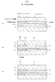
図3は、実施例3、比較例3、及び比較例4の端面の外観を示す図であり、(a)は実施例3の正面図、(b)は比較例3の正面図、(c)は比較例4の正面図である。ここでは、ホーリーファイバ50の空孔13を硬化性樹脂15で封止し、SCコネクタを取り付けており、フェルール21内に挿入されたホーリーファイバ50の端面とフェルール端面24を研磨処理した後のホーリーファイバ50の研磨端面を示している。
3A and 3B are views showing the outer appearances of the end surfaces of Example 3, Comparative Example 3, and Comparative Example 4. FIG. 3A is a front view of Example 3, FIG. 3B is a front view of Comparative Example 3, and FIG. ) Is a front view of Comparative Example 4. FIG. Here, the
図3(a)に示すように実施例3のホーリーファイバ50の研磨端面は、硬化性樹脂15のガラス接着強度7MPa、ショアD硬度82を用いて形成されており、空孔13と硬化性樹脂15の界面に剥離や研磨屑等の無い綺麗な面が得られている。
As shown in FIG. 3A, the polished end face of the
これに対して、図3(b)に示すように比較例3の研磨端面は、硬さが柔らかい硬化性樹脂15を用いることによって硬化性樹脂15の研磨屑150の堆積や空孔13との間に界面剥離151が発生した。また、図3(c)に示すように比較例4の研磨端面は、ガラス接着強度の低い硬化性樹脂15を用いたことにより空孔13と硬化性樹脂15の間に界面剥離151が発生している。
On the other hand, as shown in FIG. 3B, the polishing end surface of Comparative Example 3 uses a
図4は、実施例4、比較例5及び比較例6の封止部を示し、(a)は実施例4の縦断面図、(b)は比較例5の縦断面図、(c)は比較例6の縦断面図である。ここでは、ホーリーファイバ50の空孔13に体積収縮率、粘度の異なる硬化性樹脂15を充填、硬化させた充填部を視認できるように破断した縦断面を示している。
4 shows the sealing portions of Example 4, Comparative Example 5 and Comparative Example 6, wherein (a) is a longitudinal sectional view of Example 4, (b) is a longitudinal sectional view of Comparative Example 5, and (c) is FIG. It is a longitudinal cross-sectional view of the comparative example 6. Here, a longitudinal section is shown in which the
図4(a)に示す実施例4は、硬化性樹脂15が各空孔13に均一に充填され、空隙等の発生は見られない。これに対し、図4(b)に示す比較例5は、体積収縮率が高い硬化性樹脂15を用いた封止部に微小空隙である気泡15Aが発生している。また、図4(c)に示す比較例6は、粘度の高い硬化性樹脂15を用いた封止部に充填長の不均一が発生している。
In Example 4 shown in FIG. 4A, the
本実施例では、硬化性樹脂15として、屈折率がクラッド12の屈折率より低いものを用いている。硬化性樹脂15の屈折率がクラッド12より大きいと、樹脂を充填した空孔13が擬似コアとなり、伝送損失が生じ易くなるためである。ここで、硬化性樹脂15の屈折率は、SMF60の端面に硬化性樹脂15を塗布硬化させ、その端面で、波長1550nmで得られる反射減衰量から求めることができる。この場合の屈折率の温度特性は、反射減衰量の測定温度を変えることで求められる。
In this embodiment, a
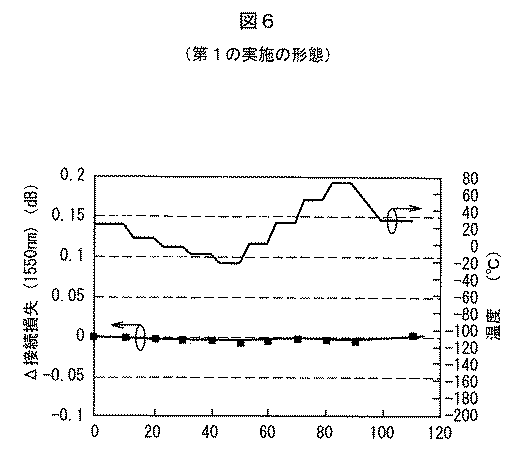
表1は、ホーリーファイバ50の空孔13に、クラッド12より屈折率の低い硬化性樹脂15を用いた実施例5と実施例6、及びクラッド12より屈折率が高い硬化性樹脂15を用いた比較例7にSCコネクタを取り付け、SMF60に汎用SCコネクタを取り付けた物と接続し、接続損失を測定した結果である。
Table 1 shows Examples 5 and 6 using a
表1から明らかなように、クラッド12より屈折率の低い硬化性樹脂15を用いた実施例5,6の接続損失が0.05〜0.2dBと小さいのに対し、クラッド12より屈折率の高い硬化性樹脂15を用いた比較例7は、接続損失が3dB以上になっている。
As is apparent from Table 1, the connection loss of Examples 5 and 6 using the
(光ファイバの接続構造)
図5は、本発明の実施の形態に係る光ファイバの接続構造を示す断面図である。図5に示すように、ホーリーファイバ50は、コア61とクラッド62からなる汎用のシングルモードファイバ(SMF)60と屈折率整合剤18を介して突き合わせ接続されている。ホーリーファイバ50は、光ファイバ端面14の近傍の空孔13に硬化性樹脂15が充填されている。なお、ホーリーファイバ50とSMF60の突き合わせ接続には、接続具として、例えば、メカニカルスプライスを用いる。
(Optical fiber connection structure)
FIG. 5 is a sectional view showing an optical fiber connection structure according to the embodiment of the present invention. As shown in FIG. 5, the
ここでは、硬化性樹脂15として、エポキシ系紫外線硬化樹脂(「UV・1100」ダイキン化学工業製)を使用した。この硬化性樹脂15は、粘度250mPa・s、透湿度0.2g/cm2・24h、屈折率1.449(λ=1550nm)、体積収縮率4%、ショアD82である。
Here, as the
光ファイバの接続方法について説明すると、まず、ホーリーファイバ50のUV被覆層をストリッパーで除去する。次に、ホーリーファイバ50の裸線が10mmとなる位置でファイバカッターを用いてホーリーファイバ50をカットする。
The optical fiber connecting method will be described. First, the UV coating layer of the
カットした後、硬化性樹脂15にホーリーファイバ50の端面を10秒間浸し、ホーリーファイバ50の空孔13内に硬化性樹脂を充填する。充填した後、ホーリーファイバ50の側面及び端面14に付着した硬化性樹脂をそれぞれガーゼ、コネクタクリーナで拭き取った。
After cutting, the end face of the
次に、光学顕微鏡によりホーリーファイバ50の側面を観察した。その結果、硬化性樹脂15はホーリーファイバ50の端面から各空孔13内に約300μmまで充填されていることを確認した。
Next, the side surface of the
次に、硬化性樹脂15を硬化させるため、紫外線照射装置(HOYA製:「EX250メタルハライドランプ」)で、側面より2000mJ/cm2の紫外線を硬化性樹脂15に照射して硬化させた。その後、メカニカルスプライスのガイド穴の一方にホーリーファイバ50を挿入し、他方のガイド穴に汎用SMF60を挿入し、ホーリーファイバ50と汎用SMF60の接続を行った。
Next, in order to cure the
図5の構成において、波長1550nmにおける接続損失は0.11dBであり、メカニカルスプライスによる接続を低損失に行うことができた。接続後、23±2℃、55%RHのもとで24時間経過しても、接続損失の変化はなかった。 In the configuration of FIG. 5, the connection loss at a wavelength of 1550 nm is 0.11 dB, and the connection by the mechanical splice can be performed with low loss. Even after 24 hours at 23 ± 2 ° C. and 55% RH after connection, there was no change in connection loss.
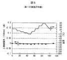
(光ファイバの接続損失特性)
図6は、図5の光ファイバの接続構造における接続損失特性を示す特性図である。図6は、図5のように接続されたホーリーファイバ50及びSMF60に波長1550nmの光信号を伝搬させると共に、その環境温度を−20〜+70℃内で変化させてホーリーファイバ50及びSMF60間の接続損失の変化を測定したものである。
(Connecting loss characteristics of optical fiber)
FIG. 6 is a characteristic diagram showing connection loss characteristics in the optical fiber connection structure of FIG. FIG. 6 shows a connection between the
図6において、Δ接続損失とは、測定開始直後の常温(約25℃)における接続損失を基準とした損失比を言う。図6に示すように、温度−20〜+70℃におけるΔ接続損失は、0.006dB以内と殆ど変化がなかった。接続後のホーリーファイバ50の側面を光学顕微鏡で観察すると、空孔13に充填された硬化性樹脂15により空孔13への屈折率整合剤18の浸入はなかった。
In FIG. 6, Δ connection loss refers to a loss ratio based on connection loss at room temperature (about 25 ° C.) immediately after the start of measurement. As shown in FIG. 6, the Δ connection loss at a temperature of −20 to + 70 ° C. was almost unchanged within 0.006 dB. When the side surface of the
これらの結果より、ホーリーファイバ50とSMF60のメカニカルスプライスによる接続において、本実施の形態の接続構造を形成することで、ホーリーファイバ50の空孔13への屈折率整合剤18の浸入を防ぎ、接続損失を低くし、かつ温度変化に対する接続損失の変動を微小にすることができる。
From these results, in the connection by the mechanical splice between the
以上、メカニカルスプライスを用いた光ファイバの接続方法について説明したが、本実施の形態に係る光ファイバの端面封止方法は、硬化による体積収縮率が5%以下で、かつ硬化前の25℃での粘度が5Pa・s以下である硬化性樹脂15をホーリーファイバ50に設けられる複数の空孔13の端部近傍に充填する工程と、充填された硬化性樹脂15を硬化させる工程とが含まれるものであれば、どのような接続方法であってもよい。
The optical fiber connection method using the mechanical splice has been described above. However, the end face sealing method of the optical fiber according to the present embodiment has a volume shrinkage due to curing of 5% or less and at 25 ° C. before curing. A step of filling the
(光コネクタの構成)
次に、本実施の形態の光ファイバを用いた光コネクタについて説明する。
(Configuration of optical connector)
Next, an optical connector using the optical fiber of the present embodiment will be described.
図7は、本発明の第2の実施の形態に係る光コネクタの断面図である。この光コネクタ100は、ホーリーファイバ50を固定する中空の固定部22及びフランジ26を備えたフェルール21と、ホーリーファイバ50のファイバ心線17を保持すると共にフェルール21に一体化されたファイバ保持部23と、を備えて構成されている。
FIG. 7 is a sectional view of an optical connector according to the second embodiment of the present invention. The
ホーリーファイバ50の空孔13には、硬化性樹脂15が充填されている。これにより、光ファイバ端面14及びフェルール端面24を研磨した際に生じる研磨屑が空孔13内に入り込むのが防止され、また、研磨屑に起因して、光コネクタ100の着脱時に光ファイバ端面14に割れや欠けが発生するのを防止することができる。
The
図8は、フェルール内に熱硬化性樹脂を充填した工程を示す断面図である。 FIG. 8 is a cross-sectional view showing a process of filling a ferrule with a thermosetting resin.
図9は、フェルールにホーリーファイバを固定した工程を示す断面図である。 FIG. 9 is a cross-sectional view showing a process of fixing the holey fiber to the ferrule.
次に、図8〜9を参照して、光コネクタの組立方法について説明する。
(光コネクタの組立方法)
Next, an optical connector assembling method will be described with reference to FIGS.
(Assembly method of optical connector)
まず、ホーリーファイバ50のUV被覆層をストリッパーで除去し、光ファイバ裸線が12±1mm(SCコネクタ対応)となる位置でホーリーファイバ50をファイバカッターでカットした。カットした後、ホーリーファイバ50の光ファイバ端面14を硬化性樹脂15に漬け、ホーリーファイバ50の空孔13内に硬化性樹脂15を5±1mm充填した。充填後、ホーリーファイバ50の光ファイバ端面14に付着した硬化性樹脂15を乾いたハイゼガーゼで拭き取った。
First, the UV coating layer of the
次に、光学顕微鏡により充填長を確認した後、硬化性樹脂15を硬化させるため、紫外線照射装置(HOYA製「EX250メタルハライドランプ」)で、側面より2000mJ/cm2の紫外線を照射して硬化し、ホーリーファイバ50を完成させた。
Next, after confirming the filling length with an optical microscope, in order to cure the
次に、図8に示すように、固定部22とファイバ保持部23に接着剤としての熱硬化性樹脂25を充填した。 Next, as shown in FIG. 8, the fixing portion 22 and the fiber holding portion 23 were filled with a thermosetting resin 25 as an adhesive.
次に、図9に示すように、上記のように空孔13内に硬化性樹脂15を充填済みのホーリーファイバ50を固定部22からファイバ保持部23に挿入する。
Next, as shown in FIG. 9, the
次に、ホーリーファイバ50が挿入されたフェルール21を85℃に保たれた恒温槽内に40分設置して熱硬化性樹脂25を硬化させ、ホーリーファイバ50をフェルール21に固定する。
Next, the ferrule 21 into which the
次に、図7に示すように、フェルール21のフェルール端面24の位置でホーリーファイバ50をカットした後、フェルール端面24及び光ファイバ端面14に研磨処理を施し、フェルール21をSCコネクタ用ハウジングに取り付け、ホーリーファイバ50のSC型の光コネクタ100を完成させた。
Next, as shown in FIG. 7, after the
以上のようにして組み立てた光コネクタ100と汎用のSCコネクタの着脱を500回繰り返したところ、光ファイバ端面14に欠けや傷等の損傷は見られなかった。すなわち、光ファイバ端面14の近傍の空孔13を硬化性樹脂15で封止したことで、空孔13内に侵入する研磨屑等の異物に起因する光ファイバ端面の損傷を防ぐことができる。
When the
すなわち、この製造方法によって製造された光コネクタは、気泡や剥離の発生が抑制されると共に、空孔13への研磨屑の進入を防止でき、長期信頼性の向上を図ることができる。
That is, in the optical connector manufactured by this manufacturing method, the occurrence of bubbles and peeling is suppressed, and it is possible to prevent the entry of polishing debris into the
[他の実施の形態]
なお、本発明は、上記各実施の形態に限定されず、本発明の技術思想を逸脱あるいは変更しない範囲内で種々な変形が可能である。
[Other embodiments]
The present invention is not limited to the above embodiments, and various modifications can be made without departing from or changing the technical idea of the present invention.
例えば、上記実施の形態においては、空孔13は、例えば6つであるが、これに限定されるものではない。例えば、数百個の空孔を有するPCF(ポリマー・クラッド・光ファイバ)を用いて光ファイバ、光コネクタを形成してもよい。また、空孔13の形状や配置等も限定されない。
For example, in the above embodiment, the number of the
更に、空孔13に充填する硬化性樹脂15の材質は、特に限定するものでない。例えば、純粋石英にGeが添加されてコアを形成するホーリーファイバ、PCFに関しては、純粋石英ガラスの屈折率と同等或いはそれ以下の屈折率を有し、硬化による透湿率が0.5g/cm2・24h以下、ガラス接着力5MPa以上、ショアD硬度50以上、体積収縮率が5%以下で、かつ硬化前の粘度が5Pa・s以下である硬化性樹脂15を用いることによって、同様の効果が得られる。
Further, the material of the
また、上記実施の形態では、光コネクタとしてSCコネクタを示したが、SCコネクタに限定されるものではなく、フェルール21にFC用ハウジングを取り付けてFCコネクタを形成してもよい。また、FCコネクタ、MU(Miniature Universal Coupling)コネクタ用のフェルールを用いてFCコネクタ、MUコネクタ等を形成してもよい。 Moreover, in the said embodiment, although SC connector was shown as an optical connector, it is not limited to SC connector, You may attach the housing for FC to the ferrule 21, and may form FC connector. Further, FC connectors, MU connectors, and the like may be formed using ferrules for FC connectors and MU (Miniature Universal Coupling) connectors.
また、上記実施の形態では、メカニカルスプライスによりホーリーファイバ50と汎用SMF60を接続したが、PCF或いはホーリーファイバ50等の空孔を有した光ファイバと接続される光ファイバは汎用SMF60に限らず、GI(Graded Index Fiber)ファイバやSI(Step Index Fiber)ファイバ等、汎用のマルチモードファイバ(MMF)でもよい。
In the above embodiment, the
また、硬化性樹脂15は、紫外線硬化樹脂、常温硬化性樹脂または熱硬化性樹脂を用いることができる。
The
11…コア、12…クラッド、13…空孔、14…光ファイバ端面、15…硬化性樹脂、15A…気泡、17…ファイバ心線、18…屈折率整合剤、21…フェルール、22…固定部、23…ファイバ保持部、24…フェルール端面、25…熱硬化性樹脂、26…フランジ、50…ホーリーファイバ(HF)、60…SMF(シングルモードファイバ)、61…コア、62…クラッド、100…光コネクタ、150…研磨屑、151…界面剥離
DESCRIPTION OF
Claims (12)
前記コアの周囲に設けられたクラッドと、
前記クラッドに設けられた複数の空孔と、
硬化後の透湿率が0.5g/cm2・24h以下の特性を有して前記空孔の端部近傍に充填された硬化性樹脂と、
を備えたことを特徴とする光ファイバ。 The core,
A clad provided around the core;
A plurality of holes provided in the cladding;
A curable resin having a property of moisture permeability after curing of 0.5 g / cm 2 · 24 h or less and filled in the vicinity of the end of the hole;
An optical fiber comprising:
前記コアの周囲に設けられたクラッドと、
前記クラッドに設けられた複数の空孔と、
ガラスとの接着強度が5MPa以上で硬化後の硬さがショアDで50以上の特性を有して前記空孔の端部近傍に充填された硬化性樹脂と、
を備えたことを特徴とする光ファイバ。 The core,
A clad provided around the core;
A plurality of holes provided in the cladding;
A curable resin having an adhesive strength with glass of 5 MPa or more and a hardness after curing having a property of Shore D of 50 or more and filled in the vicinity of the end of the hole;
An optical fiber comprising:
硬化後の透湿率が0.5g/cm2・24h以下の硬化性樹脂を前記光ファイバの前記複数の空孔の端部近傍に充填する第2の工程と、
充填された前記硬化性樹脂を硬化させる第3の工程と、
を備えたことを特徴とする光ファイバの端面封止方法。 A first step of preparing an optical fiber having a plurality of holes in the cladding;
A second step of filling a curable resin having a moisture permeability of 0.5 g / cm 2 · 24 h or less in the vicinity of ends of the plurality of holes of the optical fiber;
A third step of curing the filled curable resin;
An end face sealing method for an optical fiber, comprising:
ガラスとの接着強度が5MPa以上で硬化後の硬さがショアDで50以上である硬化性樹脂を前記光ファイバの前記複数の空孔の端部近傍に充填する第2の工程と、
充填された前記硬化性樹脂を硬化させる第3の工程と、
を備えたことを特徴とする光ファイバの端面封止方法。 A first step of preparing an optical fiber having a plurality of holes in the cladding;
A second step of filling the vicinity of the ends of the plurality of holes of the optical fiber with a curable resin having an adhesive strength with glass of 5 MPa or more and a hardness after curing of 50 or more on Shore D;
A third step of curing the filled curable resin;
An end face sealing method for an optical fiber, comprising:
Priority Applications (3)
| Application Number | Priority Date | Filing Date | Title |
|---|---|---|---|
| JP2007134772A JP2008287191A (en) | 2007-05-21 | 2007-05-21 | Optical fiber, end face sealing method of optical fiber, connecting structure of optical fiber, and optical connector |
| US11/984,287 US20080292244A1 (en) | 2007-05-21 | 2007-11-15 | Optical fiber, sealing method for optical fiber end face, connection structure of optical fiber, and optical connector |
| CNA2008100935047A CN101311757A (en) | 2007-05-21 | 2008-04-21 | Optical fiber, sealing method for optical fiber end face, connection structure of optical fiber, and optical connector |
Applications Claiming Priority (1)
| Application Number | Priority Date | Filing Date | Title |
|---|---|---|---|
| JP2007134772A JP2008287191A (en) | 2007-05-21 | 2007-05-21 | Optical fiber, end face sealing method of optical fiber, connecting structure of optical fiber, and optical connector |
Publications (1)
| Publication Number | Publication Date |
|---|---|
| JP2008287191A true JP2008287191A (en) | 2008-11-27 |
Family
ID=40072473
Family Applications (1)
| Application Number | Title | Priority Date | Filing Date |
|---|---|---|---|
| JP2007134772A Pending JP2008287191A (en) | 2007-05-21 | 2007-05-21 | Optical fiber, end face sealing method of optical fiber, connecting structure of optical fiber, and optical connector |
Country Status (3)
| Country | Link |
|---|---|
| US (1) | US20080292244A1 (en) |
| JP (1) | JP2008287191A (en) |
| CN (1) | CN101311757A (en) |
Cited By (2)
| Publication number | Priority date | Publication date | Assignee | Title |
|---|---|---|---|---|
| JP2011100046A (en) * | 2009-11-09 | 2011-05-19 | Hitachi Cable Ltd | Optical fiber, and method and apparatus for processing end of the same |
| KR101084716B1 (en) * | 2008-12-31 | 2011-11-22 | 전남대학교산학협력단 | Optical fiber having a mode block material and method for manufacturing the same |
Families Citing this family (7)
| Publication number | Priority date | Publication date | Assignee | Title |
|---|---|---|---|---|
| JP5479742B2 (en) * | 2007-01-24 | 2014-04-23 | 古河電気工業株式会社 | Fiber optic cable |
| CN101813629B (en) * | 2010-04-29 | 2011-09-28 | 大连海事大学 | Photonic crystal fiber chemical/biological sensing head and preparation method thereof |
| US20120141071A1 (en) * | 2010-12-07 | 2012-06-07 | Tyco Electronics Corporation | Optical connector |
| US10551566B2 (en) | 2014-02-21 | 2020-02-04 | Dow Silicones Corporation | Method of preparing an optical connector and optical devices comprising the optical connector prepared thereby |
| JP2018205387A (en) * | 2017-05-31 | 2018-12-27 | 矢崎総業株式会社 | Optical connector |
| CN108448365B (en) * | 2018-01-22 | 2019-06-25 | 航天科工防御技术研究试验中心 | A kind of contact pin of connector and the section preparation method of jack |
| JP7363820B2 (en) * | 2019-01-08 | 2023-10-18 | 住友電気工業株式会社 | Optical connector and its manufacturing method |
Citations (8)
| Publication number | Priority date | Publication date | Assignee | Title |
|---|---|---|---|---|
| JP2003004993A (en) * | 2001-06-22 | 2003-01-08 | Fujikura Ltd | Optical fiber |
| JP2004004320A (en) * | 2002-05-31 | 2004-01-08 | Mitsubishi Cable Ind Ltd | Photonic crystal fiber, method for producing the same and method for connecting the same |
| JP2004341297A (en) * | 2003-05-16 | 2004-12-02 | Hitachi Cable Ltd | Coated optical fiber |
| JP2005024846A (en) * | 2003-07-01 | 2005-01-27 | Hitachi Cable Ltd | Optical fibers, method of splicing optical fibers, and optical connector |
| JP2005031252A (en) * | 2003-07-09 | 2005-02-03 | Hitachi Cable Ltd | Optical fiber and optical fiber connector |
| JP2006126720A (en) * | 2004-11-01 | 2006-05-18 | Hitachi Cable Ltd | Optical fiber, method for sealing end face of optical fiber, connection structure of the optical fiber and optical connector |
| JP2006276882A (en) * | 2006-06-06 | 2006-10-12 | Sumitomo Electric Ind Ltd | End part structure of optical fiber and optical fiber |
| JP2007086536A (en) * | 2005-09-22 | 2007-04-05 | Nagase Chemtex Corp | Filler composition and method for manufacturing hole-assisted fiber using the same |
Family Cites Families (5)
| Publication number | Priority date | Publication date | Assignee | Title |
|---|---|---|---|---|
| US7125918B2 (en) * | 2000-11-07 | 2006-10-24 | Konica Corporation | Protective film of a polarizing plate |
| JP4329269B2 (en) * | 2001-02-07 | 2009-09-09 | 住友電気工業株式会社 | Optical fiber connection structure and optical fiber connection method |
| JP3870713B2 (en) * | 2001-04-25 | 2007-01-24 | 住友電気工業株式会社 | Optical fiber end structure and optical fiber |
| AU2002350398B2 (en) * | 2001-10-09 | 2007-11-22 | Crystal Fibre A/S | Hermetically sealed optical fibre with voids or holes, method of its production, and its use |
| US7376315B2 (en) * | 2003-07-01 | 2008-05-20 | Hitachi Cable, Ltd. | Optical fiber, optical fiber connecting method, and optical connector |
-
2007
- 2007-05-21 JP JP2007134772A patent/JP2008287191A/en active Pending
- 2007-11-15 US US11/984,287 patent/US20080292244A1/en not_active Abandoned
-
2008
- 2008-04-21 CN CNA2008100935047A patent/CN101311757A/en active Pending
Patent Citations (8)
| Publication number | Priority date | Publication date | Assignee | Title |
|---|---|---|---|---|
| JP2003004993A (en) * | 2001-06-22 | 2003-01-08 | Fujikura Ltd | Optical fiber |
| JP2004004320A (en) * | 2002-05-31 | 2004-01-08 | Mitsubishi Cable Ind Ltd | Photonic crystal fiber, method for producing the same and method for connecting the same |
| JP2004341297A (en) * | 2003-05-16 | 2004-12-02 | Hitachi Cable Ltd | Coated optical fiber |
| JP2005024846A (en) * | 2003-07-01 | 2005-01-27 | Hitachi Cable Ltd | Optical fibers, method of splicing optical fibers, and optical connector |
| JP2005031252A (en) * | 2003-07-09 | 2005-02-03 | Hitachi Cable Ltd | Optical fiber and optical fiber connector |
| JP2006126720A (en) * | 2004-11-01 | 2006-05-18 | Hitachi Cable Ltd | Optical fiber, method for sealing end face of optical fiber, connection structure of the optical fiber and optical connector |
| JP2007086536A (en) * | 2005-09-22 | 2007-04-05 | Nagase Chemtex Corp | Filler composition and method for manufacturing hole-assisted fiber using the same |
| JP2006276882A (en) * | 2006-06-06 | 2006-10-12 | Sumitomo Electric Ind Ltd | End part structure of optical fiber and optical fiber |
Cited By (3)
| Publication number | Priority date | Publication date | Assignee | Title |
|---|---|---|---|---|
| KR101084716B1 (en) * | 2008-12-31 | 2011-11-22 | 전남대학교산학협력단 | Optical fiber having a mode block material and method for manufacturing the same |
| JP2011100046A (en) * | 2009-11-09 | 2011-05-19 | Hitachi Cable Ltd | Optical fiber, and method and apparatus for processing end of the same |
| US8472769B2 (en) | 2009-11-09 | 2013-06-25 | Hitachi Cable, Ltd. | Optical fiber, end part processing method of optical fiber, and end part processing apparatus of optical fiber |
Also Published As
| Publication number | Publication date |
|---|---|
| US20080292244A1 (en) | 2008-11-27 |
| CN101311757A (en) | 2008-11-26 |
Similar Documents
| Publication | Publication Date | Title |
|---|---|---|
| JP2008287191A (en) | Optical fiber, end face sealing method of optical fiber, connecting structure of optical fiber, and optical connector | |
| WO2005003827A1 (en) | Optical fiber, optical fiber connecting method, and optical connector | |
| JP4877067B2 (en) | Optical fiber, optical fiber connection structure and optical connector | |
| JP2008164795A (en) | Optical connector | |
| US7555184B2 (en) | Optical fiber, end face structure of optical fiber assembly, and optical connector | |
| JP2011123398A (en) | Optical fiber, method of manufacturing the same and method of machining end part of optical fiber | |
| JP2008015183A (en) | Optical fiber holding structure and its manufacturing method | |
| JP4193889B2 (en) | Refractive index matching film forming method | |
| JP4096936B2 (en) | Optical fiber, optical fiber end face sealing method, optical fiber connection structure, and optical connector | |
| JP4918777B2 (en) | Optical waveguide connection structure | |
| JP2005024847A (en) | Connector for optical fibers | |
| JP4242903B2 (en) | Photonic crystal optical fiber, optical fiber connection method and optical connector | |
| JP3984569B2 (en) | Photonic crystal optical fiber | |
| JP2012108404A (en) | Optical fiber end structure and end processing method thereof | |
| JP2003294953A (en) | Optical device and method for manufacturing the same | |
| JP2005031252A (en) | Optical fiber and optical fiber connector | |
| JP2011191659A (en) | Optical fiber | |
| JPH09113763A (en) | Method for assembling optical connector | |
| JP2006011255A (en) | Optical connector ferrule and optical connector | |
| JP4482878B2 (en) | How to fix an optical fiber cable to a ferrule | |
| JP2011033784A (en) | Ferrule with optical fiber, and optical connector employing the same | |
| JP2007225743A (en) | Optical connector | |
| JP2011170107A (en) | Optical connector and manufacturing method thereof | |
| JP2009271312A (en) | Optical connection structure and optical connection method | |
| JP2004205970A (en) | Reinforcing structure for optical fiber exposed part |
Legal Events
| Date | Code | Title | Description |
|---|---|---|---|
| A621 | Written request for application examination |
Free format text: JAPANESE INTERMEDIATE CODE: A621 Effective date: 20090717 |
|
| A977 | Report on retrieval |
Free format text: JAPANESE INTERMEDIATE CODE: A971007 Effective date: 20100106 |
|
| A131 | Notification of reasons for refusal |
Free format text: JAPANESE INTERMEDIATE CODE: A131 Effective date: 20100810 |
|
| A02 | Decision of refusal |
Free format text: JAPANESE INTERMEDIATE CODE: A02 Effective date: 20101207 |