JP2008274694A - Unit building - Google Patents

Unit building Download PDF

Info

Publication number
JP2008274694A
JP2008274694A JP2007121705A JP2007121705A JP2008274694A JP 2008274694 A JP2008274694 A JP 2008274694A JP 2007121705 A JP2007121705 A JP 2007121705A JP 2007121705 A JP2007121705 A JP 2007121705A JP 2008274694 A JP2008274694 A JP 2008274694A
Authority
JP
Japan
Prior art keywords
floor
building unit
building
unit
columns
Prior art date
Legal status (The legal status is an assumption and is not a legal conclusion. Google has not performed a legal analysis and makes no representation as to the accuracy of the status listed.)
Granted
Application number
JP2007121705A
Other languages
Japanese (ja)
Other versions
JP5237575B2 (en
Inventor
Masaru Hashimoto
賢 橋本
Ryoji Kobashi
良治 小橋
Current Assignee (The listed assignees may be inaccurate. Google has not performed a legal analysis and makes no representation or warranty as to the accuracy of the list.)
Misawa Homes Co Ltd
Original Assignee
Misawa Homes Co Ltd
Priority date (The priority date is an assumption and is not a legal conclusion. Google has not performed a legal analysis and makes no representation as to the accuracy of the date listed.)
Filing date
Publication date
Application filed by Misawa Homes Co Ltd filed Critical Misawa Homes Co Ltd
Priority to JP2007121705A priority Critical patent/JP5237575B2/en
Publication of JP2008274694A publication Critical patent/JP2008274694A/en
Application granted granted Critical
Publication of JP5237575B2 publication Critical patent/JP5237575B2/en
Active legal-status Critical Current
Anticipated expiration legal-status Critical

Links

Images

Landscapes

  • Residential Or Office Buildings (AREA)

Abstract

<P>PROBLEM TO BE SOLVED: To provide a unit building in which the restriction of layout is reduced when a skip floor is constructed. <P>SOLUTION: This unit building comprises: first building units 31A, 31B having skeletons each formed of columns, ceiling beams one of which is partly broken, and floor beams and having intermediate floors 30 at the intermediate positions of the columns; second building units 32A, 32B disposed on the first building units 31A, 31B, respectively, having skeletons each formed of columns, ceiling beams one of which is partly broken, and floor beams one of which is partly broken, and having intermediate floors 30 at the intermediate positions of the columns; and standard lower story building unit 5 and upper story building unit 7 disposed adjacent to the first building units 31A, 31B and the second building units 32A, 32B in the horizontal direction, having generally rectangular parallelepiped skeletons, respectively, and having no intermediate floors at the intermediate positions of the columns. <P>COPYRIGHT: (C)2009,JPO&INPIT

Description

本発明は、柱、天井梁及び床梁を有する建物ユニットを複数組み合わせて建てられるユニット式建物に関する。   The present invention relates to a unit building constructed by combining a plurality of building units having columns, ceiling beams, and floor beams.

四隅に立設される4本の柱と、これらの柱の上端間同士または下端間同士をそれぞれ結合する各4本の天井梁、床梁を有する骨組みを備えた複数の建物ユニットを組み合わせて建てられるユニット式建物が知られている。
このユニット式建物には、一部の床面が他の床面と異なる高さレベルに設定されたスキップフロアを有するユニット式建物がある。
Built with a combination of four pillars standing at the four corners, and four building beams each having a frame with four ceiling beams and floor beams that connect the upper ends or lower ends of these columns. Unit type buildings are known.
In this unit type building, there is a unit type building having a skip floor in which a part of the floor surface is set at a different height level from the other floor surfaces.

このユニット式建物の従来例として、前記一部の床面を構成するスキップフロア建物ユニットと、前記他の床面を構成する標準建物ユニットと、これらの建物ユニットの間に配置されるスキップフロアジョイントユニットとを備えたものがある(特許文献1)。
このスキップフロアジョイントユニットは、スキップフロア建物ユニットを構成する柱の端部と、前記建物ユニットを構成する柱の端部とを連結する斜材を含んで構成される。
As a conventional example of this unit type building, the skip floor building unit constituting the part of the floor surface, the standard building unit constituting the other floor surface, and the skip floor joint disposed between these building units. Some have a unit (Patent Document 1).
The skip floor joint unit includes an oblique member that connects an end portion of a pillar constituting the skip floor building unit and an end portion of the pillar constituting the building unit.

特開2000−45391号公報(図1)JP 2000-45391 (FIG. 1)

特許文献1で示される従来例では、柱及び梁から直方体に形成された骨組みを有する建物ユニットを左右並びに上下に配置しなければならない。
そのため、建物ユニットは規格化されているので、隣り合う建物ユニットの床を上下にずらすには基礎の上に車庫等を設ける必要があり、レイアウトが制約されるという課題がある。
In the conventional example shown by patent document 1, the building unit which has the framework formed in the rectangular parallelepiped from the pillar and the beam must be arrange | positioned right and left and up and down.
Therefore, since the building units are standardized, it is necessary to provide a garage or the like on the foundation in order to shift the floors of adjacent building units up and down, and there is a problem that the layout is restricted.

本発明の目的は、スキップフロアを施工するにあたり、レイアウトの制約を少なくできるユニット式建物を提供することにある。   An object of the present invention is to provide a unit type building that can reduce layout restrictions when constructing a skip floor.

本発明のユニット式建物は、図面を参照して説明すると、4本の柱10と、これらの柱10の下端部同士を連結する4本の床梁13と、前記柱10の中間位置に設けられた中間床30と、前記柱10の上端部同士を連結する3本の天井梁12とを有し、前記天井梁12が設けられていない柱同士の間は天井梁欠損部とされた第1建物ユニット31A,31B,31C,31Dと、この第1建物ユニット31A,31B,31C,31Dの上に配置され、かつ、4本の柱10と、これらの柱10の下端部同士を連結する3本の床梁13と、前記柱10の中間位置に設けられた中間床30と、前記柱10の上端部同士を連結する3本の天井梁12とを有し、前記床梁13が設けられていない柱同士の間は床梁欠損部とされるとともに前記天井梁が設けられていない柱同士の間は天井梁欠損部とされた第2建物ユニット32A,32B,32C,32Dと、これらの第1建物ユニット31A,31B,31C,31Dと第2建物ユニット32A,32B,32C,32Dとの水平方向にそれぞれ隣接配置され、かつ、4本の柱10と、これらの柱10の下端部同士を連結する4本の床梁13と、前記柱10の上端部同士を連結する4本の天井梁12とを有し、前記柱10の中間位置には中間床が設けられていない標準建物ユニット4〜7と、を備えたことを特徴とする。   The unit type building of the present invention will be described with reference to the drawings. The four pillars 10, the four floor beams 13 connecting the lower ends of these pillars 10, and the middle position of the pillars 10 are provided. The intermediate floor 30 and the three ceiling beams 12 that connect the upper ends of the pillars 10 to each other, and between the columns where the ceiling beams 12 are not provided are the ceiling beam missing parts. 1 building unit 31A, 31B, 31C, 31D and this 1st building unit 31A, 31B, 31C, 31D are arrange | positioned, and the four pillars 10 and the lower end parts of these pillars 10 are connected. Three floor beams 13, an intermediate floor 30 provided at an intermediate position of the pillar 10, and three ceiling beams 12 that connect upper ends of the pillars 10, are provided. The gap between the pillars that are not made is a floor beam defect and the ceiling beam is The second building units 32A, 32B, 32C, and 32D, which are missing ceiling beams, are provided between the columns that are not arranged, and the first building units 31A, 31B, 31C, and 31D and the second building units 32A and 32B. , 32C, 32D, respectively, are arranged adjacent to each other in the horizontal direction, and four columns 10, four floor beams 13 connecting the lower ends of these columns 10, and upper ends of the columns 10 are connected to each other. It has four ceiling beams 12 to be connected, and standard building units 4 to 7 which are not provided with intermediate floors at intermediate positions of the pillars 10.

この発明によれば、第1建物ユニットと下階の標準建物ユニットとを配置し、この第1建物ユニットの上に第2建物ユニットを配置し、下階の標準建物ユニットの上に上階の標準建物ユニットを配置する。第1建物ユニットに天井梁欠損部が形成され、第2建物ユニットに天井梁欠損部及び床梁欠損部が形成されているので、下階の標準建物ユニットの床、第2建物ユニットの中間床、上階の標準建物ユニットの床及び第2建物ユニットの中間床がそれぞれ半階分ずつ高さの相違するスキップフロアが形成される。
従って、本発明では、スキップフロアを有するユニット式建物を施工するには、建物ユニットを組み合わせるだけでよく、車庫等を施工する必要がないので、レイアウトの自由性が確保できる。
According to this invention, the first building unit and the standard building unit on the lower floor are arranged, the second building unit is arranged on the first building unit, and the upper building is placed on the standard building unit on the lower floor. Place standard building units. Since the first building unit has a ceiling beam defect and the second building unit has a ceiling beam defect and a floor beam defect, the floor of the standard building unit on the lower floor and the intermediate floor of the second building unit The floors of the standard building unit on the upper floor and the intermediate floor of the second building unit are formed with skip floors having different heights by half the floor.
Therefore, in the present invention, in order to construct a unit type building having a skip floor, it is only necessary to combine the building units, and it is not necessary to construct a garage or the like, so that the freedom of layout can be ensured.

本発明では、前記第1建物ユニットは、前記中間床の下が収納空間とされている構成が好ましい。
この構成の発明では、第1建物ユニットの中間床より下方を収納空間としたので、限られたスペース内で収納空間を有効に形成することができる。
In the present invention, it is preferable that the first building unit has a storage space under the intermediate floor.
In the invention of this configuration, since the storage space is below the intermediate floor of the first building unit, the storage space can be effectively formed within the limited space.

前記第1建物ユニットと前記第2建物ユニットの少なくとも一方は、互いに並んで配置される2本の柱に対して中間柱が離れて配置され、これらの中間柱と前記柱との上下端部を連結する床梁及び天井梁とを含んで空間が形成される構成が好ましい。
この構成の発明では、第1建物ユニットと第2建物ユニットとの少なくとも一方のユニットに上下に区画されない空間が形成できるので、この空間を階段室、その他の空間として利用することで、スキップフロアを有する建物を有効に利用できる。
At least one of the first building unit and the second building unit is arranged such that an intermediate column is separated from two columns arranged side by side, and the upper and lower ends of the intermediate column and the column are arranged. A configuration in which a space is formed including the floor beam and the ceiling beam to be connected is preferable.
In the invention of this configuration, since a space that is not partitioned vertically can be formed in at least one of the first building unit and the second building unit, a skip floor can be formed by using this space as a staircase or other space. The building you have can be used effectively.

以下に、本発明の各実施形態を図面に基づいて説明する。
なお、以下の各実施形態の説明にあたって、同一構成要件については同一符号を付し、その説明を省略もしくは簡略化する。
Embodiments of the present invention will be described below with reference to the drawings.
In the following description of each embodiment, the same constituent elements are denoted by the same reference numerals, and the description thereof is omitted or simplified.

〔第1実施形態〕
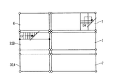
図1から図10には本発明の第1実施形態が示されている。図1は第1実施形態のユニット式建物1の概略を示す斜視図であり、図2は、図1中、II- II線に沿った軸組図であり、図3は図1中、III- III線に沿った軸組図であり、図4は1階天井の伏図であり、図5は、2階床の伏図である。
図1において、ユニット式建物1は、基礎2の上に設けられそれぞれ略直方体状の2個の第1建物ユニット31A,31Bと、これらの第1建物ユニット31A,31Bの長辺に並んで配置された下階建物ユニット4と、第1建物ユニット31A,31B及び下階建物ユニット4の短辺に並んで配置された下階建物ユニット5と、第1建物ユニット31A,31Bの上に配置された第2建物ユニット32A,32Bと、下階建物ユニット4,5の上にそれぞれ配置された上階建物ユニット6,7と、第2建物ユニット32A,32B及び上階建物ユニット6,7の上方に設けられた屋根8と、を備えて構成されている。
[First Embodiment]
1 to 10 show a first embodiment of the present invention. FIG. 1 is a perspective view showing an outline of a unit type building 1 according to the first embodiment, FIG. 2 is an axial view taken along line II-II in FIG. 1, and FIG. -Axis diagram along line III, Fig. 4 is a plan view of the first floor ceiling, and Fig. 5 is a plan view of the second floor.
In FIG. 1, a unit type building 1 is provided on a foundation 2 and is arranged in parallel with two first building units 31A and 31B each having a substantially rectangular parallelepiped shape and the long sides of these first building units 31A and 31B. The lower-floor building unit 4, the first building units 31A and 31B, the lower-floor building unit 5 arranged side by side on the short side of the lower-floor building unit 4, and the first building units 31A and 31B are disposed. The second building units 32A and 32B, the upper building units 6 and 7 respectively disposed on the lower building units 4 and 5, and the second building units 32A and 32B and the upper building units 6 and 7 above. And a roof 8 provided on the roof.

図2から図5において、第1建物ユニット31A及び第2建物ユニット32Aは建物の隅部に配置され、第1建物ユニット31B及び第2建物ユニット32Bは建物の真ん中に配置され、下階建物ユニット4及び上階建物ユニット6は第1建物ユニット31B及び第2建物ユニット32Bを挟んで第1建物ユニット31A及び第2建物ユニット32Aの反対側に配置されている。これらの建物ユニット31A,31B,32A,32B,4,6は外形形状が略同じである。下階建物ユニット5及び上階建物ユニット7は建物ユニット31A,31B,32A,32B,4,6と短辺方向の長さ及び高さ寸法が同じであるが、長辺方向の長さが建物ユニット31A,31B,32A,32B,4,6より長い。
これらの建物ユニット31A,31B,32A,32B,4,5,6、7は図示しない連結手段、例えば、プレートやボルト及びナットを介して互いに連結されている。なお、図2から図5において、第1建物ユニット31A及び第2建物ユニット32Aと第1建物ユニット31B及び第2建物ユニット32Bとの間は第1建物ユニット31B及び第2建物ユニット32Bと下階建物ユニット4及び上階建物ユニット6との間に比べて大きな隙間が形成されているが、図1では、その図示が省略されている。
2 to 5, the first building unit 31A and the second building unit 32A are arranged at the corners of the building, the first building unit 31B and the second building unit 32B are arranged in the middle of the building, and the lower floor building unit. 4 and the upper floor building unit 6 are arranged on the opposite side of the first building unit 31A and the second building unit 32A with the first building unit 31B and the second building unit 32B interposed therebetween. These building units 31A, 31B, 32A, 32B, 4 and 6 have substantially the same outer shape. The lower-floor building unit 5 and the upper-floor building unit 7 have the same length and height in the short side direction as the building units 31A, 31B, 32A, 32B, 4, 6, but the length in the long side direction is the building. It is longer than the units 31A, 31B, 32A, 32B, 4 and 6.
These building units 31A, 31B, 32A, 32B, 4, 5, 6, and 7 are connected to each other via connecting means (not shown) such as plates, bolts, and nuts. 2 to 5, the first building unit 31A, the second building unit 32A, and the first building unit 31B, the second building unit 32B are located between the first building unit 31B, the second building unit 32B, and the lower floor. A larger gap is formed between the building unit 4 and the upper floor building unit 6, but the illustration thereof is omitted in FIG. 1.

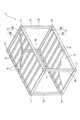
図6には、下階建物ユニット4の構成が示されている。図6において、下階建物ユニット4は、四隅に立設された4本の柱10と、これらの柱10の上端間同士を結合する各2本の長辺天井梁12A及び短辺天井梁12Bを含む天井梁12と、前記柱10の下端間同士を結合する各2本の長辺床梁13A及び短辺床梁13Bを含む床梁13とを有する骨組み14を備えて構成されている。これらの梁の端部同士は仕口11を介して互いに連結されている。建物ユニット4は居室等として利用される。
天井梁12の長辺天井梁12A間には、所定間隔で複数本の天井小梁15が架けわたされ、床梁13の長辺床梁13A間には、所定間隔で複数本の根太16が架けわたされている。そして、下階建物ユニット4等の骨組み14には、予め工場で、内壁や外壁(図示せず)、天井面材18や床面材19、その他の艤装部材等が取り付けられている。
下階建物ユニット5や上階建物ユニット6、7は下階建物ユニット4と略同一の構造であるので、詳細な説明は省略する。下階建物ユニット5及び上階建物ユニット7は下階建物ユニット4及び上階建物ユニット6に対して長辺天井梁12A及び長辺床梁13Aの長さが長い。下階建物ユニット4,5及び上階建物ユニット6、7は柱10の高さ寸法が標準高さとされる標準建物ユニットである。
FIG. 6 shows the configuration of the lower floor building unit 4. In FIG. 6, the lower-floor building unit 4 includes four pillars 10 erected at the four corners, and two long-side ceiling beams 12A and short-side ceiling beams 12B that connect the upper ends of these pillars 10 to each other. And a frame 14 having a floor beam 13 including two long-side floor beams 13A and a short-side floor beam 13B that connect the lower ends of the pillars 10 to each other. The ends of these beams are connected to each other through a joint 11. The building unit 4 is used as a living room or the like.
Between the long side ceiling beams 12A of the ceiling beam 12, a plurality of ceiling beams 15 are laid at a predetermined interval, and between the long side floor beams 13A of the floor beam 13, a plurality of joists 16 are provided at a predetermined interval. It is laid. In addition, an inner wall and an outer wall (not shown), a ceiling surface material 18 and a floor surface material 19, and other fitting members are attached to the framework 14 such as the lower-floor building unit 4 in advance at the factory.
Since the lower-floor building unit 5 and the upper-floor building units 6 and 7 have substantially the same structure as the lower-floor building unit 4, detailed description thereof is omitted. The lower floor building unit 5 and the upper floor building unit 7 are longer in the long side ceiling beam 12A and the long side floor beam 13A than the lower floor building unit 4 and the upper floor building unit 6. The lower-floor building units 4 and 5 and the upper-floor building units 6 and 7 are standard building units in which the height dimension of the pillar 10 is a standard height.

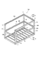
図7には第1建物ユニット31Aの構成が示されている。図7において、第1建物ユニット31Aは、4本の柱10と、これらの柱10の下端部同士を連結する4本の床梁13A,13Bと、柱10の中間位置に設けられた中間床30と、柱10の上端部同士を連結する3本の天井梁12A,12Bとを有し、天井梁が設けられていない柱10同士の間は天井梁欠損部とされた構成である。つまり、第1建物ユニット31Aは下階建物ユニット4の骨組み14に対して短辺天井梁12Bが1本欠損された構成である。この天井梁欠損部が下階建物ユニット5の短辺に対向される。
中間床30は、互いに対向する2本の長辺中間梁30Aと、互いに対向する2本の短辺中間梁30Bと、これらの中間梁30A,30Bの上に設けられた面材(図示せず)及び根太(図示せず)とを備えている。
中間床30の下方空間は収納スペースとされる。
FIG. 7 shows the configuration of the first building unit 31A. In FIG. 7, the first building unit 31 </ b> A includes four pillars 10, four floor beams 13 </ b> A and 13 </ b> B that connect the lower ends of these pillars 10, and an intermediate floor provided at an intermediate position between the pillars 10. 30 and the three ceiling beams 12A and 12B that connect the upper ends of the pillars 10 to each other, and the gap between the pillars 10 without the ceiling beams is a ceiling beam defect part. That is, the first building unit 31 </ b> A has a configuration in which one short-side ceiling beam 12 </ b> B is missing from the framework 14 of the lower-floor building unit 4. This missing portion of the ceiling beam is opposed to the short side of the lower floor building unit 5.
The intermediate floor 30 includes two long-side intermediate beams 30A facing each other, two short-side intermediate beams 30B facing each other, and a face material (not shown) provided on these intermediate beams 30A and 30B. ) And joists (not shown).
The space below the intermediate floor 30 is a storage space.

図8には第1建物ユニット31Aの上に配置される第2建物ユニット32Aの構成が示されている。図8において、第2建物ユニット32Aは4本の柱10と、これらの柱10の下端部同士を連結する3本の床梁13A,13Bと、柱10の中間位置に設けられた中間床30と、柱10の上端部同士を連結する3本の天井梁12A,12Bとを有し、天井梁が設けられていない柱10同士の間は天井梁欠損部とされ、かつ、床梁が設けられていない柱10同士の間は床梁欠損部とされた構成である。つまり、第2建物ユニット32Aは第1建物ユニット31Aの骨組み14に対して短辺床梁13Bが1本欠損されて床部が省略された構成である。この床部欠損部及び天井梁欠損部が上階建物ユニット7の短辺に対向される。
中間床30の下方空間は第1建物ユニット31Aの中間床30の上方空間と連続した居室空間とされ、第2建物ユニット32Aの中間床30の上方空間は小屋裏と連続した居室空間とされる。
第1建物ユニット31Aの上に第2建物ユニット32Aが配置され、第1建物ユニット31Aの天井梁欠損部に対向して下階建物ユニット5が配置され、第2建物ユニット31Aの天井梁欠損部及び床梁欠損部に対向した上階建物ユニット7が配置されることで、これらの建物ユニットの間に半階ずつ、ずれるスキップフロアが形成されることになる。
FIG. 8 shows the configuration of the second building unit 32A arranged on the first building unit 31A. In FIG. 8, the second building unit 32 </ b> A includes four pillars 10, three floor beams 13 </ b> A and 13 </ b> B that connect lower ends of these pillars 10, and an intermediate floor 30 provided at an intermediate position between the pillars 10. And three ceiling beams 12A and 12B that connect the upper ends of the pillars 10, between the pillars 10 where the ceiling beams are not provided are ceiling beam defects, and floor beams are provided. Between the pillars 10 which are not formed, it is the structure made into the floor beam defect | deletion part. That is, the second building unit 32A has a configuration in which one short side floor beam 13B is missing from the framework 14 of the first building unit 31A and the floor portion is omitted. The floor missing part and the ceiling beam missing part are opposed to the short side of the upper floor building unit 7.
The lower space of the intermediate floor 30 is a living room space continuous with the upper space of the intermediate floor 30 of the first building unit 31A, and the upper space of the intermediate floor 30 of the second building unit 32A is a living room space continuous with the back of the hut. .
The second building unit 32A is disposed on the first building unit 31A, the lower-floor building unit 5 is disposed opposite the ceiling beam defect portion of the first building unit 31A, and the ceiling beam defect portion of the second building unit 31A. And the upper floor building unit 7 facing the floor beam defect portion is arranged, so that a skip floor that is shifted by half a floor is formed between these building units.

図9には第1建物ユニット31Bの構成が示されている。図9において、第1建物ユニット31Bは、4本の柱10と、これらの柱10の下端部同士を連結する4本の床梁13A,13Bと、短辺方向に沿って配置された2本の柱10の略中間位置に配置された中間柱10Aと、2本の柱10及び2本の中間柱10Aの中間位置に設けられた中間床30と、柱10の上端部同士を連結する3本の天井梁12A,12Bと、短辺天井梁12Bが配置されていない短辺の中間柱10Aと柱10との上端部を連結する連結梁30Cと、中間柱10Aの上端部間を連結する連結梁30Dと、を有し、天井梁が設けられていない柱10同士の間は天井梁の一部が欠損された天井梁欠損部とされた構成である。この天井梁欠損部が下階建物ユニット5の短辺に対向される。中間床30の下方空間は収納スペースとされる。   FIG. 9 shows the configuration of the first building unit 31B. In FIG. 9, the first building unit 31 </ b> B includes four pillars 10, four floor beams 13 </ b> A and 13 </ b> B that connect lower ends of these pillars 10, and two arranged along the short side direction. 3 which connects the middle pillar 10A arrange | positioned in the substantially middle position of the pillar 10 of this, the intermediate | middle floor 30 provided in the middle position of the two pillars 10 and two middle pillar 10A, and the upper ends of the pillar 10 3 The ceiling beams 12A and 12B of the book, the connecting beam 30C that connects the upper ends of the short side intermediate column 10A and the column 10 where the short side ceiling beams 12B are not arranged, and the upper end of the intermediate column 10A are connected. The connecting beam 30D has a ceiling beam deficient portion in which a part of the ceiling beam is lost between the columns 10 having no connecting ceiling beam. This missing portion of the ceiling beam is opposed to the short side of the lower floor building unit 5. The space below the intermediate floor 30 is a storage space.

図10には、第1建物ユニット31Bの上に配置される第2建物ユニット32Bの構成が示されている。図10において、第2建物ユニット32Bは4本の柱10と、これらの柱10の下端部同士を連結する3本の床梁13A,13Bと、短辺方向に沿って配置された2本の柱10の略中間位置に配置された中間柱10Aと、2本の柱10及び2本の中間柱10Aの中間位置に設けられた中間床30と、柱10の上端部同士を連結する3本の天井梁12A,12Bと、短辺天井梁12Bが配置されていない短辺の中間柱10Aと柱10との上下端部をそれぞれ連結する連結梁30Cと、中間柱10Aの上下端部同士を連結する連結梁30Dと、を有する。この第2建物ユニット32Bでは、天井梁が設けられていない柱10同士の間が天井梁の一部が欠損された天井梁欠損部とされ、かつ、床梁が設けられていない柱10同士の間が床梁の一部が欠損された床梁欠損部とされた構成である。この天井梁欠損部及び床梁欠損部が上階建物ユニット7の短辺に対向される。   FIG. 10 shows the configuration of the second building unit 32B arranged on the first building unit 31B. In FIG. 10, the second building unit 32 </ b> B includes four pillars 10, three floor beams 13 </ b> A and 13 </ b> B that connect lower ends of these pillars 10, and two pieces arranged along the short side direction. Three intermediate pillars 10 </ b> A arranged at substantially intermediate positions of the pillars 10, the intermediate floor 30 provided at an intermediate position between the two pillars 10 and the two intermediate pillars 10 </ b> A, and the three upper ends of the pillars 10 are connected to each other. The connecting beams 30C that connect the upper and lower ends of the ceiling beams 12A and 12B, the short-side intermediate column 10A and the column 10 where the short-side ceiling beam 12B is not disposed, and the upper and lower ends of the intermediate column 10A are connected to each other. And a connecting beam 30D to be connected. In the second building unit 32B, a portion between the columns 10 not provided with the ceiling beam is a ceiling beam deficient portion in which a part of the ceiling beam is lost, and between the columns 10 without the floor beam provided. It is the structure made into the floor beam defect | deletion part from which a part of floor beam was missing in the space. The ceiling beam defect portion and the floor beam defect portion are opposed to the short side of the upper floor building unit 7.

第2建物ユニット32Bの中間床30の下方空間は第1建物ユニット31Bの中間床30の上方空間と連続した居室空間とされ、第2建物ユニット32Bの中間床30の上方空間は小屋裏と連続した居室空間とされる。
第1建物ユニット31Bの上に第2建物ユニット32Bが配置され、第1建物ユニット31Bの天井梁欠損部に対向して下階建物ユニット5が配置され、第2建物ユニット31Bの天井梁欠損部及び床梁欠損部に対向した上階建物ユニット7が配置されることで、これらの建物ユニットの間に半階ずつ、ずれるスキップフロアが形成されることになる。
第1建物ユニット31Bと第2建物ユニット32Bとには、それぞれ柱10、中間柱10A、天井梁12、床梁13及び連結梁30C,30Dで区画された空間から階段室が構成される。
The space below the intermediate floor 30 of the second building unit 32B is a living room space continuous with the space above the intermediate floor 30 of the first building unit 31B, and the space above the intermediate floor 30 of the second building unit 32B is continuous with the back of the hut. It is considered as a living room.
The second building unit 32B is disposed on the first building unit 31B, the lower-floor building unit 5 is disposed opposite the ceiling beam defect portion of the first building unit 31B, and the ceiling beam defect portion of the second building unit 31B. And the upper floor building unit 7 facing the floor beam defect portion is arranged, so that a skip floor that is shifted by half a floor is formed between these building units.
In the first building unit 31B and the second building unit 32B, a staircase is configured from a space defined by the column 10, the intermediate column 10A, the ceiling beam 12, the floor beam 13, and the connecting beams 30C and 30D.

以上のような第1実施形態によれば以下の効果がある。
(1)柱10、天井梁12及び床梁13から形成され1本の天井梁の少なくとも一部が欠損された骨組み14を有し柱10の中間位置に中間床30が設けられた第1建物ユニット31A,31Bと、この第1建物ユニット31A,32Aの上に配置され、かつ、柱10、天井梁12及び床梁13から形成され1本の天井梁と1本の床梁のそれぞれ少なくとも一部が欠損された骨組み14を有し柱10の中間位置に中間床30が設けられた第2建物ユニット32A,32Bと、これらの第1建物ユニット31A,31Bと第2建物ユニット32A,32Bとの水平方向にそれぞれ隣接配置され、かつ、略直方体状の骨組み14を有し、柱10の中間位置には中間床が設けられていない標準的な下階建物ユニット5及び上階建物ユニット7とを備えてユニット式建物を構成した。そのため、第1建物ユニット31A,31Bに天井梁欠損部が形成され、第2建物ユニット32A,32Bに天井梁欠損部及び床梁欠損部が形成されているので、これらのユニットの間で半階ずつ、ずれたスキップフロアが形成されることになり、スキップフロアを有するユニット式建物を施工するには、建物ユニットを組み合わせるだけでよいから、レイアウトの自由性を確保することができる。
The first embodiment as described above has the following effects.
(1) A first building having a frame 14 formed of a column 10, a ceiling beam 12, and a floor beam 13 in which at least a part of one ceiling beam is missing, and an intermediate floor 30 provided at an intermediate position of the column 10. Units 31A, 31B and the first building units 31A, 32A are arranged on the first building unit 31A, 32A, and are formed of the pillar 10, the ceiling beam 12, and the floor beam 13, and each of at least one ceiling beam and one floor beam. A second building unit 32A, 32B having a frame 14 with a missing part and an intermediate floor 30 provided at an intermediate position of the pillar 10, and the first building unit 31A, 31B and the second building unit 32A, 32B. Of the lower floor building unit 5 and the upper floor building unit 7 which are arranged adjacent to each other in the horizontal direction and have a substantially rectangular parallelepiped frame 14 and no intermediate floor is provided at the middle position of the pillar 10. Be equipped You configure the unit-type building Te. Therefore, the ceiling beam defect portion is formed in the first building units 31A and 31B, and the ceiling beam defect portion and the floor beam defect portion are formed in the second building units 32A and 32B. The shifted skip floors are formed one by one, and in order to construct the unit type building having the skip floor, it is only necessary to combine the building units, so that the freedom of layout can be ensured.

(2)第1建物ユニット31A,31Bは、中間床30の下が収納スペースとされているので、限られたスペース内で収納空間を有効に形成することができる。 (2) Since the first building units 31A and 31B have a storage space under the intermediate floor 30, the storage space can be effectively formed in a limited space.

(3)第1建物ユニット31B及び第2建物ユニット32Bは、互いに並んで配置される2本の柱10に対して中間柱10Aが離れて配置され、これらの中間柱10Aと柱10との上下端部を連結する床梁13及び天井梁12とを含んで空間が形成された構成である。そのため、第1建物ユニット31Bと第2建物ユニット32Bの双方に上下に区画されない空間が形成できるので、この空間を階段室として利用することで、隣接する下階建物ユニット5と第1建物ユニット31Bとの間や上階建物ユニット7と第2建物ユニット32Bとの間での通行を容易に行うことができる。しかも、下階建物ユニット5や上階建物ユニット7に階段室を設けることを要しないので、これらの建物ユニット5,7に広い居室空間を形成することができる。 (3) In the first building unit 31B and the second building unit 32B, the intermediate pillar 10A is arranged away from the two pillars 10 arranged side by side, and the upper and lower sides of the intermediate pillar 10A and the pillar 10 are arranged vertically. This is a configuration in which a space is formed including the floor beam 13 and the ceiling beam 12 connecting the end portions. Therefore, since the space which is not divided up and down can be formed in both the 1st building unit 31B and the 2nd building unit 32B, by using this space as a staircase, the adjacent lower floor building unit 5 and the 1st building unit 31B are used. And between the upper-floor building unit 7 and the second building unit 32B can be easily performed. And since it is not necessary to provide a staircase in the lower-floor building unit 5 or the upper-floor building unit 7, a wide living room space can be formed in these building units 5 and 7.

(4)第2建物ユニット32A,32Bの上方を吹き抜け空間としたので、小屋裏空間と連続した広い居室を形成することができる。
(5)第1建物ユニット31A,31Bを2個並べて配置し、第2建物ユニット32A,32Bを2個並べて配置したので、スキップフロアを有する居室空間を広く形成することができる。
(4) Since the space above the second building units 32A and 32B is used as a blow-off space, a large living room that is continuous with the cabin space can be formed.
(5) Since two first building units 31A and 31B are arranged side by side and two second building units 32A and 32B are arranged side by side, a room space having a skip floor can be formed widely.

〔第2実施形態〕
次に、本発明の第2実施形態を図11から図13に基づいて説明する。第2実施形態は主に、第1建物ユニット31Cと第2建物ユニット32Cとの構造が第1実施形態と異なり、他の構成は第1実施形態と略同じである。
図11は第2実施形態のユニット式建物1Aの概略を示す斜視図である。
図11において、ユニット式建物1Aは、基礎2の上に設けられた略直方体状の1個の第1建物ユニット31Cと、この第1建物ユニット31Cの短辺に並んで配置された下階建物ユニット4と、これらの建物ユニット31C,4の長辺にそれぞれ配置された下階建物ユニット4,5と、第1建物ユニット31Cの上に配置された第2建物ユニット32Cと、下階建物ユニット4,5の上にそれぞれ配置された上階建物ユニット6,7と、第2建物ユニット32C及び上階建物ユニット6,7の上方に設けられた屋根8と、を備えて構成されている。
[Second Embodiment]
Next, a second embodiment of the present invention will be described with reference to FIGS. The second embodiment is mainly different from the first embodiment in the structure of the first building unit 31C and the second building unit 32C, and other configurations are substantially the same as those in the first embodiment.
FIG. 11 is a perspective view showing an outline of a unit building 1A of the second embodiment.
In FIG. 11, the unit type building 1 </ b> A includes a first building unit 31 </ b> C having a substantially rectangular parallelepiped shape provided on the foundation 2, and a lower-floor building arranged side by side on the short side of the first building unit 31 </ b> C. Unit 4, lower-floor building units 4 and 5 disposed on the long sides of these building units 31C and 4, respectively, second building unit 32C disposed on first building unit 31C, and lower-floor building unit 4 and 5 and upper roof building units 6 and 7 and a roof 8 provided above the second building unit 32C and upper floor building units 6 and 7, respectively.

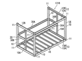
図12には第1建物ユニット31Cの構成が示されている。図12において、第1建物ユニット31Cは、4本の柱10と、これらの柱10の下端部同士を連結する4本の床梁13A,13Bと、長辺方向に沿って配置された2本の柱10の略中間位置に配置された中間柱10Aと、2本の柱10及び2本の中間柱10Aの中間位置に設けられた中間床30と、柱10の上端部同士を連結する3本の天井梁12A,12Bと、長辺天井梁12Aが配置されていない短辺の中間柱10Aと柱10との上端部を連結する連結梁30Cと、中間柱10Aの上端部同士を連結する連結梁30Dとを有し、天井梁が設けられていない柱10同士の間は天井梁の一部が欠損された天井梁欠損部とされた構成である。この天井梁欠損部が下階建物ユニット5の長辺に対向される。
中間床30の下方空間は収納スペースとされる。なお、互いに対向する長辺床梁13Aには根太16が連結されている。第1建物ユニット31Cの長辺天井梁12A及び長辺床梁13Aは第1実施形態における第1建物ユニット31Aの長辺天井梁12A及び長辺床梁13Aより長く形成されている。
FIG. 12 shows the configuration of the first building unit 31C. In FIG. 12, the first building unit 31 </ b> C includes four pillars 10, four floor beams 13 </ b> A and 13 </ b> B that connect lower ends of these pillars 10, and two arranged along the long side direction. 3 which connects the middle pillar 10A arrange | positioned in the substantially middle position of the pillar 10 of this, the intermediate | middle floor 30 provided in the middle position of the two pillars 10 and two middle pillar 10A, and the upper ends of the pillar 10 3 The ceiling beams 12A and 12B of the book, the connecting beam 30C that connects the upper ends of the short-side intermediate column 10A and the column 10 where the long-side ceiling beam 12A is not disposed, and the upper ends of the intermediate column 10A are connected to each other. Between the pillars 10 having the connecting beam 30D and not provided with the ceiling beam, the ceiling beam lacking part in which a part of the ceiling beam is missing is formed. This missing portion of the ceiling beam is opposed to the long side of the lower floor building unit 5.
The space below the intermediate floor 30 is a storage space. A joist 16 is connected to the long side floor beams 13A facing each other. The long side ceiling beam 12A and the long side floor beam 13A of the first building unit 31C are formed longer than the long side ceiling beam 12A and the long side floor beam 13A of the first building unit 31A in the first embodiment.

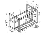
図13には第1建物ユニット31Cの上に配置される第2建物ユニット32Cの構成が示されている。図13において、第2建物ユニット32Cは、4本の柱10と、これらの柱10の下端部同士を連結する4本の床梁13A,13Bと、長辺方向に沿って配置された2本の柱10の略中間位置に配置された中間柱10Aと、2本の柱10及び2本の中間柱10Aの中間位置に設けられた中間床30と、柱10の上端部同士を連結する3本の天井梁12A,12Bと、長辺天井梁12Aが配置されていない短辺の中間柱10Aと柱10との上端部を連結する連結梁30Cと、中間柱10Aの上下端部同士を連結する連結梁30Dと、を有し、天井梁が設けられていない柱10同士の間が天井梁の一部が欠損された天井梁欠損部とされ、かつ、床梁が設けられていない柱10同士の間が床梁の一部が欠損された床梁欠損部とされた構成である。この天井梁欠損部及び床梁欠損部が上階建物ユニット7の長辺に対向される。
中間床30の下方空間は第1建物ユニット31Cの中間床30の上方空間と連続した居室空間とされ、第2建物ユニット32Cの中間床30の上方空間は小屋裏と連続した居室空間とされる。
FIG. 13 shows the configuration of the second building unit 32C arranged on the first building unit 31C. In FIG. 13, the second building unit 32 </ b> C includes four pillars 10, four floor beams 13 </ b> A and 13 </ b> B that connect lower ends of these pillars 10, and two arranged along the long side direction. The intermediate pillar 10A arranged at a substantially middle position of the pillar 10 of the present invention, the intermediate floor 30 provided at the middle position of the two pillars 10 and the two intermediate pillars 10A, and the upper ends of the pillars 10 are connected 3 The ceiling beams 12A and 12B of the book, the connecting beam 30C that connects the upper ends of the short side intermediate column 10A and the column 10 where the long side ceiling beam 12A is not disposed, and the upper and lower ends of the intermediate column 10A are connected to each other. A column 10 having a connecting beam 30D and a column 10 having no ceiling beam and having no ceiling beam between the columns 10 having no ceiling beam. The space between them is a floor beam defect part in which a part of the floor beam is lost. The ceiling beam defect portion and the floor beam defect portion are opposed to the long side of the upper floor building unit 7.
The lower space of the intermediate floor 30 is a living room space continuous with the upper space of the intermediate floor 30 of the first building unit 31C, and the upper space of the intermediate floor 30 of the second building unit 32C is a living room space continuous with the back of the hut. .

第1建物ユニット31Cの上に第2建物ユニット32Cが配置され、第1建物ユニット31Cの天井梁欠損部に対向して下階建物ユニット5が配置され、第2建物ユニット31Cの天井梁欠損部及び床梁欠損部に対向して上階建物ユニット7が配置されることで、これらの建物ユニットの間に半階ずつ、ずれるスキップフロアが形成されることになる。
第1建物ユニット31Cと第2建物ユニット32Cとには、それぞれ柱10、中間柱10A、天井梁12、床梁13及び連結梁30C,30Dで区画された空間から階段室が構成される。
従って、第2実施形態では、第1実施形態の(1)〜(4)と同様の効果を奏することができる。
The second building unit 32C is disposed on the first building unit 31C, the lower-floor building unit 5 is disposed opposite the ceiling beam defect portion of the first building unit 31C, and the ceiling beam defect portion of the second building unit 31C. By arranging the upper floor building unit 7 so as to face the floor beam defect portion, a skip floor that is shifted by half a floor is formed between these building units.
In the first building unit 31C and the second building unit 32C, a staircase is configured from a space defined by the column 10, the intermediate column 10A, the ceiling beam 12, the floor beam 13, and the connecting beams 30C and 30D.
Therefore, in the second embodiment, the same effects as (1) to (4) of the first embodiment can be achieved.

〔第3実施形態〕
次に、本発明の第3実施形態を図14から図15に基づいて説明する。第3実施形態は第1建物ユニット31Dと第2建物ユニット32Dとの構造が第2実施形態と異なり、他の構成は第1実施形態と略同じである。
第3実施形態では、第1建物ユニット31Dが第2実施形態の第1建物ユニット31Cの位置に配置され、第2建物ユニット32Dが第2実施形態の第2建物ユニット31Cの位置に配置されている。
[Third Embodiment]
Next, a third embodiment of the present invention will be described with reference to FIGS. The third embodiment is different from the second embodiment in the structure of the first building unit 31D and the second building unit 32D, and the other configurations are substantially the same as those of the first embodiment.
In the third embodiment, the first building unit 31D is arranged at the position of the first building unit 31C of the second embodiment, and the second building unit 32D is arranged at the position of the second building unit 31C of the second embodiment. Yes.

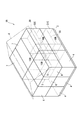
図14には第1建物ユニット31Dの構成が示されている。図14において、第1建物ユニット31Dは、4本の柱10と、これらの柱10の下端部同士を連結する4本の床梁13A,13Bと、互いに隣り合う柱10の間の略中間位置を含む平面矩形状の3箇所の角部にそれぞれ配置された中間柱10Aと、1本の柱10と3本の中間柱10Aの中間位置に設けられた中間床30と、柱10の上端部同士を連結する3本の天井梁12A,12Bと、長辺天井梁12Aが配置されていない短辺の中間柱10Aと柱10との上端部を連結する連結梁30Cと、中間柱10Aの上端部同士を連結する連結梁30Dとを有し、天井梁が設けられていない柱10同士の間は天井梁の一部が欠損された天井梁欠損部とされた構成である。この第1建物ユニット31Dは中間床30を除く平面L字形の空間が形成され、この空間は柱10に対応した高さを有するものであり、階段室や居室として利用される。   FIG. 14 shows the configuration of the first building unit 31D. In FIG. 14, the first building unit 31 </ b> D is a substantially intermediate position between the four pillars 10, the four floor beams 13 </ b> A and 13 </ b> B that connect the lower ends of these pillars 10, and the pillars 10 adjacent to each other. 10 A of intermediate pillars each arrange | positioned at the corner | angular part of two plane rectangles containing the intermediate | middle floor 30 provided in the intermediate position of one pillar 10 and three intermediate pillars 10A, and the upper end part of the pillar 10 Three ceiling beams 12A and 12B that connect each other, a connecting beam 30C that connects the upper ends of the short-side intermediate column 10A and the column 10 where the long-side ceiling beam 12A is not disposed, and the upper end of the intermediate column 10A It has a configuration in which a ceiling beam deficient part in which a part of the ceiling beam is missing is provided between the columns 10 having the connecting beam 30D for connecting the parts and the ceiling beam not provided. The first building unit 31D is formed with a plane L-shaped space excluding the intermediate floor 30, and this space has a height corresponding to the pillar 10, and is used as a staircase or a living room.

図15には第1建物ユニット31Dの上に配置される第2建物ユニット32Dの構成が示されている。図15において、第2建物ユニット32Dは、4本の柱10と、これらの柱10の下端部同士を連結する4本の床梁13A,13Bと、互いに隣り合う柱10の間の略中間位置を含む平面矩形状の3箇所の角部にそれぞれ配置された中間柱10Aと、1本の柱10及び3本の中間柱10Aの中間位置に設けられた中間床30と、柱10の上端部同士を連結する3本の天井梁12A,12Bと、長辺天井梁12Aが配置されていない短辺の中間柱10Aと柱10との上端部を連結する連結梁30Cと、中間柱10Aの上下端部同士を連結する連結梁30Dと、を有し、天井梁が設けられていない柱10同士の間が天井梁の一部が欠損された天井梁欠損部とされ、かつ、床梁が設けられていない柱10同士の間が床梁の一部が欠損された床梁欠損部とされた構成である。この天井梁欠損部及び床梁欠損部が上階建物ユニット7の長辺に対向される。
中間床30の下方空間は第1建物ユニット31Dの中間床30の上方空間と連続した居室空間とされ、第2建物ユニット32Dの中間床30の上方空間は小屋裏と連続した居室空間とされる。
FIG. 15 shows the configuration of the second building unit 32D arranged on the first building unit 31D. In FIG. 15, the second building unit 32 </ b> D is a substantially intermediate position between the four pillars 10, the four floor beams 13 </ b> A and 13 </ b> B connecting the lower ends of these pillars 10, and the pillars 10 adjacent to each other. The intermediate pillars 10A respectively disposed at three corners of the plane rectangular shape including the intermediate pillar 30 provided at an intermediate position between the one pillar 10 and the three intermediate pillars 10A, and the upper end of the pillar 10 Three ceiling beams 12A and 12B that connect each other, a connecting beam 30C that connects upper ends of the short side intermediate column 10A and the column 10 on which the long side ceiling beam 12A is not disposed, and upper and lower sides of the intermediate column 10A A connecting beam 30D for connecting the end portions to each other, a portion between the columns 10 without the ceiling beam being a ceiling beam deficient portion in which a part of the ceiling beam is lost, and a floor beam is provided Floor beam defect in which part of the floor beam is missing between the pillars 10 that are not It is the configuration. The ceiling beam defect portion and the floor beam defect portion are opposed to the long side of the upper floor building unit 7.
The lower space of the intermediate floor 30 is a living room space continuous with the upper space of the intermediate floor 30 of the first building unit 31D, and the upper space of the intermediate floor 30 of the second building unit 32D is a living room space continuous with the back of the hut. .

第1建物ユニット31Dの上に第2建物ユニット32Dが配置され、第1建物ユニット31Dの天井梁欠損部に対向して下階建物ユニット5が配置され、第2建物ユニット31Dの天井梁欠損部及び床梁欠損部に対向して上階建物ユニット7が配置されることで、これらの建物ユニットの間に半階ずつ、ずれるスキップフロアが形成されることになる。
従って、第3実施形態では、第1実施形態の(1)〜(4)と同様の効果を奏することができる。
The second building unit 32D is disposed on the first building unit 31D, the lower-floor building unit 5 is disposed opposite the ceiling beam defect portion of the first building unit 31D, and the ceiling beam defect portion of the second building unit 31D. By arranging the upper floor building unit 7 so as to face the floor beam defect portion, a skip floor that is shifted by half a floor is formed between these building units.
Therefore, in the third embodiment, the same effects as (1) to (4) of the first embodiment can be obtained.

なお、本発明は前記各実施形態に限定されるものではなく、本発明の目的を達成できる範囲での変形、改良等は本発明に含まれるものである。
例えば、前記各実施形態では、平面矩形状の建物ユニットの短辺梁を欠損して第1建物ユニット31A,31B,31C,31D及び第2建物ユニット32A,32B,32C,32Dを形成したが、本発明では、図16から図19に示されるように、建物ユニットの長辺梁を欠損して第1建物ユニット及び第2建物ユニットを形成し、これらの建物ユニットの長辺側に標準建物ユニットの長辺を配置してユニット式建物を施工するものでもよい。
Note that the present invention is not limited to the above-described embodiments, and modifications, improvements, and the like within the scope in which the object of the present invention can be achieved are included in the present invention.
For example, in each of the above embodiments, the first building units 31A, 31B, 31C, and 31D and the second building units 32A, 32B, 32C, and 32D are formed by deleting the short side beams of the planar rectangular building unit. In the present invention, as shown in FIGS. 16 to 19, the first building unit and the second building unit are formed by deleting the long side beams of the building unit, and the standard building unit is formed on the long side of these building units. The unit type building may be constructed by arranging the long sides.

すなわち、図7に示される第1建物ユニット31Aに代えて図16で示される第1建物ユニット131Aを用い、図8に示される第2建物ユニット32Aに代えて図17で示される第1建物ユニット132Aを用いる。この際、第1建物ユニット131Aの長辺側に形成された天井梁欠損部が下階建物ユニット4の長辺に対向される。同様に、第2建物ユニット132Aの長辺側に形成された天井梁欠損部が上階建物ユニット6の長辺に対向される。
また、図9に示される第1建物ユニット31Bに代えて図18で示される第1建物ユニット131Bを用い、図10に示される第2建物ユニット32Bに代えて図19で示される第1建物ユニット132Bを用いる。この際、第1建物ユニット131Bの長辺側に形成された天井梁欠損部が下階建物ユニット4の長辺に対向される。同様に、第2建物ユニット132Bの長辺側に形成された天井梁欠損部が上階建物ユニット6の長辺に対向される。
That is, instead of the first building unit 31A shown in FIG. 7, the first building unit 131A shown in FIG. 16 is used, and instead of the second building unit 32A shown in FIG. 8, the first building unit shown in FIG. 132A is used. At this time, the ceiling beam defect portion formed on the long side of the first building unit 131 </ b> A is opposed to the long side of the lower floor building unit 4. Similarly, the ceiling beam defect portion formed on the long side of the second building unit 132 </ b> A is opposed to the long side of the upper floor building unit 6.
Further, the first building unit 131B shown in FIG. 18 is used instead of the first building unit 31B shown in FIG. 9, and the first building unit shown in FIG. 19 is used instead of the second building unit 32B shown in FIG. 132B is used. At this time, the ceiling beam defect portion formed on the long side of the first building unit 131 </ b> B is opposed to the long side of the lower building unit 4. Similarly, the ceiling beam defect portion formed on the long side of the second building unit 132 </ b> B is opposed to the long side of the upper floor building unit 6.

さらに、前記各実施形態では、2階建ての建物であるが、本発明は3階以上の建物にも適用することができる。   Furthermore, in each said embodiment, although it is a 2 story building, this invention is applicable also to a 3 or more-story building.

本発明は、住宅等の建物や、店舗等の建物に利用できる。   The present invention can be used for buildings such as houses and buildings such as stores.

本発明の第1実施形態に係るユニット式建物を示す斜視図。The perspective view which shows the unit type building which concerns on 1st Embodiment of this invention. 図1中、II-II線に沿った軸組図。FIG. 2 is an axis diagram along line II-II in FIG. 図1中、III-III線に沿った軸組図。FIG. 3 is an axial diagram along line III-III in FIG. 1. 1階天井の伏図。A sketch of the first floor ceiling. 2階床の伏図。The floor plan of the second floor. 下階建物ユニットの骨組みを示す斜視図。The perspective view which shows the framework of a lower-floor building unit. 第1建物ユニットの骨組みを示す斜視図。The perspective view which shows the framework of a 1st building unit. 第2建物ユニットの骨組みを示す斜視図。The perspective view which shows the framework of a 2nd building unit. 第1建物ユニットの骨組みを示す斜視図。The perspective view which shows the framework of a 1st building unit. 第2建物ユニットの骨組みを示す斜視図。The perspective view which shows the framework of a 2nd building unit. 本発明の第2実施形態に係るユニット式建物を示す斜視図。The perspective view which shows the unit type building which concerns on 2nd Embodiment of this invention. 第1建物ユニットの骨組みを示す斜視図。The perspective view which shows the framework of a 1st building unit. 第2建物ユニットの骨組みを示す斜視図。The perspective view which shows the framework of a 2nd building unit. 本発明の第3実施形態における第1建物ユニットの骨組みを示す斜視図。The perspective view which shows the framework of the 1st building unit in 3rd Embodiment of this invention. 第2建物ユニットの骨組みを示す斜視図。The perspective view which shows the framework of a 2nd building unit. 本発明の変形例にかかる第1建物ユニットの骨組みを示す斜視図。The perspective view which shows the framework of the 1st building unit concerning the modification of this invention. 本発明の変形例にかかる第2建物ユニットの骨組みを示す斜視図。The perspective view which shows the framework of the 2nd building unit concerning the modification of this invention. 本発明の変形例にかかる第1建物ユニットの骨組みを示す斜視図。The perspective view which shows the framework of the 1st building unit concerning the modification of this invention. 本発明の変形例にかかる第2建物ユニットの骨組みを示す斜視図。The perspective view which shows the framework of the 2nd building unit concerning the modification of this invention.

符号の説明Explanation of symbols

1,1A ユニット式建物
31A,31B,31C,31D,131A,131B 第1建物ユニット
32A,32B,32C,32D,132A,132B 第2建物ユニット
4,5 下階建物ユニット(標準建物ユニット)
6,7 上階建物ユニット(標準建物ユニット)
8 屋根
10 柱
10A 中間柱
12,12A,12B 天井梁
13,13A,13B 床梁
30 中間床
1,1A Unit type building 31A, 31B, 31C, 31D, 131A, 131B First building unit 32A, 32B, 32C, 32D, 132A, 132B Second building unit 4,5 Lower floor building unit (standard building unit)
6,7 Upper floor building unit (standard building unit)
8 Roof 10 Column 10A Intermediate column 12, 12A, 12B Ceiling beam 13, 13A, 13B Floor beam 30 Intermediate floor

Claims (3)

4本の柱と、これらの柱の下端部同士を連結する4本の床梁と、前記柱の中間位置に設けられた中間床と、前記柱の上端部同士を連結する3本の天井梁とを有し、前記天井梁が設けられていない柱同士の間は天井梁欠損部とされた第1建物ユニットと、
この第1建物ユニットの上に配置され、かつ、4本の柱と、これらの柱の下端部同士を連結する3本の床梁と、前記柱の中間位置に設けられた中間床と、前記柱の上端部同士を連結する3本の天井梁とを有し、前記床梁が設けられていない柱同士の間は床梁欠損部とされるとともに前記天井梁が設けられていない柱同士の間は天井梁欠損部とされた第2建物ユニットと、
これらの第1建物ユニットと第2建物ユニットとの水平方向にそれぞれ隣接配置され、かつ、4本の柱と、これらの柱の下端部同士を連結する4本の床梁と、前記柱の上端部同士を連結する4本の天井梁とを有し、前記柱の中間位置には中間床が設けられていない標準建物ユニットと、
を備えたことを特徴とするユニット式建物。
4 columns, 4 floor beams connecting the lower ends of these columns, an intermediate floor provided at an intermediate position of the columns, and 3 ceiling beams connecting the upper ends of the columns And a first building unit between the columns not provided with the ceiling beam is a ceiling beam deficient portion,
Arranged on the first building unit, and four pillars, three floor beams connecting the lower ends of these pillars, an intermediate floor provided at an intermediate position of the pillars, And three ceiling beams that connect the upper ends of the columns, and between the columns that are not provided with the floor beam are floor beam deficient portions and between the columns that are not provided with the ceiling beam. Between the second building unit between the ceiling beam defects,
The first building unit and the second building unit are respectively arranged adjacent to each other in the horizontal direction, and four columns, four floor beams connecting the lower ends of these columns, and the upper ends of the columns A standard building unit having four ceiling beams that connect the parts, and no intermediate floor is provided at an intermediate position of the pillar;
A unit type building characterized by comprising
請求項1に記載されたユニット式建物において、
前記第1建物ユニットは、前記中間床の下が収納空間とされていることを特徴とするユニット式建物。
In the unit type building according to claim 1,
The first building unit is a unit type building characterized in that a storage space is provided under the intermediate floor.
請求項1又は請求項2に記載されたユニット式建物において、
前記第1建物ユニットと前記第2建物ユニットとの少なくとも一方は、互いに並んで配置される2本の柱に対して中間柱が離れて配置され、これらの中間柱と前記柱との上下端部を連結する床梁及び天井梁とを含んで空間が形成されることを特徴とするユニット式建物。
In the unit type building according to claim 1 or 2,
At least one of the first building unit and the second building unit is arranged such that an intermediate column is separated from two columns arranged side by side, and upper and lower ends of the intermediate column and the column. A unit type building characterized in that a space is formed including a floor beam and a ceiling beam connecting the two.
JP2007121705A 2007-05-02 2007-05-02 Unit building Active JP5237575B2 (en)

Priority Applications (1)

Application Number Priority Date Filing Date Title
JP2007121705A JP5237575B2 (en) 2007-05-02 2007-05-02 Unit building

Applications Claiming Priority (1)

Application Number Priority Date Filing Date Title
JP2007121705A JP5237575B2 (en) 2007-05-02 2007-05-02 Unit building

Publications (2)

Publication Number Publication Date
JP2008274694A true JP2008274694A (en) 2008-11-13
JP5237575B2 JP5237575B2 (en) 2013-07-17

Family

ID=40052984

Family Applications (1)

Application Number Title Priority Date Filing Date
JP2007121705A Active JP5237575B2 (en) 2007-05-02 2007-05-02 Unit building

Country Status (1)

Country Link
JP (1) JP5237575B2 (en)

Cited By (4)

* Cited by examiner, † Cited by third party
Publication number Priority date Publication date Assignee Title
JP2011084904A (en) * 2009-10-14 2011-04-28 Asahi Kasei Homes Co Skip floor-type building
JP2012007291A (en) * 2010-06-22 2012-01-12 Misawa Homes Co Ltd Building unit
JP2018168574A (en) * 2017-03-29 2018-11-01 トヨタホーム株式会社 Building unit and unit type building
JP7415505B2 (en) 2019-12-06 2024-01-17 トヨタホーム株式会社 Apartment housing and apartment building construction methods

Citations (5)

* Cited by examiner, † Cited by third party
Publication number Priority date Publication date Assignee Title
JPH0497037A (en) * 1990-08-15 1992-03-30 Misawa Homes Co Ltd Split-level house unit
JPH10219840A (en) * 1997-02-12 1998-08-18 Misawa Homes Co Ltd Building unit and unit type building
JP2003074122A (en) * 2001-09-06 2003-03-12 Misawa Homes Co Ltd Unit building and expansion unit
JP2005264610A (en) * 2004-03-19 2005-09-29 Misawa Homes Co Ltd Unit type building and execution method for the same
JP2007303170A (en) * 2006-05-11 2007-11-22 Toyota Motor Corp Building unit and prefabricated building using the same

Patent Citations (5)

* Cited by examiner, † Cited by third party
Publication number Priority date Publication date Assignee Title
JPH0497037A (en) * 1990-08-15 1992-03-30 Misawa Homes Co Ltd Split-level house unit
JPH10219840A (en) * 1997-02-12 1998-08-18 Misawa Homes Co Ltd Building unit and unit type building
JP2003074122A (en) * 2001-09-06 2003-03-12 Misawa Homes Co Ltd Unit building and expansion unit
JP2005264610A (en) * 2004-03-19 2005-09-29 Misawa Homes Co Ltd Unit type building and execution method for the same
JP2007303170A (en) * 2006-05-11 2007-11-22 Toyota Motor Corp Building unit and prefabricated building using the same

Cited By (4)

* Cited by examiner, † Cited by third party
Publication number Priority date Publication date Assignee Title
JP2011084904A (en) * 2009-10-14 2011-04-28 Asahi Kasei Homes Co Skip floor-type building
JP2012007291A (en) * 2010-06-22 2012-01-12 Misawa Homes Co Ltd Building unit
JP2018168574A (en) * 2017-03-29 2018-11-01 トヨタホーム株式会社 Building unit and unit type building
JP7415505B2 (en) 2019-12-06 2024-01-17 トヨタホーム株式会社 Apartment housing and apartment building construction methods

Also Published As

Publication number Publication date
JP5237575B2 (en) 2013-07-17

Similar Documents

Publication Publication Date Title
JP5501571B2 (en) Connecting members and unit buildings
JP2009209551A (en) Unit building and reinforcing member
JP5237575B2 (en) Unit building
JP2010084465A (en) Connecting structure, unit building, and method for constructing the unit building
JP2005240358A (en) Unit building
JP5128313B2 (en) Unit building
JP5123603B2 (en) Unit type building and construction method of unit type building
JP5123602B2 (en) Unit type building and construction method of unit type building
JP4685144B2 (en) Roof structure of unit type building
JP3831545B2 (en) Unit building
JP2005240359A (en) Unit building and building unit
JP5841477B2 (en) building
JP5501725B2 (en) Unit building
JP5053137B2 (en) Unit building
JP2009019409A (en) Prefabricated building
JP7299797B2 (en) modular building
JP5329982B2 (en) Unit building
JP2015124536A (en) Connected building
JP2010248695A (en) Unit building
JP5000881B2 (en) Unit type building and construction method of the unit type building
JP5362318B2 (en) Unit building
JP5342886B2 (en) Unit building
JP5066354B2 (en) Building units and unit buildings
JP6951851B2 (en) High-rise earthquake-resistant building
JP5362893B2 (en) Unit building

Legal Events

Date Code Title Description
A621 Written request for application examination

Free format text: JAPANESE INTERMEDIATE CODE: A621

Effective date: 20100408

A521 Written amendment

Free format text: JAPANESE INTERMEDIATE CODE: A523

Effective date: 20100525

A977 Report on retrieval

Free format text: JAPANESE INTERMEDIATE CODE: A971007

Effective date: 20120327

A131 Notification of reasons for refusal

Free format text: JAPANESE INTERMEDIATE CODE: A131

Effective date: 20120612

A521 Written amendment

Free format text: JAPANESE INTERMEDIATE CODE: A523

Effective date: 20120810

TRDD Decision of grant or rejection written
A01 Written decision to grant a patent or to grant a registration (utility model)

Free format text: JAPANESE INTERMEDIATE CODE: A01

Effective date: 20130312

A61 First payment of annual fees (during grant procedure)

Free format text: JAPANESE INTERMEDIATE CODE: A61

Effective date: 20130329

R150 Certificate of patent or registration of utility model

Free format text: JAPANESE INTERMEDIATE CODE: R150

Ref document number: 5237575

Country of ref document: JP

Free format text: JAPANESE INTERMEDIATE CODE: R150

FPAY Renewal fee payment (event date is renewal date of database)

Free format text: PAYMENT UNTIL: 20160405

Year of fee payment: 3