JP2008268331A - Filter for display, manufacturing method thereof, filter for plasma display, plasma display, filter for liquid crystal display, and liquid crystal display - Google Patents
Filter for display, manufacturing method thereof, filter for plasma display, plasma display, filter for liquid crystal display, and liquid crystal display Download PDFInfo
- Publication number
- JP2008268331A JP2008268331A JP2007107863A JP2007107863A JP2008268331A JP 2008268331 A JP2008268331 A JP 2008268331A JP 2007107863 A JP2007107863 A JP 2007107863A JP 2007107863 A JP2007107863 A JP 2007107863A JP 2008268331 A JP2008268331 A JP 2008268331A
- Authority
- JP
- Japan
- Prior art keywords
- group
- filter
- display
- liquid crystal
- wavelength
- Prior art date
- Legal status (The legal status is an assumption and is not a legal conclusion. Google has not performed a legal analysis and makes no representation as to the accuracy of the status listed.)
- Pending
Links
Images


Abstract
Description
本発明は、ディスプレイ用フィルタに関するものであり、さらに詳しくはプラズマディスプレイ並びに液晶ディスプレイに好適に用いられるフィルタに関するものである。 The present invention relates to a display filter, and more particularly to a filter suitably used for a plasma display and a liquid crystal display.
従来、プラズマディスプレイや液晶ディスプレイ等といったディスプレイにおいて、所定の波長領域の光をカットするディスプレイ用フィルタが広く用いられている。このようなフィルタにおいて、特に選択的光吸収波長が、570〜605nmの間に存在するフィルタは、プラズマディスプレイ並びに液晶ディスプレイの画質をそれぞれ良好に担保するための重要な役割を担っている。 Conventionally, in a display such as a plasma display or a liquid crystal display, a display filter that cuts light in a predetermined wavelength region has been widely used. In such a filter, a filter having a selective light absorption wavelength in the range of 570 to 605 nm plays an important role for ensuring good image quality of the plasma display and the liquid crystal display, respectively.
具体的に説明すると、プラズマディスプレイの場合、ネオン光に特異的に含まれるオレンジ色の光すなわち570〜605nmの発光を遮断することにより、赤色発光純度を向上させる為に用いられている(例えば、特許文献1並びに特許文献2参照)。 Specifically, in the case of a plasma display, it is used to improve red emission purity by blocking orange light specifically included in neon light, that is, light emission of 570 to 605 nm (for example, (See Patent Document 1 and Patent Document 2).
一方、液晶ディスプレイの場合においても、実画像を実物にできるだけ近い色で表示すべく、ディスプレイが発する色三原色のそれぞれの色純度ができるだけ高いことが必要とされている。色純度を高くするためには、色三原色の各単独発光の波長スペクトルの形状が、各発光位置においてできるだけシヤープであるようにすることが求められている。特に透過型液晶ディスプレイにおいては、バックライトから発せられる、570〜605nmの発光を、カラーフィルタを用い充分に遮断することにより、赤色発光純度を向上させる技術が開示されている(例えば、特許文献3参照)。 On the other hand, in the case of a liquid crystal display as well, in order to display a real image in a color as close as possible to the real thing, it is necessary that the color purity of each of the three primary colors emitted from the display be as high as possible. In order to increase the color purity, it is required that the shape of the wavelength spectrum of each single emission of the three primary colors be as sharp as possible at each emission position. In particular, in a transmissive liquid crystal display, a technique for improving red emission purity by sufficiently blocking emission of 570 to 605 nm emitted from a backlight using a color filter is disclosed (for example, Patent Document 3). reference).
そして、斯かる特性を有するフィルタを製造するために、上述した各特許文献には、上述した周波数帯域の光を選択的に吸収し得る色素が開示されている。
しかしながら、斯かる特性を有する色素に求められる特性は、所定の波長領域の光を有効に吸収し得る特性のみではない。 However, the characteristics required for a dye having such characteristics are not only the characteristics that can effectively absorb light in a predetermined wavelength region.
具体的には、斯かる色素をディスプレイ用フィルタとして、好適に製造するためには、色素自体の加工特性も重要な要因として挙げられる。すなわち、これら色素は通常有機溶媒に溶解させた態様で製造されるが、例えば有機溶媒に溶解し得る量すなわち溶解度が低い色素の場合、斯かる色素の溶解液を多量に準備しなければならない。そうなると、製造段階において色素を取扱う工程に斯かる労力並びに時間の増大を招来してしまうこととなる。すなわち、色素の溶媒に対する溶解性が、ディスプレイの製造効率を決定する最も重要な要因の一つとなっている。 Specifically, in order to suitably produce such a dye as a display filter, the processing characteristics of the dye itself are also important factors. That is, these dyes are usually produced in a form dissolved in an organic solvent. For example, in the case of a dye that can be dissolved in an organic solvent, that is, a dye having low solubility, a large amount of a solution of such a dye must be prepared. In this case, the labor and time are increased in the process of handling the dye in the production stage. That is, the solubility of the dye in the solvent is one of the most important factors determining the production efficiency of the display.
他方、完成品であるディスプレイは、その使用時には常に強度の光を照射され続けた状態となっている。特に、ディスプレイ用フィルタは光源付近に配置されているため、斯かる色素が十分な耐光性を獲得していない場合、長期間の使用に耐える事ができずに所定の周波数帯域の発光を十分吸収出来ずに透過してしまい、それがそのまま画質の低下を招来することとなる。すなわち、色素の耐光性自体がディスプレイの耐久性を決定付ける重要な要因の一つとなっている。 On the other hand, a display as a finished product is always in a state where it is irradiated with intense light during its use. In particular, since the filter for display is arranged near the light source, if such a dye does not have sufficient light resistance, it cannot withstand long-term use and absorbs light in a predetermined frequency band sufficiently. It is transmitted without being able to be done, which causes a decrease in image quality as it is. That is, the light resistance of the dye itself is one of the important factors that determine the durability of the display.
本発明は、このような不具合に着目したものであり、好適に製造し得るとともに、ディスプレイの耐久性を有効に向上させるディスプレイ用フィルタを提供することを所期の目的としたものである。 The present invention focuses on such problems, and an object of the present invention is to provide a display filter that can be suitably manufactured and that effectively improves the durability of the display.
本発明は、このような目的を達成するために、次のような手段を講じたものである。すなわち、本発明に係るディスプレイ用フィルタは、発光源から視認部最表面に至る光の経路中に備え付けられることを特徴とする特定波長の光を選択的に吸収する機能を持つディスプレイ用フィルタであって、選択的光吸収波長が、570〜605nmの間に存在する色素を少なくとも有し、当該色素が、以下に記す式(1)〔化3〕で表わされるテトラアザポルフィリン化合物であることを特徴とするものである。 In order to achieve such an object, the present invention takes the following measures. That is, the display filter according to the present invention is a display filter having a function of selectively absorbing light of a specific wavelength, which is provided in a light path from the light emitting source to the outermost surface of the viewing portion. The selective light absorption wavelength has at least a dye existing between 570 and 605 nm, and the dye is a tetraazaporphyrin compound represented by the following formula (1) [Chemical Formula 3] It is what.

(式(1)中、A1〜A8のうち少なくとも何れかは炭素数1〜20のハロゲノアルコキシ基を少なくとも表わし、当該A1〜A8におけるハロゲノアルコキシ基以外は各々独立に、水素原子、ハロゲン原子、ニトロ基、シアノ基、ヒドロキシ基、アミノ基、カルボキシル基、スルホン酸基、炭素数1〜20の直鎖、分岐又は環状のアルキル基、炭素数1〜20のアルコキシ基、炭素数1〜20のハロゲノアルコキシ基、炭素数6〜20のアリールオキシ基、炭素数1〜20のモノアルキルアミノ基、炭素数2〜20のジアルキルアミノ基、炭素数7〜20のジアルキルアミノ基、炭素数7〜20のアラルキル基、炭素数6〜20のアリール基、ヘテロアリール基、炭素数6〜20のアルキルチオ基、炭素数6〜20のアリールチオ基を表し、連結基を介して芳香族環を除く環を形成しても良く、Mは2個の水素原子、2価の金属原子、2価の1置換金属原子、4価の2置換金属原子、又はオキシ金属原子を表す。)
特に、前記ハロゲノアルコキシ基については、式(2)〔化4〕で示すものとすることが望ましい。
(In the formula (1), at least one of A 1 to A 8 represents at least a halogenoalkoxy group having 1 to 20 carbon atoms, each independently except halogenoalkoxy group in the A 1 to A 8, a hydrogen atom, Halogen atom, nitro group, cyano group, hydroxy group, amino group, carboxyl group, sulfonic acid group, linear, branched or cyclic alkyl group having 1 to 20 carbon atoms, alkoxy group having 1 to 20 carbon atoms, carbon number 1 -20 halogenoalkoxy groups, aryloxy groups having 6 to 20 carbon atoms, monoalkylamino groups having 1 to 20 carbon atoms, dialkylamino groups having 2 to 20 carbon atoms, dialkylamino groups having 7 to 20 carbon atoms, carbon numbers Represents an aralkyl group having 7 to 20 carbon atoms, an aryl group having 6 to 20 carbon atoms, a heteroaryl group, an alkylthio group having 6 to 20 carbon atoms, and an arylthio group having 6 to 20 carbon atoms, A ring other than an aromatic ring may be formed through a linking group, and M is two hydrogen atoms, a divalent metal atom, a divalent monosubstituted metal atom, a tetravalent disubstituted metal atom, or oxy Represents a metal atom.)
In particular, the halogenoalkoxy group is preferably represented by the formula (2) [Chemical Formula 4].
〔式(2)中、Z1、Z2、Z3はハロゲン原子又は水素原子を表わすとともに当該Z1、Z2、Z3のうち少なくとも何れか一つはハロゲン原子を表わすものとし、Xは炭素数1〜20のアルキル基又はハロゲノアルキル基を表わす。〕
ここで、式(1)及び式(2)で示されるテトラアザポルフィリン化合物の具体例を次に述べる。
[In the formula (2), Z 1 , Z 2 and Z 3 represent a halogen atom or a hydrogen atom, and at least one of the Z 1 , Z 2 and Z 3 represents a halogen atom, An alkyl group having 1 to 20 carbon atoms or a halogenoalkyl group is represented. ]
Here, specific examples of the tetraazaporphyrin compounds represented by the formulas (1) and (2) are described below.
式中、A1〜A8について、前記式(2)〔化4〕で示すハロゲノアルコキシ基以外の具体例としては、各々独立に、直鎖タイプのものとしては、フルオロメトキシ基、ジフルオロメトキシ基、トリフルオロメトキシ基、1,1,2,2,2-ペンタフルオロエトキシ基、1,1,2,2-テトラフルオロエトキシ基、1,1,2-トリフルオロエトキシ基、1,2,2-トリフルオロエトキシ基、2,2-ジフルオロエトキシ基、1,2-ジフルオロエトキシ基、1,1-ジフルオロエトキシ基、2-フルオロエトキシ基、1-フルオロエトキシ基、2,2,3,3-テトラフルオロ-1-プロポキシ基、2,2,3,3,3-ペンタフルオロ-1-プロポキシ基、2,2,3,3,4,4,4-ヘプタフルオロ-1-ブトキシ基、2,2,3,4,4,4-ヘキサフルオロ-1-ブトキシ基、2,2,3,3,4,4,5,5-オクタフルオロ-1-ペンチルオキシ基、3,3,4,4,5,5,6,6,6-ノナフルオロ-1-ヘキシルオキシ基、4,4,5,5,6,6,7,7,7-ノナフルオロ-1-ヘプチルオキシ基、2,2,3,3,4,4,5,5,6,6,7,7-ドデカフルオロ-1-ヘプチルオキシ基、7,7,8,8,8-ペンタフルオロ-1-オクチルオキシ基、3,3,4,4,5,5,6,6,7,7,8,8,8-トリデカフルオロ-1-オクチルオキシ基、2,2,3,3,4,4,5,5,6,6,7,7,8,8,9,9,-ヘキサデカフルオロ-1-ノニルオキシ基、4,4,5,5,6,6,7,7,8,8,9,9,10,10,11,11,11-トリデカフルオロ-1-ノニルオキシ基、7,7,8,8,9,9,10,10,10-ノナフルオロ-1-ノニルオキシ基、3,3,4,4,5,5,6,6,7,7,8,8,9,9,10,10,10-ヘプタデカフルオロ-1-デシルオキシ基、4,4,5,5,6,6,7,7,8,8,9,9,10,10,11,11,11-ヘプタデカフルオロ-1-デシルオキシ基、7,7,8,8,9,9,10,10,11,11,12,12,12-トリデカフルオロ-1-ドデシルオキシ基、3,3,4,4,5,5,6,6,7,7,8,8,9,9,10,10,11,11,11,12,12,12-ヘニコサフルオロ-1-ドデシルオキシ基、7,7,8,8,9,9,10,10,11,11,12,12,13,13,14,14,14-ヘプタデカフルオロ-1-テトラデシルオキシ基、分岐タイプのものとしては、1H,1H,2,5-ジ(トリフルオロメチル)-3,3-ジオキサウンデカフルオロ-1-ノニルオキシ基、6-(パーフルオロ-1-メチルエチル)-1-ヘキシルオキシ基、2-(パーフルオロ-1-メチルブチル)-1-エトキシ基、2-(パーフルオロ-3-メチルブチル)エトキシ基、2-(パーフルオロ-7-メチルオクチル)エトキシ基、2H-ヘキサフルオロ-2-ポロポキシ基、2,2-ビス(トリフルオロメチル)-1-プロポキシ基等の炭素数1〜20ハロゲノアルコキシ基;
水素原子;フッ素、塩素、臭素、ヨウ素等のハロゲン原子;ニトロ基;シアノ基;ヒドロキシ基;アミノ基;カルボキシル基;スルホン酸基;メチル基、エチル基、n-プロピル基、iso-プロピル基、n-ブチル基、iso-ブチル基、sec-ブチル基、t-ブチル基、n-ペンチル基、2-メチルブチル基、1-メチルブチル基、neo-ペンチル基、1、2-ジメチルプロピル基、1,1-ジメチルプロピル基、cyclo-ペンチル基、n-ヘキシル基、4-メチルペンチル基、3-メチルペンチル基、2-メチルペンチル基、1-メチルペンチル基、3,3-ジメチルブチル基、2,3-ジメチルブチル基、1,3-ジメチルブチル基、2,2-ジメチルブチル基、1,2-ジメチルブチル基、1,1-ジメチルブチル基、3-エチルブチル基、2-エチルブチル基、1-エチルブチル基、1,1,2-トリメチルブチル基、1-エチル-2-メチルプロピル基、cyclo-ヘキシル基、n-へプチル基、2-メチルヘキシル基、3-メチルヘキシル基、4-メチルヘキシル基、5-メチルヘキシル基、2,4-ジメチルペンチル基、n-オクチル基、2-エチルヘキシル基、2,5-ジメチルヘキシル基、2,5,5-トリメチルペンチル基、2,4-ジメチルヘキシル基、2,2,4-トリメチルペンチル基、n-ノニル基、3,5,5-トリメチルヘキシル基、n-デシル基、4-エチルオクチル基、4-エチル-4,5-ジメチルヘキシル基、n-ウンデシル基、n-ドデシル基、1,3,5,7-テトラメチルオクチル基、4-ブチルオクチル基、6,6-ジエチルオクチル基、n-トリデシル基、6-メチル-4-ブチルオクチル基、n-テトラデシル基、n-ペンタデシル基、3,5-ジメチルヘプタデシル基、2,6-ジメチルヘプタデシル基、2,4-ジメチルヘプタデシル基、2,2,5,5-テトラメチルヘキシル基、1-cyclo-ペンチル-2,2-ジメチルプロピル基、1-cyclo-ペンチル-2,2-ジメチルプロピル基、1-cyclo-ヘキシル-2,2-ジメチルプロピル基等の炭素数1〜20の直鎖、分岐又は環状のアルキル基;
クロロメチル基、ジクロロメチル基、フルオロメチル基、トリフルオロメチル基、ペンタフルオロエチル基、ノナフルオロブチル基等の炭素数1〜20のハロゲノアルキル基;
メトキシ基、エトキシ基、n-プロポキシ基、iso-プロポキシ基、n-ブトキシ基、iso-ブトキシ基、sec-ブトキシ基、t-ブトキシ基、n-ペントキシ基、iso-ペントキシ基、neo-ペントキシ基、n-ヘキシルオキシ基、n-ドデシルオキシ基等の炭素数1〜20のアルコキシ基;
メトキシエトキシ基、エトキシエトキシ基、3-メトキシプロピルオキシ基、3-(iso-プロピルオキシ)プロピルオキシ基等の炭素数2〜20のアルコキシアルコキシ基、或いは当該アルコキシアルコキシ基にハロゲン原子を含むハロゲノアルコキシアルコキシ基;
フェノキシ基、2-メチルフェノキシ基、4-メチルフェノキシ基、4-t-ブチルフェノキシ基、2-メトキシフェノキシ基、4-iso-プロピルフェノキシ基等の炭素数6〜20のアリールオキシ基、或いは当該アリールオキシ基にハロゲン原子を含むハロゲノアリールオキシ基;
メチルアミノ基、エチルアミノ基、n-プロピルアミノ基、n-ブチルアミノ基、n-ヘキシルアミノ基等の炭素数1〜20のモノアルキルアミノ基、或いは当該モノアルキルアミノ基にハロゲン原子を含むハロゲノモノアルキルアミノ基;
ジメチルアミノ基、ジエチルアミノ基、ジ-n-プロピルアミノ基、ジ-n-ブチルアミノ基、N-メチル-N-シクロヘキシルアミノ基等の炭素数2〜20のジアルキルアミノ基、或いは当該ジアルキルアミノ基にハロゲン原子を含むハロゲノジアルキルアミノ基;
ベンジル基、ニトロベンジル基、シアノベンジル基、ヒドロキシベンジル基、メチルベンジル基、ジメチルベンジル基、トリメチルベンジル基、ジクロロベンジル基、メトキシベンジル基、エトキシベンジル基、トリフルオロメチルベンジル基、ナフチルメチル基、ニトロナフチルメチル基、シアノナフチルメチル基、ヒドロキシナフチルメチル基、メチルナフチルメチル基、トリフルオロメチルナフチルメチル基等の炭素数7〜20のアラルキル基、或いはハロゲン原子を含むハロゲノアラルキル基;
フェニル基、ニトロフェニル基、シアノフェニル基、ヒドロキシフェニル基、メチルフェニル基、ジメチルフェニル基、トリメチルフェニル基、ジクロロフェニル基、メトキシフェニル基、エトキシフェニル基、トリフルオロメチルフェニル基、N,N-ジメチルアミノフェニル基、ナフチル基、ニトロナフチル基、シアノナフチル基、ヒドロキシナフチル基、メチルナフチル基、トリフルオロメチルナフチル基等の炭素数6〜20のアリール基、或いはハロゲン原子を含むハロゲノアリール基;
ピロリル基、チエニル基、フラニル基、オキサゾリル基、イソオキサゾリル基、オキサジアゾリル基、イミダゾリル基、ベンゾオキサゾリル基、ベンゾチアゾリル基、ベンゾイミダゾリル基、ベンゾフラニル基、インドリル基等のヘテロアリール基、或いは当該ヘテロアリール基にハロゲン原子を含むハロゲノヘテロアリール基;
メチルチオ基、エチルチオ基、n-プロピルチオ基、iso-プロピルチオ基、n-ブチルチオ基、iso-ブチルチオ基、sec-ブチルチオ基、t-ブチルチオ基、n-ペンチルチオ基、iso-ペンチルチオ基、2-メチルブチルチオ基、1-メチルブチルチオ基、neo-ペンチルチオ基、1,2-ジメチルプロピルチオ基、1,1-ジメチルプロピルチオ基等の炭素数1〜20のアルキルチオ基、或いは当該アルキルチオ基にハロゲン原子を含むハロゲノアルキルチオ基;
フェニルチオ基、4-メチルフェニルチオ基、2-メトキシフェニルチオ基、4-t-ブチルフェニルチオ基等の炭素数6〜20のアリールチオ基、或いは当該アリールチオ基にハロゲン原子を含むハロゲノアリールチオ基などを挙げることができる。
A1とA2、A3とA4、A5とA6、A7とA8が連結基を介して環を形成した例としては、−CH2CH2CH2CH2−、−CH2CH2CH(NO2)CH2−、−CH2CH(CH3)CH2CH2−、−CH2CH(Cl)CH2CH2−等を挙げることができる。
Mで示される2価金属の例としては、Cu、Zn,Fe,Co,Ni,Ru,Rh,Pd,Pt,Mn,Sn,Mg,Hg,Cd,Ba,Ti,Be,Ca等が挙げられる。
1置換の3価金属の例としては、Al−F,Al−Cl,Al−Br,Al−I,Ga−F,Ga−Cl,Ga−Br,Ga−I,In−F,InCl,In−Br,In−I,Tl−F,Tl−Cl,Tl−Br,Tl−I,Al−C6H5,Al−C6H4(CH3),In−C6H5,In−C6H4(CH3),Mn(OH),Mn(OC6H5),Mn[OSi(CH3)3],Fe−Cl,Ru−Cl等が挙げられる。
2置換の4価金属の例としては、CrCl2,SiF2,SiCl2,SiBr2,SiI2,SnF2,SnCl2,SnBr2,ZrCl2,GeF2,GeCl2,GeBr2,GeI2,TiF2,TiCl2,TiBr2,Si(OH)2,Sn(OH)2,Ge(OH)2,Zr(OH)2,Mn(OH)2,TiA2,CrA2,SiA2,SnA2,GeA2[但し、Aはアルキル基、フェニル基、ナフチル基及びその誘導体を表す]、Si(OA)2,Sn(OA)2、Ge(OA)2、Ti(OA)2,Cr(OA)2[但し、Aはアルキル基、フェニル基、ナフチル基、トリアルキルシリル基、ジアルキルアルコキシシリル基及びその誘導体を表す]、Si(SA)2、Sn(SA)2,Ge(SA)2[但し、Aはアルキル基、フェニル基、ナフチル基及びその誘導体を表す]等が挙げられる。
オキシ金属の例としては、VO,MnO,TiO等が挙げられる。
In the formula, with respect to A 1 to A 8 , as specific examples other than the halogenoalkoxy group represented by the formula (2) [Chemical Formula 4], each independently, as a linear type, a fluoromethoxy group, a difluoromethoxy group , Trifluoromethoxy group, 1,1,2,2,2-pentafluoroethoxy group, 1,1,2,2-tetrafluoroethoxy group, 1,1,2-trifluoroethoxy group, 1,2,2 -Trifluoroethoxy group, 2,2-difluoroethoxy group, 1,2-difluoroethoxy group, 1,1-difluoroethoxy group, 2-fluoroethoxy group, 1-fluoroethoxy group, 2,2,3,3- Tetrafluoro-1-propoxy group, 2,2,3,3,3-pentafluoro-1-propoxy group, 2,2,3,3,4,4,4-heptafluoro-1-butoxy group, 2, 2,3,4,4,4-hexafluoro-1-butoxy group, 2,2,3,3,4,4,5,5-octafluoro-1-pentyloxy group, 3,3,4,4 , 5,5,6,6,6-Nonafluoro-1-hexyloxy group 4,4,5,5,6,6,7,7,7-nonafluoro-1-heptyloxy group, 2,2,3,3,4,4,5,5,6,6,7,7- Dodecafluoro-1-heptyloxy group, 7,7,8,8,8-pentafluoro-1-octyloxy group, 3,3,4,4,5,5,6,6,7,7,8, 8,8-tridecafluoro-1-octyloxy group, 2,2,3,3,4,4,5,5,6,6,7,7,8,8,9,9, -hexadecafluoro -1-nonyloxy group, 4,4,5,5,6,6,7,7,8,8,9,9,10,10,11,11,11-tridecafluoro-1-nonyloxy group, 7 , 7,8,8,9,9,10,10,10-nonafluoro-1-nonyloxy group, 3,3,4,4,5,5,6,6,7,7,8,8,9, 9,10,10,10-heptadecafluoro-1-decyloxy group, 4,4,5,5,6,6,7,7,8,8,9,9,10,10,11,11,11 -Heptadecafluoro-1-decyloxy group, 7,7,8,8,9,9,10,10,11,11,12,12,12-tridecafluoro-1-dodecyloxy group, 3,3, 4,4,5,5,6,6,7,7,8,8,9,9,10,10,11,11,11,12,12,12-Henicosafluoro-1-dodecyloxy group, 7, 7,8,8,9,9,10,10,11,11,12,12,13,13,14,14,14-heptadecafluoro-1-tetradecylo Xyl group and branched type are 1H, 1H, 2,5-di (trifluoromethyl) -3,3-dioxaundecafluoro-1-nonyloxy group, 6- (perfluoro-1-methylethyl) ) -1-Hexyloxy group, 2- (perfluoro-1-methylbutyl) -1-ethoxy group, 2- (perfluoro-3-methylbutyl) ethoxy group, 2- (perfluoro-7-methyloctyl) ethoxy group , 2H-hexafluoro-2-popoxy group, 2,2-bis (trifluoromethyl) -1-propoxy group, etc.
Hydrogen atom; halogen atom such as fluorine, chlorine, bromine, iodine; nitro group; cyano group; hydroxy group; amino group; carboxyl group; sulfonic acid group; methyl group, ethyl group, n-propyl group, iso-propyl group, n-butyl group, iso-butyl group, sec-butyl group, t-butyl group, n-pentyl group, 2-methylbutyl group, 1-methylbutyl group, neo-pentyl group, 1,2-dimethylpropyl group, 1, 1-dimethylpropyl group, cyclo-pentyl group, n-hexyl group, 4-methylpentyl group, 3-methylpentyl group, 2-methylpentyl group, 1-methylpentyl group, 3,3-dimethylbutyl group, 2, 3-dimethylbutyl group, 1,3-dimethylbutyl group, 2,2-dimethylbutyl group, 1,2-dimethylbutyl group, 1,1-dimethylbutyl group, 3-ethylbutyl group, 2-ethylbutyl group, 1- Ethylbutyl group, 1,1,2-trimethylbutyl group, 1-ethyl-2-methylpropyl group cyclo-hexyl group, n-heptyl group, 2-methylhexyl group, 3-methylhexyl group, 4-methylhexyl group, 5-methylhexyl group, 2,4-dimethylpentyl group, n-octyl group, 2- Ethylhexyl group, 2,5-dimethylhexyl group, 2,5,5-trimethylpentyl group, 2,4-dimethylhexyl group, 2,2,4-trimethylpentyl group, n-nonyl group, 3,5,5- Trimethylhexyl group, n-decyl group, 4-ethyloctyl group, 4-ethyl-4,5-dimethylhexyl group, n-undecyl group, n-dodecyl group, 1,3,5,7-tetramethyloctyl group, 4-butyloctyl group, 6,6-diethyloctyl group, n-tridecyl group, 6-methyl-4-butyloctyl group, n-tetradecyl group, n-pentadecyl group, 3,5-dimethylheptadecyl group, 2, 6-dimethylheptadecyl group, 2,4-dimethylheptadecyl group, 2,2,5,5-tetramethylhexyl group, 1-cyclo-pentyl-2,2-dimethyl Rupuropiru group, 1-cyclo- pentyl-2,2-dimethylpropyl group, 1-cyclo- linear 1 to 20 carbon atoms such as hexyl-2,2-dimethylpropyl group, branched or cyclic alkyl group;
A halogenoalkyl group having 1 to 20 carbon atoms such as chloromethyl group, dichloromethyl group, fluoromethyl group, trifluoromethyl group, pentafluoroethyl group, nonafluorobutyl group;
Methoxy group, ethoxy group, n-propoxy group, iso-propoxy group, n-butoxy group, iso-butoxy group, sec-butoxy group, t-butoxy group, n-pentoxy group, iso-pentoxy group, neo-pentoxy group An alkoxy group having 1 to 20 carbon atoms such as n-hexyloxy group and n-dodecyloxy group;
C2-C20 alkoxyalkoxy groups such as methoxyethoxy group, ethoxyethoxy group, 3-methoxypropyloxy group, and 3- (iso-propyloxy) propyloxy group, or halogenoalkoxy having a halogen atom in the alkoxyalkoxy group An alkoxy group;
C 6-20 aryloxy groups such as phenoxy group, 2-methylphenoxy group, 4-methylphenoxy group, 4-t-butylphenoxy group, 2-methoxyphenoxy group, 4-iso-propylphenoxy group, or the like A halogenoaryloxy group containing a halogen atom in the aryloxy group;
A monoalkylamino group having 1 to 20 carbon atoms such as a methylamino group, an ethylamino group, an n-propylamino group, an n-butylamino group, and an n-hexylamino group, or a halogeno group containing a halogen atom in the monoalkylamino group; A monoalkylamino group;
A dialkylamino group having 2 to 20 carbon atoms such as dimethylamino group, diethylamino group, di-n-propylamino group, di-n-butylamino group, N-methyl-N-cyclohexylamino group, or the dialkylamino group; A halogenodialkylamino group containing a halogen atom;
Benzyl, nitrobenzyl, cyanobenzyl, hydroxybenzyl, methylbenzyl, dimethylbenzyl, trimethylbenzyl, dichlorobenzyl, methoxybenzyl, ethoxybenzyl, trifluoromethylbenzyl, naphthylmethyl, nitro An aralkyl group having 7 to 20 carbon atoms such as a naphthylmethyl group, a cyanonaphthylmethyl group, a hydroxynaphthylmethyl group, a methylnaphthylmethyl group, a trifluoromethylnaphthylmethyl group, or a halogenoaralkyl group containing a halogen atom;
Phenyl group, nitrophenyl group, cyanophenyl group, hydroxyphenyl group, methylphenyl group, dimethylphenyl group, trimethylphenyl group, dichlorophenyl group, methoxyphenyl group, ethoxyphenyl group, trifluoromethylphenyl group, N, N-dimethylamino An aryl group having 6 to 20 carbon atoms such as a phenyl group, a naphthyl group, a nitronaphthyl group, a cyanonaphthyl group, a hydroxynaphthyl group, a methylnaphthyl group, a trifluoromethylnaphthyl group, or a halogenoaryl group containing a halogen atom;
A pyrrolyl group, a thienyl group, a furanyl group, an oxazolyl group, an isoxazolyl group, an oxadiazolyl group, an imidazolyl group, a benzoxazolyl group, a benzothiazolyl group, a benzoimidazolyl group, a benzofuranyl group, an indolyl group, or the heteroaryl group A halogenoheteroaryl group containing a halogen atom;
Methylthio group, ethylthio group, n-propylthio group, iso-propylthio group, n-butylthio group, iso-butylthio group, sec-butylthio group, t-butylthio group, n-pentylthio group, iso-pentylthio group, 2-methylbutyl C1-C20 alkylthio group such as thio group, 1-methylbutylthio group, neo-pentylthio group, 1,2-dimethylpropylthio group, 1,1-dimethylpropylthio group, or halogen atom in the alkylthio group A halogenoalkylthio group containing:
An arylthio group having 6 to 20 carbon atoms such as a phenylthio group, a 4-methylphenylthio group, a 2-methoxyphenylthio group, a 4-t-butylphenylthio group, or a halogenoarylthio group containing a halogen atom in the arylthio group Can be mentioned.
Examples where A 1 and A 2 , A 3 and A 4 , A 5 and A 6 , A 7 and A 8 form a ring via a linking group include —CH 2 CH 2 CH 2 CH 2 —, —CH 2 CH 2 CH (NO 2 ) CH 2 —, —CH 2 CH (CH 3 ) CH 2 CH 2 —, —CH 2 CH (Cl) CH 2 CH 2 — and the like can be mentioned.
Examples of the divalent metal represented by M include Cu, Zn, Fe, Co, Ni, Ru, Rh, Pd, Pt, Mn, Sn, Mg, Hg, Cd, Ba, Ti, Be, and Ca. It is done.
Examples of monosubstituted trivalent metals include Al-F, Al-Cl, Al-Br, Al-I, Ga-F, Ga-Cl, Ga-Br, Ga-I, In-F, InCl, In -Br, In-I, Tl- F, Tl-Cl, Tl-Br, Tl-I, Al-C 6 H 5, Al-C 6 H 4 (CH 3), In-C 6 H 5, In- C 6 H 4 (CH 3 ), Mn (OH), Mn (OC 6 H 5 ), Mn [OSi (CH 3 ) 3 ], Fe—Cl, Ru—Cl and the like can be mentioned.
Examples of disubstituted tetravalent metals include CrCl 2 , SiF 2 , SiCl 2 , SiBr 2 , SiI 2 , SnF 2 , SnCl 2 , SnBr 2 , ZrCl 2 , GeF 2 , GeCl 2 , GeBr 2 , GeI 2 , TiF 2 , TiCl 2 , TiBr 2 , Si (OH) 2 , Sn (OH) 2 , Ge (OH) 2 , Zr (OH) 2 , Mn (OH) 2 , TiA 2 , CrA 2 , SiA 2 , SnA 2 , GeA 2 [wherein A represents an alkyl group, a phenyl group, a naphthyl group and derivatives thereof], Si (OA) 2 , Sn (OA) 2 , Ge (OA) 2 , Ti (OA) 2 , Cr (OA 2 [wherein A represents an alkyl group, a phenyl group, a naphthyl group, a trialkylsilyl group, a dialkylalkoxysilyl group and derivatives thereof], Si (SA) 2 , Sn (SA) 2 , Ge (SA) 2 [ However, A is Alkyl group, a phenyl group, a naphthyl group and a derivative thereof], and the like.
Examples of oxymetals include VO, MnO, TiO and the like.
他方、式(2)において、Rの具体例としては、メチル基、エチル基、n-プロピル基、iso-プロピル基、n-ブチル基、iso-ブチル基、sec-ブチル基、t-ブチル基、n-ペンチル基、2-メチルブチル基、1-メチルブチル基、neo-ペンチル基、1、2-ジメチルプロピル基、1,1-ジメチルプロピル基、cyclo-ペンチル基、n-ヘキシル基、4-メチルペンチル基、3-メチルペンチル基、2-メチルペンチル基、1-メチルペンチル基、3,3-ジメチルブチル基、2,3-ジメチルブチル基、1,3-ジメチルブチル基、2,2-ジメチルブチル基、1,2-ジメチルブチル基、1,1-ジメチルブチル基、3-エチルブチル基、2-エチルブチル基、1-エチルブチル基、1,1,2-トリメチルブチル基、1-エチル-2-メチルプロピル基、cyclo-ヘキシル基、n-へプチル基、2-メチルヘキシル基、3-メチルヘキシル基、4-メチルヘキシル基、5-メチルヘキシル基、2,4-ジメチルペンチル基、n-オクチル基、2-エチルヘキシル基、2,5-ジメチルヘキシル基、2,5,5-トリメチルペンチル基、2,4-ジメチルヘキシル基、2,2,4-トリメチルペンチル基、n-ノニル基、3,5,5-トリメチルヘキシル基、n-デシル基、4-エチルオクチル基、4-エチル-4,5-ジメチルヘキシル基、n-ウンデシル基、n-ドデシル基、1,3,5,7-テトラメチルオクチル基、4-ブチルオクチル基、6,6-ジエチルオクチル基、n-トリデシル基、6-メチル-4-ブチルオクチル基、n-テトラデシル基、n-ペンタデシル基、3,5-ジメチルヘプタデシル基、2,6-ジメチルヘプタデシル基、2,4-ジメチルヘプタデシル基、2,2,5,5-テトラメチルヘキシル基、1-cyclo-ペンチル-2,2-ジメチルプロピル基、1-cyclo-ペンチル-2,2-ジメチルプロピル基、1-cyclo-ヘキシル-2,2-ジメチルプロピル基等の炭素数1〜20の直鎖、分岐又は環状のアルキル基を挙げることができる。
Z1、Z2、Z3の具体例としては水素原子;フッ素、塩素、臭素、ヨウ素等のハロゲン原子を挙げることができる。
On the other hand, specific examples of R in the formula (2) include methyl group, ethyl group, n-propyl group, iso-propyl group, n-butyl group, iso-butyl group, sec-butyl group, t-butyl group. , N-pentyl group, 2-methylbutyl group, 1-methylbutyl group, neo-pentyl group, 1,2-dimethylpropyl group, 1,1-dimethylpropyl group, cyclo-pentyl group, n-hexyl group, 4-methyl Pentyl group, 3-methylpentyl group, 2-methylpentyl group, 1-methylpentyl group, 3,3-dimethylbutyl group, 2,3-dimethylbutyl group, 1,3-dimethylbutyl group, 2,2-dimethyl Butyl, 1,2-dimethylbutyl, 1,1-dimethylbutyl, 3-ethylbutyl, 2-ethylbutyl, 1-ethylbutyl, 1,1,2-trimethylbutyl, 1-ethyl-2- Methylpropyl, cyclo-hexyl, n-heptyl, 2-methylhexyl, 3-methylhexyl, 4-methylhexyl Group, 5-methylhexyl group, 2,4-dimethylpentyl group, n-octyl group, 2-ethylhexyl group, 2,5-dimethylhexyl group, 2,5,5-trimethylpentyl group, 2,4-dimethylhexyl Group, 2,2,4-trimethylpentyl group, n-nonyl group, 3,5,5-trimethylhexyl group, n-decyl group, 4-ethyloctyl group, 4-ethyl-4,5-dimethylhexyl group, n-undecyl group, n-dodecyl group, 1,3,5,7-tetramethyloctyl group, 4-butyloctyl group, 6,6-diethyloctyl group, n-tridecyl group, 6-methyl-4-butyloctyl Group, n-tetradecyl group, n-pentadecyl group, 3,5-dimethylheptadecyl group, 2,6-dimethylheptadecyl group, 2,4-dimethylheptadecyl group, 2,2,5,5-tetramethylhexyl 1-cyclo-pentyl-2,2-dimethylpropyl group, 1-cyclo-pentyl-2,2-dimethylpropyl group, 1-cyclo-hexyl-2,2-dimethylpropyl group And a linear, branched or cyclic alkyl group having 1 to 20 carbon atoms such as groups.
Specific examples of Z 1 , Z 2 and Z 3 include a hydrogen atom; halogen atoms such as fluorine, chlorine, bromine and iodine.
ここで他方、本発明に適用される、「ディスプレイ」とは、発光することにより画像を表示しうるものを広く指し示す概念であり、本発明に記すディスプレイとは、プラズマディスプレイや液晶ディスプレイに限定されることはなく、例えばSEDや、有機EL、又は従前より用いられるブラウン管を採用したもの等を含む概念である。勿論、液晶ディスプレイにおいても、反射型、透過型といった態様を限定するものではない。 On the other hand, the “display” applied to the present invention is a concept that broadly indicates what can display an image by emitting light, and the display described in the present invention is limited to a plasma display or a liquid crystal display. It is a concept including, for example, an SED, an organic EL, or a conventional cathode ray tube used. Of course, the liquid crystal display is not limited to a reflection type or a transmission type.
このようなものであれば、例えばメチルエチルケトンやトルエンといった溶媒に対して好適に溶解させることによって高い効率で製造し得るディスプレイ用フィルタとすることができる。加えて、常に高強度の光が照射されるディスプレイにおいて耐光性に優れたフィルタを提供することにより、長期間に亘って高品質の画像を表示し得る、言い換えれば耐久性に優れたディスプレイを提供することが可能となる。 If it is such, it can be set as the filter for a display which can be manufactured with high efficiency by making it melt | dissolve suitably with respect to solvents, such as methyl ethyl ketone and toluene, for example. In addition, by providing a filter with excellent light resistance in a display that is constantly irradiated with high-intensity light, it is possible to display a high-quality image over a long period of time, in other words, providing a display with excellent durability. It becomes possible to do.
そして、斯かる色素について、Z1、Z2、Z3のうちの少なくとも何れか一つを、フッ素原子としているものであれば、分子間力が弱まり、またその強い電子吸引性効果により、結果として、より溶解性、及び耐光性に優れたものを提供する事が可能となる。 For such a dye, if at least one of Z 1 , Z 2 , and Z 3 is a fluorine atom, the intermolecular force is weakened, and the strong electron withdrawing effect results. As a result, it is possible to provide a material having better solubility and light resistance.
そして、フッ素原子の特性を反映させるための、斯かる色素のさらに具体的な構成として、A1〜A8の何れかにトリフルオロアルコキシ基を採用したもの、すなわち、Z1、Z2及びZ3を、ともにフッ素原子としているものを挙げることができる。 Further, as a more specific constitution of such a dye for reflecting the characteristics of the fluorine atom, one in which a trifluoroalkoxy group is adopted for any one of A 1 to A 8 , that is, Z 1 , Z 2 and Z Examples in which 3 is a fluorine atom can be mentioned.
そして、式(1)に示すA1〜A8の、より好ましい態様として、式(2)で示すハロゲノアルコキシ基を、A1、A3、A5及びA7の位置に配したものを挙げることができる。斯かる態様においてさらに具体的には、A2、A4、A6及びA8の位置に、炭素数1〜20のアルキル基を配したものとすることが好ましい。 As a more preferable embodiment of A 1 to A 8 shown in Formula (1), a halogenoalkoxy group shown in Formula (2) is arranged at the positions of A 1 , A 3 , A 5 and A 7. be able to. In such an embodiment, more specifically, it is preferable that an alkyl group having 1 to 20 carbon atoms is arranged at the positions of A 2 , A 4 , A 6 and A 8 .
そして、式(1)におけるMに該当する具体的なものとして、銅原子又はオキシバナジウムとしたものとすれば、溶媒に対して、より溶解させ易いものとすることができると考えられる。特に、Mを、銅原子としたものであれば、例えばトルエンといった溶媒に対して溶解し易い色素を提供し得ることが可能となる。 And if it is set as the copper atom or oxyvanadium as a specific thing applicable to M in Formula (1), it will be considered that it can be made to dissolve more easily with respect to a solvent. In particular, if M is a copper atom, it is possible to provide a dye that is easily dissolved in a solvent such as toluene.
そして、本発明に係るディスプレイ用フィルタの製造方法は、上述した色素をメチルエチルケトン、或いはトルエンに溶解させて用いることを特徴とするものである。そうすることにより、斯かる色素を高濃度で溶解させることによって、耐久性の高いディスプレイ用フィルタを効率的に生産することが可能となる。 And the manufacturing method of the filter for a display which concerns on this invention uses the pigment | dye mentioned above dissolved in methyl ethyl ketone or toluene, It is characterized by the above-mentioned. By doing so, it becomes possible to efficiently produce a display filter with high durability by dissolving such a dye at a high concentration.
一方、本発明に係るプラズマディスプレイ用フィルタは、上述したディスプレイ用フィルタを、プラズマディスプレイに用いたことを特徴とするものである。そして本発明に係るプラズマディスプレイは、画像を表示するためのプラズマディスプレイ本体と、プラズマディスプレイ画面に設けられ、斯かるプラズマディスプレイ用フィルタとを少なくとも具備することを特徴するものである。
そうすることにより、プラズマディスプレイの生産性並びに耐久性を従来よりも向上させる事が可能となる。
On the other hand, the plasma display filter according to the present invention is characterized in that the above-described display filter is used in a plasma display. The plasma display according to the present invention includes at least a plasma display main body for displaying an image and a plasma display filter provided on the plasma display screen.
By doing so, the productivity and durability of the plasma display can be improved as compared with the conventional case.
本発明に係るプラズマディスプレイ用フィルタの具体的な態様として、外気側に設けられ、反射防止性及び/又は防眩性を有する機能性透明層と、プラズマディスプレイ側に設けられ、画面に接着するための透明粘着層と、機能性透明層と透明粘着層との間に基体として設けられた高分子フィルムとを備え、機能性透明層、高分子フィルムおよび透明粘着層のうち少なくとも1つの層に、色素が含まれているものを挙げる事ができる。 As a specific aspect of the filter for plasma display according to the present invention, a functional transparent layer provided on the outside air side and having antireflection properties and / or antiglare properties, and provided on the plasma display side, is adhered to the screen. A transparent adhesive layer, and a polymer film provided as a substrate between the functional transparent layer and the transparent adhesive layer, and at least one of the functional transparent layer, the polymer film, and the transparent adhesive layer, Mention may be made of pigments.
斯かるプラズマディスプレイ用フィルタの態様としては、機能性透明層の表面において、可視光線反射率が2%以下としたもの、波長580〜605nmにおける最小透過率が波長615nm〜640nmにおける最大透過率の10〜85%であること、波長450〜480nmにおける最大透過率、波長510〜535nmにおける最大透過率、波長615〜640nmにおける最大透過率が、それぞれ45%〜85%であること、波長540〜580nmにおける最小透過率が波長510〜535nmにおける最大透過率の10〜90%であること、波長520〜540nmにおいて、波長が長くなると透過率が単調減少すること、波長480〜510nmにおける最小透過率が、波長450〜480nmにおける最大透過率及び/又は波長510〜535nmにおける最大透過率の50〜90%であること、といった特性を示すものとすることを望ましいものとして挙げることができる。 As an aspect of such a filter for plasma display, the surface of the functional transparent layer has a visible light reflectance of 2% or less, and the minimum transmittance at a wavelength of 580 to 605 nm is 10 of the maximum transmittance at a wavelength of 615 to 640 nm. ˜85%, the maximum transmittance at a wavelength of 450 to 480 nm, the maximum transmittance at a wavelength of 510 to 535 nm, and the maximum transmittance at a wavelength of 615 to 640 nm are 45% to 85%, respectively, at a wavelength of 540 to 580 nm The minimum transmittance is 10 to 90% of the maximum transmittance at a wavelength of 510 to 535 nm, the transmittance is monotonously decreased as the wavelength is increased at a wavelength of 520 to 540 nm, and the minimum transmittance at a wavelength of 480 to 510 nm is a wavelength. Maximum transmittance at 450-480 nm and / or It can be mentioned as desirable to be indicative that 50 to 90% of the maximum transmittance in the long 510~535Nm, the characteristics such.
そしてプラズマディスプレイ用フィルタの場合、近赤外線領域の光も光源から発せられており、当該波長の光が、リモコン装置が発する制御用信号に干渉してしまいう不具合を有するものとなっている。そのため本発明に係るプラズマディスプレイ用フィルタは、波長800〜1100nmの範囲に吸収極大を有する近赤外線吸収色素を、さらに含有したものとすることが望ましい。具体的には、波長800〜1100nmにおける透過率極小が20%以下とすることが望ましい。 In the case of a filter for plasma display, light in the near-infrared region is also emitted from the light source, and there is a problem that light of the wavelength interferes with a control signal emitted from the remote control device. Therefore, it is desirable that the filter for plasma display according to the present invention further contains a near-infrared absorbing dye having an absorption maximum in the wavelength range of 800 to 1100 nm. Specifically, the transmittance minimum at a wavelength of 800 to 1100 nm is desirably 20% or less.
また、プラズマディスプレイ用フィルタの特性として、30〜85%の可視光線透過率を有するものとすることが望ましい。 Moreover, as a characteristic of the filter for plasma displays, it is desirable to have a visible light transmittance of 30 to 85%.
なお、本発明における可視光線透過率(Tvis)、可視光線反射率(Rvis)とは、透過率及び反射率の波長依存性からJIS(R−3106)に従って計算されるものとしている。 The visible light transmittance (Tvis) and the visible light reflectance (Rvis) in the present invention are calculated according to JIS (R-3106) from the wavelength dependency of the transmittance and reflectance.
さらに、色素が含有可能な厚さ嵩上げ用の高分子フィルムを備えたものとしてもよい。 Furthermore, it is good also as what was equipped with the polymer film for the thickness raising which can contain a pigment | dye.
他方、本発明に係る液晶ディスプレイ用フィルタは、上述のディスプレイ用フィルタを液晶ディスプレイに用いたことを特徴とする。言い換えれば、本発明に係る液晶ディスプレイは、液晶ディスプレイ用フィルタを具備することを特徴とするものである。 On the other hand, the liquid crystal display filter according to the present invention is characterized in that the display filter described above is used in a liquid crystal display. In other words, the liquid crystal display according to the present invention includes a liquid crystal display filter.
斯かる液晶ディスプレイ用フィルタの特性としては、選択的光吸収波長における透過率が、1〜50%とすることが望ましい。 As a characteristic of such a liquid crystal display filter, the transmittance at a selective light absorption wavelength is preferably 1 to 50%.
そして、本発明に係る液晶ディスプレイ用フィルタの具体的な態様としては、
高分子成形体又はガラス板と、当該高分子成形体又はガラス板に積層した透明粘着層とを少なくとも有している場合は、上述した色素が透明粘着層に含有されているものを、望ましい態様として挙げることができる。そして、この透明粘着層は、アクリル系樹脂又はシリコン系樹脂を主成分とすることが望ましい。
And as a concrete aspect of the filter for liquid crystal displays concerning the present invention,
When it has at least a polymer molded body or a glass plate and a transparent adhesive layer laminated on the polymer molded body or the glass plate, it is desirable that the above-mentioned pigment is contained in the transparent adhesive layer. Can be mentioned. The transparent adhesive layer preferably contains an acrylic resin or a silicon resin as a main component.
また、他の態様として、斯かる色素を、高分子成形体内に含有させたものとしてもよく、この高分子成形体は、ポリエチレンテレフタレート又はトリアセチルセルロース又はポリカーボネートであることが好ましい。 As another embodiment, such a dye may be contained in a polymer molded body, and the polymer molded body is preferably polyethylene terephthalate, triacetylcellulose, or polycarbonate.
他には、高分子成形体又はガラス表面に形成されているコート層に色素を含有させたものとしても良い。 In addition, it is good also as what added the pigment | dye to the coating layer currently formed in the polymer molded object or the glass surface.
特に本発明において色素が高い耐光性を有している為、導光板表面上のバックライトからの光を取り入れる側面部分に粘着剤を介して貼付けることによって用いたものとしても、好適に液晶ディスプレイ用フィルタを構成することができる。 In particular, since the pigment has high light resistance in the present invention, the liquid crystal display can be suitably used even if it is used by sticking it via an adhesive to the side surface portion that takes in light from the backlight on the light guide plate surface. Filter can be configured.
他にも、偏光板に貼りつける態様や、バックライト表面に粘着剤を介して貼付けることにより用いる態様を採用しても良い。 In addition, you may employ | adopt the aspect used by affixing on a polarizing plate, or by affixing on a backlight surface through an adhesive.
また、本発明に係る液晶ディスプレイ用フィルタは、選択的光吸収機能を持つ他の色素を、さらに含有したものとして、一枚のフィルタに複数の機能を付与することや、液晶ディスプレイ用フィルタを構成する部品点数を有効に削減する事も可能である。 In addition, the liquid crystal display filter according to the present invention further includes other pigments having a selective light absorption function, so that a plurality of functions can be given to one filter, or a liquid crystal display filter can be configured. It is also possible to effectively reduce the number of parts to be processed.
本発明によれば、溶媒に対する溶解性に優れた色素を採用することにより、効率的に生産し得るディスプレイ用フィルタとすることができる。また、生産したディスプレイ用フィルタは、耐光性に優れているため、長期間光を照射されても所定の波長領域の光を有効に吸収し続けることができるものとなる。その結果として、生産性に優れ、且つ耐久性の高いディスプレイ用フィルタを提供することができ、ひいては、同様に生産性に優れ且つ耐久性の高いプラズマディスプレイや液晶ディスプレイを提供する事が可能となる。 ADVANTAGE OF THE INVENTION According to this invention, it can be set as the filter for a display which can be produced efficiently by employ | adopting the pigment | dye excellent in the solubility with respect to a solvent. In addition, since the produced display filter has excellent light resistance, it can continue to effectively absorb light in a predetermined wavelength region even when irradiated with light for a long period of time. As a result, it is possible to provide a display filter with excellent productivity and high durability. As a result, it is possible to provide a plasma display and a liquid crystal display with high productivity and high durability as well. .
以下、本発明の一実施の形態について図面を参照して説明する。
<第一実施形態>
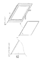
図1に示すように、本実施形態に係るディスプレイ用フィルタ1は、例えばプラズマディスプレイPD(図2)や液晶ディスプレイLD(図3)、その他SEDディスプレイや有機ELディスプレイ等、画像を表示し得る所謂表示装置すなわちディスプレイDに広く採用され得るものである。
Hereinafter, an embodiment of the present invention will be described with reference to the drawings.
<First embodiment>
As shown in FIG. 1, the display filter 1 according to the present embodiment is a so-called so-called plasma display PD (FIG. 2), liquid crystal display LD (FIG. 3), other SED display, organic EL display, or the like. It can be widely used in display devices, that is, displays D.
ここで、本発明に係るディスプレイ用フィルタ1は、発光源から視認部最表面に至る光の経路中に備え付けられることを特徴とする特定波長の光を選択的に吸収する機能を持つディスプレイ用フィルタ1であって、選択的光吸収波長が、570〜605nmの間に存在する色素P及び/又はQを少なくとも有したものとしている。 Here, the display filter 1 according to the present invention is provided in a light path from the light emitting source to the outermost surface of the visual recognition unit, and has a function of selectively absorbing light of a specific wavelength. 1 and the selective light absorption wavelength is at least the dye P and / or Q existing between 570 and 605 nm.
そして、この色素P、Qで表わされるような、テトラアザポルフィリン化合物を含んでいるものであることを特徴とする。 And it is characterized by containing a tetraazaporphyrin compound as represented by these dyes P and Q.
以下、当該色素P及びQについて説明する。 Hereinafter, the dyes P and Q will be described.
P、Qは、式(1)〔化7〕に示すテトラアザポルフィリン化合物に該当するものである。そして、A1、A3、A5及びA7を、ハロゲノアルコキシ基としたものとしているが、A1〜A8における何れか位置にハロゲノアルコキシ基を採用したものとすればよい。 P and Q correspond to the tetraazaporphyrin compound represented by the formula (1) [Chemical Formula 7]. A 1 , A 3 , A 5 and A 7 are halogenoalkoxy groups, but a halogenoalkoxy group may be adopted at any position in A 1 to A 8 .
具体的に説明すると、斯かるハロゲノアルコキシ基を、式(2)〔化8〕で示すものとしている。 More specifically, such a halogenoalkoxy group is represented by the formula (2) [Chemical Formula 8].
ハロゲノアルコキシ基のうち少なくとも何れかが、式(2)で示すものとし、Z1、Z2及びZ3として、フッ素原子を配することにより、トリフルオロアルコキシ基としている。ここで、P及びQともに、A2、A4、A6及びA8の位置に、炭素数1〜20のアルキル基のうち、tert-ブチル基を配したものとしている。 At least one of the halogenoalkoxy groups is represented by the formula (2), and a trifluoroalkoxy group is formed by arranging a fluorine atom as Z 1 , Z 2 and Z 3 . Here, in both P and Q, a tert-butyl group among alkyl groups having 1 to 20 carbon atoms is arranged at the positions of A 2 , A 4 , A 6 and A 8 .
ここで、P、Qは上記一般式(1)におけるMの位置に銅原子並びにオキシバナジウムをそれぞれ配したものとしている。そうすることにより、メチルエチルケトンやトルエンといった一般に広く使用される有機溶媒に対して好適に溶解し得るものとなっている。 Here, P and Q are those in which a copper atom and oxyvanadium are respectively arranged at the position of M in the general formula (1). By doing so, it can be suitably dissolved in commonly used organic solvents such as methyl ethyl ketone and toluene.
そして、上述したような色素P、Qであれば、当該色素P、Qをメチルエチルケトンやトルエンに溶解させて用いることを特徴とする本発明に係るディスプレイ用フィルタ1の製造方法を好適に実現し得るものとなる。 And if it is the pigment | dyes P and Q as mentioned above, the said pigment | dyes P and Q can be suitably implement | achieved, and the manufacturing method of the filter 1 for a display which concerns on this invention characterized by using in methyl ethyl ketone or toluene can be implement | achieved suitably. It will be a thing.
以上のように、本実施形態に係るディスプレイ用フィルタ1は上述した色素P、Qを含むことにより、その製造段階において、例えばメチルエチルケトンやトルエンといった溶媒に対して好適に溶解させることによって高い効率で製造し得るディスプレイ用フィルタ1とすることができる。加えて、常に高強度の光が照射されるディスプレイにおいて耐光性に優れたフィルタを提供することにより、長期間に亘って高品質の画像を表示し得る、言い換えれば耐久性に優れたディスプレイを提供することが可能となる。 As described above, the display filter 1 according to the present embodiment includes the above-described dyes P and Q, and is manufactured with high efficiency by being preferably dissolved in a solvent such as methyl ethyl ketone or toluene in the manufacturing stage. The display filter 1 can be made. In addition, by providing a filter with excellent light resistance in a display that is constantly irradiated with high-intensity light, it is possible to display a high-quality image over a long period of time, in other words, providing a display with excellent durability. It becomes possible to do.
そして、斯かる色素P、Qについて、Z1、Z2、Z3のうちの少なくとも何れか一つを、ハロゲン原子、具体的には、フッ素原子としているものであれば、分子間力が高いというハロゲン原子、特にフッ素原子の特性を反映せしめると考えられ、結果として、より耐光性に優れたものを提供する事が可能となる。 If such dyes P and Q have at least one of Z 1 , Z 2 and Z 3 as a halogen atom, specifically a fluorine atom, the intermolecular force is high. It is considered that the characteristics of halogen atoms, particularly fluorine atoms, are reflected, and as a result, it is possible to provide a more excellent light resistance.
そして、フッ素原子の特性を反映させるための、斯かる色素P、Qのさらに具体的な構成として、A1〜A8の何れかにトリフルオロアルコキシ基を採用したものとしている。 In addition, as a more specific configuration of the dyes P and Q for reflecting the characteristics of the fluorine atom, a trifluoroalkoxy group is adopted for any one of A 1 to A 8 .
そして、式(1)におけるMに該当する具体的なものとして、銅原子又はオキシバナジウムとしたものとすることにより、溶媒に対して、より溶解させ易いものとなっていると考えられる。特に、Mを、銅原子とした色素Pにおいて、トルエンといった一般に扱われる溶媒に対して溶解し易い色素として提供し得ることが可能となる。 And as a concrete thing applicable to M in Formula (1), it is thought that it shall become easier to melt | dissolve with respect to a solvent by setting it as the copper atom or oxyvanadium. In particular, the dye P in which M is a copper atom can be provided as a dye that is easily dissolved in a commonly handled solvent such as toluene.
そして、本発明に係るディスプレイ用フィルタ1、並びにその製造方法によれば、これら色素P、Qを高濃度で溶解させて用い、さらに、色素P、Q自体の優れた耐光性によって、耐久性の高いディスプレイ用フィルタ1を効率的に生産することが可能となる。
<第二実施形態>
次に、上述したプラズマディスプレイ用フィルタ2をプラズマディスプレイPDに好適に適用した態様について、詳述する。なお、本実施形態は、本発明をプラズマディスプレイPDに適用した一例を示したものであり、本発明を何ら限定するものではない。
And according to the display filter 1 and the manufacturing method thereof according to the present invention, these dyes P and Q are used by being dissolved at a high concentration, and further, the excellent light resistance of the dyes P and Q itself makes them durable. It is possible to efficiently produce a high display filter 1.
<Second embodiment>
Next, the aspect which applied suitably the
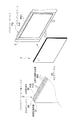
本発明に係るプラズマディスプレイ用フィルタ2は、上記第一実施形態に係るディスプレイ用フィルタ1を、プラズマディスプレイPDに好適に適用したものである。すなわち、本発明に係るプラズマディスプレイPDは、図2に示すように、画像を表示するためのプラズマディスプレイ本体PD1と、プラズマディスプレイPD画面に設けられるプラズマディスプレイ用フィルタ2とを少なくとも具備することを特徴するものである。
The
以下、プラズマディスプレイPD並びにプラズマディスプレイ用フィルタ2の構成の一例を、図面を参照して説明する。
Hereinafter, an example of the configuration of the plasma display PD and the
プラズマディスプレイ用フィルタ2は、図2に示すように、外気側に設けられ、反射防止性及び/又は防眩性を有する機能性透明層21と、プラズマディスプレイPD側に設けられ、画面に接着するための透明粘着層22と、機能性透明層21と透明粘着層22との間に基体として設けられた高分子フィルム23とを少なくとも具備しているものである。そして、これら機能性透明層21、高分子フィルム23および透明粘着層22のうち少なくとも1つの層に、上記実施形態に係る色素P、Qが含まれることを特徴とするものである。言い換えれば、これら機能性透明層21、高分子フィルム23および透明粘着層22のうち少なくとも1つの層が、色素P、Qを含むことにより、上記第一実施形態に係るディスプレイ用フィルタ1を構成しているものである。なお、図示のように、具体的には、色素P、Qを含有可能な厚さ嵩上げ用の高分子フィルム24を、さらに備えたものとしてもよい。
As shown in FIG. 2, the
そして本実施形態では、第一実施形態で説明した色素P、Qの他に、近赤外線吸収色素NRをさらに含んでいるものであるが、その点については後述する。 In this embodiment, in addition to the dyes P and Q described in the first embodiment, a near-infrared absorbing dye NR is further included, which will be described later.
以下、斯かるプラズマディスプレイ用フィルタ2について説明する。
Hereinafter, the
プラズマディスプレイ用フィルタ2は、全体として、30〜85%の可視光線透過率を有するように構成しているものである。
The
機能性透明層21は、上述の通り、外気側に設けられ、反射防止性及び/又は防眩性を有するものである。具体的にはディスプレイへの設置方法や要求される機能に応じて、ハードコート性、反射防止性、防眩性、静電気防止性、防汚性、ガスバリア性、紫外線カット性のいずれか一つ以上の機能を有している。反射防止性を有する機能性透明層21の表面の可視光線反射率は2%以下、好ましくは1.3%以下、さらに好ましくは0.8%以下であることが望ましい。
As described above, the functional
透明粘着層22は、上述の通り、粘着性を有することにより、プラズマディスプレイ本体PD1に対し好適に取り付け得るものである。
As described above, the transparent
高分子フィルム23、或いは嵩上げ用の高分子フィルム24は、上述の通り、機能性透明層21と透明粘着層22との間に基体として設けるものであり、斯かる機能性透明層21と透明粘着層22を好適に支持し得るとともに、透明性を有するものであれば、既存の種々の素材並びに厚みを採用することが可能である。
As described above, the
ここで本実施形態に係るプラズマディスプレイ用フィルタ2は、以下に示す特性を備えているものである。
Here, the
まず、このプラズマディスプレイ用フィルタ2は、赤色発光、更に加えて緑色発光の色純度向上には、波長570nm〜605nmに吸収極大を有する色素P、Qを用いることによって、波長570nm〜605nmにおける電磁波シールド体の最低透過率が、必要な赤色発光のピーク位置での透過率に対して80%以下となるように構成されている。
First, this
具体的には、プラズマディスプレイPDにおいて特に赤色発光がオレンジがかるのは顕著であり、その原因である、本実施形態では、波長580nm〜605nmの発光をディスプレイ用フィルタ1によって低減することによって赤色発光の色純度を向上させることができるようになっている。低減はこの波長領域に吸収波長を有する色素P、Qを含有する色素層を形成することによって行うものとしている。この場合、ディスプレイ用フィルタ1によって、赤色である発光ピークの立つ波長615nm〜640nmの光線透過も著しく損なってしまわないことが必要である。一般に色素はブロードな吸収範囲を有しており、所望の吸収ピークを有していてもその裾の吸収により好適な波長の発光まで吸収するものとなっている。従って、吸収させたい発光の波長に吸収を有する色素でも、その量が多いと好適な発光まで低減してしまい、輝度の著しい低下まで引き起こしてしまう。そこで本実施形態では、波長580nm〜605nmにおける最小透過率を、波長615nm〜640nmにおける最大透過率の10〜85%、好ましくは20〜70%、更に好ましくは20%〜45%であるディスプレイ用フィルタ1とすることにより、赤色発光の色純度を向上させ、その発光輝度を著しく損なわいものとしている。そしてNeによる発光が存在する場合は、そのオレンジ色発光の低減を行うこともできるため、RGB表示セルからの発光の色純度が向上させることができる。 Specifically, it is remarkable that red light emission is particularly orange in the plasma display PD. In this embodiment, which is the cause, red light emission is reduced by reducing the light emission with a wavelength of 580 nm to 605 nm by the display filter 1. Color purity can be improved. The reduction is performed by forming a dye layer containing dyes P and Q having an absorption wavelength in this wavelength region. In this case, it is necessary that the light transmission at a wavelength of 615 nm to 640 nm where the emission peak is red is not significantly impaired by the display filter 1. In general, a dye has a broad absorption range, and even if it has a desired absorption peak, it absorbs light of a suitable wavelength by absorption of the tail. Therefore, even if the amount of the dye having absorption at the wavelength of light emission to be absorbed is large, it is reduced to suitable light emission and causes a significant decrease in luminance. Therefore, in this embodiment, the minimum transmittance at wavelengths of 580 nm to 605 nm is 10 to 85% of the maximum transmittance at wavelengths of 615 nm to 640 nm, preferably 20 to 70%, more preferably 20% to 45%. By setting it to 1, the color purity of red light emission is improved, and the light emission luminance is significantly impaired. When light emission by Ne is present, the orange light emission can be reduced, so that the color purity of light emission from the RGB display cell can be improved.
また、ディスプレイ用フィルタ1を装着したときに発光輝度を著しく損なわないためには、青色、緑色、赤色の発光ピークが存在する波長450n〜480mにおける最大透過率、波長510〜535nmにおける最大透過率、波長615〜640nmにおける最大透過率が、それぞれ45%以上であることが好ましい。これら波長範囲におけるディスプレイ用フィルタ1の最大透過率は、各構成部材により85%以下となる。 Further, in order not to significantly impair the emission luminance when the display filter 1 is mounted, the maximum transmittance at wavelengths of 450 n to 480 m where blue, green, and red emission peaks exist, the maximum transmittance at wavelengths of 510 to 535 nm, The maximum transmittance at a wavelength of 615 to 640 nm is preferably 45% or more. The maximum transmittance of the display filter 1 in these wavelength ranges is 85% or less depending on each component.
さらにまた、赤色発光の色純度向上と同様に、緑色発光の色純度向上には、波長510〜535nm程度の緑色の長波長側に隣接する黄緑〜緑黄〜黄色である波長540nm〜580nmをある程度低減すれば良い。ディスプレイ用フィルタ1の波長540〜580nmにおける最小透過率が波長510〜535nmにおける最大透過率の10〜90%、好ましくは20〜50%であることが好適である。これにより、緑色が黄色を帯びるのを防ぎ、その色純度を向上させているのである。 Furthermore, as with the improvement of the color purity of the red light emission, the improvement of the color purity of the green light emission is achieved by changing the wavelength of 540 nm to 580 nm, which is adjacent to the long wavelength side of the green having a wavelength of about 510 to 535 nm. What is necessary is just to reduce to some extent. The minimum transmittance of the display filter 1 at a wavelength of 540 to 580 nm is 10 to 90%, preferably 20 to 50% of the maximum transmittance at a wavelength of 510 to 535 nm. This prevents the green from becoming yellowish and improves its color purity.
さらにまた同様に、青色発光の色純度向上と緑色発光の色純度向上には、それぞれの好適な発光波長の間にある波長480nm〜510nmでの不要発光を低減すれば良く、その波長範囲におけるディスプレイ用フィルタ1の最小透過率が波長450〜480nmにおける最大透過率及び/又は波長510〜535nmにおける最大透過率の50〜90%、好ましくは50〜75%であることが好適である。これにより、青色が緑色がかること及び/又は緑色が青色がかることを防ぎ、その色純度を向上させることができるのである。色純度の向上はコントラストを向上させ得るものとなっている。 Furthermore, similarly, in order to improve the color purity of blue light emission and the color purity of green light emission, it is only necessary to reduce unnecessary light emission at wavelengths of 480 nm to 510 nm between the respective suitable light emission wavelengths. It is preferable that the minimum transmittance of the filter 1 for use is 50 to 90%, preferably 50 to 75% of the maximum transmittance at a wavelength of 450 to 480 nm and / or the maximum transmittance at a wavelength of 510 to 535 nm. Thereby, it can prevent that blue becomes green and / or green becomes blue, and can improve the color purity. The improvement in color purity can improve the contrast.
また、プラズマディスプレイPDの緑色発光のピークは、例えばNTSC方式で要求される緑色より若干長波長側すなわち黄緑側にあることがあり、その黄色味を無くすように発光ピークの長波長側を削り、短波長側にピークを有するようにすることも、緑色発光の色純度を向上させるのに有効である。すなわち、520〜540nmにおいて、波長が長くなると透過率が単調減少するようにすれば良い。 In addition, the green light emission peak of the plasma display PD may be slightly longer than the green color required by the NTSC system, for example, on the yellowish green side, and the long wavelength side of the light emission peak is trimmed to eliminate the yellowishness. It is also effective to improve the color purity of green light emission to have a peak on the short wavelength side. That is, at 520 to 540 nm, the transmittance may monotonously decrease as the wavelength increases.
さらに上述の通り、プラズマディスプレイPDからでる800〜1000nm付近の近赤外線線を効率よくカットするための、近赤外線吸収色素NRをさらに含んでいる。そのため、波長800〜1100nmにおける透過率極小が20%以下という特性を示している。そのため、周辺電子機器のリモコン、伝送系光通信等が使用する波長に悪影響を与えず、それらの誤動作を防ぐことができる。 Further, as described above, it further includes a near-infrared absorbing dye NR for efficiently cutting near-infrared rays in the vicinity of 800 to 1000 nm emitted from the plasma display PD. For this reason, the transmittance minimum at a wavelength of 800 to 1100 nm is 20% or less. For this reason, it is possible to prevent malfunctions of the peripheral electronic devices without adversely affecting the wavelengths used by the remote control, transmission optical communication, and the like.
加えて、電磁波シールド体が含有する色素が、ディスプレイから放射される、又は、外光が含む紫外線により劣化することを防ぐために、機能性透明層21が、紫外線カット性を有していると良い。例えば、紫外線を吸収する無機薄膜単層又は多層からなる反射防止膜、又は、紫外線吸収剤を含有する機能性透明膜を形成する基材、ハードコート膜を有している機能性透明層21である。紫外線吸収剤の種類、濃度は特に限定されない。
また、透明粘着層22のうち少なくとも1つの層は紫外線吸収剤を含有していても良い。
紫外線カットする部材は、紫外線が入射する面と色素を含有する層の間に配されることが肝要であり、紫外線カット性は、色素の耐久性によって異なり特に限定されない。
<第三実施形態>
続いて、第一実施形態に示したディスプレイ用フィルタ1を、液晶ディスプレイLDに好適に適用した態様について、詳述する。
In addition, in order to prevent the pigment contained in the electromagnetic wave shielding body from being emitted from the display or being deteriorated by the ultraviolet rays included in the external light, the functional
Further, at least one layer of the transparent
It is important that the UV-cutting member is disposed between the surface on which the UV light is incident and the layer containing the dye, and the UV-cutting property varies depending on the durability of the dye and is not particularly limited.
<Third embodiment>
Next, a mode in which the display filter 1 shown in the first embodiment is suitably applied to the liquid crystal display LD will be described in detail.
画面を表示し得る液晶ディスプレイ本体LD1に、上記第一実施形態に係るディスプレイ用フィルタ1を適用することにより、本発明に係る液晶ディスプレイLDを構成しているものである。 The liquid crystal display LD according to the present invention is configured by applying the display filter 1 according to the first embodiment to the liquid crystal display main body LD1 capable of displaying a screen.
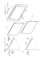
ここで、本実施形態に係る液晶ディスプレイ用フィルタ3は、透明性を有する板状の高分子成形体31或いはガラス板31gに、透明粘着層32を重層させることにより、液晶ディスプレイLD内の特定の位置に好適に配置し得るものとしている。そして、高分子成形体31内或いは透明粘着層32に、第一実施形態に示した色素P、Qを含ませることにより、液晶ディスプレイ用フィルタ3を好適に構成しているものである。
Here, the liquid
また本実施形態に斯かる液晶ディスプレイ用フィルタ3は、ガラス板31g又は高分子成形体31の表面にコート層を設け、当該コート層に色素P、Qを含んだものであってもよい。また後述の通り、液晶ディスプレイLDを構成する構成要素に色素P、Qを含ませたものであっても良い。
Further, the liquid
高分子成形体31は、透明性を有し、色素P、Qが、高分子成形体31内に含有されたものとなっている。そして、当該高分子成形体31を構成する素材としては種々のものを挙げることができるが、品質、加工特性といった観点から、ポリエチレンテレフタレート又はトリアセチルセルロース又はポリカーボネートとすることが望ましい。
The polymer molded
透明粘着層32は、透明性を担保しつつ、液晶ディスプレイ本体LD1に好適に貼付し得るものである。具体的には、当該透明粘着層32は、アクリル系樹脂又はシリコン系樹脂を主成分とするアクリル系粘着剤又はシリコン系粘着剤を主体とし、これら粘着剤に色素P、Qを含ませたものとすることが望ましい。
The transparent
ここで透明性があるとは、実用上の厚さにおける、波長400〜700(nm)の光線透過率が40%以上であることをいう。そして、色素P、Qに係る選択的光吸収波長における透過率が、1〜50%であるという特性を示している。 Here, being transparent means that the light transmittance at a wavelength of 400 to 700 (nm) at a practical thickness is 40% or more. And the transmittance | permeability in the selective light absorption wavelength which concerns on the pigment | dyes P and Q has shown the characteristic that it is 1 to 50%.
ここで、上述した液晶ディスプレイ用フィルタ3を液晶ディスプレイ本体LD1に用いる具体的な態様について説明する。
Here, the specific aspect which uses the
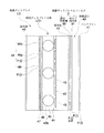
液晶ディスプレイ本体LD1は、図4、図5及び図6に模式的な断面として示すように、バックライト41から順に、導光板としての偏光板42、配向膜43、配向膜43に設けられた透明電極44、液晶45、液晶45を配置する領域を確保するスペーサとしてのビーズ45b、配向膜46、透明電極47、三色のカラーフィルタ48(48b、48g、48r)、偏光板49の順に配置されている。
The liquid crystal display main body LD1 is a transparent film provided on a
そして本実施形態に係る液晶ディスプレイ用フィルタ3は、導光板表面上のバックライトからの光を取り入れる側面部分40に粘着粘着剤を介して貼付けることによって用いられる。具体的には、図4に示すように、バックライト41表面に粘着剤を介して貼付けることにより用いられるか、或いは、図5に示すように、偏光板42に貼りつけることにより用いられることが望ましい。この場合、液晶ディスプレイ用フィルタ3を貼付ける為の粘着剤は、透明粘着層32である場合も、色素P、Qを含まない他の粘着剤である場合も含むものである。また図6に示すように、液晶ディスプレイ本体LD1の表面側に設けられた偏光板49に貼付けたものであってもよい。
And the
また、本実施形態にあっても、上述の通り、800〜1000nm付近の近赤外線を効率よくカットするための、第二実施形態で示した近赤外線吸収色素NR等、選択的光吸収機能を有する他の色素をさらに含んでいるものとしてもよい。 Further, even in the present embodiment, as described above, it has a selective light absorbing function such as the near infrared absorbing dye NR shown in the second embodiment for efficiently cutting near infrared light in the vicinity of 800 to 1000 nm. Other pigments may be further included.
また、上記の態様以外にも、カラーフィルタに対して色素P、Qを含有させる事により、本発明における光学フィルタとしたものであっても良い。その場合、緑及び赤色発色部分に色素P、Qを含有させれば良い。通常は、用いる顔料に予め色素P、Qを含有させておくことが望ましい。 In addition to the above-described aspects, the optical filter according to the present invention may be obtained by adding the dyes P and Q to the color filter. In that case, the dyes P and Q may be contained in the green and red coloring portions. Usually, it is desirable that the pigments to be used contain the dyes P and Q in advance.
以上、本発明の各実施形態について説明したが、各部の具体的な構成は、上述した実施形態のみに限定されるものではなく、本発明の趣旨を逸脱しない範囲で種々変形が可能である。例えば、色素P、Qを含ませる箇所は一箇所に限られることはなく、プラズマディスプレイPD或いは液晶ディスプレイLD内の複数の箇所に含ませたものであってもよい。 Although the embodiments of the present invention have been described above, the specific configuration of each unit is not limited to the above-described embodiments, and various modifications can be made without departing from the spirit of the present invention. For example, the location where the dyes P and Q are included is not limited to one location, and may be included in a plurality of locations in the plasma display PD or the liquid crystal display LD.
その他、各部の具体的構成についても上記実施形態に限られるものではなく、本発明の趣旨を逸脱しない範囲で種々変形が可能である。 In addition, the specific configuration of each part is not limited to the above embodiment, and various modifications can be made without departing from the spirit of the present invention.
以下に本発明の実施例について詳述するが、本発明は当該実施例に何ら限定されるものではない。
1.溶解性試験
<供試材料>
実施例1
上記実施形態における色素P、すなわち、下記〔化9〕に示すテトラアザポルフィリン化合物を供試した。
Examples of the present invention will be described in detail below, but the present invention is not limited to the examples.
1. Solubility test <test material>
Example 1
The dye P in the above embodiment, that is, the tetraazaporphyrin compound represented by the following [Chemical 9] was used.
実施例2
上記実施形態における色素Q、すなわち、下記〔化10〕に示すテトラアザポルフィリン化合物を供試した。
Example 2
The dye Q in the above embodiment, that is, the tetraazaporphyrin compound shown in the following [Chemical Formula 10] was used.
比較例1
三井化学社製PD―319、すなわち、下記〔化11〕に示すテトラアザポルフィリン化合物を供試した。
Comparative Example 1
PD-319 manufactured by Mitsui Chemicals, that is, a tetraazaporphyrin compound represented by the following [Chemical Formula 11] was used.
比較例2
三井化学社製PD―311、すなわち、下記〔化12〕に示すテトラアザポルフィリン化合物を供試した。
Comparative Example 2
PD-311 manufactured by Mitsui Chemicals, that is, a tetraazaporphyrin compound represented by the following [Chemical Formula 12] was used.
比較例3
下記〔化13〕に示すテトラアザポルフィリン化合物を供試した。
Comparative Example 3
A tetraazaporphyrin compound represented by the following [Chemical Formula 13] was tested.
<試験方法>
上記実施例1、実施例2、比較例1、比較例2及び比較例3を供試し、それぞれエチルメチルケトン並びにトルエンに対する溶解性(W/V)を測定した。
<試験結果>
試験結果を表1に示す
<Test method>
The said Example 1, Example 2, the comparative example 1, the comparative example 2, and the comparative example 3 were tested, and the solubility (W / V) with respect to ethyl methyl ketone and toluene was measured, respectively.
<Test results>
The test results are shown in Table 1.
表1により明らかなように、実施例1並びに実施例2に係る色素は、溶媒であるメチルエチルケトン並びにトルエンに対して実用上十分な溶解性を示したため、これら溶媒に溶解させて好適にディスプレイ用フィルタ1を製造し得ることが判明した。このことは、各実施例並びに各比較例において錯体を構成するための金属原子の種類も結果に影響しているものと思われる。しかしながら、同じ銅錯体である実施例1と比較例1並びに比較例3とでメチルエチルケトンに対する溶解性が大きく異なっている。このことから、各実施例に係る色素がハロゲノアルコキシ基、詳細にはトリフルオロアルコキシ基を有している点が、有機溶媒に対する溶解性を大きく向上させているものと考えられる。
2.耐光性試験
<供試材料>
上記溶解性試験に係る実施例1、実施例2、比較例1、比較例2及び比較例3に係る各色素を供試した。
<試験方法>
ポリメタクリレート75.0g、クロロベンゼン152.6g、トルエン59.6g、酢酸エチル62.5g及びアセトン55.0gを混合し、十分に撹拌してポリマー溶液を調整した。このポリマー溶液5.4gを採取して、ここに実施例1に係る色素6mg加えて色素のポリマー溶液を調整した。そして色素のポリマー溶液450μlを採取して、これを5cm×20cmのポリプロピレンシート上にロッドコーター法により塗布した。90℃で3分間乾燥後、室温で一晩熟成させて耐光性試験に供する色素の薄膜フィルムを得た。また、実施例2、比較例1、比較例2及び比較例3に係る各色素の薄膜フィルムも同様にして得た。このようにして得られた各色素の薄膜フィルムを2万ルクスの蛍光灯に88時間暴露させて、各色素の薄膜フィルムの透過率を測定した。これらの測定値と暴露前に測定した透過率から各色素の保存率を算出した。
<試験結果>
試験結果を表1に示す
As is clear from Table 1, the dyes according to Example 1 and Example 2 showed practically sufficient solubility in methyl ethyl ketone and toluene as solvents, so that they can be dissolved in these solvents and suitably used for display filters. It has been found that 1 can be produced. This is considered to be due to the influence of the kind of metal atom for constituting the complex in each example and each comparative example. However, Example 1 which is the same copper complex, and Comparative Example 1 and Comparative Example 3 have greatly different solubility in methyl ethyl ketone. From this, it is considered that the dyes according to each Example have a halogenoalkoxy group, specifically, a trifluoroalkoxy group, which greatly improves the solubility in organic solvents.
2. Light resistance test <Test material>
Each dye according to Example 1, Example 2, Comparative Example 1, Comparative Example 2, and Comparative Example 3 related to the solubility test was used.
<Test method>
75.0 g of polymethacrylate, 152.6 g of chlorobenzene, 59.6 g of toluene, 62.5 g of ethyl acetate and 55.0 g of acetone were mixed and sufficiently stirred to prepare a polymer solution. 5.4 g of this polymer solution was sampled, and 6 mg of the dye according to Example 1 was added thereto to prepare a dye polymer solution. Then, 450 μl of a dye polymer solution was collected and applied onto a 5 cm × 20 cm polypropylene sheet by a rod coater method. After drying at 90 ° C. for 3 minutes, the film was aged at room temperature overnight to obtain a thin film of a dye for use in the light resistance test. Moreover, the thin film film of each pigment | dye which concerns on Example 2, the comparative example 1, the comparative example 2, and the comparative example 3 was obtained similarly. The thus obtained thin film of each dye was exposed to a fluorescent lamp of 20,000 lux for 88 hours, and the transmittance of the thin film of each dye was measured. The storage rate of each pigment was calculated from these measured values and the transmittance measured before exposure.
<Test results>
The test results are shown in Table 1.
表2より明らかなように、実施例1及び実施例2が比較例1、比較例2及び比較例3に対して、より耐光性が高いことが示された。このことから、実施例1及び実施例2をディスプレイ用フィルタ1に採用した場合、ディスプレイの耐久性の向上に十分寄与するものと考えることができる。このことは、実施例1及び実施例2に係る色素は、構造上、ハロゲノアルコキシ基、詳細にはトリフルオロアルコキシ基を有するものであるため、比較例1、比較例2及び比較例3に係る色素よりも、高い耐光性を示しているものと考えられる。 As is clear from Table 2, Example 1 and Example 2 showed higher light resistance than Comparative Example 1, Comparative Example 2 and Comparative Example 3. From this, when Example 1 and Example 2 are employ | adopted for the filter 1 for a display, it can be considered that it contributes enough to the improvement of the durability of a display. This is because the dyes according to Example 1 and Example 2 structurally have a halogenoalkoxy group, specifically, a trifluoroalkoxy group, and therefore, according to Comparative Example 1, Comparative Example 2, and Comparative Example 3. It is considered that the light resistance is higher than that of the dye.
以上のように、本実施例において示した実施例1及び実施例2は、溶解性が優れているため、本発明に係るディスプレイ用フィルタを好適に製造し得るものである。加えて、耐光性が各比較例に比べて優れたものとなっているため、耐久性に優れたディスプレイ用フィルタの製造に有効に寄与し得るものとなると考えられる。 As described above, Example 1 and Example 2 shown in this example are excellent in solubility, so that the display filter according to the present invention can be suitably manufactured. In addition, since the light resistance is superior to each comparative example, it is considered that the light resistance can be effectively contributed to the manufacture of a display filter having excellent durability.
1…ディスプレイ用フィルタ
2…プラズマディスプレイ用フィルタ
3…液晶ディスプレイ用フィルタ、
21…機能性透明層
22、32…透明粘着層
23、24…高分子フィルム
31…高分子成形体
31g…ガラス板
40…光を取り入れる側面部分(側面部分)
41…バックライト
42、49…偏光板
D…ディスプレイ
PD…プラズマディスプレイ
LD…液晶ディスプレイ
PD1…プラズマディスプレイ本体
P、Q…色素
NR…近赤外線吸収色素
DESCRIPTION OF SYMBOLS 1 ...
DESCRIPTION OF
41 ...
Claims (35)
選択的光吸収波長が、570〜605nmの間に存在する色素を少なくとも有し、当該色素が、式(1)〔化1〕で表わされるテトラアザポルフィリン化合物であることを特徴とするディスプレイ用フィルタ。
A filter for display having at least a dye having a selective light absorption wavelength of 570 to 605 nm, and the dye is a tetraazaporphyrin compound represented by the formula (1) [Chemical Formula 1] .
前記色素をメチルエチルケトンに溶解させて用いることを特徴とするディスプレイ用フィルタの製造方法。 A method for manufacturing a display filter according to any one of claims 1 to 8,
A method for producing a display filter, wherein the dye is dissolved in methyl ethyl ketone.
前記色素をトルエンに溶解させて用いることを特徴とするディスプレイ用フィルタの製造方法。 A method for manufacturing a display filter according to any one of claims 1 to 8,
A method for producing a display filter, wherein the dye is dissolved in toluene.
外気側に設けられ、反射防止性及び/又は防眩性を有する機能性透明層と、
プラズマディスプレイ側に設けられ、画面に接着するための透明粘着層と、
機能性透明層と透明粘着層との間に基体として設けられた高分子フィルムとを備え、
機能性透明層、高分子フィルムおよび透明粘着層のうち少なくとも1つの層に、前記色素が含まれることを特徴とするプラズマディスプレイ用フィルタ。 The display filter according to any one of claims 1 to 7 is used for a plasma display main body capable of displaying an image,
A functional transparent layer provided on the outside air side and having antireflection and / or antiglare properties;
A transparent adhesive layer provided on the plasma display side for bonding to the screen;
A polymer film provided as a substrate between the functional transparent layer and the transparent adhesive layer;
A filter for plasma display, wherein the dye is contained in at least one of a functional transparent layer, a polymer film, and a transparent adhesive layer.
プラズマディスプレイ画面に設けられ、請求項11乃至22の何れかに記載のプラズマディスプレイ用フィルタとを少なくとも具備することを特徴するプラズマディスプレイ。 A plasma display body for displaying images;
23. A plasma display comprising at least a filter for plasma display according to any one of claims 11 to 22 provided on a plasma display screen.
前記色素が、透明粘着層に含有されていることを特徴とする請求項24又は25に記載の液晶ディスプレイ用フィルタ。 At least a polymer molded body or a glass plate, and a transparent adhesive layer laminated on the polymer molded body or the glass plate,
The liquid crystal display filter according to claim 24 or 25, wherein the pigment is contained in a transparent adhesive layer.
前記色素が、前記高分子成形体内に含有されていることを特徴とする請求項23、24、26又は27記載の液晶ディスプレイ用フィルタ。 Having at least a polymer molded body,
The liquid crystal display filter according to claim 23, 24, 26 or 27, wherein the dye is contained in the polymer molded body.
Priority Applications (1)
| Application Number | Priority Date | Filing Date | Title |
|---|---|---|---|
| JP2007107863A JP2008268331A (en) | 2007-04-17 | 2007-04-17 | Filter for display, manufacturing method thereof, filter for plasma display, plasma display, filter for liquid crystal display, and liquid crystal display |
Applications Claiming Priority (1)
| Application Number | Priority Date | Filing Date | Title |
|---|---|---|---|
| JP2007107863A JP2008268331A (en) | 2007-04-17 | 2007-04-17 | Filter for display, manufacturing method thereof, filter for plasma display, plasma display, filter for liquid crystal display, and liquid crystal display |
Publications (1)
| Publication Number | Publication Date |
|---|---|
| JP2008268331A true JP2008268331A (en) | 2008-11-06 |
Family
ID=40047959
Family Applications (1)
| Application Number | Title | Priority Date | Filing Date |
|---|---|---|---|
| JP2007107863A Pending JP2008268331A (en) | 2007-04-17 | 2007-04-17 | Filter for display, manufacturing method thereof, filter for plasma display, plasma display, filter for liquid crystal display, and liquid crystal display |
Country Status (1)
| Country | Link |
|---|---|
| JP (1) | JP2008268331A (en) |
Cited By (5)
| Publication number | Priority date | Publication date | Assignee | Title |
|---|---|---|---|---|
| JP2011116818A (en) * | 2009-12-01 | 2011-06-16 | Yamamoto Chem Inc | Tetraazaporphyrin compound and display filter |
| JP2011221456A (en) * | 2010-04-14 | 2011-11-04 | Yamamoto Chem Inc | Color correction filter and tetraaza porphyrin compound used in color correction filter |
| CN103052904A (en) * | 2010-08-12 | 2013-04-17 | 三井化学株式会社 | Plastic polarizing lens, method for producing same, and polarizing film |
| WO2013146322A1 (en) * | 2012-03-30 | 2013-10-03 | 富士フイルム株式会社 | Colored curable composition, color filter and method for producing color filter, and display device |
| WO2014155787A1 (en) * | 2013-03-29 | 2014-10-02 | 積水化成品工業株式会社 | Optical film |
Citations (6)
| Publication number | Priority date | Publication date | Assignee | Title |
|---|---|---|---|---|
| JP2000275432A (en) * | 1999-01-22 | 2000-10-06 | Mitsui Chemicals Inc | Display filter |
| JP2002040233A (en) * | 2000-07-21 | 2002-02-06 | Mitsui Chemicals Inc | Optical filter |
| JP2002251144A (en) * | 2000-02-01 | 2002-09-06 | Mitsui Chemicals Inc | Filter for display, display device and method for manufacturing the same |
| JP2004361551A (en) * | 2003-06-03 | 2004-12-24 | Mitsui Chemicals Inc | Optical filter |
| JP2007528504A (en) * | 2004-02-23 | 2007-10-11 | エルジー・ケム・リミテッド | Adhesive film and plasma display panel filter having color correction and near infrared absorption function |
| WO2008105235A1 (en) * | 2007-02-26 | 2008-09-04 | Konica Minolta Holdings, Inc. | Composition, optical filter, and front-side filter for display |
-
2007
- 2007-04-17 JP JP2007107863A patent/JP2008268331A/en active Pending
Patent Citations (6)
| Publication number | Priority date | Publication date | Assignee | Title |
|---|---|---|---|---|
| JP2000275432A (en) * | 1999-01-22 | 2000-10-06 | Mitsui Chemicals Inc | Display filter |
| JP2002251144A (en) * | 2000-02-01 | 2002-09-06 | Mitsui Chemicals Inc | Filter for display, display device and method for manufacturing the same |
| JP2002040233A (en) * | 2000-07-21 | 2002-02-06 | Mitsui Chemicals Inc | Optical filter |
| JP2004361551A (en) * | 2003-06-03 | 2004-12-24 | Mitsui Chemicals Inc | Optical filter |
| JP2007528504A (en) * | 2004-02-23 | 2007-10-11 | エルジー・ケム・リミテッド | Adhesive film and plasma display panel filter having color correction and near infrared absorption function |
| WO2008105235A1 (en) * | 2007-02-26 | 2008-09-04 | Konica Minolta Holdings, Inc. | Composition, optical filter, and front-side filter for display |
Cited By (8)
| Publication number | Priority date | Publication date | Assignee | Title |
|---|---|---|---|---|
| JP2011116818A (en) * | 2009-12-01 | 2011-06-16 | Yamamoto Chem Inc | Tetraazaporphyrin compound and display filter |
| JP2011221456A (en) * | 2010-04-14 | 2011-11-04 | Yamamoto Chem Inc | Color correction filter and tetraaza porphyrin compound used in color correction filter |
| CN103052904A (en) * | 2010-08-12 | 2013-04-17 | 三井化学株式会社 | Plastic polarizing lens, method for producing same, and polarizing film |
| US9086531B2 (en) | 2010-08-12 | 2015-07-21 | Mitsui Chemicals, Inc. | Plastic polarized lens, method for producing the same, and polarized film |
| CN103052904B (en) * | 2010-08-12 | 2016-01-06 | 三井化学株式会社 | Plastic polarizing lens, its manufacture method and light polarizing film |
| WO2013146322A1 (en) * | 2012-03-30 | 2013-10-03 | 富士フイルム株式会社 | Colored curable composition, color filter and method for producing color filter, and display device |
| WO2014155787A1 (en) * | 2013-03-29 | 2014-10-02 | 積水化成品工業株式会社 | Optical film |
| JP6069490B2 (en) * | 2013-03-29 | 2017-02-01 | 積水化成品工業株式会社 | Optical film |
Similar Documents
| Publication | Publication Date | Title |
|---|---|---|
| JP5428223B2 (en) | Metal complex dye and filter for display | |
| US20070293666A1 (en) | Optical Filter and Its Applications, and Porphyrin Compound Used in Optical Filter | |
| JP4086871B2 (en) | Near-infrared shield and display front plate | |
| CA2838581A1 (en) | Optical filter, solid-state imaging element, imaging device lens and imaging device | |
| JP4617029B2 (en) | Optical filter | |
| JP3721298B2 (en) | Phthalocyanine compound, method for producing the same, and near infrared absorbing dye using the same | |
| JP2008050599A (en) | Phthalocyanine compound | |
| TWI535794B (en) | Phthalocyanine compounds, near infrared absorption pigments and near infrared absorbers | |
| JP2008268331A (en) | Filter for display, manufacturing method thereof, filter for plasma display, plasma display, filter for liquid crystal display, and liquid crystal display | |
| JP2008216589A (en) | OPTICAL LAYER INCLUDING mu-OXO-BRIDGED BORON SUBPHTHALOCYANINE DIMER | |
| JP5010123B2 (en) | Phthalocyanine compound and near-infrared absorbing dye comprising the same | |
| JP2006313303A (en) | Optical filter and display using the same | |
| JP5484841B2 (en) | Phthalocyanine compounds | |
| JP2002040233A (en) | Optical filter | |
| JP2011093958A (en) | Near-infrared ray absorbing adhesive composition and near infrared ray absorbing adhesive layer | |
| JP5289813B2 (en) | Phthalocyanine compounds | |
| JP2004309655A (en) | Near infrared absorbing filter, and plasma display front board, and plasma display using filter | |
| JP4485778B2 (en) | Tetraazaporphyrin dye and optical filter using the same | |
| JP2006189751A (en) | Optical filter for display | |
| JPWO2008050725A1 (en) | Near-infrared absorbing dye composition and near-infrared absorbing filter and adhesive containing the same | |
| JP4499960B2 (en) | Optical filter | |
| JP4544914B2 (en) | Dye for plasma display front panel and plasma display front panel using the same | |
| JP5606492B2 (en) | Phthalocyanine compounds | |
| JP3932761B2 (en) | Organometallic complex, infrared absorption filter using the same and filter for plasma display panel | |
| JP5539676B2 (en) | Phthalocyanine compounds |
Legal Events
| Date | Code | Title | Description |
|---|---|---|---|
| A621 | Written request for application examination |
Free format text: JAPANESE INTERMEDIATE CODE: A621 Effective date: 20100319 |
|
| A131 | Notification of reasons for refusal |
Free format text: JAPANESE INTERMEDIATE CODE: A131 Effective date: 20121225 |
|
| A02 | Decision of refusal |
Free format text: JAPANESE INTERMEDIATE CODE: A02 Effective date: 20130507 |