JP4086871B2 - Near-infrared shield and display front plate - Google Patents
Near-infrared shield and display front plate Download PDFInfo
- Publication number
- JP4086871B2 JP4086871B2 JP2005292688A JP2005292688A JP4086871B2 JP 4086871 B2 JP4086871 B2 JP 4086871B2 JP 2005292688 A JP2005292688 A JP 2005292688A JP 2005292688 A JP2005292688 A JP 2005292688A JP 4086871 B2 JP4086871 B2 JP 4086871B2
- Authority
- JP
- Japan
- Prior art keywords
- infrared
- compound
- layer
- shield
- refractive index
- Prior art date
- Legal status (The legal status is an assumption and is not a legal conclusion. Google has not performed a legal analysis and makes no representation as to the accuracy of the status listed.)
- Expired - Fee Related
Links
- -1 sulfonic acid imide Chemical class 0.000 claims description 71
- 150000001875 compounds Chemical class 0.000 claims description 69
- 238000010521 absorption reaction Methods 0.000 claims description 41
- 239000000463 material Substances 0.000 claims description 41
- 229920005989 resin Polymers 0.000 claims description 31
- 239000011347 resin Substances 0.000 claims description 31
- 239000000758 substrate Substances 0.000 claims description 25
- 150000002500 ions Chemical class 0.000 claims description 17
- 125000000217 alkyl group Chemical group 0.000 claims description 16
- 125000000623 heterocyclic group Chemical group 0.000 claims description 16
- QJGQUHMNIGDVPM-UHFFFAOYSA-N nitrogen group Chemical group [N] QJGQUHMNIGDVPM-UHFFFAOYSA-N 0.000 claims description 16
- 229910052757 nitrogen Inorganic materials 0.000 claims description 14
- 125000004432 carbon atom Chemical group C* 0.000 claims description 12
- 150000001768 cations Chemical class 0.000 claims description 12
- 150000001450 anions Chemical class 0.000 claims description 9
- 125000004573 morpholin-4-yl group Chemical group N1(CCOCC1)* 0.000 claims description 8
- 125000001424 substituent group Chemical group 0.000 claims description 8
- 230000014509 gene expression Effects 0.000 claims description 5
- 125000001997 phenyl group Chemical class [H]C1=C([H])C([H])=C(*)C([H])=C1[H] 0.000 claims description 5
- 125000003282 alkyl amino group Chemical group 0.000 claims description 4
- 150000002391 heterocyclic compounds Chemical class 0.000 claims description 4
- 125000004433 nitrogen atom Chemical group N* 0.000 claims description 4
- 125000000446 sulfanediyl group Chemical group *S* 0.000 claims description 4
- 229910052723 transition metal Inorganic materials 0.000 claims description 4
- 150000003624 transition metals Chemical class 0.000 claims description 4
- 230000009477 glass transition Effects 0.000 claims description 3
- UHOVQNZJYSORNB-UHFFFAOYSA-N monobenzene Natural products C1=CC=CC=C1 UHOVQNZJYSORNB-UHFFFAOYSA-N 0.000 claims 2
- 239000010410 layer Substances 0.000 description 132
- 230000003595 spectral effect Effects 0.000 description 48
- 238000002834 transmittance Methods 0.000 description 48
- 238000000576 coating method Methods 0.000 description 21
- 238000012360 testing method Methods 0.000 description 21
- 239000011248 coating agent Substances 0.000 description 18
- 239000010419 fine particle Substances 0.000 description 18
- 230000008859 change Effects 0.000 description 16
- 229920002799 BoPET Polymers 0.000 description 12
- VYPSYNLAJGMNEJ-UHFFFAOYSA-N Silicium dioxide Chemical compound O=[Si]=O VYPSYNLAJGMNEJ-UHFFFAOYSA-N 0.000 description 11
- 230000006870 function Effects 0.000 description 11
- 239000011342 resin composition Substances 0.000 description 11
- GWEVSGVZZGPLCZ-UHFFFAOYSA-N Titan oxide Chemical compound O=[Ti]=O GWEVSGVZZGPLCZ-UHFFFAOYSA-N 0.000 description 10
- 238000000034 method Methods 0.000 description 10
- ZMXDDKWLCZADIW-UHFFFAOYSA-N N,N-Dimethylformamide Chemical compound CN(C)C=O ZMXDDKWLCZADIW-UHFFFAOYSA-N 0.000 description 9
- 239000011521 glass Substances 0.000 description 9
- 230000003287 optical effect Effects 0.000 description 9
- OGIDPMRJRNCKJF-UHFFFAOYSA-N titanium oxide Inorganic materials [Ti]=O OGIDPMRJRNCKJF-UHFFFAOYSA-N 0.000 description 9
- 230000005540 biological transmission Effects 0.000 description 7
- 230000000052 comparative effect Effects 0.000 description 7
- ZWEHNKRNPOVVGH-UHFFFAOYSA-N 2-Butanone Chemical compound CCC(C)=O ZWEHNKRNPOVVGH-UHFFFAOYSA-N 0.000 description 6
- YXFVVABEGXRONW-UHFFFAOYSA-N Toluene Chemical compound CC1=CC=CC=C1 YXFVVABEGXRONW-UHFFFAOYSA-N 0.000 description 6
- 239000002131 composite material Substances 0.000 description 6
- 238000005520 cutting process Methods 0.000 description 6
- 238000002156 mixing Methods 0.000 description 6
- 229910052754 neon Inorganic materials 0.000 description 6
- GKAOGPIIYCISHV-UHFFFAOYSA-N neon atom Chemical compound [Ne] GKAOGPIIYCISHV-UHFFFAOYSA-N 0.000 description 6
- IEQIEDJGQAUEQZ-UHFFFAOYSA-N phthalocyanine Chemical class N1C(N=C2C3=CC=CC=C3C(N=C3C4=CC=CC=C4C(=N4)N3)=N2)=C(C=CC=C2)C2=C1N=C1C2=CC=CC=C2C4=N1 IEQIEDJGQAUEQZ-UHFFFAOYSA-N 0.000 description 6
- 229910052724 xenon Inorganic materials 0.000 description 6
- FHNFHKCVQCLJFQ-UHFFFAOYSA-N xenon atom Chemical compound [Xe] FHNFHKCVQCLJFQ-UHFFFAOYSA-N 0.000 description 6
- 239000002253 acid Substances 0.000 description 5
- 239000007788 liquid Substances 0.000 description 5
- 230000007774 longterm Effects 0.000 description 5
- 239000000377 silicon dioxide Substances 0.000 description 5
- 239000000243 solution Substances 0.000 description 5
- 239000002904 solvent Substances 0.000 description 5
- 238000003860 storage Methods 0.000 description 5
- 229920001187 thermosetting polymer Polymers 0.000 description 5
- NTIZESTWPVYFNL-UHFFFAOYSA-N Methyl isobutyl ketone Chemical compound CC(C)CC(C)=O NTIZESTWPVYFNL-UHFFFAOYSA-N 0.000 description 4
- UIHCLUNTQKBZGK-UHFFFAOYSA-N Methyl isobutyl ketone Natural products CCC(C)C(C)=O UIHCLUNTQKBZGK-UHFFFAOYSA-N 0.000 description 4
- XLOMVQKBTHCTTD-UHFFFAOYSA-N Zinc monoxide Chemical compound [Zn]=O XLOMVQKBTHCTTD-UHFFFAOYSA-N 0.000 description 4
- 239000008199 coating composition Substances 0.000 description 4
- JHIVVAPYMSGYDF-UHFFFAOYSA-N cyclohexanone Chemical compound O=C1CCCCC1 JHIVVAPYMSGYDF-UHFFFAOYSA-N 0.000 description 4
- 238000007639 printing Methods 0.000 description 4
- 239000000047 product Substances 0.000 description 4
- 238000003756 stirring Methods 0.000 description 4
- XOLBLPGZBRYERU-UHFFFAOYSA-N tin dioxide Chemical compound O=[Sn]=O XOLBLPGZBRYERU-UHFFFAOYSA-N 0.000 description 4
- 229910001887 tin oxide Inorganic materials 0.000 description 4
- 239000011882 ultra-fine particle Substances 0.000 description 4
- QGKMIGUHVLGJBR-UHFFFAOYSA-M (4z)-1-(3-methylbutyl)-4-[[1-(3-methylbutyl)quinolin-1-ium-4-yl]methylidene]quinoline;iodide Chemical class [I-].C12=CC=CC=C2N(CCC(C)C)C=CC1=CC1=CC=[N+](CCC(C)C)C2=CC=CC=C12 QGKMIGUHVLGJBR-UHFFFAOYSA-M 0.000 description 3
- NIXOWILDQLNWCW-UHFFFAOYSA-M Acrylate Chemical compound [O-]C(=O)C=C NIXOWILDQLNWCW-UHFFFAOYSA-M 0.000 description 3
- 239000004925 Acrylic resin Substances 0.000 description 3
- XEKOWRVHYACXOJ-UHFFFAOYSA-N Ethyl acetate Chemical compound CCOC(C)=O XEKOWRVHYACXOJ-UHFFFAOYSA-N 0.000 description 3
- OKKJLVBELUTLKV-UHFFFAOYSA-N Methanol Chemical compound OC OKKJLVBELUTLKV-UHFFFAOYSA-N 0.000 description 3
- JUJWROOIHBZHMG-UHFFFAOYSA-N Pyridine Chemical compound C1=CC=NC=C1 JUJWROOIHBZHMG-UHFFFAOYSA-N 0.000 description 3
- 238000007754 air knife coating Methods 0.000 description 3
- PYKYMHQGRFAEBM-UHFFFAOYSA-N anthraquinone Natural products CCC(=O)c1c(O)c2C(=O)C3C(C=CC=C3O)C(=O)c2cc1CC(=O)OC PYKYMHQGRFAEBM-UHFFFAOYSA-N 0.000 description 3
- 150000004056 anthraquinones Chemical class 0.000 description 3
- QGKVXWDADKTZHW-UHFFFAOYSA-N azaporphyrin Chemical compound C1=C(N=2)C=CC=2C=C(N=2)C=CC=2C=C(N2)C=CC2=CC2=CNC1=N2 QGKVXWDADKTZHW-UHFFFAOYSA-N 0.000 description 3
- 125000000664 diazo group Chemical group [N-]=[N+]=[*] 0.000 description 3
- 238000007607 die coating method Methods 0.000 description 3
- 230000000694 effects Effects 0.000 description 3
- 238000007756 gravure coating Methods 0.000 description 3
- 238000007646 gravure printing Methods 0.000 description 3
- 230000001771 impaired effect Effects 0.000 description 3
- 229910003437 indium oxide Inorganic materials 0.000 description 3
- PJXISJQVUVHSOJ-UHFFFAOYSA-N indium(iii) oxide Chemical compound [O-2].[O-2].[O-2].[In+3].[In+3] PJXISJQVUVHSOJ-UHFFFAOYSA-N 0.000 description 3
- 238000007641 inkjet printing Methods 0.000 description 3
- 238000007645 offset printing Methods 0.000 description 3
- 239000011368 organic material Substances 0.000 description 3
- 238000007650 screen-printing Methods 0.000 description 3
- 238000004528 spin coating Methods 0.000 description 3
- JRNVQLOKVMWBFR-UHFFFAOYSA-N 1,2-benzenedithiol Chemical class SC1=CC=CC=C1S JRNVQLOKVMWBFR-UHFFFAOYSA-N 0.000 description 2
- USWINTIHFQKJTR-UHFFFAOYSA-N 3-hydroxynaphthalene-2,7-disulfonic acid Chemical compound C1=C(S(O)(=O)=O)C=C2C=C(S(O)(=O)=O)C(O)=CC2=C1 USWINTIHFQKJTR-UHFFFAOYSA-N 0.000 description 2
- APRRQJCCBSJQOQ-UHFFFAOYSA-N 4-amino-5-hydroxynaphthalene-2,7-disulfonic acid Chemical compound OS(=O)(=O)C1=CC(O)=C2C(N)=CC(S(O)(=O)=O)=CC2=C1 APRRQJCCBSJQOQ-UHFFFAOYSA-N 0.000 description 2
- QTBSBXVTEAMEQO-UHFFFAOYSA-N Acetic acid Natural products CC(O)=O QTBSBXVTEAMEQO-UHFFFAOYSA-N 0.000 description 2
- 229920000178 Acrylic resin Polymers 0.000 description 2
- IJGRMHOSHXDMSA-UHFFFAOYSA-N Atomic nitrogen Chemical compound N#N IJGRMHOSHXDMSA-UHFFFAOYSA-N 0.000 description 2
- RYGMFSIKBFXOCR-UHFFFAOYSA-N Copper Chemical compound [Cu] RYGMFSIKBFXOCR-UHFFFAOYSA-N 0.000 description 2
- KFZMGEQAYNKOFK-UHFFFAOYSA-N Isopropanol Chemical compound CC(C)O KFZMGEQAYNKOFK-UHFFFAOYSA-N 0.000 description 2
- BQCADISMDOOEFD-UHFFFAOYSA-N Silver Chemical compound [Ag] BQCADISMDOOEFD-UHFFFAOYSA-N 0.000 description 2
- 230000003667 anti-reflective effect Effects 0.000 description 2
- QVGXLLKOCUKJST-UHFFFAOYSA-N atomic oxygen Chemical compound [O] QVGXLLKOCUKJST-UHFFFAOYSA-N 0.000 description 2
- 229940077388 benzenesulfonate Drugs 0.000 description 2
- 238000006243 chemical reaction Methods 0.000 description 2
- 229910052802 copper Inorganic materials 0.000 description 2
- 239000010949 copper Substances 0.000 description 2
- 239000013078 crystal Substances 0.000 description 2
- 238000005516 engineering process Methods 0.000 description 2
- 239000000706 filtrate Substances 0.000 description 2
- 239000007789 gas Substances 0.000 description 2
- 150000003949 imides Chemical class 0.000 description 2
- 230000007257 malfunction Effects 0.000 description 2
- 238000004519 manufacturing process Methods 0.000 description 2
- 229910052751 metal Inorganic materials 0.000 description 2
- 239000002184 metal Substances 0.000 description 2
- 150000002894 organic compounds Chemical class 0.000 description 2
- 229910052760 oxygen Inorganic materials 0.000 description 2
- 239000001301 oxygen Substances 0.000 description 2
- RVTZCBVAJQQJTK-UHFFFAOYSA-N oxygen(2-);zirconium(4+) Chemical compound [O-2].[O-2].[Zr+4] RVTZCBVAJQQJTK-UHFFFAOYSA-N 0.000 description 2
- 239000002245 particle Substances 0.000 description 2
- 230000001699 photocatalysis Effects 0.000 description 2
- 229920001225 polyester resin Polymers 0.000 description 2
- 239000004645 polyester resin Substances 0.000 description 2
- 229920000139 polyethylene terephthalate Polymers 0.000 description 2
- 239000005020 polyethylene terephthalate Substances 0.000 description 2
- 229920005990 polystyrene resin Polymers 0.000 description 2
- 229920002689 polyvinyl acetate Polymers 0.000 description 2
- 239000011118 polyvinyl acetate Substances 0.000 description 2
- 229920000915 polyvinyl chloride Polymers 0.000 description 2
- 239000004800 polyvinyl chloride Substances 0.000 description 2
- BWHMMNNQKKPAPP-UHFFFAOYSA-L potassium carbonate Chemical compound [K+].[K+].[O-]C([O-])=O BWHMMNNQKKPAPP-UHFFFAOYSA-L 0.000 description 2
- 235000012239 silicon dioxide Nutrition 0.000 description 2
- 229910052709 silver Inorganic materials 0.000 description 2
- 239000004332 silver Substances 0.000 description 2
- 239000002356 single layer Substances 0.000 description 2
- 239000000126 substance Substances 0.000 description 2
- 239000011787 zinc oxide Substances 0.000 description 2
- 229910001928 zirconium oxide Inorganic materials 0.000 description 2
- 0 *[N+](c(cc1)cc2c1N*1(Nc3ccc(*N)cc3*1)N2)[O-] Chemical compound *[N+](c(cc1)cc2c1N*1(Nc3ccc(*N)cc3*1)N2)[O-] 0.000 description 1
- CBCKQZAAMUWICA-UHFFFAOYSA-N 1,4-phenylenediamine Chemical compound NC1=CC=C(N)C=C1 CBCKQZAAMUWICA-UHFFFAOYSA-N 0.000 description 1
- XTEGVFVZDVNBPF-UHFFFAOYSA-N 1,5-naphthalene disulfonic acid Natural products C1=CC=C2C(S(=O)(=O)O)=CC=CC2=C1S(O)(=O)=O XTEGVFVZDVNBPF-UHFFFAOYSA-N 0.000 description 1
- WSZYVVODCBKJNA-UHFFFAOYSA-N 1-N,4-N-bis[4-[bis(2-methylpropyl)amino]phenyl]benzene-1,4-diamine Chemical compound C(C(C)C)N(C1=CC=C(C=C1)NC1=CC=C(C=C1)NC1=CC=C(C=C1)N(CC(C)C)CC(C)C)CC(C)C WSZYVVODCBKJNA-UHFFFAOYSA-N 0.000 description 1
- HLVFKOKELQSXIQ-UHFFFAOYSA-N 1-bromo-2-methylpropane Chemical compound CC(C)CBr HLVFKOKELQSXIQ-UHFFFAOYSA-N 0.000 description 1
- JKNCOURZONDCGV-UHFFFAOYSA-N 2-(dimethylamino)ethyl 2-methylprop-2-enoate Chemical compound CN(C)CCOC(=O)C(C)=C JKNCOURZONDCGV-UHFFFAOYSA-N 0.000 description 1
- POAOYUHQDCAZBD-UHFFFAOYSA-N 2-butoxyethanol Chemical compound CCCCOCCO POAOYUHQDCAZBD-UHFFFAOYSA-N 0.000 description 1
- ZNQVEEAIQZEUHB-UHFFFAOYSA-N 2-ethoxyethanol Chemical compound CCOCCO ZNQVEEAIQZEUHB-UHFFFAOYSA-N 0.000 description 1
- BAIMXJCYOPIREZ-UHFFFAOYSA-N 2-n-[4-(2-amino-n-(2-aminophenyl)anilino)phenyl]-2-n-(2-aminophenyl)benzene-1,2-diamine Chemical compound NC1=CC=CC=C1N(C=1C(=CC=CC=1)N)C1=CC=C(N(C=2C(=CC=CC=2)N)C=2C(=CC=CC=2)N)C=C1 BAIMXJCYOPIREZ-UHFFFAOYSA-N 0.000 description 1
- MTJGVAJYTOXFJH-UHFFFAOYSA-N 3-aminonaphthalene-1,5-disulfonic acid Chemical compound C1=CC=C(S(O)(=O)=O)C2=CC(N)=CC(S(O)(=O)=O)=C21 MTJGVAJYTOXFJH-UHFFFAOYSA-N 0.000 description 1
- DOBIZWYVJFIYOV-UHFFFAOYSA-N 7-hydroxynaphthalene-1,3-disulfonic acid Chemical compound C1=C(S(O)(=O)=O)C=C(S(O)(=O)=O)C2=CC(O)=CC=C21 DOBIZWYVJFIYOV-UHFFFAOYSA-N 0.000 description 1
- HUYJTJXLNBOVFO-UHFFFAOYSA-N 7-hydroxynaphthalene-1-sulfonic acid Chemical compound C1=CC=C(S(O)(=O)=O)C2=CC(O)=CC=C21 HUYJTJXLNBOVFO-UHFFFAOYSA-N 0.000 description 1
- BTBUEUYNUDRHOZ-UHFFFAOYSA-N Borate Chemical compound [O-]B([O-])[O-] BTBUEUYNUDRHOZ-UHFFFAOYSA-N 0.000 description 1
- CPELXLSAUQHCOX-UHFFFAOYSA-M Bromide Chemical compound [Br-] CPELXLSAUQHCOX-UHFFFAOYSA-M 0.000 description 1
- WKBOTKDWSSQWDR-UHFFFAOYSA-N Bromine atom Chemical compound [Br] WKBOTKDWSSQWDR-UHFFFAOYSA-N 0.000 description 1
- 229920002284 Cellulose triacetate Polymers 0.000 description 1
- VEXZGXHMUGYJMC-UHFFFAOYSA-M Chloride anion Chemical compound [Cl-] VEXZGXHMUGYJMC-UHFFFAOYSA-M 0.000 description 1
- REJHVSOVQBJEBF-UHFFFAOYSA-N DSD-acid Natural products OS(=O)(=O)C1=CC(N)=CC=C1C=CC1=CC=C(N)C=C1S(O)(=O)=O REJHVSOVQBJEBF-UHFFFAOYSA-N 0.000 description 1
- 239000004593 Epoxy Substances 0.000 description 1
- JOYRKODLDBILNP-UHFFFAOYSA-N Ethyl urethane Chemical compound CCOC(N)=O JOYRKODLDBILNP-UHFFFAOYSA-N 0.000 description 1
- KRHYYFGTRYWZRS-UHFFFAOYSA-M Fluoride anion Chemical compound [F-] KRHYYFGTRYWZRS-UHFFFAOYSA-M 0.000 description 1
- YCKRFDGAMUMZLT-UHFFFAOYSA-N Fluorine atom Chemical compound [F] YCKRFDGAMUMZLT-UHFFFAOYSA-N 0.000 description 1
- 229920000877 Melamine resin Polymers 0.000 description 1
- CERQOIWHTDAKMF-UHFFFAOYSA-M Methacrylate Chemical compound CC(=C)C([O-])=O CERQOIWHTDAKMF-UHFFFAOYSA-M 0.000 description 1
- 241001553014 Myrsine salicina Species 0.000 description 1
- NHNBFGGVMKEFGY-UHFFFAOYSA-N Nitrate Chemical compound [O-][N+]([O-])=O NHNBFGGVMKEFGY-UHFFFAOYSA-N 0.000 description 1
- CTQNGGLPUBDAKN-UHFFFAOYSA-N O-Xylene Chemical compound CC1=CC=CC=C1C CTQNGGLPUBDAKN-UHFFFAOYSA-N 0.000 description 1
- OAICVXFJPJFONN-UHFFFAOYSA-N Phosphorus Chemical compound [P] OAICVXFJPJFONN-UHFFFAOYSA-N 0.000 description 1
- 239000004695 Polyether sulfone Substances 0.000 description 1
- 229920000297 Rayon Polymers 0.000 description 1
- 235000021355 Stearic acid Nutrition 0.000 description 1
- NINIDFKCEFEMDL-UHFFFAOYSA-N Sulfur Chemical compound [S] NINIDFKCEFEMDL-UHFFFAOYSA-N 0.000 description 1
- ZMZDMBWJUHKJPS-UHFFFAOYSA-M Thiocyanate anion Chemical compound [S-]C#N ZMZDMBWJUHKJPS-UHFFFAOYSA-M 0.000 description 1
- NNLVGZFZQQXQNW-ADJNRHBOSA-N [(2r,3r,4s,5r,6s)-4,5-diacetyloxy-3-[(2s,3r,4s,5r,6r)-3,4,5-triacetyloxy-6-(acetyloxymethyl)oxan-2-yl]oxy-6-[(2r,3r,4s,5r,6s)-4,5,6-triacetyloxy-2-(acetyloxymethyl)oxan-3-yl]oxyoxan-2-yl]methyl acetate Chemical compound O([C@@H]1O[C@@H]([C@H]([C@H](OC(C)=O)[C@H]1OC(C)=O)O[C@H]1[C@@H]([C@@H](OC(C)=O)[C@H](OC(C)=O)[C@@H](COC(C)=O)O1)OC(C)=O)COC(=O)C)[C@@H]1[C@@H](COC(C)=O)O[C@@H](OC(C)=O)[C@H](OC(C)=O)[C@H]1OC(C)=O NNLVGZFZQQXQNW-ADJNRHBOSA-N 0.000 description 1
- MPIAGWXWVAHQBB-UHFFFAOYSA-N [3-prop-2-enoyloxy-2-[[3-prop-2-enoyloxy-2,2-bis(prop-2-enoyloxymethyl)propoxy]methyl]-2-(prop-2-enoyloxymethyl)propyl] prop-2-enoate Chemical compound C=CC(=O)OCC(COC(=O)C=C)(COC(=O)C=C)COCC(COC(=O)C=C)(COC(=O)C=C)COC(=O)C=C MPIAGWXWVAHQBB-UHFFFAOYSA-N 0.000 description 1
- 239000006096 absorbing agent Substances 0.000 description 1
- NIXOWILDQLNWCW-UHFFFAOYSA-N acrylic acid group Chemical group C(C=C)(=O)O NIXOWILDQLNWCW-UHFFFAOYSA-N 0.000 description 1
- 239000000654 additive Substances 0.000 description 1
- 125000002723 alicyclic group Chemical group 0.000 description 1
- 229910052787 antimony Inorganic materials 0.000 description 1
- WATWJIUSRGPENY-UHFFFAOYSA-N antimony atom Chemical compound [Sb] WATWJIUSRGPENY-UHFFFAOYSA-N 0.000 description 1
- 229910000410 antimony oxide Inorganic materials 0.000 description 1
- 239000003963 antioxidant agent Substances 0.000 description 1
- 239000002216 antistatic agent Substances 0.000 description 1
- 125000003118 aryl group Chemical group 0.000 description 1
- 230000008033 biological extinction Effects 0.000 description 1
- 229940063013 borate ion Drugs 0.000 description 1
- GDTBXPJZTBHREO-UHFFFAOYSA-N bromine Substances BrBr GDTBXPJZTBHREO-UHFFFAOYSA-N 0.000 description 1
- 229910052794 bromium Inorganic materials 0.000 description 1
- 239000012461 cellulose resin Substances 0.000 description 1
- 229910000420 cerium oxide Inorganic materials 0.000 description 1
- 238000004891 communication Methods 0.000 description 1
- 238000013329 compounding Methods 0.000 description 1
- 238000000748 compression moulding Methods 0.000 description 1
- 230000008878 coupling Effects 0.000 description 1
- 238000010168 coupling process Methods 0.000 description 1
- 238000005859 coupling reaction Methods 0.000 description 1
- 238000004132 cross linking Methods 0.000 description 1
- 238000013461 design Methods 0.000 description 1
- 238000010586 diagram Methods 0.000 description 1
- LTYMSROWYAPPGB-UHFFFAOYSA-N diphenyl sulfide Chemical compound C=1C=CC=CC=1SC1=CC=CC=C1 LTYMSROWYAPPGB-UHFFFAOYSA-N 0.000 description 1
- 239000006185 dispersion Substances 0.000 description 1
- 238000001035 drying Methods 0.000 description 1
- 239000003822 epoxy resin Substances 0.000 description 1
- CEIPQQODRKXDSB-UHFFFAOYSA-N ethyl 3-(6-hydroxynaphthalen-2-yl)-1H-indazole-5-carboximidate dihydrochloride Chemical compound Cl.Cl.C1=C(O)C=CC2=CC(C3=NNC4=CC=C(C=C43)C(=N)OCC)=CC=C21 CEIPQQODRKXDSB-UHFFFAOYSA-N 0.000 description 1
- 238000001125 extrusion Methods 0.000 description 1
- 238000001914 filtration Methods 0.000 description 1
- 239000003063 flame retardant Substances 0.000 description 1
- 229910052731 fluorine Inorganic materials 0.000 description 1
- 239000011737 fluorine Substances 0.000 description 1
- 229920002313 fluoropolymer Polymers 0.000 description 1
- 239000004811 fluoropolymer Substances 0.000 description 1
- BLBBMBKUUHYSMI-UHFFFAOYSA-N furan-2,3,4,5-tetrol Chemical compound OC=1OC(O)=C(O)C=1O BLBBMBKUUHYSMI-UHFFFAOYSA-N 0.000 description 1
- 229910052736 halogen Inorganic materials 0.000 description 1
- 238000010438 heat treatment Methods 0.000 description 1
- 230000002209 hydrophobic effect Effects 0.000 description 1
- 239000011261 inert gas Substances 0.000 description 1
- 239000003112 inhibitor Substances 0.000 description 1
- 230000005764 inhibitory process Effects 0.000 description 1
- 238000001746 injection moulding Methods 0.000 description 1
- 229910001410 inorganic ion Inorganic materials 0.000 description 1
- XMBWDFGMSWQBCA-UHFFFAOYSA-M iodide Chemical compound [I-] XMBWDFGMSWQBCA-UHFFFAOYSA-M 0.000 description 1
- 230000001678 irradiating effect Effects 0.000 description 1
- 239000000314 lubricant Substances 0.000 description 1
- ORUIBWPALBXDOA-UHFFFAOYSA-L magnesium fluoride Chemical compound [F-].[F-].[Mg+2] ORUIBWPALBXDOA-UHFFFAOYSA-L 0.000 description 1
- 229910001635 magnesium fluoride Inorganic materials 0.000 description 1
- 238000000691 measurement method Methods 0.000 description 1
- JDSHMPZPIAZGSV-UHFFFAOYSA-N melamine Chemical compound NC1=NC(N)=NC(N)=N1 JDSHMPZPIAZGSV-UHFFFAOYSA-N 0.000 description 1
- 239000000203 mixture Substances 0.000 description 1
- MEFBJEMVZONFCJ-UHFFFAOYSA-N molybdate Chemical compound [O-][Mo]([O-])(=O)=O MEFBJEMVZONFCJ-UHFFFAOYSA-N 0.000 description 1
- 238000000465 moulding Methods 0.000 description 1
- YKYONYBAUNKHLG-UHFFFAOYSA-N n-Propyl acetate Natural products CCCOC(C)=O YKYONYBAUNKHLG-UHFFFAOYSA-N 0.000 description 1
- OQCDKBAXFALNLD-UHFFFAOYSA-N octadecanoic acid Natural products CCCCCCCC(C)CCCCCCCCC(O)=O OQCDKBAXFALNLD-UHFFFAOYSA-N 0.000 description 1
- BMMGVYCKOGBVEV-UHFFFAOYSA-N oxo(oxoceriooxy)cerium Chemical compound [Ce]=O.O=[Ce]=O BMMGVYCKOGBVEV-UHFFFAOYSA-N 0.000 description 1
- VTRUBDSFZJNXHI-UHFFFAOYSA-N oxoantimony Chemical compound [Sb]=O VTRUBDSFZJNXHI-UHFFFAOYSA-N 0.000 description 1
- VLTRZXGMWDSKGL-UHFFFAOYSA-M perchlorate Chemical compound [O-]Cl(=O)(=O)=O VLTRZXGMWDSKGL-UHFFFAOYSA-M 0.000 description 1
- KHIWWQKSHDUIBK-UHFFFAOYSA-M periodate Chemical compound [O-]I(=O)(=O)=O KHIWWQKSHDUIBK-UHFFFAOYSA-M 0.000 description 1
- 230000035699 permeability Effects 0.000 description 1
- NBIIXXVUZAFLBC-UHFFFAOYSA-K phosphate Chemical compound [O-]P([O-])([O-])=O NBIIXXVUZAFLBC-UHFFFAOYSA-K 0.000 description 1
- 125000002467 phosphate group Chemical group [H]OP(=O)(O[H])O[*] 0.000 description 1
- 229940085991 phosphate ion Drugs 0.000 description 1
- 239000000049 pigment Substances 0.000 description 1
- 229920003023 plastic Polymers 0.000 description 1
- 239000004033 plastic Substances 0.000 description 1
- 229920005668 polycarbonate resin Polymers 0.000 description 1
- 239000004431 polycarbonate resin Substances 0.000 description 1
- 229920000647 polyepoxide Polymers 0.000 description 1
- 229920006393 polyether sulfone Polymers 0.000 description 1
- 229920002959 polymer blend Polymers 0.000 description 1
- 238000006116 polymerization reaction Methods 0.000 description 1
- 229920005672 polyolefin resin Polymers 0.000 description 1
- 229920001296 polysiloxane Polymers 0.000 description 1
- 229920005749 polyurethane resin Polymers 0.000 description 1
- 229910000027 potassium carbonate Inorganic materials 0.000 description 1
- 239000002244 precipitate Substances 0.000 description 1
- 230000002265 prevention Effects 0.000 description 1
- 238000012545 processing Methods 0.000 description 1
- 229940090181 propyl acetate Drugs 0.000 description 1
- 230000009993 protective function Effects 0.000 description 1
- 238000010926 purge Methods 0.000 description 1
- 238000011160 research Methods 0.000 description 1
- 239000013557 residual solvent Substances 0.000 description 1
- 239000004576 sand Substances 0.000 description 1
- 239000007787 solid Substances 0.000 description 1
- 239000008117 stearic acid Substances 0.000 description 1
- 229910052717 sulfur Inorganic materials 0.000 description 1
- 239000011593 sulfur Substances 0.000 description 1
- 239000005341 toughened glass Substances 0.000 description 1
- 125000001889 triflyl group Chemical group FC(F)(F)S(*)(=O)=O 0.000 description 1
- PBYZMCDFOULPGH-UHFFFAOYSA-N tungstate Chemical compound [O-][W]([O-])(=O)=O PBYZMCDFOULPGH-UHFFFAOYSA-N 0.000 description 1
- NQPDZGIKBAWPEJ-UHFFFAOYSA-N valeric acid Chemical compound CCCCC(O)=O NQPDZGIKBAWPEJ-UHFFFAOYSA-N 0.000 description 1
- XLYOFNOQVPJJNP-UHFFFAOYSA-N water Substances O XLYOFNOQVPJJNP-UHFFFAOYSA-N 0.000 description 1
- 239000008096 xylene Substances 0.000 description 1
Images


Classifications
-
- G—PHYSICS
- G02—OPTICS
- G02B—OPTICAL ELEMENTS, SYSTEMS OR APPARATUS
- G02B5/00—Optical elements other than lenses
- G02B5/20—Filters
- G02B5/22—Absorbing filters
-
- H—ELECTRICITY
- H01—ELECTRIC ELEMENTS
- H01J—ELECTRIC DISCHARGE TUBES OR DISCHARGE LAMPS
- H01J11/00—Gas-filled discharge tubes with alternating current induction of the discharge, e.g. alternating current plasma display panels [AC-PDP]; Gas-filled discharge tubes without any main electrode inside the vessel; Gas-filled discharge tubes with at least one main electrode outside the vessel
- H01J11/20—Constructional details
- H01J11/34—Vessels, containers or parts thereof, e.g. substrates
- H01J11/44—Optical arrangements or shielding arrangements, e.g. filters, black matrices, light reflecting means or electromagnetic shielding means
-
- H—ELECTRICITY
- H01—ELECTRIC ELEMENTS
- H01J—ELECTRIC DISCHARGE TUBES OR DISCHARGE LAMPS
- H01J11/00—Gas-filled discharge tubes with alternating current induction of the discharge, e.g. alternating current plasma display panels [AC-PDP]; Gas-filled discharge tubes without any main electrode inside the vessel; Gas-filled discharge tubes with at least one main electrode outside the vessel
- H01J11/10—AC-PDPs with at least one main electrode being out of contact with the plasma
-
- G—PHYSICS
- G02—OPTICS
- G02B—OPTICAL ELEMENTS, SYSTEMS OR APPARATUS
- G02B5/00—Optical elements other than lenses
- G02B5/20—Filters
- G02B5/28—Interference filters
- G02B5/281—Interference filters designed for the infrared light
- G02B5/282—Interference filters designed for the infrared light reflecting for infrared and transparent for visible light, e.g. heat reflectors, laser protection
-
- H—ELECTRICITY
- H01—ELECTRIC ELEMENTS
- H01J—ELECTRIC DISCHARGE TUBES OR DISCHARGE LAMPS
- H01J2211/00—Plasma display panels with alternate current induction of the discharge, e.g. AC-PDPs
- H01J2211/20—Constructional details
- H01J2211/34—Vessels, containers or parts thereof, e.g. substrates
- H01J2211/44—Optical arrangements or shielding arrangements, e.g. filters or lenses
- H01J2211/448—Near infrared shielding means
-
- Y—GENERAL TAGGING OF NEW TECHNOLOGICAL DEVELOPMENTS; GENERAL TAGGING OF CROSS-SECTIONAL TECHNOLOGIES SPANNING OVER SEVERAL SECTIONS OF THE IPC; TECHNICAL SUBJECTS COVERED BY FORMER USPC CROSS-REFERENCE ART COLLECTIONS [XRACs] AND DIGESTS
- Y10—TECHNICAL SUBJECTS COVERED BY FORMER USPC
- Y10T—TECHNICAL SUBJECTS COVERED BY FORMER US CLASSIFICATION
- Y10T428/00—Stock material or miscellaneous articles
- Y10T428/31504—Composite [nonstructural laminate]
Description
本発明は、近赤外線遮蔽体及びその近赤外線遮蔽体を用いたディスプレイ用前面板に関する。 The present invention relates to a near-infrared shield and a display front plate using the near-infrared shield.
近年、大型テレビをはじめ種々の電子機器の表示パネルとして、プラズマディスプレイパネル(PDP)の需要が増大している。PDPは、2枚のガラス板の間にキセノンとネオンとを含む混合ガスが封入され、この混合ガスに高電圧をかけると紫外線が発生し、ガラス板に塗布された蛍光体にこの紫外線があたって発光する。 In recent years, the demand for plasma display panels (PDPs) has been increasing as display panels for various electronic devices such as large televisions. In a PDP, a mixed gas containing xenon and neon is sealed between two glass plates. When a high voltage is applied to the mixed gas, ultraviolet rays are generated, and the phosphor applied to the glass plate is irradiated with the ultraviolet rays to emit light. To do.
しかし、このとき紫外線以外に、波長820nm〜1100nmの領域の近赤外線や電磁波等も発生する。この近赤外線の波長領域は、近赤外線通信や他の電子機器のリモートコントロールに使用される波長領域と重複するため、これらの誤作動を引き起こす原因となる。そこで、PDPの前面板に、近赤外線を吸収する近赤外線遮蔽体を設けて、この近赤外線を吸収している(例えば、非特許文献1参照。)。 However, near-infrared rays, electromagnetic waves, and the like in the wavelength region of 820 nm to 1100 nm are also generated at this time. This near-infrared wavelength region overlaps with the wavelength region used for near-infrared communication and remote control of other electronic devices, which causes these malfunctions. Therefore, a near-infrared shield that absorbs near-infrared rays is provided on the front plate of the PDP to absorb the near-infrared rays (see, for example, Non-Patent Document 1).
この近赤外線遮蔽体としては、例えば、樹脂に近赤外線吸収化合物を分散させてフィルム状に構成したものが知られている。近赤外線吸収化合物は、例えば、ジイモニウム化合物、フタロシアニン化合物、シアニン化合物等であり、それらは単独で用いる場合に比べ複数組み合わせて用いる場合に、特に、ジイモニウム化合物と、フタロシアニン化合物又はシアニン化合物とを組み合わせる場合に、優れた近赤外線吸収性を示すことが知られている(例えば、特許文献1、2参照。)。
しかしながら、従来用いられているフタロシアニン化合物は、一般に、溶媒に対する溶解性や樹脂との相溶性が良好ではなく、近赤外線遮蔽体に用いる場合には様々な置換基を導入する必要があり、製造コストが増加するという問題があった。一方、従来用いられているシアニン化合物は容易に入手できるが、ジイモニウム化合物と組み合わせて用いる場合、長期間保存すると、この2つの近赤外線吸収化合物の間に相互干渉作用が生じて、近赤外線の吸収性及び可視光の透過性が変化するという問題があった。 However, conventionally used phthalocyanine compounds generally have poor solubility in solvents and compatibility with resins, and it is necessary to introduce various substituents when used for near-infrared shields. There was a problem that increased. On the other hand, conventionally used cyanine compounds can be easily obtained, but when used in combination with a diimonium compound, when stored for a long period of time, mutual interference occurs between the two near-infrared absorbing compounds, and absorption of near-infrared rays occurs. There is a problem that the light transmittance and the transmittance of visible light change.
さらに、シアニン化合物は一般的に耐光性が低いため、シアニン化合物のみを用いた近赤外線遮蔽体も近赤外線の吸収性及び可視光の透過性が変化するという問題もあった。 Furthermore, since the cyanine compound generally has low light resistance, the near-infrared shield using only the cyanine compound also has a problem in that the near-infrared absorbability and visible light transmittance are changed.
また、近赤外線遮蔽体をディスプレイ用前面板に用いるためには、近赤外線の遮蔽性及び可視光の透過性がより高く、高温及び高湿並びに光の照射下においても長期間保存に耐え得る近赤外線遮蔽体が要求されている。 In addition, in order to use a near-infrared shield for a display front plate, the near-infrared shielding and visible light transmission are higher, and the near-infrared shielding can withstand long-term storage even under high temperature and high humidity and light irradiation. An infrared shield is required.
本発明は、高い近赤外線遮蔽性を有し、長期間保存しても近赤外線吸収能が低下せず且つ耐光性が高い近赤外線遮蔽体及びそれを用いたディスプレイ用前面板を提供する。 The present invention provides a near-infrared shield that has high near-infrared shielding, does not deteriorate near-infrared absorption even after long-term storage and has high light resistance, and a display front plate using the same.
本発明の近赤外線遮蔽体は、基材と、前記基材の一方の主面に配置された近赤外線吸収層とを含む近赤外線遮蔽体であって、前記近赤外線吸収層は、カウンターアニオンとしてスルホン酸イミド誘導体アニオンを含むジイモニウム化合物と、下記式(1)で表される構造を有する置換ベンゼンジチオール金属錯体アニオンと下記式(2)で表される構造を有するカチオンとの対イオン結合体からなる化合物とを含み、前記ジイモニウム化合物のカチオン部位の末端の窒素原子に結合している置換基の少なくとも1つは、分岐鎖構造を有するアルキル基であることを特徴とする。
The near-infrared shield of the present invention is a near-infrared shield including a base material and a near-infrared absorbing layer disposed on one main surface of the base material, and the near-infrared absorbing layer is used as a counter anion. From a counterion conjugate of a diimonium compound containing a sulfonic acid imide derivative anion , a substituted benzenedithiol metal complex anion having a structure represented by the following formula (1), and a cation having a structure represented by the following formula (2) And at least one of the substituents bonded to the nitrogen atom at the end of the cation moiety of the diimonium compound is an alkyl group having a branched chain structure.
但し、式(1)の中で、R1、R2は、炭素数1〜6のアルキル基、炭素数1〜8のアルキルアミノ基、置換又は未置換のモルホリノ基、置換又は未置換のチオモルホリノ基、置換又は未置換のピペラジノ基及び置換又は未置換のフェニル基からなる群から選ばれる少なくとも1つの置換基を示し、Mは遷移金属を示す。
However, in the
但し、式(2)の中で、Q1、Q2は、5員環の含窒素複素環、5員環の含窒素複素環を含む縮合環、6員環の含窒素複素環及び6員環の含窒素複素環を含む縮合環からなる群から選ばれる少なくとも1つの複素環式化合物を示し、R3、R4は、炭素数1〜8のアルキル基を示し、nは2、3又は4の数字を示す。
In the formula (2), Q 1 and Q 2 are a 5-membered nitrogen-containing heterocyclic ring, a condensed ring containing a 5-membered nitrogen-containing heterocyclic ring, a 6-membered nitrogen-containing heterocyclic ring and a 6-membered ring. At least one heterocyclic compound selected from the group consisting of a condensed ring containing a nitrogen-containing heterocyclic ring, R 3 and R 4 each represent an alkyl group having 1 to 8 carbon atoms, and n is 2, 3 or The
また、本発明のディスプレイ用前面板は、基板上に、前記近赤外線遮蔽体が配置されていることを特徴とする。 The display front plate of the present invention is characterized in that the near-infrared shield is disposed on a substrate.
本発明によれば、高い近赤外線遮蔽性を有し、長期間保存しても近赤外線吸収能が低下せず且つ耐光性が高い近赤外線遮蔽体を提供できる。 According to the present invention, it is possible to provide a near-infrared shield having high near-infrared shielding properties, which does not deteriorate near-infrared absorption even when stored for a long period of time and has high light resistance.
また、本発明によれば、長期間高い近赤外線遮蔽性を有するディスプレイ用前面板を提供できる。 Further, according to the present invention, it is possible to provide a display front plate having a high near-infrared shielding property for a long time.
本発明の近赤外線遮蔽体は、基材と、この基材の一方の主面に配置された近赤外線吸収層とを備えている。また、本発明の近赤外線遮蔽体は、上記近赤外線吸収層側から、BPT(ブラックパネル温度)63℃、相対湿度50%の条件下で、380nm以上1200nm以下の波長のキセノン光を、照度60W/m2(300〜400nmの範囲でのエネルギー密度)で16時間照射させた場合、上記照射の前後における透過光の、CIE1931XYZ表色系の色度図で示される色度変化Δx、Δyが、それぞれ0.005以下であることを特徴とする。これにより、高い近赤外線遮蔽性を有し、長期間保存しても近赤外線吸収能が低下せず且つ耐光性が高い近赤外線遮蔽体とすることができる。
The near-infrared shielding body of the present invention includes a base material and a near-infrared absorption layer disposed on one main surface of the base material. Further, the near-infrared shield of the present invention emits xenon light having a wavelength of 380 nm or more and 1200 nm or less from the near-infrared absorbing layer side under the conditions of BPT (black panel temperature) 63 ° C. and
上記近赤外線遮蔽体の一例は、基材と、この基材の一方の主面に配置された近赤外線吸収層とを備え、この近赤外線吸収層は、スルホン酸イミド誘導体を含むジイモニウム化合物と、下記式(1)で表される構造を有する置換ベンゼンジチオール金属錯体アニオンと下記式(2)で表される構造を有するカチオンとの対イオン結合体からなる化合物とを含む近赤外線遮蔽体である。 An example of the near-infrared shield includes a base material and a near-infrared absorbing layer disposed on one main surface of the base material, and the near-infrared absorbing layer includes a diimonium compound containing a sulfonic acid imide derivative, A near-infrared shield comprising a substituted benzenedithiol metal complex anion having a structure represented by the following formula (1) and a compound composed of a counter ion conjugate of a cation having a structure represented by the following formula (2): .
但し、式(1)の中で、R1、R2は、炭素数1〜6のアルキル基、炭素数1〜8のアルキルアミノ基、置換又は未置換のモルホリノ基、置換又は未置換のチオモルホリノ基、置換又は未置換のピペラジノ基及び置換又は未置換のフェニル基からなる群から選ばれる少なくとも1つの置換基を示し、Mは遷移金属を示す。
However, in the
但し、式(2)の中で、Q1、Q2は、5員環の含窒素複素環、5員環の含窒素複素環を含む縮合環、6員環の含窒素複素環及び6員環の含窒素複素環を含む縮合環からなる群から選ばれる少なくとも1つの複素環式化合物を示し、R3、R4は炭素数1〜8のアルキル基を示し、nは2、3又は4の数字を示す。 In the formula (2), Q 1 and Q 2 are a 5-membered nitrogen-containing heterocyclic ring, a condensed ring containing a 5-membered nitrogen-containing heterocyclic ring, a 6-membered nitrogen-containing heterocyclic ring and a 6-membered ring. 1 represents at least one heterocyclic compound selected from the group consisting of condensed rings containing a nitrogen-containing heterocyclic ring, R 3 and R 4 represent an alkyl group having 1 to 8 carbon atoms, and n represents 2, 3 or 4 Indicates the number.
本実施形態によれば、近赤外線の遮蔽性が高く、長期間保存しても近赤外線吸収能が低下せず且つ耐光性が高い近赤外線遮蔽体を得られる。 According to the present embodiment, a near-infrared shield having high near-infrared shielding properties, a near-infrared absorbing ability that does not decrease even when stored for a long period of time, and high light resistance can be obtained.
上記スルホン酸イミド誘導体を含むジイモニウム化合物のカチオン部位の末端の窒素原子に結合している置換基の少なくとも1つは、分岐鎖構造を有するアルキル基であることが好ましい。これにより、近赤外線の遮蔽性及び可視光の透過性が高く、高温及び高湿並びに光の照射下においても長期間保存により耐える近赤外線遮蔽体が得られる。 At least one of the substituents bonded to the terminal nitrogen atom of the cation moiety of the diimonium compound containing the sulfonic acid imide derivative is preferably an alkyl group having a branched chain structure. As a result, a near-infrared shield that has high near-infrared shielding and visible light permeability and can withstand long-term storage even under high temperature, high humidity, and light irradiation can be obtained.
上記近赤外線吸収層は、上記ジイモニウム化合物と上記対イオン結合体からなる化合物とを分散させる樹脂をさらに含めば、これらの化合物を分散させて基材上に固定化できるのでより好ましい。上記樹脂は、ガラス転移温度が80℃以上であれば、上記ジイモニウム化合物と上記対イオン結合体からなる化合物とをより強く固定化させ、耐熱性を向上させることができるのでさらに好ましい。 If the said near-infrared absorption layer further contains resin which disperse | distributes the said diimonium compound and the compound which consists of the said counter-ion coupling body, since these compounds can be disperse | distributed and it can fix | immobilize on a base material, it is more preferable. If the glass transition temperature is 80 ° C. or higher, the resin is more preferable because the diimonium compound and the compound composed of the counter ion conjugate can be more strongly fixed and heat resistance can be improved.
上記近赤外線吸収層は、580nm以上620nm以下の波長領域に最大吸収波長を有する化合物をさらに含めば、例えばPDPのネオンの発光を吸収できるのでより好ましい。 It is more preferable that the near-infrared absorbing layer further includes a compound having a maximum absorption wavelength in a wavelength region of 580 nm or more and 620 nm or less because it can absorb, for example, light emission of neon of PDP.
上記近赤外線吸収層は、540nm以上570nm以下の波長領域に最大吸収波長を有する化合物をさらに含めば、例えばディスプレイの明所コントラストが向上するのでより好ましい。 It is more preferable that the near-infrared absorption layer further includes a compound having a maximum absorption wavelength in a wavelength region of 540 nm or more and 570 nm or less because, for example, the bright place contrast of the display is improved.
上記近赤外線吸収層は、480nm以上500nm以下の波長領域に最大吸収波長を有する化合物をさらに含めば、例えば三波長蛍光下でのディスプレイの明所コントラストが向上するのでより好ましい。 It is more preferable that the near-infrared absorbing layer further includes a compound having a maximum absorption wavelength in a wavelength region of 480 nm or more and 500 nm or less because, for example, the bright place contrast of the display under three-wavelength fluorescence is improved.
上記近赤外線吸収層は、Haze値が1%以下であれば、例えばPDPの前面板として使用した場合、画像の鮮やかさを損なわないのでより好ましい。なお、Haze値とは、プラスチックの内部や表面の曇りに関して、JIS K7105で規定された曇価で表した値である。 If the Haze value is 1% or less, the near-infrared absorbing layer is more preferable because, for example, when used as a front plate of a PDP, the vividness of the image is not impaired. The Haze value is a value represented by a haze value defined in JIS K7105 regarding the haze inside or on the surface of plastic.
また、本実施形態の近赤外線遮蔽体は、上記近赤外線吸収層が配置された上記基材の主面の反対面に、ハードコート層と反射防止層とが配置されていれば、保護機能と反射防止機能とをさらに備えるのでより好ましい。また、従来、近赤外線吸収層、反射防止層は、それぞれ別々にディスプレイ用前面板のガラス基板に貼り合わせていたが、上記のように一枚の基材に近赤外線吸収層と反射防止層とを一体化して複合化することにより、前面板に貼り合わせる部材を削減することができる。 Further, the near-infrared shield of the present embodiment has a protective function as long as a hard coat layer and an antireflection layer are disposed on the opposite side of the main surface of the substrate on which the near-infrared absorbing layer is disposed. It is more preferable because it further includes an antireflection function. Conventionally, the near-infrared absorbing layer and the antireflection layer have been separately bonded to the glass substrate of the display front plate, but as described above, the near infrared absorbing layer and the antireflection layer on one substrate By integrating and compounding, members to be bonded to the front plate can be reduced.
また、本発明のディスプレイ用前面板は、基板上に、本実施形態の近赤外線遮蔽体が配置されていることを特徴とする。これにより、長期間高い近赤外線遮蔽性を有するディスプレイ用前面板を提供できる。 The display front plate of the present invention is characterized in that the near-infrared shield of the present embodiment is arranged on a substrate. Thereby, the front plate for a display which has a high near-infrared shielding property for a long period of time can be provided.
以下、本発明の実施の形態を図面に基づき説明する。 Hereinafter, embodiments of the present invention will be described with reference to the drawings.
(実施形態1)
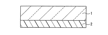
図1は、本発明の近赤外線遮蔽体の一例を示す断面図である。本実施形態の近赤外線遮蔽体は、基材1と、基材1の一方の主面に配置された近赤外線吸収層2から形成されている。
(Embodiment 1)
FIG. 1 is a cross-sectional view showing an example of the near-infrared shield of the present invention. The near-infrared shield of this embodiment is formed of a base 1 and a near-infrared absorbing
基材1は、透光性を有する材料で形成されていれば、その形状や製造方法等は特に限定されない。例えば、ポリエステル系樹脂、ポリカーボネート系樹脂、ポリアクリル酸エステル系樹脂、脂環式ポリオレフィン系樹脂、ポリスチレン系樹脂、ポリ塩化ビニル系樹脂、ポリ酢酸ビニル系樹脂、ポリエーテルスルホン系樹脂、トリアセチルセルロース系樹脂等の材料を、フィルム状又はシート状に加工したものを用いることができる。フィルム状又はシート状に加工する方法としては、押し出し成形、カレンダー成形、圧縮成形、射出成形、上記樹脂を溶剤に溶解させてキャスティングする方法等が挙げられる。基材1の厚さは、通常10μm〜500μm程度である。なお、上記材料には、酸化防止剤、難燃剤、耐熱防止剤、紫外線吸収剤、易滑剤、帯電防止剤等の添加剤が添加されていてもよい。 If the base material 1 is formed with the material which has translucency, the shape, a manufacturing method, etc. will not be specifically limited. For example, polyester resin, polycarbonate resin, polyacrylate resin, alicyclic polyolefin resin, polystyrene resin, polyvinyl chloride resin, polyvinyl acetate resin, polyethersulfone resin, triacetyl cellulose What processed the material, such as resin, into the film form or the sheet form can be used. Examples of the method for processing into a film or sheet include extrusion molding, calendar molding, compression molding, injection molding, and a method in which the above resin is dissolved in a solvent and cast. The thickness of the base material 1 is usually about 10 μm to 500 μm. Note that additives such as antioxidants, flame retardants, heat resistance inhibitors, ultraviolet absorbers, lubricants, and antistatic agents may be added to the above materials.
近赤外線吸収層2は、近赤外線吸収化合物として、スルホン酸イミド誘導体を含むジイモニウム化合物と、下記式(1)で表される構造を有する置換ベンゼンジチオール金属錯体アニオンと下記式(2)で表される構造を有するカチオンとの対イオン結合体からなる化合物とを含めば特に限定されない。
The near-infrared absorbing
但し、式(1)の中で、R1、R2は、炭素数1〜6のアルキル基、炭素数1〜8のアルキルアミノ基、置換又は未置換のモルホリノ基、置換又は未置換のチオモルホリノ基、置換又は未置換のピペラジノ基及び置換又は未置換のフェニル基からなる群から選ばれる少なくとも1つの置換基を示し、Mは遷移金属を示す。
However, in the
但し、式(2)の中で、Q1、Q2は、5員環の含窒素複素環、5員環の含窒素複素環を含む縮合環、6員環の含窒素複素環及び6員環の含窒素複素環を含む縮合環からなる群から選ばれる少なくとも1つの複素環式化合物を示し、R3、R4は炭素数1〜8のアルキル基を示し、nは2、3又は4の数字を示す。 In the formula (2), Q 1 and Q 2 are a 5-membered nitrogen-containing heterocyclic ring, a condensed ring containing a 5-membered nitrogen-containing heterocyclic ring, a 6-membered nitrogen-containing heterocyclic ring and a 6-membered ring. 1 represents at least one heterocyclic compound selected from the group consisting of condensed rings containing a nitrogen-containing heterocyclic ring, R 3 and R 4 represent an alkyl group having 1 to 8 carbon atoms, and n represents 2, 3 or 4 Indicates the number.
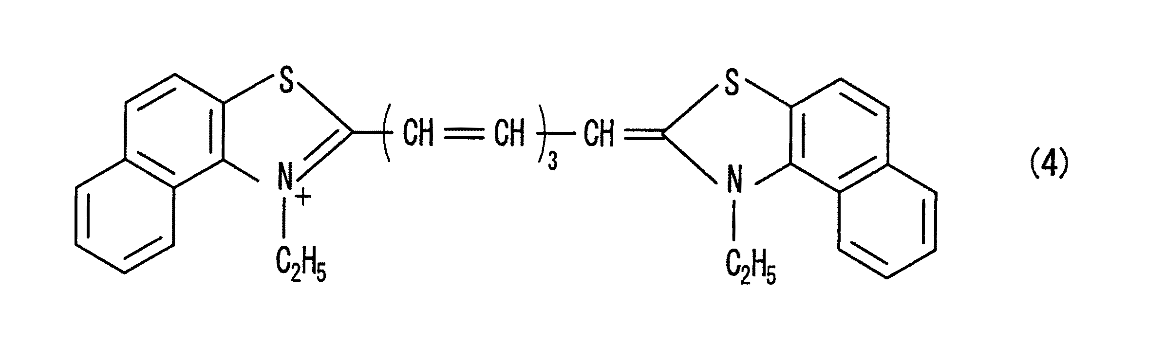
特に、上記式(2)で表される構造を有するカチオンは、下記式(3)〜(5)に示すカチオンを用いることが好ましい。 In particular, the cation having the structure represented by the above formula (2) is preferably a cation represented by the following formulas (3) to (5).
上記ジイモニウム化合物の構造は、例えば、下記式(6)及び(7)で表される化合物を用いることができる。 As the structure of the diimonium compound, for example, compounds represented by the following formulas (6) and (7) can be used.
但し、式(6)及び式(7)の中で、R5〜R12は置換又は未置換のアルキル基を示し、X-、Y2-はそれぞれ1価と2価のカウンターアニオンを示し、nは1又は2の数字を示す。 However, in formula (6) and formula (7), R 5 to R 12 represent a substituted or unsubstituted alkyl group, X − and Y 2− represent monovalent and divalent counter anions, respectively. n represents a number of 1 or 2.
式(6)及び式(7)のカチオン部位の末端の窒素原子に結合しているR5〜R12の少なくとも1つは、分岐鎖構造を有するアルキル基であることが好ましい。また、R5〜R12はそれぞれ異なるアルキル基であっても、一部又は全てが同じアルキル基であってもよい。X-、Y2-は、カウンターアニオンとして、スルホン酸イミド誘導体を含めば特に限定されない。スルホン酸イミド誘導体を含み且つ上記R5〜R12の少なくとも1つが分岐鎖構造を有するアルキル基であるジイモニウム化合物を用いれば、近赤外線の遮蔽性及び可視光の透過性に優れ、高温及び高湿並びに光の照射下においても長期間保存により耐える近赤外線吸収層2が得られる。このスルホン酸イミド誘導体としては特に限定されないが、例えば、パーフロロアルカンスルホン酸イミドイオン等を用いることが好ましく、特に、ビス(トリフルオロメタンスルホニル)イミド酸イオンのようなトリフルオロメタンスルホン酸イミドイオン等を用いることがより好ましい。
It is preferable that at least one of R 5 to R 12 bonded to the terminal nitrogen atom of the cation moiety of formula (6) and formula (7) is an alkyl group having a branched chain structure. R 5 to R 12 may be different alkyl groups, or some or all of them may be the same alkyl group. X − and Y 2− are not particularly limited as long as a sulfonic acid imide derivative is included as a counter anion. If a diimonium compound containing a sulfonic acid imide derivative and at least one of R 5 to R 12 is an alkyl group having a branched chain structure is used, it has excellent near-infrared shielding properties and visible light transmission properties, high temperatures and high humidity. In addition, the near-infrared
また、近赤外線吸収層2は、式(6)のX-が、例えば、フッ素イオン、塩素イオン、臭素イオン、ヨウ素イオン等のハロゲンイオン、チオシアン酸イオン、ヘキサフルオロアンチモン酸イオン、過塩素酸イオン、過ヨウ素酸イオン、硝酸イオン、テトラフルオロホウ酸イオン、ヘキサフルオロリン酸イオン、モリブデン酸イオン、タングステン酸イオン、チタン酸イオン、バナジン酸イオン、リン酸イオン、ホウ酸イオン等の無機イオン、酢酸イオン、乳酸イオン、トリフルオロ酢酸イオン、プロピオン酸イオン、安息香酸イオン、シュウ酸イオン、コハク酸イオン、ステアリン酸イオン等の有機カルボン酸イオン、メタンスルホン酸イオン、トルエンスルホン酸イオン、ナフタレンスルホン酸イオン、クロロベンゼンスルホン酸イオン、ニトロベンゼンスルホン酸イオン、ドデシルスルホン酸イオン、ベンゼンスルホン酸イオン、エタンスルホン酸イオン、トリフルオロメタンスルホン酸イオン等の有機スルホン酸イオン等であるジイモニウム化合物をさらに含んでいてもよい。
The near-infrared
また、近赤外線吸収層2は、式(7)のY2-が、例えば、ナフタレン−1,5−ジスルホン酸イオン、R酸(例えば、2−ナフトール−3,6−ジスルホン酸)イオン、G酸(例えば、7−ヒドロキシナフタレンスルホン酸)イオン、H酸(例えば、1−アミノ−8−ナフト−ル−3,6−ジスルホン酸)イオン、ベンゾイルH酸イオン、p−クロロベンゾイルH酸イオン、クロルアセチルH酸イオン、C酸(例えば、3−アミノ−6−クロロトルエン−4,4−スルホン酸)イオン、p−トルエンスルホニルR酸イオン、ナフタリン−1,6−ジスルホン酸イオン、1−ナフトール−4,8−ジスルホン酸イオン等のナフタレンジスルホン酸誘導体イオン、4,4’−ジアミノスチルベン−2,2’−ジスルホン酸イオン、ナフタル酸イオン、ナフタリン−2,3’−ジカルボン酸イオン、ジフェン酸イオン、スチルベン−4,4’−ジカルボン酸イオン、6−スルホ−2−オキシ−3−ナフトエ酸イオン、アントラキノン−1,8−ジスルホン酸イオン、1,6−ジアミノアントラキノン−2,7−ジスルホン酸イオン、2−(4−スルホニル)−6−アミノベンゾトリアゾール−5−スルホン酸イオン、6−(3−メチル−5−ピラゾニル)−1,3−ジスルホン酸イオン、1−ナフトール−6−(4−アミノ−3−スルホ)アニリノ−3−スルホン酸イオン等の有機酸イオンであるジイモニウム化合物をさらに含んでいてもよい。 Further, in the near-infrared absorbing layer 2, Y 2− in the formula (7) is, for example, naphthalene-1,5-disulfonic acid ion, R acid (for example, 2-naphthol-3,6-disulfonic acid) ion, G Acid (eg, 7-hydroxynaphthalenesulfonic acid) ion, H acid (eg, 1-amino-8-naphthol-3,6-disulfonic acid) ion, benzoyl H acid ion, p-chlorobenzoyl H acid ion, Chloracetyl H acid ion, C acid (for example, 3-amino-6-chlorotoluene-4,4-sulfonic acid) ion, p-toluenesulfonyl R acid ion, naphthalene-1,6-disulfonic acid ion, 1-naphthol -Naphthalenedisulfonic acid derivative ions such as 4,8-disulfonic acid ions, 4,4'-diaminostilbene-2,2'-disulfonic acid ions, naphthalic acid ions Naphthalene-2,3′-dicarboxylic acid ion, diphenic acid ion, stilbene-4,4′-dicarboxylic acid ion, 6-sulfo-2-oxy-3-naphthoic acid ion, anthraquinone-1,8-disulfonic acid ion, 1,6-diaminoanthraquinone-2,7-disulfonic acid ion, 2- (4-sulfonyl) -6-aminobenzotriazole-5-sulfonic acid ion, 6- (3-methyl-5-pyrazonyl) -1,3 -It may further contain a diimonium compound which is an organic acid ion such as a disulfonic acid ion or 1-naphthol-6- (4-amino-3-sulfo) anilino-3-sulfonic acid ion.
上記スルホン酸イミド誘導体を含むジイモニウム化合物は、950nm以上1150nm以下の波長領域に最大吸収波長を有する化合物であれば、より好ましい。また、上記対イオン結合体からなる化合物は、800nm以上900nm以下の波長領域に最大吸収波長を有する化合物であれば、より好ましい。両者を組み合わせることにより、820nm〜1100nmの波長領域におけるほぼ全ての近赤外線を吸収対象にできる。 The diimonium compound containing the sulfonic imide derivative is more preferably a compound having a maximum absorption wavelength in a wavelength region of 950 nm to 1150 nm. The compound comprising the counter ion conjugate is more preferably a compound having a maximum absorption wavelength in the wavelength region of 800 nm to 900 nm. By combining both, almost all near infrared rays in the wavelength region of 820 nm to 1100 nm can be absorbed.
基材1の一方の主面に近赤外線吸収層2を形成する方法は特に限定されず、例えば、ロールコート、ダイコート、エアナイフコート、ブレードコート、スピンコート、リバースコート、グラビアコート等の塗工法、グラビア印刷、スクリーン印刷、オフセット印刷、インクジェット印刷等の印刷法を用いることができる。
The method for forming the near infrared
上記近赤外線吸収層2は、上記ジイモニウム化合物と上記対イオン結合体からなる化合物とを含む近赤外線吸収化合物を分散させる樹脂をさらに含むことがより好ましい。これにより、近赤外線吸収化合物を分散させて基材上に固定化できる。この樹脂としては、アクリル樹脂、ポリウレタン樹脂、ポリ塩化ビニル樹脂、エポキシ樹脂、ポリ酢酸ビニル樹脂、ポリスチレン樹脂、セルロース樹脂、ポリブチラール樹脂、ポリエステル樹脂等を用いることができる。また、これらの樹脂を2種以上ブレンドしたポリマーブレンドを用いることもできる。特に、ガラス転移温度が80℃以上の樹脂を用いると、近赤外線吸収化合物が樹脂により強く固定化され、耐熱性を向上させることができるので好ましい。また、疎水性成分を含む樹脂を併用すれば、耐温湿度特性を向上させることができるのでより一層好ましい。
More preferably, the near-infrared
また、上記近赤外線吸収層2は、上記樹脂を溶解する溶剤をさらに含んでいてもよい。この溶剤は、上記近赤外線吸収化合物及び上記樹脂の溶解性を損なわなければ特に限定されず、例えば、メチルエチルケトン、メチルイソブチルケトン、酢酸エチル、酢酸プロピル、エチルセロソルブ、ブチルセロソルブ、トルエン、キシレン、テトラヒドロキシフラン等を用いることができる。
Moreover, the said near-
上記近赤外線吸収層2は、580nm〜620nmの波長領域に最大吸収波長を有する化合物をさらに含むことがより好ましい。これにより、ネオンの発光を吸収できる。ネオンの発光は、例えばPDPの色再現性を低下させる原因の1つであり、この近赤外線遮蔽体を用いてネオンの発光が吸収されれば、PDPの赤色をより鮮やかに発色させることができる。該化合物は、波長820nm〜1100nmの全領域において近赤外線吸収層2の分光透過率を変化させない化合物であれば特に限定されず、例えば、シアニン系、アズレニウム系、スクワリウム系、ジフェニルメタン系、トリフェニルメタン系、オキサジン系、アジン系、チオピリウム系、ビオローゲン系、アゾ系、アゾ金属錯塩系、アザポルフィリン系、ビスアゾ系、アントラキノン系、フタロシアニン系等の有機色素化合物を用いることができる。また、近赤外線吸収層2が樹脂を含む場合に該化合物は、その樹脂と上記近赤外線吸収化合物との相溶性を変化させない化合物を用いることがより一層好ましい。
More preferably, the near
また、上記近赤外線吸収層2は、540nm〜570nmの波長領域に最大吸収波長を有する化合物をさらに含むことがより好ましい。これにより、例えばディスプレイの明所コントラストが向上する。該化合物は、波長820nm〜1100nmの全領域において近赤外線吸収層2の分光透過率を変化させない化合物であれば特に限定されず、例えば、シアニン系、アズレニウム系、スクワリウム系、ジフェニルメタン系、トリフェニルメタン系、オキサジン系、アジン系、チオピリウム系、ビオローゲン系、アゾ系、アゾ金属錯塩系、アザポルフィリン系、ビスアゾ系、アントラキノン系、フタロシアニン系等の有機色素化合物を用いることができる。また、近赤外線吸収層2が樹脂を含む場合に該化合物は、その樹脂と上記近赤外線吸収化合物との相溶性を変化させない化合物を用いることがより一層好ましい。
Moreover, it is more preferable that the near-infrared
さらに、上記近赤外線吸収層2は、480nm〜500nmの波長領域に最大吸収波長を有する化合物をさらに含むことがより好ましい。これにより、例えば三波長蛍光下でのディスプレイの明所コントラストが向上する。該化合物は、波長820nm〜1100nmの全領域において近赤外線吸収層2の分光透過率を変化させない化合物であれば特に限定されず、例えば、シアニン系、アズレニウム系、スクワリウム系、ジフェニルメタン系、トリフェニルメタン系、オキサジン系、アジン系、チオピリウム系、ビオローゲン系、アゾ系、アゾ金属錯塩系、アザポルフィリン系、ビスアゾ系、アントラキノン系、フタロシアニン系等の有機色素化合物を用いることができる。また、近赤外線吸収層2が樹脂を含む場合に該化合物は、その樹脂と上記近赤外線吸収化合物との相溶性を変化させない化合物を用いることがより一層好ましい。
Furthermore, it is more preferable that the near-infrared
本実施形態の近赤外線遮蔽体は、Haze値が1%以下であることがより好ましい。Haze値が1%を超えると、例えばPDPの前面板として使用した場合、画像の鮮やかさが損なわれるといった不都合が生じる。 As for the near-infrared shielding body of this embodiment, it is more preferable that Haze value is 1% or less. If the haze value exceeds 1%, for example, when used as a front plate of a PDP, there arises a disadvantage that the vividness of the image is impaired.
本実施形態の近赤外線遮蔽体は、波長820nm〜1100nmの領域における分光透過率が、0.5%以上13%以下であることが好ましい。この波長領域における分光透過率が13%を超えると、例えばリモートコントロールの誤作動の原因や、近赤外線遮蔽体の色変化の原因となるため好ましくない。 The near-infrared shield of this embodiment preferably has a spectral transmittance of 0.5% or more and 13% or less in a wavelength region of 820 nm to 1100 nm. If the spectral transmittance in this wavelength region exceeds 13%, for example, it may cause a malfunction of the remote control or a color change of the near-infrared shield, which is not preferable.
近赤外線吸収層2の厚さは、2μm〜15μmが好ましく、3μm〜10μmがより好ましい。近赤外線吸収層2の厚さが2μm未満の場合、近赤外線(波長820nm〜1100nmの領域の発光)の分光透過率を20%以下にするためには樹脂に対する近赤外線吸収化合物の添加量を増加させる必要があり、未溶解の近赤外線吸収化合物が生じてHaze値が大きくなるという問題が生じる。また、厚さが15μmを超える場合、波長820nm〜1100nmの領域における分光透過率を20%以下に維持できるものの近赤外線吸収層2中に遊離した溶剤が残り、この残存溶剤は、経時的に近赤外線吸収化合物を再溶解するため問題となりうる。
The thickness of the near infrared
(実施形態2)
図2は、本発明の近赤外線遮蔽体の他の一例を示す断面図である。図2において、図1に示した近赤外線遮蔽体と同じ構成部材には同じ符号を付し、その説明を省略する。また、同じ部材は同様の効果を有する。
(Embodiment 2)
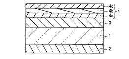
FIG. 2 is a cross-sectional view showing another example of the near-infrared shield of the present invention. In FIG. 2, the same components as those of the near-infrared shield shown in FIG. Moreover, the same member has the same effect.
本実施形態の近赤外線遮蔽体は、基材1と、基材1の一方の主面に配置された近赤外線吸収層2と、この基材1の他方の主面に配置されたハードコート層3と、このハードコート層3の上に配置された反射防止層4から形成されている。また、上記反射防止層4は、屈折率の異なる3層から形成され、ハードコート層3側から中屈折率層4a、高屈折率層4b、低屈折率層4cの順に配置されている。
The near-infrared shield of this embodiment includes a base material 1, a near-infrared
ハードコート層3の材料は、硬度が高く透光性を有する材料であれば特に限定されない。例えば、ウレタン系、メラミン系、エポキシ系、アクリル系等の熱硬化型樹脂組成物、電磁波硬化型樹脂組成物等を用いることができる。特に表面硬度が高い電磁波硬化型樹脂組成物を用いることがより好ましい。また、上記ハードコート層3は、無機微粒子をさらに含むことが好ましい。無機微粒子を含むことによってハードコート層3は、より高い表面硬度が得られるとともに、樹脂等の硬化による収縮を緩和できる。無機微粒子の材料としては、例えば、二酸化珪素(シリカ)、錫ドープ酸化インジウム、アンチモンドープ酸化錫、酸化ジルコニウム等を用いることができる。
The material of the
基材1の上にハードコート層3を形成する方法は特に限定されず、例えば、ロールコート、ダイコート、エアナイフコート、ブレードコート、スピンコート、リバースコート、グラビアコート等の塗工法、グラビア印刷、スクリーン印刷、オフセット印刷、インクジェット印刷等の印刷法を用いることができる。ハードコート層3の厚さは、1μm〜10μmが好ましく、2μm〜7μmがより好ましい。
The method for forming the
反射防止層4の平均反射率は、波長450nm〜650nmの領域において0.05%以上1%以下の範囲、波長650nm〜750nmの領域において0.05%以上1.5%以下の範囲が好ましい。さらに、反射防止層4の反射光の表色は、CIE1976(L*a*b*)表色系において、−8≦a*≦8、−20≦b*≦−2の範囲が好ましく、−4≦a*≦3、−15≦b*≦−4の範囲がより好ましく、−1≦a*≦1、−10≦b*≦−6がより一層好ましい。反射防止層4を上述のように設定することにより、広い波長領域において反射率が低く、反射光の色度が無彩色領域である近赤外線遮蔽体が得られる。また、例えば、近赤外線遮蔽体をディスプレイ用前面板に用いた場合、ディスプレイの表示品位を高品質化できる。
The average reflectance of the
ハードコート層3の上に反射防止層4を形成する方法は特に限定されず、例えば、ロールコート、ダイコート、エアナイフコート、ブレードコート、スピンコート、リバースコート、グラビアコート等の塗工法、グラビア印刷、スクリーン印刷、オフセット印刷、インクジェット印刷等の印刷法を用いることができる。
The method for forming the
中屈折率層4aは、屈折率nmが1.53以上1.65以下の範囲、より好ましくは1.57以上1.63以下の範囲であり、その材料が透光性を有していれば特に限定されない。その材料としては、例えば、屈折率の高い無機微粒子を有機物成分中に均一に分散させたコーティング組成物等を好適に用いることができる。上記有機物成分としては、例えば、熱硬化型樹脂組成物又は電磁波硬化型樹脂組成物等の架橋可能な有機物を用いることができる。また、上記無機微粒子としては、例えば、酸化チタン、酸化錫、酸化インジウム、錫ドープ酸化インジウム(ITO)、アンチモンドープ酸化錫(ATO)、酸化ジルコニウム、酸化亜鉛、酸化セリウム等の微粒子を用いることができる。特に、高い導電性を有するITO微粒子又はATO微粒子を用いれば、中屈折率層4aの帯電を防止する効果が得られるのでより好ましい。
The medium
中屈折率層4aの屈折率nmとその厚さdmとの積nmdm(光学厚さ)は、110nm以上163nm以下の範囲が好ましく、125nm以上150nm以下の範囲がより好ましい。
Product n m d m of the refractive index n m and its thickness d m of the middle
高屈折率層4bは、屈折率nhが1.70以上1.95以下の範囲、より好ましくは1.76以上1.84以下の範囲であり、その材料が透光性を有していれば特に限定されない。その材料としては、例えば、屈折率の最も高い無機微粒子である酸化チタン微粒子を有機物成分中に均一に分散させたコーティング組成物を好適に用いることができる。上記有機物成分としては、例えば、熱硬化型樹脂組成物又は電磁波硬化型樹脂組成物等の架橋可能な有機物を用いることができ、この高屈折率層4bは、コーティング組成物が強固に架橋した膜として形成される。また、酸化チタン微粒子は光触媒作用が弱く、かつ屈折率も高いルチル構造の酸化チタン微粒子を用いることがより好ましい。アナターゼ構造の酸化チタン微粒子は、光触媒作用があり、紫外線の照射によりこの膜を構成する樹脂成分や基材等の有機物を分解してしまうからである。酸化チタン微粒子の量は、硬化後の高屈折率層4bの全重量の50重量%以上65重量%以下が好ましい。また、上記屈折率を満足できるのであれば、上記酸化チタンに、例えば酸化アンチモン、酸化亜鉛、酸化錫等の導電性粒子を添加してもよい。導電性粒子を添加することにより、高屈折率層4bに帯電機能を付与できる。
The high
高屈折率層4bの屈折率nhとその厚さdhとの積nhdh(光学厚さ)は225nm以上325nm以下の範囲が好ましく、250nm以上300nm以下の範囲がより好ましい。
High product n h d h (optical thickness) of the refractive index n h and its thickness d h of the
また、上記高屈折率層4b中の有機物成分の一部は、屈折率が1.60以上1.80以下の範囲、より好ましくは1.65以上1.75以下の範囲である有機物成分であることが好ましい。高屈折率層4b中の無機微粒子の量を低減しても、屈折率を高めることができるからである。無機微粒子の量を低減することにより、高屈折率層4b中における有機物成分の架橋の低下を防止でき、有機物成分の硬化を促進し、この層の耐擦傷性を向上させることができる。上記有機物成分の屈折率が1.60未満では、高屈折率層4b中の微粒子量の低減効果が不十分となり、その屈折率が1.80を超えると反射光の黄色味が強くなる傾向があり好ましくない。屈折率が1.60以上1.80以下の範囲にある高屈折率な有機物成分としては、芳香環、硫黄、臭素等を含む有機化合物等を用いることができ、より具体的には、例えば、ジフェニルスルフィドやその誘導体等を用いることができる。
A part of the organic component in the high
低屈折率層4cは、屈折率nlが1.30以上1.47以下の範囲、より好ましくは1.35以上1.45以下の範囲であり、その材料が透光性を有していれば特に限定されない。その材料としては、例えば、フッ素系又はシリコーン系有機化合物、二酸化珪素(シリカ)、フッ化マグネシウム等の無機微粒子等を有機物成分中に均一に分散させたコーティング組成物を好適に用いることができる。上記有機物成分としては、例えば、熱硬化型樹脂組成物又は電磁波硬化型樹脂組成物等の架橋可能な有機物を用いることができる。特に、電磁波硬化型樹脂組成物として紫外線硬化型樹脂組成物を用いる場合には、窒素等の不活性ガスをパージして、酸素濃度が1000ppm以下になる条件下で紫外線照射を行うことが好ましい。これより、酸素による重合阻害を防止することができる。
The low
低屈折率層4cの屈折率nlとその厚さdlとの積nldl(光学厚さ)は、110nm以上163nm以下の範囲が好ましく、125nm以上150nm以下の範囲がより好ましい。
The product n l d l (optical thickness) of the refractive index n l and the thickness d l of the low
本実施形態の反射防止層4は、外光の反射を低減できるものであれば、上述の構成に特に限定されるものではない。例えば、反射防止層の層数は、反射の程度と反射光の品位、コストに応じて単層、二層、三層構造のように適宜層構造とすることが可能である。一般に、単層構造で反射防止を行うためには、屈折率と厚さの積である光学厚さはλ/4(λは波長を示す。)とする。二層構造の場合、人間の目の視感度の高い波長のみの反射率を低減させるためには、基材側から高屈折率層、低屈折率層の順に積層させて、それぞれの光学厚さはλ/4、λ/4とし、広い波長領域で反射率を低くするためには、基材側から高屈折率層、低屈折率層の順に積層させて、それぞれの光学厚さはλ/2、λ/4とする。三層構造の場合、より広い波長領域で反射率を低くするためには、基材側から中屈折率層、高屈折率層、低屈折率層の順に積層させて、それぞれの光学厚さをλ/4、λ/2、λ/4とすればよい。
The
なお、実施形態1の近赤外線遮蔽体のみでもディスプレイ用の前面板の部材として使用できるが、実施形態2に示したように、反射防止機能等の複数の機能を備えた近赤外線遮蔽体を使用することがより好ましい。
In addition, although only the near-infrared shield of Embodiment 1 can be used as a member of a front plate for a display, as shown in
(実施形態3)
図3は、本発明のディスプレイ用前面板の一例を示す断面図である。本実施形態のディスプレイ用前面板11は、基板12と、基板12の一方の主面に配置された近赤外線遮蔽体13及び他方の主面に配置された電磁波遮蔽体14と、電極(アース)15から形成されている。基板12の材料は、透光性を有する材料であれば特に限定されず、例えば強化ガラス等を用いればよい。近赤外線遮蔽体13としては、例えば、実施形態2の近赤外線遮蔽体をそのまま用いることができる。本実施形態によれば、近赤外線の遮蔽性に優れ、長期間保存しても近赤外線吸収能が低下しない近赤外線遮蔽体の機能と、電磁波遮蔽体の機能とを有するディスプレイ用前面板を得られる。
(Embodiment 3)
FIG. 3 is a sectional view showing an example of the display front plate of the present invention. The display front plate 11 according to the present embodiment includes a substrate 12, a near-infrared shield 13 disposed on one main surface of the substrate 12, an
以下、実施例に基づき本発明をより具体的に説明する。なお、本発明は、以下の実施例に限定されるものではない。 Hereinafter, based on an Example, this invention is demonstrated more concretely. The present invention is not limited to the following examples.
(実施例1)
ジメチルホルムアミド(DMF)30重量部に、N,N,N’,N’−テトラキス(アミノフェニル)−p−フェニレンジアミン3.8重量部と、イソブチルブロミド21重量部と、炭酸カリウム15重量部とを加え、窒素置換させながら80℃で1時間、90℃で7時間反応させ、さらに130℃で1時間反応させた。この反応液を冷却後、濾過を行い、この濾過液にイソプロパノール30重量部を加え、5℃以下で1時間攪拌した。生成した結晶をメタノールで洗浄後、乾燥し、N,N,N’,N’−テトラキス(ジ(p−ジ(イソブチル)アミノフェニル)−p−フェニレンジアミンの結晶2.5重量部を得た。
Example 1
30 parts by weight of dimethylformamide (DMF), 3.8 parts by weight of N, N, N ′, N′-tetrakis (aminophenyl) -p-phenylenediamine, 21 parts by weight of isobutyl bromide, 15 parts by weight of potassium carbonate, Was added, and the reaction was carried out at 80 ° C. for 1 hour, 90 ° C. for 7 hours, and further reacted at 130 ° C. for 1 hour. The reaction solution was cooled and then filtered, and 30 parts by weight of isopropanol was added to the filtrate, followed by stirring at 5 ° C. or lower for 1 hour. The produced crystals were washed with methanol and dried to obtain 2.5 parts by weight of N, N, N ′, N′-tetrakis (di (p-di (isobutyl) aminophenyl) -p-phenylenediamine crystals. .
次に、DMF100重量部に、ビス(トリフルオロメタンスルホン)イミド酸銀10重量部と、上記にて合成したN,N,N’,N’−テトラキス(ジ(p−ジ(イソブチル)アミノフェニル)−p−フェニレンジアミン11.8重量部とを加え、60℃で3時間反応させ、生成した銀を濾過により分離し、この濾過液に水300重量部を添加し、生成した沈殿を再度濾過して洗浄後、乾燥し、ビス(トリフルオロメタンスルホン)イミド酸N,N,N’,N’−テトラキス(ジ(p−ジ(イソブチル)アミノフェニル)−p−フェニレンジイモニウム15.7重量部を得た。このようにして合成したジイモニウム化合物の最大吸収波長及びモル吸光係数を測定したところ、それぞれ1074nm、10500L・mol -1 ・cm-1であった。
Next, 100 parts by weight of DMF, 10 parts by weight of silver bis (trifluoromethanesulfone) imidate, and N, N, N ′, N′-tetrakis (di (p-di (isobutyl) aminophenyl) synthesized above) -11.8 parts by weight of p-phenylenediamine was added, reacted at 60 ° C for 3 hours, the produced silver was separated by filtration, 300 parts by weight of water was added to the filtrate, and the produced precipitate was filtered again. And then dried to obtain 15.7 parts by weight of bis (trifluoromethanesulfone) imidic acid N, N, N ′, N′-tetrakis (di (p-di (isobutyl) aminophenyl) -p-phenylenediimonium. The maximum absorption wavelength and molar extinction coefficient of the diimonium compound synthesized in this way were measured and found to be 1074 nm and 10500 L · mol −1 · cm −1 , respectively.
続いて、基材として、表裏両面を易接着処理した厚さ100μmのポリエチレンテレフタレート(PET)フィルム(東レ社製“U−34”)を準備し、近赤外線吸収層の材料として、上記にて合成したジイモニウム化合物6重量部、前述の式(1)で表される構造を有する置換ベンゼンジチオール金属(銅)錯体アニオンと前述の式(2)で表される構造を有するカチオンとの対イオン結合体からなる化合物(住友精化製“SD50−E04N”、最大吸収波長877nm)1重量部、及び前述の式(1)で表される構造を有する置換ベンゼンジチオール金属(銅)錯体アニオンと前述の式(2)で表される構造を有するカチオンとの対イオン結合体からなる化合物(住友精化製“SD50−E05N”、最大吸収波長833nm)1重量部、アクリル樹脂(三菱レイヨン社製“ダイヤナールBR−52”)100重量部、メチルエチルケトン125重量部、トルエン460重量部を準備した。次に、これらの近赤外線吸収層の材料を混合・撹拌させたコーティング液を、乾燥後の厚さが4μmになるようにマイクログラビアコータを用いて、上記基材上に塗布して近赤外線吸収層を形成し、本実施例の近赤外線遮蔽体を作製した。 Subsequently, as a base material, a polyethylene terephthalate (PET) film (“U-34” manufactured by Toray Industries, Inc.) having a thickness of 100 μm with easy adhesion treatment on both front and back surfaces was prepared, and synthesized above as a material for the near infrared absorption layer. 6 parts by weight of the prepared diimonium compound, a counter ion conjugate of a substituted benzenedithiol metal (copper) complex anion having the structure represented by the above formula (1) and a cation having the structure represented by the above formula (2) 1 part by weight of a compound comprising “SD50-E04N” manufactured by Sumitomo Seika, maximum absorption wavelength 877 nm, and a substituted benzenedithiol metal (copper) complex anion having the structure represented by the above formula (1) and the above formula 1 weight of a compound composed of a counter ion conjugate with a cation having the structure represented by (2) (“SD50-E05N” manufactured by Sumitomo Seika, maximum absorption wavelength 833 nm) , An acrylic resin (Mitsubishi Rayon Co., Ltd. "Dianal BR-52") 100 parts by weight of methyl ethyl ketone 125 parts by weight, was prepared 460 parts by weight of toluene. Next, the coating liquid prepared by mixing and stirring the materials of these near infrared absorption layers is applied onto the substrate using a micro gravure coater so that the thickness after drying becomes 4 μm, and absorbs near infrared rays. The layer was formed and the near-infrared shielding body of the present Example was produced.
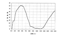
上記近赤外線遮蔽体の分光透過率を分光光度計(日本分光社製“U−Best V−570”)にて測定したところ、図4に示すように、波長820nm〜950nmの領域における分光透過率は10%以下、波長950nm〜1100nmの領域における分光透過率は5%以下であった。また、Haze値は0.8%、透過光の色度(x,y)は(0.3215,0.3464)であった。 When the spectral transmittance of the near-infrared shield was measured with a spectrophotometer (“U-Best V-570” manufactured by JASCO Corporation), as shown in FIG. 4, the spectral transmittance in the wavelength region of 820 nm to 950 nm. Was 10% or less, and the spectral transmittance in a wavelength region of 950 nm to 1100 nm was 5% or less. The Haze value was 0.8%, and the chromaticity (x, y) of transmitted light was (0.3215, 0.3464).
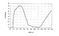
また、上記近赤外線遮蔽体の近赤外線吸収層の上に、紫外線カット機能を有するPETフィルム(東レ社製“ルミラーQT58”、380nmの透過率0.6%)を重ね合わせ、紫外線カット機能を有するPETフィルム側から光を照射させる耐光性試験を行った。具体的には、耐光性試験機(スガ試験機社製“スーパーキセノンウェザーメータSX−75”)を用いて、紫外線カット機能を有するPETフィルム側から、BPT63℃、相対湿度50%の条件下で、キセノン光を、照度60W/m2(300〜400nmの範囲でのエネルギー密度)で16時間照射する照射試験を行った。なお、紫外線カット機能を有するPETフィルムの使用により、上記近赤外線遮蔽体に照射されるキセノン光の波長は380〜1200nmとなる。その耐光性試験後の近赤外線遮蔽体の分光透過率を上記と同様にして測定した。その結果、図5に示すように、波長820nm〜1100nmの領域での分光透過率は、耐光性試験前の分光透過率に比べて、ほとんど変化が認められず、透過光の色度変化は、Δxが0.0011、Δyが0.0023であった。
In addition, on the near-infrared absorbing layer of the near-infrared shield, a PET film having a UV-cutting function ("Lumirror QT58" manufactured by Toray Industries Inc., 380 nm transmittance 0.6%) is superposed to have a UV-cutting function. A light resistance test was performed in which light was irradiated from the PET film side. Specifically, using a light resistance tester (“Super Xenon Weather Meter SX-75” manufactured by Suga Test Instruments Co., Ltd.), from the PET film side having an ultraviolet cut function, under the conditions of BPT 63 ° C. and
ここで、色度変化Δx及びΔyは下記数式から算出した。 Here, the chromaticity changes Δx and Δy were calculated from the following mathematical expressions.
(数1)
Δx=|xint−xend|
Δy=|yint−yend|
但し、上記数式において、xint及びyintは上記耐光性試験前の透過光の色度、xend及びyendは上記耐光性試験後の透過光の色度を表す。
(Equation 1)
Δx = | x int −x end |
Δy = | y int −y end |
In the above formula, x int and y int represent the chromaticity of the transmitted light before the light resistance test, and x end and y end represent the chromaticity of the transmitted light after the light resistance test.
(実施例2)
実施例1の近赤外線吸収層の材料に、ネオン光カット色素(山田化学社製“TAP−2”、最大吸収波長594nm)2.2重量部をさらに加えたこと以外は、実施例1と同様にして近赤外線遮蔽体を作製した。実施例1と同様の方法で分光透過率を測定したところ、波長590nmでの分光透過率は29%、波長820nm〜950nmの領域での分光透過率は15%以下、波長950nm〜1100nmの領域での分光透過率は10%以下であった。また、Haze値は0.8%、透過光の色度(x,y)は(0.2984,0.3401)であった。さらに、実施例1と同様の方法で、上記近赤外線遮蔽体を用いて耐光性試験を行ったところ、波長820nm〜1100nmの領域での分光透過率は、耐光性試験前の分光透過率に比べて、ほとんど変化せず、透過光の色度変化は、Δxが0.0012、Δyが0.0025であった。
(Example 2)
The same as Example 1 except that 2.2 parts by weight of a neon light cut pigment (“TAP-2” manufactured by Yamada Chemical Co., Ltd., maximum absorption wavelength 594 nm) was further added to the material of the near infrared absorption layer of Example 1. Thus, a near-infrared shield was produced. When the spectral transmittance was measured by the same method as in Example 1, the spectral transmittance at a wavelength of 590 nm was 29%, the spectral transmittance at a wavelength of 820 nm to 950 nm was 15% or less, and the wavelength of 950 nm to 1100 nm. The spectral transmittance was 10% or less. The Haze value was 0.8%, and the chromaticity (x, y) of transmitted light was (0.2984, 0.3401). Furthermore, when the light resistance test was performed using the near-infrared shield in the same manner as in Example 1, the spectral transmittance in the wavelength region of 820 nm to 1100 nm was compared with the spectral transmittance before the light resistance test. As a result, the chromaticity change of the transmitted light was Δ12 of 0.0012 and Δ25 of 0.0025.
(実施例3)
実施例2の近赤外線吸収層の材料に、最大吸収波長484nmのスクワリリウム色素0.15重量部と、最大吸収波長552nmのスクワリリウム色素0.3重量部とをさらに加えたこと以外は、実施例1と同様にして近赤外線遮蔽体を作製した。実施例1と同様の方法で分光透過率を測定したところ、波長490nmでの分光透過率は44.5%、波長550nmでの分光透過率は35.0%、波長590nmでの分光透過率は28.5%、波長820nm〜950nmの領域での分光透過率は15%以下、波長950nm〜1100nmの領域での分光透過率は10%以下であった。また、Haze値は0.8%、透過光の色度(x,y)は(0.3110,0.3067)であった。さらに、実施例1と同様の方法で耐光性試験を行ったところ、波長820nm〜1100nmの領域での分光透過率は、耐光性試験前の分光透過率に比べて、ほとんど変化が認められず、透過光の色度変化は、Δxが0.0018、Δyが0.0030であった。
(Example 3)
Example 1 except that 0.15 parts by weight of squarylium dye having a maximum absorption wavelength of 484 nm and 0.3 parts by weight of squarylium dye having a maximum absorption wavelength of 552 nm were further added to the material of the near infrared absorption layer of Example 2. In the same manner, a near-infrared shield was produced. When the spectral transmittance was measured in the same manner as in Example 1, the spectral transmittance at a wavelength of 490 nm was 44.5%, the spectral transmittance at a wavelength of 550 nm was 35.0%, and the spectral transmittance at a wavelength of 590 nm was The spectral transmittance in the region of 28.5%, wavelength 820 nm to 950 nm was 15% or less, and the spectral transmittance in the region of wavelength 950 nm to 1100 nm was 10% or less. The Haze value was 0.8%, and the chromaticity (x, y) of transmitted light was (0.3110, 0.3067). Furthermore, when the light resistance test was performed in the same manner as in Example 1, the spectral transmittance in the wavelength region of 820 nm to 1100 nm hardly changed compared to the spectral transmittance before the light resistance test. As for the chromaticity change of the transmitted light, Δx was 0.0018 and Δy was 0.0030.
(実施例4)
基材に、表裏両面を易接着処理した厚さ100μmの紫外線カット性PETフィルム(東レ社製“ルミラーQT58”)を用いたこと以外は、実施例1と同様にして近赤外線遮蔽体を作製した。
Example 4
A near-infrared shield was prepared in the same manner as in Example 1 except that an ultraviolet-cutting PET film having a thickness of 100 μm with easy adhesion treatment on both sides was used as the substrate (“Lumirror QT58” manufactured by Toray Industries, Inc.). .
次に、シリカ超微粒子を含有したアクリレート系紫外線硬化型ハードコート材(JSR社製“デソライトZ7501”)100重量部と、メチルイソブチルケトン35重量部とを混合・撹拌してコーティング液を調製し、このコーティング液を上記PETフィルムの近赤外線吸収層側とは反対の表面に、マイクログラビアコータを用いてコーティングして乾燥した。その後、紫外線を300mJ/cm2の強度で照射して硬化させ、上記PETフィルムの表面に厚さ4μmのハードコート層を形成した。 Next, 100 parts by weight of an acrylate ultraviolet curable hard coat material containing silica ultrafine particles (“Desolite Z7501” manufactured by JSR) and 35 parts by weight of methyl isobutyl ketone are mixed and stirred to prepare a coating solution. This coating solution was coated on the surface opposite to the near infrared absorption layer side of the PET film using a micro gravure coater and dried. Thereafter, ultraviolet rays were irradiated and cured at an intensity of 300 mJ / cm 2 to form a hard coat layer having a thickness of 4 μm on the surface of the PET film.
次に、無機超微粒子を含有したアクリレート系紫外線硬化型コート材(JSR社製“オプスターTU4005”)100重量部、多官能アクリレート(日本化薬社製“DPHA”)5重量部、及びシクロヘキサノン200重量部を混合・撹拌してコーティング液を調製し、このコーティング液を上記ハードコート層の上に、マイクログラビアコータを用いてコーティングして乾燥した。その後、紫外線を300mJ/cm2の強度で照射して硬化させ、上記ハードコート層の表面に厚さ72μmの中屈折率層(屈折率1.60)を形成した。 Next, 100 parts by weight of an acrylate ultraviolet curable coating material containing inorganic ultrafine particles (“OPSTA TU4005” manufactured by JSR), 5 parts by weight of polyfunctional acrylate (“DPHA” manufactured by Nippon Kayaku Co., Ltd.), and 200 weights of cyclohexanone The coating liquid was prepared by mixing and stirring the parts, and this coating liquid was coated on the hard coat layer using a microgravure coater and dried. Thereafter, ultraviolet rays were irradiated and cured at an intensity of 300 mJ / cm 2 to form a medium refractive index layer (refractive index 1.60) having a thickness of 72 μm on the surface of the hard coat layer.
続いて、酸化チタン超微粒子(石原テクノ社製“TTO55(A)”)30重量部、ジメチルアミノエチルメタクリレート(共栄社化学社製“ライトエステルDM”)1重量部、リン酸基含有メタクリレート(日本化薬社製“KAYAMER PM−21”)4重量部、及びシクロヘキサノン65重量部を混合した組成物を、サンドグラインドミルを用いて分散させて酸化チタン超微粒子分散体を調製し、これにアクリレート系紫外線硬化型ハードコート材(三洋化成工業社製“サンラッドH−601R”)15重量部、メチルイソブチルケトン600重量部を配合分散してコーティング液を調製した。このコーティング液を上記中屈折率層の上に、マイクログラビアコータを用いてコーティングして乾燥した。その後、紫外線を500mJ/cm2の強度で照射して硬化させ、上記中屈折率層の表面に厚さ130μmの高屈折率層(固形分中に占める酸化チタン微粒子の量60重量%、屈折率1.80)を形成した。 Subsequently, 30 parts by weight of titanium oxide ultrafine particles (“TTO55 (A)” manufactured by Ishihara Techno Co., Ltd.), 1 part by weight of dimethylaminoethyl methacrylate (“Light Ester DM” manufactured by Kyoeisha Chemical Co., Ltd.), phosphate group-containing methacrylate (Nipponization) A composition obtained by mixing 4 parts by weight of “KAYAMER PM-21” manufactured by Yakuhin Co., Ltd. and 65 parts by weight of cyclohexanone is dispersed using a sand grind mill to prepare a titanium oxide ultrafine particle dispersion. A coating liquid was prepared by blending and dispersing 15 parts by weight of a curable hard coat material (“Sunrad H-601R” manufactured by Sanyo Chemical Industries) and 600 parts by weight of methyl isobutyl ketone. This coating solution was coated on the medium refractive index layer using a micro gravure coater and dried. Thereafter, ultraviolet rays are irradiated and cured at an intensity of 500 mJ / cm 2 , and a high refractive index layer having a thickness of 130 μm is formed on the surface of the middle refractive index layer (the amount of titanium oxide fine particles in the solid content is 60% by weight, the refractive index. 1.80) was formed.
さらに、フッ素系ポリマー含有熱硬化型低屈折率反射防止材(JSR社製“オプスターTT1006”)100重量部と、メチルイソブチルケトン20重量部とを混合・撹拌してコーティング液を調製し、このコーティング液を上記高屈折率層の上に、マイクログラビアコータを用いてコーティングして乾燥した。その後、120℃で6分間熱処理を行い、上記高屈折率層の表面に厚さ92μmの低屈折率層(屈折率1.41)を形成した。 Further, a coating solution is prepared by mixing and stirring 100 parts by weight of a fluoropolymer-containing thermosetting low-refractive index antireflective material (“OPSTA TT1006” manufactured by JSR) and 20 parts by weight of methyl isobutyl ketone. The liquid was coated on the high refractive index layer using a micro gravure coater and dried. Thereafter, heat treatment was performed at 120 ° C. for 6 minutes to form a low refractive index layer (refractive index: 1.41) having a thickness of 92 μm on the surface of the high refractive index layer.
以上のように、ハードコート層と、中屈折率層、高屈折率層及び低屈折率層からなる反射防止層とを備えた本実施例の反射防止/近赤外線遮蔽複合体を作製した。 As described above, the antireflection / near-infrared shielding composite of this example comprising a hard coat layer and an antireflection layer comprising a medium refractive index layer, a high refractive index layer and a low refractive index layer was produced.
次に、この反射防止/近赤外線遮蔽複合体の反射防止層側からの反射率を分光光度計(日本分光社製“U−Best V−570型”)を用いて測定したところ、図6に示すように、波長450nm〜650nmの領域における平均反射率は1%以下、波長650nm〜750nmの領域における平均反射率は1.5%以下であった。また、反射光の表色は、CIE1976(L*a*b*)表色系において、a*は−0.68、b*は−8.96であった。また、実施例1と同様の方法で、本実施例の反射防止/近赤外線遮蔽複合体の分光透過率を測定したところ、図7に示すように、波長850nm〜900nmの領域での分光透過率は10%以下、波長900nm〜1100nmの領域での分光透過率は10%以下であった。また、Haze値は0.9%で、透過光の色度(x,y)は(0.3235,0.3484)であった。さらに、上記反射防止/近赤外線遮蔽複合体の反射防止層の上に、紫外線カット機能を有するPETフィルム(東レ社製“ルミラーQT58”、380nmの透過率0.6%)を重ね合わせ、反射防止層側から実施例1と同様の照射条件でキセノン光を照射して、耐光性試験を行ったところ、波長820nm〜1100nmの領域での分光透過率は、耐光性試験前の分光透過率に比べて、ほとんど変化が認められず、透過光の色度変化は、Δxが0.0012、Δyは0.0023であった。 Next, the reflectance from the antireflection layer side of the antireflection / near infrared shielding composite was measured using a spectrophotometer (“U-Best V-570 type” manufactured by JASCO Corporation). As shown, the average reflectance in the wavelength region of 450 nm to 650 nm was 1% or less, and the average reflectance in the wavelength region of 650 nm to 750 nm was 1.5% or less. The color of reflected light was CIE 1976 (L * a * b * ) color system, where a * was −0.68 and b * was −8.96. Further, when the spectral transmittance of the antireflection / near-infrared shielding composite of this example was measured in the same manner as in Example 1, the spectral transmittance in the wavelength region of 850 nm to 900 nm as shown in FIG. Was 10% or less, and the spectral transmittance in the wavelength region of 900 nm to 1100 nm was 10% or less. The Haze value was 0.9%, and the chromaticity (x, y) of transmitted light was (0.3235, 0.3484). Further, an anti-reflection layer of the anti-reflection / near-infrared shielding composite is overlaid with a PET film having a UV-cutting function ("Lumirror QT58" manufactured by Toray Industries Inc., transmittance of 0.6% at 380 nm) to prevent reflection. When a light resistance test was performed by irradiating xenon light under the same irradiation conditions as in Example 1 from the layer side, the spectral transmittance in the wavelength region of 820 nm to 1100 nm was compared with the spectral transmittance before the light resistance test. Almost no change was observed, and the chromaticity change of the transmitted light was Δ12 of 0.0012 and 0.0023 of Δy.
(実施例5)
基材に、表裏両面を易接着処理した厚さ100μmの紫外線カット性PETフィルム(東レ社製“ルミラーQT58”)を用いたこと以外は、実施例2と同様にして近赤外線遮蔽体を作製し、上記PETフィルムの近赤外線吸収層側とは反対の表面に、実施例4と同様にしてハードコート層、中屈折率層、高屈折率層、低屈折率層を順次積層した。この近赤外線遮蔽体の近赤外線吸収層側を厚さ2.3mmのガラス基板の一方の主面に貼り合わせ、さらに電磁波シールドメッシュフィルム(線幅10μm、線間隔250μm)を、上記ガラス基板の近赤外線遮蔽体側の主面の反対面に貼り合わせ、本実施例の電子ディスプレイ用光学フィルタ(ディスプレイ用前面板)を作製した。
(Example 5)
A near-infrared shield was prepared in the same manner as in Example 2 except that a UV-cutting PET film with a thickness of 100 μm ("Lumirror QT58" manufactured by Toray Industries, Inc.) with easy adhesion treatment on both sides was used for the base material. A hard coat layer, a medium refractive index layer, a high refractive index layer, and a low refractive index layer were sequentially laminated on the surface opposite to the near infrared absorption layer side of the PET film in the same manner as in Example 4. The near-infrared absorbing layer side of this near-infrared shield is bonded to one main surface of a 2.3 mm thick glass substrate, and an electromagnetic wave shielding mesh film (
このフィルタをカラープラズマディスプレイに組み込み、電子情報技術産業協会規格のカラープラズマディスプレイモジュールの測定方法(EIAJED−2710A)で明室(明所)コントラスト比を測定したところ104であった。 This filter was incorporated into a color plasma display, and the contrast ratio of the bright room (light place) was measured by the measurement method (EIAJED-2710A) of the color plasma display module of the Japan Electronics and Information Technology Industries Association standard, and it was 104.
(実施例6)
基材に、表裏両面を易接着処理した厚さ100μmの紫外線カット性PETフィルム(東レ社製“ルミラーQT58”)を用いたこと以外は、実施例3と同様にして近赤外線遮蔽体を作製し、上記PETフィルムの近赤外線吸収層側とは反対の表面に、実施例4と同様にしてハードコート層、中屈折率層、高屈折率層、低屈折率層を順次積層した。この近赤外線遮蔽体の近赤外線吸収層側を厚さ2.3mmのガラス基板の一方の主面に貼り合わせ、さらに電磁波シールドメッシュフィルム(線幅10μm、線間隔250μm)を、上記ガラス基板の近赤外線遮蔽体側の主面の反対面に貼り合わせ、本実施例の電子ディスプレイ用光学フィルタ(ディスプレイ用前面板)を作製した。
(Example 6)
A near-infrared shield was prepared in the same manner as in Example 3 except that a UV-cutting PET film with a thickness of 100 μm (“Lumirror QT58” manufactured by Toray Industries, Inc.) with easy adhesion treatment on both sides was used for the base material. A hard coat layer, a medium refractive index layer, a high refractive index layer, and a low refractive index layer were sequentially laminated on the surface opposite to the near infrared absorption layer side of the PET film in the same manner as in Example 4. The near-infrared absorbing layer side of this near-infrared shield is bonded to one main surface of a 2.3 mm thick glass substrate, and an electromagnetic wave shielding mesh film (
このフィルタを実施例5と同様の方法で明室(明所)コントラスト比を測定したところ149であった。 When this filter was measured for the bright room (light) contrast ratio in the same manner as in Example 5, it was 149.
(比較例1)
実施例1のジイモニウム化合物に代えて、カウンターアニオンとして六フッ化アンチモンイオンを含むジイモニウム化合物(日本カーリット社製“CIR−1081”)6重量部を用いたこと以外は実施例1と同様にして、本比較例の近赤外線遮蔽体を作製した。
(Comparative Example 1)
Instead of the diimonium compound of Example 1, the same procedure as in Example 1 was used except that 6 parts by weight of a diimonium compound (“CIR-1081” manufactured by Nippon Carlit Co., Ltd.) containing antimony hexafluoride ion as a counter anion was used. A near-infrared shield of this comparative example was produced.
上記近赤外線遮蔽体の分光透過率を実施例1と同様の方法で測定したところ、図8に示すように、波長820nm〜950nmの領域における分光透過率は10%以下、波長950nm〜1100nmの領域における分光透過率は5%以下であった。また、Haze値は0.8%、透過光の色度(x,y)は(0.3217,0.3468)であった。 When the spectral transmittance of the near-infrared shield was measured in the same manner as in Example 1, as shown in FIG. 8, the spectral transmittance in the wavelength range of 820 nm to 950 nm was 10% or less, and the wavelength range of 950 nm to 1100 nm. The spectral transmittance at 5 was 5% or less. The Haze value was 0.8%, and the chromaticity (x, y) of transmitted light was (0.3217, 0.3468).
また、実施例1と同様の方法で耐光性試験を行った。その耐光性試験後の近赤外線遮蔽体の分光透過率を上記と同様にして測定した。その結果、図9に示すように、波長820nm〜830nmの領域での分光透過率が13%を超え、透過光の色度変化は、Δxが0.0053、Δyが0.0080であり、色の変化が大きかった。 Further, a light resistance test was conducted in the same manner as in Example 1. The spectral transmittance of the near-infrared shield after the light resistance test was measured in the same manner as described above. As a result, as shown in FIG. 9, the spectral transmittance in the wavelength region of 820 nm to 830 nm exceeds 13%, and the chromaticity change of the transmitted light is Δx is 0.0053, Δy is 0.0080, The change was great.
(比較例2)
実施例1の2種類の対イオン結合体からなる化合物に代えて、シアニン化合物(林原生物化学研究所製“NK124”、最大吸収波長928nm)0.4重量部及びシアニン化合物(山田化学社製“IR−301”、最大吸収波長830nm)0.4重量部を用いたこと以外は実施例1と同様にして、本比較例の近赤外線遮蔽体を作製した。
(Comparative Example 2)
Instead of the compound composed of the two types of counterion conjugates of Example 1, 0.4 part by weight of a cyanine compound (“NK124” manufactured by Hayashibara Biochemical Research Laboratory, maximum absorption wavelength 928 nm) and a cyanine compound (manufactured by Yamada Chemical Co., Ltd. “ IR-301 ″, maximum absorption wavelength 830 nm) A near-infrared shield of this comparative example was produced in the same manner as in Example 1 except that 0.4 part by weight was used.
上記近赤外線遮蔽体の分光透過率を実施例1と同様の方法で測定したところ、波長820nm〜950nmの領域における分光透過率は15%以下、波長950nm〜1100nmの領域における分光透過率は10%以下であった。また、Haze値は0.8%、透過光の色度(x,y)は(0.3200,0.3442)であった。また、実施例1と同様の方法で耐光性試験を行った。その耐光性試験後の近赤外線遮蔽体の分光透過率を上記と同様にして測定した。その結果、図10に示すように、波長820nm〜830nmの領域における分光透過率が13%を超え、透過光の色度変化は、Δxが0.007、Δyが0.009であった。 When the spectral transmittance of the near-infrared shield was measured in the same manner as in Example 1, the spectral transmittance in the wavelength region of 820 nm to 950 nm was 15% or less, and the spectral transmittance in the wavelength region of 950 nm to 1100 nm was 10%. It was the following. The Haze value was 0.8%, and the chromaticity (x, y) of transmitted light was (0.3200, 0.3442). Further, a light resistance test was conducted in the same manner as in Example 1. The spectral transmittance of the near-infrared shield after the light resistance test was measured in the same manner as described above. As a result, as shown in FIG. 10, the spectral transmittance in the wavelength region of 820 nm to 830 nm exceeded 13%, and the chromaticity change of the transmitted light was Δx of 0.007 and Δy of 0.009.
以上説明したように本発明は、耐光性試験を行っても、高い近赤外線遮蔽性を有し、近赤外線の吸収能が低下しない近赤外線遮蔽体を提供できる。また、本発明の近赤外線遮蔽体を用いることにより、電子ディスプレイ、特にPDPに好適なディスプレイ用前面板を提供できる。 As described above, the present invention can provide a near-infrared shield that has high near-infrared shielding properties and does not deteriorate near-infrared absorbing ability even when a light resistance test is performed. Further, by using the near-infrared shield of the present invention, a display front plate suitable for electronic displays, particularly PDPs, can be provided.
1 基材
2 近赤外線吸収層
3 ハードコート層
4 反射防止層
4a 中屈折率層
4b 高屈折率層
4c 低屈折率層
11 ディスプレイ用前面板
12 基板
13 近赤外線遮蔽体
14 電磁波遮蔽体
15 電極
DESCRIPTION OF SYMBOLS 1
Claims (9)
前記近赤外線吸収層は、カウンターアニオンとしてスルホン酸イミド誘導体アニオンを含むジイモニウム化合物と、下記式(1)で表される構造を有する置換ベンゼンジチオール金属錯体アニオンと下記式(2)で表される構造を有するカチオンとの対イオン結合体からなる化合物とを含み、
前記ジイモニウム化合物のカチオン部位の末端の窒素原子に結合している置換基の少なくとも1つは、分岐鎖構造を有するアルキル基であることを特徴とする近赤外線遮蔽体。
The near-infrared absorption layer, a diimmonium compound containing a sulfonic acid imide derivative anion as a counter anion, represented by the following formula (1) substituted benzene having a structure represented by the dithiol metal complex anions and the following formula (2) Structure Comprising a counter ion conjugate with a cation having
The near-infrared shield, wherein at least one of the substituents bonded to the nitrogen atom at the end of the cation moiety of the diimonium compound is an alkyl group having a branched chain structure.
Priority Applications (4)
| Application Number | Priority Date | Filing Date | Title |
|---|---|---|---|
| JP2005292688A JP4086871B2 (en) | 2004-11-18 | 2005-10-05 | Near-infrared shield and display front plate |
| TW094137128A TW200630230A (en) | 2004-11-18 | 2005-10-24 | Near-infrared shield and display front plate |
| US11/280,344 US7662490B2 (en) | 2004-11-18 | 2005-11-17 | Near-infrared shield and display front plate |
| KR1020050110312A KR101201899B1 (en) | 2004-11-18 | 2005-11-17 | A shied from near infrared rays and a front-plate of display devices using the same |
Applications Claiming Priority (2)
| Application Number | Priority Date | Filing Date | Title |
|---|---|---|---|
| JP2004334904 | 2004-11-18 | ||
| JP2005292688A JP4086871B2 (en) | 2004-11-18 | 2005-10-05 | Near-infrared shield and display front plate |
Related Child Applications (1)
| Application Number | Title | Priority Date | Filing Date |
|---|---|---|---|
| JP2007126922A Division JP2007310383A (en) | 2004-11-18 | 2007-05-11 | Near-infrared shield and display front plate |
Publications (2)
| Publication Number | Publication Date |
|---|---|
| JP2006171705A JP2006171705A (en) | 2006-06-29 |
| JP4086871B2 true JP4086871B2 (en) | 2008-05-14 |
Family
ID=36386701
Family Applications (1)
| Application Number | Title | Priority Date | Filing Date |
|---|---|---|---|
| JP2005292688A Expired - Fee Related JP4086871B2 (en) | 2004-11-18 | 2005-10-05 | Near-infrared shield and display front plate |
Country Status (4)
| Country | Link |
|---|---|
| US (1) | US7662490B2 (en) |
| JP (1) | JP4086871B2 (en) |
| KR (1) | KR101201899B1 (en) |
| TW (1) | TW200630230A (en) |
Families Citing this family (14)
| Publication number | Priority date | Publication date | Assignee | Title |
|---|---|---|---|---|
| JP4654685B2 (en) * | 2004-12-28 | 2011-03-23 | 東洋紡績株式会社 | Near-infrared absorbing film and near-infrared absorbing filter |
| JP4678635B2 (en) * | 2005-02-10 | 2011-04-27 | 東レフィルム加工株式会社 | Optical film |
| JP2007070498A (en) * | 2005-09-08 | 2007-03-22 | Sumitomo Seika Chem Co Ltd | Light absorbing pigment solution |
| DE102006024383A1 (en) * | 2006-05-24 | 2007-11-29 | Fraunhofer-Gesellschaft zur Förderung der angewandten Forschung e.V. | Device for increasing individual comfort in an aircraft |
| KR101249597B1 (en) * | 2006-09-06 | 2013-04-01 | 린텍 가부시키가이샤 | Infrared-ray absorption film |
| JP2008070468A (en) * | 2006-09-12 | 2008-03-27 | Hitachi Maxell Ltd | Optical film and front surface plate for display using the same |
| JP2008122524A (en) * | 2006-11-09 | 2008-05-29 | Hitachi Maxell Ltd | Optical film and display front board using it |
| WO2008081892A1 (en) * | 2006-12-28 | 2008-07-10 | Nippon Shokubai Co., Ltd. | Selectively light-transmitting filter |
| JP2008176143A (en) * | 2007-01-19 | 2008-07-31 | Hitachi Maxell Ltd | Optical film and front board for display using same |
| US20080305282A1 (en) * | 2007-06-06 | 2008-12-11 | Hitachi Maxell, Ltd. | Antireflection film and display front plate using the same |
| JP5768410B2 (en) * | 2010-04-22 | 2015-08-26 | 信越化学工業株式会社 | Near infrared light absorbing film forming material and laminated film |
| JP6533437B2 (en) * | 2015-09-08 | 2019-06-19 | マクセルホールディングス株式会社 | Transparent thermal insulation member and method of manufacturing the same |
| KR101892941B1 (en) * | 2017-09-28 | 2018-08-30 | (주)유티아이 | optical filter and manufacturing method of optical filter thereby |
| JPWO2021085372A1 (en) * | 2019-11-01 | 2021-05-06 |
Family Cites Families (12)
| Publication number | Priority date | Publication date | Assignee | Title |
|---|---|---|---|---|
| JPH0291043A (en) * | 1988-09-29 | 1990-03-30 | Yoshitomi Pharmaceut Ind Ltd | Preparation of salicylic acid derivative |
| JP3298505B2 (en) | 1998-04-30 | 2002-07-02 | 東洋紡績株式会社 | Infrared absorption filter |
| MY123910A (en) * | 1998-08-10 | 2006-06-30 | Sumitomo Bakelite Co | Transparent electromagnetic wave shield |
| JP2001134003A (en) * | 1999-10-29 | 2001-05-18 | Nippon Paper Industries Co Ltd | Sheet for electrophotographic overhead projector |
| US6548177B2 (en) * | 2000-03-15 | 2003-04-15 | Nitto Denko Corporation | Transparent shock-absorbing laminate and flat panel display using the same |
| JP2003021715A (en) | 2001-05-01 | 2003-01-24 | Bridgestone Corp | Near ir absorbing film |
| DE60236424D1 (en) * | 2001-05-01 | 2010-07-01 | Bridgestone Corp | ABSORPTION FILMS FOR THE NEAR INFRARED AREA |
| WO2003005076A1 (en) | 2001-07-04 | 2003-01-16 | Nippon Kayaku Kabushiki Kaisha | Diimonium salt compound, and near-infrared ray absorbing filter and optical information recording medium |
| JP2003327865A (en) | 2002-05-16 | 2003-11-19 | Sumitomo Seika Chem Co Ltd | Near infrared light-absorbing pigment and near infrared light-absorbing material using the same |
| JP4303030B2 (en) * | 2002-10-17 | 2009-07-29 | 住友精化株式会社 | Light absorbing dye and light absorbing material using the same |
| AU2003280844A1 (en) | 2002-11-22 | 2004-06-18 | Japan Carlit Co., Ltd. | Coloring matter absorbing near-infrared ray and filter for cutting off near-infrared ray |
| AU2004287652A1 (en) * | 2003-11-10 | 2005-05-19 | Nippon Kayaku Kabushiki Kaisha | Diimonium salt compound and use thereof |
-
2005
- 2005-10-05 JP JP2005292688A patent/JP4086871B2/en not_active Expired - Fee Related
- 2005-10-24 TW TW094137128A patent/TW200630230A/en not_active IP Right Cessation
- 2005-11-17 US US11/280,344 patent/US7662490B2/en not_active Expired - Fee Related
- 2005-11-17 KR KR1020050110312A patent/KR101201899B1/en not_active IP Right Cessation
Also Published As
| Publication number | Publication date |
|---|---|
| JP2006171705A (en) | 2006-06-29 |
| TW200630230A (en) | 2006-09-01 |
| KR101201899B1 (en) | 2012-11-15 |
| TWI357380B (en) | 2012-02-01 |
| US7662490B2 (en) | 2010-02-16 |
| KR20060055408A (en) | 2006-05-23 |
| US20060105175A1 (en) | 2006-05-18 |
Similar Documents
| Publication | Publication Date | Title |
|---|---|---|
| JP4086871B2 (en) | Near-infrared shield and display front plate | |
| EP1496375B1 (en) | Composition for optical film comprising a near-infrared absorbing dye and a quencher | |
| WO2006046497A1 (en) | Optical filter and its applications, and porphyrin compound used in optical filter | |
| US20060051586A1 (en) | Film for PDP filter, PDP filter comprising the same and plasma display panel produced by using the PDP filter | |
| JP2008176143A (en) | Optical film and front board for display using same | |
| JP4471275B2 (en) | Near-infrared absorbing composition and near-infrared absorbing filter | |
| KR100845726B1 (en) | Filter for image display device | |
| JP5289813B2 (en) | Phthalocyanine compounds | |
| KR20000035490A (en) | Near infrared absorption composition | |
| KR100951524B1 (en) | Optical filter for display apparatus | |
| JP4292048B2 (en) | Near-infrared shield and display front plate using the same | |
| JP2003139946A (en) | Near ir ray absorbing filter | |
| JP2007310383A (en) | Near-infrared shield and display front plate | |
| JP2006284630A (en) | Near-infrared ray absorbing laminate | |
| JP2006137933A (en) | Near infrared ray-absorbing coating agent and near infrared ray-absorbing laminate given by using the same | |
| JP2008070468A (en) | Optical film and front surface plate for display using the same | |
| JP2010008497A (en) | Near-infrared shielding body and front plate for display using the same | |
| JP2008111939A (en) | Optical film and front board for display using the same | |
| JP2006341204A (en) | Method for manufacturing near infrared ray shielding body and plate-like body for display | |
| JP2006137934A (en) | Near infrared ray-absorbing coating agent and near infrared ray-absorbing laminate given by using the same | |
| JP2001261991A (en) | Organic metal complex, infrared light-absorbing filter using the same and filter for plasma display panel | |
| JP2006163172A (en) | Near ir shield and front face plate for display | |
| JP2009244291A (en) | Optical filter | |
| JP2006137935A (en) | Near infrared ray-absorbing coating agent and near infrared ray-absorbing laminate given by using the same | |
| JP2007079453A (en) | Filter for display and display |
Legal Events
| Date | Code | Title | Description |
|---|---|---|---|
| A871 | Explanation of circumstances concerning accelerated examination |
Free format text: JAPANESE INTERMEDIATE CODE: A871 Effective date: 20061124 |
|
| A975 | Report on accelerated examination |
Free format text: JAPANESE INTERMEDIATE CODE: A971005 Effective date: 20070126 |
|
| A131 | Notification of reasons for refusal |
Free format text: JAPANESE INTERMEDIATE CODE: A131 Effective date: 20070313 |
|
| A521 | Written amendment |
Free format text: JAPANESE INTERMEDIATE CODE: A523 Effective date: 20070511 |
|
| A131 | Notification of reasons for refusal |
Free format text: JAPANESE INTERMEDIATE CODE: A131 Effective date: 20070605 |
|
| A02 | Decision of refusal |
Free format text: JAPANESE INTERMEDIATE CODE: A02 Effective date: 20070918 |
|
| A521 | Written amendment |
Free format text: JAPANESE INTERMEDIATE CODE: A523 Effective date: 20071116 |
|
| A521 | Written amendment |
Free format text: JAPANESE INTERMEDIATE CODE: A523 Effective date: 20080115 |
|
| A61 | First payment of annual fees (during grant procedure) |
Free format text: JAPANESE INTERMEDIATE CODE: A61 Effective date: 20080219 |
|
| FPAY | Renewal fee payment (event date is renewal date of database) |
Free format text: PAYMENT UNTIL: 20110228 Year of fee payment: 3 |
|
| R150 | Certificate of patent or registration of utility model |
Free format text: JAPANESE INTERMEDIATE CODE: R150 |
|
| FPAY | Renewal fee payment (event date is renewal date of database) |
Free format text: PAYMENT UNTIL: 20110228 Year of fee payment: 3 |
|
| FPAY | Renewal fee payment (event date is renewal date of database) |
Free format text: PAYMENT UNTIL: 20110228 Year of fee payment: 3 |
|
| FPAY | Renewal fee payment (event date is renewal date of database) |
Free format text: PAYMENT UNTIL: 20120229 Year of fee payment: 4 |
|
| FPAY | Renewal fee payment (event date is renewal date of database) |
Free format text: PAYMENT UNTIL: 20120229 Year of fee payment: 4 |
|
| FPAY | Renewal fee payment (event date is renewal date of database) |
Free format text: PAYMENT UNTIL: 20120229 Year of fee payment: 4 |
|
| FPAY | Renewal fee payment (event date is renewal date of database) |
Free format text: PAYMENT UNTIL: 20130228 Year of fee payment: 5 |
|
| FPAY | Renewal fee payment (event date is renewal date of database) |
Free format text: PAYMENT UNTIL: 20130228 Year of fee payment: 5 |
|
| FPAY | Renewal fee payment (event date is renewal date of database) |
Free format text: PAYMENT UNTIL: 20130228 Year of fee payment: 5 |
|
| FPAY | Renewal fee payment (event date is renewal date of database) |
Free format text: PAYMENT UNTIL: 20140228 Year of fee payment: 6 |
|
| R250 | Receipt of annual fees |
Free format text: JAPANESE INTERMEDIATE CODE: R250 |
|
| R250 | Receipt of annual fees |
Free format text: JAPANESE INTERMEDIATE CODE: R250 |
|
| R250 | Receipt of annual fees |
Free format text: JAPANESE INTERMEDIATE CODE: R250 |
|
| R250 | Receipt of annual fees |
Free format text: JAPANESE INTERMEDIATE CODE: R250 |
|
| LAPS | Cancellation because of no payment of annual fees |