JP2008264372A - Game machine - Google Patents

Game machine Download PDF

Info

Publication number
JP2008264372A
JP2008264372A JP2007114536A JP2007114536A JP2008264372A JP 2008264372 A JP2008264372 A JP 2008264372A JP 2007114536 A JP2007114536 A JP 2007114536A JP 2007114536 A JP2007114536 A JP 2007114536A JP 2008264372 A JP2008264372 A JP 2008264372A
Authority
JP
Japan
Prior art keywords
board
game
display
led
gaming machine
Prior art date
Legal status (The legal status is an assumption and is not a legal conclusion. Google has not performed a legal analysis and makes no representation as to the accuracy of the status listed.)
Withdrawn
Application number
JP2007114536A
Other languages
Japanese (ja)
Other versions
JP2008264372A5 (en
Inventor
Kishiyo Oike
規晶 大池
Morihiro Sawada
盛弘 澤田
Nobuaki Fukumoto
信明 福元
Current Assignee (The listed assignees may be inaccurate. Google has not performed a legal analysis and makes no representation or warranty as to the accuracy of the list.)
Sanyo Bussan Co Ltd
Original Assignee
Sanyo Bussan Co Ltd
Priority date (The priority date is an assumption and is not a legal conclusion. Google has not performed a legal analysis and makes no representation as to the accuracy of the date listed.)
Filing date
Publication date
Application filed by Sanyo Bussan Co Ltd filed Critical Sanyo Bussan Co Ltd
Priority to JP2007114536A priority Critical patent/JP2008264372A/en
Publication of JP2008264372A publication Critical patent/JP2008264372A/en
Publication of JP2008264372A5 publication Critical patent/JP2008264372A5/ja
Withdrawn legal-status Critical Current

Links

Images

Landscapes

  • Pinball Game Machines (AREA)

Abstract

<P>PROBLEM TO BE SOLVED: To provide a game machine which enables easier discovery of any misassembly of a controller in a type equipped with the controller. <P>SOLUTION: A Pachinko game machine has the main controller 162. The main controller 162 is provided with a board box 163 comprising a box base 171 and a box cover 172 while the main control board 173 is installed being housed into the board box 163. The main control board 173 is electrically connected to other devices and the other devices are controlled by the main control board 173 to carry on games. In the arrangement, the board box 163 is provided with a portion bulged ahead of the Pachinko game machine further from a board housing part 192 for housing the main control board 173. A certificate stamp 197 for board sticks to the portion and is made visually recognizable from ahead of the Pachinko game machine. <P>COPYRIGHT: (C)2009,JPO&INPIT

Description

本発明は、遊技機に関するものである。   The present invention relates to a gaming machine.

遊技機の一種として、例えばパチンコ機や、メダル使用又は球使用のスロットマシンが知られている。これら遊技機は、その背面部や内部に制御装置を備えている。制御装置は遊技機を構成する機器と電気的に接続されており、制御装置がそれら機器を制御することにより遊技が進行することとなる。   As a kind of gaming machine, for example, a pachinko machine or a slot machine using medals or balls is known. These gaming machines are provided with a control device on the back or inside thereof. The control device is electrically connected to the devices constituting the gaming machine, and the game proceeds by the control device controlling these devices.

例えばパチンコ機では、遊技領域に設けられた入賞口に遊技球が入球した場合における賞球の個数は制御装置に予め記憶されており、入賞口に遊技球が入球した場合には制御装置による制御に基づいて賞球の払い出しが行われる。また、例えば表示画面を有する図柄表示ユニットが設けられた構成においては、制御装置による制御に基づいて表示画面における表示が行われる。また、多量の遊技球の払い出しといった特典が付与される特別遊技状態(大当たり状態)への移行確率は制御装置に予め記憶されており、制御装置における抽選処理に基づいて特別遊技状態への移行が行われる(例えば、特許文献1参照)。   For example, in a pachinko machine, the number of prize balls when a game ball enters a prize opening provided in the game area is stored in advance in the control device, and when a game ball enters the prize opening, the control device The award ball is paid out based on the control by. For example, in the structure provided with the symbol display unit which has a display screen, the display on a display screen is performed based on control by a control apparatus. In addition, the probability of transition to a special gaming state (hit state) to which a privilege such as paying out a large amount of game balls is given is stored in the control device in advance, and the transition to the special gaming state is performed based on the lottery process in the control device (For example, refer to Patent Document 1).

ここで、上述した賞球の払い出し個数や、表示画面における表示内容や、特別遊技状態への移行確率などは、パチンコ機の機種毎に決められており、機種毎に固有の制御装置が設けられている。また、同一機種において、例えば、表示画面における表示内容などは同じとしながら、特別遊技状態への移行確率などを変更した複数の型式が設けられており、この場合、型式毎に固有の制御装置が設けられている。
特開2000−70446号公報
Here, the number of prize balls to be paid out, the display content on the display screen, the probability of transition to the special gaming state, etc. are determined for each model of the pachinko machine, and a unique control device is provided for each model. ing. In addition, in the same model, for example, there are provided a plurality of types in which the display contents on the display screen are the same and the transition probability to the special gaming state is changed. In this case, a unique control device is provided for each type. Is provided.
JP 2000-70446 A

上記構成において、制御装置の外観上の形状等が類似していると、当該制御装置の組み付け間違いが発生する可能性がある。特に、型式のみが異なる遊技機においては、組み付け作業の効率化や部材管理の適正化などといった面から、制御装置の外観上の形状などが統一化されている場合があり、この場合、制御装置の組み付け間違いが発生する可能性は高くなる。   In the above configuration, if the external shape of the control device is similar, an assembly error of the control device may occur. In particular, in game machines that differ only in the type, the appearance of the control device may be unified from the standpoints of improving the efficiency of assembly work and optimizing member management. In this case, the control device There is a high possibility that an assembly error will occur.

制御装置の組み付け間違いが発生するときとしては、例えば、遊技機の組み立て時において、異なる機種の遊技機の組み立てや異なる型式の遊技機の組み立てが交互に行われる場合などである。また、例えば、遊技ホールにおいて制御装置の交換が行われる場合などである。そして、上記のとおり制御装置は遊技機の背面部や内部に設けられているため、組み付け間違いが発生した場合には発見が容易ではなく、その状態が放置されてしまうおそれがある。   For example, when the assembly error of the control device occurs, when assembling a gaming machine, assembly of different types of gaming machines or assembly of different types of gaming machines are performed alternately. Also, for example, when a control device is exchanged in a game hall. And since the control apparatus is provided in the back part and the inside of a game machine as mentioned above, when an assembly mistake occurs, it is not easy to find and there is a possibility that the state is left unattended.

本発明は上記例示した事情等に鑑みてなされたものであり、制御装置を備えた遊技機において、制御装置の組み付け間違いの発見を容易に行うことが可能となる遊技機を提供することを目的とするものである。   The present invention has been made in view of the above-mentioned circumstances and the like, and an object of the present invention is to provide a gaming machine that can easily find an assembly error of a control device in a gaming machine equipped with a control device. It is what.

以下、上記課題を解決するのに有効な手段等につき、必要に応じて効果等を示しつつ説明する。なお以下においては、理解の容易のため、発明の実施形態において対応する構成を括弧書き等で適宜示すが、この括弧書き等で示した具体的構成に限定されるものではない。   Hereinafter, effective means for solving the above-described problems will be described while showing effects and the like as necessary. In the following, for easy understanding, the corresponding configuration in the embodiment of the invention is appropriately shown in parentheses, but is not limited to the specific configuration shown in parentheses.

手段1.遊技機前面体(前扉枠14、ドアブロック503、前面扉601)よりも後方に設けられた制御装置(主制御装置162,403,524,641)により作動が制御される遊技機において、
前記制御装置は、当該制御装置の設置対象を特定する場合に用いられる特定用情報を表示する特定用表示部(基板用証紙197)を備えており、
当該特定用表示部における表示内容を、前記遊技機前面体に設けられた窓部(遊技領域用窓部20)を通じて遊技機前方から視認可能としたことを特徴とする遊技機。
Means 1. In a gaming machine whose operation is controlled by a control device (main control devices 162, 403, 524, 641) provided behind the front body of the gaming machine (front door frame 14, door block 503, front door 601),
The control device includes a specifying display unit (substrate certificate paper 197) for displaying specifying information used when specifying an installation target of the control device.
A gaming machine characterized in that display contents on the specifying display part can be visually recognized from the front of the gaming machine through a window part (game area window part 20) provided in the front body of the gaming machine.

手段1によれば、制御装置には特定用表示部が設けられており、この特定用表示部にて表示されている特定用情報は遊技機前面体に設けられた窓部を通じて遊技機前方から視認可能となっている。これにより、例えば遊技機の組み立て時においては組み立て完了後に遊技機前方から特定用表示部を視認することで、制御装置の組み付け間違いが生じているか否かを容易に確認することができる。また、例えば遊技ホールにおいては設置状態にある遊技機の前方から特定用表示部を視認することで、制御装置の組み付け間違いが生じているか否かを容易に確認することができる。   According to the means 1, the control device is provided with the specifying display unit, and the specifying information displayed on the specifying display unit is transmitted from the front of the gaming machine through the window unit provided on the front body of the gaming machine. Visible. Thus, for example, when the gaming machine is assembled, it is possible to easily confirm whether or not the control device is assembled incorrectly by visually recognizing the specifying display unit from the front of the gaming machine after the assembly is completed. Further, for example, in a game hall, it is possible to easily confirm whether or not a control device is assembled incorrectly by visually recognizing the specifying display unit from the front of the gaming machine in the installed state.

手段2.手段1において、前記特定用情報は、遊技機の機種毎に又は同一機種における型式毎に固有の情報として設定されている情報であることを特徴とする遊技機。   Mean 2. In the means 1, the specifying information is information set as information unique to each model of the gaming machine or for each model in the same model.

手段2によれば、特定用情報を遊技機前方から視認することで、本来とは異なる機種の制御装置が組み付けられているか又は本来とは異なる型式の制御装置が組み付けられているかを容易に確認することができる。   According to the means 2, it is easy to confirm whether a control device of a different model from the original or a control device of a different type is installed by visually recognizing the specific information from the front of the gaming machine. can do.

手段3.手段1又は2において、前記制御装置の設置対象は予め定められた基準用情報を少なくとも表示する基準用表示部(盤用証紙107)を備えているとともに、当該基準用表示部における表示内容が遊技機前方から視認可能であり、
前記特定用情報は、正規の設置対象の基準用表示部における前記基準用情報である又は前記基準用情報を含む情報であることを特徴とする遊技機。
Means 3. In the means 1 or 2, the installation target of the control device includes a reference display unit (board certificate 107) for displaying at least predetermined reference information, and the display content on the reference display unit is a game. Visible from the front of the machine,
The gaming machine according to claim 1, wherein the specifying information is the reference information in the reference display unit to be properly installed or information including the reference information.

手段3によれば、特定用表示部における表示内容と基準用表示部における表示内容とを遊技機前方から見比べることにより、制御装置の組み付け間違いが生じているか否かを容易に確認することができる。   According to the means 3, it is possible to easily confirm whether or not there is an error in assembling the control device by comparing the display content on the specifying display unit and the display content on the reference display unit from the front of the gaming machine. .

手段4.手段1乃至3のいずれかにおいて、前記特定用表示部はその表面に前記特定用情報が記された札片であることを特徴とする遊技機。   Means 4. In any one of the means 1 to 3, the specifying display unit is a bill having the specifying information on the surface thereof.

手段4によれば、特定用表示部は札片であるため、比較的簡素な構成により上記優れた効果を得ることができる。   According to the means 4, since the specifying display unit is a bill piece, the above-described excellent effect can be obtained with a relatively simple configuration.

手段5.手段4において、前記札片はその裏面が、前記制御装置における遊技機前方を向く周面に外側から貼り付けられていることを特徴とする遊技機。   Means 5. The gaming machine according to claim 4, wherein a back surface of the bill piece is affixed from the outside to a circumferential surface facing the front of the gaming machine in the control device.

手段5によれば、札片を制御装置の周面に外側から貼り付けることで、制御装置に特定用表示部としての機能を付与することができ、比較的簡素な構成により上記優れた効果を得ることができる。   According to the means 5, by sticking the bill pieces to the peripheral surface of the control device from the outside, the control device can be given a function as a display unit for identification, and the above-described excellent effect can be obtained with a relatively simple configuration. Obtainable.

手段6.手段1乃至5のいずれかにおいて、前記遊技機前面体は、支持対象(本体枠13、外枠501、筐体602)に対して開閉可能に支持されており、
前記特定用表示部における表示内容を、前記遊技機前面体を前記支持対象に対して閉鎖した状態において前記窓部を通じて遊技機前方から視認可能としたことを特徴とする遊技機。
Means 6. In any one of means 1 to 5, the gaming machine front body is supported so as to be openable and closable with respect to a support target (the main body frame 13, the outer frame 501, and the housing 602).
A gaming machine characterized in that display contents on the specifying display part can be viewed from the front of the gaming machine through the window part in a state in which the gaming machine front body is closed with respect to the support target.

手段6の遊技機では、制御装置自体を目視により確認するためには、遊技機前面体の開放操作を行う必要がある。これに対して、特定用表示部における表示内容は、遊技機前面体を支持対象に対して閉鎖した状態において遊技機前方から視認することができるため、制御装置の組み付け間違いが生じているか否かを容易に確認することができる。   In the gaming machine of means 6, it is necessary to perform an opening operation of the front body of the gaming machine in order to visually confirm the control device itself. On the other hand, the display content on the specifying display unit can be viewed from the front of the gaming machine with the gaming machine front body closed with respect to the support target, so whether or not a control device assembly error has occurred. Can be easily confirmed.

手段7.手段1乃至6のいずれかにおいて、遊技を実行する遊技装置(遊技盤81,401、リール装置522、リールユニット611)を前記遊技機前面体の後方に備えていることを特徴とする遊技機。   Means 7. A gaming machine according to any one of means 1 to 6, wherein a gaming device (game board 81, 401, reel device 522, reel unit 611) for executing a game is provided behind the front body of the gaming machine.

遊技機前面体の後方に遊技装置を備えた遊技機に対して本発明を適用することができる。   The present invention can be applied to a gaming machine provided with a gaming device behind a gaming machine front body.

手段8.手段7において、前記窓部を通じて前記遊技装置における遊技を視認可能とするとともに、前記特定用表示部における表示内容を視認可能としたことを特徴とする遊技機。   Means 8. The gaming machine according to claim 7, wherein a game in the gaming device can be visually recognized through the window portion, and a display content on the specifying display portion can be visually recognized.

手段8の遊技機では、遊技者は、遊技装置において実行される遊技を、窓部を通じて視認する。この窓部は遊技機前方から視認し易い位置に設けられるのが一般的である。当該構成において、特定用表示部における表示内容を、窓部を通じて視認可能としたことにより、特定表示部における表示内容の視認性が高められる。   In the gaming machine of means 8, the player visually recognizes the game executed in the gaming device through the window. In general, the window portion is provided at a position that is easily visible from the front of the gaming machine. In the said structure, the visibility of the display content in a specific display part is improved by making the display content in the display part for specification visible through a window part.

手段9.手段7又は8において、遊技球が流下する遊技領域が前面に形成された遊技板(遊技盤81,401)を前記遊技装置として備えているとともに、当該遊技板の後方に前記制御装置が設置されており、
さらに、前記遊技板において前記特定用表示部における表示内容を視認可能とする部位が、遊技機の正面視において遊技球が流下する範囲内に含まれていないことを特徴とする遊技機。
Means 9. The means 7 or 8 includes a game board (game board 81, 401) having a game area in which a game ball flows down formed on the front as the game apparatus, and the control device is installed behind the game board. And
Further, the gaming machine is characterized in that a portion of the gaming board that allows the display contents on the specifying display unit to be visually recognized is not included in a range in which a gaming ball flows down in a front view of the gaming machine.

手段9の遊技機では、遊技領域を遊技球が流下することにより遊技が行われ、遊技者は窓部を通じてその遊技球の流下態様を視認する。また、制御装置が遊技板の後方に設置されているため、遊技ホールに設置状態にある遊技機において制御装置は遊技機後側に位置することとなり、制御装置に対する不正行為が行いづらくなっている。   In the gaming machine of means 9, a game is played when the game ball flows down in the game area, and the player visually recognizes the flow mode of the game ball through the window. In addition, since the control device is installed behind the game board, the control device is located on the rear side of the gaming machine in the game machine installed in the game hall, and it is difficult for the control device to perform illegal acts. .

この場合に、遊技板において特定用表示部における表示内容を視認可能とする部位が設けられているため、上記のように制御装置が設置された構成において特定用表示部における表示内容が遊技機前方から視認可能となっている。また、上記視認可能とする部位が、遊技機の正面視において遊技球が流下する範囲内に含まれていないため、遊技領域を流下する遊技球によって特定用表示部における表示内容が遮られることはなく、遊技中であっても当該特定用表示部の視認性が確保される。   In this case, the game board is provided with a part that allows the display content on the specifying display unit to be visually recognized. Therefore, in the configuration in which the control device is installed as described above, the display content on the specifying display unit is forward of the gaming machine. Is visible. In addition, since the part that can be visually recognized is not included in the range in which the game ball flows down in the front view of the gaming machine, the display content on the specifying display unit is blocked by the game ball flowing down the game area. In addition, the visibility of the specific display unit is ensured even during a game.

手段10.手段7乃至9のいずれかにおいて、遊技球が流下する遊技領域が前面に形成された遊技板(遊技盤401)を前記遊技装置として備えているとともに、当該遊技板の後方に前記制御装置が設置されており、
前記特定用表示部における表示内容が前記窓部及び前記遊技板を透過するように、透明性を有する材料により前記遊技板を形成したことを特徴とする遊技機。
Means 10. In any one of the means 7 to 9, a game board (game board 401) in which a game area in which a game ball flows down is formed on the front surface is provided as the game apparatus, and the control device is installed behind the game board. Has been
A gaming machine, wherein the game board is formed of a material having transparency so that display contents on the specifying display part are transmitted through the window part and the game board.

手段10の遊技機では、遊技領域を遊技球が流下することにより遊技が行われ、遊技者は窓部を通じてその遊技球の流下態様を視認する。また、制御装置が遊技板よりも後方に設置されているため、遊技ホールに設置状態にある遊技機において制御装置は遊技機後側に位置することとなり、制御装置に対する不正行為が行いづらくなっている。   In the gaming machine of means 10, a game is played by the game ball flowing down in the game area, and the player visually recognizes the flow-down mode of the game ball through the window. In addition, since the control device is installed behind the game board, in the gaming machine installed in the game hall, the control device is located on the rear side of the gaming machine, and it is difficult to perform an illegal act on the control device. Yes.

この場合に、特定用表示部における表示内容が窓部及び遊技板を透過するように、透明性を有する材料により遊技板が形成されている。これにより、特定用表示部における表示内容を遊技機前方から視認することができる。   In this case, the game board is formed of a material having transparency so that the display content on the specifying display part is transmitted through the window part and the game board. Thereby, the display content in the display part for identification can be visually recognized from the front of the gaming machine.

手段11.手段10において、前記遊技板の後方には、表示画面(表示画面402a)にて絵柄を可変表示する絵柄表示装置(図柄表示装置402)を備えており、前記遊技板が透明性を有する材料により形成されていることにより当該遊技板を通じて前記表示画面における絵柄の可変表示が視認可能となっており、
前記特定用表示部における表示内容が前記表示画面における表示と前後方向に並ばないように、前記特定用表示部の設置位置を設定したことを特徴とする遊技機。
Means 11. The means 10 is provided with a pattern display device (design display device 402) for variably displaying a pattern on a display screen (display screen 402a) behind the game board, and the game board is made of a material having transparency. By being formed, the variable display of the pattern on the display screen is visible through the game board,
A gaming machine characterized in that an installation position of the specifying display unit is set so that display contents on the specifying display unit do not line up with the display on the display screen in the front-rear direction.

手段11の遊技機では、透明性を有する遊技板の後方に絵柄表示装置を設置する構成であるため、遊技板に開口を形成して絵柄表示装置を設置する構成に比して表示画面の大型化が図られる。この場合に、上記手段10の構成を備え、特定用表示部における表示内容は遊技板及び窓部を透過することにより遊技機前方から視認可能となっている。つまり、絵柄表示装置の表示画面の大型化を図るための構成を利用して、特定用表示部における表示内容を遊技機前方から視認可能とすることができる。   The gaming machine of the means 11 has a configuration in which the picture display device is installed behind the transparent gaming board, so that the display screen is larger than the construction in which an opening is formed in the gaming board and the picture display device is installed. Is achieved. In this case, the configuration of the means 10 is provided, and the display content on the specifying display unit is visible from the front of the gaming machine by passing through the game board and the window unit. That is, it is possible to make the display content on the specifying display unit visible from the front of the gaming machine using a configuration for increasing the size of the display screen of the picture display device.

また、本構成においては、特定用表示部における表示内容が表示画面における表示と前後方向に並ばないように構成されている。したがって、両表示のうち一方の表示により他方の表示が遮られてしまうことが防止され、各表示の視認性を共に良好なものとすることができる。   Further, the present configuration is configured such that the display content on the specifying display unit does not line up with the display on the display screen in the front-rear direction. Therefore, it is possible to prevent the other display from being blocked by one of the two displays, and to improve the visibility of each display.

手段12.手段11において、前記遊技領域の下部に設けられ、当該遊技領域を流下した遊技球が入球可能な入球部(一般入賞口82、可変入賞装置83、作動口84、アウト口87)と、
当該入球部の後方であって前記遊技板の裏面側に設けられ、入球部に入球した遊技球を排出する排出通路部(排出通路部408)と、
前記遊技板における前記入球部が設けられた下部領域の表面又は裏面の少なくとも一方に設けられ、当該下部領域よりも後方に設けられた前記排出通路部を視認不可とする遮蔽手段(遮蔽フィルム413)と、
を備えており、
前記遊技板よりも後方であって前記下部領域よりも上方に前記絵柄表示装置を設置するとともに、
前記制御装置を、前記下部領域の後方であって前記絵柄表示装置の下方に設置し、
前記遮蔽手段を、前記特定用表示部における表示内容を視認可能とする部位を除いて設けたことを特徴とする遊技機。
Means 12. In the means 11, a ball entry portion (general winning port 82, variable winning device 83, operating port 84, out port 87) provided at a lower portion of the gaming area and capable of entering a game ball flowing down the gaming area;
A discharge passage portion (discharge passage portion 408) that is provided behind the ball entry portion and on the back side of the game board and discharges the game ball that has entered the ball entry portion;
Shielding means (shielding film 413) that is provided on at least one of the front surface or the back surface of the lower region where the ball entry portion is provided in the game board, and that makes the discharge passage portion provided behind the lower region invisible. )When,
With
While installing the picture display device behind the game board and above the lower region,
The control device is installed behind the lower region and below the picture display device,
A gaming machine, characterized in that the shielding means is provided except for a portion where the display contents on the specifying display portion can be visually recognized.

手段12の遊技機では、遊技領域には入球部が設けられており、遊技領域を流下した遊技球の一部は当該入球部に入球することとなる。そして、この入球部に入球した遊技球は遊技板の裏面側に設けられた排出通路部を介して排出される。また、遊技板における入球部が設けられた下部領域に対しては、遮蔽手段が設けられていることにより、排出通路部を遊技機前方から視認しづらくなっており、遊技機の美観の好適化が図られている。   In the gaming machine of the means 12, the game area is provided with a ball entry section, and a part of the game balls flowing down the game area enter the ball entry section. And the game ball which entered this entrance part is discharged | emitted via the discharge passage part provided in the back surface side of the game board. In addition, the lower area of the game board where the ball entry portion is provided is provided with a shielding means, which makes it difficult to visually recognize the discharge passage portion from the front of the gaming machine. It is planned.

当該構成において、絵柄表示装置が遊技板よりも後方であって下部領域よりも上方に設置されているとともに、下部領域の後方であって絵柄表示装置の下方に制御装置が設置されている。そして、遮蔽手段は、特定用表示部における表示内容を視認可能とする部位を除いて設けられている。これにより、遊技機の美観の好適化を図るための構成を利用して、絵柄表示装置の表示画面と特定用表示部における表示内容とが前後に重ならないようにすることができる。   In this configuration, the design display device is installed behind the game board and above the lower region, and the control device is installed behind the lower region and below the design display device. And the shielding means is provided except the site | part which can visually recognize the display content in the display part for identification. Thus, the configuration for optimizing the aesthetics of the gaming machine can be used so that the display screen of the pattern display device and the display content on the specifying display unit do not overlap each other.

手段13.手段1乃至12のいずれかにおいて、前記制御装置は制御基板(主制御基板173、554、645)を基板ボックス(基板ボックス163、553、644)に収容してなり、
前記基板ボックスは、前記制御基板を収容する基板収容領域(基板収容部192)と、当該基板収容領域よりも前方に膨出させて形成された前方膨出領域(発光体収容部193)と、を備えており、
当該前方膨出領域に前記特定用表示部を設けたことを特徴とする遊技機。
Means 13. In any one of means 1 to 12, the control device accommodates a control board (main control boards 173, 554, 645) in a board box (board boxes 163, 553, 644),
The substrate box includes a substrate accommodation region (substrate accommodation portion 192) that accommodates the control substrate, a front bulge region (light emitter housing portion 193) formed to bulge forward from the substrate accommodation region, With
A gaming machine, wherein the specifying display portion is provided in the front bulge area.

手段13によれば、基板ボックスに基板収容領域と前方膨出領域とが設けられており、前方膨出領域に特定用表示部が設けられていることにより、制御基板の位置を極力遊技機後側としつつ、特定用表示部の位置を極力遊技機前側とすることができる。制御基板への防犯性の観点からは制御基板の位置を遊技機後側とすることが好ましく、特定用表示部における表示内容の視認性の観点からは特定用表示部の位置を遊技機前側とすることが好ましく、本構成によれば、この相反する要望をともに実現することができる。   According to the means 13, the board storage area and the front bulging area are provided in the board box, and the specifying display part is provided in the front bulging area, so that the position of the control board is as much as possible after the gaming machine. The position of the specifying display portion can be as far as possible in front of the gaming machine. From the viewpoint of security against the control board, it is preferable that the position of the control board is the rear side of the gaming machine, and from the viewpoint of the visibility of the display content on the specifying display part, the position of the specifying display part is the front side of the gaming machine. Preferably, according to this configuration, both conflicting demands can be realized.

手段14.手段13において、遊技を実行する遊技装置(遊技盤81)を支持する支持体(本体枠13)を前記遊技機前面体の後方に備えており、
前記遊技装置、前記支持体又は前記遊技装置と前記支持体との境界部分に、前後方向に貫通した開口部(凹部711)を形成し、
前記基板収容部が前記支持体の後方に位置するとともに、前記前方膨出領域が前記開口部内に入り込むように、前記制御装置を設置したことを特徴とする遊技機。
Means 14. The means 13 includes a support body (main body frame 13) for supporting a gaming device (game board 81) for executing a game behind the front body of the gaming machine,
An opening (concave portion 711) penetrating in the front-rear direction is formed in a boundary portion between the gaming apparatus, the support body, or the gaming apparatus and the support body,
A gaming machine characterized in that the control unit is installed so that the substrate housing portion is located behind the support and the front bulge region enters the opening.

手段14によれば、基板収容部が支持体の後方に位置していることにより、制御基板に対する遊技機前方からの不正行為を抑制することができる。当該構成において、特定用表示部が、遊技装置、支持体又は遊技装置と支持体との境界部分に形成された開口部に入り込んでいるため、特定用表示部における表示内容が支持体又は遊技装置により遮られないようにすることができ、特定用表示部における表示内容を遊技機前方から視認することができる。   According to the means 14, since the board | substrate accommodating part is located in the back of a support body, the illegal act from the game machine front with respect to a control board can be suppressed. In this configuration, since the specifying display unit enters the opening formed in the boundary portion between the gaming device, the support body, or the gaming device and the supporting body, the display content in the specifying display unit is the support body or gaming device. The display content on the specifying display unit can be viewed from the front of the gaming machine.

以上説明した手段1乃至14の各手段に代えて又は加えて、以下の各手段を適用してもよい。   The following means may be applied instead of or in addition to the means 1 to 14 described above.

手段15.基板ボックス(基板ボックス163、553、644)に制御基板(主制御基板173、554、645)を収容してなる制御装置(主制御装置162、403、524、641)を、遊技機前面体(前扉枠14、ドアブロック503、前面扉601)よりも後方に備えた遊技機において、
前記制御基板が動作している場合に動作するとともに動作中において予め定められた表示を行う表示手段(LED182a〜182c,411,560,651等)を、前記基板ボックスに収容させて設け、
前記表示手段における表示を、前記遊技機前面体を通じて遊技機前方から視認可能としたことを特徴とする遊技機。
Means 15. A control device (main control devices 162, 403, 524, 641) in which a control board (main control substrates 173, 554, 645) is housed in a substrate box (board boxes 163, 553, 644) is connected to a front body ( In the gaming machine provided behind the front door frame 14, door block 503, front door 601),
Display means (LEDs 182a to 182c, 411, 560, 651, etc.) that operates when the control board is operating and performs a predetermined display during the operation are provided in the board box,
A gaming machine characterized in that the display on the display means is visible from the front of the gaming machine through the gaming machine front body.

手段15の遊技機では、制御装置により他の機器が制御されることにより遊技が実行される。この場合に、基板ボックスに表示手段が設けられている。そして、表示手段は制御基板が動作している場合に動作し、その動作中において予め定められた表示を行う。これにより、表示手段を確認することで、制御装置に代えて不正基板に他の機器が接続されているか否かを把握することができる。   In the gaming machine of the means 15, the game is executed by controlling other devices by the control device. In this case, display means is provided in the substrate box. The display means operates when the control board is operating, and performs a predetermined display during the operation. Thereby, by confirming the display means, it is possible to grasp whether or not another device is connected to the unauthorized board instead of the control device.

また、表示手段における表示は遊技機前方から視認可能となっている。したがって、表示手段の確認を遊技機前方から行うことができ、上記不正基板を用いた不正行為が行われているか否かの確認作業の作業性の向上を図ることができる。   Further, the display on the display means is visible from the front of the gaming machine. Therefore, the display means can be confirmed from the front of the gaming machine, and the workability of the confirmation work of whether or not the illegal act using the illegal board is being performed can be improved.

さらにまた、表示手段は基板ボックス内に収容されている。基板ボックス外に表示手段を設ける構成も想定されるが、この場合、上記不正基板を用いた不正行為を行うとともに、表示手段に対しても不正を行う行為が想定される。そうすると、上記不正行為の発見作業が正確に行えなくなってしまう。これに対して、表示手段を基板ボックス内に収容することで、表示手段に対して不正を行うためには基板ボックスを開放する必要が生じ、その作業が手間となることで、かかる行為を思いとどまらせることが可能となる。   Furthermore, the display means is accommodated in the substrate box. Although the structure which provides a display means outside a board | substrate box is also assumed, while performing the cheating act using the said unjust board | substrate, the act which cheats also on a display means is assumed. If it does so, the discovery operation | work of the said fraud will not be performed correctly. On the other hand, by accommodating the display means in the board box, it is necessary to open the board box in order to perform fraud on the display means, and the work is troublesome. It becomes possible to make it.

手段16.手段15において、前記制御基板に接続された配線を介して当該制御基板に電力を供給する電力供給手段(電源及び発射制御基板321、電源装置534等)を備え、
前記表示手段は、前記制御基板から供給される電力により動作することを特徴とする遊技機。
Means 16. Means 15 includes power supply means (power supply and launch control board 321, power supply device 534, etc.) for supplying power to the control board via wiring connected to the control board,
The gaming machine is characterized in that the display means is operated by electric power supplied from the control board.

手段16によれば、表示手段は制御基板から供給される電力により動作するものであるため、制御基板と電力供給手段との電気的な接続が解除された場合には、自ずと表示手段が動作しなくなる。不正基板を用いた不正行為においては、制御装置(制御基板)に対する電気的な接続を全て不正基板に付け代えることが行われることがあり、この場合、電力供給手段と制御装置との電気的な接続も解除される。当該不正行為が行われた場合には、上記のとおり自ずと表示手段が動作しなくなることで、当該不正行為が行われたことを容易に発見することができる。   According to the means 16, since the display means operates by the electric power supplied from the control board, when the electrical connection between the control board and the power supply means is released, the display means operates by itself. Disappear. In an unauthorized act using an unauthorized board, all the electrical connections to the control device (control board) may be replaced with the unauthorized board. In this case, the electrical connection between the power supply means and the control device may be performed. The connection is also released. When the fraudulent act is performed, the display means does not operate as described above, so that the fraudulent act can be easily detected.

手段17.手段15又は16において、前記基板ボックス内に、前記表示手段の表示制御を実行する表示制御手段(CPU311における第1〜第3LEDの点灯処理、第1LED制御処理、第2LED制御処理、第3LED制御処理を実行する機能)を設けたことを特徴とする遊技機。   Means 17. In the means 15 or 16, display control means for executing display control of the display means in the board box (first to third LED lighting processing, first LED control processing, second LED control processing, third LED control processing in the CPU 311) A gaming machine characterized by providing a function for

手段17によれば、表示制御手段によって制御されることにより、表示手段において予め定められた表示が行われる。この場合、表示制御手段は基板ボックス内に収容されている。基板ボックス外に表示制御手段を設ける構成も想定されるが、この場合、上記不正基板を用いた不正行為を行うとともに、表示制御手段に対しても不正を行う行為が想定される。そうすると、上記不正行為の発見作業が正確に行えなくなってしまう。これに対して、表示制御手段を基板ボックス内に収容することで、表示制御手段に対して不正を行うためには基板ボックスを開放する必要が生じ、その作業が手間となることで、かかる行為を思いとどまらせることが可能となる。   According to the means 17, a predetermined display is performed on the display means by being controlled by the display control means. In this case, the display control means is accommodated in the substrate box. A configuration in which the display control means is provided outside the board box is also assumed. In this case, an illegal act using the illegal board is also assumed, and an illegal action is also assumed for the display control means. If it does so, the discovery operation | work of the said fraud will not be performed correctly. On the other hand, by accommodating the display control means in the board box, it is necessary to open the board box in order to perform fraud against the display control means. Can be discouraged.

手段18.手段17において、前記制御基板は、当該制御基板と配線を介して電気的に接続された他の機器の制御処理を実行する演算装置(CPU311)を備えており、
当該演算装置が前記表示制御手段を有していることを特徴とする遊技機。
Means 18. In the means 17, the control board includes an arithmetic unit (CPU 311) that executes a control process of another device electrically connected to the control board via a wiring.
A gaming machine, wherein the arithmetic device has the display control means.

手段18によれば、制御基板に設けられた演算装置により表示手段が表示制御される。この場合、表示手段用の演算装置を別途設ける構成に比して、構成の簡素化が図られる。   According to the means 18, the display means is display-controlled by the arithmetic device provided on the control board. In this case, the configuration can be simplified as compared with a configuration in which an arithmetic device for display means is separately provided.

手段19.手段17又は18において、前記制御基板に設けられた演算装置は、遊技状態を通常遊技状態よりも遊技者に有利な特別遊技状態に移行させる移行手段(CPU311における遊技状態移行処理を実行する機能)を備えており、
前記表示制御手段は、前記特別遊技状態中の少なくとも一部の期間において特定表示を行うよう前記表示手段を表示制御することを特徴とする遊技機。
Means 19. In the means 17 or 18, the arithmetic unit provided on the control board shifts the gaming state to a special gaming state that is more advantageous to the player than the normal gaming state (function to execute a gaming state transition process in the CPU 311). With
The gaming machine according to claim 1, wherein the display control means controls the display means to perform specific display during at least a part of the special gaming state.

手段19によれば、遊技状態が特別遊技状態に移行した場合には、その特別遊技状態中の少なくとも一部の期間において表示手段にて特定表示が行われる。ここで、上記不正基板を用いることで特別遊技状態に移行させる不正行為が想定される。また、例えば遊技結果に基づいて特典が付与され且つ特別遊技状態では特典の獲得期待値が通常遊技状態よりも高くなる遊技機においては、遊技状態が通常遊技状態であるにも関わらず特別遊技状態において獲得できる程度の特典又はそれ以上の特典を、上記不正基板を用いて得ようとする不正行為が想定される。これに対して、正規の特別遊技状態中において表示手段にて特定表示を行うようにすることにより、遊技ホールの管理者等にとっては、遊技機の挙動と表示手段における表示とを見比べることで、上記のような不正行為が行われているか否かを容易に確認することができる。   According to the means 19, when the gaming state shifts to the special gaming state, specific display is performed on the display means during at least a part of the period in the special gaming state. Here, an illegal act of shifting to the special gaming state by using the illegal board is assumed. Further, for example, in a gaming machine in which a privilege is granted based on the game result and the expected value of the privilege is higher than the normal gaming state in the special gaming state, the special gaming state is set although the gaming state is the normal gaming state. It is assumed that a fraudulent attempt is made to obtain a privilege that can be acquired in step 1 or higher by using the illegal substrate. On the other hand, by performing a specific display on the display means during the regular special gaming state, for game hall managers, etc., by comparing the behavior of the gaming machine with the display on the display means, It is possible to easily confirm whether or not the above fraud is being performed.

手段20.手段19において、前記表示制御手段は、前記特別遊技状態において連続的又は断続的に前記特定表示を継続するよう前記表示手段を表示制御することを特徴とする遊技機。   Means 20. In the means 19, the display control means controls the display of the display means so as to continue the specific display continuously or intermittently in the special game state.

手段20によれば、特別遊技状態中に表示手段が特定表示となっている期間が長くなる。これにより、遊技ホールの管理者等にとっては、上記不正基板を用いた不正行為により特別遊技状態に移行している場合や通常遊技状態であるにも関わらず特別遊技状態のような挙動をしている場合には、表示手段が特定表示となっていないことを任意のタイミングで確認することで、その不正行為が行われていることを把握することができる。よって、上記不正行為が行われていることを把握する機会が高められる。   According to the means 20, the period during which the display means is in the specific display during the special gaming state becomes longer. This allows game hall managers to behave like a special gaming state when they are transitioning to a special gaming state due to an illegal act using the above illegal board or in a normal gaming state. If it is, it is possible to grasp that the fraud is being performed by confirming at any timing that the display means is not in the specific display. Therefore, the opportunity to grasp that the above fraud is being performed is increased.

なお、「前記特別遊技状態において連続的又は断続的に」という構成を、「前記特別遊技状態の開始から少なくとも終了まで」という構成に変更してもよい。   The configuration “continuously or intermittently in the special gaming state” may be changed to a configuration “from the start of the special gaming state to at least the end”.

手段21.手段19又は20において、前記移行手段は、前記特別遊技状態に移行させるか否かの当否判定を行う当否判定手段(CPU311における遊技状態移行処理を実行する機能)を備えているとともに、当該当否判定手段における当否判定結果に基づいて遊技状態を前記特別遊技状態に移行させるものであり、
前記表示制御手段は、前記当否判定手段における当否判定結果の報知又はそれに対応した情報の報知を前記特定表示として行うよう前記表示手段を表示制御することを特徴とする遊技機。
Means 21. In the means 19 or 20, the transition means includes a determination unit for determining whether or not to shift to the special gaming state (a function for executing a game state transition process in the CPU 311), and the determination of whether or not to perform the determination. The game state is shifted to the special game state based on the determination result of the means,
The gaming machine characterized in that the display control means controls the display means so as to perform notification of the result of the determination of the success / failure in the determination unit of the success / failure or notification of information corresponding thereto as the specific display.

手段21によれば、表示手段は、不正基板を用いた不正行為が行われているか否かを報知する機能だけでなく、演算装置における当否判定の結果を報知する機能をも有することとなる。これにより、表示手段が多機能化され、表示手段に関する構成の好適化が図られる。   According to the means 21, the display means has not only a function of notifying whether or not an illegal act using an unauthorized substrate is being performed, but also a function of notifying the result of the determination of the validity in the arithmetic device. As a result, the display means is multifunctional, and the configuration relating to the display means is optimized.

手段22.手段19乃至21のいずれかにおいて、前記遊技機前面体を通じて遊技機前方から視認可能な位置に設けられ、遊技球が流下する遊技領域と、当該遊技領域に設けられ、遊技球が入球可能な開放状態と入球しがたい閉鎖状態とに切換可能な特定入賞装置(可変入賞装置83)と、を備えており、当該特定入賞装置に遊技球が入球することに基づいて特典が付与される構成であり、
さらに前記移行手段は、前記特別遊技状態下で、前記特定入賞装置を開閉制御する特定入賞装置制御手段(CPU311における大入賞口開閉処理を実行する機能)を備えており、
前記表示制御手段は、特別遊技状態中に実行される前記特定入賞装置の開放回数の報知又はそれに対応した情報の報知を前記特定表示として行うよう前記表示手段を表示制御することを特徴とする遊技機。
Means 22. Any one of means 19 to 21 is provided at a position visible from the front of the gaming machine through the gaming machine front body, a gaming area where the gaming ball flows down, provided in the gaming area, and capable of entering the gaming ball A special winning device (variable winning device 83) that can be switched between an open state and a closed state that is difficult to enter, and a privilege is given based on the game ball entering the specific winning device. The configuration
Furthermore, the transition means includes specific winning device control means (a function for executing a large winning opening opening / closing process in the CPU 311) for controlling the opening / closing of the specific winning device under the special gaming state.
The display control means performs display control of the display means so as to perform notification of the number of times the specific winning device is released or information corresponding thereto as the specific display executed during the special game state. Machine.

手段22の遊技機では、特別遊技状態に移行することで特定入賞装置が開閉制御され、特定入賞装置に遊技球が入球することに基づいて遊技者に特典が付与される。当該構成においては、遊技状態が通常遊技状態であるにも関わらず上記不正基板を用いて特定入賞装置を開放状態にさせ、不正に特典を得ようとする行為が想定される。また、例えば、特別遊技状態下で上記不正基板を用いて特定入賞装置を不正に制御し、特定入賞装置を本来の開放回数よりも多くの回数開放させる不正行為が想定される。これに対して、特別遊技状態中に実行される特定入賞装置の開放回数の報知又はそれに対応した情報の報知が、特別遊技状態中の少なくとも一部の期間において表示手段にて行われる。これにより、遊技ホールの管理者等にとっては、特定入賞装置の挙動と、表示手段における表示とを見比べることで、上記のような不正行為が行われているか否かを容易に確認することができる。   In the gaming machine of the means 22, the specific winning device is controlled to open and close by shifting to the special gaming state, and a privilege is given to the player based on the game ball entering the specific winning device. In this configuration, there is assumed an act of attempting to obtain a privilege illegally by causing the specific prize-winning device to be in an open state using the illegal board, although the gaming state is the normal gaming state. In addition, for example, an illegal act may be assumed in which a special winning device is illegally controlled using the illegal board in a special gaming state, and the specific winning device is released more times than the original number of times of opening. On the other hand, the notification of the number of times of opening of the specific winning device executed during the special game state or the information corresponding thereto is performed by the display means in at least a part of the period during the special game state. Thereby, it is possible for a game hall manager or the like to easily confirm whether or not the above-described fraud is being performed by comparing the behavior of the specific winning device and the display on the display means. .

手段23.手段19乃至22のいずれかにおいて、前記表示手段とは別の遊技用表示手段(図柄表示装置91)を、前記遊技機前面体を通じて遊技機前方から視認可能な位置に備えるとともに、当該遊技用表示手段を表示制御する遊技用表示制御装置(表示制御装置325)を前記制御装置とは別に備えており、
前記遊技用表示制御装置は、前記特別遊技状態中に特別遊技状態用の表示を行うよう前記遊技用表示手段を表示制御することを特徴とする遊技機。
Means 23. In any one of the means 19 to 22, the game display means (symbol display device 91) different from the display means is provided at a position visible from the front of the gaming machine through the gaming machine front body, and the gaming display A game display control device (display control device 325) for controlling display of the means is provided separately from the control device,
The gaming display control device controls display of the gaming display means so as to perform display for a special gaming state during the special gaming state.

手段23の遊技機では、特別遊技状態中には遊技用表示手段にて特別遊技状態用の表示が行われる。当該遊技機においては、上記不正基板を用いて、不正に特別遊技状態に移行させるとともに遊技用表示手段にて特別遊技状態用の表示を行わせ、不正に特別遊技状態に移行していることを外見から判断しづらくする不正行為が想定される。これに対して、上記手段19の構成を備え表示手段にて特定表示を行うようにすることで、遊技ホールの管理者等にとっては、遊技用表示手段における表示と、表示手段における表示とを見比べることで、上記のような不正行為が行われているか否かを容易に確認することができる。   In the gaming machine of means 23, during the special game state, display for the special game state is performed by the game display means. In the gaming machine, using the illegal board, the special gaming state is illegally changed and the special display state is displayed by the display means for gaming, and the special gaming state is illegally changed. It is assumed that cheating is difficult to judge from the appearance. On the other hand, by providing the configuration of the means 19 and performing the specific display on the display means, for the manager of the game hall, the display on the game display means is compared with the display on the display means. Thus, it is possible to easily confirm whether or not the illegal act as described above is being performed.

手段24.手段17乃至23のいずれかにおいて、前記遊技機前面体を通じて遊技機前方から視認可能な位置に設けられ、遊技球が流下する遊技領域と、当該遊技領域に設けられ、当該遊技領域を流下した遊技球が入球し得る入球装置(可変入賞装置83、作動口84)と、を備えており、当該入球装置に遊技球が入球することに基づいて特典が付与される構成であり、
当該入球装置は、入球口を備えているとともに、当該入球口へ遊技球をガイドするガイド位置とガイドしない非ガイド位置とに切換配置されるガイド手段(扉体83a、電動役物84a)を備えており、
前記制御基板に設けられた演算装置は、予め定められたガイド実行条件が成立した場合に前記ガイド位置に動作するよう前記ガイド手段を制御するガイド制御手段(CPU311における大入賞口開閉処理を実行する機能)を備えており、
前記表示制御手段は、前記ガイド手段がガイド位置にある場合の少なくとも一部の期間において特定表示を行うよう前記表示手段を表示制御することを特徴とする遊技機。
Means 24. In any one of the means 17 to 23, a game area that is provided at a position that can be viewed from the front of the gaming machine through the gaming machine front body, a game ball flows down, and a game that is provided in the gaming area and flows down the gaming area. A ball entry device (variable winning device 83, operation opening 84) that can enter the ball, and a privilege is given based on the game ball entering the ball entry device,
The entrance device has an entrance, and guide means (a door 83a, an electric accessory 84a, which is switched between a guide position for guiding a game ball to the entrance and a non-guide position for non-guide). )
An arithmetic unit provided on the control board executes guide control means (controlling the opening / closing process of the big prize opening in the CPU 311) for controlling the guide means to operate to the guide position when a predetermined guide execution condition is satisfied. Function)
The gaming machine according to claim 1, wherein the display control means controls display of the display means so as to perform specific display during at least a part of the period when the guide means is at a guide position.

手段24によれば、入球装置に遊技球が入球することに基づいて遊技者に特典が付与される。また、ガイド手段がガイド位置に切換配置されることで、当該ガイド手段によって入球口への入球がガイドされる。当該構成においては、上記不正基板を用いてガイド手段をガイド位置に切換配置させ、不正に特典を得ようとする行為が想定される。これに対して、表示手段にて特定表示を行うようにすることで、遊技ホールの管理者等にとっては、ガイド手段の挙動と、表示手段における表示とを見比べることで、上記のような不正行為が行われているか否かを容易に確認することができる。   According to the means 24, a privilege is given to the player based on the game ball entering the ball entry device. Further, the guide means is switched to the guide position, whereby the entrance to the entrance is guided by the guide means. In the said structure, the act which tries to obtain a privilege fraudulently by switching and arrange | positioning a guide means to a guide position using the said unauthorized substrate is assumed. On the other hand, by performing specific display on the display means, for game hall managers, etc., by comparing the behavior of the guide means with the display on the display means, It is possible to easily confirm whether or not

手段25.手段17又は18において、遊技を実行する遊技装置(遊技盤81,401、リール装置522、リールユニット611)を、前記遊技機前面体を通じて遊技機前方から視認可能な位置に備えており、
前記表示制御手段は、前記遊技装置における遊技結果又はそれに対応した情報を報知するよう前記表示手段を表示制御することを特徴とする遊技機。
Means 25. In the means 17 or 18, a gaming device (game board 81, 401, reel device 522, reel unit 611) for executing a game is provided at a position that can be seen from the front of the gaming machine through the gaming machine front body,
The display control means controls display of the display means so as to notify a game result in the gaming device or information corresponding thereto.

手段25によれば、遊技装置における遊技結果又はそれに対応した情報が表示手段における表示にて報知される。これにより、上記不正基板を用いて、遊技装置における遊技結果を不正に操作する行為が行われたとしても、遊技ホールの管理者等にとっては、遊技装置の遊技結果と表示手段における表示とを見比べることで、上記のような不正行為が行われているか否かを容易に確認することができる。   According to the means 25, the game result in the gaming apparatus or information corresponding to the game result is notified by display on the display means. Thus, even if an act of illegally manipulating the game result in the gaming device is performed using the illegal board, the game hall manager compares the game result of the gaming device with the display on the display means. Thus, it is possible to easily confirm whether or not the illegal act as described above is being performed.

手段26.手段15乃至25のいずれかにおいて、前記遊技機前面体は、支持対象(本体枠13、外枠501、筐体602)に対して開閉可能に支持されており、
前記表示手段における表示を、前記遊技機前面体を前記支持対象に対して閉鎖した状態において当該遊技機前面体を通じて遊技機前方から視認可能としたことを特徴とする遊技機。
Means 26. In any one of the means 15 to 25, the gaming machine front body is supported so as to be openable and closable with respect to a support target (the main body frame 13, the outer frame 501, and the housing 602).
A gaming machine characterized in that the display on the display means is visible from the front of a gaming machine through the gaming machine front body in a state where the gaming machine front body is closed with respect to the support target.

手段26の遊技機では、制御装置自体を目視により確認するためには、遊技機前面体の開放操作を行う必要がある。これに対して、表示手段における表示は、遊技機前面体を支持対象に対して閉鎖した状態において遊技機前方から視認することができるため、不正基板を用いた不正行為が行われているか否かの確認作業の作業性が向上する。   In the gaming machine of the means 26, in order to visually confirm the control device itself, it is necessary to open the gaming machine front body. On the other hand, since the display on the display means can be viewed from the front of the gaming machine with the gaming machine front body closed with respect to the support target, whether or not a fraudulent act using a fraudulent board is performed. The workability of the confirmation work is improved.

手段27.手段15乃至26のいずれかにおいて、前記表示手段は発光体であり、
当該発光体は、動作時において予め定められた態様で点灯することを特徴とする遊技機。
Means 27. In any one of the means 15 to 26, the display means is a light emitter.
The light-emitting body is lit in a predetermined manner during operation.

手段27によれば、表示手段は発光体であるため、比較的簡素な構成により上記手段1の効果を得ることができる。   According to the means 27, since the display means is a light emitter, the effect of the means 1 can be obtained with a relatively simple configuration.

手段28.手段15乃至27のいずれかにおいて、前記遊技機前面体の後方に設けられ遊技を実行する遊技装置(遊技盤81,401、リール装置522、リールユニット611)と、前記遊技機前面体に設けられ前記遊技装置における遊技を視認可能とする窓部(ガラス22、透明パネル511)と、を備えており、
当該窓部を通じて前記表示手段における表示を視認可能としたことを特徴とする遊技機。
Means 28. In any one of the means 15 to 27, a gaming device (game board 81, 401, reel device 522, reel unit 611) provided behind the gaming machine front body and executing a game, and provided on the gaming machine front body. A window portion (glass 22, transparent panel 511) that allows the game in the gaming apparatus to be visually recognized;
A gaming machine characterized in that the display on the display means is visible through the window.

手段28の遊技機では、遊技者は、遊技装置において実行される遊技を、窓部を通じて視認する。この窓部は遊技機前方から視認し易い位置に設けられるのが一般的である。当該構成において、表示手段における表示を、窓部を通じて視認可能としたことにより、表示手段における表示の視認性が高められる。   In the gaming machine of means 28, the player visually recognizes the game executed in the gaming device through the window. In general, the window portion is provided at a position that is easily visible from the front of the gaming machine. In this configuration, since the display on the display unit is visible through the window, the visibility of the display on the display unit is enhanced.

手段29.手段28において、遊技球が流下する遊技領域が前面に形成された遊技板(遊技盤81,401)を前記遊技装置として備えているとともに、当該遊技板よりも後方に前記制御基板が位置するように前記制御装置が設置されており、
さらに、前記遊技盤において前記表示手段における表示を視認可能とする部位(特定発光部94〜96、発光領域414)が、遊技機の正面視において前記遊技領域内に含まれている、又は遊技機の正面視において前記遊技領域に近接した領域にあることを特徴とする遊技機。
Means 29. The means 28 includes a game board (game boards 81, 401) in which a game area in which a game ball flows down is formed on the front surface as the game apparatus, and the control board is located behind the game board. The control device is installed in
Furthermore, a part (specific light emitting portions 94 to 96, light emitting area 414) that allows the display on the display means to be visually recognized on the gaming board is included in the gaming area in a front view of the gaming machine, or a gaming machine A gaming machine characterized by being in an area close to the gaming area in front view.

手段29の遊技機では、遊技領域を遊技球が流下することにより遊技が行われ、遊技者は窓部を通じてその遊技球の流下態様を視認する。また、制御基板が遊技板よりも後方に位置するように制御装置が設置されているため、遊技ホールに設置状態にある遊技機において制御装置は遊技機後側に位置することとなり、制御装置に対する不正行為が行いづらくなっている。   In the gaming machine of means 29, a game is played by the game ball flowing down in the game area, and the player visually recognizes the flow-down mode of the game ball through the window. In addition, since the control device is installed so that the control board is located behind the game board, the control device is located on the rear side of the game machine in the gaming machine installed in the game hall. It is hard to do cheating.

この場合に、遊技板において表示手段における表示を視認可能とする部位が設けられているため、上記のように制御装置が設置された構成において表示手段における表示が遊技機前方から視認可能となっている。また、上記視認可能とする部位が、遊技機の正面視において遊技領域内に含まれている、又は遊技機の正面視において遊技領域に近接した領域にあることにより、当該視認可能とする部位の視認性が高められている。遊技領域の視認性が高められているのが一般的だからである。   In this case, since the game board is provided with a portion that allows the display on the display means to be visually recognized, the display on the display means can be viewed from the front of the gaming machine in the configuration in which the control device is installed as described above. Yes. In addition, since the part that can be visually recognized is included in the gaming area in the front view of the gaming machine or in the area close to the gaming area in the front view of the gaming machine, Visibility is enhanced. This is because the visibility of the game area is generally improved.

手段30.手段28において、遊技球が流下する遊技領域が前面に形成された遊技板(遊技盤81,401)を前記遊技装置として備えているとともに、当該遊技板よりも後方に前記制御基板が位置するように前記制御装置が設置されており、
さらに、前記遊技盤において前記表示手段における表示を視認可能とする部位(特定発光部94〜96、発光領域414)が、遊技機の正面視において遊技球が流下する範囲内に含まれていないことを特徴とする遊技機。
Means 30. The means 28 includes a game board (game boards 81, 401) in which a game area in which a game ball flows down is formed on the front surface as the game apparatus, and the control board is located behind the game board. The control device is installed in
Furthermore, the part (specific light emission parts 94-96, light emission area | region 414) which can visually recognize the display on the said display means in the said game board is not included in the range where a game ball flows down in the front view of a game machine. A gaming machine characterized by

手段30の遊技機では、遊技領域を遊技球が流下することにより遊技が行われ、遊技者は窓部を通じてその遊技球の流下態様を視認する。また、制御基板が遊技板よりも後方に位置するように制御装置が設置されているため、遊技ホールに設置状態にある遊技機において制御装置は遊技機後側に位置することとなり、制御装置に対する不正行為が行いづらくなっている。   In the gaming machine of means 30, a game is played by the game ball flowing down in the game area, and the player visually recognizes the flow-down mode of the game ball through the window. In addition, since the control device is installed so that the control board is located behind the game board, the control device is located on the rear side of the game machine in the gaming machine installed in the game hall. It is hard to do cheating.

この場合に、遊技盤において表示手段における表示を視認可能とする部位が設けられているため、上記のように制御装置が設置された構成において表示手段における表示が遊技機前方から視認可能となっている。また、上記視認可能とする部位が、遊技機の正面視において遊技球が流下する範囲内に含まれていないため、遊技領域を流下する遊技球によって表示手段における表示が遮られることはなく、当該表示手段の視認性が確保される。   In this case, since the game board has a portion that allows the display on the display means to be visually recognized, the display on the display means can be viewed from the front of the gaming machine in the configuration in which the control device is installed as described above. Yes. In addition, since the part to be visible is not included in the range where the game ball flows down in the front view of the gaming machine, the display on the display means is not obstructed by the game ball flowing down the game area. The visibility of the display means is ensured.

手段31.手段28において、遊技球が流下する遊技領域が前面に形成された遊技板(遊技盤401)を前記遊技装置として備えているとともに、当該遊技板よりも後方に前記制御装置が設置されており、
前記表示手段における表示が前記窓部及び前記遊技板を透過するように、透明性を有する材料により前記遊技板を形成したことを特徴とする遊技機。
Means 31. The means 28 includes a game board (game board 401) having a game area in which a game ball flows down formed on the front as the game apparatus, and the control device is installed behind the game board.
A gaming machine, wherein the game board is formed of a material having transparency so that the display on the display means is transmitted through the window portion and the game board.

手段31の遊技機では、遊技領域を遊技球が流下することにより遊技が行われ、遊技者は窓部を通じてその遊技球の流下態様を視認する。また、制御装置が遊技板よりも後方に設置されているため、遊技ホールに設置状態にある遊技機において制御装置は遊技機後側に位置することとなり、制御装置に対する不正行為が行いづらくなっている。   In the gaming machine of means 31, a game is played by the game ball flowing down in the game area, and the player visually recognizes the flow-down mode of the game ball through the window. In addition, since the control device is installed behind the game board, in the gaming machine installed in the game hall, the control device is located on the rear side of the gaming machine, and it is difficult to perform an illegal act on the control device. Yes.

この場合に、表示手段における表示が窓部及び遊技板を透過するように、透明性を有する材料により遊技板が形成されている。これにより、表示手段における表示を遊技機前方から視認することができる。   In this case, the game board is formed of a transparent material so that the display on the display means is transmitted through the window portion and the game board. Thereby, the display on a display means can be visually recognized from the game machine front.

手段32.手段31において、前記遊技板の後方には、表示画面(表示画面402a)にて絵柄を可変表示する絵柄表示装置(図柄表示装置402)を備えており、前記遊技板が透明性を有する材料により形成されていることにより当該遊技板を通じて前記表示画面における絵柄の可変表示が視認可能となっており、
前記表示手段における表示が前記表示画面における表示と前後方向に並ばないように、前記表示手段の設置位置を設定したことを特徴とする遊技機。
Means 32. The means 31 includes a picture display device (design display device 402) that variably displays a picture on a display screen (display screen 402a) behind the game board, and the game board is made of a material having transparency. By being formed, the variable display of the pattern on the display screen is visible through the game board,
A gaming machine, wherein an installation position of the display means is set so that the display on the display means does not line up with the display on the display screen in the front-rear direction.

手段32の遊技機では、透明性を有する遊技板の後方に絵柄表示装置を設置する構成であるため、遊技板に開口を形成して絵柄表示装置を設置する構成に比して表示画面の大型化が図られる。この場合に、上記手段31の構成を備え、表示手段における表示は遊技板及び窓部を透過することにより遊技機前方から視認可能となっている。つまり、絵柄表示装置の表示画面の大型化を図るための構成を利用して、表示手段における表示を遊技機前方から視認可能とすることができる。   The gaming machine of the means 32 has a configuration in which the picture display device is installed behind the transparent gaming board, so that the display screen is larger than the construction in which the opening is formed in the gaming board and the picture display device is installed. Is achieved. In this case, the structure of the means 31 is provided, and the display on the display means is visible from the front of the gaming machine by passing through the game board and the window. That is, it is possible to make the display on the display means visible from the front of the gaming machine using a configuration for increasing the size of the display screen of the picture display device.

また、本構成においては、表示手段における表示が表示画面における表示と前後方向に並ばないように構成されている。したがって、両表示のうち一方の表示により他方の表示が遮られてしまうことが防止され、各表示の視認性を共に良好なものとすることができる。   Moreover, in this structure, the display on a display means is comprised so that it may not align with the display on a display screen in the front-back direction. Therefore, it is possible to prevent the other display from being blocked by one of the two displays, and to improve the visibility of each display.

手段33.手段32において、前記遊技領域の下部に設けられ、当該遊技領域を流下した遊技球が入球可能な入球部(一般入賞口82、可変入賞装置83、作動口84、アウト口87)と、
当該入球部の後方であって前記遊技板の裏面側に設けられ、入球部に入球した遊技球を排出する排出通路部(排出通路部408)と、
前記遊技板における前記入球部が設けられた下部領域の表面又は裏面の少なくとも一方に設けられ、当該下部領域よりも後方に設けられた前記排出通路部を視認不可とする遮蔽手段(遮蔽フィルム413)と、
を備えており、
前記遊技板よりも後方であって前記下部領域よりも上方に前記絵柄表示装置を設置するとともに、
前記制御装置を、前記下部領域の後方であって前記絵柄表示装置の下方に設置し、
前記遮蔽手段を、前記表示手段における表示を視認可能とする部位を除いて設けたことを特徴とする遊技機。
Means 33. In the means 32, a ball entering portion (a general winning port 82, a variable winning device 83, an operating port 84, an out port 87) provided at a lower portion of the gaming region and capable of entering a gaming ball flowing down the gaming region;
A discharge passage portion (discharge passage portion 408) that is provided behind the ball entry portion and on the back side of the game board and discharges the game ball that has entered the ball entry portion;
Shielding means (shielding film 413) that is provided on at least one of the front surface or the back surface of the lower region where the ball entry portion is provided in the game board, and that makes the discharge passage portion provided behind the lower region invisible. )When,
With
While installing the picture display device behind the game board and above the lower region,
The control device is installed behind the lower region and below the picture display device,
A gaming machine, characterized in that the shielding means is provided except for a portion where the display on the display means is visible.

手段33の遊技機では、遊技領域には入球部が設けられており、遊技領域を流下した遊技球の一部は当該入球部に入球することとなる。そして、この入球部に入球した遊技球は遊技板の裏面側に設けられた排出通路部を介して排出される。また、遊技板における入球部が設けられた下部領域に対しては、遮蔽手段が設けられていることにより、排出通路部が遊技機前方から視認しづらくなっており、遊技機の美観の好適化が図られている。   In the gaming machine of the means 33, the game area is provided with a ball entry part, and a part of the game balls flowing down the game area will enter the ball entry part. And the game ball which entered this entrance part is discharged | emitted via the discharge passage part provided in the back surface side of the game board. In addition, the lower area of the game board where the ball entry portion is provided is provided with shielding means, so that the discharge passage portion is difficult to see from the front of the gaming machine, which is suitable for the aesthetics of the gaming machine. It is planned.

当該構成において、絵柄表示装置が遊技板よりも後方であって下部領域よりも上方に設置されているとともに、下部領域の後方であって絵柄表示装置の下方に制御装置が設置されている。そして、遮蔽手段は、表示手段における表示を視認可能とする部位を除いて設けられている。これにより、遊技機の美観の好適化を図るための構成を利用して、絵柄表示装置の表示画面と表示手段における表示とが前後に重ならないようにすることができる。   In this configuration, the design display device is installed behind the game board and above the lower region, and the control device is installed behind the lower region and below the design display device. And the shielding means is provided except the site | part which can visually recognize the display in a display means. Thereby, it is possible to prevent the display screen of the design display device and the display on the display means from overlapping each other by using a configuration for optimizing the aesthetics of the gaming machine.

手段34.手段15乃至33のいずれかにおいて、前記表示手段は発光体であり、
当該発光体は、動作時において予め定められた態様で点灯し、
さらに、前記発光体からの光を当該発光体よりも前方へ導き当該光を遊技機前方から視認可能とする光導出手段(特定発光部94〜96、光透過部565,656、導光体745,752,755)を設けたことを特徴とする遊技機。
Means 34. In any one of means 15 to 33, the display means is a light emitter.
The light emitter is lit in a predetermined manner during operation,
Furthermore, light deriving means (specific light emitting portions 94 to 96, light transmitting portions 565 and 656, light guiding body 745 that guides light from the light emitting body forward from the light emitting body and makes the light visible from the front of the gaming machine). , 752, 755).

手段34によれば、表示手段が発光体であるため、比較的簡素な構成により上記手段15の効果を得ることができる。この場合に、光導出手段が設けられていることにより、発光体からの光が遊技機前方に向けて導出され、当該光を遊技機前方から視認することが可能となる。   According to the means 34, since the display means is a light emitter, the effect of the means 15 can be obtained with a relatively simple configuration. In this case, by providing the light deriving means, the light from the light emitter is derived toward the front of the gaming machine, and the light can be viewed from the front of the gaming machine.

手段35.手段34において、前記光導出手段は、内部に導入された光をその内部にて反射させて導入側とは反対側の端部に導く導光体(導光体745,752,755)であることを特徴とする遊技機。   Means 35. In the means 34, the light deriving means is a light guide (light guides 745, 752, and 755) that reflects the light introduced therein to the end opposite to the introduction side. A gaming machine characterized by that.

手段35によれば、光導出手段が導光体であるため、発光体から照射された光の減衰を極力抑えつつ、遊技機前方に向けて導くことができる。これにより、発光体から照射された光の視認性を向上させることができる。   According to the means 35, since the light deriving means is a light guide, it can be guided toward the front of the gaming machine while suppressing attenuation of light emitted from the light emitter as much as possible. Thereby, the visibility of the light irradiated from the light-emitting body can be improved.

手段36.手段34又は35において、遊技を実行する遊技装置(遊技盤81)を支持する支持体(本体枠13)を前記遊技機前面体の後方に備えているとともに、前記支持体の後方に前記制御装置が設置されており、
前記支持体又は前記遊技装置を貫通させて前記光導出手段を設けたことを特徴とする遊技機。
Means 36. In means 34 or 35, a support body (main body frame 13) for supporting a game device (game board 81) for executing a game is provided behind the front body of the gaming machine, and the control device is provided behind the support body. Is installed,
A gaming machine characterized in that the light guide means is provided by penetrating the support or the gaming device.

手段36によれば、支持体の後方に制御装置が設置された構成において、支持体又は遊技装置を貫通させて光導出手段が設けられていることにより、発光体からの光を支持体及び遊技装置の前方に導くことができる。   According to the means 36, in the configuration in which the control device is installed behind the support body, the light guide means is provided by penetrating the support body or the game device, so that the light from the light emitting body is transmitted to the support body and the game. Can be led to the front of the device.

手段37.手段34乃至36のいずれかにおいて、前記発光体は前記制御基板の部品搭載面に設置されているとともに、当該制御基板は前記部品搭載面を遊技機前方以外に向けて設置されており、
当該発光体からの光を前記光導出手段により遊技機前方に向けて導くようにしたことを特徴とする遊技機。
Means 37. In any one of the means 34 to 36, the light emitter is installed on the component mounting surface of the control board, and the control board is installed with the component mounting surface facing other than the front of the gaming machine,
A gaming machine characterized in that light from the light emitter is guided toward the front of the gaming machine by the light deriving means.

手段37によれば、発光体を制御基板に搭載することにより、制御基板とは別に発光体用の基板を設ける構成に比して部品点数の削減が図られる。また、発光体を制御基板の部品搭載面に搭載することにより、制御基板において搭載部品の集約化が図られる。制御基板を目視により点検する際には、上記のように搭載部品の集約化が図られていることが好ましい。また、制御基板の部品搭載面が遊技機前方以外に向けて設置されていることにより、例えば制御装置が、遊技を実行する遊技装置の後方に設けられた構成においては、遊技装置の後方を露出させることにより、制御基板の部品搭載面を比較的容易に目視することが可能となる。   According to the means 37, by mounting the light emitter on the control board, the number of parts can be reduced as compared with the configuration in which the light emitter board is provided separately from the control board. In addition, by mounting the light emitter on the component mounting surface of the control board, it is possible to consolidate the mounted parts on the control board. When the control board is visually inspected, it is preferable that the mounted parts are consolidated as described above. In addition, since the component mounting surface of the control board is installed to face other than the front of the gaming machine, for example, in a configuration in which the control device is provided behind the gaming device that executes the game, the rear of the gaming device is exposed. By doing so, it becomes possible to visually check the component mounting surface of the control board relatively easily.

当該構成において、発光体からの光は、光導出手段により遊技機前方に向けて導かれる。これにより、上記のように発光体及び制御基板が設置された構成において、発光体からの光を遊技機前方から視認することが可能となる。   In this configuration, light from the light emitter is guided toward the front of the gaming machine by the light deriving means. Thereby, in the configuration in which the light emitter and the control board are installed as described above, it is possible to visually recognize light from the light emitter from the front of the gaming machine.

手段38.手段15乃至36のいずれかにおいて、前記制御装置は、前記表示手段が搭載された表示用基板(LED基板412,652等)を前記制御基板とは別に前記基板ボックスに収容させて備えており、
前記制御基板は、部品搭載面を遊技機前方以外に向けて設置されているとともに、
前記表示用基板は、前記表示手段が搭載された面を遊技機前方に向けて設置されていることを特徴とする遊技機。
Means 38. In any one of the means 15 to 36, the control device includes a display board (LED boards 412 and 652, etc.) on which the display means is mounted separately from the control board.
The control board is installed with the component mounting surface facing other than the gaming machine front,
The gaming machine is characterized in that the display board is installed with the surface on which the display means is mounted facing the front of the gaming machine.

手段38によれば、制御基板が部品搭載面を遊技機前方以外に向けて設置されていることにより、例えば制御装置が、遊技を実行する制御装置の後方に設けられた構成においては、遊技装置の後方を露出させることにより、制御基板の部品搭載面を比較的容易に視認することが可能となる。   According to the means 38, since the control board is installed with the component mounting surface facing away from the front of the gaming machine, for example, in the configuration in which the control device is provided behind the control device that executes the game, By exposing the back of the control board, it becomes possible to visually recognize the component mounting surface of the control board relatively easily.

当該構成において、表示手段は制御基板とは別に設けられた表示用基板に搭載されており、当該表示用基板は表示手段が搭載された面を遊技機前方に向けて設置されている。これにより、上記のように制御基板が部品搭載面を遊技機前方以外に向けて設置された構成において、表示手段における表示は遊技機前方を向くこととなり、表示手段における表示を遊技機前方から視認することが可能となる。   In this configuration, the display means is mounted on a display board provided separately from the control board, and the display board is installed with the surface on which the display means is mounted facing the front of the gaming machine. As a result, in the configuration in which the control board is installed with the component mounting surface facing away from the front of the gaming machine as described above, the display on the display means faces the front of the gaming machine, and the display on the display means is viewed from the front of the gaming machine. It becomes possible to do.

手段39.手段15乃至38のいずれかにおいて、前記基板ボックスは、前記制御基板を収容する基板収容部(基板収容部192)と、前記表示手段を収容する表示収容部(発光体収容部193)と、を備えており、
前記表示収容部を前記基板収容部よりも前方に膨出させて設けたことを特徴とする遊技機。
Means 39. In any one of the means 15 to 38, the substrate box includes a substrate accommodating portion (substrate accommodating portion 192) that accommodates the control substrate, and a display accommodating portion (light emitter accommodating portion 193) that accommodates the display means. With
A gaming machine, wherein the display housing portion is provided to bulge forward from the substrate housing portion.

手段39によれば、基板ボックスにおける表示収容部が基板収容部よりも遊技機前方に膨出させて設けられていることにより、制御基板の位置を極力遊技機後側としつつ、表示手段の位置を極力遊技機前側とすることができる。制御基板への防犯性の観点からは制御基板の位置を遊技機後側とすることが好ましく、表示手段における表示の視認性の観点からは表示手段の位置を遊技機前側とすることが好ましく、本構成によれば、この相反する要望をともに実現することができる。   According to the means 39, since the display housing portion in the board box is provided so as to bulge forward of the gaming machine from the board housing portion, the position of the display means is set while the position of the control board is set as far as the rear side of the gaming machine. Can be set as the front side of the gaming machine as much as possible. From the viewpoint of security against the control board, the position of the control board is preferably on the rear side of the gaming machine, and from the viewpoint of visibility of display on the display means, the position of the display means is preferably on the front side of the gaming machine, According to this configuration, both conflicting requests can be realized.

手段40.手段39において、遊技を実行する遊技装置(遊技盤81)を支持する支持体(本体枠13)を前記遊技機前面体の後方に備えており、
前記遊技装置、前記支持体又は前記遊技装置と前記支持体との境界部分に、前後方向に貫通した開口部(凹部711)を形成し、
前記基板収容部が前記支持体の後方に位置するとともに、前記表示収容部が前記開口部内に入り込むように、前記制御装置を設置したことを特徴とする遊技機。
Means 40. Means 39 includes a support body (main body frame 13) for supporting a gaming device (game board 81) for executing a game at the rear of the gaming machine front body,
An opening (concave portion 711) penetrating in the front-rear direction is formed in a boundary portion between the gaming apparatus, the support body, or the gaming apparatus and the support body,
A gaming machine, wherein the control device is installed so that the substrate housing portion is located behind the support and the display housing portion enters the opening.

手段40によれば、基板収容部が支持体の後方に位置していることにより、制御基板に対する遊技機前方からの不正行為を抑制することができる。当該構成において、表示収容部が、遊技装置、支持体又は遊技装置と支持体との境界部分に形成された開口部に入り込んでいるため、表示手段における表示が支持体又は遊技装置により遮られないようにすることができ、表示手段における表示を遊技機前方から視認することができる。   According to the means 40, since the board | substrate accommodating part is located in the back of a support body, the cheating from the game machine front with respect to a control board can be suppressed. In this configuration, since the display housing portion enters the opening formed in the boundary portion between the gaming device, the support body, or the gaming device and the support body, the display on the display means is not blocked by the support body or the gaming device. The display on the display means can be viewed from the front of the gaming machine.

手段41.手段15乃至40のいずれかにおいて、前記制御装置は遊技機背面側に搭載されており、
前記表示手段における表示を、遊技機背面側から視認可能としたことを特徴とする遊技機。
Means 41. In any one of means 15 to 40, the control device is mounted on the back side of the gaming machine,
A gaming machine characterized in that the display on the display means is visible from the back side of the gaming machine.

手段41によれば、遊技機背面側を開放することで表示手段における表示が視認可能となるため、遊技機背面側を開放させて行うメンテナンスなどに際して表示手段における表示の確認を行うことができる。   According to the means 41, since the display on the display means can be visually recognized by opening the back side of the gaming machine, the display on the display means can be confirmed during maintenance or the like performed by opening the back side of the gaming machine.

手段42.手段15乃至41のいずれかにおいて、前記基板ボックスを通じて前記表示手段を視認可能なように、当該基板ボックスは透明性を有する材料により形成されており、
さらに、前記制御装置は、前記遊技機前面体又は前記制御装置を支持する支持体(本体枠13、面替えベース体521)をその支持対象(外枠11,501)に対して開いた場合に視認可能となる位置に設置されており、
前記表示手段の前記基板ボックス内における設置位置を、前記遊技機前面体又は前記支持体をその支持対象に対して開いた場合に前記表示手段自体が視認可能となる位置に設定したことを特徴とする遊技機。
Means 42. In any one of the means 15 to 41, the substrate box is formed of a transparent material so that the display means can be visually recognized through the substrate box.
Further, when the control device opens the gaming machine front body or the support body (the main body frame 13, the face change base body 521) that supports the control device with respect to the support target (outer frame 11, 501). It is installed at a position where it can be seen,
The installation position of the display means in the board box is set to a position where the display means itself is visible when the gaming machine front body or the support body is opened with respect to the support target. To play.

手段42によれば、遊技機前面体又は支持体をその支持対象に対して開いた場合には、表示手段自体を視認することができる。これにより、表示手段を入念に検査する場合には、制御装置を露出させる際と同様の操作、すなわち、遊技機前面体又は支持体をその支持対象に対して開くだけでよく、表示手段を入念に検査する際の作業性の向上が図られる。   According to the means 42, when the gaming machine front body or the support body is opened with respect to the support target, the display means itself can be visually recognized. Thus, when the display means is inspected carefully, the same operation as that for exposing the control device, that is, it is only necessary to open the front body or the support body of the gaming machine with respect to the support target. Therefore, the workability at the time of inspection is improved.

手段43.手段42において、前記制御装置を、前記支持体の裏面側であって、少なくとも一部が前記支持体の回動先端側に位置するように設置するとともに、
前記表示手段の前記基板ボックス内における設置位置を、前記支持体の回動先端側となる位置に設定したことを特徴とする遊技機。
Means 43. In means 42, the control device is installed on the back surface side of the support so that at least a part thereof is positioned on the rotation tip side of the support,
A gaming machine characterized in that an installation position of the display means in the substrate box is set to a position on a rotating front end side of the support body.

手段43によれば、制御装置が支持体の裏面側に設置されていることにより、遊技機前方からの当該制御装置に対する不正行為が行いづらくなる。この場合に、表示手段が支持体の回動先端側に設置されているため、支持体を大きく開かなくても表示手段を入念に検査することができる。よって、当該検査の作業性の向上が図られる。さらには、支持体を大きく開いた場合には、作業者にとってはより手前側へ表示手段を引き出すことができ、表示手段自体を無理なく視認することができる。よって、この点からも、当該表示手段の入念な検査に際しての作業性の向上が図られる。   According to the means 43, since the control device is installed on the back side of the support body, it is difficult to perform an illegal act on the control device from the front of the gaming machine. In this case, since the display means is installed on the rotating front end side of the support body, the display means can be inspected carefully without opening the support body widely. Therefore, the workability of the inspection can be improved. Furthermore, when the support body is greatly opened, the display means can be pulled out to the nearer side for the operator, and the display means itself can be easily seen. Therefore, also from this point, the workability at the time of careful inspection of the display means can be improved.

手段44.手段43において、前記表示手段を、前記制御基板の部品搭載面に設置し、
さらに前記制御装置を、前記支持体の回動先端側に設置するとともに、前記部品搭載面が前記回動先端側の側方を向くようにして設置したことを特徴とする遊技機。
Means 44. In means 43, the display means is installed on a component mounting surface of the control board,
Furthermore, the control device is installed on the rotating front end side of the support body, and the gaming machine is installed such that the component mounting surface faces the side of the rotating front end side.

手段44によれば、表示手段を制御基板に搭載することにより、制御基板とは別に表示手段用の基板を設ける構成に比して部品点数の削減が図られる。また、表示手段を制御基板の部品搭載面に搭載することにより、制御基板において搭載部品の集約化が図られる。制御基板を目視により点検する際には、上記のように搭載部品の集約化が図られていることが好ましい。   According to the means 44, by mounting the display means on the control board, the number of components can be reduced as compared with the configuration in which the display means board is provided separately from the control board. Further, by mounting the display means on the component mounting surface of the control board, the mounted parts can be integrated on the control board. When the control board is visually inspected, it is preferable that the mounted parts are consolidated as described above.

当該構成において、制御装置は、支持体の回動先端側に設置されているとともに、部品搭載面が回動先端側の側方を向くようにして設置されている。これにより、支持体を大きく開かなくても表示手段を入念に検査することができる。また、その検査に際して、制御基板の部品搭載面の検査も合わせて行うことができる。   In this configuration, the control device is installed on the rotating tip side of the support, and is installed so that the component mounting surface faces the side of the rotating tip side. Thereby, the display means can be inspected carefully even if the support is not greatly opened. In addition, the inspection of the component mounting surface of the control board can be performed together with the inspection.

手段45.手段15乃至44のいずれかにおいて、前記基板ボックスには、その開放に際して痕跡が残る痕跡手段(結合部174、封印シール176等)が設けられていることを特徴とする遊技機。   Means 45. A gaming machine according to any one of means 15 to 44, wherein the substrate box is provided with trace means (a coupling portion 174, a seal seal 176, etc.) that leaves a trace when opened.

手段45によれば、基板ボックスには痕跡手段が設けられているため、基板ボックスを開放することを思いとどまらせることが可能となる。そして、この基板ボックスに表示手段を収容することで、不正基板を用いた不正行為を行うとともに、表示手段に対しても不正を行おうとする行為をとどまらせることが可能となる。   According to the means 45, since the trace means is provided in the substrate box, it is possible to discourage opening the substrate box. By accommodating the display means in the board box, it is possible to perform an illegal act using the illegal board and to stop the act of carrying out the illegal action on the display means.

以下に、以上の各手段を適用し得る各種遊技機の基本構成を示す。   The basic configuration of various gaming machines to which the above means can be applied is shown below.

パチンコ遊技機:遊技者が操作する操作手段(遊技球発射ハンドル41)と、その操作手段の操作に基づいて遊技球を発射する遊技球発射手段(遊技球発射機構110)と、その発射された遊技球を所定の遊技領域に導く球通路(内,外レール部101,102)と、遊技領域内に配置された各遊技部品とを備え、それら各遊技部品のうち所定の入球部に遊技球が入球した場合に遊技者に特典を付与する遊技機。   Pachinko machine: operation means (game ball launching handle 41) operated by a player, game ball launching means (game ball launching mechanism 110) for launching a game ball based on the operation of the operation means, and the fired A ball passage (inner and outer rail portions 101 and 102) for guiding a game ball to a predetermined game area and game components arranged in the game area are provided. A gaming machine that gives a privilege to a player when a ball enters.

スロットマシン等の回胴式遊技機:複数の絵柄を可変表示させる絵柄表示装置を備え、始動操作手段の操作に起因して前記複数の絵柄の可変表示が開始され、停止操作手段の操作に起因して又は所定時間経過することにより前記複数の絵柄の可変表示が停止され、その停止後の絵柄に応じて遊技者に特典を付与する遊技機。   Revolving type gaming machine such as a slot machine: equipped with a picture display device for variably displaying a plurality of pictures, variably starting display of the plurality of pictures due to the operation of the start operation means, and due to the operation of the stop operation means In addition, a game machine that variably displays the plurality of patterns is stopped when a predetermined time elapses, and a privilege is given to the player according to the pattern after the stop.
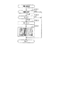
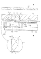
(第1の実施形態)
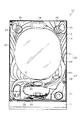
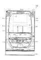
以下、遊技機の一種であるパチンコ遊技機(以下、「パチンコ機」という)の第1の実施形態を、図面に基づいて詳細に説明する。図1はパチンコ機10の正面図、図2及び図3はパチンコ機10の主要な構成を展開して示す斜視図、図4はパチンコ機10の背面図である。なお、図2では便宜上パチンコ機10の遊技領域内の構成を省略している。なお、図3や図4等においては、便宜上、各機器を相互に電気的に接続するためのハーネスなどといった電気配線を省略して示す。
(First embodiment)
Hereinafter, a first embodiment of a pachinko gaming machine (hereinafter referred to as “pachinko machine”), which is a type of gaming machine, will be described in detail with reference to the drawings. FIG. 1 is a front view of the pachinko machine 10, FIGS. 2 and 3 are perspective views showing the main configuration of the pachinko machine 10, and FIG. 4 is a rear view of the pachinko machine 10. FIG. In FIG. 2, the configuration in the game area of the pachinko machine 10 is omitted for convenience. In FIG. 3 and FIG. 4 and the like, for the sake of convenience, electric wiring such as a harness for electrically connecting the devices to each other is omitted.

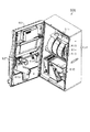
パチンコ機10は、当該パチンコ機10の外殻を形成する外枠11と、この外枠11に対して前方に回動可能に取り付けられた遊技機主部12とを有する。外枠11は木製の板材を四辺に連結し構成されるものであって矩形枠状をなしている。パチンコ機10は、外枠11を島設備に取り付け固定することにより、遊技ホールに設置される。   The pachinko machine 10 includes an outer frame 11 that forms an outer shell of the pachinko machine 10, and a gaming machine main part 12 that is rotatably attached to the outer frame 11. The outer frame 11 is configured by connecting wooden plates to four sides and has a rectangular frame shape. The pachinko machine 10 is installed in the game hall by attaching and fixing the outer frame 11 to the island facility.

遊技機主部12は、ベース体としての本体枠13と、その本体枠13の前方に配置される前扉枠14と、本体枠13の後方に配置される裏パックユニット15とを備えている。遊技機主部12のうち本体枠13が外枠11に対して回動可能に支持されている。詳細には、正面視で左側を回動基端側(開閉基端側)とし右側を回動先端側(開閉先端側)として本体枠13が前方へ回動可能とされている。   The gaming machine main part 12 includes a main body frame 13 as a base body, a front door frame 14 disposed in front of the main body frame 13, and a back pack unit 15 disposed behind the main body frame 13. . The main body frame 13 of the gaming machine main part 12 is supported so as to be rotatable with respect to the outer frame 11. Specifically, the main body frame 13 can be rotated forward with the left side in the front view as the rotation base end side (opening / closing base end side) and the right side as the rotation front end side (opening / closing front end side).

本体枠13には、図2に示すように、前扉枠14が回動可能に支持されており、正面視で左側を回動基端側(開閉基端側)とし右側を回動先端側(開閉先端側)として前方へ回動可能とされている。また、本体枠13には、図3に示すように、裏パックユニット15が回動可能に支持されており、正面視で左側を回動基端側(開閉基端側)とし右側を回動先端側(開閉先端側)として後方へ回動可能とされている。   As shown in FIG. 2, a front door frame 14 is rotatably supported on the main body frame 13, and the left side is a rotation base end side (opening / closing base end side) and the right side is a rotation front end side in a front view. It can be rotated forward as (opening / closing tip side). Further, as shown in FIG. 3, the backpack unit 15 is rotatably supported by the main body frame 13, and in the front view, the left side is the rotation base end side (opening / closing base end side), and the right side is rotated. It is possible to turn rearward as the front end side (opening / closing front end side).

次に、前扉枠14について説明する。なお、以下の説明では、図1〜図3を参照するとともに、前扉枠14の背面の構成については図5を参照する。図5は、前扉枠14の背面図である。   Next, the front door frame 14 will be described. In the following description, FIGS. 1 to 3 are referred to, and FIG. 5 is referred to for the configuration of the back surface of the front door frame 14. FIG. 5 is a rear view of the front door frame 14.

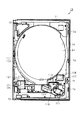
前扉枠14は本体枠13の前面側全体を覆うようにして設けられている。前扉枠14には後述する遊技領域のほぼ全域を前方から視認することができるように遊技領域用窓部20が設けられている。遊技領域用窓部20は、前扉枠14に形成された略円形状の窓枠部21に、透明性を有する具体的には無色透明のガラス22を嵌め込むことで構成されている。なお、遊技領域用窓部20は、遊技領域を前方から視認可能とする機能を有しているのであれば、その構成は任意であり、例えば、ガラス22に代えて、透明性を有する具体的には無色透明の合成樹脂により形成された透明樹脂板を設けてもよい。   The front door frame 14 is provided so as to cover the entire front side of the main body frame 13. The front door frame 14 is provided with a game area window 20 so that almost the entire game area, which will be described later, can be viewed from the front. The game area window portion 20 is configured by fitting a transparent, specifically, colorless and transparent glass 22 into a substantially circular window frame portion 21 formed in the front door frame 14. The game area window 20 may have any configuration as long as the game area has a function of making the game area visible from the front. May be provided with a transparent resin plate formed of a colorless and transparent synthetic resin.

窓枠部21の周囲には、各種ランプ等の発光手段が設けられている。例えば、窓枠部21の周縁に沿ってLED等の発光手段を内蔵した環状電飾部23が設けられている。環状電飾部23では、大当たり時や所定のリーチ時等における遊技状態の変化に応じて点灯や点滅が行われる。また、環状電飾部23の中央であってパチンコ機10の最上部には所定のエラー時に点灯するエラー表示ランプ部24が設けられ、さらにその左右側方には賞球払出中に点灯する賞球ランプ部25が設けられている。また、左右の賞球ランプ部25に近接した位置には、遊技状態に応じた効果音などが出力されるスピーカ部26が設けられている。   Around the window frame portion 21, light emitting means such as various lamps are provided. For example, an annular illumination part 23 containing a light emitting means such as an LED is provided along the periphery of the window frame part 21. In the annular illumination part 23, lighting or blinking is performed in accordance with a change in the gaming state at the time of a big hit or a predetermined reach. In addition, an error display lamp unit 24 that is turned on at the time of a predetermined error is provided at the center of the annular illumination unit 23 and at the uppermost part of the pachinko machine 10, and a prize that is turned on while the prize ball is being paid out on the left and right sides. A ball lamp portion 25 is provided. In addition, a speaker unit 26 is provided at a position close to the left and right prize ball lamp units 25 to output a sound effect corresponding to the gaming state.

前扉枠14における窓枠部21の下方には、手前側へ膨出した上側膨出部31と下側膨出部32とが上下に並設されている。上側膨出部31内側には上方に開口した上皿33が設けられており、下側膨出部32内側には同じく上方に開口した下皿34が設けられている。上皿33は、後述する払出装置より払い出された遊技球を一旦貯留し、一列に整列させながら後述する遊技球発射機構側へ導くための機能を有する。また、下皿34は、上皿33内にて余剰となった遊技球を貯留する機能を有する。   Below the window frame portion 21 in the front door frame 14, an upper bulging portion 31 and a lower bulging portion 32 that bulge toward the front side are arranged side by side. An upper pan 33 that opens upward is provided inside the upper bulging portion 31, and a lower pan 34 that also opens upward is provided inside the lower bulging portion 32. The upper plate 33 has a function of temporarily storing game balls paid out from a payout device described later and guiding them to the game ball launching mechanism described later while aligning them in a line. In addition, the lower tray 34 has a function of storing game balls that become surplus in the upper tray 33.

下側膨出部32の右方には、手前側へ突出するようにして遊技球発射ハンドル41が設けられている。遊技球発射ハンドル41が操作されることにより、後述する遊技球発射機構から遊技球が発射される。   A game ball launching handle 41 is provided on the right side of the lower bulging portion 32 so as to protrude toward the front side. By operating the game ball launch handle 41, a game ball is launched from a game ball launch mechanism described later.

前扉枠14の背面には、図2及び図5に示すように、通路形成ユニット50が取り付けられている。通路形成ユニット50は、合成樹脂により形成されており、上皿33に通じる前扉側上皿通路51と、下皿34に通じる前扉側下皿通路52とが形成されている。通路形成ユニット50において、その上側隅部には後方に突出し上方に開放された受口部53が形成されており、当該受口部53を仕切壁54によって左右に仕切ることで前扉側上皿通路51と前扉側下皿通路52の入口部分とが形成されている。前扉側上皿通路51及び前扉側下皿通路52は上流側が後述する遊技球分配部に通じており、前扉側上皿通路51に入った遊技球は上皿33に導かれ、前扉側下皿通路52に入った遊技球は下皿34に導かれる。   As shown in FIGS. 2 and 5, a passage forming unit 50 is attached to the back surface of the front door frame 14. The passage forming unit 50 is formed of a synthetic resin, and includes a front door side upper dish passage 51 that communicates with the upper dish 33 and a front door side lower dish passage 52 that communicates with the lower dish 34. In the passage forming unit 50, a receiving portion 53 that protrudes rearward and opens upward is formed at an upper corner portion thereof, and the receiving portion 53 is divided into left and right portions by a partition wall 54, whereby the front door side upper plate is formed. A passage 51 and an entrance portion of the front door side lower dish passage 52 are formed. The upstream side of the front door side upper dish passage 51 and the front door side lower dish path 52 are connected to a game ball distributing section described later, and the game balls that have entered the front door side upper dish path 51 are guided to the upper plate 33, The game balls that have entered the door-side lower dish passage 52 are guided to the lower dish 34.

前扉枠14の背面における回動基端側(図5の右側)には、その上端部及び下端部に突起軸61,62が設けられている。これら突起軸61,62は本体枠13に対する組付機構を構成する。また、前扉枠14の背面における回動先端側(図5の左側)には、図2に示すように、後方に延びる鉤金具63が上下方向に複数並設されている。これら鉤金具63は本体枠13に対する施錠機構を構成する。   Protrusion shafts 61 and 62 are provided on the upper and lower ends of the rotation base end side (the right side in FIG. 5) on the back surface of the front door frame 14. These projecting shafts 61 and 62 constitute an assembly mechanism for the main body frame 13. Further, as shown in FIG. 2, a plurality of hook metal fittings 63 extending rearward are arranged in the vertical direction on the rotating front end side (left side in FIG. 5) on the back surface of the front door frame 14. These hooks 63 constitute a locking mechanism for the main body frame 13.

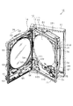
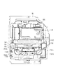
次に、本体枠13について詳細に説明する。図6は本体枠13の正面図である。   Next, the main body frame 13 will be described in detail. FIG. 6 is a front view of the main body frame 13.

本体枠13は、外形が外枠11とほぼ同一形状をなす樹脂ベース71を主体に構成されている。樹脂ベース71の前面における回動基端側(図6の左側)には、その上端部及び下端部に支持金具72,73が取り付けられている。図示は省略するが、支持金具72,73には軸孔が形成されており、それら軸孔に前扉枠14の突起軸61,62が挿入されることにより、本体枠13に対して前扉枠14が回動可能に支持されている。   The main body frame 13 is mainly composed of a resin base 71 whose outer shape is substantially the same as that of the outer frame 11. Support metal fittings 72 and 73 are attached to an upper end portion and a lower end portion of the rotation base end side (left side in FIG. 6) on the front surface of the resin base 71. Although illustration is omitted, shaft holes are formed in the support fittings 72 and 73, and the projecting shafts 61 and 62 of the front door frame 14 are inserted into these shaft holes, so that the front door with respect to the main body frame 13. The frame 14 is rotatably supported.

樹脂ベース71の前面における回動先端側(図6の右側)には、前扉枠14の背面に設けられた鉤金具63を挿入するための挿入孔74がそれぞれ設けられている。本パチンコ機10では、本体枠13や前扉枠14を施錠状態とするための施錠装置が本体枠13の背面側に隠れて配置される構成となっている。したがって、鉤金具63が挿入孔74を介して施錠装置に係止されることによって、前扉枠14が本体枠13に対して開放不能に施錠される。   Insertion holes 74 for inserting the metal fittings 63 provided on the back surface of the front door frame 14 are provided on the rotation front end side (right side in FIG. 6) on the front surface of the resin base 71. The pachinko machine 10 is configured such that a locking device for locking the main body frame 13 and the front door frame 14 is hidden behind the main body frame 13. Accordingly, the front door frame 14 is locked to the main body frame 13 so as not to be opened by the hook metal 63 being locked to the locking device via the insertion hole 74.

樹脂ベース71の右下隅部には、施錠装置の解錠操作を行うためのシリンダ錠75が設置されている。シリンダ錠75は施錠装置に一体化されており、シリンダ錠75の鍵穴に差し込んだキーを右に回すと本体枠13に対する前扉枠14の施錠が解かれるようになっている。なお、シリンダ錠75の鍵穴に差し込んだキーを左に回すと外枠11に対する本体枠13の施錠が解かれるようになっている。   A cylinder lock 75 for performing an unlocking operation of the locking device is installed at the lower right corner of the resin base 71. The cylinder lock 75 is integrated with the locking device. When the key inserted into the key hole of the cylinder lock 75 is turned to the right, the front door frame 14 is unlocked with respect to the main body frame 13. When the key inserted into the key hole of the cylinder lock 75 is turned counterclockwise, the lock of the main body frame 13 with respect to the outer frame 11 is released.

樹脂ベース71の中央部には略楕円形状の窓孔76が形成されている。樹脂ベース71には遊技盤81が着脱可能に取り付けられている。遊技盤81は合板よりなり、遊技盤81の前面に形成された遊技領域が樹脂ベース71の窓孔76を通じて本体枠13の前面側に露出した状態となっている。   A substantially elliptical window hole 76 is formed at the center of the resin base 71. A game board 81 is detachably attached to the resin base 71. The game board 81 is made of plywood, and the game area formed on the front surface of the game board 81 is exposed to the front surface side of the main body frame 13 through the window hole 76 of the resin base 71.

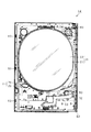
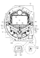
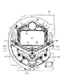
遊技盤81の構成を図7に基づいて説明する。   The configuration of the game board 81 will be described with reference to FIG.

遊技盤81には、遊技領域を区画するように、内レール部101と外レール部102とが取り付けられており、これら内レール部101と外レール部102とにより誘導レールが構成されている。後述する遊技球発射機構から発射された遊技球が遊技領域の上部に案内されるようになっている。   An inner rail portion 101 and an outer rail portion 102 are attached to the game board 81 so as to divide a game area, and the inner rail portion 101 and the outer rail portion 102 constitute a guide rail. A game ball launched from a later-described game ball launching mechanism is guided to the upper part of the game area.

遊技盤81には、ルータ加工が施されることによって前後方向に貫通する大小複数の開口部が形成されている。各開口部には一般入賞口82,可変入賞装置83,作動口84,スルーゲート85及び可変表示ユニット86等がそれぞれ設けられている。一般入賞口82は、左右にそれぞれ2個ずつ合計4個設けられている。一般入賞口82、可変入賞装置83及び作動口84に遊技球が入ると、それが後述する検知スイッチにより検知され、その検知結果に基づいて所定数の賞球の払い出しが実行される。   The game board 81 has a plurality of large and small openings penetrating in the front-rear direction by being subjected to router processing. Each opening is provided with a general winning port 82, a variable winning device 83, an operating port 84, a through gate 85, a variable display unit 86, and the like. A total of four general winning ports 82 are provided on the left and right. When a game ball enters the general winning port 82, the variable winning device 83, and the operation port 84, it is detected by a detection switch described later, and a predetermined number of award balls are paid out based on the detection result.

ここで、遊技盤81には、その左右の下部に装飾部材89a,89bが設けられている。これら装飾部材89a,89bは、内レール101に沿うようにして設けられており、遊技盤81の表面よりも前方に張り出している。この張り出す量は、装飾部材89a,89bとガラス22との間の距離が遊技球1個分未満となる程度となっている。上記一般入賞口82は、装飾部材89a,89bに対して設けられている。   Here, the game board 81 is provided with decorative members 89a and 89b at the left and right lower portions thereof. These decorative members 89 a and 89 b are provided along the inner rail 101 and project forward from the surface of the game board 81. The protruding amount is such that the distance between the decorative members 89a and 89b and the glass 22 is less than one game ball. The general winning opening 82 is provided for the decorative members 89a and 89b.

可変表示ユニット86には、作動口84への入賞をトリガとして図柄を可変表示する図柄表示装置91が設けられている。また、可変表示ユニット86には、図柄表示装置91を囲むようにしてセンターフレーム92が配設されている。   The variable display unit 86 is provided with a symbol display device 91 for variably displaying symbols with a winning at the operation port 84 as a trigger. The variable display unit 86 is provided with a center frame 92 so as to surround the symbol display device 91.

図柄表示装置91は、液晶ディスプレイを備えた液晶表示装置として構成されており、後述する表示制御装置により表示内容が制御される。図柄表示装置91には、例えば左、中及び右に並べて図柄が表示され、これらの図柄が上下方向にスクロールされるようにして変動表示されるようになっている。そして、予め設定されている有効ライン上に所定の組合せの図柄が停止表示された場合には、特別遊技状態(以下、大当たりという)が発生することとなる。   The symbol display device 91 is configured as a liquid crystal display device including a liquid crystal display, and display contents are controlled by a display control device described later. On the symbol display device 91, for example, symbols are displayed side by side on the left, middle, and right, and these symbols are variably displayed as they are scrolled up and down. When a predetermined combination of symbols is stopped and displayed on a preset active line, a special gaming state (hereinafter referred to as a jackpot) occurs.

可変入賞装置83は、入球口を備えているとともに、当該入球口を開閉する扉体83aを備えている。そして、扉体83aは、通常は遊技球が入賞できない又は入賞しがたい閉鎖状態になっており、大当たりの際に遊技球が入賞しやすい所定の開放状態に切り換えられるようになっている。なお、この入賞しやすい所定の開放状態とは、遊技領域を流下する遊技球を扉体83a自身によって入球口に向けてガイドする状態のことを言う。   The variable winning device 83 includes a ball entrance and a door 83a that opens and closes the ball entrance. The door 83a is normally in a closed state in which a game ball cannot be won or is difficult to win, and is switched to a predetermined open state in which a game ball is easy to win in a big hit. Note that the predetermined open state that is easy to win means a state in which the game ball flowing down the game area is guided toward the entrance by the door body 83a itself.

可変入賞装置83の開放態様としては、所定時間(例えば30秒間)の経過又は所定個数(例えば10個)の入賞を1ラウンドとして、規定回数のラウンドを上限として可変入賞装置83が繰り返し開放される。この場合、本パチンコ機10では、大当たり時に設定されるラウンドの規定回数の態様が、複数パターン設けられている。具体的には、第1規定回数(例えば、2回)のラウンドが設定される第1大当たりと、第1規定回数よりも多い回数である第2規定回数(例えば、15回)のラウンドが設定される第2大当たりとが設けられている。これにより、大当たり時の態様の多様化が図られている。   As an opening mode of the variable winning device 83, the variable winning device 83 is repeatedly opened with a predetermined time (for example, 30 seconds) or a predetermined number (for example, 10) of winnings as one round and a predetermined number of rounds as an upper limit. . In this case, the pachinko machine 10 is provided with a plurality of patterns of the prescribed number of rounds set at the time of the big hit. Specifically, a first big hit in which a first specified number of rounds (for example, 2 times) is set and a second specified number of rounds (for example, 15 times) that are more than the first specified number of rounds are set. And a second jackpot is provided. Thereby, diversification of the mode of the big hit is achieved.

その他に、遊技盤81の最下部にはアウト口87が設けられており、各種入賞口等に入らなかった遊技球はアウト口87を通って遊技領域から排出される。また、遊技盤81には、遊技球の落下方向を適宜分散、調整等するために多数の釘88が植設されていると共に、風車等の各種部材(役物)が配設されている。   In addition, an out port 87 is provided at the lowermost part of the game board 81, and game balls that have not entered various winning ports etc. are discharged from the game area through the out port 87. The game board 81 is provided with a large number of nails 88 in order to appropriately disperse and adjust the falling direction of the game ball, and various members (instruments) such as a windmill.

遊技盤81には、特定報知領域93が設けられている。特定報知領域93は、遊技盤81において上記ガラス22を通じて視認可能な領域(又は遊技領域内)であって遊技球が流下しない領域に設けられている。具体的には、特定報知領域93は、右側の装飾部材89bによって区画され、当該装飾部材89bによって遊技球の流入が阻止された領域に設けられている。   The game board 81 is provided with a specific notification area 93. The specific notification area 93 is provided in an area where the game board 81 can be visually recognized through the glass 22 (or in the game area) and where the game ball does not flow down. Specifically, the specific notification area 93 is defined by a right decoration member 89b, and is provided in an area where the inflow of game balls is blocked by the decoration member 89b.

特定報知領域93には、第1特定発光部94と、第2特定発光部95と、第3特定発光部96とが設けられており、各特定発光部94,95,96に対してはそれぞれ異なる光源からの光が照射され、各特定発光部94,95,96を透過する光によりそれぞれ個別に遊技状況の報知が行われる。各特定発光部94〜96は、無色透明のガラスや合成樹脂により形成されており、遊技盤81を前後方向に貫通させて設けられている。この場合、特定発光部94〜96と、遊技盤81との間に隙間は存在していない。また、各特定発光部94〜96は前面と後面とが共に平面であり、それら前面及び後面は共に遊技盤81の盤面に対して平行又は略平行となっている。   The specific notification area 93 is provided with a first specific light emitting unit 94, a second specific light emitting unit 95, and a third specific light emitting unit 96, and for each specific light emitting unit 94, 95, 96, respectively. Light from different light sources is irradiated, and the game situation is individually notified by the light transmitted through the specific light emitting units 94, 95, and 96. Each of the specific light emitting portions 94 to 96 is made of colorless and transparent glass or synthetic resin, and is provided by penetrating the game board 81 in the front-rear direction. In this case, there is no gap between the specific light emitting units 94 to 96 and the game board 81. Each of the specific light emitting units 94 to 96 has a flat front surface and a rear surface, and both the front surface and the rear surface are parallel to or substantially parallel to the surface of the game board 81.

第1特定発光部94では、各遊技回において大当たりの発生の有無が報知される。つまり、第1特定発光部94では、作動口84への入賞をトリガとして所定の順序で発光色の切り替えが行われ、予め定められた色で停止表示された場合には大当たりが発生する。   In the 1st specific light emission part 94, the presence or absence of generation | occurrence | production of jackpot in each game time is alert | reported. In other words, in the first specific light emitting unit 94, the emission color is switched in a predetermined order with a winning at the operation port 84 as a trigger, and when the display is stopped in a predetermined color, a big hit occurs.

具体的には、赤色→緑色→青色→赤色→緑色→・・・の順序で発光色の切り替えが行われ、大当たりが発生しない場合には青色が停止表示される。また、大当たりが発生する場合には赤色又は緑色が停止表示される。この場合、大当たり終了後に大当たり確率が上昇する確変大当たりが発生する場合には赤色が停止表示され、確変大当たりではない通常大当たりが発生する場合には緑色が停止表示される。また、これら停止表示された状態は、次回の発光色の切り替えが開始されるまで維持される。したがって、大当たり中においても停止表示が継続されるとともに、遊技が行われていない状況においても停止表示が継続される。さらには、パチンコ機10の電源がONとなった際には、前回電源がOFFとなった際に停止表示されていた色の表示が再開される。なお、上記停止表示される色の態様は任意であり、さらにまた大当たりの発生時には赤色又は緑色を停止表示するが大当たりの開始後には青色を停止表示する態様としてもよい。   Specifically, the emission color is switched in the order of red → green → blue → red → green →..., And blue is stopped and displayed when no big hit occurs. When a big hit occurs, red or green is stopped and displayed. In this case, if a probable jackpot that increases the probability of jackpot after the jackpot ends, red is stopped and displayed, and if a normal jackpot that is not a probable jackpot occurs, green is stopped and displayed. Further, the stopped display state is maintained until the next switching of the emission color is started. Therefore, the stop display is continued even during the big hit, and the stop display is continued even in a situation where no game is played. Furthermore, when the power of the pachinko machine 10 is turned on, the display of the color that was stopped and displayed when the power was last turned off is resumed. The color of the stop-displayed color is arbitrary. Furthermore, red or green is stopped and displayed when the jackpot is generated, but blue may be stopped and displayed after the jackpot is started.

ここで、上記のとおり、図柄表示装置91において予め設定されている有効ライン上に所定の組合せの図柄が停止表示された場合にも、大当たりが発生する。つまり、大当たりが発生する場合には、第1特定発光部94における発光色の切り替えが予め定められた色で停止表示されるとともに、図柄表示装置91において所定の組合せの図柄が停止表示される。   Here, as described above, even when a predetermined combination of symbols is stopped and displayed on the active line set in advance in the symbol display device 91, a big hit occurs. That is, when a big hit occurs, the switching of the emission color in the first specific light emitting unit 94 is stopped and displayed in a predetermined color, and a predetermined combination of symbols is stopped and displayed on the symbol display device 91.

ちなみに、センターフレーム91の下部には、保留発光部98が設けられており、遊技球が作動口84を通過した回数は最大4回まで保留され保留発光部98の点灯によってその保留個数が表示されるようになっている。なお、保留回数の上限は4回に限定されることはなく、4回未満であっても5回以上であってもよい。また、作動口84が複数設けられた構成においては、第1作動口用の保留発光部と第2作動口用の保留発光部とをそれぞれ備えた構成としてもよい。   Incidentally, a holding light emitting unit 98 is provided at the lower part of the center frame 91, and the number of times that the game ball has passed through the operation port 84 is held up to 4 times, and the number of holdings is displayed by lighting the holding light emitting unit 98. It has become so. In addition, the upper limit of the number of times of holding is not limited to four times, and may be less than four times or five times or more. Further, in the configuration in which a plurality of operation ports 84 are provided, a configuration may be provided in which a holding light emitting unit for the first working port and a holding light emitting unit for the second operation port are provided.

第2特定発光部95では、大当たりが発生した際に、ラウンドの規定回数がいずれのパターンかが報知される。つまり、図柄表示装置91において大当たりの発生に対応した所定の組合せの図柄が停止表示されたタイミング又は第1特定発光部94において大当たりの発生に対応した予め定められた色が停止表示されたタイミングに対応させて、第1規定回数の大当たりが発生するか第2規定回数の大当たりが発生するかが報知される。   In the second specific light emitting unit 95, when a jackpot is generated, it is notified which pattern the prescribed number of rounds has. That is, at a timing at which a predetermined combination of symbols corresponding to the occurrence of the jackpot is stopped on the symbol display device 91 or at a timing at which a predetermined color corresponding to the occurrence of the jackpot is stopped and displayed at the first specific light emitting unit 94. Correspondingly, it is notified whether the first specified number of jackpots or the second specified number of jackpots occurs.

具体的には、第1規定回数の大当たりが発生する場合には青色が表示され、第2規定回数の大当たりが発生する場合には赤色が表示される。これら表示された状態は、次回の大当たりが発生するまで維持される。したがって、大当たり中においても表示が継続されるとともに、遊技が行われていない状況においても表示が継続される。さらには、パチンコ機10の電源がONとなった際には、前回電源がOFFとなった際に表示されていた色の表示が再開される。なお、上記表示される色の態様は任意であり、また第2規定回数の大当たりの発生時に赤色を表示するが大当たりの開始後には青色を表示する態様としてもよい。また、大当たり中でない状況では、第2特定発光部95において大当たり中とは異なる表示を行うようにしてもよい。   Specifically, blue is displayed when the first specified number of jackpots occurs, and red is displayed when the second specified number of jackpots occurs. These displayed states are maintained until the next jackpot occurs. Therefore, the display is continued even during the jackpot, and the display is continued even in a situation where no game is played. Furthermore, when the power of the pachinko machine 10 is turned on, the display of the color displayed when the power was turned off last time is resumed. In addition, the mode of the displayed color is arbitrary, and red may be displayed when the second specified number of jackpots is generated, but blue may be displayed after the jackpot is started. In a situation where the jackpot is not being hit, the second specific light emitting unit 95 may perform a display different from that for the jackpot.

第3特定発光部96では、作動口84に付随する電動役物84aを開放状態とするか否かの報知が行われる。つまり、第3特定発光部96では、遊技球のスルーゲート85の通過をトリガとして所定の順序で発光色の切り替えが行われ、予め定められた色で停止表示された場合には電動役物84aが所定時間だけ開放状態となる。なお、電動役物84aが開放状態となることで、遊技領域を流下する遊技球が当該電動役物84a自身によって作動口84に向けてガイドされ、作動口84への入球が発生し易くなる。   In the 3rd specific light emission part 96, the alerting | reporting of whether the electrically-driven accessory 84a accompanying the operation port 84 is made into an open state is performed. That is, in the third specific light emitting unit 96, the light emission color is switched in a predetermined order triggered by the passage of the game ball through the through gate 85, and when the display is stopped in a predetermined color, the electric accessory 84a Is opened for a predetermined time. In addition, when the electric accessory 84a is in the open state, the game ball flowing down the game area is guided toward the operation port 84 by the electric accessory 84a itself, and it is easy for the ball to enter the operation port 84 to occur. .

具体的には、赤色→緑色→赤色→・・・の順序で発光色の切り替えが行われ、電動役物84aを開放状態としない場合には緑色が停止表示され、電動役物84aを開放状態とする場合には赤色が停止表示される。また、これら停止表示された状態は、次回の発光色の切り替えが開始されるまで維持される。したがって、電動役物84aの開放状態中においても停止表示が継続されるとともに、遊技が行われていない状況においても停止表示が継続される。さらには、パチンコ機10の電源がONとなった際には、前回電源がOFFとなった際に停止表示されていた色の表示が再開される。なお、上記表示される色の態様は任意であり、また電動役物84aの開放開始時には赤色を停止表示するが電動役物84aの開放中には緑色を停止表示する態様としてもよい。   Specifically, the light emission color is switched in the order of red → green → red →..., Green is stopped when the electric accessory 84a is not opened, and the electric accessory 84a is opened. In this case, red is stopped and displayed. Further, the stopped display state is maintained until the next switching of the emission color is started. Therefore, the stop display is continued even when the electric accessory 84a is in the open state, and the stop display is continued even in a situation where no game is played. Furthermore, when the power of the pachinko machine 10 is turned on, the display of the color that was stopped and displayed when the power was last turned off is resumed. The display mode of the color is arbitrary, and red is stopped when the opening of the electric accessory 84a is started. However, green may be stopped and displayed while the electric accessory 84a is opened.

ちなみに、センターフレーム91の上部には、保留発光部99が設けられており、遊技球がスルーゲート85を通過した回数は最大4回まで保留され保留発光部99の点灯によってその保留個数が表示されるようになっている。なお、保留個数の上限は4回に限定されることはなく、4回未満であっても5回以上であってもよい。   Incidentally, a holding light emitting unit 99 is provided at the upper part of the center frame 91, and the number of times that the game ball has passed through the through gate 85 is held up to 4 times, and the number of holdings is displayed by lighting the holding light emitting unit 99. It has become so. In addition, the upper limit of the number of reservations is not limited to 4 times, and may be less than 4 times or 5 times or more.

遊技盤81には、証紙透過部104が設けられている。証紙透過部104は、遊技盤81において上記遊技領域用窓部20を通じて視認可能な領域であって遊技球が流下しない領域に設けられている。具体的には、証紙透過部104は、右側の装飾部材89bによって区画され、当該装飾部材89bによって遊技球の流入が阻止された領域に設けられている。また、証紙透過部104は、上記特定報知領域93と並設されている。具体的には、証紙透過部104は、特定報知領域93と上下に並設されている。なお、証紙透過部104を、特定報知領域93と左右に並設してもよい。   The game board 81 is provided with a certificate paper transmitting portion 104. The certificate paper transmitting portion 104 is provided in an area that is visible through the game area window section 20 on the game board 81 and that does not allow game balls to flow down. Specifically, the certificate paper transmitting portion 104 is defined by a right decoration member 89b, and is provided in a region where the inflow of game balls is blocked by the decoration member 89b. Further, the certificate paper transmitting portion 104 is arranged in parallel with the specific notification area 93. Specifically, the certificate paper transmitting portion 104 is arranged in parallel with the specific notification area 93. Note that the certificate paper transmitting portion 104 may be arranged side by side with the specific notification area 93.

証紙透過部104は、無色透明のガラスや合成樹脂により形成されており、遊技盤81を前後方向に貫通させて設けられている。この場合、証紙透過部104と遊技盤81との間に隙間は介在していない。証紙透過部104は、後述する主制御装置162に設けられた基板用証紙197をパチンコ機10前方から視認可能とするための機能を有する。つまり、証紙透過部104の後方には基板用証紙197が位置しており、さらに証紙透過部104はパチンコ機10前方から上記ガラス22及び証紙透過部104を通じて基板用証紙197を視認可能な程度の透明性を有している。これにより、パチンコ機10前方からガラス22及び証紙透過部104を通じて基板用証紙197が視認可能となっている。なお、基板用証紙197の詳細については後に説明する。   The certificate paper transmitting portion 104 is made of colorless and transparent glass or synthetic resin, and is provided by penetrating the game board 81 in the front-rear direction. In this case, there is no gap between the certificate paper transmitting portion 104 and the game board 81. The certificate paper transmitting unit 104 has a function for making it possible to visually recognize the substrate certificate paper 197 provided in the main controller 162 described later from the front of the pachinko machine 10. That is, the board certificate paper 197 is positioned behind the certificate paper transmission part 104, and the certificate paper transmission part 104 is visible to the board certificate paper 197 through the glass 22 and the certificate paper transmission part 104 from the front of the pachinko machine 10. It has transparency. Thereby, the board certificate 197 is visible from the front of the pachinko machine 10 through the glass 22 and the certificate transmission part 104. The details of the board certificate 197 will be described later.

遊技盤81の右下隅部には、証紙貼付部106が設けられている。証紙貼付部106は証紙透過部104に対して並設されている。具体的には、証紙貼付部106は証紙透過部104に対して上下に並設されている。なお、証紙貼付部106を証紙透過部104に対して左右に並設してもよい。証紙貼付部106は箱状をなしており、その表面が遊技盤81の表面よりもパチンコ機10前方に張り出している。証紙貼付部106の表面には、盤用証紙107が貼り付けられている。   In the lower right corner of the game board 81, a certificate sticking unit 106 is provided. The certificate sticking unit 106 is arranged in parallel with the certificate paper transmitting unit 104. Specifically, the certificate sticking unit 106 is arranged in parallel above and below the certificate paper transmitting unit 104. Note that the certificate sticking unit 106 may be provided side by side with respect to the certificate sheet transmitting unit 104. The stamp sticking portion 106 has a box shape, and the surface of the stamp sticking portion 106 protrudes ahead of the pachinko machine 10 from the surface of the game board 81. A board certificate 107 is affixed to the surface of the certificate affixing section 106.

盤用証紙107は、その表面にパチンコ機10の機種名(具体的には、「○○物語」)及び型式名(具体的には、「M―1」)が記されている。ここで、「機種名」とは、パチンコ機10の種類を特定するための情報のことをいい、異なる機種同士では遊技内容及び外観等が異なっている。この遊技内容には、図柄表示装置91における図柄の種類や図柄の変動パターンが含まれ、また大当たり状態の種類や大当たり状態における出球数等が含まれる。また、「型式名」とは、同一機種間におけるパチンコ機10の型式を特定するための情報のことをいい、同一機種間において異なる型式同士では、外観や図柄表示装置91における図柄の種類などは同一であるものの、大当たり状態の発生確率等が異なっている。なお、盤用証紙107に、上記機種名及び型式名に加えて、パチンコ機10の製造メーカ名、パチンコ機10の製造番号又は遊技盤81の製造番号などを記すようにしてもよい。   The board certificate 107 has a model name (specifically “OO story”) and a model name (specifically “M-1”) of the pachinko machine 10 on the surface. Here, the “model name” refers to information for specifying the type of the pachinko machine 10, and the game content and appearance differ between different models. This game content includes the type of symbol and the symbol variation pattern in the symbol display device 91, and also includes the type of jackpot state and the number of balls in the jackpot state. Further, the “model name” refers to information for specifying the model of the pachinko machine 10 between the same models. In the models that are different between the same models, the appearance, the type of symbols in the symbol display device 91, and the like are as follows. Although they are the same, the probability of occurrence of a jackpot state is different. In addition to the model name and model name, the manufacturer name of the pachinko machine 10, the manufacturing number of the pachinko machine 10, or the manufacturing number of the game board 81 may be written on the board certificate 107.

盤用証紙107における表示内容は、前扉枠14に形成された証紙用窓部27を通じて視認可能となっている。詳細には、前扉枠14には、図1に示すように、遊技領域用窓部20に隣接させて証紙用窓部27が形成されている。証紙用窓部27は、前扉枠14に形成された楕円形状の窓枠部28に、透明性を有する具体的には無色透明のガラス29を嵌め込むことで構成されている。なお、証紙用窓部27は、盤用証紙107をパチンコ機10前方から視認可能とする機能を有しているのであれば、その構成は任意であり、例えば、ガラス29に代えて、透明性を有する具体的には無色透明の合成樹脂により形成された透明樹脂板を設けてもよい。また、証紙用窓部27を設けずに、代わりに、遊技領域用窓部20を通じて盤用証紙107を視認可能とする構成としてもよい。   The display content on the board certificate 107 is visible through the certificate window 27 formed on the front door frame 14. Specifically, as shown in FIG. 1, the front door frame 14 is formed with a certificate window 27 adjacent to the game area window 20. The certificate window portion 27 is configured by fitting a transparent, specifically, colorless and transparent glass 29 into an elliptical window frame portion 28 formed on the front door frame 14. The certificate window portion 27 may have any configuration as long as it has a function of making the board certificate 107 visible from the front of the pachinko machine 10. For example, the certificate window portion 27 may be transparent instead of the glass 29. Specifically, a transparent resin plate formed of a colorless and transparent synthetic resin may be provided. Instead of providing the certificate window 27, the board certificate 107 may be visible through the game area window 20 instead.

遊技盤81の下方には、遊技球発射機構110が設けられている。遊技球発射機構110は、図6に示すように、樹脂ベース71における窓孔76の下方に取り付けられている。遊技球発射機構110は、電磁式のソレノイド111と、発射レール112と、球送り機構113とからなり、ソレノイド111への電気的な信号の入力により当該ソレノイド111の出力軸が伸縮方向に移動し、球送り機構113によって発射レール112上に置かれた遊技球を遊技領域に向けて打ち出す。   Below the game board 81, a game ball launching mechanism 110 is provided. The game ball launching mechanism 110 is attached below the window hole 76 in the resin base 71 as shown in FIG. The game ball launch mechanism 110 includes an electromagnetic solenoid 111, a launch rail 112, and a ball feed mechanism 113, and the output shaft of the solenoid 111 moves in the expansion / contraction direction by the input of an electrical signal to the solenoid 111. Then, the game ball placed on the firing rail 112 is launched toward the game area by the ball feeding mechanism 113.

発射レール112と遊技盤81に取り付けられた内,外レール部101,102との間には所定間隔の隙間があり、この隙間より下方には前扉枠14の通路形成ユニット50に形成されたファール球通路55が配設されている(図5参照)。したがって、仮に遊技球発射機構110から発射された遊技球が遊技領域の上部に到達せずに、内,外レール部101,102によって構成される誘導レールを逆戻りする場合には、そのファール球がファール球通路55内に入る。ファール球通路55は前扉側下皿通路52に通じており、ファール球通路55に入った遊技球は下皿34に排出される。   There is a gap of a predetermined interval between the inner rail rails 101 and 102 attached to the launch rail 112 and the game board 81, and below this gap is formed in the passage forming unit 50 of the front door frame 14. A foul ball passage 55 is disposed (see FIG. 5). Therefore, if the game ball launched from the game ball launching mechanism 110 does not reach the upper part of the game area and returns to the guide rail constituted by the inner and outer rail portions 101 and 102, the foul ball is Enter the foul ball passage 55. The foul ball path 55 communicates with the front door side lower dish path 52, and the game balls that have entered the foul ball path 55 are discharged to the lower dish 34.

樹脂ベース71において発射レール112の左方には、図6に示すように、樹脂ベース71を前後方向に貫通させて通路形成部121が設けられている。通路形成部121には図3に示すように本体側上皿通路122と本体側下皿通路123とが形成されている。本体側上皿通路122及び本体側下皿通路123の上流側は、後述する遊技球分配部に通じている。また、通路形成部121の下方には前扉枠14に取り付けられた通路形成ユニット50の受口部53が入り込んでおり、本体側上皿通路122の下方には前扉側上皿通路51が配置され、本体側下皿通路123の下方には前扉側上皿通路51が配置されている。   As shown in FIG. 6, a passage forming portion 121 is provided on the resin base 71 on the left side of the firing rail 112 so as to penetrate the resin base 71 in the front-rear direction. As shown in FIG. 3, a main body side upper dish path 122 and a main body side lower dish path 123 are formed in the passage forming portion 121. The upstream side of the main body side upper dish passage 122 and the main body side lower dish passage 123 communicates with a game ball distributing section described later. A receiving portion 53 of a passage forming unit 50 attached to the front door frame 14 enters below the passage forming portion 121, and a front door side upper tray passage 51 is below the main body side upper tray passage 122. The front door side upper dish passage 51 is disposed below the main body side lower dish passage 123.

樹脂ベース71において通路形成部121の下方には、本体側上皿通路122及び本体側下皿通路123を開閉する開閉部材124が取り付けられている。開閉部材124はその下端に設けられた支軸125により前後方向に回動可能に支持されており、さらに本体側上皿通路122及び本体側下皿通路123を閉鎖する前方位置に付勢する図示しない付勢部材が設けられている。したがって、前扉枠14を本体枠13に対して開いた状態では開閉部材124が図示の如く起き上がり、本体側上皿通路122及び本体側下皿通路123を閉鎖する。これにより、本体側上皿通路122又は本体側下皿通路123に遊技球が貯留されている状態で前扉枠14を開放した場合、その貯留球がこぼれ落ちてしまうといった不都合が防止できる。これに対し、前扉枠14を閉じた状態では、前扉枠14の通路形成ユニット50に設けられた受口部53により付勢力に抗して開閉部材124が押し開けられる。この状態では、本体側上皿通路122と前扉側上皿通路51とが連通し、さらに本体側下皿通路123と前扉側下皿通路52とが連通している。   In the resin base 71, an opening / closing member 124 for opening and closing the main body side upper dish path 122 and the main body side lower dish path 123 is attached below the passage forming portion 121. The opening / closing member 124 is supported by a support shaft 125 provided at the lower end thereof so as to be rotatable in the front-rear direction, and further urged to a front position where the main body side upper dish passage 122 and the main body side lower dish path 123 are closed. An urging member is provided. Therefore, when the front door frame 14 is opened with respect to the main body frame 13, the opening / closing member 124 rises as shown in the figure, and closes the main body side upper dish passage 122 and the main body side lower dish path 123. Thereby, when the front door frame 14 is opened in a state in which the game balls are stored in the main body side upper dish passage 122 or the main body side lower dish passage 123, it is possible to prevent the stored balls from spilling down. On the other hand, when the front door frame 14 is closed, the opening / closing member 124 is pushed open against the biasing force by the receiving portion 53 provided in the passage forming unit 50 of the front door frame 14. In this state, the main body side upper dish path 122 and the front door side upper dish path 51 communicate with each other, and the main body side lower dish path 123 and the front door side lower dish path 52 communicate with each other.

次に、本体枠13の背面構成について説明する。図8は本体枠13の背面図である。   Next, the back configuration of the main body frame 13 will be described. FIG. 8 is a rear view of the main body frame 13.

樹脂ベース71の背面における回動先端側(図8の左側)には、施錠装置131が設けられており、シリンダ錠75におけるキー操作に対して施錠装置131が連動し、本体枠13及び前扉枠14の解錠が行われる。   A locking device 131 is provided on the rotation tip side (the left side in FIG. 8) on the back surface of the resin base 71, and the locking device 131 is interlocked with the key operation on the cylinder lock 75, and the main body frame 13 and the front door. The frame 14 is unlocked.

樹脂ベース71の背面における回動基端側(図8の右側)には、軸受け金具132が取り付けられている。軸受け金具132には、上下に離間させて軸受け部133が形成されており、これら軸受け部133により本体枠13に対して裏パックユニット15が回動可能に取り付けられている。また、樹脂ベース71の背面には、裏パックユニット15を本体枠13に締結するための被締結孔134が設けられている。   A bearing fitting 132 is attached to the rotation base end side (the right side in FIG. 8) on the back surface of the resin base 71. A bearing portion 133 is formed on the bearing bracket 132 so as to be separated from each other in the vertical direction, and the back pack unit 15 is rotatably attached to the main body frame 13 by these bearing portions 133. Further, a fastening hole 134 for fastening the back pack unit 15 to the main body frame 13 is provided on the back surface of the resin base 71.

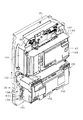
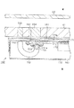
樹脂ベース71の背面には、係止金具135が複数設けられており、これら係止金具135によって上述したように樹脂ベース71に対して遊技盤81が取り付けられている。ここで、遊技盤81の背面の構成を説明する。図9は遊技盤81を後方より見た斜視図、図10は遊技盤81から主制御装置ユニット160を取り外した状態を示す背面図である。   A plurality of locking fittings 135 are provided on the back surface of the resin base 71, and the game board 81 is attached to the resin base 71 by the locking fittings 135 as described above. Here, the configuration of the back surface of the game board 81 will be described. FIG. 9 is a perspective view of the game board 81 as seen from the rear, and FIG. 10 is a rear view showing a state in which the main controller unit 160 is removed from the game board 81.

遊技盤81の中央に配置される可変表示ユニット86には、センターフレーム92を背後から覆う合成樹脂製のフレームカバー141が後方に突出させて設けられており、フレームカバー141に対して後側から上述した図柄表示装置91が取り付けられるとともに、その図柄表示装置を駆動するための表示制御装置が取り付けられている(図示は省略)。これら図柄表示装置91及び表示制御装置は前後方向に重ねて配置され(図柄表示装置が前、表示制御装置が後)、さらにその後方に音声ランプ制御装置ユニット142が搭載されている。音声ランプ制御装置ユニット142は、音声ランプ制御装置143と、取付台144とを具備する構成となっており、取付台144上に音声ランプ制御装置143が装着されている。   The variable display unit 86 disposed in the center of the game board 81 is provided with a frame cover 141 made of synthetic resin that covers the center frame 92 from the back, and is provided rearward with respect to the frame cover 141 from the rear side. The above-described symbol display device 91 is attached, and a display control device for driving the symbol display device is attached (not shown). The symbol display device 91 and the display control device are arranged so as to overlap in the front-rear direction (the symbol display device is in front and the display control device is in rear), and the sound lamp control device unit 142 is mounted on the rear side. The sound lamp control device unit 142 includes a sound lamp control device 143 and a mounting table 144, and the sound lamp control device 143 is mounted on the mounting table 144.

音声ランプ制御装置143は、後述する主制御装置からの指示に従い音声やランプ表示、及び表示制御装置の制御を司る音声ランプ制御基板を具備しており、音声ランプ制御基板が透明樹脂材料等よりなる基板ボックス145に収容されて構成されている。   The sound lamp control device 143 includes a sound lamp control board that controls sound, lamp display, and display control device in accordance with instructions from a main control device to be described later, and the sound lamp control board is made of a transparent resin material or the like. It is configured to be accommodated in a substrate box 145.

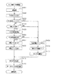
遊技盤81の背面には、図10に示すように、可変表示ユニット86の下方に集合板ユニット150が設けられている。集合板ユニット150には、各種入賞口に入賞した遊技球を回収するための遊技球回収機構や、各種入賞口等への遊技球の入賞を検知するための入賞検知機構などが設けられている。   As shown in FIG. 10, a collective plate unit 150 is provided below the variable display unit 86 on the back surface of the game board 81. The collective board unit 150 is provided with a game ball collecting mechanism for collecting game balls won in various winning ports, a winning detection mechanism for detecting winning of game balls in various winning ports, and the like. .

遊技球回収機構について説明すると、集合板ユニット150には、前記一般入賞口82、可変入賞装置83、作動口84の遊技盤開口部に対応して且つ下流側で1カ所に集合する回収通路151が形成されている。したがって、一般入賞口82等に入賞した遊技球は何れも回収通路151を介して遊技盤81の下方に集合する。遊技盤81の下方には後述する排出通路があり、回収通路151により遊技盤81の下方に集合した遊技球は排出通路内に導出される。なお、アウト口87も同様に排出通路に通じており、何れの入賞口にも入賞しなかった遊技球もアウト口87を介して排出通路内に導出される。   The game ball collecting mechanism will be described. In the collective plate unit 150, a collecting passage 151 that collects in one place on the downstream side corresponding to the game board opening of the general winning port 82, the variable winning device 83, and the operating port 84. Is formed. Therefore, all the game balls that have won the general winning opening 82 and the like gather below the game board 81 via the collection passage 151. Below the game board 81 is a discharge passage which will be described later, and the game balls gathered below the game board 81 by the collection passage 151 are led out into the discharge passage. Similarly, the out port 87 leads to the discharge passage, and a game ball that has not won any winning port is led out into the discharge passage through the out port 87.

入賞検知機構について説明すると、集合板ユニット150には、遊技盤81表側の各一般入賞口82と対応する位置にそれぞれ入賞口スイッチ152a〜152dが設けられている。また、可変入賞装置83と対応する位置にカウントスイッチ153が設けられ、作動口84に対応する位置に作動口スイッチ154が設けられている。これらスイッチ152〜154により遊技球の入賞がそれぞれ検知される。また、集合板ユニット150外における可変表示ユニット86の右側には、スルーゲート85を通過する遊技球を検知するゲートスイッチ155が設けられている。   Explaining the winning detection mechanism, the collective board unit 150 is provided with winning opening switches 152a to 152d at positions corresponding to the respective general winning openings 82 on the front side of the game board 81. A count switch 153 is provided at a position corresponding to the variable winning device 83, and an operation port switch 154 is provided at a position corresponding to the operation port 84. A winning of a game ball is detected by these switches 152 to 154, respectively. A gate switch 155 that detects a game ball passing through the through gate 85 is provided on the right side of the variable display unit 86 outside the collective board unit 150.

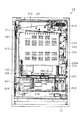
遊技盤81の背面には、集合板ユニット150を後側から覆うようにして主制御装置ユニット160が搭載されている。   A main controller unit 160 is mounted on the back of the game board 81 so as to cover the collective board unit 150 from the rear side.

主制御装置ユニット160は、合成樹脂製の取付台161を有し、取付台161に主制御装置162が搭載されている。取付台161は、ポリカーボネート樹脂などといった透明性を有する合成樹脂により略直方体状に形成されている。取付台161における短辺側の一方の周壁には一対の軸部161aが上下に離間されて一体形成されている。これら軸部161aは集合板ユニット150の下側隅角部に一体形成された一対の支軸部158に着脱自在な状態で片持ち支持されており(図9参照)、取付台161が集合板ユニット150に対して回動可能に支持されている。ここで、集合板ユニット150において支軸部158が形成された位置は本体枠13の回動先端側となっている。つまり、取付台161の回動基端側は本体枠13の回動先端側となっており、取付台161の回動基端側は本体枠13の回動基端側となっている。   The main control unit 160 has a synthetic resin mounting base 161, and the main control unit 162 is mounted on the mounting base 161. The mounting base 161 is formed in a substantially rectangular parallelepiped shape from a synthetic resin having transparency such as polycarbonate resin. A pair of shaft portions 161 a are integrally formed on one peripheral wall on the short side of the mounting base 161 so as to be separated from each other in the vertical direction. These shaft portions 161a are cantilevered in a detachable manner on a pair of support shaft portions 158 formed integrally with the lower corner portion of the collective plate unit 150 (see FIG. 9). The unit 150 is rotatably supported. Here, the position where the support shaft portion 158 is formed in the collective plate unit 150 is the rotation front end side of the main body frame 13. That is, the rotation base end side of the mounting base 161 is the rotation front end side of the main body frame 13, and the rotation base end side of the mounting base 161 is the rotation base end side of the main body frame 13.

主制御装置162は、遊技の主たる制御を司る機能(主制御回路)と、電源を監視する機能(停電監視回路)とを有する主制御基板を具備しており、当該主制御基板が透明樹脂材料等よりなる(透明性を有する)基板ボックス163に収容されて構成されている。主制御装置162の構成については、後に詳細に説明する。   The main controller 162 includes a main control board having a function (main control circuit) that controls the main control of the game and a function (power failure monitoring circuit) that monitors the power source, and the main control board is made of a transparent resin material. Etc. (having transparency) and is accommodated in a substrate box 163. The configuration of main controller 162 will be described in detail later.

次に、裏パックユニット15について説明する。図11は裏パックユニット15の正面図、図12は裏パックユニット15の分解斜視図である。   Next, the back pack unit 15 will be described. FIG. 11 is a front view of the back pack unit 15, and FIG. 12 is an exploded perspective view of the back pack unit 15.

裏パックユニット15は、裏パック201を備えており、当該裏パック201に対して、払出機構部202、排出通路盤203、及び制御装置集合ユニット204が取り付けられている。裏パック201は透明性を有する合成樹脂により成形されており、当該裏パック201によりパチンコ機10の背面部における上半分以上が覆われている。この覆われた領域には、主制御装置162の上部領域及び主制御装置162よりも回動先端側の領域が少なくとも含まれている。但し、上記のとおり裏パック201は透明性を有する合成樹脂により形成されているため、遊技ホールなどに設置されたパチンコ機10において外枠11に対して本体枠13を開き、パチンコ機10の背面部を手前側に開放させることにより、裏パック201により覆われた領域を視認することができる。   The back pack unit 15 includes a back pack 201, and a payout mechanism unit 202, a discharge passage board 203, and a control device collective unit 204 are attached to the back pack 201. The back pack 201 is formed of a synthetic resin having transparency, and the back pack 201 covers the upper half or more of the back portion of the pachinko machine 10. This covered region includes at least the upper region of the main control device 162 and the region on the rotation tip side of the main control device 162. However, since the back pack 201 is formed of a transparent synthetic resin as described above, the main body frame 13 is opened with respect to the outer frame 11 in the pachinko machine 10 installed in a game hall or the like, and the back surface of the pachinko machine 10 is By opening the part to the front side, the area covered by the back pack 201 can be visually recognized.

裏パック201は、払出機構部202などが取り付けられるベース部211と、パチンコ機10後方に突出し略直方体形状をなす保護カバー部212とを有する。保護カバー部212は左右側面及び上面が閉鎖され且つ下面のみが開放された形状をなし、少なくとも可変表示ユニット86を囲むのに十分な大きさを有する。   The back pack 201 includes a base portion 211 to which the payout mechanism portion 202 and the like are attached, and a protective cover portion 212 that protrudes rearward from the pachinko machine 10 and has a substantially rectangular parallelepiped shape. The protective cover portion 212 has a shape in which the left and right side surfaces and the upper surface are closed and only the lower surface is opened, and has a size sufficient to surround at least the variable display unit 86.

ベース部211には、その右上部に外部端子板213が設けられている。外部端子板213には各種の出力端子が設けられており、これらの出力端子を通じて遊技ホール側の管理制御装置に対して各種信号が出力される。また、ベース部211にはパチンコ機10後方からみて右端部に上下一対の掛止ピン214が設けられており、掛止ピン214を本体枠13に設けられた前記軸受け部133に挿通させることで、裏パックユニット15が本体枠13に対して回動可能に支持されている。また、ベース部211には、本体枠13に設けられた被締結孔134に対して締結するための締結具215が設けられており、当該締結具215を被締結孔134に嵌め込むことで本体枠13に対して裏パックユニット15が固定されている。   The base portion 211 is provided with an external terminal plate 213 at the upper right portion thereof. The external terminal board 213 is provided with various output terminals, and various signals are output to the management control device on the game hall side through these output terminals. Further, the base portion 211 is provided with a pair of upper and lower latch pins 214 at the right end when viewed from the rear of the pachinko machine 10, and the latch pins 214 are inserted through the bearing portions 133 provided on the main body frame 13. The back pack unit 15 is rotatably supported with respect to the main body frame 13. In addition, the base 211 is provided with a fastener 215 for fastening to a fastening hole 134 provided in the main body frame 13, and the main body can be obtained by fitting the fastening 215 into the fastening hole 134. A back pack unit 15 is fixed to the frame 13.

ベース部211には、保護カバー部212を迂回するようにして払出機構部202が配設されている。すなわち、裏パック201の最上部には上方に開口したタンク221が設けられており、タンク221には遊技ホールの島設備から供給される遊技球が逐次補給される。タンク221の下方には、下流側に向けて緩やかに傾斜するタンクレール222が連結され、タンクレール222の下流側には上下方向に延びるケースレール223が連結されている。ケースレール223の最下流部には払出装置224が設けられている。払出装置224より払い出された遊技球は、当該払出装置224の下流側に設けられた図示しない払出通路を通じて、裏パック201のベース部211に設けられた遊技球分配部225に供給される。   In the base portion 211, a payout mechanism portion 202 is disposed so as to bypass the protective cover portion 212. That is, a tank 221 opened upward is provided at the uppermost portion of the back pack 201, and the game balls supplied from the island facilities of the game hall are sequentially replenished to the tank 221. A tank rail 222 that is gently inclined toward the downstream side is connected to the lower side of the tank 221, and a case rail 223 that extends in the vertical direction is connected to the downstream side of the tank rail 222. A payout device 224 is provided at the most downstream portion of the case rail 223. The game balls paid out from the payout device 224 are supplied to the game ball distribution unit 225 provided in the base portion 211 of the back pack 201 through a payout passage (not shown) provided on the downstream side of the payout device 224.

遊技球分配部225は、払出装置224より払い出された遊技球を上皿33、下皿34又は後述する排出通路の何れかに振り分けるための機能を有し、内側の開口部226が上述した本体側上皿通路122及び前扉側上皿通路51を介して上皿33に通じ、中央の開口部227が本体側下皿通路123及び前扉側下皿通路52を介して下皿34に通じ、外側の開口部228が排出通路に通じるように形成されている。   The game ball distribution unit 225 has a function of distributing the game balls paid out from the payout device 224 to any one of the upper plate 33, the lower plate 34, and a discharge passage described later, and the inner opening 226 has been described above. The center side opening 227 communicates with the lower plate 34 via the main body side lower plate passage 123 and the front door side lower plate passage 52 through the main body side upper plate passage 122 and the front door side upper plate passage 51. The outer opening 228 is formed to communicate with the discharge passage.

払出機構部202には、裏パック基板229が設置されている。裏パック基板229には、例えば交流24ボルトの主電源が供給され、電源スイッチ229aの切替操作により電源ON又は電源OFFとされるようになっている。   A backpack substrate 229 is installed in the dispensing mechanism unit 202. The back pack substrate 229 is supplied with, for example, a main power of AC 24 volts, and is turned on or off by a switching operation of the power switch 229a.

ベース部211の下端部には、当該下端部を前後に挟むようにして排出通路盤203及び制御装置集合ユニット204が取り付けられている。排出通路盤203は、制御装置集合ユニット204と対向する面に後方に開放された排出通路231が形成されており、当該排出通路231の開放部は制御装置集合ユニット204によって塞がれている。排出通路231は、遊技ホールの島設備等へ遊技球を排出するように形成されており、上述した回収通路151等から排出通路231に導出された遊技球は当該排出通路231を通ることでパチンコ機10外部に排出される。   A discharge passage board 203 and a control device collective unit 204 are attached to the lower end portion of the base portion 211 so as to sandwich the lower end portion in the front-rear direction. The discharge passage board 203 is formed with a discharge passage 231 opened rearward on the surface facing the control device assembly unit 204, and the open portion of the discharge passage 231 is closed by the control device assembly unit 204. The discharge passage 231 is formed so as to discharge the game ball to the island facility or the like of the game hall, and the game ball led out to the discharge passage 231 from the above-described collection passage 151 or the like passes through the discharge passage 231 so as to be pachinko. It is discharged outside the machine 10.

制御装置集合ユニット204は、横長形状をなす取付台241を有し、取付台241に払出制御装置242と電源及び発射制御装置243とが搭載されている。これら払出制御装置242と電源及び発射制御装置243とは、払出制御装置242がパチンコ機10後方となるように前後に重ねて配置されている。   The control device assembly unit 204 has a horizontally long mounting base 241, and a payout control device 242 and a power source and launch control device 243 are mounted on the mounting base 241. The payout control device 242 and the power supply / launch control device 243 are arranged so as to overlap each other so that the payout control device 242 is behind the pachinko machine 10.

払出制御装置242は、基板ボックス244内に払出装置224を制御する払出制御基板が収容されている。なお、払出制御装置242から払出装置224への払出指令の信号は上述した裏パック基板229により中継される。   The payout control device 242 accommodates a payout control board for controlling the payout device 224 in the board box 244. The payout command signal from the payout control device 242 to the payout device 224 is relayed by the back pack substrate 229 described above.

また、払出制御装置242には状態復帰スイッチ245が設けられている。例えば、払出装置224における球詰まり等、払出エラーの発生時において状態復帰スイッチ245が押されると、球詰まりの解消が図られるようになっている。   The payout control device 242 is provided with a state return switch 245. For example, when the state return switch 245 is pressed when a payout error occurs, such as a ball jam in the payout device 224, the ball jam is eliminated.

電源及び発射制御装置243は、基板ボックス246内に電源及び発射制御基板が収容されており、当該基板により、各種制御装置等で要する所定の電力が生成されて出力され、さらに遊技者による遊技球発射ハンドル41の操作に伴う遊技球の打ち出しの制御が行われる。また、電源及び発射制御装置243にはRAM消去スイッチ247が設けられている。本パチンコ機10は各種データの記憶保持機能を有しており、万一停電が発生した際でも停電時の状態を保持し、停電からの復帰の際には停電時の状態に復帰できるようになっている。したがって、例えば遊技ホールの営業終了の場合のように通常手順で電源を遮断すると遮断前の状態が記憶保持されるが、RAM消去スイッチ247を押しながら電源を投入すると、RAMデータが初期化されるようになっている。   The power source and launch control device 243 includes a power source and launch control board housed in the board box 246, and the board generates and outputs predetermined power required by various control devices and the like, and further a game ball by the player Control of the launch of the game ball accompanying the operation of the firing handle 41 is performed. Further, the power and launch control device 243 is provided with a RAM erase switch 247. This pachinko machine 10 has a function to store and store various data so that even if a power failure occurs, it maintains the state at the time of the power failure, and when it recovers from the power failure, it can be restored to the state at the time of the power failure. It has become. Therefore, for example, when the power supply is turned off in the normal procedure, as in the case of the game hall being closed, the state before the turn-off is stored and held. It is like that.

次に、主制御装置162について説明する。図13(a)は主制御装置162の正面図、図13(b)は主制御装置162の側面図である。   Next, the main controller 162 will be described. FIG. 13A is a front view of the main controller 162, and FIG. 13B is a side view of the main controller 162.

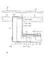
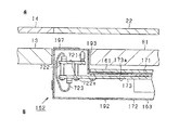
主制御装置162は、上記のとおり、基板ボックス163を備えている。基板ボックス163は、略直方体形状のボックスベース(裏ケース体)171とこのボックスベース171の開口部を覆うボックスカバー(表ケース体)172とを備えている。そして、これらボックスベース171とボックスカバー172とを相互に組み付けることにより形成される内部空間内に主制御基板173が収容されている。   The main control device 162 includes the substrate box 163 as described above. The board box 163 includes a box base (back case body) 171 having a substantially rectangular parallelepiped shape and a box cover (front case body) 172 that covers an opening of the box base 171. The main control board 173 is accommodated in an internal space formed by assembling the box base 171 and the box cover 172 with each other.

主制御基板173は、その部品搭載面173aがボックスカバー172側を向くようにして設置されている(図14参照)。この場合、主制御装置162は、ボックスカバー172がボックスベース171よりもパチンコ機10後方においてこれらボックスベース171とボックスカバー172とが前後に並ぶようにして設置されている。したがって、主制御基板173の部品搭載面173aは、パチンコ機10後方を向いている。   The main control board 173 is installed such that the component mounting surface 173a faces the box cover 172 side (see FIG. 14). In this case, the main control device 162 is installed such that the box cover 172 and the box cover 172 are arranged in the front-rear direction behind the pachinko machine 10 with respect to the box base 171. Therefore, the component mounting surface 173 a of the main control board 173 faces the back of the pachinko machine 10.

主制御基板173は、各種スイッチ152〜155と電気的に接続されているとともに、払出制御基板と電気的に接続されている。この電気的な接続は、ハーネスなどの電気配線を介して行われている。払出制御基板との電気的な接続について例示すると、図4に示すように、主制御基板173に設けられたコネクタCN1と払出制御基板に設けられたコネクタCN2とがハーネスHによって電気的に接続されている。   The main control board 173 is electrically connected to the various switches 152 to 155 and electrically connected to the payout control board. This electrical connection is made through electrical wiring such as a harness. Exemplifying the electrical connection with the payout control board, as shown in FIG. 4, the connector CN1 provided on the main control board 173 and the connector CN2 provided on the payout control board are electrically connected by a harness H. ing.

ボックスベース171とボックスカバー172とは結合手段としての結合部174によって結合され、その結合を解除する際には結合部174の破壊を要する。結合部174は、基板ボックス163の長辺部に5つ設けられ、そのうち少なくとも一つが用いられて結合処理が行われる。   The box base 171 and the box cover 172 are coupled by a coupling part 174 as coupling means, and the coupling part 174 needs to be broken when the coupling is released. Five coupling portions 174 are provided on the long side portion of the substrate box 163, and at least one of them is used for the coupling process.

結合部174はボックスベース171とボックスカバー172とを開封不能に結合する構成であれば任意の構成が適用できるが、結合部174を構成する長孔に係止爪を挿入することでボックスベース171とボックスカバー172とが開封不能に結合されるようになっている。結合部174による結合処理は、その結合後の不正な開封を防止し、また万一不正開封が行われてもそのような事態を早期に且つ容易に発見可能とするものであって、一旦開封した後でも再度結合処理を行うこと自体は可能である。すなわち、5つの結合部174のうち、少なくとも一つの長孔に係止爪を挿入することにより結合処理が行われる。そして、収容した主制御基板173の不具合発生の際や主制御基板173の検査の際など基板ボックス163を開封する場合には、係止爪が挿入された結合部174と他の結合部174との連結部分を切断する。これにより、ボックスベース171とボックスカバー172とを相互に分離させることが可能となり、内部の主制御基板173を取り出すことができる。その後、再度結合処理する場合は他の結合部174の長孔に係止爪を挿入する。基板ボックス163の開封を行った旨の履歴を当該基板ボックス163に残しておけば、基板ボックス163を見ることで不正な開封が行われた旨が容易に発見できる。   Any configuration can be applied to the coupling portion 174 as long as the box base 171 and the box cover 172 are coupled so as not to be opened, but the box base 171 can be inserted by inserting a locking claw into the long hole constituting the coupling portion 174. And the box cover 172 are coupled so as not to be opened. The coupling process by the coupling unit 174 prevents unauthorized opening after the coupling, and makes it possible to detect such a situation early and easily even if unauthorized opening is performed. Even after this, it is possible to perform the joining process again. That is, the coupling process is performed by inserting a locking claw into at least one of the five coupling portions 174. When the board box 163 is opened such as when a failure occurs in the accommodated main control board 173 or when the main control board 173 is inspected, the coupling portion 174 into which the locking claw is inserted and the other coupling portion 174 Cut the connecting part. Thereby, the box base 171 and the box cover 172 can be separated from each other, and the internal main control board 173 can be taken out. Thereafter, when the coupling process is performed again, the locking claw is inserted into the long hole of the other coupling part 174. If the history of opening the substrate box 163 is left in the substrate box 163, it can be easily found that the unauthorized opening has been performed by looking at the substrate box 163.

また、ボックスベース171及びボックスカバー172には、板状のシール貼付部175a,175bがそれぞれ一体形成されており、ボックスベース171とボックスカバー172とを組み付けた状態では両シール貼付部175a,175bが相互に重なり合う。この重なり合った両シール貼付部175a,175bに跨るようにして封印シール176が貼付されている。封印シール176は、一旦貼付された後に剥がされるとシールラベルから粘着剤が剥がれ、再度貼付することができないものであり、封印シール176が剥がされた場合にはその形跡が残ることから、基板ボックス163が不正に開封されたかどうかが確認できるものとなっている。   The box base 171 and the box cover 172 are integrally formed with plate-like seal attaching portions 175a and 175b. When the box base 171 and the box cover 172 are assembled, the both seal attaching portions 175a and 175b are formed. Overlap each other. A seal seal 176 is affixed so as to straddle both the overlapping seal affixing portions 175a and 175b. When the seal seal 176 is once applied and then peeled off, the adhesive is peeled off from the seal label and cannot be applied again. When the seal seal 176 is peeled off, the trace remains, so the substrate box It is possible to confirm whether or not 163 has been opened illegally.

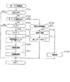
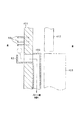
以上の構成の主制御装置162において、本パチンコ機10では、主制御装置162の基板ボックス163内に発光体ユニット181a,181b,181cが収容されている。ここで、発光体ユニット181a,181b,181c及びそれに関する構成について以下に詳述する。図14は発光体ユニット181a〜181cを説明するための主制御装置162の側面概略図、図15は発光体ユニット181a〜181cを説明するための主制御装置162の横断面概略図である。   In the main controller 162 configured as described above, in the pachinko machine 10, the light emitter units 181a, 181b, and 181c are accommodated in the board box 163 of the main controller 162. Here, the light emitter units 181a, 181b, 181c and the configuration related thereto will be described in detail below. 14 is a schematic side view of the main controller 162 for explaining the light emitter units 181a to 181c. FIG. 15 is a schematic cross-sectional view of the main controller 162 for explaining the light emitter units 181a to 181c.

図14に示すように、基板ボックス163内には、複数の発光体ユニット181a,181b,181cが収容されている。各発光体ユニット181a,181b,181cはそれぞれ同一の構成をなしており、各発光体ユニット181a〜181cは、多色発光タイプのLED(発光体)182a,182b,182cが搭載されたLED基板(発光体用基板)183a,183b,183cを有しているとともに、当該LED基板183a,183b,183cを収容するケース体184a,184b,184cを有している。   As shown in FIG. 14, a plurality of light emitter units 181 a, 181 b, and 181 c are accommodated in the substrate box 163. Each of the light emitter units 181a, 181b, 181c has the same configuration, and each of the light emitter units 181a to 181c is an LED board (on which multicolor light emitting type LEDs (light emitters) 182a, 182b, 182c are mounted). (Luminous substrate) 183a, 183b, 183c and case bodies 184a, 184b, 184c for housing the LED substrates 183a, 183b, 183c.

ケース体184a〜184cは、ポリカーボネートなどといった透明性を有する合成樹脂により形成されており、図15に示すように、略L字状をなし、長手部185a〜185cと短手部186a〜186cとを有している。   The case bodies 184a to 184c are formed of a synthetic resin having transparency such as polycarbonate, and as shown in FIG. 15, the case bodies 184a to 184c are substantially L-shaped, and have a long portion 185a to 185c and a short portion 186a to 186c. Have.

長手部185a〜185cにはLED基板183a〜183cが収容されている。この場合、LED基板183a〜183cにはその一端にLED182a〜182cが搭載されており、当該LED182a〜182cが長手部185a〜185cの先端に位置するようにしてLED基板183a〜183cが収容されている。また、LED182a〜182cがLED基板183a〜183cの板面から突出していることに対応させて、長手部185a〜185cの先端にはLED用収容部(発光体用収容部)187a〜187cが一体形成されている(図14参照)。   LED boards 183a-183c are accommodated in the longitudinal portions 185a-185c. In this case, the LED boards 183a to 183c are mounted with LEDs 182a to 182c at one end thereof, and the LED boards 183a to 183c are accommodated so that the LEDs 182a to 182c are positioned at the tips of the long portions 185a to 185c. . Further, LED housing portions (light emitting body housing portions) 187a to 187c are integrally formed at the tips of the long portions 185a to 185c in correspondence with the LEDs 182a to 182c projecting from the plate surfaces of the LED substrates 183a to 183c. (See FIG. 14).

LED用収容部187a〜187cは、長手部185a〜185cの長さ方向(延びる方向)に対して垂直方向に突出させて設けられている。また、LED用収容部187a〜187cには、LED182a〜182cから照射された光を極力広角度に分散させるための分散手段が付与されている。具体的には、LED用収容部187a〜187cには、微小なラメ素材が極力均一に分散させて付与されている。この分散手段により、LED182a〜182cから照射された光は、各LED182a〜182cの軸線を中心として180°の方向に分散されるようになっている。なお、ケース体184a〜184cを、微小なラメ素材を分散させた合成樹脂により形成することで、LED用収容部187a〜187cに分散手段を付与するようにしてもよい。   The LED accommodating portions 187a to 187c are provided so as to protrude in the vertical direction with respect to the length direction (extending direction) of the longitudinal portions 185a to 185c. The LED accommodating portions 187a to 187c are provided with a dispersing means for dispersing light emitted from the LEDs 182a to 182c at a wide angle as much as possible. Specifically, minute glitter materials are dispersed and applied as uniformly as possible to the LED accommodating portions 187a to 187c. By this dispersing means, the light emitted from the LEDs 182a to 182c is dispersed in the direction of 180 ° around the axis of each LED 182a to 182c. In addition, you may make it provide a dispersion | distribution means to the accommodating parts 187a-187c for LED by forming the case bodies 184a-184c from the synthetic resin which disperse | distributed the fine glitter material.

短手部186a〜186cにはその先端にコネクタ188a,188b,188cが設けられている。詳細には、コネクタ188a〜188cは、短手部186a〜186cの先端において長手部185a〜185cが延びる方向と同一方向を向くようにして設けられている。このコネクタ188a〜188cは、ケース体184a〜184c内において電気配線189a,189b,189cを介してLED基板183a〜183cに接続されている。   Connectors 188a, 188b, and 188c are provided at the tips of the short portions 186a to 186c. Specifically, the connectors 188a to 188c are provided at the tips of the short portions 186a to 186c so as to face the same direction as the direction in which the long portions 185a to 185c extend. The connectors 188a to 188c are connected to the LED boards 183a to 183c via electric wirings 189a, 189b, and 189c in the case bodies 184a to 184c.

上記構成の各発光体ユニット181a〜181cは、主制御装置162の一端側であって、本体枠13の回動先端側に位置するように設けられている。詳細には、主制御基板173の部品搭載面173aにおける本体枠13の回動先端側に相当する端部には、各発光体ユニット181a〜181cに1対1で対応させてコネクタ191a,191b,191cが設けられている(以下、コネクタ191a〜191cを基板側コネクタ191a〜191cともいう)。これら各基板側コネクタ191a〜191cは上下に並設されている。各発光体ユニット181a〜181cは、長手部185a〜185cが主制御基板173よりも回動先端側に位置するようにして、上記各コネクタ188a〜188cが対応する各基板側コネクタ191a〜191cに接続されている。そして、各発光体ユニット181a〜181cの各LED182a〜182cは、主制御基板173から動作電力が供給されるとともに、主制御基板173により個別に発光制御される。なお、長手部185a〜185cのLED用収容部187a〜187cは下方を向いているが、上方を向く構成としてもよい。   Each of the light emitter units 181a to 181c having the above-described configuration is provided on one end side of the main controller 162 and on the rotating front end side of the main body frame 13. Specifically, on the component mounting surface 173a of the main control board 173, the end corresponding to the rotating front end side of the main body frame 13 has a one-to-one correspondence with each of the light emitter units 181a to 181c, and the connectors 191a, 191b, 191c is provided (hereinafter, the connectors 191a to 191c are also referred to as board-side connectors 191a to 191c). Each of these board-side connectors 191a to 191c is arranged in parallel up and down. Each of the light emitter units 181a to 181c is connected to each of the board side connectors 191a to 191c corresponding to each of the connectors 188a to 188c so that the longitudinal portions 185a to 185c are positioned on the rotating tip side of the main control board 173. Has been. The LEDs 182a to 182c of the light emitter units 181a to 181c are supplied with operating power from the main control board 173 and are individually controlled to emit light by the main control board 173. The LED housing portions 187a to 187c of the longitudinal portions 185a to 185c face downward, but may be configured to face upward.

上記のように発光体ユニット181a〜181cが取り付けられた構成においては、発光体ユニット181a〜181cの長手部185a〜185cは、図15に示すように、主制御基板173よりもボックスベース171側に延出することとなる。これに対して、ボックスベース171には、当該長手部185a〜185cを収容するための膨出部が一体形成されている。つまり、ボックスベース171は、主として主制御基板173を収容するための機能を有する基板収容部192と、主として発光体ユニット181a〜181cを収容するための機能を有する発光体収容部193とを有している。さらに言うと、基板ボックス163は、主として主制御基板173を収容するための機能を有する基板収容部192と、主として発光体ユニット181a〜181cを収容するための機能を有する発光体収容部193とを有している。   In the configuration in which the light emitter units 181a to 181c are attached as described above, the longitudinal portions 185a to 185c of the light emitter units 181a to 181c are closer to the box base 171 than the main control board 173, as shown in FIG. It will be extended. On the other hand, the box base 171 is integrally formed with a bulging portion for accommodating the longitudinal portions 185a to 185c. That is, the box base 171 has a substrate housing part 192 mainly having a function for housing the main control board 173 and a light emitter housing part 193 mainly having a function for housing the light emitter units 181a to 181c. ing. Furthermore, the substrate box 163 includes a substrate housing portion 192 mainly having a function for housing the main control board 173 and a light emitter housing portion 193 mainly having a function for housing the light emitter units 181a to 181c. Have.

発光体収容部193の内部空間は、図14に示すように、2つの仕切板194a,194bにより仕切られて上下方向に3つの領域に区画されている。そして、各領域にそれぞれ1つの発光体ユニット181a〜181cが収容されている。なお、仕切板194a,194bは、有色の材料により形成されており、各発光体ユニット181a〜181cのLED182a〜182cからの光が他の発光体ユニット181a〜181cの領域内に入り込まないようになっている。なお、仕切板194a,194bを備えていなくともよい。   As shown in FIG. 14, the internal space of the light emitter housing part 193 is partitioned by two partition plates 194a and 194b and is partitioned into three regions in the vertical direction. One light emitter unit 181a to 181c is accommodated in each region. The partition plates 194a and 194b are formed of a colored material so that light from the LEDs 182a to 182c of the respective light emitter units 181a to 181c does not enter the region of the other light emitter units 181a to 181c. ing. The partition plates 194a and 194b may not be provided.

発光体収容部193は、基板収容部192よりもパチンコ機10前方に膨出しており、その先端側の端面は遊技盤81の裏面(背面)に近い位置にて対峙している。この場合、上段に位置している発光体ユニット181a(以下、第1発光体ユニット181aともいう)は、第1特定発光部94の後方にあり、中段に位置している発光体ユニット181b(以下、第2発光体ユニット181bともいう)は、第2特定発光部95の後方にあり、下段に位置している発光体ユニット181c(以下、第3発光体ユニット181cともいう)は、第3特定発光部96の後方にある。そして、第1発光体ユニット181aのLED182a(以下、第1LED182aともいう)から照射された光は第1特定発光部94を透過し、第2発光体ユニット181bのLED182b(以下、第2LED182bともいう)から照射された光は第2特定発光部95を透過し、第3発光体ユニット181cのLED182c(以下、第3LED182cともいう)から照射された光は第3特定発光部96を透過する。   The light emitter housing portion 193 bulges in front of the pachinko machine 10 with respect to the substrate housing portion 192, and the end surface on the front end side faces the back surface (back surface) of the game board 81. In this case, the light emitter unit 181a (hereinafter also referred to as the first light emitter unit 181a) located in the upper stage is located behind the first specific light emitting unit 94 and is located in the middle stage (hereinafter referred to as the light emitter unit 181b). , The second light emitter unit 181b) is located behind the second specific light emitter 95, and the lower light emitter unit 181c (hereinafter also referred to as the third light emitter unit 181c) is the third specific light emitter unit 181b. It is behind the light emitting unit 96. The light emitted from the LED 182a (hereinafter also referred to as the first LED 182a) of the first light emitter unit 181a passes through the first specific light emitter 94, and the LED 182b (hereinafter also referred to as the second LED 182b) of the second light emitter unit 181b. The light emitted from the second specific light emitting unit 95 is transmitted through the second specific light emitting unit 95, and the light emitted from the LED 182c (hereinafter also referred to as the third LED 182c) of the third light emitting unit 181c is transmitted through the third specific light emitting unit 96.

ここで、上記のとおり、第1特定発光部94では、各遊技回において大当たりの発生の有無が報知され、第2特定発光部95では、大当たりが発生した際に、ラウンドの規定回数がいずれのパターンかが報知され、第3特定発光部96では、作動口84に付随する電動役物84aを開放状態とするか否かの報知が行われる。つまり、主制御基板173により第1LED182aが発光制御されることにより、各遊技回において大当たりの発生の有無が報知され、主制御基板173により第2LED182bが発光制御されることにより、大当たりが発生した際に、ラウンドの規定回数がいずれのパターンかが報知され、主制御基板173により第3LED182cが発光制御されることにより、作動口84に付随する電動役物84aを開放状態とするか否かが報知される。   Here, as described above, the first specific light emitting unit 94 is notified of the presence or absence of a jackpot at each game time, and the second specific light emitting unit 95 determines which number of rounds the prescribed number of times when a jackpot occurs. The third specific light emitting unit 96 notifies whether or not the electric accessory 84a associated with the operation port 84 is in an open state. In other words, when the first LED 182a is controlled to emit light by the main control board 173, the presence / absence of occurrence of a big hit is notified at each game time, and when the second LED 182b is controlled to emit light by the main control board 173, In addition, it is notified which pattern the prescribed number of rounds is in, and whether or not the electric accessory 84a associated with the operating port 84 is opened by the third control circuit 173 controlling the light emission of the third LED 182c. Is done.

各LED182a〜182cは、上記のように各種遊技状況を報知する機能だけでなく、主制御基板173が正常に動作している旨を報知する機能を有している。なお、「正常に動作している」とは、本パチンコ機10では、主制御基板173に動作電力が供給されており、且つ制御対象の各機器が主制御基板173に電気的に接続されていることを言う。但し、主制御基板173に動作電力が供給されていることのみを「正常に動作している」こととしてもよい。つまり、「正常に動作している」とは、主制御基板173に少なくとも動作電力が供給さていることを言う。   Each LED 182a to 182c has not only a function of notifying various game situations as described above, but also a function of notifying that the main control board 173 is operating normally. In this pachinko machine 10, “operating normally” means that the operating power is supplied to the main control board 173 and each control target device is electrically connected to the main control board 173. Say that. However, only that the operating power is supplied to the main control board 173 may be “normally operating”. That is, “operating normally” means that at least operating power is supplied to the main control board 173.

上記主制御基板173が正常に動作している旨を報知する機能について詳細には、主制御基板173が正常に動作している場合、遊技状況の報知を行うタイミングか否かに関係なく、各LED182a〜182cには主制御基板173から常に動作電力が供給される。これにより、各LED182a〜182cからは、主制御基板173が正常に動作している場合、常に光が照射される。この各LED182a〜182cから照射された光は、対応する特定発光部94〜96を透過する。そして、各特定発光部94〜96は遊技領域内に設けられているため、遊技ホールの管理者等にとっては、上記各LED182a〜182cから照射された光を、遊技ホールに設置状態にあり、且つ本体枠13や前扉枠14の開放操作が行われていない状態において、パチンコ機10前方から視認することができる。   The function for notifying that the main control board 173 is operating normally will be described in detail. When the main control board 173 is operating normally, regardless of whether or not it is the timing to notify the game situation, Operating power is always supplied from the main control board 173 to the LEDs 182a to 182c. As a result, the LEDs 182a to 182c are always irradiated with light when the main control board 173 is operating normally. The light emitted from each of the LEDs 182a to 182c passes through the corresponding specific light emitting units 94 to 96. And since each specific light emission part 94-96 is provided in the game area | region, for the manager of a game hall, etc., the light irradiated from each said LED182a-182c is in the installation state in a game hall, and When the opening operation of the main body frame 13 or the front door frame 14 is not performed, it can be visually recognized from the front of the pachinko machine 10.

パチンコ機10においては、主制御装置162と他の機器との電気的な接続を全て外し、代わりにそれら他の機器と不正基板とを電気的に接続させる不正行為が想定され、この場合、不正基板により例えば払出制御装置242が制御され、遊技球の不正な払い出しが実行されてしまう。また、上記不正行為が、他の機器との電気的な接続を解除した主制御装置162をそのまま残した状態とするとともに、不正基板を主制御装置162などによって隠される領域に配置されてしまうと、当該不正行為の発見は容易ではない。そうすると、遊技球の不正な払い出しなどが長期間に亘って行われ、遊技ホールに多大な不利益を及ぼしてしまうおそれがある。また、遊技ホールには多数のパチンコ機10が設置されているため、日常の点検において不正基板への交換が行われていないか否かを1台ずつ入念に点検しないといけないとすると、多大な労力を必要とし、好ましくない。これに対して、上記のとおり、各LED182a〜182cから照射される光により主制御基板173が正常に動作していることが報知され、さらにその光は、本体枠13や前扉枠14の開放操作を要することなくパチンコ機10前方から視認することができる。よって、上記不正行為が行われているか否かの確認作業を容易に行うことができる。   In the pachinko machine 10, it is assumed that a fraudulent act of disconnecting all electrical connections between the main controller 162 and other devices, and electrically connecting the other devices and the unauthorized substrate, For example, the payout control device 242 is controlled by the board, and illegal payout of the game ball is executed. Further, when the above-mentioned fraudulent action leaves the main control device 162 that has been disconnected from the electrical connection with other devices as it is, the fraudulent board is placed in an area hidden by the main control device 162 or the like. , It is not easy to detect the fraud. If it does so, illegal payout of a game ball, etc. will be performed over a long period of time, and there is a possibility of giving a great disadvantage to a game hall. In addition, since a large number of pachinko machines 10 are installed in the game hall, it is enormous if it is necessary to carefully check whether or not each board has been replaced with an illegal board in daily inspection. It requires labor and is not preferable. On the other hand, as described above, it is notified that the main control board 173 is operating normally by the light emitted from the LEDs 182a to 182c, and the light is further released from the main body frame 13 and the front door frame 14. It can be visually recognized from the front of the pachinko machine 10 without requiring an operation. Therefore, it is possible to easily confirm whether or not the above fraud is being performed.

また、LED182a〜182cは、主制御基板173と共に、主制御装置162の基板ボックス163内に収容されている。そして、基板ボックス163には、上記のとおり、結合部174又は封印シール176が設けられており、基板ボックス163の開封を容易に行うことができないようになっているだけでなく、開封に際して痕跡が残ることから基板ボックス163を不正に開封しようとする行為を思い留まらせることができるようになっている。よって、LED182a〜182cに対する不正行為が抑制され、LED182a〜182cによる上記報知の信頼性が高められている。例えば、LED182a〜182cが基板ボックス163の外部に設けられた構成を想定すると、その外部に設けられたLED182a〜182cと主制御基板173との電気的な接続を解除し、当該LED182a〜182cを不正基板に接続することで、LED182a〜182cによる報知内容を不正に操作することができてしまうからである。   The LEDs 182a to 182c are housed in the board box 163 of the main controller 162 together with the main control board 173. As described above, the board box 163 is provided with the coupling portion 174 or the seal seal 176 so that the board box 163 cannot be easily opened, and there is no trace at the time of opening. Since it remains, it is possible to discourage the act of illegally opening the board box 163. Therefore, the illegal act with respect to LED182a-182c is suppressed, and the reliability of the said alerting | reporting by LED182a-182c is improved. For example, assuming a configuration in which the LEDs 182a to 182c are provided outside the board box 163, the electrical connection between the LEDs 182a to 182c and the main control board 173 provided outside the board box 163 is canceled, and the LEDs 182a to 182c are illegal. This is because the notification content by the LEDs 182a to 182c can be illegally operated by connecting to the substrate.

上記のようにLED182a〜182cから照射された光は、パチンコ機10前方から視認可能であるが、さらに本体枠13を開放操作した場合にはその開放操作した本体枠13の側方及び後方(すなわち、背面側)からも視認することができるようになっている。   As described above, the light emitted from the LEDs 182a to 182c is visible from the front of the pachinko machine 10, but when the main body frame 13 is further opened, the side and rear of the opened main body frame 13 (that is, the rear side) It can be visually recognized from the back side.

当該構成について詳細には、上記のとおり基板ボックス163は透明性を有する材料により形成されているとともに、発光体ユニット181a〜181cのケース体184a〜184cも透明性を有する材料により形成されている。よって、LED182a〜182cから照射される光を、基板ボックス163の外部から視認することができる。また、発光体ユニット181a〜181cは、基板ボックス163において基板収容部192よりもパチンコ機10前方に膨出した発光体収容部193に収容されているが、図9に示すように、発光体収容部193は基板ボックス163の左右方向の一端に設けられており、さらに取付台161には発光体収容部193を露出させるための切欠部161bが形成されている。また、図4に示すように、発光体収容部193は、裏パックユニット15の裏パック201により覆われているが、裏パック201は透明性を有しているため、その覆われた状態において発光体収容部193を視認することができる。さらに、上記のとおり発光体ユニット181a〜181cにおけるケース体184a〜184cのLED用収容部187a〜187cには分散手段が付与されており、LED182a〜182cからの光は各LED182a〜182cの軸線を中心として180°の方向に分散されるようになっている。以上の構成により、LED182a〜182cから照射された光は、本体枠13を開放操作した場合には、裏パックユニット15の本体枠13に対する開放操作や主制御装置162の取り外し操作を要することなく、開放操作した本体枠13の側方及び後方から視認することができる。よって、本体枠13を開放操作してLED182a〜182cを確認する場合においても、その作業性の向上が図られている。   Specifically, as described above, the substrate box 163 is formed of a transparent material, and the case bodies 184a to 184c of the light emitter units 181a to 181c are also formed of a transparent material. Therefore, the light emitted from the LEDs 182a to 182c can be viewed from the outside of the substrate box 163. In addition, the light emitter units 181a to 181c are accommodated in the light emitter accommodating portion 193 that swells in front of the pachinko machine 10 from the substrate accommodating portion 192 in the substrate box 163. As illustrated in FIG. The part 193 is provided at one end of the board box 163 in the left-right direction, and the mounting base 161 is formed with a notch 161b for exposing the light emitter housing part 193. Further, as shown in FIG. 4, the light emitter housing portion 193 is covered with the back pack 201 of the back pack unit 15, but the back pack 201 has transparency, so in the covered state. The light emitter housing portion 193 can be visually recognized. Further, as described above, the LED accommodating portions 187a to 187c of the case bodies 184a to 184c in the light emitter units 181a to 181c are provided with dispersing means, and the light from the LEDs 182a to 182c is centered on the axis of each LED 182a to 182c. Is distributed in the direction of 180 °. With the above configuration, the light emitted from the LEDs 182a to 182c does not require the opening operation of the back pack unit 15 with respect to the main body frame 13 or the removal operation of the main controller 162 when the main body frame 13 is opened. It can be visually recognized from the side and rear of the body frame 13 that has been opened. Therefore, even when the body frame 13 is opened to check the LEDs 182a to 182c, the workability is improved.

また、上記のように、各発光体ユニット181a〜181cは、本体枠13の回動先端側に設けられている。したがって、本体枠13を僅かに開放させるだけで上記確認を行うことができ、また本体枠13を前方に開放させると各LED182a〜182cはパチンコ機10前方の位置へと導かれ、上記確認作業を無理なく行うことができる。よって、上記確認作業の容易化が図られている。さらにまた、上記のように各発光体ユニット181a〜181cが本体枠13の回動先端側に設けられていることにより、各LED182a〜182c自体を容易に視認することができる。このように各LED182a〜182c自体を容易に視認可能とすることで、各LED182a〜182cと各特定発光部94〜96との間に偽LED等が設置されていないか否かを確認することができる。   Further, as described above, each of the light emitter units 181 a to 181 c is provided on the rotating front end side of the main body frame 13. Therefore, the above confirmation can be performed by slightly opening the main body frame 13, and when the main body frame 13 is opened forward, the LEDs 182a to 182c are guided to positions in front of the pachinko machine 10, and the above confirmation work is performed. It can be done without difficulty. Therefore, the confirmation work is facilitated. Furthermore, since each light emitter unit 181a to 181c is provided on the rotating front end side of the main body frame 13 as described above, each LED 182a to 182c itself can be easily visually recognized. Thus, by making each LED 182a to 182c itself visible easily, it is possible to confirm whether or not a false LED or the like is installed between each LED 182a to 182c and each specific light emitting unit 94 to 96. it can.

主制御装置162には、上記のとおり基板用証紙197が設けられている。この基板用証紙197について図13(b)及び図14等を用いて詳細に説明する。   The main controller 162 is provided with the board certificate paper 197 as described above. The board certificate paper 197 will be described in detail with reference to FIGS.

主制御装置162の基板ボックス163には、上記のとおり、基板収容部192と発光体収容部193とが設けられており、発光体収容部193は基板収容部192よりもパチンコ機10前方に膨出している。つまり、発光体収容部193が前方膨出領域に相当する。この発光体収容部193の先端側の端面に基板用証紙197が貼り付けられている。   The board box 163 of the main controller 162 is provided with the board housing part 192 and the light emitter housing part 193 as described above, and the light emitter housing part 193 swells in front of the pachinko machine 10 with respect to the board housing part 192. I'm out. That is, the light emitter housing portion 193 corresponds to the front bulging region. A board certificate paper 197 is affixed to the end face on the front end side of the light emitter housing portion 193.

ここで、上記のとおり発光体収容部193は発光体ユニット181a〜181cを収容する機能を有している。そして、発光体ユニット181a〜181cのLED182a〜182cから照射された光は、発光体収容部193を透過し特定発光部94〜96に到達する。したがって、基板用証紙197は、LED182a〜182cから照射された光の特定発光部94〜96への導入を阻害しない位置に貼り付けられている。詳細には、基板用証紙197は、LED182a〜182cと正面視で重ならないように、LED182a〜182cに対して下方にずらした位置に貼り付けられている。なお、基板用証紙197をLED182a〜182cに対して上方又は左右にずらした位置に貼り付けてもよい。   Here, as described above, the light emitter housing portion 193 has a function of housing the light emitter units 181a to 181c. And the light irradiated from LED182a-182c of the light-emitting unit 181a-181c permeate | transmits the light-emitting body accommodating part 193, and reaches | attains the specific light emission parts 94-96. Therefore, the board certificate paper 197 is affixed at a position where the introduction of the light emitted from the LEDs 182a to 182c into the specific light emitting units 94 to 96 is not hindered. Specifically, the board certificate paper 197 is attached to a position shifted downward with respect to the LEDs 182a to 182c so as not to overlap with the LEDs 182a to 182c in a front view. In addition, you may affix the board certificate paper 197 in the position shifted upwards or right and left with respect to LED182a-182c.

発光体収容部193の先端側の端面は上記のとおり遊技盤81の裏面と近い位置にて対峙しているため、基板用証紙197も遊技盤81の裏面と近い位置にて対峙している。そして、基板用証紙197の前方に証紙透過部104が位置している。証紙透過部104の構成については、既に説明したとおりである。当該構成であることにより、遊技ホールに設置状態にあり且つ本体枠13や前扉枠14の開放操作が行われていない状態において、遊技領域用窓部20及び証紙透過部104を通じてパチンコ機10前方から基板用証紙197を視認することができる。   Since the end surface on the front end side of the light emitter housing portion 193 faces the position close to the back surface of the game board 81 as described above, the board certificate paper 197 also faces the position close to the back surface of the game board 81. The certificate paper transmitting portion 104 is positioned in front of the substrate certificate paper 197. The configuration of the certificate paper transmitting unit 104 is as described above. Due to this configuration, the pachinko machine 10 is located in front of the pachinko machine 10 through the game area window portion 20 and the certificate paper transmission portion 104 when the main body frame 13 and the front door frame 14 are not opened. The board certificate 197 can be visually recognized.

ここで、発光体収容部193には、基板用証紙197の貼り付け位置を規定するための位置決め部198が一体形成されている。位置決め部198は、発光体収容部193の先端側の端面から前方に突出させて形成されており、さらに基板用証紙197の貼り付け領域を区画するようにして形成されている。この場合、位置決め部198を、連続的又は断続的な枠状に形成してもよく、少なくとも上下方向の一方及び少なくとも左右方向の一方の貼り付け位置を規定するようにL字状に形成してもよい。さらには、発光体収容部193の先端側の端面から前方に突出させずに線や溝などによって形成してもよい。但し、位置決め部198を突出させて形成する構成においては物理的な位置決め機能を有するが、突出させずに形成する構成においては物理的な位置決め機能を有さないものとなる。位置決め部198が形成されていることにより、基板用証紙197の基板ボックス163への貼り付け作業時において基板用証紙197が位置決めされ、主制御装置162を遊技盤81に搭載した際には基板用証紙197は自ずと証紙透過部104の後方に配置される。   Here, the light emitter housing portion 193 is integrally formed with a positioning portion 198 for defining a position where the board certificate paper 197 is attached. The positioning portion 198 is formed so as to protrude forward from the end surface on the front end side of the light emitter housing portion 193, and is further formed so as to partition an attachment region of the board certificate paper 197. In this case, the positioning portion 198 may be formed in a continuous or intermittent frame shape, and is formed in an L shape so as to define at least one attachment position in the vertical direction and at least one horizontal direction. Also good. Furthermore, it may be formed by a line, a groove, or the like without protruding forward from the end face on the front end side of the light emitter housing portion 193. However, the configuration in which the positioning portion 198 is formed so as to protrude has a physical positioning function, but the configuration in which the positioning portion 198 is formed without protruding does not have a physical positioning function. Since the positioning portion 198 is formed, the board certificate paper 197 is positioned at the time of attaching the board certificate paper 197 to the board box 163, and when the main controller 162 is mounted on the game board 81, The certificate paper 197 is naturally arranged behind the certificate paper transmitting portion 104.

基板用証紙197は、図7に示すように、その表面にパチンコ機10の機種名(具体的には、「○○物語」)及び型式名(具体的には、「M−1」)が記されている。なお、基板用証紙197に、上記機種名及び型式名に加えて、パチンコ機10の製造メーカ名、パチンコ機10の製造番号又は主制御装置162の製造番号などを記すようにしてもよい。   As shown in FIG. 7, the board certificate paper 197 has a model name (specifically “XXX story”) and a model name (specifically “M-1”) of the pachinko machine 10 on its surface. It is written. In addition to the model name and model name, the manufacturer's name of the pachinko machine 10, the serial number of the pachinko machine 10, or the serial number of the main controller 162 may be written on the board certificate 197.

遊技ホールの管理者等は基板用証紙197に記された内容を確認することで、主制御装置162の組み付け間違いが生じていないか否かを確認することができる。詳細には、例えば、パチンコ機10の製造時において、異なる機種のパチンコ機の製造や異なる型式のパチンコ機の製造が交互に行われる場合などがあり、この場合、主制御装置162の組み付け間違いが生じるおそれがある。また、例えば、遊技ホールにおいて主制御装置162の交換が行われる場合などがあり、この場合、主制御装置162の組み付け間違いが生じるおそれがある。そして、主制御装置162の組み付け間違いが発生した場合には、主制御装置162はパチンコ機10の背面部に設けられているため、その発見が容易ではなく、その状態が放置されてしまうおそれがある。これに対して、基板用証紙197には機種名及び型式名が記されており、その記された内容がパチンコ機10前方から視認可能となっている。よって、主制御装置162の組み付け間違いが生じたとしても、それを容易に発見することができる。   A manager of the game hall can confirm whether or not an assembly error of the main controller 162 has occurred by confirming the contents written on the board certificate 197. In detail, for example, when the pachinko machine 10 is manufactured, there are cases where the manufacture of different types of pachinko machines and the manufacture of different types of pachinko machines are alternately performed. In this case, there is an error in assembling the main controller 162. May occur. Further, for example, there is a case where the main control device 162 is exchanged in a game hall. In this case, there is a possibility that an assembly error of the main control device 162 occurs. And when the assembly mistake of the main control apparatus 162 occurs, since the main control apparatus 162 is provided in the back part of the pachinko machine 10, the discovery is not easy and there is a possibility that the state is left unattended. is there. On the other hand, the model name and the model name are written on the board certificate paper 197, and the written contents are visible from the front of the pachinko machine 10. Therefore, even if an assembly error of the main controller 162 occurs, it can be easily found.

また、上記のとおり遊技盤81には盤用証紙107が設けられており、当該盤用証紙107には機種名及び型式名が記されている。また、盤用証紙107は、遊技ホールに設置状態にあり且つ本体枠13や前扉枠14の開放操作が行われていない状態において、証紙用窓部27を通じてパチンコ機10前方から視認可能となっている。したがって、遊技ホールの管理者等にとっては、盤用証紙107を視認することでそのパチンコ機10の機種名及び型式名を把握し、その後、基板用証紙197を視認して主制御装置162の組み付け間違いが生じていないか否かを確認することができる。つまり、主制御装置162の組み付け間違いが生じているか否かを確認する上で基準となる情報が主制御装置162の搭載部である遊技盤81側に記されているため、遊技ホールの管理者等にとっては上記確認作業を良好に行うことができる。さらには、図7に示すように、基板用証紙197と盤用証紙107とは正面視で近い位置にある。したがって、上記確認作業を行い易くなっている。   Further, as described above, the board board 107 is provided with the board certificate 107, and the model name and model name are written on the board certificate 107. In addition, the board certificate 107 is visible from the front of the pachinko machine 10 through the certificate window 27 in a state where it is installed in the game hall and the main frame 13 and the front door frame 14 are not opened. ing. Therefore, for a game hall manager or the like, the model name and model name of the pachinko machine 10 are grasped by visually checking the board certificate 107, and then the board certificate paper 197 is visually checked to assemble the main controller 162. It can be confirmed whether or not an error has occurred. That is, since the information used as a reference | standard in confirming whether the assembly mistake of the main control apparatus 162 has arisen is described on the game board 81 side which is the mounting part of the main control apparatus 162, the manager of a game hall For example, the above confirmation work can be performed satisfactorily. Furthermore, as shown in FIG. 7, the board certificate 197 and the board certificate 107 are close to each other in a front view. Therefore, it is easy to perform the above confirmation work.

次に、パチンコ機10の電気的構成について、図16のブロック図に基づいて説明する。図16では、電力の供給ラインを二重線矢印で示し、信号ラインを実線矢印で示す。   Next, the electrical configuration of the pachinko machine 10 will be described based on the block diagram of FIG. In FIG. 16, a power supply line is indicated by a double line arrow, and a signal line is indicated by a solid line arrow.

主制御装置162に設けられた主制御基板173には、主制御回路302と停電監視回路303(電断監視回路)とが内蔵されている。主制御回路302には、演算装置(演算手段)であるCPU311が搭載されている。   A main control board 173 provided in the main controller 162 incorporates a main control circuit 302 and a power failure monitoring circuit 303 (power interruption monitoring circuit). The main control circuit 302 is equipped with a CPU 311 which is an arithmetic device (arithmetic means).

CPU311には、当該CPU311により実行される各種の制御プログラムや固定値データを記憶したROM312(不揮発性情報記憶手段)と、そのROM312内に記憶される制御プログラムの実行に際して各種のデータ等を一時的に記憶するためのメモリであるRAM313(揮発性情報記憶手段)とが内蔵されている。なお、CPU311、ROM312及びRAM313がそれぞれ個別に1チップ化された構成としてもよい。これは、他の制御装置のCPUにおいても同様である。   The CPU 311 temporarily stores various control programs executed by the CPU 311 and a ROM 312 (nonvolatile information storage means) that stores fixed value data, and various data when the control program stored in the ROM 312 is executed. A RAM 313 (volatile information storage means), which is a memory for storing the data, is built in. Note that the CPU 311, the ROM 312 and the RAM 313 may be individually configured as one chip. The same applies to CPUs of other control devices.

RAM313は、パチンコ機10の電源の遮断後においても電源及び発射制御装置243に設けられた電源及び発射制御基板321からデータ記憶保持用電力が供給されてデータが保持される構成となっている。   The RAM 313 is configured to retain data by supplying data storage holding power from the power supply and launch control board 321 provided in the power supply and launch control device 243 even after the pachinko machine 10 is powered off.

CPU311には、入力ポート及び出力ポートがそれぞれ設けられている。CPU311の入力側には、主制御基板173に設けられた停電監視回路303、払出制御装置242に設けられた払出制御基板322及びその他図示しないスイッチ群などが接続されている。この場合に、停電監視回路303には電源及び発射制御基板321が接続されており、CPU311(主制御回路302)には停電監視回路303を介して電力が供給される。   The CPU 311 is provided with an input port and an output port. On the input side of the CPU 311, a power failure monitoring circuit 303 provided on the main control board 173, a payout control board 322 provided on the payout control device 242, and other switches not shown are connected. In this case, a power supply and launch control board 321 is connected to the power failure monitoring circuit 303, and power is supplied to the CPU 311 (main control circuit 302) via the power failure monitoring circuit 303.

一方、CPU311の出力側には、停電監視回路303、払出制御基板322及び中継端子板323が接続されている。払出制御基板322には、賞球コマンドなどといった各種コマンドが出力される。中継端子板323を介して主制御回路302から音声ランプ制御装置143に設けられた音声ランプ制御基板324に対して各種コマンドなどが出力される。   On the other hand, a power failure monitoring circuit 303, a payout control board 322 and a relay terminal board 323 are connected to the output side of the CPU 311. Various commands such as a prize ball command are output to the payout control board 322. Various commands and the like are output from the main control circuit 302 to the sound lamp control board 324 provided in the sound lamp control device 143 via the relay terminal plate 323.

また、主制御基板173の出力側には、各発光体ユニット181a〜181cの第1LED基板183a,第2LED基板183b及び第3LED基板183cが接続されており、主制御基板173はこれら各第1〜第3LED基板183a〜183cに対して個別に動作電力を供給するとともに、個別に発光制御信号を出力する。これにより、各第1〜第3LED基板183a〜183cに設けられた各第1〜第3LED182a〜182cが、CPU311により個別に発光制御される。ここで、各第1〜第3LED基板183a〜183cが主制御基板173から動作電力を受け取る構成においては、主制御基板173と電源及び発射制御基板321との電気的な接続が解除された場合には、自ずと各第1〜第3LED基板183a〜183cに動作電力が供給されなくなり、各第1〜第3LED182a〜182cからの光の照射は自ずと停止される。   Further, the first LED board 183a, the second LED board 183b, and the third LED board 183c of each of the light emitter units 181a to 181c are connected to the output side of the main control board 173. In addition to individually supplying operating power to the third LED boards 183a to 183c, an emission control signal is individually output. Thus, the first to third LEDs 182a to 182c provided on the first to third LED substrates 183a to 183c are individually controlled to emit light by the CPU 311. Here, in the configuration in which each of the first to third LED boards 183a to 183c receives operating power from the main control board 173, when the electrical connection between the main control board 173 and the power source and the launch control board 321 is released. As a result, the operating power is not supplied to the first to third LED boards 183a to 183c, and the light irradiation from the first to third LEDs 182a to 182c is automatically stopped.

停電監視回路303は、主制御回路302と電源及び発射制御基板321とを中継し、また電源及び発射制御基板321から出力される最大電圧である直流安定24ボルトの電圧を監視する。そして、この電圧が22ボルト未満になると電源遮断の発生と判断し、主制御回路302に対して停電信号を送信する。主制御回路302では、この停電信号の入力を確認することにより、その確認結果に基づいて後述する停電時処理(電断時処理)を実行する。   The power failure monitoring circuit 303 relays between the main control circuit 302 and the power source and launch control board 321, and monitors a DC stable voltage of 24 volts that is the maximum voltage output from the power source and launch control board 321. When this voltage is less than 22 volts, it is determined that the power supply has been cut off, and a power failure signal is transmitted to the main control circuit 302. In the main control circuit 302, by confirming the input of the power failure signal, a power failure process (power failure process) to be described later is executed based on the confirmation result.

払出制御基板322は、払出装置224により賞球や貸し球の払出制御を行うものである。演算装置であるCPU331は、そのCPU331により実行される制御プログラムや固定値データ等を記憶したROM332と、ワークメモリ等として使用されるRAM333とを備えている。   The payout control board 322 performs payout control of prize balls and rental balls by the payout device 224. The CPU 331 that is an arithmetic unit includes a ROM 332 that stores a control program executed by the CPU 331, fixed value data, and the like, and a RAM 333 that is used as a work memory or the like.

払出制御基板322のRAM333は、主制御回路302のRAM313と同様に、パチンコ機10の電源の遮断後においても電源及び発射制御基板321からデータ記憶保持用電力が供給されてデータが保持される構成となっている。   Similar to the RAM 313 of the main control circuit 302, the RAM 333 of the payout control board 322 is configured to retain data by supplying the data storage holding power from the power supply and the launch control board 321 even after the power of the pachinko machine 10 is shut off. It has become.

払出制御基板322のCPU331には、入出力ポートが設けられている。CPU331の入力側には、主制御回路302、電源及び発射制御基板321、及び裏パック基板229が接続されている。また、CPU331の出力側には、主制御回路302及び裏パック基板229が接続されている。この場合、払出制御基板322のCPU331は、正常に動作している状況では、主制御回路302のCPU311に接続確認用信号を常に出力している。主制御回路302のCPU311では、この接続確認用信号を払出制御基板322のCPU331から入力することで、当該払出制御基板322が電気的に接続されていることを認識する。   The CPU 331 of the payout control board 322 is provided with an input / output port. A main control circuit 302, a power and launch control board 321, and a back pack board 229 are connected to the input side of the CPU 331. Further, the main control circuit 302 and the back pack substrate 229 are connected to the output side of the CPU 331. In this case, the CPU 331 of the payout control board 322 always outputs a connection confirmation signal to the CPU 311 of the main control circuit 302 in a situation where it is operating normally. The CPU 311 of the main control circuit 302 recognizes that the payout control board 322 is electrically connected by inputting this connection confirmation signal from the CPU 331 of the payout control board 322.

電源及び発射制御基板321は、電源部321aと発射制御部321bとを備えている。電源部321aは、例えば、遊技ホール等における商用電源(外部電源)に接続されている。そして、その商用電源から供給される外部電力に基づいて主制御回路302や払出制御基板322等に対して各々に必要な動作電力を生成するとともに、その生成した動作電力を二重線矢印で示す経路を通じて主制御回路302や払出制御基板322等に対して供給する。その概要としては、電源部321aは、裏パック接続基板229を介して供給される交流24ボルト電源を取り込み、各種スイッチやモータ等を駆動するための+12V電力、ロジック用の+5V電力などを生成し、これら+12V電力、+5V電力を主制御回路302や払出制御基板322等に対して供給する。   The power source and launch control board 321 includes a power source unit 321a and a launch control unit 321b. The power supply unit 321a is connected to, for example, a commercial power supply (external power supply) in a game hall or the like. Then, based on the external power supplied from the commercial power supply, necessary operating power is generated for each of the main control circuit 302, the payout control board 322, etc., and the generated operating power is indicated by a double line arrow. This is supplied to the main control circuit 302 and the payout control board 322 through the path. As its outline, the power supply unit 321a takes in the AC 24 volt power supplied via the backpack connection board 229, and generates + 12V power for driving various switches, motors, etc., + 5V power for logic, and the like. The + 12V power and + 5V power are supplied to the main control circuit 302, the payout control board 322, and the like.

発射制御部321bは、遊技者による遊技球発射ハンドル41の操作にしたがって遊技球発射機構110の発射制御を担うものであり、遊技球発射機構110は所定の発射条件が整っている場合に駆動される。   The launch control unit 321b is responsible for launch control of the game ball launching mechanism 110 in accordance with the operation of the game ball launch handle 41 by the player, and the game ball launching mechanism 110 is driven when predetermined launch conditions are met. The

また、電源及び発射制御基板321には、データ記憶保持用コンデンサ321cが搭載されている。データ記憶保持用コンデンサ321cは、電源部321aが接続されており、パチンコ機10の電源がON状態の場合には蓄電される。また、データ記憶保持用コンデンサ321cは主制御回路302におけるCPU311のVBB端子に接続されており、パチンコ機10の電源がOFF状態の場合や商用電源における停電発生時等といった電源遮断状態では、データ記憶保持用コンデンサ321cから放電されRAM313に対してデータ記憶保持用電力が供給される。よって、かかる状況であっても、データ記憶保持用コンデンサ321cからデータ記憶保持用電力が供給されている間はRAM313に記憶されたデータが消去されることなく保持される。ちなみに、データ記憶保持用コンデンサ321cの容量は比較的大きく確保されており、電源遮断前にRAM313に記憶されていた情報は所定の期間内(例えば、1日や2日)保持される。   In addition, the data storage holding capacitor 321c is mounted on the power supply and launch control board 321. The power storage unit 321a is connected to the data storage / holding capacitor 321c, and is stored when the power of the pachinko machine 10 is ON. In addition, the data storage holding capacitor 321c is connected to the VBB terminal of the CPU 311 in the main control circuit 302. When the power of the pachinko machine 10 is in an OFF state or when a power failure occurs in a commercial power supply, the data storage The storage capacitor 321 c is discharged, and the data storage holding power is supplied to the RAM 313. Therefore, even in such a situation, while the data storage holding power is supplied from the data storage holding capacitor 321c, the data stored in the RAM 313 is held without being erased. Incidentally, the capacity of the data storage holding capacitor 321c is relatively large, and the information stored in the RAM 313 before the power is shut off is held within a predetermined period (for example, 1 day or 2 days).

なお、電源及び発射制御基板321には、上記データ記憶保持用コンデンサ321cとは異なる停電時処理用コンデンサが設けられている。電源及び発射制御基板321では、直流安定24ボルトの電源が22ボルト未満になった後においても、停電時処理用コンデンサから放電することにより、後述する停電時処理の実行に十分な時間の間、制御系の駆動電源である5ボルトの出力を正常値に維持するように構成されている。これにより、主制御回路302などは、停電時処理を正常に実行し完了することができる。   The power supply and launch control board 321 is provided with a power failure processing capacitor different from the data storage holding capacitor 321c. In the power source and launch control board 321, even after the DC stable 24 volt power source becomes less than 22 volts, by discharging from the power failure processing capacitor, a time sufficient for execution of the power failure processing described later, The output of 5 volts, which is a drive power source for the control system, is configured to maintain a normal value. Thereby, the main control circuit 302 and the like can normally execute and complete the power failure process.

音声ランプ制御基板324は、各種ランプ部23〜25やスピーカ部26、及び表示制御装置325を制御するものである。演算装置であるCPU341は、そのCPU341により実行される制御プログラムや固定値データ等を記憶したROM342と、ワークメモリ等として使用されるRAM343とを備えている。   The sound lamp control board 324 controls the various lamp units 23 to 25, the speaker unit 26, and the display control device 325. The CPU 341 that is an arithmetic unit includes a ROM 342 that stores a control program executed by the CPU 341, fixed value data, and the like, and a RAM 343 that is used as a work memory or the like.

音声ランプ制御基板324のCPU341には入出力ポートが設けられている。CPU341の入力側には中継端子板323に中継されて主制御回路302が接続されており、主制御回路302から出力される各種コマンドに基づいて、各種ランプ部23〜25、スピーカ部26、及び表示制御装置325を制御する。表示制御装置325は、音声ランプ制御基板324から入力する表示コマンドに基づいて図柄表示装置91を制御する。   The CPU 341 of the sound lamp control board 324 is provided with an input / output port. The main control circuit 302 is connected to the input side of the CPU 341 by relaying to the relay terminal plate 323. Based on various commands output from the main control circuit 302, various lamp units 23 to 25, the speaker unit 26, and The display control device 325 is controlled. The display control device 325 controls the symbol display device 91 based on a display command input from the sound lamp control board 324.

次に、図柄表示装置91の表示内容について、図17に基づいて説明する。   Next, display contents of the symbol display device 91 will be described with reference to FIG.

図柄表示装置91には、左・中・右の3つの図柄列が設定されている。各図柄列は、例えば「0」〜「9」の数字を各々付した主図柄と、例えば菱形状の絵図柄からなる副図柄とにより構成されている。各主図柄及び副図柄がそれぞれ第1図柄を構成している。各図柄列では、数字の昇順又は降順に主図柄が配列されると共に各主図柄の間に副図柄が配されている。すなわち、各図柄列には、10個の主図柄及び10個の副図柄の計20個の第1図柄が備えられている。そして、図柄表示装置91には、各図柄列毎に20個の第1図柄が周期性をもって上から下へとスクロールするように変動表示されるようになっている。図柄表示装置91には、各図柄列毎に上・中・下の3段の第1図柄が表示されるようになっている。従って、図柄表示装置91には、3段×3列の計9個の第1図柄が表示される。また、図柄表示装置91には、5つの有効ライン、すなわち上ラインL1、中ラインL2、下ラインL3、右上がりラインL4、左上がりラインL5が設定されている。そして、左図柄列→右図柄列→中図柄列の順に変動表示が停止し、その停止時にいずれかの有効ライン上に大当たり図柄の組合せ(本実施形態では、同一の主図柄の組合せ)で揃えば大当たりとして大当たり動画が表示されるようになっている。   In the symbol display device 91, three symbol columns of left, middle, and right are set. Each symbol row is composed of, for example, a main symbol to which numbers “0” to “9” are attached, and a sub-symbol made of, for example, a diamond-shaped symbol. Each main symbol and sub symbol constitute the first symbol. In each symbol row, main symbols are arranged in ascending or descending order of numbers, and sub symbols are arranged between the main symbols. That is, each symbol row is provided with a total of 20 first symbols of 10 main symbols and 10 sub symbols. In the symbol display device 91, 20 first symbols are variably displayed so as to scroll from top to bottom with periodicity for each symbol row. The symbol display device 91 is configured to display the first symbol of the upper, middle, and lower levels for each symbol row. Therefore, the symbol display device 91 displays a total of nine first symbols of 3 rows × 3 columns. In addition, five effective lines, that is, an upper line L1, a middle line L2, a lower line L3, a right rising line L4, and a left rising line L5 are set in the symbol display device 91. Then, the variable display stops in the order of left symbol sequence → right symbol sequence → middle symbol sequence, and at the time of the stop, it is aligned with a combination of jackpot symbols on one of the effective lines (in this embodiment, the same main symbol combination) A big hit video is displayed as a big hit.

次に、上記の如く構成されたパチンコ機10の動作について説明する。   Next, the operation of the pachinko machine 10 configured as described above will be described.

本実施形態では、主制御装置162内のCPU311は、遊技に際し各種カウンタ情報を用いて、大当たり抽選、第1特定発光部94(第1LED182a)の発光色の設定や、図柄表示装置91の図柄表示の設定などを行うこととしており、具体的には、図18に示すように、大当たりの抽選に使用する大当たり乱数カウンタC1と、確変大当たりや通常大当たり等の大当たり種別を判定する際に使用する大当たり種別カウンタC2と、大当たり時におけるラウンドの規定回数を判定する際に使用するラウンド種別カウンタC3と、図柄表示装置91が外れ変動する際のリーチ抽選に使用するリーチ乱数カウンタC4と、大当たり乱数カウンタC1の初期値設定に使用する乱数初期値カウンタCINIと、図柄表示装置91の変動パターン選択に使用する第1変動種別カウンタCS1と、第1特定発光部94に表示される色の切り替えを行う期間を決定する第2変動種別カウンタCS2と、左列、中列及び右列の各外れ図柄の設定に使用する左・中・右の各外れ図柄カウンタCL,CM,CRとを用いることとしている。なお、大当たり種別カウンタC2とラウンド種別カウンタC3とを個別に設ける構成に代えて、大当たり種別を判定するための機能とラウンド種別を判定するための機能とを単一のカウンタに具備させてもよい。   In the present embodiment, the CPU 311 in the main control device 162 uses various counter information during the game to set the jackpot lottery, the setting of the emission color of the first specific light emitting unit 94 (first LED 182a), and the symbol display of the symbol display device 91. Specifically, as shown in FIG. 18, the jackpot random number counter C1 used for the jackpot lottery and the jackpot used to determine the jackpot type such as the probability variation jackpot or the normal jackpot The type counter C2, the round type counter C3 used when determining the prescribed number of rounds at the time of jackpot, the reach random number counter C4 used for the reach lottery when the symbol display device 91 changes and changes, and the jackpot random number counter C1 Random number initial value counter CINI used for initial value setting and fluctuation pattern of symbol display device 91 A first variation type counter CS1 used for selection, a second variation type counter CS2 that determines a period for switching the color displayed on the first specific light emitting unit 94, and each deviation of the left column, the middle column, and the right column The left, middle, and right outlier counters CL, CM, and CR used for setting the symbols are used. Note that instead of the configuration in which the jackpot type counter C2 and the round type counter C3 are separately provided, a single counter may have a function for determining the jackpot type and a function for determining the round type. .

このうち、カウンタC1〜C4,CINI,CS1,CS2は、その更新の都度前回値に1が加算され、最大値に達した後0に戻るループカウンタとなっている。また、外れ図柄カウンタCL,CM,CRは、CPU311内のRレジスタ(リフレッシュレジスタ)を用いてレジスタ値が加算され、結果的に数値がランダムに変化する構成となっている。各カウンタは短時間間隔で更新され、その更新値がRAM313の所定領域に設定されたカウンタ用バッファに適宜格納される。RAM313には、1つの実行エリアと4つの保留エリア(保留第1〜第4エリア)とからなる保留球格納バッファが設けられており、これらの各エリアには、作動口84への遊技球の入賞履歴に合わせて、大当たり乱数カウンタC1、大当たり種別カウンタC2、ラウンド種別カウンタC3及びリーチ乱数カウンタC4の各値が時系列的に格納されるようになっている。   Among these, the counters C1 to C4, CINI, CS1, and CS2 are loop counters that add 1 to the previous value every time they are updated and return to 0 after reaching the maximum value. Further, the out symbol counters CL, CM, CR are configured such that the register values are added using the R register (refresh register) in the CPU 311 and, as a result, the numerical values change randomly. Each counter is updated at short time intervals, and the updated value is appropriately stored in a counter buffer set in a predetermined area of the RAM 313. The RAM 313 is provided with a holding ball storage buffer including one execution area and four holding areas (holding first to fourth areas). In each of these areas, a game ball to the operation port 84 is provided. The values of the jackpot random number counter C1, the jackpot type counter C2, the round type counter C3, and the reach random number counter C4 are stored in time series in accordance with the winning history.

各カウンタについて詳しくは、大当たり乱数カウンタC1は、例えば0〜676の範囲内で順に1ずつ加算され、最大値(つまり676)に達した後0に戻る構成となっている。特に大当たり乱数カウンタC1が1周した場合、その時点の乱数初期値カウンタCINIの値が当該大当たり乱数カウンタC1の初期値として読み込まれる。なお、乱数初期値カウンタCINIは、大当たり乱数カウンタC1と同様のループカウンタである(値=0〜676)。大当たり乱数カウンタC1は定期的に(本実施形態ではタイマ割込み毎に1回)更新され、遊技球が作動口84に入賞したタイミングでRAM313の保留球格納バッファに格納される。   For details of each counter, the jackpot random number counter C1 is configured such that, for example, 1 is sequentially added within a range of 0 to 676, and after reaching the maximum value (that is, 676), it returns to 0. In particular, when the jackpot random number counter C1 makes one round, the value of the random number initial value counter CINI at that time is read as the initial value of the jackpot random number counter C1. The random number initial value counter CINI is a loop counter similar to the big hit random number counter C1 (value = 0 to 676). The jackpot random number counter C1 is updated periodically (once every timer interruption in this embodiment), and stored in the reserved ball storage buffer of the RAM 313 at the timing when the game ball wins the operation port 84.

大当たり種別カウンタC2は、0〜49の範囲内で順に1ずつ加算され、最大値(つまり49)に達した後0に戻る構成となっている。そして、本実施形態では、大当たり種別カウンタC2によって、大当たりが終了した後に、確変状態とするか通常状態とするかを決定することとしている。大当たり種別カウンタC2は定期的に(本実施形態ではタイマ割込み毎に1回)更新され、遊技球が作動口84に入賞したタイミングでRAM313の保留球格納バッファに格納される。   The jackpot type counter C2 is incremented by 1 within a range of 0 to 49, and reaches a maximum value (that is, 49) and then returns to 0. In the present embodiment, the jackpot type counter C2 determines whether to change to a probable change state or a normal state after the jackpot has ended. The jackpot type counter C2 is updated periodically (once every timer interruption in the present embodiment), and stored in the reserved ball storage buffer of the RAM 313 at the timing when the game ball wins the operation port 84.

ラウンド種別カウンタC3は、0〜111の範囲内で順に1ずつ加算され、最大値(つまり111)に達した後0に戻る構成となっている。そして、本実施形態では、ラウンド種別カウンタC3によって、大当たり時におけるラウンドの規定回数を第1規定回数とするか又は第2規定回数とするかを決定することとしている。ラウンド種別カウンタC3は定期的に(本実施形態ではタイマ割込み毎に1回)更新され、遊技球が作動口84に入賞したタイミングでRAM313の保留球格納バッファに格納される。   The round type counter C3 is configured so that 1 is added in order within the range of 0 to 111 and returns to 0 after reaching the maximum value (that is, 111). In this embodiment, the round type counter C3 determines whether the prescribed number of rounds at the big hit is the first prescribed number or the second prescribed number. The round type counter C3 is updated periodically (once every timer interruption in this embodiment), and stored in the reserved ball storage buffer of the RAM 313 at the timing when the game ball wins the operation port 84.

リーチ乱数カウンタC4は、例えば0〜238の範囲内で順に1ずつ加算され、最大値(つまり238)に達した後0に戻る構成となっている。本実施形態では、リーチ乱数カウンタC4によって、リーチ発生した後最終停止図柄がリーチ図柄の前後に1つだけずれて停止する「前後外れリーチ」と、同じくリーチ発生した後最終停止図柄がリーチ図柄の前後以外で停止する「前後外れ以外リーチ」と、リーチ発生しない「完全外れ」とを抽選することとしている。リーチ乱数カウンタC4は定期的に(本実施形態ではタイマ割込み毎に1回)更新され、遊技球が作動口84に入賞したタイミングでRAM313の保留球格納バッファに格納される。   For example, the reach random number counter C4 is incremented one by one within a range of 0 to 238, for example, and reaches a maximum value (that is, 238) and then returns to 0. In the present embodiment, the reach random number counter C4 causes the final stop symbol after the occurrence of reach to stop by shifting by one by one before and after the reach symbol. “Reach other than front / rear off” that stops at other than the front and back and “complete out” that does not occur reach will be drawn. The reach random number counter C4 is updated periodically (once every timer interruption in this embodiment), and stored in the reserved ball storage buffer of the RAM 313 at the timing when the game ball wins the operation port 84.

第1変動種別カウンタCS1は、例えば0〜198の範囲内で順に1ずつ加算され、最大値(つまり198)に達した後0に戻る構成となっており、第2変動種別カウンタCS2は、例えば0〜240の範囲内で順に1ずつ加算され、最大値(つまり240)に達した後0に戻る構成となっている。第1変動種別カウンタCS1によって、いわゆるノーマルリーチ、スーパーリーチ、プレミアムリーチ等、第1図柄のリーチ種別やその他大まかな図柄変動態様といった図柄表示装置91の表示態様が決定され、第2変動種別カウンタCS2によって、第1特定発光部94に表示される色の切り替えを行う期間としての切替表示時間が決定される。また、この切替表示時間は、図柄表示装置91の図柄の変動時間に相当する。従って、当該第2変動種別カウンタCS2によって、図柄表示装置91においてリーチが発生した後に最終停止図柄(本実施形態では中図柄)が停止するまでの経過時間(言い換えれば、変動図柄数)などより細かな図柄変動態様も決定されることとなる。つまり、図柄表示装置91に関しては、これらの両変動種別カウンタCS1,CS2を組み合わせることで、変動パターンの多種多様化を容易に実現できる。両変動種別カウンタCS1,CS2は、後述する通常処理が1回実行される毎に1回更新され、当該通常処理内の残余時間内でも繰り返し更新される。そして、第1特定発光部94に表示される色の切り替え開始時及び図柄表示装置91による第1図柄の変動開始時における変動パターン決定に際して両変動種別カウンタCS1,CS2のバッファ値が取得される。   The first variation type counter CS1 is, for example, incremented by 1 within a range of 0 to 198, and reaches a maximum value (that is, 198) and then returns to 0. The second variation type counter CS2 includes, for example, Within the range of 0 to 240, 1 is added in order, and after reaching the maximum value (that is, 240), it returns to 0. The first variation type counter CS1 determines the display mode of the symbol display device 91, such as so-called normal reach, super reach, premium reach, etc., the reach type of the first symbol and other rough symbol variation modes, and the second variation type counter CS2 The switching display time is determined as a period for switching the color displayed on the first specific light emitting unit 94. The switching display time corresponds to the symbol variation time of the symbol display device 91. Therefore, the second variation type counter CS2 is more detailed than the elapsed time (in other words, the number of variation symbols) until the final stop symbol (in this embodiment, the middle symbol) stops after the reach occurs in the symbol display device 91. A design variation mode is also determined. That is, regarding the symbol display device 91, a variety of variation patterns can be easily realized by combining these variation type counters CS1 and CS2. Both variation type counters CS1 and CS2 are updated once every time a normal process to be described later is executed once, and are repeatedly updated even within the remaining time in the normal process. Then, the buffer values of both variation type counters CS1 and CS2 are acquired when switching the color displayed on the first specific light emitting unit 94 and determining the variation pattern at the time of starting the variation of the first symbol by the symbol display device 91.

左・中・右の各外れ図柄カウンタCL,CM,CRは、大当たり抽選が外れとなった時に左列第1図柄、中列第1図柄、右列第1図柄の外れ停止図柄を決定するためのものであり、各列では主図柄及び副図柄の合わせて20の第1図柄の何れかが表示されることから、各々に20個(0〜19)のカウンタ値が用意されている。外れ図柄カウンタCLにより左図柄列の上・中・下段の各図柄が決定され、外れ図柄カウンタCMにより中図柄列の上・中・下段の各図柄が決定され、外れ図柄カウンタCRにより右図柄列の上・中・下段の各図柄が決定される。   The left, middle and right off symbol counters CL, CM, CR determine the stop symbol of the left row 1 symbol, the middle row 1 symbol, and the right row 1 symbol when the big hit lottery is missed. In each column, any one of the 20 first symbols is displayed in combination with the main symbol and the sub symbol, so 20 counter values (0 to 19) are prepared for each. The left, upper, middle and lower symbols are determined by the out symbol counter CL, the upper, middle and lower symbols are determined by the out symbol counter CM, and the right symbol column is determined by the out symbol counter CR. The top, middle and bottom symbols are determined.

本実施形態では、CPU311に内蔵のRレジスタの数値を用いることにより各カウンタCL,CM,CRの値をランダムに更新する構成としている。すなわち、各外れ図柄カウンタCL,CM,CRの更新時には、前回値にRレジスタの下位3ビットの値が加算され、その加算結果が最大値を超えた場合に20減算されて今回値が決定される。各外れ図柄カウンタCL,CM,CRは更新時期が重ならないようにして通常処理内で更新され、それら外れ図柄カウンタCL,CM,CRの組み合わせが、RAM313の前後外れリーチ図柄バッファ、前後外れ以外リーチ図柄バッファ及び完全外れ図柄バッファの何れかに格納される。そして、第1図柄の変動開始時における変動パターン決定に際し、リーチ乱数カウンタC4の値に応じて前後外れリーチ図柄バッファ、前後外れ以外リーチ図柄バッファ及び完全外れ図柄バッファの何れかのバッファ値が取得される。   In the present embodiment, the value of each counter CL, CM, CR is updated at random by using the value of the R register built in the CPU 311. That is, when each outlier symbol counter CL, CM, CR is updated, the lower 3 bits of the R register are added to the previous value, and when the addition result exceeds the maximum value, 20 is subtracted to determine the current value. The Each outlier symbol counter CL, CM, CR is updated in the normal process so that the update times do not overlap, and the combination of these outlier symbol counters CL, CM, CR is the reach of the RAM 313 front / rear out symbol buffer, reach other than front / rear out It is stored in either the symbol buffer or the completely off symbol buffer. Then, when determining the variation pattern at the time of starting the variation of the first symbol, the buffer value of any one of the front and rear outreach symbol buffer, the reach symbol buffer other than front and rear outlier, and the complete out symbol symbol buffer is acquired according to the value of the reach random number counter C4. The

なお、図示は省略するが、第3特定発光部96の抽選には役物用乱数カウンタが用いられる。役物用乱数カウンタは、例えば0〜250の範囲内で順に1ずつ加算され、最大値(つまり250)に達した後0に戻るループカウンタとして構成されている。役物用乱数カウンタは定期的に(本実施形態ではタイマ割込み毎に1回)更新され、遊技球がスルーゲート85を通過したことが検知された時に取得される。   In addition, although illustration is abbreviate | omitted, the random number counter for an accessory is used for the lottery of the 3rd specific light emission part 96. FIG. The accessory random number counter is configured, for example, as a loop counter that increments one by one within a range of 0 to 250 and returns to 0 after reaching the maximum value (that is, 250). The accessory random number counter is updated periodically (once every timer interruption in this embodiment), and is acquired when it is detected that the game ball has passed through the through gate 85.

次に、主制御回路302のCPU311により実行される各制御処理を図19〜図28のフローチャート等を参照しながら説明する。かかるCPU311の処理としては大別して、電源投入に伴い起動されるメイン処理と、定期的に(本実施形態では2msec周期で)起動されるタイマ割込み処理と、NMI端子(ノンマスカブル端子)への停電信号の入力により起動されるNMI割込み処理とがあり、説明の便宜上、はじめにNMI割込み処理とタイマ割込み処理とを説明し、その後メイン処理を説明する。   Next, each control process executed by the CPU 311 of the main control circuit 302 will be described with reference to the flowcharts of FIGS. The processing of the CPU 311 is roughly divided into main processing that is started when the power is turned on, timer interrupt processing that is started periodically (in this embodiment, at a cycle of 2 msec), and a power failure signal to the NMI terminal (non-maskable terminal). For convenience of explanation, the NMI interrupt process and the timer interrupt process will be described first, and then the main process will be described.

図19は、NMI割込み処理であり、当該処理は、停電の発生等によるパチンコ機10の電源遮断時に実行される。すなわち、停電の発生等によりパチンコ機10の電源が遮断されると、停電信号が電源監視回路303からCPU311のNMI端子に出力され、CPU311は実行中の制御を中断してNMI割込み処理を開始する。NMI割込み処理では、ステップS101にてRAM313に設けられた停電フラグ格納エリアに停電フラグをセットし、本処理を終了する。その後、後述する通常処理にて停電フラグがセットされていることが確認されることで、停電時処理が実行される。   FIG. 19 shows NMI interrupt processing, which is executed when the power of the pachinko machine 10 is shut off due to the occurrence of a power failure or the like. That is, when the power of the pachinko machine 10 is cut off due to the occurrence of a power failure or the like, a power failure signal is output from the power monitoring circuit 303 to the NMI terminal of the CPU 311 and the CPU 311 interrupts the control being executed and starts the NMI interrupt processing. . In the NMI interrupt processing, the power failure flag is set in the power failure flag storage area provided in the RAM 313 in step S101, and this processing is terminated. Thereafter, when it is confirmed that the power failure flag is set in the normal processing described later, the power failure processing is executed.

次に、タイマ割込み処理について図20のフローチャートを用いて説明する。   Next, timer interrupt processing will be described with reference to the flowchart of FIG.

先ずステップS201では、各種スイッチや払出制御基板322などからの信号読み込み処理を実行する。その後、ステップS202では、乱数初期値カウンタCINIの更新を実行する。具体的には、乱数初期値カウンタCINIを1加算すると共に、そのカウンタ値が最大値(本実施形態では676)に達した際0にクリアする。そして、乱数初期値カウンタCINIの更新値を、RAM313の該当するバッファ領域に格納する。続くステップS203では、大当たり乱数カウンタC1、大当たり種別カウンタC2、ラウンド種別カウンタC3及びリーチ乱数カウンタC4の更新を実行する。具体的には、大当たり乱数カウンタC1、大当たり種別カウンタC2、ラウンド種別カウンタC3及びリーチ乱数カウンタC4をそれぞれ1加算すると共に、それらのカウンタ値が最大値(本実施形態ではそれぞれ、676,49,111,238)に達した際それぞれ0にクリアする。そして、各カウンタC1〜C4の更新値を、RAM313の該当するバッファ領域に格納する。その後、ステップS204では、始動入賞処理を実行する。   First, in step S201, signal reading processing from various switches and the payout control board 322 is executed. Thereafter, in step S202, the random number initial value counter CINI is updated. Specifically, the random number initial value counter CINI is incremented by 1 and cleared to 0 when the counter value reaches the maximum value (676 in this embodiment). Then, the update value of the random number initial value counter CINI is stored in the corresponding buffer area of the RAM 313. In the subsequent step S203, the big hit random number counter C1, the big hit type counter C2, the round type counter C3, and the reach random number counter C4 are updated. Specifically, the jackpot random number counter C1, the jackpot type counter C2, the round type counter C3, and the reach random number counter C4 are each incremented by 1 and their counter values are maximum values (in this embodiment, 676, 49, 111, respectively). , 238) is cleared to 0 respectively. Then, the updated values of the counters C1 to C4 are stored in the corresponding buffer area of the RAM 313. Thereafter, in step S204, a start winning process is executed.

始動入賞処理では、図21のフローチャートに示すように、先ずステップS301にて、RAM313の作動口フラグ格納バッファに作動口フラグが格納されているか否かを判定することにより、遊技球が作動口84に入賞(始動入賞)したか否かを判定する。遊技球が作動口84に入賞したと判定すると、続くステップS302において、第1特定発光部94及び図柄表示装置91の作動保留球数Nが上限値(本実施形態では4)未満であるか否かを判定する。作動口84への入賞があり、且つ作動保留球数N<4であることを条件にステップS303に進み、作動保留球数Nを1加算する。続くステップS304では、前記ステップS203で更新した大当たり乱数カウンタC1、大当たり種別カウンタC2、ラウンド種別カウンタC3及びリーチ乱数カウンタC4の各値を、RAM313の保留球格納バッファの空き記憶エリアのうち最初のエリアに格納する。そして、始動入賞処理の後、CPU311は本タイマ割込み処理を一旦終了する。   In the start winning process, as shown in the flowchart of FIG. 21, first, in step S301, it is determined whether or not the operation port flag is stored in the operation port flag storage buffer of the RAM 313, whereby the game ball is operated as the operation port 84. It is determined whether or not a prize has been won (start prize). If it is determined that the game ball has won the operation port 84, in the following step S302, whether or not the number N of the operation reserved balls of the first specific light emitting unit 94 and the symbol display device 91 is less than the upper limit (4 in the present embodiment). Determine whether. The process proceeds to step S303 on the condition that there is a winning at the operation port 84 and the number N of activated balls is less than 4, and 1 is added to the number N of activated balls. In the subsequent step S304, the values of the jackpot random number counter C1, the jackpot type counter C2, the round type counter C3 and the reach random number counter C4 updated in the step S203 are used as the first area among the free storage areas of the reserved ball storage buffer of the RAM 313. To store. Then, after the start winning process, the CPU 311 once ends the timer interrupt process.

なお、図示による説明は省略するが、タイマ割込み処理では、スルーゲート85の通過に対応したゲート通過処理を実行する。ゲート通過処理では、RAM313のゲートフラグ格納バッファにゲートフラグが格納されているか否かを判定し、ゲートフラグが格納されている場合にはゲート保留球数を上限値の範囲内で1加算する。この際、ゲートフラグをクリアする。また、役物用乱数カウンタの値を取得する。   In addition, although explanation by illustration is abbreviate | omitted, in a timer interruption process, the gate passage process corresponding to passage of the through gate 85 is performed. In the gate passing process, it is determined whether or not the gate flag is stored in the gate flag storage buffer of the RAM 313. If the gate flag is stored, the number of gate reserved balls is incremented by 1 within the range of the upper limit value. At this time, the gate flag is cleared. Also, the value of the random number counter for an accessory is acquired.

次に、電源投入時のリセットに伴い起動されるメイン処理について、図22のフローチャートを用いて説明する。   Next, the main process that is started upon reset at power-on will be described with reference to the flowchart of FIG.

先ずステップS401では、電源投入に伴う初期設定処理を実行する。具体的には、従側の制御基板(払出制御基板322等)が動作可能な状態になるのを待つために例えば1秒程度、ウェイト処理を実行する。続くステップS402では、RAM313のアクセスを許可する。   First, in step S401, an initial setting process associated with power-on is executed. Specifically, in order to wait for the slave control board (such as the payout control board 322) to become operable, a wait process is executed for about 1 second, for example. In the subsequent step S402, access to the RAM 313 is permitted.

その後、ステップS403では、電源及び発射制御装置243に設けたRAM消去スイッチ247がオンされているか否かを判定し、続くステップS404ではRAM313の停電フラグ格納バッファに停電フラグが格納されているか否かを判定する。また、ステップS405ではRAM判定値を算出し、続くステップS406では、そのRAM判定値が電源遮断時に保存したRAM判定値と一致するか否か、すなわち記憶保持されたデータの有効性を判定する。   Thereafter, in step S403, it is determined whether or not the RAM erase switch 247 provided in the power supply and launch control device 243 is turned on. In subsequent step S404, whether or not the power failure flag is stored in the power failure flag storage buffer of the RAM 313 is determined. Determine. In step S405, a RAM determination value is calculated. In subsequent step S406, it is determined whether or not the RAM determination value matches the RAM determination value stored when the power is turned off, that is, the validity of the stored data.

上述したように、本パチンコ機10では、例えばホールの営業開始時など、電源投入時にRAMデータを初期化する場合にはRAM消去スイッチ247を押しながら電源が投入される。従って、RAM消去スイッチ247が押されていれば、ステップS409〜S411の処理に移行する。また、電源遮断の発生情報が設定されていない場合や、RAM判定値(チェックサム値等)により記憶保持されたデータの異常が確認された場合も同様にステップS409〜S411の処理に移行する。   As described above, in the pachinko machine 10, when RAM data is initialized when the power is turned on, for example, at the start of business in the hall, the power is turned on while pressing the RAM erase switch 247. Therefore, if the RAM erase switch 247 is pressed, the process proceeds to steps S409 to S411. Similarly, when the information on occurrence of power shut-off is not set, or when an abnormality of data stored and held is confirmed by the RAM determination value (checksum value or the like), the process proceeds to steps S409 to S411.

ステップS409では、従側の制御基板となる払出制御基板322等を初期化するために、払出初期化コマンド等を出力する。続くステップS410ではRAM313の使用領域を0にクリアし、ステップS411ではRAM313の初期化処理を実行する。その後、ステップS412にて割込み許可を設定し、後述する通常処理に移行する。   In step S409, a payout initialization command or the like is output in order to initialize the payout control board 322 or the like serving as the slave control board. In subsequent step S410, the used area of the RAM 313 is cleared to 0, and in step S411, initialization processing of the RAM 313 is executed. Thereafter, interrupt permission is set in step S412, and the process proceeds to normal processing described later.

一方、RAM消去スイッチ247が押されていない場合には、停電フラグが格納されていること、及びRAM判定値(チェックサム値等)が正常であることを条件に、ステップS407にて停電フラグ格納バッファに格納されている停電フラグをクリアする。その後、ステップS408にて従側の制御基板を電源遮断前の遊技状態に復帰させるための復電コマンドを出力する。その後、ステップS412にて割込み許可を設定し、ステップS413に進む。   On the other hand, if the RAM erase switch 247 is not pressed, the power failure flag is stored in step S407 on the condition that the power failure flag is stored and that the RAM determination value (checksum value, etc.) is normal. Clear the power failure flag stored in the buffer. After that, in step S408, a power recovery command for returning the slave control board to the gaming state before power-off is output. Thereafter, interrupt permission is set in step S412, and the process proceeds to step S413.

ステップS413では、第1〜第3LED182a〜182cの点灯処理を実行する。この第1〜第3LED182a〜182cの点灯処理では、基本的に電源遮断前の状態における色の光を照射するように各第1〜第3LED182a〜182cが発光制御される。つまり、RAM313には各第1〜第3LED182a〜182cに対応させて発光色情報記憶部(発光色情報格納エリア)が設けられており、電源遮断時には各第1〜第3LED182a〜182cの発光色情報が記憶されている。ステップS413では、その発光色情報に基づいて、各第1〜第3LED182a〜182cからの光の照射を開始させる。但し、RAM313の初期化が実行された場合には、発光色情報が消去される。この場合、初期設定色の光を照射するように各第1〜第3LED182a〜182cが発光制御される。なお、第1LED182aの初期設定色は青色であり、第2LED182bの初期設定色は青色であり、第3LED182cの初期設定色は緑色である。また、当該ステップS413にて開始された各LED182a〜182cからの光の照射は、パチンコ機10の電源がOFFとなるまで又は主制御基板173が正常に動作しなくなるまで連続的に維持される。ちなみに、この連続的な照射(表示)を断続的な照射(表示)としてもよい。ステップS413の処理を実行した後に、後述する通常処理に移行する。これにより、電源遮断前の状態に復帰する。   In step S413, lighting processing of the first to third LEDs 182a to 182c is executed. In the lighting process of the first to third LEDs 182a to 182c, the light emission control of each of the first to third LEDs 182a to 182c is basically performed so as to irradiate light of a color in a state before the power is shut off. That is, the RAM 313 is provided with a light emission color information storage unit (light emission color information storage area) corresponding to each of the first to third LEDs 182a to 182c, and the light emission color information of each of the first to third LEDs 182a to 182c when the power is turned off. Is remembered. In step S413, irradiation of light from each of the first to third LEDs 182a to 182c is started based on the emission color information. However, when initialization of the RAM 313 is executed, the emission color information is deleted. In this case, each of the first to third LEDs 182a to 182c is controlled to emit light so as to irradiate the light of the initial setting color. The initial setting color of the first LED 182a is blue, the initial setting color of the second LED 182b is blue, and the initial setting color of the third LED 182c is green. Further, the irradiation of light from the LEDs 182a to 182c started in step S413 is continuously maintained until the power of the pachinko machine 10 is turned off or the main control board 173 does not operate normally. Incidentally, this continuous irradiation (display) may be intermittent irradiation (display). After executing the process of step S413, the process proceeds to a normal process to be described later. Thereby, it returns to the state before power-off.

次に、通常処理について、図23のフローチャートを用いて説明する。この通常処理では遊技の主要な処理が実行される。その概要として、ステップS501〜S510の処理が4msec周期の定期処理として実行され、その残余時間でステップS512,S513のカウンタ更新処理が実行される構成となっている。   Next, normal processing will be described using the flowchart of FIG. In this normal process, the main process of the game is executed. As an outline, the processing of steps S501 to S510 is executed as a periodic processing with a period of 4 msec, and the counter update processing of steps S512 and S513 is executed with the remaining time.

通常処理において、ステップS501では、接続監視処理を実行する。接続監視処理では、図24のフローチャートに示すように、先ずステップS601にて、払出制御基板322から接続確認用信号を入力しているか否かを判定する。この接続確認用信号の入力は、タイマ割込み処理(図20)における信号読み込み処理(ステップS201)にて確認される。なお、この確認についてより具体的には、信号読み込み処理において接続確認用信号を入力していなかった場合に、RAM313に設けられた接続エラーフラグ格納バッファに接続エラーフラグを格納するようにすることで、ステップS601において接続確認用信号を入力しているか否かを判定することが可能となる。   In normal processing, connection monitoring processing is executed in step S501. In the connection monitoring process, as shown in the flowchart of FIG. 24, first, in step S601, it is determined whether or not a connection confirmation signal is input from the payout control board 322. The input of the connection confirmation signal is confirmed in the signal reading process (step S201) in the timer interrupt process (FIG. 20). More specifically, for this confirmation, when a connection confirmation signal is not input in the signal reading process, a connection error flag is stored in a connection error flag storage buffer provided in the RAM 313. In step S601, it is possible to determine whether or not a connection confirmation signal is input.

接続確認用信号を入力している場合には、そのまま本接続監視処理を終了する。接続確認用信号を入力していない場合には、ステップS602〜ステップS604の接続異常時処理処理を実行する。   If the connection confirmation signal is input, the connection monitoring process is terminated. If the connection confirmation signal has not been input, the connection abnormality processing process in steps S602 to S604 is executed.

接続異常時処理では、先ずステップS602にて、第1〜第3LED182a〜182cの消灯処理を実行する。これにより、第1〜第3LED182a〜182cからの光の照射が停止される。ここで、上記のとおり各第1〜第3LED基板183a〜183cは主制御基板173から動作電力を受け取る構成であるため、主制御基板173と電源及び発射制御基板321との電気的な接続が解除された場合においても、第1〜第3LED182a〜182cからの光の照射が停止される。つまり、第1〜第3LED182a〜182cからは、基本的に光が照射されており、パチンコ機10の電源がOFFとなった場合を除き、主制御基板173と電源及び発射制御基板321との電気的な接続が解除された場合と、主制御基板173と払出制御基板322との電気的な接続が解除された場合との2つの事象が発生したときにのみ光の照射が停止される。このような電気的な構成となっていることにより、第1〜第3LED182a〜182cにおいて、主制御基板173が正常に動作していることを報知する機能が果たされる。   In the connection abnormality process, first, in step S602, the first to third LEDs 182a to 182c are turned off. Thereby, the irradiation of light from the first to third LEDs 182a to 182c is stopped. Here, as described above, each of the first to third LED boards 183a to 183c is configured to receive operating power from the main control board 173, so that the electrical connection between the main control board 173 and the power source and the launch control board 321 is released. Even in this case, irradiation of light from the first to third LEDs 182a to 182c is stopped. That is, the first to third LEDs 182a to 182c are basically irradiated with light, and the electric power between the main control board 173 and the power supply / launch control board 321 except when the power of the pachinko machine 10 is turned off. The light irradiation is stopped only when two events occur, that is, when the general connection is released and when the electrical connection between the main control board 173 and the payout control board 322 is released. With such an electrical configuration, the first to third LEDs 182a to 182c perform a function of notifying that the main control board 173 is operating normally.

続くステップS603では、異常コマンドを音声ランプ制御基板324に出力する。これにより、スピーカ部26からの異常報知音(特別報知音)の出力が開始されるとともに、図柄表示装置91において異常報知表示が行われる。このように異常報知を行うのは、不正基板を用いた不正行為が行われていない場合であってもハーネスなどの電気配線の接続不良により払出制御基板322からの接続確認用信号が主制御基板173にて入力されないことが想定され、このような事象が生じた場合においてその旨を報知するためである。   In the subsequent step S603, the abnormal command is output to the sound lamp control board 324. Thereby, the output of the abnormality notification sound (special notification sound) from the speaker unit 26 is started, and the abnormality notification display is performed on the symbol display device 91. The abnormality notification is performed in this way even when the illegal operation using the illegal board is not performed, the connection confirmation signal from the payout control board 322 is caused by the poor connection of the electrical wiring such as the harness. It is assumed that no input is made at 173, and when such an event occurs, the fact is notified.

なお、異常報知の態様は上記のものに限定されることはなく、上記異常報知の態様に代えて又は加えて、例えば遊技ホールに設けられたホールコンピュータに異常信号を出力する構成としてもよい。この場合、ホールコンピュータにて異常の発生が把握される。   In addition, the aspect of abnormality notification is not limited to the above, and instead of or in addition to the abnormality notification aspect, for example, an abnormality signal may be output to a hall computer provided in a game hall. In this case, the occurrence of an abnormality is grasped by the hall computer.

続くステップS604では、払出制御基板322から接続確認用信号を入力したか否かを判定する。接続確認用信号を入力していない場合には、再度ステップS604の処理を実行する。つまり、接続確認用信号を入力するまでステップS604にて待機する。これにより、接続確認用信号を入力していないにも関わらず、後述する第1LED制御処理、第2LED制御処理及び第3LED制御処理が実行され、各第1〜第3LED182a〜182cからの光の照射が開始されてしまうことが阻止される。   In a succeeding step S604, it is determined whether or not a connection confirmation signal is input from the payout control board 322. If the connection confirmation signal is not input, the process of step S604 is executed again. That is, it waits in step S604 until a connection confirmation signal is input. As a result, the first LED control process, the second LED control process, and the third LED control process, which will be described later, are executed even though no connection confirmation signal is input, and light irradiation from each of the first to third LEDs 182a to 182c is performed. Is prevented from starting.

その後、接続確認用信号を入力した場合には、ステップS604にて肯定判定をし、ステップS605に進む。ステップS605では、異常解除コマンドを音声ランプ制御基板324に出力する。これにより、スピーカ部26からの異常報知音の出力が停止されるとともに、図柄表示装置91における異常報知表示が停止される。その後、本接続監視処理を終了する。   Thereafter, when a connection confirmation signal is input, an affirmative determination is made in step S604, and the process proceeds to step S605. In step S605, an abnormality cancel command is output to the sound lamp control board 324. Thereby, the output of the abnormality notification sound from the speaker unit 26 is stopped, and the abnormality notification display on the symbol display device 91 is stopped. Thereafter, the connection monitoring process is terminated.

通常処理(図23)の説明に戻り、続くステップS502では、前回の処理で更新されたコマンド等の出力データを従側の各制御基板に出力する。具体的には、後述するコマンド設定処理にてセットされたコマンドを払出制御基板322等に対して出力する。また、図柄表示装置91による第1図柄の変動表示に際して停止図柄コマンド、変動態様コマンド等を音声ランプ制御基板324に出力する。   Returning to the description of the normal process (FIG. 23), in subsequent step S502, output data such as a command updated in the previous process is output to each slave control board. Specifically, the command set in the command setting process described later is output to the payout control board 322 and the like. Further, a stop symbol command, a variation mode command, and the like are output to the sound lamp control board 324 when the symbol display device 91 displays the variation of the first symbol.

次に、ステップS503では、両変動種別カウンタCS1,CS2の更新を実行する。具体的には、両変動種別カウンタCS1,CS2を1加算すると共に、それらのカウンタ値が最大値(本実施形態では198,240)に達した際それぞれ0にクリアする。そして、両変動種別カウンタCS1,CS2の更新値を、RAM313の該当するバッファ領域に格納する。続くステップS504では、左図柄列、中図柄列及び右図柄列の各外れ図柄カウンタCL,CM,CRの更新を実行する。   Next, in step S503, the both variation type counters CS1 and CS2 are updated. Specifically, both the variation type counters CS1 and CS2 are incremented by 1 and cleared to 0 when their counter values reach the maximum value (198, 240 in this embodiment). Then, the update values of both variation type counters CS 1 and CS 2 are stored in the corresponding buffer area of the RAM 313. In the subsequent step S504, updating of each outlier symbol counter CL, CM, CR of the left symbol row, the middle symbol row, and the right symbol row is executed.

外れ図柄カウンタCL,CM,CRの更新処理では、左・中・右図柄列のいずれかの更新時期か否かを判定し、更新時期となった図柄列の外れ図柄カウンタCL,CM,CRを更新する。各外れ図柄カウンタCL,CM,CRは、重複することなく1回の通常処理で1つずつ順に更新され、通常処理を3回実行する毎に外れ図柄カウンタCL,CM,CRの1セット分が更新されるようになっている。そして、更新した外れ図柄カウンタCL,CM,CRの組み合わせが、前後外れリーチとなる外れリーチ図柄の組合せである場合、前後外れ以外リーチ図柄の組合せである場合、リーチとならない完全外れ図柄の組合せである場合には、その組合せがそれぞれに対応したバッファ内に格納される。なお、更新した外れ図柄カウンタCL,CM,CRの組合せが大当たり図柄の組合せである場合には、そのまま更新処理を終了する。   In the update process of the out symbol counters CL, CM, CR, it is determined whether or not it is the update time of any of the left, middle, and right symbol sequences, and the out symbol counter CL, CM, CR of the symbol sequence that has reached the update time is determined. Update. Each out symbol counter CL, CM, CR is updated one by one in one normal process without duplication, and every time the normal processing is executed three times, one set of out symbol counters CL, CM, CR is obtained. It has been updated. And, when the combination of the updated out symbol counters CL, CM, CR is a combination of outreach symbols that are front / rear out of reach, a combination of reach symbols other than front / rear out of reach, a combination of completely out symbols that do not become reach In some cases, the combination is stored in a corresponding buffer. If the combination of the updated off symbol counters CL, CM, and CR is a combination of jackpot symbols, the update process is terminated as it is.

外れ図柄カウンタCL,CM,CRの更新処理の後は、ステップS505にてコマンド設定処理を実行する。このコマンド設定処理では、払出制御基板322や音声ランプ制御基板324に出力するコマンドの設定を実行する。かかる処理で設定されるコマンドとしては、払出制御基板322に出力される賞球コマンドがある。   After the update process of the off symbol counters CL, CM, CR, command setting processing is executed in step S505. In this command setting process, setting of commands to be output to the payout control board 322 and the sound lamp control board 324 is executed. A command set by such processing includes a prize ball command output to the payout control board 322.

コマンド設定処理の後は、ステップS506にて第1特定発光部94に表示される色の切り替えを行うための第1LED制御処理を実行する。この第1LED制御処理について図25のフローチャートを用いて説明する。   After the command setting process, a first LED control process for switching the color displayed on the first specific light emitting unit 94 is executed in step S506. The first LED control process will be described with reference to the flowchart of FIG.

第1LED制御処理では、先ずステップS701において、大当たり中であるか否かを判定する。大当たり中の場合には、そのまま本第1LED制御処理を終了する。この場合、発光色の切り替えは行われず、現状の光の照射状態が維持される。   In the first LED control process, first, in step S701, it is determined whether or not a big hit is being made. In the case of a big hit, the first LED control process is terminated as it is. In this case, the emission color is not switched and the current light irradiation state is maintained.

大当たり中でない場合には、ステップS702にて、第1LED182aが切り替え表示中であるか否かを判定する。第1LED182aが切り替え表示中か否かの判定は、RAM313に設けられた遊技中フラグがセットされているか否かが確認されることにより行われる。この遊技中フラグは、第1LED182aの切り替え表示が開始される際にセットされ、切り替え表示が終了される際にクリアされる。   If it is not a big hit, it is determined in step S702 whether the first LED 182a is being switched and displayed. Whether or not the first LED 182a is being displayed is determined by confirming whether or not the in-game flag provided in the RAM 313 is set. This in-game flag is set when the switching display of the first LED 182a is started, and is cleared when the switching display is ended.

第1LED182aが切り替え表示中でない場合には、ステップS703に進み、作動保留球数Nが0よりも大きいか否かを判定する。作動保留球数が0の場合には、そのまま本第1LED制御処理を終了する。この場合、発光色の切り替えは行われず、現状の光の照射状態が維持される。   If the first LED 182a is not in the switching display, the process proceeds to step S703, and it is determined whether or not the number N of activated balls is greater than zero. When the number of operation hold balls is 0, the first LED control process is terminated as it is. In this case, the emission color is not switched and the current light irradiation state is maintained.

作動保留球数が0よりも大きい場合には、ステップS704〜ステップS707の遊技回開始処理を実行する。つまり、ステップS704では、作動保留球数Nを1減算する。続くステップS705では、保留球格納エリアに格納されたデータをシフトさせる処理を実行する。このデータシフト処理は、保留球格納エリアの保留第1〜第4エリアに格納されているデータを実行エリア側に順にシフトさせる処理であって、保留第1エリア→実行エリア、保留第2エリア→保留第1エリア、保留第3エリア→保留第2エリア、保留第4エリア→保留第3エリアといった具合に各エリア内のデータがシフトされる。   When the number of operation-pending balls is larger than 0, the game times start process in steps S704 to S707 is executed. That is, in step S704, 1 is subtracted from the number N of active suspension balls. In a succeeding step S705, a process for shifting the data stored in the reserved ball storage area is executed. This data shift process is a process of sequentially shifting the data stored in the reserved first to fourth areas of the reserved ball storage area to the execution area side, and the reserved first area → execution area, reserved second area → The data in each area is shifted such as the first hold area, the third hold area → the second hold area, the fourth hold area → the third hold area.

その後、ステップS706では、切替開始処理を実行し、第1LED182aから照射される光の色の切り替えを開始する。具体的には、第1LED182aにおける発光色を赤色に切り替える。なお、既に発光色が赤色であった場合にはその状態を維持する。また、この切替開始処理においては、RAM313のカウンタ用バッファに格納されている第2変動種別カウンタCS2の値に基づいて切替表示時間を決定する。なお、第2変動種別カウンタCS2の数値と切替表示時間との関係は、テーブル等により予め設定されている。   Thereafter, in step S706, a switching start process is executed to start switching of the color of light emitted from the first LED 182a. Specifically, the emission color of the first LED 182a is switched to red. If the emission color is already red, that state is maintained. In this switching start process, the switching display time is determined based on the value of the second variation type counter CS2 stored in the counter buffer of the RAM 313. The relationship between the numerical value of the second variation type counter CS2 and the switching display time is set in advance by a table or the like.

その後、ステップS707では、変動開始処理を実行する。この変動開始処理が実行されることにより、音声ランプ制御基板324に出力するための変動開始コマンドがセットされ、音声ランプ制御基板324ではこの変動開始コマンドを入力することで図柄表示装置91における図柄の変動表示を開始させる。なお、この変動開始コマンドには、当該変動開始コマンドに関わる遊技回において大当たりが発生するか否か、大当たりが発生する場合には確変大当たりが否か、大当たりが発生しない場合にはリーチ表示を発生させるか否かなどといった情報が含まれている。また、上記切替表示時間に対応した図柄の変動表示時間の情報も含まれている。その後、本第1LED制御処理を終了する。   Thereafter, in step S707, a change start process is executed. By executing this variation start process, a variation start command to be output to the sound lamp control board 324 is set, and the sound lamp control board 324 inputs the variation start command to thereby display the symbol on the symbol display device 91. Start the variable display. This variation start command generates a jackpot in the game times related to the variation start command, whether a jackpot occurs, whether it is a probable variation jackpot, or a reach display if no jackpot occurs It contains information such as whether or not to make it. In addition, information on the variable display time of the symbol corresponding to the switching display time is also included. Thereafter, the first LED control process is terminated.

一方、ステップS702において、第1LED182aが切り替え表示中であると判定した場合には、ステップS704〜ステップS711の遊技回進行処理を実行する。つまり、ステップS708では、切替表示時間が経過したか否かを判定する。   On the other hand, if it is determined in step S702 that the first LED 182a is being switched and displayed, the game turn progression process in steps S704 to S711 is executed. That is, in step S708, it is determined whether or not the switching display time has elapsed.

この切替表示時間が経過したか否かの判定は、例えばRAM313に設けられたタイマカウンタを参照することにより行われる。具体的には、タイマ割込み処理が実行される毎(すなわち、約2msec毎)に1減算されるタイマカウンタが設けられており、上記切替開始処理の実行時に切替表示時間に対応したカウンタ値がタイマカウンタにセットされる。ステップS708では、タイマカウンタの値が0となったか否かを確認することで、切替表示時間が経過したか否かを判定する。なお、この時間の計測の仕方は任意であり、時間の計測に関する各種周知の構成を適用できる。これについては、以下も同様である。   Whether or not the switching display time has elapsed is determined by referring to a timer counter provided in the RAM 313, for example. Specifically, a timer counter that is decremented by 1 every time the timer interrupt process is executed (that is, about every 2 msec) is provided, and the counter value corresponding to the switching display time is set to the timer when the switching start process is executed. Set to the counter. In step S708, it is determined whether or not the switching display time has elapsed by checking whether or not the value of the timer counter has become zero. Note that the time measurement method is arbitrary, and various known configurations relating to time measurement can be applied. The same applies to the following.

切替表示時間が経過していない場合には、ステップS709にて切替処理を実行する。切替処理では、第1LED182aから照射される光の色が切り替えられる。具体的には、上記タイマカウンタの値を確認することにより、前回の確認時から所定時間(例えば、1sec)経過したかどうかを判定する。所定時間経過している場合には、発光色の切り替えを行う。この切り替えの順序は、赤色→緑色→青色→赤色・・・となっている。なお、現状の発光色の認識とそこから切り替える発光色の認識は、CPU311のレジスタカウンタを用いて行われる。切替処理を実行した後は、本第1LED制御処理を終了する。   If the switching display time has not elapsed, the switching process is executed in step S709. In the switching process, the color of light emitted from the first LED 182a is switched. Specifically, by checking the value of the timer counter, it is determined whether a predetermined time (for example, 1 sec) has elapsed since the previous confirmation. If the predetermined time has elapsed, the emission color is switched. The order of this switching is red → green → blue → red. Note that the current light emission color recognition and the light emission color switching from there are performed using the register counter of the CPU 311. After executing the switching process, the first LED control process is terminated.

ステップS708において、切替表示時間が経過していないと判定した場合には、ステップS710に進む。ステップS710では、切替終了処理を実行する。切替終了処理は、第1LED182aにおける発光色の切替表示を最終的にどの色で停止させるかを判定し、その判定した色にて停止表示させるための処理である。具体的には、RAM313の実行エリアに格納されている大当たり乱数カウンタC1の値及び大当たり種別カウンタC2の値を確認し、当該遊技回において確変大当たりが発生する場合には発光色を赤色とし、当該遊技回において通常大当たりが発生する場合には発光色を緑色とし、当該遊技回において大当たりが発生しない場合には発光色を青色とする。これにより、それぞれの遊技結果に応じた色の光が第1LED182aから照射され、それぞれの遊技結果に応じた色の表示が第1特定発光部94においてなされることとなる。ここで設定された発光色は、次回の切替開始処理まで維持される。   If it is determined in step S708 that the switching display time has not elapsed, the process proceeds to step S710. In step S710, a switching end process is executed. The switching end process is a process for determining in which color the light emission color switching display in the first LED 182a is finally stopped and stopping the display with the determined color. Specifically, the value of the jackpot random number counter C1 and the value of the jackpot type counter C2 stored in the execution area of the RAM 313 are confirmed, and when a probabilistic jackpot occurs in the game times, the emission color is set to red, When a big hit usually occurs in a game time, the emission color is green, and when no big hit occurs in the game time, the emission color is blue. Thereby, the light of the color according to each game result is irradiated from 1st LED182a, and the display of the color according to each game result will be made in the 1st specific light emission part 94. FIG. The emission color set here is maintained until the next switching start process.

切替終了処理を実行した後は、ステップS711にて、音声ランプ制御基板324に出力される終了コマンドをセットする。音声ランプ制御基板324では、当該終了コマンドを入力することで、主制御基板173において第1LED182aの切替表示が終了されたことを認識する。その後、本第1LED制御処理を終了する。   After the switching end process is executed, an end command output to the sound lamp control board 324 is set in step S711. The sound lamp control board 324 recognizes that the switching display of the first LED 182a is finished on the main control board 173 by inputting the end command. Thereafter, the first LED control process is terminated.

ここで、第1LED182aに表示される色の切り替え態様を、図柄表示装置91における図柄の変動表示と対応させて、図26を用いて以下に説明する。図26(a)は、図柄表示装置91の左・中・右の図柄の表示状況と第1LED182aにおいて発光色の切り替えが行われているか否かの状況とを示し、図26(b)は、第1LED182aの発光色の切り替えの詳細な状況を示す。なお、図26においては、前回の遊技回で大当たりが発生することなく今回の遊技回で確変大当たりが発生するパターンを示すが、他のパターンにおいては最初と最後の発光色が異なるのみで基本的な態様は同様である。   Here, the manner of switching the color displayed on the first LED 182a will be described below with reference to FIG. 26 in association with the symbol variation display on the symbol display device 91. FIG. 26A shows the display status of the left, middle, and right symbols of the symbol display device 91 and the status of whether or not the emission color is switched in the first LED 182a, and FIG. The detailed situation of switching the emission color of the first LED 182a is shown. FIG. 26 shows a pattern in which a promiscuous jackpot is generated in the current game time without generating a jackpot in the previous game time, but the other patterns are basically different only in the first and last emission colors. The other aspects are the same.

先ずt1のタイミングで、CPU311は、第1LED182aの発光色の切り替え表示を開始するとともに、音声ランプ制御基板324に変動開始コマンドを出力する。音声ランプ制御基板324は、当該変動開始コマンドに基づいて表示画面において左・中・右の図柄の変動表示を即座に開始させるよう図柄表示装置91を表示制御する。これにより、左・中・右の図柄の変動表示と第1LED182aの発光色の切り替え表示とが同時に開始されることとなる。また、このt1のタイミングで、CPU311において第2変動種別カウンタCS2の値に基づき切替表示時間が決定される。この切替表示時間は、図26におけるt1〜t4までの時間に相当する。   First, at the timing of t1, the CPU 311 starts switching display of the emission color of the first LED 182a and outputs a change start command to the sound lamp control board 324. The sound lamp control board 324 controls the display of the symbol display device 91 so as to immediately start the variation display of the left, middle and right symbols on the display screen based on the variation start command. Thereby, the change display of the left / middle / right symbols and the display of switching the emission color of the first LED 182a are started simultaneously. At the timing t1, the CPU 311 determines the switching display time based on the value of the second variation type counter CS2. This switching display time corresponds to the time from t1 to t4 in FIG.

その後、音声ランプ制御基板324が図柄表示装置91を表示制御することにより、t2のタイミングで、左図柄の変動表示が停止され、所定間隔を置いて右図柄の変動表示が停止され、さらにt3のタイミングで、中図柄の変動表示が停止される。この間、CPU311は、第1LED182aの発光色の切り替え表示を継続して行っている。   Thereafter, the sound lamp control board 324 controls the display of the symbol display device 91, whereby the left symbol variation display is stopped at the timing t2, the right symbol variation display is stopped at a predetermined interval, and the t3 At the timing, the middle symbol variation display is stopped. During this time, the CPU 311 continues to display the switching of the emission color of the first LED 182a.

その後、t4のタイミングで、CPU311は、切替表示時間が経過したことを判断し、第1LED182aの発光色を確変大当たりに対応した赤色とし、切り替え表示を終了する。また、CPU311は、音声ランプ制御基板324に終了コマンドを出力する。音声ランプ制御基板324では、終了コマンドを入力することにより、左・中・右の図柄を終了表示させるよう図柄表示装置91を表示制御する。   Thereafter, at the timing of t4, the CPU 311 determines that the switching display time has elapsed, sets the emission color of the first LED 182a to red corresponding to the probable big hit, and ends the switching display. Further, the CPU 311 outputs an end command to the sound lamp control board 324. The sound lamp control board 324 controls the display of the symbol display device 91 so as to end display the left, middle and right symbols by inputting an end command.

通常処理(図23)の説明に戻り、第1LED制御処理の後は、ステップS507にて遊技状態移行処理を実行する。この遊技状態移行処理について図27のフローチャートを用いて説明する。   Returning to the description of the normal process (FIG. 23), after the first LED control process, a game state transition process is executed in step S507. This gaming state transition process will be described with reference to the flowchart of FIG.

先ず、ステップS801では、現在の遊技状態が大当たり状態か否かを判定する。大当たり状態でない場合にはステップS802に進み、大当たり図柄の組み合わせが最終停止表示される大当たり変動が終了したか否かを判定する。大当たり変動が終了していない場合にはそのまま本処理を終了し、大当たり変動が終了した場合には、ステップS803〜ステップS806に示す大当たり状態開始処理を行う。   First, in step S801, it is determined whether or not the current gaming state is a jackpot state. If it is not a jackpot state, the process proceeds to step S802, and it is determined whether or not the jackpot fluctuation in which the combination of jackpot symbols is finally stopped and displayed has ended. If the big hit variation has not ended, the processing is terminated as it is. If the big hit variation has ended, the big hit state start processing shown in steps S803 to S806 is performed.

大当たり状態開始処理では、ステップS803において、ラウンドカウンタRCのセット処理を実行する。このラウンドカウンタRCのセット処理では、RAM313の実行エリアに格納されているラウンド種別カウンタC3の値を確認し、今回の大当たりのラウンドが第1規定回数と第2規定回数とのいずれであるかを判定する。そして、各規定回数に対応した値をラウンドカウンタRCにセットする。具体的には、第1規定回数である場合には、ラウンドカウンタRCに2をセットし、第2規定回数である場合には、ラウンドカウンタRCに15をセットする。ラウンドカウンタRCは、大入賞口が開放された回数をカウントするためのカウンタである。   In the jackpot state start process, a round counter RC set process is executed in step S803. In this round counter RC setting process, the value of the round type counter C3 stored in the execution area of the RAM 313 is checked to determine whether the current jackpot round is the first specified number of times or the second specified number of times. judge. Then, a value corresponding to each specified number of times is set in the round counter RC. Specifically, when it is the first specified number of times, 2 is set to the round counter RC, and when it is the second specified number of times, 15 is set to the round counter RC. The round counter RC is a counter for counting the number of times that the special winning opening is opened.

その後、ステップS804では、大当たり状態開始時の第2LED制御処理を実行する。具体的には、RAM313の実行エリアに格納されているラウンド種別カウンタC3の値を確認し、今回の大当たりのラウンドが第1規定回数と第2規定回数とのいずれであるかを判定する。そして、第1規定回数である場合には、第2LED182bの発光色を青色とし、第2規定回数である場合には、第2LED182bの発光色を赤色とする。なお、第1規定回数である場合において既に第2LED182bの発光色が青色である場合にはその状態を維持し、第2規定回数である場合において既に第2LED182bの発光色が赤色である場合にはその状態を維持する。ここで設定された色の光の照射は、後述するステップS811の大当たり状態終了時の第2LED制御処理まで維持される。   Thereafter, in step S804, the second LED control process at the start of the big hit state is executed. Specifically, the value of the round type counter C3 stored in the execution area of the RAM 313 is confirmed, and it is determined whether the current jackpot round is the first specified number of times or the second specified number of times. And when it is the 1st specified number of times, the emission color of the second LED 182b is blue, and when it is the second specified number of times, the emission color of the second LED 182b is red. If the emission color of the second LED 182b is already blue in the case of the first specified number of times, the state is maintained, and if the emission color of the second LED 182b is already red in the case of the second specified number of times, Maintain that state. The irradiation of the light of the color set here is maintained until the second LED control process at the end of the big hit state in step S811 described later.

続くステップS805では、大入賞口を開閉させる開閉タイミングを計るためのタイマに5000(すなわち10秒)をセットし、続くステップS806では状態移行コマンドを設定して本遊技状態移行処理を終了する。ここで、状態移行コマンドとは音声ランプ制御基板324に出力されるものである。音声ランプ制御基板324は、当該コマンドを入力することにより、大当たり状態に移行したことを認識すると共に、大当たり状態に移行したことを示すオープニング動画を図柄表示装置91に表示させるべく表示制御を開始する。なお、セットされたタイマ値は、タイマ割込み処理の都度、すなわち2msec周期で1ずつ減算される。   In the subsequent step S805, 5000 (that is, 10 seconds) is set in a timer for measuring the opening / closing timing for opening and closing the special winning opening, and in the subsequent step S806, a state transition command is set and the gaming state transition process is terminated. Here, the state transition command is output to the sound lamp control board 324. The sound lamp control board 324 recognizes that it has shifted to the jackpot state by inputting the command, and starts display control to display an opening video indicating that the jackpot state has been shifted on the symbol display device 91. . The set timer value is decremented by 1 every time the timer interrupt process is performed, that is, every 2 msec.

一方、ステップS801において遊技状態が大当たり状態である場合には、ステップS807に進み、大入賞口を開放又は閉鎖するための大入賞口開閉処理を行う。   On the other hand, if the gaming state is a big win state in step S801, the process proceeds to step S807, and a big prize opening / closing process for opening or closing the big prize opening is performed.

大入賞口開閉処理では、図28のフローチャートに示すように、先ずステップS901にて大入賞口を開放中であるか否かを判定する。具体的には、大入賞口ソレノイドの励磁状態に基づいてかかる判定を行う。大入賞口を開放中でない場合には、ステップS902にてラウンドカウンタRCの値が0か否かを判定すると共に、ステップS903にてタイマの値が0か否かを判定する。   In the special winning opening / closing process, as shown in the flowchart of FIG. 28, it is first determined in step S901 whether or not the special winning opening is being opened. Specifically, this determination is performed based on the excitation state of the special winning opening solenoid. If the big prize opening is not open, it is determined in step S902 whether the value of the round counter RC is 0, and in step S903, it is determined whether the value of the timer is 0.

ラウンドカウンタRCの値が0である場合又はタイマの値が0でない場合には、そのまま本大入賞口開閉処理を終了する。一方、ラウンドカウンタRCの値が0でなく且つタイマの値が0である場合には、ステップS904に進み、大入賞口を開放すべく大入賞口ソレノイドを励磁状態とする。続くステップS905では、大入賞口に入賞した遊技球の数を記憶するための入賞カウンタPCに0をセットする。その後、ステップS906ではタイマに14750(すなわち29.5秒)をセットすると共にステップS907にて開放コマンドをセットし、本大入賞口開閉処理を終了する。この結果、大入賞口が最大29.5秒間開放されることとなる。ここで、開放コマンドとは音声ランプ制御基板324に対して出力されるものである。音声ランプ制御基板324は、当該コマンドを入力することにより、大入賞口が開放されたことを認識し、大入賞口が開放されている間に表示すべき動画を図柄表示装置91に表示させるべく表示制御を開始する。   When the value of the round counter RC is 0 or when the value of the timer is not 0, the main prize winning opening / closing process is finished as it is. On the other hand, when the value of the round counter RC is not 0 and the value of the timer is 0, the process proceeds to step S904, and the big prize opening solenoid is energized to open the big prize opening. In the subsequent step S905, 0 is set to a winning counter PC for storing the number of game balls won in the big winning opening. Thereafter, in step S906, 14750 (that is, 29.5 seconds) is set in the timer, and an opening command is set in step S907, and the big prize opening opening / closing process is ended. As a result, the special winning opening is opened for a maximum of 29.5 seconds. Here, the release command is output to the sound lamp control board 324. The voice lamp control board 324 recognizes that the big prize opening is opened by inputting the command, and displays the moving image to be displayed on the symbol display device 91 while the big prize opening is opened. Display control starts.

また、ステップS901にて大入賞口が開放中である場合にはステップS908に進み、タイマの値が0か否かを判別する。タイマの値が0でない場合、ステップS909にて大入賞口に遊技球が入賞したか否かを判定する。入賞していない場合には、そのまま本大入賞口開閉処理を終了する。一方、入賞している場合には、ステップS910にて入賞カウンタPCの値を1加算した後にステップS911にて入賞カウンタPCの値が10か否かを判定し、10でない場合にはそのまま本大入賞口開閉処理を終了する。   If it is determined in step S901 that the special winning opening is open, the process proceeds to step S908 to determine whether the timer value is 0 or not. If the value of the timer is not 0, it is determined in step S909 whether or not the game ball has won the big winning opening. If there is no winning, the main prize winning opening / closing process is terminated. On the other hand, if a prize has been won, the value of the prize counter PC is incremented by 1 in step S910, and then it is determined whether the value of the prize counter PC is 10 or not in step S911. The winning opening and closing process is terminated.

ステップS908にてタイマの値が0の場合、又はステップS911にて入賞カウンタPCの値が10の場合には、大入賞口閉鎖条件が成立したことを意味する。かかる場合にはステップS912にて大入賞口を閉鎖すべく大入賞口ソレノイドを非励磁状態とする。続くステップS913ではラウンドカウンタRCの値を1減算し、ステップS914にてラウンドカウンタRCの値が0か否かを判定する。ラウンドカウンタRCの値が0でない場合にはステップS915にてタイマに1000(すなわち2秒)をセットし、ラウンドカウンタRCの値が0である場合にはステップS916にてタイマに5000(すなわち10秒)をセットする。その後、ステップS917にて閉鎖コマンドをセットし、本大入賞口開閉処理を終了する。ここで、閉鎖コマンドとは音声ランプ制御基板324に出力されるものである。音声ランプ制御基板324は、当該コマンドを入力することにより、1回のラウンドが終了したことを認識し、例えば次回のラウンド数等を教示する開放前動画や、大当たり状態が終了したことを示すエンディング動画を図柄表示装置91に表示させるべく表示制御を開始する。   If the timer value is 0 in step S908, or if the value of the winning counter PC is 10 in step S911, it means that the special winning opening closing condition is established. In such a case, in step S912, the large winning opening solenoid is brought into a non-excited state in order to close the large winning opening. In subsequent step S913, 1 is subtracted from the value of the round counter RC, and in step S914, it is determined whether or not the value of the round counter RC is zero. If the value of the round counter RC is not 0, 1000 (that is, 2 seconds) is set in the timer in step S915. If the value of the round counter RC is 0, the timer is set to 5000 (that is, 10 seconds) in step S916. ) Is set. Thereafter, a closing command is set in step S917, and the main prize winning opening / closing process is terminated. Here, the close command is output to the sound lamp control board 324. The sound lamp control board 324 recognizes that one round has been completed by inputting the command, for example, a video before opening that teaches the number of rounds for the next time, an ending indicating that the jackpot state has ended. Display control is started to display a moving image on the symbol display device 91.

大入賞口開閉処理の後、ステップS808ではラウンドカウンタRCの値が0か否かを判定すると共に、ステップS809にてタイマの値が0か否かを判定する。そして、ラウンドカウンタRC又はタイマの値の少なくとも一方が0でない場合には、そのまま本遊技状態移行処理を終了する。一方、ラウンドカウンタRC及びタイマの値が0である場合には、ステップS810に進み、大当たり状態を終了させる大当たり状態終了処理を行う。したがって、大当たり状態下では、ラウンドカウンタRCにセットされた回数の大入賞口の連続開放が許容される。   After the big prize opening / closing process, it is determined whether or not the value of the round counter RC is 0 in step S808 and whether or not the value of the timer is 0 in step S809. If at least one of the values of the round counter RC or the timer is not 0, the gaming state transition process is terminated as it is. On the other hand, if the values of the round counter RC and the timer are 0, the process advances to step S810 to perform a big hit state end process for ending the big win state. Therefore, under the big hit state, the consecutive opening of the big winning opening of the number of times set in the round counter RC is permitted.

大当たり状態終了処理を行った後、ステップS811〜ステップS814では状態移行処理を行う。すなわち、ステップS811では、大当たり状態終了時の第2LED制御処理を実行する。当該処理では、第2LED182bの発光色を青色とする。この場合、既に第2LED182bの発光色が青色である場合にはその状態を維持する。この色の光の照射状態は、次回の大当たり発生時において大当たり状態開始時の第2LED制御処理(ステップS804)が実行されるまで維持される。なお、この大当たり状態終了時の第2LED制御処理を実行しないようにしてもよい。また、大当たり状態開始時の第2LED制御処理の実行後、最初の大入賞口開閉処理の実行に際して、第2LED182bの発光色を青色とするようにしてもよい。また、第2LED182bの発光色として非大当たり状態用のものを設定しておき、大当たり状態終了時の第2LED制御処理では第2LED182bの発光色を非大当たり状態用のものに切り替えるようにしてもよい。   After the big hit state end process is performed, a state transition process is performed in steps S811 to S814. That is, in step S811, the second LED control process at the end of the big hit state is executed. In this process, the emission color of the second LED 182b is blue. In this case, when the emission color of the second LED 182b is already blue, the state is maintained. The light irradiation state of this color is maintained until the second LED control process (step S804) at the start of the big hit state is executed when the next big hit occurs. Note that the second LED control process at the end of the jackpot state may not be executed. In addition, after the execution of the second LED control process at the start of the big hit state, the emission color of the second LED 182b may be set to blue when the first big prize opening / closing process is executed. Alternatively, the light emission color of the second LED 182b may be set for the non-hit state, and the light emission color of the second LED 182b may be switched to that for the non-hit state in the second LED control process at the end of the big hit state.

続くステップS812では、RAM313の実行エリアに格納されている大当たり種別カウンタC2を確認し、今回の大当たりが確変大当たりか否かを判定する。確変大当たりである場合には、ステップS813に進み、それ以降の遊技状態を高確率状態とする高確率状態移行処理を行って本遊技状態移行処理を終了する。また、確変大当たりでない場合には、ステップS814に進み、それ以降の遊技状態を通常状態とする通常状態移行処理を行って本遊技状態移行処理を終了する。   In subsequent step S812, the jackpot type counter C2 stored in the execution area of the RAM 313 is checked to determine whether or not the current jackpot is a probable big hit. If it is a probable big hit, the process proceeds to step S813, a high-probability state transition process is performed in which the gaming state thereafter is a high-probability state, and the gaming state transition process is terminated. If it is not a probable big hit, the process proceeds to step S814, a normal state transition process is performed in which the game state thereafter is a normal state, and the present game state transition process is terminated.

通常処理(図23)の説明に戻り、遊技状態移行処理の後は、ステップS508にて第3LED制御処理を実行する。第3LED制御処理では、ゲート保留球数が1以上であることを条件に第3LED182cにおける発光色の切り換え表示を行う。この際、発光色の切り換え時間も設定する。発光色の切り替え表示は、第1LED制御処理における第1LED182aの発光色の切り替え表示と同様の処理により行われ、具体的には、赤色→緑色→赤色→・・・の順序で発光色の切り替えが行われる。また、既に取得されている役物用乱数カウンタの値に基づいて停止表示する色を設定する。作動口84に付随する電動役物84aを開放状態とする場合には、停止表示する発光色として赤色が設定され、開放状態としない場合には停止表示する発光色として緑色が設定される。この色の光の照射状態は、次回の第3LED182cにおける発光色の切り替え表示が開始されるまで維持される。なお、電動役物84aの開閉処理は当該第3LED制御処理にて実行される。この電動役物84aの開閉処理は、可変入賞装置83の開閉に関する処理と同様に、開閉タイミング判定用のカウンタ手段などを用いて行われる。   Returning to the description of the normal process (FIG. 23), after the gaming state transition process, the third LED control process is executed in step S508. In the third LED control process, on the condition that the number of gate-reserved balls is 1 or more, the light emission color switching display on the third LED 182c is performed. At this time, the light emission color switching time is also set. The light emission color switching display is performed by the same process as the light emission color switching display of the first LED 182a in the first LED control process. Specifically, the light emission color switching is performed in the order of red → green → red →. Done. In addition, the color to be stopped and displayed is set on the basis of the value of the random number counter for an accessory that has already been acquired. When the electric accessory 84a associated with the operating port 84 is opened, red is set as the emission color for stop display, and green is set as the emission color for stop display when not being opened. The irradiation state of this color light is maintained until the next light emission color switching display in the third LED 182c is started. The opening / closing process of the electric accessory 84a is executed in the third LED control process. The opening / closing process of the electric accessory 84a is performed by using a counter means for determining the opening / closing timing as in the process related to the opening / closing of the variable winning device 83.

続くステップS509では、遊技球発射制御処理を実行する。遊技球発射制御処理では、電源及び発射制御基板321の発射制御部321bから発射許可信号を入力していることを条件として、所定期間(例えば、0.6sec)に1回、遊技球発射機構110のソレノイド111を励磁する。これにより、発射レール112上にある遊技球が遊技領域に向けて打ち出される。   In subsequent step S509, a game ball launch control process is executed. In the game ball launch control process, the game ball launch mechanism 110 is once per predetermined period (for example, 0.6 sec) on condition that a launch permission signal is input from the launch control unit 321b of the power source and launch control board 321. The solenoid 111 is excited. Thereby, the game ball on the launch rail 112 is launched toward the game area.

続くステップS510では、RAM313内に設けられた停電フラグ格納バッファに停電フラグが格納されているか否かを判定する。停電フラグが格納されていない場合は、繰り返し実行される複数の処理における最後の処理が終了したこととなるので、ステップS511にて次の通常処理の実行タイミングに至ったか否か、すなわち前回の通常処理の開始から所定時間(本実施形態では4msec)が経過したか否かを判定する。そして、次の通常処理の実行タイミングに至るまでの残余時間内において、乱数初期値カウンタCINI及び両変動種別カウンタCS1,CS2の更新を繰り返し実行する。   In a succeeding step S510, it is determined whether or not a power failure flag is stored in a power failure flag storage buffer provided in the RAM 313. If the power failure flag is not stored, the last process in the plurality of processes that are repeatedly executed is completed, so whether or not the next normal process execution timing has been reached in step S511, that is, the previous normal process. It is determined whether a predetermined time (4 msec in this embodiment) has elapsed since the start of the process. Then, the random number initial value counter CINI and both variation type counters CS1 and CS2 are repeatedly updated within the remaining time until the next normal processing execution timing.

つまり、ステップS512では、乱数初期値カウンタCINIの更新を実行する。具体的には、乱数初期値カウンタCINIを1加算すると共に、そのカウンタ値が最大値(本実施形態では676)に達した際0にクリアする。そして、乱数初期値カウンタCINIの更新値を、RAM313の該当するバッファ領域に格納する。また、ステップS513では、両変動種別カウンタCS1,CS2の更新を実行する。具体的には、両変動種別カウンタCS1,CS2を1加算すると共に、それらのカウンタ値が最大値(本実施形態では198,240)に達した際それぞれ0にクリアする。そして、両変動種別カウンタCS1,CS2の更新値を、RAM313の該当するバッファ領域に格納する。   That is, in step S512, the random number initial value counter CINI is updated. Specifically, the random number initial value counter CINI is incremented by 1 and cleared to 0 when the counter value reaches the maximum value (676 in this embodiment). Then, the update value of the random number initial value counter CINI is stored in the corresponding buffer area of the RAM 313. In step S513, updating of both variation type counters CS1 and CS2 is executed. Specifically, both the variation type counters CS1 and CS2 are incremented by 1 and cleared to 0 when their counter values reach the maximum value (198, 240 in this embodiment). Then, the update values of both variation type counters CS 1 and CS 2 are stored in the corresponding buffer area of the RAM 313.

一方、ステップS510にて、停電フラグが格納されていると判定した場合は、電源遮断が発生したことになるので、ステップS514以降の停電時処理を実行する。つまり、ステップS514では、タイマ割込み処理の発生を禁止し、その後、ステップS515にて電源が遮断されたことを示す停電コマンドを他の制御基板に対して出力する。そして、ステップS516にてRAM判定値を算出、保存し、ステップS517にてRAM313のアクセスを禁止した後に、電源が完全に遮断して処理が実行できなくなるまで無限ループを継続する。なお、電源が完全に遮断された後も、電源及び発射制御基板321のデータ記憶保持用コンデンサ321cからデータ記憶保持用電力が供給されるため、電源遮断前にRAM313に記憶されていた情報はそのままの状態で所定の期間内(例えば、1日や2日)保持される。   On the other hand, if it is determined in step S510 that the power failure flag is stored, the power interruption has occurred, so the power failure processing from step S514 is executed. That is, in step S514, the generation of the timer interrupt process is prohibited, and then, in step S515, a power failure command indicating that the power supply has been shut off is output to another control board. Then, the RAM determination value is calculated and stored in step S516, and after the access to the RAM 313 is prohibited in step S517, the infinite loop is continued until the power supply is completely shut down and the process cannot be executed. Even after the power supply is completely shut down, the data storage holding power is supplied from the data storage holding capacitor 321c of the power supply and launch control board 321, so that the information stored in the RAM 313 before the power cutoff is kept as it is. In a predetermined period (for example, 1 day or 2 days).

以上詳述した本実施形態によれば、以下の優れた効果を奏する。   According to the embodiment described in detail above, the following excellent effects are obtained.

主制御装置162の基板ボックス163に基板用証紙197を設け、基板用証紙197の表面に記された機種名及び型式名を、遊技ホールに設置状態にあるパチンコ機10において本体枠13や前扉枠14の開放操作などを要することなくパチンコ機10前方から視認可能とした。したがって、遊技ホールの管理者等にとっては主制御装置162の組み付け間違いが生じていないか否かの確認を容易に行うことができる。   A board certificate 197 is provided in the board box 163 of the main controller 162, and the model name and model name written on the surface of the board certificate 197 are set to the main body frame 13 and the front door in the pachinko machine 10 installed in the game hall. It was made visible from the front of the pachinko machine 10 without requiring an opening operation of the frame 14 or the like. Therefore, it is possible for a game hall manager or the like to easily check whether or not an error in the assembly of the main controller 162 has occurred.

また、遊技盤81に盤用証紙107を設け、盤用証紙107の表面に記された機種名及び型式名を、遊技ホールに設置状態にあるパチンコ機10において本体枠13や前扉枠14の開放操作などを要することなくパチンコ機10前方から視認可能とした。したがって、遊技ホールの管理者等にとっては、パチンコ機10前方から盤用証紙107と基板用証紙197とを見比べることで、主制御装置162の組み付け間違いが生じているか否かを容易に確認することができる。   In addition, a board certificate 107 is provided on the game board 81, and the model name and model name written on the surface of the board certificate 107 are assigned to the main frame 13 and the front door frame 14 in the pachinko machine 10 installed in the game hall. It was made visible from the front of the pachinko machine 10 without requiring an opening operation. Therefore, it is easy for a game hall manager or the like to check whether or not the main controller 162 has been misassembled by comparing the board certificate 107 and the board certificate 197 from the front of the pachinko machine 10. Can do.

遊技盤81に前後方向に貫通させて証紙透過部104を設けたことにより、遊技盤81の後方に主制御装置162が設置された構成において、基板用証紙197をパチンコ機10前方から視認可能とすることができる。   By providing the certificate paper transmitting portion 104 so as to penetrate the game board 81 in the front-rear direction, the board certificate paper 197 can be viewed from the front of the pachinko machine 10 in the configuration in which the main controller 162 is installed behind the game board 81. can do.

また、証紙透過部104を、前扉枠14の遊技領域用窓部20を通じて視認可能な領域に設置した。この遊技領域用窓部20は、遊技領域を視認可能とするためのものであるため、パチンコ機10前方から視認し易い位置に設けられている。この場合に、証紙透過部104を、遊技領域用窓部20を通じて視認可能な領域に設置することで、基板用証紙197の視認性が高められる。   Further, the certificate paper transmitting portion 104 is installed in an area that is visible through the game area window 20 of the front door frame 14. Since the game area window portion 20 is for making the game area visible, the game area window 20 is provided at a position where the game area is easily visible from the front of the pachinko machine 10. In this case, the visibility of the board certificate paper 197 is improved by installing the certificate paper transmission part 104 in an area visible through the game area window 20.

また、証紙透過部104を装飾部材89bにより遊技球の流入が阻止された領域に設置したため、遊技領域を流下する遊技球によって基板用証紙197が遮られることはなく、遊技中であっても基板用証紙197の視認性が確保される。   Further, since the certificate paper transmitting portion 104 is installed in the area where the inflow of the game ball is blocked by the decoration member 89b, the board certificate paper 197 is not blocked by the game ball flowing down the game area, and the board can be used even during the game. The visibility of the certificate paper 197 is ensured.

基板ボックス163において基板収容部192よりもパチンコ機10前方に膨出した発光体収容部193に基板用証紙197を設けた。これにより、主制御基板173の位置を極力パチンコ機10後側としつつ、基板用証紙197の位置を極力パチンコ機10前側とすることができる。主制御基板197への防犯性の観点からは主制御基板173の位置をパチンコ機10後側とすることが好ましく。基板用証紙197の視認性の観点からは基板用証紙197の位置をパチンコ機10前側とすることが好ましく、本構成によれば、この相反する要望をともに実現することができる。   In the substrate box 163, the substrate certificate paper 197 is provided in the light emitter housing portion 193 that swells in front of the pachinko machine 10 from the substrate housing portion 192. Thereby, the position of the board certificate paper 197 can be set to the front side of the pachinko machine 10 as much as possible while the position of the main control board 173 is set to the back side of the pachinko machine 10 as much as possible. From the viewpoint of security against the main control board 197, the position of the main control board 173 is preferably the rear side of the pachinko machine 10. From the viewpoint of the visibility of the board certificate 197, the position of the board certificate 197 is preferably set to the front side of the pachinko machine 10, and according to this configuration, both conflicting demands can be realized.

基板ボックス163内にLED182a〜182cを設け、主制御基板173が正常に動作している場合には、LED182a〜182cから光を照射するようにした。これにより、LED182a〜182cから光が照射されているか否かを確認することで、不正基板を用いた不正行為が行われているか否かを把握することができる。   The LEDs 182a to 182c are provided in the substrate box 163. When the main control board 173 is operating normally, light is emitted from the LEDs 182a to 182c. Thereby, it can be grasped | ascertained whether the fraudulent act using the unauthorized substrate is performed by confirming whether light is irradiated from LED182a-182c.

また、遊技盤81において前扉枠14の窓部を通じて視認可能な領域に特定発光部94〜96を設け、LED182a〜182cから照射された光が特定発光部94〜96を透過するようにした。つまり、LED182a〜182cから照射された光を、遊技ホールに設置状態にあり、且つ本体枠13や前扉枠14の開放操作が行われていない状態において、パチンコ機10前方から視認可能とした。したがって、上記不正基板を用いた不正行為が行われているか否かの確認作業の作業性が向上する。   Moreover, the specific light emission parts 94-96 were provided in the area | region which can be visually recognized through the window part of the front door frame 14 in the game board 81, and the light irradiated from LED182a-182c permeate | transmits the specific light emission parts 94-96. That is, the light emitted from the LEDs 182a to 182c is visible from the front of the pachinko machine 10 in a state where the light is installed in the game hall and the main frame 13 and the front door frame 14 are not opened. Therefore, the workability of the confirmation work of whether or not the illegal act using the illegal board is being performed is improved.

さらにまた、LED182a〜182cは基板ボックス163内に収容されており、当該基板ボックス163には結合部174や封印シール176が設けられている。基板ボックス163外にLED182a〜182cを設ける構成も想定されるが、この場合、上記不正基板を用いた不正行為を行うとともに、LED182a〜182cに対しても不正を行う行為が想定される。そうすると、上記不正行為の発見作業が正確に行えなくなってしまう。これに対して、LED182a〜182cを基板ボックス163内に収容しておくことで、LED182a〜182cに対して不正を行うためには基板ボックス163を開放する必要が生じ、その作業が手間となることで、かかる行為を思いとどまらせることが可能となる。   Furthermore, the LEDs 182a to 182c are accommodated in the board box 163, and the board box 163 is provided with a coupling portion 174 and a seal seal 176. Although the structure which provides LED182a-182c outside the board | substrate box 163 is also assumed, in this case, while performing the fraudulent act using the said fraudulent board, the act of fraudulently acting also on LED182a-182c is assumed. If it does so, the discovery operation | work of the said fraud will not be performed correctly. On the other hand, by storing the LEDs 182a to 182c in the board box 163, it is necessary to open the board box 163 in order to perform fraud against the LEDs 182a to 182c, and this work is troublesome. It is possible to discourage such actions.

LED182a〜182cの動作電力を主制御基板173を介して供給するようにした。不正基板を用いた不正行為においては、主制御基板173に対する電気的な接続を全て不正基板に付け代えられることがあり、この場合、電源及び発射制御基板321と主制御基板173との電気的な接続も解除される。当該不正行為が行われた場合には、上記のとおりLED182a〜182cの動作電力を主制御基板173を介して供給するようにしたことにより、自ずとLED182a〜182cからの光の照射が停止され、当該不正行為が行われたことを容易に発見することができる。   The operating power of the LEDs 182a to 182c is supplied via the main control board 173. In an unauthorized act using an unauthorized board, all the electrical connections to the main control board 173 may be replaced with the unauthorized board. In this case, the electrical connection between the power supply and launch control board 321 and the main control board 173 may be changed. The connection is also released. When the fraud is performed, the operation power of the LEDs 182a to 182c is supplied through the main control board 173 as described above, so that the light irradiation from the LEDs 182a to 182c is automatically stopped. It is easy to find out that fraud has occurred.

また、払出制御基板322から接続確認用信号を入力していない場合には、LED182a〜182cからの光の照射を行わないようにした。不正基板を用いた不正行為においては、当該不正基板に独自の電源手段を持たせるとともに、主制御基板173と電源及び発射制御基板321との電気的な接続を解除することなくそれ以外の機器を不正基板に接続させる行為が考えられる。当該構成において、LED182a〜182cからの光の照射が、主制御基板173と電源及び発射制御基板321との電気的な接続が行われている場合には常に行われる構成を想定すると、不正基板を用いた不正行為が行われているにも関わらず、LED182a〜182cからの光の照射が継続されてしまう。そうすると、上記不正行為を発見できないだけでなく、LED182a〜182cにおいては光の照射が継続されるため、遊技ホールの管理者等にとってはそのパチンコ機10を正常であると判断してしまう。これに対して、上記のように払出制御基板322から接続確認用信号を入力していない場合には、LED182a〜182cからの光の照射を行わないようにしたことにより、上記不正行為に対して対処することができる。   Further, when the connection confirmation signal is not input from the payout control board 322, the light from the LEDs 182a to 182c is not irradiated. In an illegal act using an unauthorized substrate, the unauthorized substrate has its own power supply means, and other devices are connected without releasing the electrical connection between the main control substrate 173 and the power supply and launch control substrate 321. An act of connecting to an unauthorized board can be considered. In this configuration, assuming a configuration in which light irradiation from the LEDs 182a to 182c is always performed when the main control board 173 and the power source and the launch control board 321 are electrically connected, an illegal board is assumed. Irrespective of the cheating used, light irradiation from the LEDs 182a to 182c is continued. Then, not only the above-mentioned fraud can not be found, but also the LEDs 182a to 182c continue to be irradiated with light, so that the manager of the game hall or the like determines that the pachinko machine 10 is normal. On the other hand, when the connection confirmation signal is not input from the payout control board 322 as described above, the light is not emitted from the LEDs 182a to 182c, thereby preventing the illegal act. Can be dealt with.

第1LED182aを発光制御することにより、各遊技回において大当たりの発生の有無を報知し、第2LED182bを発光制御することにより、大当たりが発生した際にラウンドの規定回数がいずれのパターンかを報知し、第3LED182cを発光制御することにより、作動口84に付随する電動役物84aを開放状態とするか否かの報知を行うようにした。つまり、LED182a〜182cは、主制御基板173が正常に動作しているか否かを報知する機能だけでなく、各種遊技状況を報知する機能をも有することとなる。よって、LED182a〜182cが多機能化され、LED182a〜182cに関する構成の好適化が図られる。   By controlling the light emission of the first LED 182a, the presence / absence of a jackpot at each game time is notified, and by controlling the light emission of the second LED 182b, the pattern of the specified number of rounds when a jackpot occurs is notified, By controlling the light emission of the third LED 182c, notification is made as to whether or not the electric accessory 84a associated with the operating port 84 is in an open state. That is, the LEDs 182a to 182c have not only a function of notifying whether or not the main control board 173 is operating normally, but also a function of notifying various game situations. Therefore, the LEDs 182a to 182c are multifunctional, and the configuration related to the LEDs 182a to 182c is optimized.

大当たり状態下では、第1LED182aにおいて大当たり状態中である旨の表示を行うようにした。ここで、上記不正基板を用いることで大当たり状態に移行させる不正行為が想定される。また、可変入賞装置83と主制御基板173との電気的な接続を解除し、代わりに可変入賞装置83と不正基板とを電気的に接続し、遊技状態が大当たり状態でないにも関わらず可変入賞装置83を開放状態にして不正に遊技球の払出を受けようとする不正行為が想定される。これに対して、正規の大当たり状態下では第1LED182aにて大当たり状態中である旨の表示を行うようにしたことにより、遊技ホールの管理者等にとっては、パチンコ機10の挙動と第1LED182aにおける表示とを見比べることで、上記のような不正行為が行われているか否かを容易に確認することができる。   Under the big hit state, the first LED 182a displays that it is in the big hit state. Here, an illegal act of shifting to a jackpot state by using the illegal substrate is assumed. Also, the electrical connection between the variable winning device 83 and the main control board 173 is released, and instead, the variable winning device 83 and the unauthorized board are electrically connected, so that the variable winning is possible even though the gaming state is not the big hit state. It is assumed that the device 83 is in an open state and an illegal act is attempted to receive a game ball illegally. On the other hand, by displaying that the first LED 182a is in the big hit state under the regular big hit state, for the game hall manager and the like, the behavior of the pachinko machine 10 and the display on the first LED 182a are displayed. It is possible to easily confirm whether or not the above fraudulent acts are being performed.

特に、不正基板を用いて可変入賞装置83を不正に開放操作する行為が行われたとしても、遊技ホールの管理者等にとっては、可変入賞装置83の挙動と第1LED182aにおける表示とを見比べることで、その不正行為が行われていることを容易に把握することができる。   In particular, even if an act of illegally opening the variable winning device 83 using an unauthorized board is performed, for a game hall manager or the like, by comparing the behavior of the variable winning device 83 with the display on the first LED 182a. , It can be easily understood that the cheating is being carried out.

また、不正基板を用いて、可変入賞装置83を不正に開放操作するとともに図柄表示装置91にて大当たり状態用の表示を行わせ、可変入賞装置83を不正に開放操作していることを外見から判断しづらくする不正行為が想定される。これに対して、上記のように正規の大当たり状態下では第1LED182aにて大当たり状態中である旨の表示を行うようにしたことにより、遊技ホールの管理者等にとっては、図柄表示装置91における表示と第1LED182aにおける表示とを見比べることで、上記のような不正行為が行われているか否かを容易に確認することができる。   Further, it is apparent from the appearance that the variable winning device 83 is illegally opened using the illegal board and the symbol display device 91 performs display for the big hit state, and the variable winning device 83 is illegally opened. It is assumed that cheating is difficult to judge. On the other hand, by displaying the fact that the first LED 182a is in the big hit state under the regular big hit state as described above, for the game hall manager etc., the display on the symbol display device 91 By comparing the display with the display on the first LED 182a, it is possible to easily confirm whether or not the above fraudulent activity is being performed.

また、第1LED182aにおける大当たり状態中である旨の表示を、大当たり状態の開始から終了まで継続させるようにした。これにより、遊技ホールの管理者等にとっては、上記不正基板を用いた不正行為により大当たり状態に移行している場合や通常状態(非大当たり状態)であるにも関わらず大当たり状態のような挙動をしている場合には、第1LED182aが大当たり状態である旨の表示となっていないことを任意のタイミングで確認することで、その不正行為が行われていることを把握することができる。よって、上記不正行為が行われていることを把握する機会が高められる。   Further, the display indicating that the big hit state is in the first LED 182a is continued from the start to the end of the big hit state. As a result, for game hall managers and the like, the behavior of a jackpot state is caused even when the player is transitioning to a jackpot state due to cheating using the above-described fraud board or in a normal state (non-hit state). If it is, it is possible to grasp that the fraudulent act is performed by confirming at any timing that the display indicating that the first LED 182a is in the big hit state is not displayed. Therefore, the opportunity to grasp that the above fraud is being performed is increased.

また、不正基板を用いて、大当たり状態下で可変入賞装置83を不正に開放操作し、可変入賞装置83を本来の開放回数よりも多くの回数開放させる不正行為が想定される。これに対して、第2LED182bにおいてラウンド数に対応した情報の報知を行うようにした。これにより、遊技ホールの管理者等にとっては、可変入賞装置83の挙動と第2LED182bにおける表示とを見比べることで、上記のような不正行為が行われているか否かを容易に確認することができる。   Further, an illegal act is assumed in which an unauthorized board is used to illegally open the variable prize-winning device 83 in a big hit state and open the variable prize-winning device 83 more times than the original number of times of opening. On the other hand, information corresponding to the number of rounds is notified in the second LED 182b. Thereby, it is possible for a game hall manager or the like to easily confirm whether or not the above-described fraud is being performed by comparing the behavior of the variable winning device 83 with the display on the second LED 182b. .

作動口84の電動役物84aを開放状態とする場合には第3LED182cにおいてその旨の表示を行うようにした。ここで、作動口84と主制御基板173との電気的な接続を解除し、代わりに作動口84と不正基板とを電気的に接続し、電動役物84aを開放状態にして不正に遊技球の払出を受けようとする不正行為が想定される。これに対して、電動役物84aが正規に開放状態となる際には第2LED182bにてその旨の表示を行うようにしたことにより、遊技ホールの管理者等にとっては、電動役物84aの挙動と第2LED182bにおける表示とを見比べることで、上記のような不正行為が行われているか否かを容易に確認することができる。   When the electric accessory 84a of the operation port 84 is opened, the third LED 182c displays that effect. Here, the electrical connection between the operation port 84 and the main control board 173 is released, and instead, the operation port 84 and the unauthorized board are electrically connected to each other, and the electric player 84a is opened to illegally play the game ball. It is assumed that cheating is going to be paid out. On the other hand, when the electric accessory 84a is normally opened, the second LED 182b displays that effect, so that the manager of the game hall or the like will behave in the manner of the electric accessory 84a. By comparing the display with the display on the second LED 182b, it is possible to easily confirm whether or not the above fraudulent act is being performed.

遊技盤81には当該遊技盤81を前後方向に貫通させて特定発光部94〜96を設け、特定発光部94〜96によりLED182a〜182cから照射された光を遊技盤81の前方へ導くようにした。これにより、遊技盤81の後方に主制御装置162が設置された構成において、LED182a〜182cから照射された光を遊技盤81よりも前方に導くことができる。   The game board 81 is provided with specific light emitting portions 94 to 96 that penetrate the game board 81 in the front-rear direction, and the light emitted from the LEDs 182a to 182c by the specific light emission portions 94 to 96 is guided to the front of the game board 81. did. Thereby, in the configuration in which the main controller 162 is installed behind the game board 81, the light emitted from the LEDs 182 a to 182 c can be guided forward from the game board 81.

また、特定発光部94〜96を、前扉枠14に設けられたガラス22を通じて視認可能な領域に設置した。このガラス22は、遊技領域における遊技球の流下態様を視認可能とするためのものであるため、パチンコ機10前方から視認し易い位置に設けられている。この場合に、特定発光部94〜96を、ガラス22を通じて視認可能な領域に設置することで、LED182a〜182cから照射された光の視認性が高められる。   Moreover, the specific light emission parts 94-96 were installed in the area | region which can be visually recognized through the glass 22 provided in the front door frame 14. FIG. The glass 22 is provided so as to be visible from the front of the pachinko machine 10 because the glass 22 is for making it possible to visually recognize the flow-down mode of the game ball in the game area. In this case, the visibility of the light emitted from the LEDs 182a to 182c is enhanced by installing the specific light emitting units 94 to 96 in an area that is visible through the glass 22.

また、特定発光部94〜96を、パチンコ機10の正面視において遊技領域内に含まれる位置に設けた。遊技領域の視認性は高められているため、当該遊技領域内に含まれる位置に特定発光部94〜96を設けることで、LED182a〜182cから照射された光の視認性が高められる。また、特定発光部94〜96を装飾部材89bにより遊技球の流入が阻止された領域に設置したため、遊技領域を流下する遊技球によってLED182a〜182cから照射された光が遮られることはなく、当該光の視認性が確保されている。   Further, the specific light emitting units 94 to 96 are provided at positions included in the game area in the front view of the pachinko machine 10. Since the visibility of the gaming area is enhanced, the visibility of light emitted from the LEDs 182a to 182c is enhanced by providing the specific light emitting units 94 to 96 at positions included in the gaming area. Further, since the specific light emitting portions 94 to 96 are installed in the area where the inflow of the game ball is blocked by the decoration member 89b, the light emitted from the LEDs 182a to 182c is not blocked by the game ball flowing down the game area, Visibility of light is ensured.

基板ボックス163に主制御基板173を収容する基板収容部192と、LED182a〜182c(発光体ユニット181a〜181c)を収容する発光体収容部193とを形成し、発光体収容部193を基板収容部192よりもパチンコ機10前方に膨出させた。これにより、主制御基板173の位置を極力パチンコ機10後側としつつ、LED182a〜182cの位置を極力パチンコ機10前側とすることができる。主制御基板173への防犯性の観点からは主制御基板173の位置をパチンコ機10後側とすることが好ましく、LED182a〜182cから照射された光の視認性の観点からはLED182a〜182cの位置をパチンコ機10前側とすることが好ましく、本構成によれば、この相反する要望をともに実現することができる。   A board housing part 192 for housing the main control board 173 and a light emitter housing part 193 for housing the LEDs 182a to 182c (light emitting body units 181a to 181c) are formed in the board box 163, and the light emitter housing part 193 is used as the board housing part. It was bulged forward of the pachinko machine 10 from 192. Thereby, the position of LED182a-182c can be made into the front side of the pachinko machine 10 as much as possible, while making the position of the main control board 173 into the back side of the pachinko machine 10 as much as possible. From the viewpoint of security against the main control board 173, the position of the main control board 173 is preferably the rear side of the pachinko machine 10, and from the viewpoint of the visibility of light emitted from the LEDs 182a to 182c, the positions of the LEDs 182a to 182c Is preferably on the front side of the pachinko machine 10, and according to this configuration, both conflicting demands can be realized.

(第2の実施形態)
本実施形態では、遊技盤及び主制御装置に関する構成が上記第1の実施形態と異なっている。そこで、以下にその相違する構成について説明する。図29は、遊技盤401と当該遊技盤401に並設される図柄表示装置402と遊技盤401に設置される主制御装置403とを示す略図、図30は、遊技盤401の正面図である。なお、図29及び図30において、上記第1の実施形態と同様の構成については同一の番号を付すとともに、基本的にその説明を省略する。
(Second Embodiment)
In the present embodiment, the configuration relating to the game board and the main control device is different from that of the first embodiment. Therefore, the different configuration will be described below. FIG. 29 is a schematic diagram showing a game board 401, a symbol display device 402 arranged in parallel with the game board 401, and a main controller 403 installed in the game board 401. FIG. 30 is a front view of the game board 401. . In FIGS. 29 and 30, the same components as those in the first embodiment are denoted by the same reference numerals, and the description thereof is basically omitted.

図30に示すように、遊技盤401は、ポリカーボネートなどといった無色透明の合成樹脂により形成されている。遊技盤401の前面には、遊技球発射機構110から発射された遊技球を遊技盤401上部へ案内するための内レール部101及び外レール部102が取り付けられている。遊技盤401の前面は内外レール部101,102により区画され、略円形状に区画された内側領域に遊技領域404が形成されている。この遊技領域404は、前扉枠14に設けられた窓部を通じてそのほぼ全域がパチンコ機10前方から視認可能となっている。   As shown in FIG. 30, the game board 401 is made of a colorless and transparent synthetic resin such as polycarbonate. An inner rail portion 101 and an outer rail portion 102 for guiding the game balls launched from the game ball launching mechanism 110 to the upper part of the game board 401 are attached to the front surface of the game board 401. The front surface of the game board 401 is partitioned by the inner and outer rail portions 101 and 102, and a game region 404 is formed in an inner region partitioned in a substantially circular shape. The gaming area 404 is visible from the front of the pachinko machine 10 through the window provided on the front door frame 14.

遊技盤401には、前後方向に貫通する大小複数の開口部が形成されており、各開口部には一般入賞口82、可変入賞装置83、作動口84、スルーゲート85及びセンターフレーム405が設けられている。その他に、遊技領域404の下端にはアウト口87が設けられているとともに、遊技球の流下方向を適宜分散、調整等するための釘88が設けられている。   The game board 401 is formed with a plurality of large and small openings penetrating in the front-rear direction, and each opening is provided with a general winning port 82, a variable winning device 83, an operating port 84, a through gate 85, and a center frame 405. It has been. In addition, an out port 87 is provided at the lower end of the game area 404, and nails 88 for appropriately distributing and adjusting the flow direction of the game ball are provided.

なお、センターフレーム405は、そのベースとなる部材が無色透明な材料により形成されており、ステージ部406と、当該ステージ部406に遊技球を導出する誘導通路部407とを備えている。センターフレーム405が設けられていることにより、遊技領域404における遊技球の流下態様の多様化が図られている。   The center frame 405 has a base member made of a colorless and transparent material, and includes a stage portion 406 and a guide passage portion 407 that guides a game ball to the stage portion 406. By providing the center frame 405, diversification of the manner in which the game balls flow down in the game area 404 is achieved.

遊技領域404における上記各部材等の配置位置について詳細には、センターフレーム405が遊技領域404の略中央に配置され、センターフレーム405とアウト口87との間には、作動口84と可変入賞装置83とが上方からこの順で配置されている。また、センターフレーム405の左右両側にはスルーゲート85が配置され、遊技領域404の左右の下部には一般入賞口82が配置されている。この場合、遊技領域404には、上記第1の実施形態と同様に左右の下部に装飾部材89a,89bが設けられており、当該装飾部材89a,89bに対して一般入賞口82が設けられている。なお、装飾部材89a,89bは無色透明な材料により形成されている。   In detail, the center frame 405 is disposed at the approximate center of the game area 404 and the operation port 84 and the variable winning device are provided between the center frame 405 and the out port 87. 83 are arranged in this order from above. In addition, through gates 85 are arranged on both the left and right sides of the center frame 405, and general winning holes 82 are arranged on the left and right lower portions of the game area 404. In this case, in the game area 404, decorative members 89a and 89b are provided at the left and right lower portions as in the first embodiment, and a general winning opening 82 is provided for the decorative members 89a and 89b. Yes. The decorative members 89a and 89b are formed of a colorless and transparent material.

ここで、一般入賞口82、可変入賞装置83、作動口84及びアウト口87に入球した遊技球は、遊技盤401の後方に導出され、そこからパチンコ機10の外部へ排出される。一般入賞口82について具体的に説明すると、図31に示すように、一般入賞口82は、遊技盤401を前後方向に貫通させて設けられており、遊技盤401の背面には一般入賞口82に連通させて排出通路部408が設けられている。一般入賞口82に入球した遊技球は排出通路部408へ導かれ、当該排出通路部408を介してパチンコ機10の外部に排出される。   Here, the game balls that have entered the general winning port 82, the variable winning device 83, the operation port 84, and the out port 87 are led out to the rear of the game board 401, and are discharged from there to the outside of the pachinko machine 10. The general winning opening 82 will be described in detail. As shown in FIG. 31, the general winning opening 82 is provided by penetrating the game board 401 in the front-rear direction, and the general winning opening 82 is provided on the back of the gaming board 401. A discharge passage portion 408 is provided so as to communicate with each other. The game balls that have entered the general winning opening 82 are guided to the discharge passage portion 408 and discharged to the outside of the pachinko machine 10 through the discharge passage portion 408.

上記一般入賞口82、可変入賞装置83、作動口84及びアウト口87は、遊技領域404における下側に集約させて配置されている。つまり、図30において境界線Lよりも下方の領域(以下、境界線Lよりも下方の領域を下部領域404aともいい、境界線Lよりも上方の領域を上部領域404bともいう)に、一般入賞口82、可変入賞装置83、作動口84及びアウト口87が配置されている。この場合に、下部領域404aにおける遊技盤401の背面には、遮蔽手段が付与されており、排出通路部408がパチンコ機10前方から視認できないようになっている。この遮蔽手段として具体的には、遊技盤401の背面に有色不透明の遮蔽フィルム413が貼り付けされている(図32参照)。   The general winning port 82, the variable winning device 83, the operating port 84 and the out port 87 are arranged in a concentrated manner on the lower side in the game area 404. That is, in FIG. 30, a general prize is awarded to an area below the boundary line L (hereinafter, an area below the boundary line L is also referred to as a lower area 404a, and an area above the boundary line L is also referred to as an upper area 404b). A mouth 82, a variable winning device 83, an operation port 84, and an out port 87 are disposed. In this case, a shielding means is provided on the back surface of the game board 401 in the lower region 404a so that the discharge passage portion 408 cannot be seen from the front of the pachinko machine 10. Specifically, as this shielding means, a colored opaque shielding film 413 is attached to the back of the game board 401 (see FIG. 32).

遊技盤401の後方には図柄表示装置402が設置されている。図柄表示装置402は、遊技領域404の上部領域404bと略同一の面積を有する表示画面402aを備えており、当該表示画面402aは上部領域404bの裏面の略全体と対向している。上記のとおり遊技盤401が無色透明の合成樹脂により形成されており、さらに上部領域404bに遮蔽手段が設けられていないため、表示画面402aにおける表示内容はパチンコ機10前方から視認可能となっている。このように図柄表示装置402を設けることにより、上記第1の実施形態における構成に比べ、表示画面402aの大型化が図られている。   A symbol display device 402 is installed behind the game board 401. The symbol display device 402 includes a display screen 402a having substantially the same area as the upper area 404b of the game area 404, and the display screen 402a faces substantially the entire back surface of the upper area 404b. As described above, the game board 401 is formed of a colorless and transparent synthetic resin, and further, no shielding means is provided in the upper region 404b. Therefore, the display content on the display screen 402a is visible from the front of the pachinko machine 10. . By providing the symbol display device 402 in this way, the display screen 402a can be enlarged compared to the configuration in the first embodiment.

遊技盤401の後方であって図柄表示装置402の下方には、主制御装置403が設置されている。主制御装置403について図32を用いて説明する。図32は、主制御装置403を説明するための略図である。   A main control device 403 is installed behind the game board 401 and below the symbol display device 402. The main controller 403 will be described with reference to FIG. FIG. 32 is a schematic diagram for explaining the main controller 403.

主制御装置403は、上記第1の実施形態と同様に、ボックスベース171とボックスカバー172とからなる基板ボックス163を備えており、当該基板ボックス163に主制御基板173が収容されて構成されている。ボックスベース171及びボックスカバー172は無色透明の合成樹脂により形成されており、さらに基板ボックス163には、図示は省略するが、上記第1の実施形態と同様に結合部及び封印シールが設けられている。また、主制御基板173は、上記第1の実施形態と同様に、部品搭載面173aをパチンコ機10後方に向けて設置されている。   As in the first embodiment, the main control device 403 includes a substrate box 163 including a box base 171 and a box cover 172, and the main control substrate 173 is accommodated in the substrate box 163. Yes. The box base 171 and the box cover 172 are made of a colorless and transparent synthetic resin, and the substrate box 163 is provided with a coupling portion and a sealing seal as in the first embodiment, although not shown. Yes. Further, the main control board 173 is installed with the component mounting surface 173a facing the back of the pachinko machine 10 in the same manner as in the first embodiment.

基板ボックス163には、多色発光タイプのLED411が搭載されたLED基板412が収容されている。具体的には、基板ボックス163は、主制御基板173を収容する基板収容部192と、LED基板412を収容する発光体収容部193とを有している。発光体収容部193は基板収容部192の内周面を前方に膨らませるようにして形成されており、基板収容部192よりも前方に膨出している。発光体収容部193は、基板ボックス163の左右方向の一端に設けられている。この位置は、本体枠13における回動先端側となっている。   The board box 163 accommodates an LED board 412 on which a multicolor light emitting type LED 411 is mounted. Specifically, the board box 163 includes a board housing part 192 that houses the main control board 173 and a light emitter housing part 193 that houses the LED board 412. The light emitter housing portion 193 is formed so as to bulge the inner peripheral surface of the substrate housing portion 192 forward, and bulges forward from the substrate housing portion 192. The light emitter housing portion 193 is provided at one end of the substrate box 163 in the left-right direction. This position is the rotation tip side of the main body frame 13.

ここで、主制御装置403は、上記のとおり遊技盤401の後方であって図柄表示装置402の下方に設置されている。つまり、図32に示すように、排出通路部408の後方に位置している。この場合に、発光体収容部193が基板収容部192よりも前方に膨出させて設けられていることにより、主制御装置403と排出通路部408との干渉を防止しつつ、発光体収容部193の先端側の端面が遊技盤401の裏面と極力近い位置にて対向している。   Here, the main control device 403 is installed behind the game board 401 and below the symbol display device 402 as described above. That is, as shown in FIG. 32, it is located behind the discharge passage portion 408. In this case, the light emitter housing portion 193 is provided so as to bulge forward from the substrate housing portion 192, thereby preventing interference between the main controller 403 and the discharge passage portion 408. The end surface of the front end side of 193 is opposed to the back surface of the game board 401 as close as possible.

LED基板412は、LED411が搭載された部品搭載面412aがパチンコ機10前方を向くようにして設置されており、LED411の先端は発光体収容部193の先端に近い位置にある。LED基板412は電気配線415を介して主制御基板173に接続されており、当該主制御基板173からLED411の動作電力を受けるとともに、当該主制御基板173から発光制御信号を受ける。なお、図示による説明は省略するが、LED基板412にはLED411が複数搭載されており、それぞれ上記第1の実施形態における第1LED182a、第2LED182b及び第3LED182cに相当している。   The LED substrate 412 is installed such that the component mounting surface 412a on which the LED 411 is mounted faces the front of the pachinko machine 10, and the tip of the LED 411 is located near the tip of the light emitter housing portion 193. The LED board 412 is connected to the main control board 173 via the electric wiring 415, receives the operating power of the LED 411 from the main control board 173, and receives a light emission control signal from the main control board 173. In addition, although description by illustration is abbreviate | omitted, multiple LED411 is mounted in the LED board 412, and is corresponded to 1st LED182a, 2nd LED182b, and 3rd LED182c in the said 1st Embodiment, respectively.

発光体収容部193は、遊技領域404に設けられた装飾部材89bの後方に位置している。ここで、上記のとおり、無色透明の遊技盤401における下部領域404aの背面には、遮蔽フィルム413が貼り付けられている。但し、この遮蔽フィルム413は、遊技盤401において発光体収容部193と対向する位置には設けられていない。また、装飾部材89bは、無色透明となっている。したがって、LED411から照射された光は、遊技盤401及び装飾部材89bを透過し、パチンコ機10前方から視認可能となっている。なお、図30に示すように、下部領域404aには、遮蔽フィルム413が貼り付けされていない領域によって非遮蔽領域414が形成されており、正面視で非遮蔽領域414内にLED411が位置している。   The light emitter housing portion 193 is located behind the decorative member 89 b provided in the game area 404. Here, as described above, the shielding film 413 is attached to the back surface of the lower region 404a of the colorless and transparent game board 401. However, the shielding film 413 is not provided at a position facing the light emitter housing portion 193 in the game board 401. The decorative member 89b is colorless and transparent. Therefore, the light emitted from the LED 411 passes through the game board 401 and the decorative member 89b, and is visible from the front of the pachinko machine 10. In addition, as shown in FIG. 30, the non-shielding area | region 414 is formed in the lower area | region 404a by the area | region where the shielding film 413 is not affixed, and LED411 is located in the non-shielding area | region 414 by front view. Yes.

LED411からの光の照射態様は、上記第1の実施形態における第1〜第3LED182a〜182cと同一となっている。つまり、パチンコ機10の電源がONとなっており、且つ主制御基板173が正常に動作している状況においては、LED411から光が照射され、その旨が報知される。また、LED411からの光により、遊技状況の各種報知が実行される。   The light irradiation mode from the LED 411 is the same as that of the first to third LEDs 182a to 182c in the first embodiment. That is, in a situation where the power of the pachinko machine 10 is ON and the main control board 173 is operating normally, light is emitted from the LED 411 to notify that effect. In addition, various notifications of the game situation are executed by the light from the LED 411.

基板ボックス163の発光体収容部193にはその先端側の端面に、上記第1の実施形態と同様に、基板用証紙197が設けられている(貼り付けられている)。この場合、上記のとおり発光体収容部193はLED411を収容する機能を有しており、LED411から照射された光は発光体収容部193を透過し遊技盤401に到達する。したがって、基板用証紙197は、LED411から照射された光の遊技盤401への導入を阻害しない位置に貼り付けられている。詳細には、基板用証紙197は、LED401と正面視で重ならないように、LED411に対してずらした位置に貼り付けられている。   As in the first embodiment, the light emitter housing portion 193 of the substrate box 163 is provided (attached) with a substrate certificate paper 197 on the end face on the front end side. In this case, as described above, the light emitter housing portion 193 has a function of housing the LED 411, and light emitted from the LED 411 passes through the light emitter housing portion 193 and reaches the game board 401. Therefore, the board certificate paper 197 is affixed at a position where the introduction of the light emitted from the LED 411 into the game board 401 is not hindered. Specifically, the board certificate paper 197 is affixed to a position shifted from the LED 411 so as not to overlap the LED 401 in a front view.

基板用証紙197は正面視で、遊技領域404の下部領域404aのうち、遮蔽フィルム413が貼り付けられていない非遮蔽領域414内に位置している。したがって、基板用証紙197の表面に記された内容は、遊技盤401及び装飾部材89bを通じて、パチンコ機10前方から視認可能となっている。基板用証紙197の表面には、上記第1の実施形態と同様に、機種名及び型式名が記されている。なお、発光体収容部193に、上記第1の実施形態と同様に、基板用証紙197の貼り付け位置を位置決めするための位置決め部を一体形成してもよい。   The board certificate paper 197 is located in the non-shielding area 414 where the shielding film 413 is not affixed in the lower area 404a of the gaming area 404 in front view. Therefore, the contents written on the surface of the board certificate paper 197 are visible from the front of the pachinko machine 10 through the game board 401 and the decorative member 89b. The model name and model name are written on the surface of the board certificate paper 197 as in the first embodiment. Note that a positioning portion for positioning the attachment position of the board certificate paper 197 may be integrally formed in the light emitter housing portion 193, as in the first embodiment.

以上詳述した本実施形態によれば、主制御装置403の基板ボックス163に基板用証紙197が貼り付けられており、基板用証紙197の表面に記された機種名及び型式名はパチンコ機10前方から視認可能となっている。したがって、遊技ホールの管理者等にとっては主制御装置403の組み付け間違いが生じていないか否かの確認を容易に行うことができる。なお、本実施形態においても、上記第1の実施形態と同様に盤用証紙107を遊技盤401に設けることで、上記確認作業の容易化が図られる。   According to this embodiment described in detail above, the board certificate 197 is attached to the board box 163 of the main controller 403, and the model name and model name written on the surface of the board certificate 197 are the pachinko machine 10. Visible from the front. Therefore, it is possible for a game hall manager or the like to easily check whether or not an assembly error of the main controller 403 has occurred. In this embodiment as well, the confirmation work can be facilitated by providing the board certificate paper 107 on the game board 401 as in the first embodiment.

また、本実施形態においては、図柄表示装置402の表示画面402aの大型化を図るための構成として無色透明な材料により形成された遊技盤401が用いられており、当該構成においては遊技盤401に貫通孔を形成したり、遊技盤401を貫通させて透明材料を埋設したりすることなく、基板用証紙197をパチンコ機10前方から視認可能とすることができる。つまり、図柄表示装置402の表示画面402aの大型化を図るための構成を利用して、基板用証紙197をパチンコ機10前方から視認可能とすることができる。   In the present embodiment, a game board 401 formed of a colorless and transparent material is used as a configuration for increasing the size of the display screen 402a of the symbol display device 402. In this configuration, the game board 401 includes The board certificate paper 197 can be made visible from the front of the pachinko machine 10 without forming a through hole or penetrating the game board 401 to embed a transparent material. That is, the board certificate paper 197 can be made visible from the front of the pachinko machine 10 by using a configuration for increasing the size of the display screen 402a of the symbol display device 402.

また、遊技盤401における入球部が設けられた下部領域404aの背面には遮蔽フィルム413が貼り付けられていることにより、排出通路部408がパチンコ機10前方から視認しづらくなり、パチンコ機10の美観の好適化が図られている。当該構成において、図柄表示装置402を上部領域404bの後方にのみ位置するように設置し、下部領域404aの後方に主制御装置403を設置した。これにより、上記のようにパチンコ機10の美観の好適化を図るための構成を利用して、図柄表示装置402の表示画面402aと基板用証紙197とが前後に重ならないようにすることができる。   In addition, since the shielding film 413 is attached to the back surface of the lower region 404a provided with the entrance portion in the game board 401, the discharge passage portion 408 becomes difficult to visually recognize from the front of the pachinko machine 10, and the pachinko machine 10 The aesthetics of this are optimized. In this configuration, the symbol display device 402 is installed so as to be positioned only behind the upper region 404b, and the main controller 403 is installed behind the lower region 404a. Thereby, the display screen 402a of the symbol display device 402 and the board certificate paper 197 can be prevented from overlapping each other by using the configuration for optimizing the beauty of the pachinko machine 10 as described above. .

また、本実施形態によれば、上記第1の実施形態における第1〜第3LED182a〜182cと同様にLED411を設けたことにより、上記第1の実施形態における第1〜第3LED182a〜182cを設けたことによる効果と同様の効果を得ることができる。   In addition, according to the present embodiment, the first to third LEDs 182a to 182c in the first embodiment are provided by providing the LEDs 411 similarly to the first to third LEDs 182a to 182c in the first embodiment. The effect similar to the effect by this can be acquired.

また、本実施形態においては、図柄表示装置402の表示画面402aの大型化を図るための構成として無色透明な材料により形成された遊技盤401が用いられており、当該構成においては遊技盤401に貫通孔を形成したり、遊技盤401を貫通させて透明材料を埋設したりすることなく、LED411からの光を遊技盤401よりも前方に導出することができる。つまり、図柄表示装置402の表示画面402aの大型化を図るための構成を利用して、LED411からの光をパチンコ機10前方に導出することができる。   In the present embodiment, a game board 401 formed of a colorless and transparent material is used as a configuration for increasing the size of the display screen 402a of the symbol display device 402. In this configuration, the game board 401 includes The light from the LED 411 can be led out from the game board 401 without forming a through hole or penetrating the game board 401 to embed a transparent material. That is, the light from the LED 411 can be led out to the front of the pachinko machine 10 using a configuration for increasing the size of the display screen 402 a of the symbol display device 402.

また、遊技盤401における入球部が設けられた下部領域404aの背面には遮蔽フィルム413が貼り付けられていることにより、排出通路部408がパチンコ機10前方から視認しづらくなり、パチンコ機10の美観の好適化が図られている。当該構成において、図柄表示装置402を上部領域404bの後方にのみ位置するように設置し、下部領域404aの後方に主制御装置403を設置した。これにより、上記のようにパチンコ機10の美観の好適化を図るための構成を利用して、図柄表示装置402の表示画面402aとLED411とが前後に重ならないようにすることができる。   In addition, since the shielding film 413 is attached to the back surface of the lower region 404a provided with the entrance portion in the game board 401, the discharge passage portion 408 becomes difficult to visually recognize from the front of the pachinko machine 10, and the pachinko machine 10 The aesthetics of this are optimized. In this configuration, the symbol display device 402 is installed so as to be positioned only behind the upper region 404b, and the main controller 403 is installed behind the lower region 404a. Thereby, the display screen 402a of the symbol display apparatus 402 and LED411 can be prevented from overlapping before and behind using the structure for optimizing the aesthetics of the pachinko machine 10 as mentioned above.

(第3の実施形態)
以下、遊技球を遊技媒体として用い遊技を行う遊技球使用回胴遊技機に関する第3の実施形態を、図面に基づいて説明する。図33は遊技機500の正面図、図34及び図35は遊技機500の内部開放状態を示す斜視図である。
(Third embodiment)
Hereinafter, a third embodiment relating to a spinning ball game machine using a game ball as a game medium for playing a game will be described with reference to the drawings. FIG. 33 is a front view of the gaming machine 500, and FIGS. 34 and 35 are perspective views showing an opened state of the gaming machine 500.

本実施の形態における遊技機500は、遊技に際して所定数の遊技媒体(遊技価値)としての遊技球(例えばパチンコ機と同様の遊技球:パチンコ球)の取込を必要とし、所定条件が成立した場合には複数の遊技球、場合によっては大量の遊技球が払い出されるよう構成されている。本遊技機には、遊技ホール等においてパチンコ機と共通の遊技球供給システムから遊技球の供給がなされるようになっており、パチンコ機が設置される既存の島設備(パチンコ島)に本遊技機を設置することが可能となっている。   The gaming machine 500 according to the present embodiment requires taking in a game ball (for example, a game ball similar to a pachinko machine: a pachinko ball) as a predetermined number of game media (game value) in the game, and a predetermined condition is established. In some cases, a plurality of game balls, and in some cases, a large number of game balls are paid out. This game machine is supplied with game balls from the same game ball supply system as the pachinko machine in the game hall, etc., and this game is installed in the existing island facility (pachinko island) where the pachinko machine is installed. It is possible to install a machine.

遊技機500は、外枠501と、この外枠501に対して前方に回動可能に取り付けられた遊技機主部502とを有する。本遊技機500を遊技ホールに設置する際には、外枠501が島設備に取り付け固定される。   The gaming machine 500 includes an outer frame 501 and a gaming machine main portion 502 that is attached to the outer frame 501 so as to be rotatable forward. When installing the gaming machine 500 in the gaming hall, the outer frame 501 is attached and fixed to the island facility.

遊技機主部502は、扉体ユニットであるドアブロック503と、絵柄表示ユニットである面替えブロック504と、遊技球の払出ユニットである払出ブロック505とから構成されている。ドアブロック503(遊技機主部502)が外枠501に対して回動可能に支持されている。この場合、遊技機500を正面から見て左側に回動軸線が設けられる構成となっており、遊技機主部502は正面から見て右側を回動先端部として開放される。   The gaming machine main part 502 includes a door block 503 that is a door body unit, a face change block 504 that is a picture display unit, and a payout block 505 that is a payout unit for game balls. The door block 503 (the gaming machine main part 502) is supported so as to be rotatable with respect to the outer frame 501. In this case, the rotation axis is provided on the left side when the gaming machine 500 is viewed from the front, and the gaming machine main part 502 is opened with the right side as the rotation tip when viewed from the front.

面替えブロック504はドアブロック503の背面側に取り付けられ、更に面替えブロック504を背面側から覆うようにして払出ブロック505が取り付けられている。これら面替えブロック504と払出ブロック505はドアブロック503の一部にそれぞれ回動可能に支持されており、外枠501に対してドアブロック503と一体で回動可能となるとともに、ドアブロック503に対して各々個別に回動可能となる構造を有する。   The surface changing block 504 is attached to the back side of the door block 503, and the payout block 505 is further attached so as to cover the surface changing block 504 from the back side. The surface changing block 504 and the payout block 505 are supported by a part of the door block 503 so as to be rotatable, and can be rotated integrally with the door block 503 with respect to the outer frame 501. In contrast, each has a structure that can be individually rotated.

ドアブロック503は、図33や図35に示すように、後述するリール図柄や液晶図柄等を視認可能とする透明パネル511が取り付けられた窓部512、遊技状況に応じた効果音などが出力されるスピーカ部513、遊技に際し遊技者により手動操作される操作部514、遊技球を貯留する皿部515、皿部515に貯留された遊技球を取り込む取込ユニット516などを備えている。   As shown in FIG. 33 and FIG. 35, the door block 503 outputs a window 512 to which a transparent panel 511 for enabling visual recognition of a reel symbol, a liquid crystal symbol, etc., which will be described later, and a sound effect corresponding to the game situation is output. A speaker unit 513, an operation unit 514 that is manually operated by a player when playing a game, a dish unit 515 that stores game balls, a take-in unit 516 that takes in game balls stored in the dish unit 515, and the like.

ちなみに、操作部514としては、取込ユニット516による遊技球の取り込みを開始させるべく操作されるベットスイッチ(賭け操作手段)517、後述するリール装置522の各リール(周回体)を回転開始させるためのスタートレバー(始動操作手段)518、停止対象となるリールを個別に停止させるために操作されるストップスイッチ(停止操作手段)519が設けられている。   Incidentally, as the operation unit 514, a bet switch (betting operation means) 517 operated to start taking-in of the game ball by the take-in unit 516 and each reel (circular body) of the reel device 522 described later start to rotate. A start lever (start operation means) 518 and a stop switch (stop operation means) 519 operated to individually stop the reels to be stopped are provided.

面替えブロック504は、図35に示すように、合成樹脂製の面替えベース体521と、周回体ユニットとしてのリール装置522と、補助演出装置としての液晶表示装置523と、遊技に関わる主たる各種制御を実行する主制御装置524と、主制御装置524からの指令に基づく従たる表示制御等を実行する表示制御装置525とを備えている。   As shown in FIG. 35, the surface changing block 504 includes a synthetic resin-made surface changing base body 521, a reel device 522 as an orbiting body unit, a liquid crystal display device 523 as an auxiliary effect device, and various main types of games. A main control device 524 that executes control and a display control device 525 that executes subordinate display control based on a command from the main control device 524 are provided.

本実施の形態では、面替えブロック504は、本遊技機500の遊技内容を決定する主要部品を全て備える構成となっており、仮に遊技ホール等において機種入替を行う場合には、この面替えブロック504を現機種のものから新たな機種のものに入れ替えることで機種入替を行うことができるようになっている。すなわち、面替えブロック504は機種入替時などにおける交換ユニットとなっている。   In the present embodiment, the face change block 504 is configured to include all the main parts that determine the game content of the gaming machine 500. If the model change is performed in a game hall or the like, this face change block 504 is provided. The model can be changed by replacing 504 with the new model. That is, the surface changing block 504 is an exchange unit when the model is changed.

リール装置522、液晶表示装置523、主制御装置524及び表示制御装置525は、面替えベース体521に搭載されている。面替えベース体521の表面、リール装置522に設けられたリール527,528,529における図柄の可変表示及び液晶表示装置523の表示画面523aは、図33に示すように、その全体がドアブロック503の窓部512を通じて視認可能となっている。   The reel device 522, the liquid crystal display device 523, the main control device 524, and the display control device 525 are mounted on the surface changing base body 521. As shown in FIG. 33, the entire surface of the surface changing base body 521, the variable display of symbols on the reels 527, 528, and 529 provided on the reel device 522 and the display screen 523a of the liquid crystal display device 523 are door blocks 503. It can be visually recognized through the window 512.

なお、各リール527〜529は、円筒状のかごを形成する円筒骨格部材と、その外周に巻回された帯状のベルトとを備えている。ベルトの外周面には、識別情報としての図柄が等間隔ごとに多数印刷されている(例えば21図柄)。各リール527〜529の中央部には、駆動源としてのステッピングモータが設けられており、該ステッピングモータの駆動により各リール527〜529が個別に、すなわちそれぞれ独立して回転駆動される。   Each of the reels 527 to 529 includes a cylindrical skeleton member that forms a cylindrical cage, and a belt-like belt wound around the outer periphery thereof. On the outer peripheral surface of the belt, a number of symbols as identification information are printed at equal intervals (for example, 21 symbols). A stepping motor as a drive source is provided at the center of each of the reels 527 to 529, and each of the reels 527 to 529 is rotationally driven individually, that is, independently of each other by driving the stepping motor.

払出ブロック505は、図34に示すように、透明性を有する合成樹脂材料にて一体形成された裏カバー部材531と、遊技球を払い出すための払出機構532と、払出制御を司る払出制御装置533と、外部電源から生成した電力を主制御装置524などに供給する電源装置534とを備えており、これらを一体化することにより構成されている。   As shown in FIG. 34, the payout block 505 includes a back cover member 531 integrally formed of a transparent synthetic resin material, a payout mechanism 532 for paying out game balls, and a payout control device that controls payout control. 533 and a power supply device 534 that supplies power generated from an external power supply to the main control device 524 and the like, and these are integrated.

裏カバー部材531は、略平坦状をなすベース部536と、後方(遊技機500の後方)に突出し略直方体形状をなす保護カバー部537とを有する。保護カバー部537は左右及び上下の各面と背面とが閉鎖された形状をなし、少なくとも前記面替えブロック504のリール装置522、主制御装置524及び表示制御装置525を収容するのに十分な大きさを有する。但し、裏カバー部材531は透明性を有しているため、遊技機主部502を外枠501から開放させた場合には、払出ブロック505を開放させなくても主制御装置524などが視認可能となっている。   The back cover member 531 includes a base portion 536 that has a substantially flat shape, and a protective cover portion 537 that protrudes rearward (rear of the gaming machine 500) and has a substantially rectangular parallelepiped shape. The protective cover portion 537 has a shape in which the left and right surfaces and the upper and lower surfaces and the rear surface are closed, and is large enough to accommodate at least the reel device 522, the main control device 524, and the display control device 525 of the surface changing block 504. Have However, since the back cover member 531 has transparency, when the gaming machine main part 502 is opened from the outer frame 501, the main controller 524 and the like can be visually recognized without opening the payout block 505. It has become.

払出機構532として、裏カバー部材531の最上部には上方に開口したタンク541が設けられており、タンク541には遊技ホールの島設備から供給される遊技球が逐次補給される。タンク541の下方にはタンクレール542が連結され、タンクレール542の下流側には、遊技球の払出を行うための払出装置543が設けられている。払出装置543は払出制御装置533からの制御信号により駆動され、遊技球の払出が適宜行われる。   As the payout mechanism 532, a tank 541 opened upward is provided at the uppermost portion of the back cover member 531, and game balls supplied from the island facilities of the game hall are sequentially replenished. A tank rail 542 is connected to the lower side of the tank 541, and a payout device 543 for paying out game balls is provided on the downstream side of the tank rail 542. The payout device 543 is driven by a control signal from the payout control device 533, and the game ball is paid out as appropriate.

主制御装置524について以下に説明する。図36は主制御装置524の構成を説明するための横断面の略図である。   The main controller 524 will be described below. FIG. 36 is a schematic cross-sectional view for explaining the configuration of the main controller 524.

主制御装置524は、上記第1の実施形態と同様に、ボックスベース551とボックスカバー552とからなる基板ボックス553を備えており、当該基板ボックス553に主制御基板554が収容されて構成されている。基板ボックス553のボックスベース551及びボックスカバー552は無色透明の合成樹脂により形成されており、さらに基板ボックス553には、図示は省略するが、上記第1の実施形態と同様に結合部及び封印シールが設けられている。また、主制御基板554は、CPU558等が搭載された部品搭載面554aをボックスカバー552側に向けて設置されている。   As in the first embodiment, the main controller 524 includes a substrate box 553 including a box base 551 and a box cover 552, and the main control substrate 554 is accommodated in the substrate box 553. Yes. The box base 551 and the box cover 552 of the substrate box 553 are formed of a colorless and transparent synthetic resin. Further, although not shown in the drawing, the substrate box 553 has a coupling portion and a sealing seal as in the first embodiment. Is provided. The main control board 554 is installed with the component mounting surface 554a on which the CPU 558 and the like are mounted facing the box cover 552.

主制御装置524は、面替えベース体521の回動先端側に設置されており、さらに主制御基板554の部品搭載面554aが回動先端側の側方を向くようにして縦向きに設置されている。なお、主制御装置524の設置は、取付台555を介して行われている。主制御装置524は払出ブロック505の裏カバー部材531により覆われているが、裏カバー部材531は無色透明の合成樹脂により形成されているため、遊技ホールに設置された遊技機500において遊技機主部502を開放させるだけで払出ブロック505の開放操作を要することなく主制御装置524が視認可能となる。さらには、基板ボックス553は無色透明の合成樹脂により形成されているとともに上記のように主制御装置524が設置されているため、遊技ホールに設置された遊技機500において遊技機主部502を開放させるだけで払出ブロック505の開放操作を要することなく主制御基板554の部品搭載面554aを視認することができる。   The main control device 524 is installed on the rotation tip side of the surface changing base body 521, and is further installed vertically so that the component mounting surface 554a of the main control board 554 faces the side of the rotation tip side. ing. The main controller 524 is installed via the mounting base 555. Although the main controller 524 is covered by the back cover member 531 of the payout block 505, since the back cover member 531 is formed of a colorless and transparent synthetic resin, the game machine main in the gaming machine 500 installed in the game hall The main controller 524 can be visually recognized without opening the payout block 505 simply by opening the part 502. Furthermore, since the board box 553 is formed of a colorless and transparent synthetic resin and the main controller 524 is installed as described above, the gaming machine main part 502 is opened in the gaming machine 500 installed in the gaming hall. It is possible to visually recognize the component mounting surface 554a of the main control board 554 without having to open the payout block 505.

主制御基板554の部品搭載面554aには、多色発光タイプのLED560が搭載されている。LED560は主制御基板554における前側の端部に設けられている。LED560は接続端子561を備えており、当該接続端子561が主制御基板554に接続されている。このように主制御基板554に接続端子561が接続されていることにより、LED560は当該主制御基板554から動作電力を受けるとともに、当該主制御基板554により発光制御される。LED560における接続端子561が設けられた側とは反対側の端部は外方に凸となっており、LED560から照射される光は、その凸となった方向への指向性が強くなっている。   A multicolor light emitting type LED 560 is mounted on the component mounting surface 554a of the main control board 554. The LED 560 is provided at the front end of the main control board 554. The LED 560 includes a connection terminal 561, and the connection terminal 561 is connected to the main control board 554. By connecting the connection terminal 561 to the main control board 554 in this way, the LED 560 receives operating power from the main control board 554 and is controlled to emit light by the main control board 554. The end of the LED 560 opposite to the side on which the connection terminal 561 is provided is convex outward, and the light emitted from the LED 560 has a strong directivity in the convex direction. .

LED560の接続端子561は比較的長くなっており、途中位置で直角に曲げられて凸となった先端部562が遊技機500前方を向いている。つまり、主制御基板554の部品搭載面554aが遊技機500側方を向いているのに対して、LED560の先端部562は遊技機500前方を向いている。   The connection terminal 561 of the LED 560 is relatively long, and a tip end portion 562 that is bent at a right angle at a midway position and is convex faces the front of the gaming machine 500. That is, the component mounting surface 554a of the main control board 554 faces the gaming machine 500 side, whereas the tip portion 562 of the LED 560 faces the front of the gaming machine 500.

LED560は上記のとおり主制御装置524の前側の端部に位置しており、面替えベース体521に近い位置にある。面替えベース体521におけるLED560の前方には、無色透明のガラスや合成樹脂により形成された光透過部565が設けられている。また、この光透過部565の前方には窓部512が位置している。したがって、LED560から照射された光は、基板ボックス553、光透過部565及び窓部512を透過することで、遊技機500前方から視認可能となっている。   The LED 560 is located at the front end of the main controller 524 as described above, and is located near the surface changing base body 521. In front of the LED 560 in the surface changing base body 521, a light transmission part 565 formed of colorless and transparent glass or synthetic resin is provided. In addition, a window portion 512 is located in front of the light transmission portion 565. Therefore, the light emitted from the LED 560 is visible from the front of the gaming machine 500 by passing through the board box 553, the light transmitting portion 565, and the window portion 512.

LED560からの光の照射態様は、上記第1の実施形態における第1〜第3LED182a〜182cと類似している。つまり、遊技機500の電源がONとなっており、且つ主制御基板554が正常に動作している状況においては、LED560から光が照射され、その旨が報知される。また、LED560からの光により、遊技状況の各種報知が実行される。そして、LED560による上記報知を、遊技ホールに設置された遊技機500において遊技機主部502の開放操作を要することなく、窓部512を通じて遊技機500前方から視認することができる。   The irradiation mode of light from the LED 560 is similar to the first to third LEDs 182a to 182c in the first embodiment. That is, in a situation where the power of the gaming machine 500 is ON and the main control board 554 is operating normally, light is emitted from the LED 560 and a notification to that effect is given. In addition, various notifications of the game situation are executed by the light from the LED 560. The notification by the LED 560 can be viewed from the front of the gaming machine 500 through the window 512 without requiring an opening operation of the gaming machine main part 502 in the gaming machine 500 installed in the gaming hall.

なお、CPU558において上記第1の実施形態における各LED制御処理と類似した処理が実行されることにより、LED560からの光の照射態様は上記のようになる。また、主制御基板554と他の機器とが接続されていることを確認するための接続確認用信号は、払出制御装置533から出力される。また、遊技状況の報知としては、例えば大当たり(特別遊技状態)の発生の報知や、その他、小役や再遊技などといった役の入賞発生の報知がある。   Note that the CPU 558 executes processing similar to the LED control processing in the first embodiment, whereby the light irradiation mode from the LED 560 is as described above. In addition, a connection confirmation signal for confirming that the main control board 554 is connected to another device is output from the payout control device 533. In addition, the game status notification includes, for example, notification of occurrence of a jackpot (special game state), and notification of occurrence of a winning combination such as a small role or replay.

上記のとおり、遊技ホールに設置された遊技機500において遊技機主部502を開放させるだけで払出ブロック505の開放操作を要することなく主制御基板554の部品搭載面554aを視認することができる。したがって、LED560自体についても、遊技機主部502を開放させるだけで払出ブロック505の開放操作を要することなく視認することができる。よって、遊技機主部502を開放操作した上でLED560の確認を入念に行う場合においても、その確認作業の作業性の向上が図られる。   As described above, the component mounting surface 554a of the main control board 554 can be visually recognized without opening the payout block 505 simply by opening the gaming machine main portion 502 in the gaming machine 500 installed in the gaming hall. Therefore, the LED 560 itself can be visually recognized without opening the payout block 505 only by opening the gaming machine main part 502. Therefore, even when the LED 560 is carefully checked after the gaming machine main part 502 is opened, the workability of the checking work can be improved.

基板ボックス553にはその先端側の端面に、上記第1の実施形態と同様の基板用証紙197が設けられている(貼り付けられている)。この場合、上記のとおり基板ボックス553はLED560を収容する機能を有しており、LED560から照射された光は基板ボックス553を透過し光透過部565に到達する。したがって、基板用証紙197は、LED560から照射された光の光透過部565への導入を阻害しない位置に貼り付けられている。詳細には、基板用証紙197は、LED560の発光部分と正面視で重ならないように、LED560の発光部分に対してずらした位置に貼り付けられている。   Substrate box 553 is provided (attached) with a substrate certificate paper 197 similar to that of the first embodiment on the end face on the front end side. In this case, as described above, the substrate box 553 has a function of housing the LED 560, and the light emitted from the LED 560 passes through the substrate box 553 and reaches the light transmitting portion 565. Therefore, the board certificate paper 197 is affixed at a position where the introduction of the light emitted from the LED 560 into the light transmitting portion 565 is not hindered. Specifically, the board certificate paper 197 is attached to a position shifted from the light emitting portion of the LED 560 so as not to overlap the light emitting portion of the LED 560 in front view.

基板用証紙197は正面視で、光透過部565の後方領域内に位置している。したがって、基板用証紙197は、パチンコ機10前方から視認可能となっている。基板用証紙197の表面には、上記第1の実施形態と同様に、機種名及び型式名が記されている。なお、基板ボックス553に、上記第1の実施形態と同様に、基板用証紙197の貼り付け位置を位置決めするための位置決め部を一体形成してもよい。   The board certificate paper 197 is located in the rear region of the light transmitting portion 565 when viewed from the front. Therefore, the board certificate paper 197 is visible from the front of the pachinko machine 10. The model name and model name are written on the surface of the board certificate paper 197 as in the first embodiment. As in the first embodiment, a positioning portion for positioning the attachment position of the board certificate paper 197 may be integrally formed on the board box 553.

以上詳述した本実施形態によれば、主制御装置524の基板ボックス553に基板用証紙197が貼り付けられており、基板用証紙197の表面に記された機種名及び型式名は、遊技ホールに設置状態にある遊技機500において遊技機主部502の開放操作などを要することなく遊技機500前方から視認可能となっている。したがって、遊技ホールの管理者等にとっては主制御装置524の組み付け間違いが生じていないか否かの確認を容易に行うことができる。なお、本実施形態において、上記第1の実施形態における盤用証紙107と同様に、基準用証紙を面替えブロックの表面に設けることで、上記確認作業の容易化が図られる。   According to the embodiment described above in detail, the board certificate 197 is attached to the board box 553 of the main controller 524, and the model name and model name written on the surface of the board certificate 197 are the game hall. In the gaming machine 500 in the installed state, it is visible from the front of the gaming machine 500 without requiring an opening operation of the gaming machine main part 502 or the like. Therefore, it is possible for a game hall manager or the like to easily check whether or not an assembly error of the main controller 524 has occurred. In this embodiment, as in the case of the board certificate 107 in the first embodiment, the confirmation work can be facilitated by providing the reference certificate on the surface of the replacement block.

また、本実施形態によれば、上記第1の実施形態における第1〜第3LED182a〜182cと同様にLED560を設けたことにより、上記第1の実施形態における第1〜第3LED182a〜182cを設けたことによる効果と同様の効果を得ることができる。   In addition, according to the present embodiment, the first to third LEDs 182a to 182c in the first embodiment are provided by providing the LED 560 similarly to the first to third LEDs 182a to 182c in the first embodiment. The effect similar to the effect by this can be acquired.

(第4の実施形態)
以下、スロットマシンに関する第4の実施の形態を、図面に基づいて説明する。図37はスロットマシン600の正面図、図38はスロットマシン600の前面扉601を開いた状態の斜視図、図39は筐体602の正面図である。
(Fourth embodiment)
Hereinafter, a fourth embodiment related to the slot machine will be described with reference to the drawings. 37 is a front view of the slot machine 600, FIG. 38 is a perspective view of the slot machine 600 with the front door 601 opened, and FIG. 39 is a front view of the housing 602.

スロットマシン600の筐体602は、木製の板材を組み合わせることで、前方に開放した箱状に形成されている。筐体602の前面側には、前面扉601が開閉可能に取り付けられている。前面扉601の上寄りには合成樹脂製の遊技パネル603が設けられている。遊技パネル603は上下に区画されており、下側領域には縦長の3つの表示窓604,605,606が横並びとなるように形成されている。各表示窓604,605,606を通じて筐体602の内部に設けられたリールユニット611による図柄の可変表示が視認可能となっている。なお、遊技パネル603の上側領域には遊技者に各種情報を与える補助表示部612が設けられている。   The casing 602 of the slot machine 600 is formed in a box shape opened forward by combining wooden plate materials. A front door 601 is attached to the front side of the housing 602 so as to be openable and closable. A game panel 603 made of synthetic resin is provided above the front door 601. The game panel 603 is partitioned vertically, and three vertically long display windows 604, 605, and 606 are formed side by side in the lower region. Through the display windows 604, 605, and 606, the variable display of symbols by the reel unit 611 provided inside the housing 602 is visible. Note that an auxiliary display unit 612 is provided in the upper area of the game panel 603 to give various information to the player.

リールユニット611は、円筒状にそれぞれ形成された複数のリール613,614,615を備えている。これら各リール613,614,615は、各表示窓604,605,606に1対1で対応している。各リール613,614,615は、その中心軸線が当該リールの回転軸線となるように回転可能に支持されており、各リール613,614,615の外周面には複数の図柄が回転方向に付されている。また、各リール613,614,615は、それぞれ図示しないステッピングモータに連結されており、ステッピングモータの駆動により各リール613,614,615が個別に回転する。各リール613,614,615が回転することにより、上述した図柄の可変表示が実行される。   The reel unit 611 includes a plurality of reels 613, 614, and 615 formed in a cylindrical shape. Each of these reels 613, 614, 615 has a one-to-one correspondence with each display window 604, 605, 606. Each reel 613, 614, 615 is rotatably supported so that its central axis is the rotation axis of the reel, and a plurality of symbols are attached to the outer peripheral surface of each reel 613, 614, 615 in the rotation direction. Has been. Each reel 613, 614, 615 is connected to a stepping motor (not shown), and each reel 613, 614, 615 rotates individually by driving the stepping motor. As the reels 613, 614, and 615 rotate, the above-described variable display of symbols is executed.

遊技パネル603の下方左側には、各リール613,614,615を一斉に回転開始させるために操作されるスタートレバー621が設けられている。また、スタートレバー621の右側には、回転している各リール613,614,615を個別に停止させるために操作されるストップスイッチ622,623,624が設けられている。また、スタートレバー621とストップスイッチ622,623,624との間には、投資価値としてのクレジットされた仮想メダルを一度に3枚投入するためのマックスベットスイッチ625が設けられている。また、表示窓604,605,606の下方右側には、投資価値としてのメダルを投入するためのメダル投入口626が設けられている。   On the lower left side of the game panel 603, a start lever 621 that is operated to start rotation of the reels 613, 614, and 615 all at once is provided. On the right side of the start lever 621, stop switches 622, 623, and 624 that are operated to individually stop the rotating reels 613, 614, and 615 are provided. Further, a max bet switch 625 is provided between the start lever 621 and the stop switches 622, 623, and 624 for inserting three credited virtual medals as investment values at a time. A medal slot 626 for inserting medals as an investment value is provided on the lower right side of the display windows 604, 605, and 606.

メダル投入口626から投入されたメダルは、前面扉601の背面に設けられたセレクタ627によって貯留用通路628又は排出用通路629のいずれかへ導かれる。貯留用通路628に導かれたメダルは、メダルを遊技者に払い出すためのホッパ装置630へと導かれる。一方、排出用通路629に導かれたメダルは、前面扉601の前面下部に設けられたメダル受け皿631へと導かれ、遊技者に返還される。なお、筐体602内には、電気配線を介して、後述する主制御装置641などに電力を供給する電源装置632が設けられている。   The medals inserted from the medal insertion slot 626 are guided to either the storage passage 628 or the discharge passage 629 by the selector 627 provided on the back surface of the front door 601. The medal guided to the storage passage 628 is guided to the hopper device 630 for paying out the medal to the player. On the other hand, the medal guided to the discharge passage 629 is guided to the medal tray 631 provided at the lower front portion of the front door 601 and returned to the player. In addition, a power supply device 632 that supplies electric power to a later-described main control device 641 and the like is provided in the housing 602 via electric wiring.

筐体602の内部においてリールユニット611の上方には、主制御装置641が設けられている。この主制御装置641について図40を用いて説明する。図40は、主制御装置641を説明するための略図である。   A main controller 641 is provided above the reel unit 611 inside the housing 602. The main controller 641 will be described with reference to FIG. FIG. 40 is a schematic diagram for explaining the main controller 641.

主制御装置641は、上記第1の実施形態と同様に、ボックスベース642とボックスカバー643とからなる基板ボックス644を備えており、当該基板ボックス644に主制御基板645が収容されて構成されている。ボックスベース642及びボックスカバー643は無色透明の合成樹脂により形成されており、さらに基板ボックス644には、上記第1の実施形態と同様に結合部646及び封印シール647が設けられている。   As in the first embodiment, the main control device 641 includes a substrate box 644 including a box base 642 and a box cover 643. The main control substrate 645 is accommodated in the substrate box 644. Yes. The box base 642 and the box cover 643 are formed of a colorless and transparent synthetic resin, and the substrate box 644 is provided with a coupling portion 646 and a sealing seal 647 as in the first embodiment.

主制御装置641は、CPU661が搭載された主制御基板645の部品搭載面645aをスロットマシン600前方に向けた状態で筐体602の背板602aに設置されている。なお、この設置は、取付台649を介して行われている。   The main controller 641 is installed on the back plate 602a of the housing 602 with the component mounting surface 645a of the main control board 645 on which the CPU 661 is mounted facing the front of the slot machine 600. This installation is performed via a mounting base 649.

基板ボックス644には、多色発光タイプのLED651が搭載されたLED基板652が収容されている。具体的には、基板ボックス644は、主制御基板645を収容する基板収容部653と、LED基板652を収容する発光体収容部654とを有している。発光体収容部654は基板収容部653の内周面を前方に膨らませるようにして形成されており、基板収容部653よりも前方に膨出している。発光体収容部654の前側の端面は、前面扉601の背面とその近い位置にて対向している。   The board box 644 houses an LED board 652 on which a multicolor light emitting type LED 651 is mounted. Specifically, the board box 644 includes a board housing part 653 that houses the main control board 645 and a light emitter housing part 654 that houses the LED board 652. The light emitter housing portion 654 is formed so as to bulge the inner peripheral surface of the substrate housing portion 653 forward and bulges forward from the substrate housing portion 653. The front end surface of the light emitter housing portion 654 faces the back surface of the front door 601 at a position close thereto.

LED651は接続端子655を備えており、当該接続端子655がLED基板652に接続されている。LED651における接続端子655が設けられた側とは反対側の端部は外方に凸となっており、LED651から照射される光は、その凸となった方向への指向性が強くなっている。LED基板652は電気配線657を介して主制御基板645に接続されており、当該主制御基板645からLED651の動作電力を受けるとともに、当該主制御基板645から発光制御信号を受ける。   The LED 651 includes a connection terminal 655, and the connection terminal 655 is connected to the LED substrate 652. The end of the LED 651 opposite to the side on which the connection terminal 655 is provided is convex outward, and the light emitted from the LED 651 has a strong directivity in the convex direction. . The LED board 652 is connected to the main control board 645 via the electric wiring 657, receives the operating power of the LED 651 from the main control board 645, and receives the light emission control signal from the main control board 645.

LED基板652は、LED651が搭載された部品搭載面652aがスロットマシン600前方を向くようにして設置されており、LED651の先端は発光体収容部654の先端に近い位置にある。そして、上記のとおり発光体収容部654の先端は前面扉601の背面に近い位置にあるため、LED651の先端は前面扉601の背面に近い位置にあると言える。   The LED substrate 652 is installed such that the component mounting surface 652a on which the LED 651 is mounted faces the front of the slot machine 600, and the tip of the LED 651 is located near the tip of the light emitter housing portion 654. And since the front-end | tip of the light-emitting body accommodating part 654 exists in the position close | similar to the back surface of the front door 601 as mentioned above, it can be said that the front-end | tip of LED651 is in the position close | similar to the back surface of the front door 601.

前面扉601におけるLED651の前方の位置には、無色透明のガラスや合成樹脂により形成された光透過部656が設けられている。したがって、LED651から照射された光は、基板ボックス644及び光透過部656を透過することで、スロットマシン600前方から視認可能となっている。   A light transmission part 656 formed of colorless and transparent glass or synthetic resin is provided at a position in front of the LED 651 in the front door 601. Therefore, the light emitted from the LED 651 is visible from the front of the slot machine 600 by passing through the substrate box 644 and the light transmitting portion 656.

LED651からの光の照射態様は、上記第1の実施形態における第1〜第3LED182a〜182cと類似している。つまり、スロットマシン600の電源がONとなっており、且つ主制御基板645が正常に動作している状況においては、LED651から光が照射され、その旨が報知される。また、LED651からの光により、遊技状況の各種報知が実行される。そして、LED651による上記報知を、遊技ホールに設置されたスロットマシン600において前面扉601の開放操作を要することなく、光透過部656を通じてスロットマシン600前方から視認することができる。   The light irradiation mode from the LED 651 is similar to the first to third LEDs 182a to 182c in the first embodiment. That is, in a situation where the power of the slot machine 600 is ON and the main control board 645 is operating normally, light is emitted from the LED 651 and a notification to that effect is given. In addition, various notifications of the game situation are executed by the light from the LED 651. The notification by the LED 651 can be viewed from the front of the slot machine 600 through the light transmitting portion 656 without requiring the front door 601 to be opened in the slot machine 600 installed in the game hall.

なお、CPU661において上記第1の実施形態における各LED制御処理と類似した処理が実行されることにより、LED651からの光の照射態様は上記のようになる。また、主制御基板645と他の機器とが接続されていることを確認するための接続確認用信号は、補助表示部612を表示制御するための表示制御装置から出力される。また、遊技状況の報知としては、例えば大当たり(特別遊技状態)の発生の報知や、その他、小役や再遊技などといった役の入賞発生の報知がある。   Note that the CPU 661 executes processing similar to the LED control processing in the first embodiment, whereby the light irradiation mode from the LED 651 is as described above. Further, a connection confirmation signal for confirming that the main control board 645 is connected to another device is output from a display control device for controlling the display of the auxiliary display unit 612. In addition, the game status notification includes, for example, notification of occurrence of a jackpot (special game state), and notification of occurrence of a winning combination such as a small role or replay.

前面扉601を開放させるだけで視認可能となる位置に主制御装置641が設置されている。したがって、前面扉601を開放させるだけでLED651自体及びLED基板652を視認することができる。よって、前面扉601を開放操作した上でLED651の確認を入念に行う場合においても、その確認作業の作業性の向上が図られる。   The main control device 641 is installed at a position where it can be seen only by opening the front door 601. Therefore, the LED 651 itself and the LED substrate 652 can be visually recognized only by opening the front door 601. Therefore, even when the LED 651 is carefully checked after the front door 601 is opened, the workability of the checking work can be improved.

基板ボックス644の発光体収容部654にはその先端側の端面に、上記第1の実施形態と同様に、基板用証紙197が設けられている(貼り付けられている)。この場合、上記のとおり発光体収容部654はLED651を収容する機能を有しており、LED651から照射された光は発光体収容部654を透過し光透過部656に到達する。したがって、基板用証紙197は、LED651から照射された光の光透過部656への導入を阻害しない位置に貼り付けられている。詳細には、基板用証紙197は、LED651と正面視で重ならないように、LED651に対してずらした位置に貼り付けられている。   As in the first embodiment, a substrate certificate paper 197 is provided on (attached to) the light emitter housing portion 654 of the substrate box 644 on the end face on the front end side. In this case, the light emitter housing portion 654 has a function of housing the LED 651 as described above, and the light emitted from the LED 651 passes through the light emitter housing portion 654 and reaches the light transmitting portion 656. Therefore, the board certificate paper 197 is affixed at a position where the introduction of the light emitted from the LED 651 into the light transmitting portion 656 is not hindered. Specifically, the board certificate paper 197 is affixed to the LED 651 so as not to overlap with the LED 651 when viewed from the front.

基板用証紙197は正面視で、光透過部656の後方領域内に位置している。したがって、基板用証紙197は、パチンコ機10前方から視認可能となっている。基板用証紙197の表面には、上記第1の実施形態と同様に、機種名及び型式名が記されている。なお、発光体収容部654に、上記第1の実施形態と同様に、基板用証紙197の貼り付け位置を位置決めするための位置決め部を一体形成してもよい。   The board certificate paper 197 is located in the rear region of the light transmitting portion 656 when viewed from the front. Therefore, the board certificate paper 197 is visible from the front of the pachinko machine 10. The model name and model name are written on the surface of the board certificate paper 197 as in the first embodiment. Note that a positioning portion for positioning the attachment position of the board certificate paper 197 may be integrally formed in the light emitter housing portion 654 as in the first embodiment.

以上詳述した本実施形態によれば、主制御装置641の基板ボックス644に基板用証紙197が貼り付けられており、基板用証紙197の表面に記された機種名及び型式名は、前面扉601の開放操作を要することなくスロットマシン600前方から視認可能となっている。したがって、遊技ホールの管理者等にとっては主制御装置641の組み付け間違いが生じていないか否かの確認を容易に行うことができる。なお、本実施形態において、上記第1の実施形態における盤用証紙107と同様に、基準用証紙を前面扉601の表面に設けることで、上記確認作業の容易化が図られる。   According to the present embodiment described in detail above, the board certificate 197 is attached to the board box 644 of the main controller 641, and the model name and model name printed on the surface of the board certificate 197 are the front door. It is visible from the front of the slot machine 600 without requiring the opening operation of 601. Therefore, it is possible for a game hall manager or the like to easily confirm whether or not an assembly error of the main control device 641 has occurred. In the present embodiment, as in the case of the board certificate paper 107 in the first embodiment, by providing the reference certificate paper on the surface of the front door 601, the confirmation work can be facilitated.

また、本実施形態によれば、上記第1の実施形態における第1〜第3LED182a〜182cと同様にLED651を設けたことにより、上記第1の実施形態における第1〜第3LED182a〜182cを設けたことによる効果と同様の効果を得ることができる。   Further, according to the present embodiment, the first to third LEDs 182a to 182c in the first embodiment are provided by providing the LEDs 651 similarly to the first to third LEDs 182a to 182c in the first embodiment. The effect similar to the effect by this can be acquired.

(他の実施形態)
なお、上述した各実施形態の記載内容に限定されず、例えば次のように実施してもよい。
(Other embodiments)
In addition, it is not limited to the description content of each embodiment mentioned above, For example, you may implement as follows.

(1)上記第1の実施形態における主制御装置162の変形例を以下に説明する。   (1) A modification of the main controller 162 in the first embodiment will be described below.

(1―1)図41に示す変形例では、上記第1の実施形態と同様に、主制御装置162の基板ボックス163内には発光体ユニット181a〜181cが収容されている。そして、発光体ユニット181a〜181cは主制御基板173に接続されており、発光体ユニット181a〜181cのLED182a〜182cは主制御基板173を介して動作電力を受けるとともに当該主制御基板173により発光制御される。   (1-1) In the modification shown in FIG. 41, the light emitter units 181a to 181c are accommodated in the substrate box 163 of the main controller 162, as in the first embodiment. The light emitter units 181a to 181c are connected to the main control board 173, and the LEDs 182a to 182c of the light emitter units 181a to 181c receive operating power via the main control board 173, and the main control board 173 controls light emission. Is done.

但し、本構成においては、基板ボックス163の基板収容部192は上記第1の実施形態と異なり、遊技盤81の背面に近い位置にある。これに伴って、基板ボックス163における発光体収容部193は基板収容部192からパチンコ機10前方に膨出させて設けられているのではなく、発光体収容部193の先端側の端面は基板収容部192の先端側の端面と同一面上にある。そして、この発光体収容部193の構成に対応させて、発光体ユニット181a〜181cには上記第1の実施形態のような長手部185a〜185cは設けられていない。本構成によれば、上記第1の実施形態のように遊技盤81と基板収容部192との間に排出通路などを設ける空間を確保できないものの、基板ボックス163の構造及び発光体ユニット181a〜181cの構造が上記第1の実施形態よりも単純化される。   However, in this configuration, the board accommodating portion 192 of the board box 163 is located near the back surface of the game board 81 unlike the first embodiment. Accordingly, the light emitter housing portion 193 in the substrate box 163 is not provided so as to bulge out from the substrate housing portion 192 to the front of the pachinko machine 10, but the end face on the front end side of the light emitter housing portion 193 is the substrate housing. The portion 192 is on the same plane as the end surface on the tip side. In correspondence with the configuration of the light emitter housing portion 193, the light emitter units 181a to 181c are not provided with the longitudinal portions 185a to 185c as in the first embodiment. According to this configuration, the space for providing a discharge passage or the like between the game board 81 and the board accommodating portion 192 cannot be secured as in the first embodiment, but the structure of the board box 163 and the light emitter units 181a to 181c. This structure is simplified compared to the first embodiment.

また、基板ボックス163にはその先端側の端面に、上記第1の実施形態と同様の基板用証紙197が設けられている(貼り付けられている)。この場合、上記のとおり基板ボックス163はLED182a〜182cを収容する機能を有しており、LED182a〜182cから照射された光は基板ボックス163を透過し特定発光部94〜96に到達する。したがって、基板用証紙197は、LED182a〜182cから照射された光の特定発光部94〜96への導入を阻害しない位置に貼り付けられている。詳細には、基板用証紙197は、LED182a〜182cと正面視で重ならないように、LED182a〜182cに対してずらした位置に貼り付けられている。   Further, the board box 163 is provided (attached) with a board certificate paper 197 similar to that of the first embodiment on the end face on the front end side. In this case, as described above, the board box 163 has a function of housing the LEDs 182a to 182c, and light emitted from the LEDs 182a to 182c passes through the board box 163 and reaches the specific light emitting units 94 to 96. Therefore, the board certificate paper 197 is affixed at a position where the introduction of the light emitted from the LEDs 182a to 182c into the specific light emitting units 94 to 96 is not hindered. Specifically, the board certificate paper 197 is affixed at a position shifted from the LEDs 182a to 182c so as not to overlap the LEDs 182a to 182c in a front view.

基板用証紙197は正面視で、証紙透過部104の後方領域内に位置している。したがって、基板用証紙197は、パチンコ機10前方から視認可能となっている。このように基板用証紙197が基板ボックス163に貼り付けられていることにより、上記第1の実施形態と同様に、遊技ホールの管理者等にとっては主制御装置162の組み付け間違いが生じていないか否かの確認を容易に行うことができる。   The board certificate paper 197 is located in the rear region of the certificate paper transmission part 104 in a front view. Therefore, the board certificate paper 197 is visible from the front of the pachinko machine 10. Since the board certificate 197 is attached to the board box 163 in this way, as in the case of the first embodiment, for the game hall manager or the like, has the assembly error of the main controller 162 been caused? It can be easily confirmed whether or not.

(1−2)図42に示す変形例では、主制御装置162の基板ボックス163内には、発光体ユニットやLED基板は設けられておらず、代わりに、LED701が主制御基板702に搭載されている。なお、主制御基板702はその部品搭載面702aがパチンコ機10後方を向いている。   (1-2) In the modification shown in FIG. 42, the light emitter unit and the LED board are not provided in the board box 163 of the main controller 162, and instead, the LED 701 is mounted on the main control board 702. ing. The main control board 702 has a component mounting surface 702a facing the back of the pachinko machine 10.

LED701は接続端子701aを備えており、当該接続端子701aが主制御基板702に接続されている。このように主制御基板702に接続端子701aが接続されていることにより、LED701は当該主制御基板702から動作電力を受けるとともに、当該主制御基板702により発光制御される。LED701の接続端子701aは比較的長くなっており、途中位置で直角に曲げられてLED701の先端部701bはパチンコ機10側方を向いている。より詳細には、本体枠13の回動先端側を向いている。本構成によれば、LED701からの光をパチンコ機10前方から視認可能となっているとともに、本体枠13を開放操作した場合には本体枠13の側方及び後方からLED701自体を視認することができる。   The LED 701 includes a connection terminal 701a, and the connection terminal 701a is connected to the main control board 702. As the connection terminal 701 a is connected to the main control board 702 in this manner, the LED 701 receives operating power from the main control board 702 and is controlled to emit light by the main control board 702. The connection terminal 701a of the LED 701 is relatively long and is bent at a right angle at an intermediate position so that the tip portion 701b of the LED 701 faces the pachinko machine 10 side. More specifically, the main body frame 13 faces the rotating tip side. According to this configuration, the light from the LED 701 can be viewed from the front of the pachinko machine 10, and when the main body frame 13 is opened, the LED 701 itself can be viewed from the side and the rear of the main body frame 13. it can.

また、基板ボックス163にはその先端側の端面に、上記第1の実施形態と同様の基板用証紙197が設けられている(貼り付けられている)。この場合、上記のとおり基板ボックス163はLED701を収容する機能を有しており、LED701から照射された光は基板ボックス163を透過し特定発光部94〜96に到達する。したがって、基板用証紙197は、LED701から照射された光の特定発光部94〜96への導入を阻害しない位置に貼り付けられている。詳細には、基板用証紙197は、LED701と正面視で重ならないように、LED701に対してずらした位置に貼り付けられている。   Further, the board box 163 is provided (attached) with a board certificate paper 197 similar to that of the first embodiment on the end face on the front end side. In this case, the board box 163 has a function of housing the LED 701 as described above, and the light emitted from the LED 701 passes through the board box 163 and reaches the specific light emitting units 94 to 96. Therefore, the board certificate paper 197 is affixed at a position where the introduction of the light emitted from the LED 701 into the specific light emitting portions 94 to 96 is not hindered. Specifically, the board certificate paper 197 is affixed to a position shifted from the LED 701 so as not to overlap the LED 701 in front view.

基板用証紙197は正面視で、証紙透過部104の後方領域内に位置している。したがって、基板用証紙197は、パチンコ機10前方から視認可能となっている。このように基板用証紙197が基板ボックス163に貼り付けられていることにより、上記第1の実施形態と同様に、遊技ホールの管理者等にとっては主制御装置162の組み付け間違いが生じていないか否かの確認を容易に行うことができる。   The board certificate paper 197 is located in the rear region of the certificate paper transmission part 104 in a front view. Therefore, the board certificate paper 197 is visible from the front of the pachinko machine 10. Since the board certificate 197 is attached to the board box 163 in this way, as in the case of the first embodiment, for the game hall manager or the like, has the assembly error of the main controller 162 been caused? It can be easily confirmed whether or not.

(1−3)図43及び図44に示す変形例では、上記第1の実施形態と同様に、主制御装置162の基板ボックス163内には発光体ユニット181a〜181cが収容されている。そして、発光体ユニット181a〜181cは主制御基板173に接続されており、発光体ユニット181a〜181cのLED182a〜182cは主制御基板173を介して動作電力を受けるとともに当該主制御基板173により発光制御される。   (1-3) In the modification shown in FIGS. 43 and 44, the light emitter units 181a to 181c are accommodated in the substrate box 163 of the main controller 162, as in the first embodiment. The light emitter units 181a to 181c are connected to the main control board 173, and the LEDs 182a to 182c of the light emitter units 181a to 181c receive operating power via the main control board 173, and the main control board 173 controls light emission. Is done.

但し、本構成においては、図43に示すように、遊技盤81に周縁部から内側に凹ませて凹部711が形成されている。そして、この凹部711に、基板ボックス163における発光体収容部193の先端が入り込むようにして主制御装置162が設置されている。この場合、発光体収容部193の先端側の端面は遊技盤81の表面と同一面上にあるが、それよりも前側又は後側に位置する構成としてもよい。   However, in this configuration, as shown in FIG. 43, a recess 711 is formed in the game board 81 so as to be recessed inward from the peripheral edge. The main controller 162 is installed so that the tip of the light emitter housing part 193 in the substrate box 163 enters the recess 711. In this case, the end face on the front end side of the light emitter housing portion 193 is on the same plane as the surface of the game board 81, but may be configured to be located on the front side or the rear side.

上記構成によれば、LED182a〜182cから照射され発光体収容部193の先端を透過した光は、そのままガラス22に到達することとなり、上記第1の実施形態のように遊技盤81の特定発光部94〜96を透過する必要がないことから、LED182a〜182cからの光の視認性が高められる。但し、本構成においては、発光体収容部193と遊技盤81の凹部711との間に若干の隙間が生じることとなり、当該隙間を介して遊技盤81の背面側に不正用治具などを挿入する不正行為が想定される。かかる観点から、当該隙間が生じない上記第1の実施形態における構成が好ましい。   According to the above configuration, the light emitted from the LEDs 182a to 182c and transmitted through the tip of the light emitter housing portion 193 reaches the glass 22 as it is, and the specific light emitting portion of the game board 81 as in the first embodiment. Since it is not necessary to transmit 94-96, the visibility of the light from LED182a-182c is improved. However, in this configuration, there is a slight gap between the light emitter housing portion 193 and the recess 711 of the game board 81, and a fraudulent jig or the like is inserted into the back side of the game board 81 through the gap. Cheating is assumed. From this viewpoint, the configuration in the first embodiment in which the gap does not occur is preferable.

また、発光体収容部193にはその先端側の端面に、上記第1の実施形態と同様の基板用証紙197が設けられている(貼り付けられている)。この場合、上記のとおり基板ボックス163はLED182a〜182cを収容する機能を有しており、LED182a〜182cから照射された光は基板ボックス163を透過しガラス22に到達する。したがって、基板用証紙197は、LED182a〜182cから照射された光のガラス22への到達を阻害しない位置に貼り付けられている。さらに言うと、基板用証紙197は、主制御装置162の内部におけるLED182a〜182c以外の部分がパチンコ機10前方から極力視認できないように、LED182a〜182cの前方に位置する部位を除いた領域を覆うように貼り付けられている。   Further, the light emitter housing portion 193 is provided (attached) with a substrate certificate paper 197 similar to that of the first embodiment on the end face on the front end side. In this case, as described above, the substrate box 163 has a function of accommodating the LEDs 182a to 182c, and light emitted from the LEDs 182a to 182c passes through the substrate box 163 and reaches the glass 22. Therefore, the board certificate paper 197 is affixed at a position that does not hinder the light irradiated from the LEDs 182a to 182c from reaching the glass 22. Furthermore, the board certificate paper 197 covers a region excluding a portion located in front of the LEDs 182a to 182c so that portions other than the LEDs 182a to 182c inside the main controller 162 cannot be seen as much as possible from the front of the pachinko machine 10. Is pasted.

基板用証紙197は正面視で、ガラス22の後方領域内に位置している。したがって、基板用証紙197は、パチンコ機10前方から視認可能となっている。このように基板用証紙197が基板ボックス163に貼り付けられていることにより、上記第1の実施形態と同様に、遊技ホールの管理者等にとっては主制御装置162の組み付け間違いが生じていないか否かの確認を容易に行うことができる。さらには、基板用証紙197とガラス22との間には、上記第1の実施形態のように証紙透過部104が介在していないことから、基板用証紙197の視認性が高められる。   The board certificate paper 197 is located in the rear region of the glass 22 in front view. Therefore, the board certificate paper 197 is visible from the front of the pachinko machine 10. Since the board certificate 197 is attached to the board box 163 in this way, as in the case of the first embodiment, for the game hall manager or the like, has the assembly error of the main controller 162 been caused? It can be easily confirmed whether or not. Further, since the certificate paper transmitting portion 104 is not interposed between the substrate certificate paper 197 and the glass 22 as in the first embodiment, the visibility of the substrate certificate paper 197 is improved.

なお、本構成において、遊技盤81に凹部711ではなく前後方向に貫通した孔部を形成し、その孔部に発光体収容部193の先端が入り込むようにしてもよい。また、本体枠13に凹部や孔部を形成し、その本体枠13に形成された凹部や孔部に発光体収容部193の先端が入り込むようにしてもよい。さらには、本体枠13と遊技盤81との間に、隙間を設け、当該隙間に発光体収容部193の先端が入り込むようにしてもよい。   In this configuration, a hole that penetrates in the front-rear direction instead of the recess 711 may be formed in the game board 81, and the tip of the light emitter housing part 193 may enter the hole. Further, a concave portion or a hole portion may be formed in the main body frame 13, and the tip of the light emitter housing portion 193 may enter the concave portion or the hole portion formed in the main body frame 13. Furthermore, a gap may be provided between the main body frame 13 and the game board 81 so that the tip of the light emitter housing portion 193 enters the gap.

また、上記(1−1)〜(1−3)における主制御装置の構成を、上記第2の実施形態、上記第3の実施形態又は上記第4の実施形態に対して適用してもよい。   Further, the configuration of the main control device in (1-1) to (1-3) may be applied to the second embodiment, the third embodiment, or the fourth embodiment. .

(2)上記(1―3)の構成の変形例を以下に説明する。   (2) A modification of the configuration (1-3) will be described below.

(2―1)図45に示す変形例では、基板ボックス163内には、発光体ユニット181a〜181cに代えて、多色発光タイプのLED721が搭載されたLED基板722が収容されている。LED基板722はLED721が搭載された部品搭載面722aがパチンコ機10前方を向くようにして発光体収容部193内に設置されている。また、LED基板722は主制御基板173に電気配線723を介して接続されており、LED721の動作電力及び発光制御信号を当該主制御基板173から受ける。また、発光体収容部193における先端側の端面には、上記(1−3)の構成と同様に、基板用証紙197が設けられている。   (2-1) In the modification shown in FIG. 45, an LED substrate 722 on which multicolor light emitting type LEDs 721 are mounted is housed in the substrate box 163 instead of the light emitter units 181a to 181c. The LED substrate 722 is installed in the light emitter housing portion 193 so that the component mounting surface 722a on which the LEDs 721 are mounted faces the front of the pachinko machine 10. The LED board 722 is connected to the main control board 173 via the electric wiring 723, and receives the operating power and the light emission control signal of the LED 721 from the main control board 173. Similarly to the configuration (1-3), a board certificate paper 197 is provided on the end face on the front end side of the light emitter housing portion 193.

(2−2)図46に示す変形例では、上記(2―1)の構成と同様に、基板ボックス163内には、発光体ユニット181a〜181cに代えて、多色発光タイプのLED731が搭載されたLED基板732が収容されている。但し、本構成においては、LED基板732と主制御基板173との電気的な接続が、各基板732,173にそれぞれ設けられたコネクタ733,734を電気配線を介することなく直接連結することにより行われている。また、本構成においては、複数のLED731が左右方向に並設されている。   (2-2) In the modification shown in FIG. 46, similarly to the configuration of (2-1) above, a multicolor light emitting type LED 731 is mounted in the board box 163 instead of the light emitter units 181a to 181c. The LED substrate 732 is accommodated. However, in this configuration, the electrical connection between the LED board 732 and the main control board 173 is performed by directly connecting the connectors 733 and 734 provided on the boards 732 and 173, respectively, without using electric wiring. It has been broken. In this configuration, a plurality of LEDs 731 are juxtaposed in the left-right direction.

また、発光体収容部193における先端側の端面には、上記(1−3)の構成と同様に、基板用証紙197が設けられている。この基板用証紙197には、左右に並設されたLED731に対応させて孔部738a,738bが形成されており、各LED731からの光は対応する孔部738a,738bを通じてガラス22に向けて照射される。   Similarly to the configuration (1-3), a board certificate paper 197 is provided on the end face on the front end side of the light emitter housing portion 193. Holes 738a and 738b are formed in the board certificate paper 197 so as to correspond to the LEDs 731 arranged side by side, and light from each LED 731 is irradiated toward the glass 22 through the corresponding holes 738a and 738b. Is done.

なお、上記(2−1)及び(2―2)におけるLED基板722,732を、上記第1の実施形態における構成において発光体ユニット181a〜181cに代えて適用してもよく、上記(1―1)の構成において発光体ユニット181a〜181cに代えて適用してもよい。   Note that the LED substrates 722 and 732 in the above (2-1) and (2-2) may be applied in place of the light emitter units 181a to 181c in the configuration in the first embodiment. The configuration of 1) may be applied instead of the light emitter units 181a to 181c.

(3)基板ボックス163内に収容されたLEDからの光の導出に関して導光体を用いた構成の変形例を説明する。   (3) A modified example of the configuration using the light guide with respect to the derivation of light from the LEDs accommodated in the substrate box 163 will be described.

(3−1)図47に示す変形例では、主制御装置162の基板ボックス163には、多色発光タイプのLED741が搭載されたLED基板742が収容されている。LED基板742は、LED741が搭載された部品搭載面742aをパチンコ機10前方に向けて設置されている。また、LED基板742は、主制御基板173と電気的に接続されている。この場合、その接続は各基板742,173にそれぞれ設けられたコネクタ743,744を電気配線を介することなく直接連結することにより行われている。なお、電気配線を介して両基板742,173を電気的に接続するようにしてもよい。   (3-1) In the modification shown in FIG. 47, the board box 163 of the main controller 162 houses an LED board 742 on which a multi-color light emitting type LED 741 is mounted. The LED board 742 is installed with the component mounting surface 742a on which the LED 741 is mounted facing the front of the pachinko machine 10. Further, the LED board 742 is electrically connected to the main control board 173. In this case, the connection is performed by directly connecting the connectors 743 and 744 provided on the substrates 742 and 173, respectively, without using electric wiring. In addition, you may make it electrically connect both the board | substrates 742 and 173 via an electrical wiring.

遊技盤81におけるLED741の前方には、当該遊技盤81を前後方向に貫通させて導光体745が埋設されている。この導光体745は、アクリル樹脂などといった光の透過率が高い材料により形成されたコアとコアよりも屈折率が低いクラッドとからなる二重構造となっており、コアに導入された光を全反射によりコア内に閉じ込めて伝搬させる構造となっている。なお、導光体745を、複数の光ファイバの束として構成してもよい。   A light guide body 745 is embedded in front of the LED 741 in the game board 81 so as to penetrate the game board 81 in the front-rear direction. The light guide 745 has a double structure including a core made of a material having a high light transmittance such as acrylic resin and a clad having a refractive index lower than that of the core. It is structured to be confined and propagated in the core by total reflection. Note that the light guide 745 may be configured as a bundle of a plurality of optical fibers.

LED741から照射され導光体745に導入された光は、導光体745内にて全反射しながらパチンコ機10前方へ進み、遊技盤81の前方へ導出される。そして、この導出された光は窓部のガラス22を透過することとなる。これにより、LED741から照射された光をパチンコ機10前方から視認することができる。特に、導光体745により光を導出するようにしたことにより、遊技盤81の前方へ光を導出する上で、その光の減衰が抑えられ、LED741から照射される光の視認性の向上が図られている。   The light emitted from the LED 741 and introduced into the light guide 745 proceeds to the front of the pachinko machine 10 while being totally reflected in the light guide 745 and is led out to the front of the game board 81. The derived light is transmitted through the glass 22 of the window portion. Thereby, the light irradiated from LED741 can be visually recognized from the pachinko machine 10 front. In particular, since the light is guided by the light guide 745, the attenuation of the light is suppressed when the light is led to the front of the game board 81, and the visibility of the light emitted from the LED 741 is improved. It is illustrated.

(3―2)図48に示す変形例では、主制御装置162の基板ボックス163内には、LED基板は設けられておらず、代わりに、LED751が主制御基板173に搭載されている。なお、主制御基板173はその部品搭載面173aがパチンコ機10後方を向いている。   (3-2) In the modification shown in FIG. 48, the LED board is not provided in the board box 163 of the main controller 162, and instead, the LED 751 is mounted on the main control board 173. The main control board 173 has its component mounting surface 173a facing the back of the pachinko machine 10.

LED751は接続端子751aを備えており、当該接続端子751aが主制御基板173に接続されている。このように主制御基板173に接続端子751aが接続されていることにより、LED751は主制御基板173から動作電力を受けるとともに、当該主制御基板173により発光制御される。LED751の先端部はパチンコ機10後方を向いている。   The LED 751 includes a connection terminal 751a, and the connection terminal 751a is connected to the main control board 173. By connecting the connection terminal 751 a to the main control board 173 in this way, the LED 751 receives operating power from the main control board 173 and is controlled to emit light by the main control board 173. The tip of the LED 751 faces the back of the pachinko machine 10.

当該構成において、基板ボックス163内には、第1導光体752が収容されている。第1導光体752はU字状をなしており、その一端部753がLED751を収容した状態で主制御基板173に接続されている。また、第1導光体752の他端部754はボックスベース171の内面と近い位置にて対向しており、パチンコ機10前方を向いている。遊技盤81における第1導光体752の他端部754の前方には、当該遊技盤81を前後方向に貫通させて第2導光体755が埋設されている。なお、第1導光体752及び第2導光体755の具体的な構成は、上記導光体745と同様である。   In this configuration, the first light guide 752 is accommodated in the substrate box 163. The first light guide 752 has a U shape, and one end 753 of the first light guide 752 is connected to the main control board 173 in a state where the LED 751 is accommodated. Further, the other end portion 754 of the first light guide 752 is opposed to the inner surface of the box base 171 and faces the front of the pachinko machine 10. In front of the other end 754 of the first light guide 752 in the game board 81, a second light guide 755 is embedded through the game board 81 in the front-rear direction. The specific configurations of the first light guide 752 and the second light guide 755 are the same as those of the light guide 745.

本構成によれば、LED751から照射され第1導光体752に導入された光は、第1導光体752内にて全反射しながら第2導光体755へ導かれる。この第2導光体755へ導かれた光は、第2導光体755内にて全反射しながらパチンコ機10前方へ進み、遊技盤81の前方へ導出される。そして、この導出された光は窓部のガラス22を透過することとなる。これにより、LED751から照射された光をパチンコ機10前方から視認することができる。特に、第1導光体752及び第2導光体755により光を導出するようにしたことにより、遊技盤81の前方へ光を導出する上で、その光の減衰が抑えられ、LED751から照射された光の視認性の向上が図られている。   According to this configuration, the light emitted from the LED 751 and introduced into the first light guide 752 is guided to the second light guide 755 while being totally reflected in the first light guide 752. The light guided to the second light guide 755 proceeds to the front of the pachinko machine 10 while being totally reflected in the second light guide 755 and is guided to the front of the game board 81. The derived light is transmitted through the glass 22 of the window portion. Thereby, the light irradiated from LED751 can be visually recognized from the pachinko machine 10 front. In particular, since the light is led out by the first light guide 752 and the second light guide 755, the light is suppressed from being attenuated when the light is led to the front of the game board 81, and the light is emitted from the LED 751. The visibility of the emitted light is improved.

さらには、LED751は主制御基板173の部品搭載面173aに搭載されているため、本体枠13を開放操作することで、本体枠13の側方及び後方からLED751自体を視認することができる。よって、LED751自体を確認する際の作業性も向上する。   Furthermore, since the LED 751 is mounted on the component mounting surface 173 a of the main control board 173, the LED 751 itself can be visually recognized from the side and rear of the main body frame 13 by opening the main body frame 13. Therefore, workability when checking the LED 751 itself is also improved.

なお、上記(3−1)や(3−2)の構成においても、基板ボックス163の先端側の端面には基板用証紙197が設けられており、当該基板用証紙197は正面視で証紙透過部104の後方領域内に位置している。したがって、基板用証紙197がパチンコ機10前方から視認可能となっており、遊技ホールの管理者等にとっては主制御装置162の組み付け間違いが生じていないか否かの確認を容易に行うことができる。   Even in the above configurations (3-1) and (3-2), the board certificate paper 197 is provided on the end face of the board box 163, and the board certificate paper 197 is transparent when viewed from the front. It is located in the rear region of the portion 104. Therefore, the board certificate 197 is visible from the front of the pachinko machine 10, and it is easy for a game hall manager or the like to check whether or not the main controller 162 has been assembled incorrectly. .

また、上記(3−1)や(3−2)の導光体に関する構成を、上記第2の実施形態、上記第3の実施形態又は上記第4の実施形態に対して適用してもよい。   Moreover, you may apply the structure regarding the light guide of said (3-1) and (3-2) with respect to the said 2nd Embodiment, the said 3rd Embodiment, or the said 4th Embodiment. .

(4)上記各実施形態等において、主制御基板が正常に動作していることを報知するLEDを不具備とする構成としてもよい。当該構成であっても、基板用証紙197が設けられていることにより、主制御装置の組み付け間違いを容易に発見することができる。   (4) In each of the above-described embodiments, etc., a configuration may be adopted in which an LED that notifies that the main control board is operating normally is not provided. Even in this configuration, by providing the board certificate paper 197, it is possible to easily find an assembly error of the main controller.

(5)基板用証紙197を基板ボックスに貼り付ける構成に代えて、表示画面(表示領域)を有する表示装置を基板ボックスに収容させ又は基板ボックスに対して外側から連結する構成としてもよい。この場合、当該表示装置の表示画面にて機種名や型式名を表示するとともに、その表示を遊技機前方から視認可能とする。当該構成であっても、基板用証紙197に代えて表示装置を設ける点で構成は複雑化するものの、上記各実施形態と同様に主制御装置の組み付け間違いを容易に発見することができる。   (5) Instead of the configuration in which the substrate certificate paper 197 is attached to the substrate box, a display device having a display screen (display area) may be accommodated in the substrate box or connected to the substrate box from the outside. In this case, the model name and model name are displayed on the display screen of the display device, and the display is visible from the front of the gaming machine. Even in this configuration, the configuration is complicated in that a display device is provided in place of the board certificate paper 197, but an assembly error of the main control device can be easily found as in the above embodiments.

(6)基板用証紙197を基板ボックスの外側に設けるのではなく、基板ボックスの内側に設けてもよい。この場合、基板用証紙197の破損などを防止することができる。また、基板用証紙197を基板ボックスに埋設してもよい。   (6) The board certificate paper 197 may be provided inside the board box instead of being provided outside the board box. In this case, it is possible to prevent the board certificate paper 197 from being damaged. Further, the substrate certificate paper 197 may be embedded in the substrate box.

(7)上記各実施形態では、基板用証紙197に機種名及び型式名の両方を記したが、これに代えて、基板用証紙197に機種名のみを記す構成としてもよく、基板用証紙197に型式名のみを記す構成としてもよい。   (7) In each of the above embodiments, both the model name and the model name are written on the board certificate paper 197. Alternatively, only the model name may be written on the board certificate paper 197. It is good also as a structure which describes only a model name.

また、基板用証紙197に機種名及び型式名をいずれも記さずに、代わりに、盤用証紙107に記された遊技機固有の情報を基板用証紙197に記すようにしてもよい。当該構成であっても、基板用証紙197と盤用証紙107とを見比べることにより、主制御装置の組み付け間違いが生じているか否かを確認することができる。   Further, instead of writing the model name and model name on the board certificate paper 197, information unique to the gaming machine written on the board certificate paper 107 may be written on the board certificate paper 197 instead. Even in this configuration, by comparing the board certificate 197 and the board certificate 107, it is possible to confirm whether or not an error in the assembly of the main controller has occurred.

また、基板用証紙197に、機種名及び型式名に加えて又は代えて、それらの情報が二次元コード化された情報を記してもよい。この場合、専用の読取機によりその二次元コード化された情報を読み取ることで、主制御装置の組み付け間違いが生じているか否かを確認することができる。また、専用のリーダ装置との間で電波の送受を行うことでID情報の出力を行うICタグを基板用証紙197に設ける構成としてもよい。   In addition to or instead of the model name and model name, information obtained by two-dimensionally coding such information may be written on the board certificate 197. In this case, it is possible to confirm whether or not an error in the assembly of the main controller has occurred by reading the two-dimensionally encoded information with a dedicated reader. Further, an IC tag that outputs ID information by transmitting and receiving radio waves to and from a dedicated reader device may be provided on the board certificate paper 197.

(8)上記第1の実施形態において、盤用証紙107を不具備としてもよい。当該構成であっても、基板用証紙197に機種名や型式名が記されていることにより、遊技ホールの管理者等は主制御装置の組み付け間違いが生じていないか否かを確認することができる。   (8) In the first embodiment, the board certificate paper 107 may be omitted. Even with this configuration, the model name and model name are written on the board certificate 197, so that the manager of the game hall or the like can confirm whether or not an error in the assembly of the main controller has occurred. it can.

(9)上記第1の実施形態において、証紙透過部104を遊技盤81に設ける代わりに、遊技盤81に貫通孔を形成し、その貫通孔の後方に基板用証紙197を配置してもよい。本構成であっても、基板用証紙197をパチンコ機10前方から視認することができる。但し、本構成においては、遊技盤81に形成された貫通孔を介してパチンコ機10前方から遊技盤81の後方に不正用冶具を挿入する不正行為が想定されるため、この点、上記第1の実施形態のように証紙透過部104を設ける構成とする方が好ましい。なお、上記の貫通孔を形成する構成を、上記第3の実施形態において、光透過部565を面替えベース体521に設ける構成に代えて適用してもよい。   (9) In the first embodiment, instead of providing the certificate paper transmitting portion 104 in the game board 81, a through hole may be formed in the game board 81, and the board certificate paper 197 may be arranged behind the through hole. . Even with this configuration, the board certificate paper 197 can be viewed from the front of the pachinko machine 10. However, in this configuration, since a fraudulent act of inserting a fraudulent jig from the front of the pachinko machine 10 to the rear of the game board 81 through a through hole formed in the game board 81 is assumed. It is preferable that the certificate paper transmitting portion 104 is provided as in the embodiment. The configuration in which the through hole is formed may be applied in place of the configuration in which the light transmitting portion 565 is provided in the surface changing base body 521 in the third embodiment.

(10)上記第1実施形態においては、遊技領域を視認可能とするための遊技領域用窓部20を通じて基板用証紙197を視認可能としたが、これに代えて、基板用証紙197の専用の窓部を遊技機前面体としての前扉枠14に設ける構成としてもよい。なお、このように基板用証紙197の専用の窓部を遊技機前面体に設ける構成を、上記第2の実施形態や上記第3の実施形態において適用してもよい。   (10) In the first embodiment, the board certificate paper 197 is made visible through the game area window portion 20 for making the game area visible. It is good also as a structure which provides a window part in the front door frame 14 as a game machine front body. In addition, the configuration in which the dedicated window portion of the board certificate paper 197 is provided on the front body of the gaming machine as described above may be applied in the second embodiment or the third embodiment.

(11)上記各実施形態では、制御装置の組み付け間違いを容易に発見するために基板ボックスに基板用証紙197を設ける構成を、主制御装置に対して適用したが、他の制御装置に対して適用してもよい。例えば、上記第1の実施形態や上記第2の実施形態においては、払出制御装置242や音声ランプ制御装置143等に対して適用してもよい。また、上記第3の実施形態においては、表示制御装置525や払出制御装置533に対して適用してもよい。また、上記第4の実施形態においては、表示制御装置に対して適用してもよい。さらには、単一の制御装置ではなく、複数の制御装置に対して同時に適用してもよい。   (11) In each of the above embodiments, the configuration in which the board certificate paper 197 is provided in the board box in order to easily find an assembly error of the control apparatus is applied to the main control apparatus. You may apply. For example, in the first embodiment and the second embodiment, the present invention may be applied to the payout control device 242 and the audio lamp control device 143. In the third embodiment, the present invention may be applied to the display control device 525 and the payout control device 533. Moreover, in the said 4th Embodiment, you may apply with respect to a display control apparatus. Furthermore, you may apply simultaneously with respect to several control apparatuses instead of a single control apparatus.

(12)上記各実施形態においては、基板ボックスに収容させたLEDにより、主制御基板が正常に動作していることを報知するようにしたが、これに代えて、表示画面(表示領域)を有する表示装置を基板ボックスに収容させ、当該表示装置の表示画面にて特定表示を行うことにより主制御基板が正常に動作していることを報知するようにしてもよい。   (12) In each of the above embodiments, the LED housed in the board box notifies that the main control board is operating normally, but instead of this, a display screen (display area) is displayed. The display device may be accommodated in a substrate box, and a specific display may be performed on the display screen of the display device to notify that the main control substrate is operating normally.

但し、本構成を、上記第1の実施形態に適用する場合、表示装置の表示画面を視認可能とさせるための窓部を遊技盤81に設ける必要がある。また、本構成を、上記第2の実施形態に適用する場合、表示装置の表示画面が視認できるように、遊技盤401の下部領域404aにおける遮蔽フィルムの貼付位置を設定する必要がある。また、本構成を、上記第3の実施形態に適用する場合、表示装置の表示画面を視認可能とさせるための窓部を面替えベース体521に設ける必要がある。また、本構成を、上記第4の実施形態に適用する場合、表示装置の表示画面を視認可能とさせるための窓部を前面扉601に設ける必要がある。   However, when this configuration is applied to the first embodiment, it is necessary to provide the game board 81 with a window for making the display screen of the display device visible. When this configuration is applied to the second embodiment, it is necessary to set the sticking position of the shielding film in the lower region 404a of the game board 401 so that the display screen of the display device can be visually recognized. In addition, when this configuration is applied to the third embodiment, it is necessary to provide a window portion for changing the display screen of the display device in the surface changing base body 521. Further, when this configuration is applied to the fourth embodiment, it is necessary to provide the front door 601 with a window for making the display screen of the display device visible.

また、本構成を上記第1の実施形態又は第2の実施形態に適用した構成においては、大当たり状態における可変入賞装置83の開放回数を表示装置の表示画面にて直接表示するようにしてもよい。   In the configuration in which this configuration is applied to the first embodiment or the second embodiment, the number of times the variable winning device 83 is opened in the big win state may be directly displayed on the display screen of the display device. .

(13)上記各実施形態において、主制御基板が正常に動作していることを報知する発光体として、LEDの代わりに、電球やその他の発光体を用いてもよい。但し、発光体の寿命という観点からは、電球よりはLEDを用いる方が好ましい。   (13) In each of the above embodiments, a light bulb or other light emitter may be used in place of the LED as a light emitter for notifying that the main control board is operating normally. However, from the viewpoint of the lifetime of the light emitter, it is preferable to use an LED rather than a light bulb.

(14)上記第1の実施形態において、特定発光部94〜96を遊技盤81に設ける代わりに、遊技盤81に貫通孔を形成し、その貫通孔に向けてLED182a〜182cから光を照射する構成としてもよい。本構成であっても、LED182a〜182cから照射された光を遊技盤81の前方に導出することができる。但し、本構成においては、遊技盤81に形成された貫通孔を介してパチンコ機10前方から遊技盤81の後方に不正用冶具を挿入する不正行為が想定されるため、この点、上記第1の実施形態のように特定発光部94〜96を設ける構成とする方が好ましい。なお、上記の貫通孔を形成する構成を、上記第3の実施形態において、光透過部565を面替えベース体521に設ける構成に代えて適用してもよい。   (14) In the first embodiment, instead of providing the specific light emitting units 94 to 96 in the game board 81, a through hole is formed in the game board 81, and light is emitted from the LEDs 182a to 182c toward the through hole. It is good also as a structure. Even in this configuration, the light emitted from the LEDs 182a to 182c can be led to the front of the game board 81. However, in this configuration, since a fraudulent act of inserting a fraudulent jig from the front of the pachinko machine 10 to the rear of the game board 81 through a through hole formed in the game board 81 is assumed. It is preferable that the specific light emitting portions 94 to 96 are provided as in the embodiment. The configuration in which the through hole is formed may be applied in place of the configuration in which the light transmitting portion 565 is provided in the surface changing base body 521 in the third embodiment.

(15)上記第1の実施形態では、複数のLED182a〜182cにて主制御基板173が正常に動作していることを報知する構成としたが、これに代えて、単一のLEDにより主制御基板173が正常に動作していることを報知する構成としてもよい。また、単一のLEDにより主制御基板173が正常に動作していることを報知する場合、そのLEDにて大当たりが発生するか否かの報知と、大当たりが発生する場合におけるラウンド数の報知とを行うようにしてもよい。また、LEDにより主制御基板173が正常に動作していることを報知する場合、そのLEDにて保留球の有無を報知する構成としてもよい。なお、当該構成を上記第2の実施形態に対して適用してもよい。   (15) In the first embodiment, the main control board 173 is informed of the normal operation by the plurality of LEDs 182a to 182c. However, instead of this, the main control is performed by a single LED. It is good also as a structure which alert | reports that the board | substrate 173 is operate | moving normally. In addition, when notifying that the main control board 173 is operating normally with a single LED, notification of whether or not the jackpot occurs in the LED, and notification of the number of rounds when the jackpot occurs May be performed. Moreover, when notifying that the main control board 173 is operating normally by LED, it is good also as a structure which alert | reports the presence or absence of a holding ball with the LED. Note that this configuration may be applied to the second embodiment.

(16)上記第3の実施形態のように主制御装置524を面替えベース体521の回動先端側にて起立させて設置する構成を、上記第1の実施形態や上記第2の実施形態におけるパチンコ機10に対して適用してもよい。また、逆に、上記第1の実施形態や上記第2の実施形態における主制御装置162の設置に関する構成を、上記第3の実施形態における遊技機500に対して適用してもよい。   (16) The configuration in which the main control device 524 is erected on the rotating tip side of the surface changing base body 521 as in the third embodiment is installed in the first embodiment or the second embodiment. You may apply with respect to the pachinko machine 10 in. Conversely, the configuration relating to the installation of the main control device 162 in the first embodiment or the second embodiment may be applied to the gaming machine 500 in the third embodiment.

(17)上記各実施形態において、主制御基板が正常に動作していることを報知する専用のLEDを設ける構成としてもよい。この場合、当該LEDにおいては、各種遊技状況の報知は実行されないため、当該LEDの発光制御の容易化が図られる。また、当否判定結果やラウンド数を報知するのではなく、大当たり状態(特別遊技状態)か否かを報知するLEDを設けてもよい。また、電動役物84aを開放状態とするか否かを報知するLED(すなわち、第3LED182c)のみを設けてもよい。   (17) In each of the above embodiments, a dedicated LED may be provided to notify that the main control board is operating normally. In this case, since the notification of various game situations is not executed in the LED, the light emission control of the LED is facilitated. Moreover, you may provide LED which alert | reports whether it is a big hit state (special game state) instead of alert | reporting a determination result or the number of rounds. Moreover, you may provide only LED (namely, 3rd LED182c) which alert | reports whether the electrically-driven accessory 84a is made into an open state.

(18)上記第1実施形態においては、遊技領域を視認可能とするための窓部を通じてLED182a〜182cからの光を視認可能としたが、これに代えて、LED182a〜182cの専用の窓部を遊技機前面体としての前扉枠14に設ける構成としてもよい。なお、このようにLEDの専用の窓部を遊技機前面体に設ける構成を、上記第2の実施形態や上記第3の実施形態において適用してもよい。   (18) In the first embodiment, the light from the LEDs 182a to 182c is visible through the window for making the game area visible. Instead, a dedicated window for the LEDs 182a to 182c is used instead. It is good also as a structure provided in the front door frame 14 as a game machine front body. In addition, you may apply the structure which provides the window part for exclusive use of LED in the front surface body of a game machine in this way in the said 2nd Embodiment or the said 3rd Embodiment.

(19)上記各実施形態では、主制御基板が正常に動作している状況では、LEDにおいて発光色の切り替え表示を行う構成としたが、これに代えて、LEDにおいて同一色の光又は異なる色の光による点滅表示を行う構成としてもよい。但し、点滅表示させる構成においては、主制御基板が正常に動作しているにも関わらずLEDが消灯する期間が生じてしまうため、遊技ホールの管理者等にとっては主制御基板が正常に動作していないと誤解してしまうおそれがある。この点、上記各実施形態のように、主制御基板が正常に動作している状況では、LEDにおいて発光色の切り替え表示を行う構成とすることが好ましい。   (19) In each of the above embodiments, in a situation where the main control board is operating normally, the LED is configured to switch the emission color, but instead, the LED has the same color or different colors. It is good also as a structure which performs the blink display by the light. However, in the configuration in which blinking display is performed, a period during which the LED is turned off occurs even though the main control board is operating normally, so that the main control board operates normally for game hall managers and the like. Otherwise, there is a risk of misunderstanding. In this regard, it is preferable that the LED performs a switching display of the emission color in a situation where the main control board operates normally as in the above embodiments.

(20)上記第1の実施形態では、主制御基板173のCPU311における通常処理(図23)において接続監視処理(ステップS501)を行うようにしたが、当該接続監視処理を行わないようにしてもよい。本構成であっても、LED182a〜182cの動作電力は主制御基板173を介して供給されるため、不正基板を用いた不正行為のうち、主制御基板173と電源及び発射制御基板321との電気的な接続を解除した上で行う不正行為の発見については容易に行うことができる。   (20) In the first embodiment, the connection monitoring process (step S501) is performed in the normal process (FIG. 23) in the CPU 311 of the main control board 173. However, the connection monitoring process may not be performed. Good. Even in this configuration, since the operating power of the LEDs 182a to 182c is supplied via the main control board 173, the electric power between the main control board 173 and the power supply / launch control board 321 among the illegal acts using the illegal board. It is easy to discover fraudulent acts that are performed after releasing the connection.

(21)上記第1の実施形態では、払出制御基板322から主制御基板173に対して接続確認用信号が出力される構成としたが、音声ランプ制御基板324やその他の基板から出力される構成としてもよい。また、入賞口スイッチ152、カウントスイッチ153又は作動口スイッチ154といった主制御基板173に電気的に接続されるスイッチから出力される構成としてもよい。さらには、単一の機器ではなく、複数の機器から接続確認用信号が出力される構成としてもよい。なお、上記構成を、上記第2の実施形態、上記第3の実施形態又は上記第4の実施形態に対して適用してもよい。   (21) In the first embodiment, the connection confirmation signal is output from the payout control board 322 to the main control board 173. However, the output is output from the sound lamp control board 324 or other boards. It is good. Moreover, it is good also as a structure output from the switch electrically connected to the main control board 173, such as a prize opening switch 152, the count switch 153, or the operation port switch 154. Further, a connection confirmation signal may be output from a plurality of devices instead of a single device. The above configuration may be applied to the second embodiment, the third embodiment, or the fourth embodiment.

(22)上記各実施形態では、不正基板を用いた不正行為に対する対策として基板ボックス内にLED等の表示手段を収容する構成を、主制御装置に対して適用したが、他の制御装置に対して適用してもよい。例えば、上記第1の実施形態や上記第2の実施形態においては、払出制御装置242や音声ランプ制御装置143等に対して適用してもよい。また、上記第3の実施形態においては、表示制御装置525や払出制御装置533に対して適用してもよい。また、上記第4の実施形態においては、表示制御装置に対して適用してもよい。さらには、単一の制御装置ではなく、複数の制御装置に対して同時に適用してもよい。   (22) In each of the embodiments described above, the configuration in which the display unit such as the LED is accommodated in the board box as a countermeasure against the illegal act using the illegal board is applied to the main control apparatus. May be applied. For example, in the first embodiment and the second embodiment, the present invention may be applied to the payout control device 242 and the audio lamp control device 143. In the third embodiment, the present invention may be applied to the display control device 525 and the payout control device 533. Moreover, in the said 4th Embodiment, you may apply with respect to a display control apparatus. Furthermore, you may apply simultaneously with respect to several control apparatuses instead of a single control apparatus.

(23)上記第2の実施形態において、遊技盤401に装飾部材89bを設けない構成としてもよい。この場合、基板用証紙197の前方に装飾部材89bが存在しなくなり、さらに各LED411から照射された光の経路上に装飾部材89bが存在しなくなる。また、装飾部材89bにおける基板用証紙197及び各LED411の前方箇所に前後方向に貫通した開口部を形成してもよい。当該構成であっても、基板用証紙197の前方に装飾部材89bが存在しなくなり、さらに各LED411から照射された光の経路上に装飾部材89bが存在しなくなる。つまり、上記各構成によれば、基板用証紙197の前方及び各LED411から照射された光の経路上には、遊技盤401と前扉枠14のガラス22のみが存在することとなる。これにより、基板用証紙197の視認性及び各LED411から照射された光の視認性が高められる。   (23) In the second embodiment, the game board 401 may not be provided with the decorative member 89b. In this case, the decoration member 89b does not exist in front of the board certificate paper 197, and the decoration member 89b does not exist on the path of the light emitted from each LED 411. Moreover, you may form the opening part penetrated in the front-back direction in the front location of the board certificate paper 197 and each LED411 in the decoration member 89b. Even in this configuration, the decoration member 89b does not exist in front of the board certificate paper 197, and the decoration member 89b does not exist on the path of the light emitted from each LED 411. That is, according to each of the above configurations, only the game board 401 and the glass 22 of the front door frame 14 exist on the front side of the board certificate paper 197 and on the path of the light emitted from each LED 411. Thereby, the visibility of the board certificate 197 and the visibility of the light emitted from each LED 411 are enhanced.

(24)上記第1の実施形態では、第1LED182aにおける特別遊技状態(大当たり状態)である旨の表示は、特別遊技状態の終了後において新たに発光色の切り替えが開始されるまで継続される構成としたが、これを変更してもよい。例えば、特別遊技状態の終了後に通常遊技状態に移行する場合に、第1LED182aにおける表示を通常遊技状態である旨の表示に切り替えるようにしてもよい。この場合、第1LED182aにおける特別遊技状態である旨の表示は、特別遊技状態においてのみ行われ、通常遊技状態では行われなくなる。よって、不正基板を用いて、不正に特別遊技状態に移行させる不正行為や通常遊技状態において特別遊技状態のような挙動を行わせる不正行為などが行われているか否かの確認を、より確実に行うことができるようになる。なお、本構成を上記第2〜第4の実施形態に対して適用してもよい。   (24) In the first embodiment, the display indicating that the special gaming state (big hit state) is displayed on the first LED 182a is continued until the switching of the emission color is newly started after the special gaming state ends. However, this may be changed. For example, when transitioning to the normal gaming state after the end of the special gaming state, the display on the first LED 182a may be switched to the display indicating the normal gaming state. In this case, the display indicating the special gaming state in the first LED 182a is performed only in the special gaming state, and is not performed in the normal gaming state. Therefore, it is more reliable to check whether fraudulent behavior that illegally shifts to the special gaming state or illegal behavior that causes the behavior like the special gaming state in the normal gaming state is performed using the unauthorized substrate. Will be able to do. In addition, you may apply this structure with respect to the said 2nd-4th embodiment.

(25)上記各実施形態において、LEDを収容させた制御装置の基板ボックス内に、当該LED専用のCPU(演算装置)を設け、そのCPUによりLEDの発光制御を行う構成としてもよい。この場合、例えば、上記第1の実施形態においては主制御装置162のCPU311の制御処理負荷を増加させることなく、上記第1の実施形態と同様の優れた効果を得ることができる。但し、本構成においては、CPUを別途設ける必要がある点で、上記第1の実施形態よりもコスト高となる。   (25) In each of the above embodiments, a CPU (arithmetic unit) dedicated to the LED may be provided in the board box of the control device in which the LED is accommodated, and the light emission control of the LED may be performed by the CPU. In this case, for example, in the first embodiment, the same excellent effect as that of the first embodiment can be obtained without increasing the control processing load of the CPU 311 of the main controller 162. However, this configuration is more expensive than the first embodiment in that a CPU must be provided separately.

(26)上記第1,第2実施形態では、一般入賞口82、可変入賞装置83及び作動口84などの入球部に遊技球が入った場合には、遊技球を払い出す特典を付与する構成としたが、かかる構成に限定されるものではなく、遊技者に何らかの特典が付与される構成であればよい。例えば、入球部に遊技球が入った場合に遊技球以外の賞品を払い出す構成であってもよい。   (26) In the first and second embodiments, when a game ball enters a ball-entry unit such as the general winning port 82, the variable winning device 83, and the operation port 84, a privilege to pay out the game ball is given. Although it was set as a structure, it is not limited to this structure, What is necessary is just a structure by which a certain privilege is provided to a player. For example, a configuration in which a prize other than a game ball is paid out when a game ball enters the ball entering part may be used.

(27)上記各実施形態とは異なる他のタイプのパチンコ機等、例えば特別装置の特定領域に遊技球が入ると電動役物が所定回数開放するパチンコ機や、特別装置の特定領域に遊技球が入ると権利が発生して大当たりとなるパチンコ機、他の役物を備えたパチンコ機、アレンジボール機、雀球等の遊技機にも、本発明を適用できる。   (27) Other types of pachinko machines different from the above-described embodiments, such as pachinko machines that release a predetermined number of times when a game ball enters a specific area of a special device, or game balls in a specific area of a special device The present invention can also be applied to a pachinko machine that generates a right if a player enters, a pachinko machine equipped with other objects, an arrangement ball machine, a sparrow ball, and other gaming machines.

第1の実施形態におけるパチンコ機を示す正面図である。It is a front view which shows the pachinko machine in 1st Embodiment. パチンコ機の主要な構成を展開して示す斜視図である。It is a perspective view which expands and shows the main structures of a pachinko machine. パチンコ機の主要な構成を展開して示す斜視図である。It is a perspective view which expands and shows the main structures of a pachinko machine. パチンコ機の構成を示す背面図である。It is a rear view which shows the structure of a pachinko machine. 前扉枠の構成を示す背面図である。It is a rear view which shows the structure of a front door frame. 本体枠の構成を示す正面図である。It is a front view which shows the structure of a main body frame. 遊技盤の構成を示す正面図である。It is a front view which shows the structure of a game board. 本体枠の構成を示す背面図である。It is a rear view which shows the structure of a main body frame. 遊技盤の背面構成を示す斜視図である。It is a perspective view which shows the back surface structure of a game board. 遊技盤から主制御装置ユニットを取り外した状態を示す背面図である。It is a rear view which shows the state which removed the main controller unit from the game board. 裏パックユニットの構成を示す正面図である。It is a front view which shows the structure of a back pack unit. 裏パックユニットの分解斜視図である。It is a disassembled perspective view of a back pack unit. (a)は主制御装置の正面図、(b)は主制御装置の側面図である。(A) is a front view of a main controller, (b) is a side view of the main controller. 主制御装置の側面概略図である。It is a side schematic diagram of the main controller. 主制御装置の横断面概略図である。It is a cross-sectional schematic diagram of the main controller. パチンコ機の電気的構成を示すブロック図である。It is a block diagram which shows the electric constitution of a pachinko machine. 図柄表示装置の表示内容を示す説明図である。It is explanatory drawing which shows the display content of a symbol display apparatus. 遊技制御に用いる各種カウンタの概要を示す説明図である。It is explanatory drawing which shows the outline | summary of the various counters used for game control. 主制御回路のCPUによるNMI割込み処理を示すフローチャートである。It is a flowchart which shows the NMI interruption process by CPU of a main control circuit. タイマ割込み処理を示すフローチャートである。It is a flowchart which shows a timer interruption process. 始動入賞処理を示すフローチャートである。It is a flowchart which shows a start winning process. メイン処理を示すフローチャートである。It is a flowchart which shows a main process. 通常処理を示すフローチャートである。It is a flowchart which shows a normal process. 接続監視処理を示すフローチャートである。It is a flowchart which shows a connection monitoring process. 第1LED制御処理を示すフローチャートである。It is a flowchart which shows a 1st LED control process. 第1LEDに表示される色の切替表示と図柄表示装置における図柄の変動表示との相関を示すタイムチャートである。It is a time chart which shows the correlation with the switching display of the color displayed on 1st LED, and the fluctuation display of the symbol in a symbol display apparatus. 遊技状態移行処理を示すフローチャートである。It is a flowchart which shows a game state transfer process. 大入賞口開閉処理を示すフローチャートである。It is a flowchart which shows a big prize opening / closing process. 第2の実施形態における遊技盤と当該遊技盤に並設される図柄表示装置と遊技盤に設置される主制御装置とを示す略図である。It is the schematic which shows the game board in 2nd Embodiment, the symbol display apparatus provided in parallel with the said game board, and the main control apparatus installed in a game board. 遊技盤の正面図である。It is a front view of a game board. 排出通路部の構成を説明するための略図である。It is the schematic for demonstrating the structure of a discharge channel | path part. 主制御装置の横断面概略図である。It is a cross-sectional schematic diagram of the main controller. 第3の実施形態における遊技機の正面図である。It is a front view of the gaming machine in the third embodiment. 遊技機の内部開放状態を示す斜視図である。It is a perspective view which shows the internal open state of a gaming machine. 遊技機の内部開放状態を示す斜視図である。It is a perspective view which shows the internal open state of a gaming machine. 主制御装置の横断面概略図である。It is a cross-sectional schematic diagram of the main controller. 第4の実施の形態におけるスロットマシンの正面図である。It is a front view of the slot machine in a 4th embodiment. スロットマシンの前面扉を開いた状態の斜視図である。FIG. 3 is a perspective view of the slot machine with a front door opened. 筐体の正面図である。It is a front view of a housing | casing. 主制御装置の縦断面概略図である。It is a longitudinal cross-sectional schematic diagram of the main controller. 別の主制御装置の横断面概略図である。It is a cross-sectional schematic diagram of another main controller. 別の主制御装置の横断面概略図である。It is a cross-sectional schematic diagram of another main controller. 別の遊技盤の構成を説明するための正面図である。It is a front view for demonstrating the structure of another game board. 別の主制御装置の横断面概略図である。It is a cross-sectional schematic diagram of another main controller. 別の主制御装置の横断面概略図である。It is a cross-sectional schematic diagram of another main controller. 別の主制御装置の横断面概略図である。It is a cross-sectional schematic diagram of another main controller. 別の主制御装置の横断面概略図である。It is a cross-sectional schematic diagram of another main controller. 別の主制御装置の横断面概略図である。It is a cross-sectional schematic diagram of another main controller.

符号の説明Explanation of symbols

10…遊技機としてのパチンコ機、11…外枠、12…遊技機主部、13…本体枠、14…遊技機前面体としての前扉枠、20…遊技領域用窓部、22…ガラス、81…遊技盤、82…一般入賞口、83…可変入賞装置、84…作動口、87…アウト口、94〜96…特定発光部、104…証紙透過部、106…証紙貼付部、107…盤用証紙、162…主制御装置、163…基板ボックス、173…主制御基板、174…結合部、176…封印シール、182a〜182c…LED、192…基板収容部、193…発光体収容部、197…基板用証紙、311…CPU、321…電源及び発射制御基板、401…遊技盤、402…図柄表示装置、402a…表示画面、403…主制御装置、408…排出通路部、411…LED、412…LED基板、413…遮蔽フィルム、414…非遮蔽領域、500…遊技機、501…外枠、503…遊技機前面体としてのドアブロック、511…透明パネル、521…面替えベース体、522…リール装置、524…主制御装置、534…電源装置、553…基板ボックス、554…主制御基板、560…LED、565…光導出手段としての光透過部、600…遊技機としてのスロットマシン、601…遊技機前面体としての前面扉、602…筐体、611…リールユニット、641…主制御装置、644…基板ボックス、645…主制御基板、651…LED、652…LED基板、656…光導出手段としての光透過部、711…凹部、745,752,755…導光体、CN1,CN2…コネクタ、H…ハーネス。   DESCRIPTION OF SYMBOLS 10 ... Pachinko machine as a game machine, 11 ... Outer frame, 12 ... Main part of a game machine, 13 ... Main body frame, 14 ... Front door frame as a front body of a game machine, 20 ... Window part for game area, 22 ... Glass, DESCRIPTION OF SYMBOLS 81 ... Game board, 82 ... General winning opening, 83 ... Variable winning apparatus, 84 ... Operation opening, 87 ... Out opening, 94-96 ... Specific light emission part, 104 ... Certificate paper transmission part, 106 ... Certificate sticking part, 107 ... Board Certificate paper, 162 ... main controller, 163 ... board box, 173 ... main control board, 174 ... coupling part, 176 ... sealing seal, 182a to 182c ... LED, 192 ... board housing part, 193 ... light emitter housing part, 197 ... Board certificate, 311 ... CPU, 321 ... Power supply and launch control board, 401 ... Game board, 402 ... Pattern display device, 402a ... Display screen, 403 ... Main control device, 408 ... Discharge passage section, 411 ... LED, 412 ... ED board, 413 ... shielding film, 414 ... non-shielding area, 500 ... gaming machine, 501 ... outer frame, 503 ... door block as front body of gaming machine, 511 ... transparent panel, 521 ... surface changing base body, 522 ... reel Device, 524 ... Main control device, 534 ... Power supply device, 553 ... Substrate box, 554 ... Main control substrate, 560 ... LED, 565 ... Light transmission part as light extraction means, 600 ... Slot machine as game machine, 601 ... Front door as a game machine front body, 602... Casing, 611. Reel unit, 641. Main control device, 644... Board box, 645... Main control board, 651 ... LED, 652 ... LED board, 656. As a light transmission part, 711 ... concave part, 745, 752, 755 ... light guide, CN1, CN2 ... connector, H ... harness.

Claims (1)

遊技機前面体よりも後方に設けられた制御装置により作動が制御される遊技機において、
前記制御装置は、当該制御装置の設置対象を特定する場合に用いられる特定用情報を表示する特定用表示部を備えており、
当該特定用表示部における表示内容を、前記遊技機前面体に設けられた窓部を通じて遊技機前方から視認可能としたことを特徴とする遊技機。
In a gaming machine whose operation is controlled by a control device provided behind the front body of the gaming machine,
The control device includes a specifying display unit that displays specifying information used when specifying an installation target of the control device,
A gaming machine characterized in that the display content on the specifying display unit can be viewed from the front of the gaming machine through a window provided in the front body of the gaming machine.
JP2007114536A 2007-04-24 2007-04-24 Game machine Withdrawn JP2008264372A (en)

Priority Applications (1)

Application Number Priority Date Filing Date Title
JP2007114536A JP2008264372A (en) 2007-04-24 2007-04-24 Game machine

Applications Claiming Priority (1)

Application Number Priority Date Filing Date Title
JP2007114536A JP2008264372A (en) 2007-04-24 2007-04-24 Game machine

Publications (2)

Publication Number Publication Date
JP2008264372A true JP2008264372A (en) 2008-11-06
JP2008264372A5 JP2008264372A5 (en) 2010-06-03

Family

ID=40044709

Family Applications (1)

Application Number Title Priority Date Filing Date
JP2007114536A Withdrawn JP2008264372A (en) 2007-04-24 2007-04-24 Game machine

Country Status (1)

Country Link
JP (1) JP2008264372A (en)

Cited By (1)

* Cited by examiner, † Cited by third party
Publication number Priority date Publication date Assignee Title
JP2010178769A (en) * 2009-02-03 2010-08-19 Olympia:Kk Sealing structure of control board

Citations (4)

* Cited by examiner, † Cited by third party
Publication number Priority date Publication date Assignee Title
JP2000042228A (en) * 1998-07-29 2000-02-15 Takeya Co Ltd Game control device
JP2000135360A (en) * 1998-11-02 2000-05-16 Sanyo Bussan:Kk Collating member of game stand and game control base plate box
JP2002000798A (en) * 2000-06-19 2002-01-08 Nissho:Kk Game machine
JP2005125074A (en) * 2003-09-30 2005-05-19 Aruze Corp Pinball machine

Patent Citations (4)

* Cited by examiner, † Cited by third party
Publication number Priority date Publication date Assignee Title
JP2000042228A (en) * 1998-07-29 2000-02-15 Takeya Co Ltd Game control device
JP2000135360A (en) * 1998-11-02 2000-05-16 Sanyo Bussan:Kk Collating member of game stand and game control base plate box
JP2002000798A (en) * 2000-06-19 2002-01-08 Nissho:Kk Game machine
JP2005125074A (en) * 2003-09-30 2005-05-19 Aruze Corp Pinball machine

Cited By (1)

* Cited by examiner, † Cited by third party
Publication number Priority date Publication date Assignee Title
JP2010178769A (en) * 2009-02-03 2010-08-19 Olympia:Kk Sealing structure of control board

Similar Documents

Publication Publication Date Title
JP2008301901A (en) Game machine
JP2007020941A (en) Game machine
JP2018161587A (en) Game machine
JP2008264371A (en) Game machine
JP6380462B2 (en) Game machine
JP2008264372A (en) Game machine
JP2016153084A (en) Game machine
JP2008264373A (en) Game machine
JP2005046546A (en) Game machine
JP2019181289A (en) Game machine
JP2019181288A (en) Game machine
JP2013223776A (en) Game machine
JP7370659B1 (en) gaming machine
JP2006034357A (en) Game machine
JP5018862B2 (en) Game machine
JP2011005310A (en) Game machine
JP4892967B2 (en) Game machine
JP4539106B2 (en) Game machine
JP4457611B2 (en) Game machine
JP5854240B2 (en) Game machine
JP5392504B2 (en) Game machine
JP4844656B2 (en) Game machine
JP2018161586A (en) Game machine
JP2017192866A (en) Game machine
JP2019147054A (en) Game machine

Legal Events

Date Code Title Description
A521 Written amendment

Free format text: JAPANESE INTERMEDIATE CODE: A523

Effective date: 20100421

A621 Written request for application examination

Free format text: JAPANESE INTERMEDIATE CODE: A621

Effective date: 20100421

RD02 Notification of acceptance of power of attorney

Free format text: JAPANESE INTERMEDIATE CODE: A7422

Effective date: 20120418

A977 Report on retrieval

Free format text: JAPANESE INTERMEDIATE CODE: A971007

Effective date: 20120427

A131 Notification of reasons for refusal

Free format text: JAPANESE INTERMEDIATE CODE: A131

Effective date: 20120501

A761 Written withdrawal of application

Free format text: JAPANESE INTERMEDIATE CODE: A761

Effective date: 20120613