JP2008247698A - Hydrogen-containing gas producing apparatus - Google Patents
Hydrogen-containing gas producing apparatus Download PDFInfo
- Publication number
- JP2008247698A JP2008247698A JP2007093589A JP2007093589A JP2008247698A JP 2008247698 A JP2008247698 A JP 2008247698A JP 2007093589 A JP2007093589 A JP 2007093589A JP 2007093589 A JP2007093589 A JP 2007093589A JP 2008247698 A JP2008247698 A JP 2008247698A
- Authority
- JP
- Japan
- Prior art keywords
- reforming
- gas
- chamber
- temperature
- unit
- Prior art date
- Legal status (The legal status is an assumption and is not a legal conclusion. Google has not performed a legal analysis and makes no representation as to the accuracy of the status listed.)
- Granted
Links
Images


Classifications
-
- Y—GENERAL TAGGING OF NEW TECHNOLOGICAL DEVELOPMENTS; GENERAL TAGGING OF CROSS-SECTIONAL TECHNOLOGIES SPANNING OVER SEVERAL SECTIONS OF THE IPC; TECHNICAL SUBJECTS COVERED BY FORMER USPC CROSS-REFERENCE ART COLLECTIONS [XRACs] AND DIGESTS
- Y02—TECHNOLOGIES OR APPLICATIONS FOR MITIGATION OR ADAPTATION AGAINST CLIMATE CHANGE
- Y02E—REDUCTION OF GREENHOUSE GAS [GHG] EMISSIONS, RELATED TO ENERGY GENERATION, TRANSMISSION OR DISTRIBUTION
- Y02E60/00—Enabling technologies; Technologies with a potential or indirect contribution to GHG emissions mitigation
- Y02E60/30—Hydrogen technology
- Y02E60/50—Fuel cells
Landscapes
- Fuel Cell (AREA)
- Hydrogen, Water And Hydrids (AREA)
Abstract
Description
本発明は、炭化水素系の原燃料を改質処理して水素ガスを主成分とする改質処理ガスを生成する改質部と、
前記改質部から供給される改質処理ガス中の一酸化炭素ガスを二酸化炭素ガスに変成処理し且つ熱回収用の熱交換部にて冷却される変成部と、
前記改質部を改質処理が可能なように加熱し且つ前記変成部を変成処理が可能なように加熱する加熱手段と、
前記改質部において原燃料を改質処理するための改質用水を供給する改質用水供給手段と、
運転を制御する運転制御手段とが設けられた水素含有ガス生成装置に関する。
The present invention includes a reforming unit that reforms a hydrocarbon-based raw fuel to generate a reformed gas containing hydrogen gas as a main component;
A transformation section that transforms carbon monoxide gas in the reforming gas supplied from the reforming section into carbon dioxide gas and is cooled in a heat exchange section for heat recovery;
Heating means for heating the reforming part so as to allow a reforming process and heating the metamorphic part so as to allow a modification process;
Reforming water supply means for supplying reforming water for reforming raw fuel in the reforming section;
The present invention relates to a hydrogen-containing gas generation device provided with an operation control means for controlling the operation.
かかる水素含有ガス生成装置は、燃焼式の加熱手段により、改質部を改質処理が可能なように加熱し且つ変成部を変成処理が可能なように加熱する状態で、改質部において、原燃料を水蒸気を用いて水素ガスを主成分とする改質処理ガスに改質処理し、変成部において、改質部から供給される改質処理ガス中の一酸化炭素ガスを二酸化炭素ガスに変成処理して、一酸化炭素ガス濃度の低い水素含有ガスを生成するものであり、生成した水素含有ガスは、例えば、燃料電池における発電反応用の燃料ガスとして用いる。 Such a hydrogen-containing gas generating apparatus is configured to heat the reforming section so that the reforming process can be performed by the combustion-type heating means and to heat the metamorphic section so that the modification process can be performed. The raw fuel is reformed using steam to a reforming gas containing hydrogen gas as a main component, and the carbon monoxide gas in the reforming gas supplied from the reforming unit is converted into carbon dioxide gas at the shift unit. The hydrogen-containing gas having a low carbon monoxide gas concentration is generated by the modification treatment, and the generated hydrogen-containing gas is used, for example, as a fuel gas for a power generation reaction in a fuel cell.
ところで、このような水素含有ガス生成装置では、改質部を適切に改質処理が行われるように加熱すべく、加熱手段の加熱量が調節され、変成部は、起動時は加熱手段により変成処理可能なように加熱されるものの、その変成反応が発熱反応であるので、起動時に変成処理可能なように加熱されてからは、熱回収用の熱交換部にて変成処理可能なように冷却されることになる。ちなみに、熱回収用の熱交換部としては、例えば、改質部に供給される原燃料を通流させる通流部を変成部と熱伝導可能に設けて、変成部からの発生熱を原燃料に回収するように構成される。 By the way, in such a hydrogen-containing gas generating device, the heating amount of the heating means is adjusted to heat the reforming section so that the reforming process is appropriately performed, and the transforming section is transformed by the heating means at the start-up. Although it is heated so that it can be treated, the transformation reaction is an exothermic reaction, so after being heated so that it can be transformed at start-up, it is cooled so that it can be transformed in the heat exchange section for heat recovery. Will be. Incidentally, as a heat exchanging section for heat recovery, for example, a flow section for allowing the raw fuel supplied to the reforming section to flow therethrough is provided so as to be able to conduct heat with the shift section, and the heat generated from the shift section is transferred to the raw fuel. Configured to be collected.
変成部は、上述の通り、運転中においては、加熱手段にて加熱されながら熱回収用の熱交換部にて冷却されることにより、変成処理を行うに適する温度範囲に維持されるものであるため、外気温の変動等により、その温度が変化し易いものであり、特に、変成部における変成反応は発熱反応であるので、変成部の温度が高くなり易い傾向にあり、そして、変成部の温度が変成処理を適切に行わせることが可能な適正範囲よりも高くなると変成反応が起こり難くなるので、生成される水素含有ガスの一酸化炭素濃度が高くなる虞がある。 As described above, the metamorphic section is maintained in a temperature range suitable for performing the metamorphic treatment by being cooled by the heat exchanging section for heat recovery while being heated by the heating means during operation. Therefore, the temperature is likely to change due to fluctuations in the outside temperature, and in particular, since the metamorphic reaction in the metamorphic part is an exothermic reaction, the temperature of the metamorphic part tends to be high, and If the temperature is higher than an appropriate range in which the shift treatment can be appropriately performed, the shift reaction becomes difficult to occur, so that the carbon monoxide concentration of the generated hydrogen-containing gas may be increased.
そこで、このような水素含有ガス生成装置において、従来は、運転制御手段が、改質部の温度が改質処理用の適正範囲よりも低くなりかつ変成部の温度が変成処理用の適正範囲よりも高くなると、燃焼式の加熱手段への燃料供給量を増大調節しかつ燃焼用空気供給量を減少調節することにより、燃焼式の加熱手段の空燃比を低くし、且つ、改質部の温度が改質処理用の適正範囲よりも高くなりかつ変成部の温度が変成処理用の適正範囲よりも高くなると、燃焼式の加熱手段への燃料供給量及び燃焼用空気供給量を減少調節するように構成されていた。
つまり、運転制御手段により燃焼式の加熱手段の空燃比を調節することにより、改質部及び変成部夫々の温度を夫々の適正範囲に維持するように構成されていた(例えば、特許文献1参照。)。
Therefore, in such a hydrogen-containing gas generation device, conventionally, the operation control means has been such that the temperature of the reforming section is lower than the appropriate range for the reforming process, and the temperature of the shift section is lower than the appropriate range for the shift process. Is increased, the fuel supply amount to the combustion type heating means is adjusted to increase and the combustion air supply amount is adjusted to decrease, so that the air-fuel ratio of the combustion type heating means is lowered and the temperature of the reforming section is increased. When the temperature becomes higher than the proper range for the reforming process and the temperature of the shift section becomes higher than the proper range for the shift process, the fuel supply amount and the combustion air supply amount to the combustion type heating means are decreased and adjusted. Was configured.
In other words, the temperature of each of the reforming section and the shift section is maintained in an appropriate range by adjusting the air-fuel ratio of the combustion type heating means by the operation control means (see, for example, Patent Document 1). .)
前記特許文献1には記載されていないが、運転制御手段が、改質部の温度が改質処理用の適正範囲でありかつ変成部の温度が変成処理用の適正範囲よりも高くなると、燃焼式の加熱手段への燃焼用空気供給量を増大調節するように構成されると考えられる。
つまり、燃焼式の加熱手段の空燃比を大きくして、燃焼排ガスの温度を低下させることにより、変成部の温度を低下させることになると考えられる。
Although not described in the above-mentioned
That is, it is considered that the temperature of the metamorphic portion is lowered by increasing the air-fuel ratio of the combustion type heating means and lowering the temperature of the combustion exhaust gas.
しかしながら、従来の水素含有ガス生成装置では、燃焼式の加熱手段の空燃比を調節することにより変成部の温度を適正範囲に維持するように構成されていることから、変成部の温度を適正範囲に維持すべく、燃焼式の加熱手段の空燃比を調節すると、その燃焼式の加熱手段の燃焼状態が不安定になって、改質部における改質処理が不安定になり、延いては、低一酸化炭素濃度の水素含有ガスの生成が不安定になる虞があった。 However, the conventional hydrogen-containing gas generator is configured to maintain the temperature of the metamorphic section in an appropriate range by adjusting the air-fuel ratio of the combustion-type heating means. If the air-fuel ratio of the combustion-type heating means is adjusted to maintain the combustion-type heating means, the combustion state of the combustion-type heating means becomes unstable, and the reforming process in the reforming section becomes unstable. There is a possibility that the generation of a hydrogen-containing gas having a low carbon monoxide concentration becomes unstable.
本発明は、かかる実情に鑑みてなされたものであり、その目的は、低一酸化炭素濃度の水素含有ガス生成の安定化を向上し得る水素含有ガス生成装置を提供することにある。 This invention is made | formed in view of this situation, The objective is to provide the hydrogen containing gas production | generation apparatus which can improve stabilization of hydrogen containing gas production | generation of a low carbon monoxide density | concentration.
本発明の水素含有ガス生成装置は、炭化水素系の原燃料を改質処理して水素ガスを主成分とする改質処理ガスを生成する改質部と、
前記改質部から供給される改質処理ガス中の一酸化炭素ガスを二酸化炭素ガスに変成処理し且つ熱回収用の熱交換部にて冷却される変成部と、
前記改質部を改質処理が可能なように加熱し且つ前記変成部を変成処理が可能なように加熱する燃焼式の加熱手段と、
前記改質部において原燃料を改質処理するための改質用水を供給する改質用水供給手段と、
運転を制御する運転制御手段とが設けられたものであって、
第1特徴構成は、前記運転制御手段が、前記改質部の温度が改質処理用の設定適正範囲になるように前記加熱手段の作動を制御し、前記変成部の温度が変成処理用の設定適正範囲よりも高くなると、原燃料に対する水蒸気の量の比である水蒸気/炭素比を大きくするように改質用水の供給量を増大調節すべく、前記改質用水供給手段の作動を制御するように構成されている点を特徴とする。
The hydrogen-containing gas generation device of the present invention includes a reforming unit that reforms a hydrocarbon-based raw fuel to generate a reformed gas containing hydrogen gas as a main component,
A transformation section that transforms carbon monoxide gas in the reforming gas supplied from the reforming section into carbon dioxide gas and is cooled in a heat exchange section for heat recovery;
Combustion-type heating means for heating the reforming part so as to allow a reforming process and heating the metamorphic part so as to allow a modification process;
Reforming water supply means for supplying reforming water for reforming raw fuel in the reforming section;
An operation control means for controlling the operation, and
In the first characteristic configuration, the operation control unit controls the operation of the heating unit so that the temperature of the reforming unit falls within a setting appropriate range for the reforming process, and the temperature of the transforming unit is When higher than the appropriate setting range, the operation of the reforming water supply means is controlled so as to increase and adjust the supply amount of reforming water so as to increase the steam / carbon ratio, which is the ratio of the amount of steam to the raw fuel. It is characterized by being configured as described above.
即ち、運転制御手段は、改質部の温度が改質処理用の設定適正範囲になるように加熱手段の作動を制御し、且つ、変成部の温度が変成処理用の設定適正範囲よりも高くなると、原燃料に対する水蒸気の量の比である水蒸気/炭素比を大きくするように改質用水の供給量を増大調節すべく、改質用水供給手段の作動を制御する。 That is, the operation control means controls the operation of the heating means so that the temperature of the reforming section is within the set appropriate range for the reforming process, and the temperature of the shift section is higher than the set appropriate range for the transforming process. Then, the operation of the reforming water supply means is controlled so as to increase and adjust the supply amount of the reforming water so as to increase the steam / carbon ratio, which is the ratio of the amount of steam to the raw fuel.
つまり、水素含有ガスの生成量は所定の目標生成量にする必要があることから、原燃料の供給量は所定の目標供給量に調節することになるので、水蒸気の供給量を多くすることにより、水蒸気/炭素比を大きくすることになる。
そして、原燃料の供給量は所定の目標供給量に調節する状態で、水蒸気/炭素比を大きくすべく水蒸気の供給量を多くすると、改質部に供給される原燃料と水蒸気との混合気体の体積が大きくなって熱容量が大きくなるので、改質部の温度が改質処理用の設定適正範囲になるように燃焼式の加熱手段の作動が制御されることになり、又、水蒸気/炭素比を大きくすべく水蒸気の供給量が多くなる分、改質部から変成部に供給される変成処理ガスの量が多くなるが、水蒸気/炭素比が大きくなっても変成処理ガス中の一酸化炭素ガスの量は略一定であって、変成部における変成反応量は略一定であるので、変成処理ガスの量が多くなった分、変成部における温度上昇が抑制されることになって、変成部の温度を低下させることが可能となり、変成部の温度を変成処理用の設定適正範囲に戻してその変成部において変成処理を安定して行わせることが可能となる。
In other words, since the production amount of the hydrogen-containing gas needs to be a predetermined target production amount, the supply amount of the raw fuel is adjusted to the predetermined target supply amount. Therefore, by increasing the supply amount of water vapor This will increase the water vapor / carbon ratio.
When the supply amount of raw fuel is adjusted to a predetermined target supply amount and the supply amount of steam is increased to increase the steam / carbon ratio, the mixed gas of raw fuel and steam supplied to the reforming unit Therefore, the operation of the combustion-type heating means is controlled so that the temperature of the reforming section is within the set appropriate range for the reforming process, and the steam / carbon is increased. As the amount of steam supplied increases to increase the ratio, the amount of the shift gas supplied from the reforming section to the shift section increases, but even if the steam / carbon ratio increases, monoxide in the shift process gas Since the amount of carbon gas is substantially constant and the amount of metamorphic reaction in the metamorphic part is substantially constant, the increase in the amount of the metamorphic treatment gas increases the temperature in the metamorphic part, thereby suppressing the transformation. It is possible to reduce the temperature of the The temperature was brought back parts in setting appropriate ranges for the metamorphic processing can be stably carry out by a modified process in the shift converter.
ちなみに、前記改質用水供給手段が、改質用水を燃焼式の加熱手段の燃焼排ガスにより加熱して水蒸気を生成し、その生成水蒸気を改質部に供給される原燃料に混合するように構成され、前記熱回収用の熱交換部が、前記改質用水供給手段にて改質用水の加熱に用いられた燃焼式の加熱手段の燃焼排ガスにより変成部を冷却するように構成される場合、水蒸気/炭素比を大きくする、つまり、改質用水の供給量を増加することによって、改質用水の加熱のために燃焼排ガスから奪われる熱量が多くなるので、熱回収用の熱交換部に供給される燃焼排ガスの温度が低くなって、その熱回収用の熱交換部の冷却能力を増大させることが可能となり、変成部の温度を低下させることが可能となる。 Incidentally, the reforming water supply means is configured to heat the reforming water with the combustion exhaust gas of the combustion type heating means to generate steam, and mix the generated steam with the raw fuel supplied to the reforming section. When the heat recovery heat exchanging part is configured to cool the metamorphic part with the combustion exhaust gas of the combustion type heating means used for heating the reforming water in the reforming water supply means, By increasing the water vapor / carbon ratio, that is, increasing the supply amount of reforming water, the amount of heat deprived from the combustion exhaust gas for heating the reforming water increases, so it is supplied to the heat exchanger for heat recovery. As a result, the temperature of the combustion exhaust gas is lowered, so that the cooling capacity of the heat exchanging part for heat recovery can be increased, and the temperature of the metamorphic part can be lowered.
尚、改質部の温度を改質処理用の設定適正範囲にするための燃焼式の加熱手段の作動の制御は、空燃比は燃焼を適切に行わせる状態に維持しながら、改質部の温度が改質処理用の設定適正範囲になるように、燃焼式の加熱手段への燃料供給量及び燃焼用空気供給量夫々を調節することにより行われる。
水蒸気/炭素比は、水素含有ガス生成の効率を向上するため、極力小さく設定されるものであって、水蒸気/炭素比を大きくすると、原燃料の熱分解による炭素の析出防止の上で有利であり、又、改質処理を安定化する上でも有利であり、更に、水蒸気/炭素比を大きくしても、燃焼式の加熱手段の燃焼状態が安定しているので、改質部において改質処理を安定して行わせる状態を維持することができるのである。
従って、低一酸化炭素濃度の水素含有ガス生成の安定化を向上し得る水素含有ガス生成装置を提供することができるようになった。
It should be noted that the control of the operation of the combustion type heating means for setting the temperature of the reforming section within the proper setting range for the reforming process is performed while maintaining the air-fuel ratio in a state in which combustion is appropriately performed, This is performed by adjusting the fuel supply amount and the combustion air supply amount to the combustion type heating means so that the temperature falls within the appropriate setting range for the reforming process.
The steam / carbon ratio is set as small as possible in order to improve the efficiency of hydrogen-containing gas generation. Increasing the steam / carbon ratio is advantageous in preventing carbon deposition due to thermal decomposition of the raw fuel. Yes, it is also advantageous for stabilizing the reforming process. Furthermore, even if the steam / carbon ratio is increased, the combustion state of the combustion-type heating means is stable. It is possible to maintain a state in which processing is performed stably.
Therefore, it has become possible to provide a hydrogen-containing gas generator that can improve the stabilization of the generation of a hydrogen-containing gas having a low carbon monoxide concentration.
第2特徴構成は、上記第1特徴構成に加えて、
前記改質部、その改質部に供給される原燃料を脱硫処理する脱硫部、前記変成部、及び、その変成部から供給される改質処理ガス中の一酸化炭素ガスを選択酸化処理する選択酸化部が、前記改質部と前記選択酸化部との間に前記脱硫部及び前記変成部が位置し、且つ、隣接するもの同士で熱伝導可能に設けられ、
前記加熱手段が、前記改質部を加熱するように、その改質部における前記脱硫部及び前記変成部が設けられている側とは反対側に隣接して設けられ、
前記選択酸化部を冷却する冷却手段が設けられ、
前記運転制御手段が、前記改質部の温度が改質処理用設定温度になるように前記加熱手段の加熱量を調節し、且つ、前記選択酸化部の温度が選択酸化用設定温度になるように前記冷却手段の冷却量を調節するように構成されている点を特徴とする。
In addition to the first feature configuration, the second feature configuration is
The reforming unit, a desulfurization unit that desulfurizes the raw fuel supplied to the reforming unit, the shift unit, and a carbon monoxide gas in the reforming process gas supplied from the shift unit are selectively oxidized. A selective oxidation unit is provided between the reforming unit and the selective oxidation unit so that the desulfurization unit and the transformation unit are located, and adjacent ones can conduct heat,
The heating means is provided adjacent to the side of the reforming unit opposite to the side where the desulfurization unit and the transformation unit are provided so as to heat the reforming unit,
A cooling means for cooling the selective oxidation unit is provided;
The operation control unit adjusts the heating amount of the heating unit so that the temperature of the reforming unit becomes the preset temperature for reforming process, and the temperature of the selective oxidation unit becomes the preset temperature for selective oxidation. Further, the present invention is characterized in that the cooling amount of the cooling means is adjusted.
即ち、改質部、脱硫部、変成部及び選択酸化部が、改質部と選択酸化部との間に脱硫部及び変成部が位置し、且つ、隣接するもの同士で熱伝導可能に設けられ、加熱手段が改質部を加熱するように、その改質部における脱硫部及び変成部が設けられている側とは反対側に隣接して設けられ、選択酸化部を冷却する冷却手段が設けられる。
運転制御手段により、改質部の温度が改質処理用設定温度になるように加熱手段の加熱量が調節され、且つ、選択酸化部の温度が選択酸化用設定温度になるように冷却手段の冷却量が調節される状態で、改質部から脱硫部及び変成部へ熱伝導させ、それら脱硫部及び変成部から選択酸化部へ熱伝導させて、その選択酸化部から放熱させることにより、脱硫部を脱硫処理が可能なように加熱し、且つ、変成部を変成処理が可能なように加熱する。
そして、脱硫部において脱硫処理された原燃料が改質部において改質処理されて改質処理ガスが生成され、変成部において、改質部から供給される改質処理ガス中の一酸化炭素ガスが一酸化炭素ガスに変成処理され、更に、脱硫部において、変成部から供給される変成処理ガス中の一酸化炭素ガスが選択酸化されるので、一酸化炭素濃度が一段と低減された水素含有ガスが生成される。
That is, the reforming section, the desulfurization section, the shift conversion section, and the selective oxidation section are provided such that the desulfurization section and the shift conversion section are located between the reforming section and the selective oxidation section, and adjacent ones can conduct heat. The cooling means is provided adjacent to the side of the reforming section opposite to the side where the desulfurization section and the transformation section are provided so that the heating section heats the reforming section. It is done.
The operation control means adjusts the amount of heating of the heating means so that the temperature of the reforming section becomes the preset temperature for reforming treatment, and the cooling means so that the temperature of the selective oxidation section becomes the preset temperature for selective oxidation. In a state where the cooling amount is adjusted, heat is transferred from the reforming unit to the desulfurization unit and the conversion unit, and heat is transferred from the desulfurization unit and the conversion unit to the selective oxidation unit, and heat is released from the selective oxidation unit, thereby desulfurization. The part is heated so that the desulfurization treatment is possible, and the metamorphic part is heated so that the transformation treatment is possible.
The raw fuel desulfurized in the desulfurization section is reformed in the reforming section to generate reformed processing gas, and the carbon monoxide gas in the reforming processing gas supplied from the reforming section in the shift section Is converted to carbon monoxide gas, and further, in the desulfurization section, the carbon monoxide gas in the shift treatment gas supplied from the shift section is selectively oxidized, so that the hydrogen-containing gas in which the carbon monoxide concentration is further reduced Is generated.
つまり、例えば、原燃料の一例としての都市ガスには、付臭剤等の硫黄成分が含まれており、その硫黄成分を脱硫するための脱硫部が必要となる場合がある。又、例えば、高分子型の燃料電池では、電極触媒の被毒を抑制するために、発電用の燃料ガスとして一段と一酸化炭素濃度を低下させた水素含有ガスが必要となるので、そのような高分子型の燃料電池等の用途では、一段と一酸化炭素濃度を低下させた水素含有ガスが望まれる場合があり、そのために、改質処理ガス中の一酸化炭素ガスを選択酸化処理する選択酸化部が設けられる場合がある。
そして、改質部における改質処理温度、脱硫部における脱硫処理温度、変成部における変成処理温度、及び、選択酸化部における選択酸化処理温度においては、改質処理温度が最も高く、選択酸化処理温度が最も低く、脱硫処理温度と変成処理温度は、改質処理温度と選択酸化処理温度との間にある。
That is, for example, city gas as an example of raw fuel contains a sulfur component such as an odorant, and a desulfurization section for desulfurizing the sulfur component may be required. Further, for example, in a polymer type fuel cell, in order to suppress poisoning of the electrode catalyst, a hydrogen-containing gas with a further reduced carbon monoxide concentration is required as a fuel gas for power generation. In applications such as polymer type fuel cells, hydrogen-containing gas with a further reduced carbon monoxide concentration may be desired. For this purpose, selective oxidation treatment that selectively oxidizes carbon monoxide gas in the reformed gas May be provided.
In the reforming treatment temperature in the reforming section, the desulfurization processing temperature in the desulfurization section, the modification processing temperature in the transformation section, and the selective oxidation processing temperature in the selective oxidation section, the reforming treatment temperature is the highest, and the selective oxidation processing temperature. The desulfurization temperature and the shift temperature are between the reforming temperature and the selective oxidation temperature.
そこで、改質部、脱硫部、変成部及び選択酸化部を、最も高温に維持する必要のある改質部と、最も低温に維持する必要のある選択酸化部との間に、それら改質部の温度と選択酸化部の温度との間の温度に維持する必要のある脱硫部及び変成部が位置し、且つ、隣接するもの同士で熱伝導可能なように設けると共に、隣接するもの同士の伝熱係数を所定に設定することにより、改質部及び選択酸化部夫々の温度をそれぞれに適正な温度に制御するだけで、脱硫部の温度を脱硫処理が可能な温度にし、且つ、変成部の温度を変成処理が可能な温度にするようにして、水素含有ガス生成装置の温度制御構成を簡略化する。 Therefore, the reforming unit, the desulfurization unit, the shift conversion unit, and the selective oxidation unit are disposed between the reforming unit that needs to be maintained at the highest temperature and the selective oxidation unit that needs to be maintained at the lowest temperature. A desulfurization section and a transformation section that need to be maintained at a temperature between the temperature of the selective oxidation section and the temperature of the selective oxidation section are located so as to be able to conduct heat between adjacent ones, and between adjacent ones. By setting the heat coefficient to a predetermined value, the temperature of the desulfurization unit can be set to a temperature at which desulfurization can be performed only by controlling the temperature of each of the reforming unit and the selective oxidation unit to an appropriate temperature. The temperature control configuration of the hydrogen-containing gas generation device is simplified by setting the temperature to a temperature at which the modification treatment is possible.
このように水素含有ガス生成装置の温度制御構成を簡略化した場合において、外気温の変動等の外乱により、変成部から選択酸化部への伝熱量や変成部から熱回収用の熱交換部への伝熱量が変動し易く、変成部の温度が設定適正範囲よりも高くなる場合がある。
そこで、第1特徴構成において説明した如く、変成部の温度が設定適正範囲よりも高くなると、水蒸気/炭素比を大きくすることにより、改質部での改質処理を安定して行わせながら、変成部の温度を設定適正範囲に戻してその変成部において変成処理を安定して行わせることが可能となるのである。
従って、温度制御構成を簡略化しながらも、硫黄成分を含んだ炭化水素系の原燃料を原料として、一段と一酸化炭素濃度の低い水素含有ガスを安定して生成することが可能な水素含有ガス生成装置を提供することができるようになった。
When the temperature control configuration of the hydrogen-containing gas generator is simplified as described above, the amount of heat transfer from the shift section to the selective oxidation section and from the shift section to the heat exchange section for heat recovery due to disturbances such as fluctuations in the outside air temperature. The amount of heat transfer is likely to fluctuate, and the temperature of the metamorphic part may be higher than the set appropriate range.
Therefore, as described in the first characteristic configuration, when the temperature of the shift unit becomes higher than the appropriate setting range, by increasing the steam / carbon ratio, the reforming process in the reforming unit is performed stably. It is possible to return the temperature of the metamorphic part to the set appropriate range and to stably perform the metamorphic treatment in the metamorphic part.
Therefore, while simplifying the temperature control configuration, hydrogen-containing gas generation that can stably generate a hydrogen-containing gas with a low carbon monoxide concentration from raw material hydrocarbon fuel containing sulfur components as a raw material The device can now be provided.
以下、図面に基づいて、本発明を燃料電池用の水素含有ガス生成装置に適用した場合の実施の形態を説明する。
図1及び図2は、本発明に係る水素含有ガス生成装置Pを備えた燃料電池発電装置を示し、この燃料電池発電装置は、炭化水素系の原燃料ガスを原料として水素ガスを主成分とする水素含有ガスを生成する前記水素含有ガス生成装置Pと、その水素含有ガス生成装置Pにて生成された水素含有ガスが燃料ガスとして供給されて発電する燃料電池Gと、運転を制御する運転制御部Cとを備えて構成されている。
DESCRIPTION OF EMBODIMENTS Hereinafter, an embodiment in which the present invention is applied to a hydrogen-containing gas generation device for a fuel cell will be described with reference to the drawings.
FIGS. 1 and 2 show a fuel cell power generation apparatus equipped with a hydrogen-containing gas generation apparatus P according to the present invention. This fuel cell power generation apparatus uses hydrogen-based raw fuel gas as a raw material and hydrogen gas as a main component. The hydrogen-containing gas generating device P that generates the hydrogen-containing gas to be generated, the fuel cell G that generates power by supplying the hydrogen-containing gas generated by the hydrogen-containing gas generating device P as a fuel gas, and the operation that controls the operation And a control unit C.
前記燃料電池Gは、周知であるので詳細な説明及び図示は省略して簡単に説明すると、この燃料電池Gは、例えば、固体高分子膜を電解質層とするセルの複数を積層状態に設けた固体高分子型に構成され、各セルの燃料極に前記水素含有ガス生成装置Pから燃料ガスを供給し、各セルの酸素極に反応用送風機36から空気を供給して、水素と酸素との電気化学反応により発電を行うように構成されている。
Since the fuel cell G is well known and will not be described in detail and will be briefly described, the fuel cell G includes, for example, a plurality of cells having a solid polymer film as an electrolyte layer in a stacked state. It is configured as a solid polymer type, fuel gas is supplied from the hydrogen-containing gas generator P to the fuel electrode of each cell, air is supplied from the
水素含有ガス生成装置Pは、炭化水素系の原燃料ガスを脱硫処理する脱硫室1と、その脱硫室1で脱硫処理された原燃料ガスを改質処理して水素ガスを主成分とする改質処理ガスを生成する改質部としての改質室3と、その改質室3から供給される改質処理ガス中の一酸化炭素ガスを水蒸気を用いて二酸化炭素ガスに変成処理する変成部としての変成室4と、その変成室4から供給される改質処理ガス中に残っている一酸化炭素ガスを選択的に酸化処理する選択酸化部としての選択酸化室5と、前記改質室3を改質処理が可能なように加熱し且つ前記変成室4を変成処理可能なように加熱する燃焼式の加熱手段としての改質バーナ17と、その改質バーナ17にて燃焼用燃料を燃焼させる燃焼室6と、前記改質室3において原燃料ガスを改質処理するための改質用水を供給する改質用水供給手段としての改質用水供給部J等を備えて構成されて、一酸化炭素濃度の低い水素含有ガスを生成するように構成されている。
The hydrogen-containing gas generation device P includes a
前記改質用水供給部Jは、前記燃焼室6から排出される改質バーナ17の燃焼排ガスを通流させる加熱用排ガス通流室8と、その加熱用排ガス通流室8による加熱により改質用水を蒸発させて水蒸気を生成する蛇行状の蒸発処理流路2と、その蒸発処理流路2に改質用水を供給し且つその供給量を調節自在な改質用水ポンプ42とを備えて構成されている。
つまり、前記改質用水供給部Jが、改質用水を前記改質バーナ17の燃焼排ガスにより加熱して水蒸気を生成し、その生成水蒸気を前記改質室3に供給される原燃料ガスに混合するように構成されている。
The reforming water supply section J is reformed by heating exhaust
That is, the reforming water supply unit J heats the reforming water with the combustion exhaust gas of the reforming
更に、この水素含有ガス生成装置Pには、前記改質室3から排出される改質処理ガスを通流させて改質室3を加熱する改質室加熱用通流室7、前記加熱用排ガス通流室8から排出される燃焼排ガスを通流させてその燃焼排ガスにより前記変成室4を冷却する冷却用排ガス通流室9、前記改質室加熱用通流室7から排出される高温の改質処理ガスにより前記脱硫室1にて脱硫された脱硫後の原燃料ガスを加熱する脱硫後原燃料用熱交換器Ea、その脱硫後原燃料用熱交換器Eaにて熱交換後の改質処理ガスにより脱硫室1にて脱硫処理する原燃料ガスを加熱する脱硫前原燃料用熱交換器Eb、及び、前記冷却用排ガス通流室9から排出される燃焼排ガスの排熱を前記改質バーナ17に供給される燃焼用燃料及び燃焼用空気に回収するエコノマイザEcが設けられている。
つまり、前記冷却用排ガス通流室9が、変成室4を冷却する熱回収用の熱交換部に相当する。
Further, in this hydrogen-containing gas generating device P, a reforming chamber
That is, the cooling exhaust
前記脱硫後原燃料用熱交換器Eaは、前記改質室加熱用通流室7から排出された改質処理ガスを通流させる上流側熱交換用通流室10と、前記脱硫室1にて脱硫処理されて改質室3に供給する脱硫後の原燃料ガスを通流させる脱硫後原燃料通流室11とを熱交換自在に設けて構成され、前記脱硫前原燃料用熱交換器Ebは、前記上流側熱交換用通流室10から排出された改質処理ガスを通流させる下流側熱交換用通流室12と、前記脱硫室1にて脱硫処理する原燃料ガスを通流させる脱硫前原燃料通流室13とを熱交換自在に設けて構成されている。
The desulfurized raw fuel heat exchanger Ea is connected to the upstream heat
又、前記エコノマイザEcは、前記冷却用排ガス通流室9から排出される燃焼排ガスを通流させる排熱源排ガス通流室14の一方側に、前記改質バーナ17に供給される燃焼用燃料を通流させる燃焼用燃料通流室15を、他方側に、前記改質バーナ17に供給される燃焼用空気を通流させる燃焼用空気通流室16を夫々、前記排熱源排ガス通流室14と熱交換自在に設けて構成されている。
Further, the economizer Ec supplies the combustion fuel supplied to the reforming
更に、この水素含有ガス生成装置Pには、改質用水を貯留する改質用水タンク44、その改質用水タンク44から前記蒸発処理流路2に供給される改質用水を純水に精製する水処理部45、その水処理部45にて純水に精製された改質用水を前記選択酸化室5から前記燃料電池Gに供給される燃料ガスと熱交換させて予熱する1段目予熱用熱交換器46、及び、その1段目予熱用熱交換器46にて予熱された改質用水を前記変成室4から前記選択酸化室5に供給される改質処理ガスと熱交換させて改質用水を予熱する2段目予熱用熱交換器47が設けられている。
Further, in this hydrogen-containing gas generating device P, the reforming
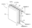
図2に示すように、水素含有ガス生成装置Pは、流体を処理する処理空間Sを形成する複数の扁平状の容器Bを横方向に積層状に並べ、それら複数の容器Bを容器並び方向に直交する方向での相対移動を許容する状態で前記容器並び方向両側から押し付け手段(図示省略)にて押し付けて構成されている。
前記容器Bは、図3ないし図5にも示すように、前記容器並び方向に位置する一対の容器形成部材51が、伝熱板52の両側に振り分ける状態で且つ周縁部分が伝熱板52に溶接接続される状態で形成されて、前記伝熱板52の両側に前記処理空間Sを備えるように構成されている。前記一対の容器形成部材51は、周辺部を接続代として内方部が膨出する形状に形成されている。
As shown in FIG. 2, the hydrogen-containing gas generation device P arranges a plurality of flat containers B forming a processing space S for processing a fluid in a laterally stacked manner, and arranges the plurality of containers B in a container arrangement direction. It is configured to be pressed by pressing means (not shown) from both sides of the container arrangement direction in a state that allows relative movement in a direction orthogonal to the container.
As shown in FIGS. 3 to 5, the container B is a state in which the pair of
前記複数の容器Bのうちの一部が、前記容器形成部材51の背部に積層状態で位置させる一つの皿状の補助容器形成部材53を、その周辺部を隣接するものの背部に溶接することにより、前記容器並び方向に複数の処理空間Sを形成する多処理空間型の容器Bmに構成されている。この多処理空間型の容器Bmを、図4及び図5に示す
又、前記複数の容器Bのうちの残部は、前記補助容器形成部材53を設けない基本型の容器Bsとされている。この基本型の容器Bsを図3に示す。
By welding one dish-shaped auxiliary
前記容器形成部材51、伝熱板52及び補助容器形成部材53は、夫々、ステンレス等の耐熱金属製であり、前記容器形成部材51及び補助容器形成部材53は、その耐熱金属からなる板材をプレス成形して形成される。
The
そして、前記複数の容器Bにて形成される複数の処理空間Sにより、前記脱硫、改質、変成、選択酸化、燃焼の各室1,3,4,5,6、前記蛇行状の蒸発処理流路2、及び、前記改質室加熱用、加熱用排ガス、冷却用排ガス、上流側熱交換用、脱硫後原燃料、下流側熱交換用、脱硫前原燃料用、排熱源排ガス、燃焼用燃料、燃焼用空気の各通流室7,8,9,10,11,12,13,14,15,16が構成されている。
この実施形態では、7個の容器Bを並べて、水素含有ガス生成装置Pが構成されている。
尚、7個の容器Bの区別が明確になるように、便宜上、容器を示す符合Bの後に、図2において左からの並び順を示す符合1,2,3……………7を付す。
そして、この実施形態では、左から2個目の容器B2、4個目の容器B4、右端の容器B7を基本型の容器Bsとしてある。
The desulfurization, reforming, modification, selective oxidation,
In this embodiment, the hydrogen-containing gas generator P is configured by arranging seven containers B.
In addition, in order to clarify the distinction of the seven containers B, for the sake of convenience,
In this embodiment, the second container B2, the fourth container B4, and the rightmost container B7 from the left are the basic containers Bs.
又、左端の容器B1は、一対の容器形成部材51のうち、左側の容器形成部材51の背部に前記補助容器形成部材53が設けられて、3個の処理空間Sを容器並び方向に並ぶ状態で備えた多処理空間型の容器Bmとされ、左から3個目の容器B3は、図4にも示すように、一対の皿状の容器形成部材51のうち、右側の容器形成部材51の背部に前記補助容器形成部材53が設けられて、3個の処理空間Sを容器並び方向に並ぶ状態で備えた多処理空間型の容器Bmとされ、左から5個目の容器B5は、図5にも示すように、一対の容器形成部材51の両方の背部夫々に前記補助容器形成部材53が設けられて、4個の処理空間Sを容器並び方向に並ぶ状態で備えた多処理空間型の容器Bmとされ、左から6個目の容器B6も、左から5個目の容器B5と同様に、4個の処理空間Sを容器並び方向に並ぶ状態で備えた多処理空間型の容器Bmとされている。
In the leftmost container B1, the auxiliary
図2に示すように、左端の容器B1(処理空間Sを3個備えた多処理空間型の容器Bm)において、左端の処理空間Sにて前記燃焼用燃料通流室15が構成され、中央の処理空間Sにて前記排熱源排ガス通流室14が構成され、右端の処理空間Sにて前記燃焼用空気通流室16が構成されて、この左端の容器B1にて前記エコノマイザEcが構成されている。
As shown in FIG. 2, in the leftmost container B1 (multi-processing space type container Bm having three processing spaces S), the combustion
左から2個目の容器B2(処理空間Sを前記容器並び方向に2個備えた基本型の容器Bs)における左側の処理空間Sにて前記加熱用排ガス通流室8が構成され、右側の処理空間Sにて前記蛇行状の蒸発処理流路2が構成されている。
この容器B2における蒸発処理流路2を形成する前記流路形成体56に当て付けた状態で、水蒸気生成用の補助加熱用電気ヒータ27が設けられている。
The exhaust
An
図3に基づいて、この容器B2について、説明を加える。尚、図3において、(イ)は容器B2の斜視図であり、(ロ)は容器B2の縦断側面図である。
前記一対の容器形成部材51のうちの一方は、蛇行状の膨出部56bを備えた流路形成体56に構成され、他方は、皿状の通流室形成体57に構成されている。
前記膨出部56bは、下方から上方に向けて蛇行状に延びるように流路形成体56に備えられ、その流路形成体56は、その周縁部分及び前記膨出部56bにおける隣接する膨出部分の間に相当する部分の夫々を溶接する状態で、前記伝熱板52に溶接接続されて、前記伝熱板52と前記流路形成体56の間に、下方から上方に向けて蛇行状に延びる前記蒸発処理流路2が形成される。
前記蒸発処理流路2内には、伝熱促進用のステンレスウール58が充填されている。
Based on FIG. 3, description is added about this container B2. 3A is a perspective view of the container B2, and FIG. 3B is a vertical side view of the container B2.
One of the pair of
The bulging
The evaporation
前記通流室形成体57は、その周縁部分を溶接する状態で、前記伝熱板52に溶接接続されて、前記伝熱板52と前記通流室形成体57との間に、前記加熱用排ガス通流室8が形成される。
更に、その加熱用排ガス通流室8内には、蛇行状の前記蒸発処理流路2に沿って燃焼排ガスを蛇行状に通流させるように、複数の邪魔板59が配設されている。
The flow
Further, a plurality of
図4にも示すように、左から3個目の容器B3(処理空間Sを前記容器並び方向に3個備えた多処理空間型の容器Bm)において、左端の処理空間Sにて前記燃焼室6が構成され、中央の処理空間Sにて前記改質室3が構成され、右端の処理空間Sにて前記改質室加熱用通流室7が構成されている。
そして、前記改質室3を構成する処理空間S内に、炭化水素系の原燃料ガスを水蒸気を用いて水素ガスを主成分とするガスに改質処理するルテニウム、ニッケル、白金等の改質反応用触媒19が充填されている。
As shown also in FIG. 4, in the third container B3 from the left (multi-processing space type container Bm provided with three processing spaces S in the container arrangement direction), the combustion chamber in the leftmost
Then, in the processing space S constituting the reforming
前記改質室3は、原燃料ガスと水蒸気とが混合状態で上端部から供給されて、下方側に向けて流動するように構成され、その改質室3として構成される処理空間Sと前記改質室加熱用通流室7として構成される処理空間Sとを仕切る皿状の容器形成部材51の下端部には、容器並び方向に隣接するそれら処理空間Sを連通する流体通過部54が設けられて、その流体通過部54を通して、前記改質室3にて改質処理された改質処理ガスを前記改質室加熱用通流室7に流入させるように構成されている。
そして、前記改質室3の下端部分(即ち、改質処理ガスの出口部分)における改質反応用触媒19の温度を検出するように改質温度センサTrが設けられている。
The reforming
A reforming temperature sensor Tr is provided so as to detect the temperature of the reforming
ちなみに、前記改質室3では、原燃料ガスがメタンガスを主成分とする天然ガスベースの都市ガス(13A)である場合は、改質反応用触媒19の触媒作用により、例えば600〜750°Cの範囲の改質処理温度の下で、メタンガスと水蒸気とを改質反応させて、水素ガスを主成分とする改質処理ガスを生成させる。
Incidentally, in the reforming
又、左から3個目の容器B3の左端の処理空間Sにて構成される燃焼室6内における下端部に、その燃焼室6内にて燃焼用燃料を燃焼させるように、前記改質用バーナ17が設けられている。
この改質用バーナ17は、図4にも示すように、複数の第1噴出孔17aを長手方向に並べて列状に備えた第1噴出管17Aと複数の第2噴出孔17bを長手方向に並べて列状に備えた第2噴出管17Bとを第1噴出孔17aの噴出方向と第2噴出孔17bの噴出方向とが交差するように並べて設けて構成されている。
更に、燃焼室6内における改質バーナ17よりも上方側に、白金、パラジウム等から成る燃焼触媒を保持させた燃焼触媒保持体18が配設されている。
In addition, the reforming fuel is burned in the
As shown in FIG. 4, the reforming
Further, a combustion catalyst holding body 18 holding a combustion catalyst made of platinum, palladium or the like is disposed above the reforming
前記改質バーナ17に着火して改質室3を改質処理可能な温度に加熱する起動時は、改質室3に供給するのと同様の原燃料ガスを燃焼用燃料として燃焼用空気と混合させた状態で第1噴出管17Aに供給して燃焼させるように構成され、前記燃料電池Gの燃料極から排出された排燃料ガスとしてのオフガスを燃焼用燃料として燃焼させる通常時は、そのオフガスを第2噴出管17Bに供給し且つ燃焼用空気を第1噴出管17Aに供給するように構成されている。
又、前記改質室3を改質処理可能なように加熱するには、オフガスだけでは不足する場合、その不足分を補うように、原燃料ガスを燃焼用燃料として、燃焼用空気に混合させた状態で、第1噴出管17Aに追加供給するように構成されている。
At the time of startup in which the reforming
In addition, in order to heat the reforming
左から4個目の容器B4(基本型の容器Bs)における左側の処理空間Sにて前記上流側熱交換用通流室10が構成され、右側の処理空間Sにて前記脱硫後原燃料通流室11が構成され、この左から4個目の容器B4にて、前記脱硫後原燃料用熱交換器Eaが構成されている。尚、この脱硫後原燃料用熱交換器Eaを構成する容器B4は、一対の容器形成部材51の両方が皿状である。
この脱硫後原燃料用熱交換器Eaを構成する左から4個目の容器B4の右側の容器形成部材51に当て付けた状態で、起動用電気ヒータ28が設けられている
The upstream heat
The starting
図5にも示すように、左から5個目の容器B5(処理空間Sを前記容器並び方向に4個備えた多処理空間型の容器Bm)において、左端及び左から2個目の処理空間Sの夫々は、炭化水素系の原燃料ガスを脱硫処理する脱硫反応用触媒20を充填して脱硫室1に構成され、左から3個目の処理空間Sは、脱硫前原燃料通流室13に構成され、右端の処理空間Sは、一酸化炭素ガスを水蒸気を用いて二酸化炭素ガスに変成処理する酸化鉄系又は銅亜鉛系の変成反応用触媒21を充填して変成室4に構成されている。
ちなみに、詳細は後述するが、この左から5個目の容器B5にて構成する変成室4を1段目として、変成室4を4段に設けるので、以下、この左から5個目の容器B5にて構成する変成室4を1段目の変成室4と記載する場合がある。
As shown also in FIG. 5, in the fifth container B5 from the left (multi-processing space type container Bm having four processing spaces S in the container arrangement direction), the second processing space from the left end and the left. Each of S is filled with a desulfurization reaction catalyst 20 for desulfurizing a hydrocarbon-based raw fuel gas to constitute a
Incidentally, although details will be described later, since the
又、左端の処理空間Sと左から2個目の処理空間Sとを仕切る皿状の容器形成部材51、左から2個目の処理空間Sと左から3個目の処理空間Sとを仕切る伝熱板52の夫々に、夫々の両側の処理空間Sを連通する流体通過部54が設けられている。そして、左から2個目の処理空間Sにて構成する脱硫室1を1段目とし、左端の処理空間Sにて構成する脱硫室1を2段目として、脱硫対象の原燃料ガスを、脱硫前原燃料通流室13を通過させて予熱した後、1段目、2段目の順に各脱硫室1を通流させて、脱硫処理するように構成されている。
In addition, the dish-shaped
又、脱硫前原燃料通流室13を構成する左から3個目の処理空間Sと1段目の変成室4を構成する右端の処理空間Sとを仕切る皿状の容器形成部材51を、伝熱壁として、その伝熱壁を通して、脱硫前原燃料通流室13を通流する脱硫対象の原燃料ガスと1段目の変成室4を通流する変成処理対象の改質処理ガスとを熱交換させるように構成されている。
つまり、1段目の変成室4が前記下流側熱交換用通流室12として兼用するように構成されて、前記脱硫前原燃料通流室13と下流側熱交換用通流室12とにより、前記脱硫前原燃料用熱交換器Ebが構成されている。
この左から5個目の容器B5における前記変成室4を形成する補助容器形成部材53に当て付けた状態で、変成処理用の起動用電気ヒータ29が設けられている。
Further, a dish-like
That is, the first-
A start-up electric heater 29 for transformation processing is provided in a state of being applied to the auxiliary
左から6個目の容器B6(処理空間Sを前記容器並び方向に4個備えた多処理空間型の容器Bm)において、左端の処理空間Sは前記冷却用排ガス通流室9に構成され、左から2個目、左から3個目及び右端の処理空間Sの夫々は、前記変成反応用触媒21を充填して変成室4に構成されている。
In the sixth container B6 from the left (multi-processing space type container Bm having four processing spaces S in the container arrangement direction), the leftmost processing space S is configured in the cooling exhaust
又、左から2個目の処理空間Sと左から3個目の処理空間Sを仕切る伝熱板52、左から3個目の処理空間Sと右端の処理空間Sとを仕切る皿状の容器形成部材51夫々に、夫々の両側の処理空間Sを連通する流体通過部54が設けられている。そして、左から2個目の処理空間Sにて構成する変成室4を2段目とし、左から3個目の処理空間Sにて構成する変成室4を3段目とし、右端の処理空間Sにて構成する変成室4を4段目として、前記左から5個目の容器B5にて構成する1段目の変成室4からこの2段目の変成室4に外部のガス処理流路32にて改質処理ガスを供給して、改質処理ガスを2段目、3段目、4段目の順に各変成室4を通流させて、変成処理するように構成されている。
4段目の変成室4の下端部分(即ち、改質処理ガスの出口部分)における変成触媒の温度を検出するように変成温度センサTsが設けられている。
又、この左から6個目の容器B6における4段目の変成室4を形成する補助容器形成部材53に当て付けた状態で、変成処理用の起動用電気ヒータ30が設けられている。
Further, a
A shift temperature sensor Ts is provided so as to detect the temperature of the shift catalyst at the lower end portion of the fourth shift chamber 4 (that is, the outlet portion of the reforming process gas).
In addition, a starter
ちなみに、前記変成室4では、変成反応用触媒21の触媒作用により、改質室3から供給される改質処理ガス中の一酸化炭素と水蒸気とを、例えば、150〜400°Cの範囲の変成処理温度の下で変成反応させる。
Incidentally, in the
左から7個目、即ち右端の容器B7(基本型の容器Bs)において、左側の処理空間Sは何にも用いずに伝熱調整用とされ、右側の処理空間Sは、一酸化炭素ガスを選択的に酸化処理する白金、ルテニウム、ロジウム等の貴金属系の選択酸化用触媒22を充填して前記選択酸化室5に構成されている。
In the seventh container from the left, that is, the rightmost container B7 (basic container Bs), the left processing space S is used for heat transfer adjustment without any use, and the right processing space S is carbon monoxide gas. The
この選択酸化室5は、前記変成室4にて変成処理された改質処理ガスと選択酸化用空気が混合状態で下端部から供給されて、上方側に向けて流動して上端部から排出するように構成され、選択酸化室5における上下方向略中央部の選択酸化触媒22の温度を検出するように、選択酸化温度センサTmが設けられている。
The
ちなみに、前記選択酸化室5では、選択酸化反応用触媒22の触媒作用により、例えば80〜150°Cの選択酸化処理温度の下で、変成処理後の改質処理ガス中に残存している一酸化炭素ガスが選択酸化される。
Incidentally, in the
尚、容器Bの処理空間Sに、前記改質反応用触媒19等の触媒を充填する場合は、扁平状の容器Bを上下方向に沿わせた姿勢で、処理空間Sにおける底部よりもやや上方部にて触媒を受けるべく、多孔状の触媒受け板55を、その処理空間Sを形成する容器形成部材51、伝熱板52又は皿状の補助容器形成部材53に溶接にて取り付けられている。
When the processing space S of the container B is filled with a catalyst such as the reforming
そして、上述の7個の扁平状の容器Bを、夫々を上下方向に沿わせた姿勢で、左端の容器B1の外側、左端の容器B1と左から2個目の容器B2との間、左から2個目の容器B2と左から3個目の容器B3との間、左から3個目の容器B3と左から4個目の容器B4との間、左から4個目の容器B4と左から5個目の容器B5との間、及び、左から5個目の容器B5と左から6個目の容器B6との間の夫々に伝熱係数設定用の断熱材23を配置した状態で密接状態に並べて設けて、前記押し付け手段により、それら密接状態の7個の容器Bを容器並び方向に直交する方向での相対移動を許容する状態で容器並び方向両側から押し付けるように構成し、更に、前記選択酸化室5を構成する右端の容器B7の側方に、その容器B7に向けて通風するように冷却用送風機26を設けて、その冷却用送風機26により、前記選択酸化室5を冷却するように構成されている。つまり、前記冷却用送風機26により、前記選択酸化室5を冷却する冷却手段が構成される。
Then, in the posture in which the above-described seven flat containers B are arranged in the vertical direction, the left side of the left end container B1 and the left end container B1 and the second container B2 from the left, Between the second container B2 and the third container B3 from the left, between the third container B3 from the left and the fourth container B4 from the left, and the fourth container B4 from the left A state in which the heat transfer coefficient setting
つまり、脱硫室1、改質室3、変成室4及び選択酸化室5のうち、改質室3が最も高温に維持する必要があり、選択酸化室5が最も低温に維持する必要がある。
そこで、改質室3とそれを加熱する燃焼室6とが伝熱可能に密接して設けられ、その密接状態の改質室3及び燃焼室6における改質室3側に、脱硫室1、変成室4、選択酸化室5が記載順に改質室3の側から並んで位置し且つ隣接するもの同士で熱伝導可能に設けられ、密接状態の改質室3及び燃焼室6における燃焼室6側に、蒸発処理流路2が燃焼室6から熱伝導可能に設けられている。
That is, among the
Therefore, the reforming
そして、前記運転制御部Cが、前記改質温度センサTrにて検出される改質室3の温度が改質処理用設定温度になるように前記改質バーナ17の燃焼量を調節し、且つ、前記選択酸化温度センサTmにて検出される選択酸化室5の温度が選択酸化用設定温度になるように前記冷却用送風機26の通風量を調節して冷却量を調節するように構成されている。
このように、前記改質室3の温度が前記改質処理用設定温度になるように前記改質バーナ17の燃焼量が調節され、且つ、前記選択酸化室5の温度が前記選択酸化用設定温度になるように前記冷却用送風機26の通風量が調節される状態で、並びに、変成室4が冷却用排ガス通流室9を通流する燃焼排ガスにて冷却される状態で、改質室3と選択酸化室5との間に位置する脱硫室1及び変成室4夫々の温度が脱硫処理可能な温度、変成処理可能な温度になり、且つ、蒸発処理流路2が水蒸気生成可能な温度になるように、隣接するもの同士、即ち、改質室3と脱硫室1との間、脱硫室1と変成室4との間、変成室4と選択酸化室5との間、及び、燃焼室6と蒸発処理流路2との間の夫々の伝熱係数が所定に設定されている。
The operation control unit C adjusts the combustion amount of the reforming
Thus, the combustion amount of the reforming
以下、各容器Bにて形成される各処理空間Sに流体を供給したり、各処理空間Sから流体を排出するための、各処理空間Sに対する流路の接続形態について説明する。尚、各処理空間Sにおいては、流体を上部から供給して下方側に向けて通流させて下部から排出する、あるいは、流体を下部から供給して上方側に向けて通流させて上部から排出するように、流体を上下方向に通流させるように構成するので、各流路は、各処理空間Sの上端部又は下端部に接続する。 Hereinafter, the connection form of the flow path to each processing space S for supplying the fluid to each processing space S formed in each container B and discharging the fluid from each processing space S will be described. In each processing space S, the fluid is supplied from the upper part and flows downward and discharged from the lower part, or the fluid is supplied from the lower part and flows upward and supplied from the upper part. Since the fluid is configured to flow in the vertical direction so as to be discharged, each flow path is connected to the upper end portion or the lower end portion of each processing space S.
発電用原燃料供給路31が前記脱硫前原燃料通流室13に接続され、前記2段目の脱硫室1と前記脱硫後原燃料通流室11とが、その脱硫後原燃料通流室11と前記改質室3とが、前記改質室加熱用通流室7と前記上流側熱交換用通流室10とが、その上流側熱交換用通流室10と前記下流側熱交換用通流室12を兼用する前記1段目の変成室4とが、その1段目の変成室4と前記2段目の変成室4とが、前記4段目の変成室4と前記選択酸化室5とが、夫々、ガス処理流路32にて接続され、更に、その選択酸化室5と燃料電池Gの燃料ガス供給部とが燃料ガス流路33にて接続されている。
A power generation raw
前記発電用原燃料供給路31には、改質処理用の原燃料ガスの供給を断続する発電用原燃料断続弁V1、及び、改質処理用の原燃料ガスの供給量を調節する発電用原燃料調節弁V2が設けられている。
2段目の脱硫室1と前記脱硫後原燃料通流室11とを接続するガス処理流路32には、脱硫後の原燃料ガスに水蒸気を混合させるためのエジェクタ35が設けられている。
The power generation raw
In the gas
又、前記4段目の変成室4と前記選択酸化室5とを接続するガス処理流路32には、選択酸化用送風機24から選択酸化用空気が供給される選択酸化用空気供給路25が接続されて、変成室4にて変成処理された改質処理ガスに選択酸化用空気を混合させて前記選択酸化室5に供給するように構成されている。
In addition, a selective oxidation
つまり、原燃料ガスを1段目、2段目の脱硫室1にて脱硫処理し、その脱硫処理した原燃料ガスに、後述する蒸発処理流路2から水蒸気流路34にて供給される水蒸気をエジェクタ35にて混合させ、その水蒸気を混合させた原燃料ガスを改質室3にて改質処理し、その改質処理ガスを1段目、2段目、3段目、4段目の変成室4にて変成処理し、その変成処理した改質処理ガスを選択酸化室5にて選択酸化処理して、一酸化炭素濃度の低い水素含有ガスを生成し、その水素含有ガスを燃料ガスとして燃料ガス流路33を通じて燃料電池Gに供給するように構成されている。
That is, the raw fuel gas is desulfurized in the first-stage and second-
前記燃焼室6と前記加熱用排ガス通流室8とが、その加熱用排ガス通流室8と前記冷却用排ガス通流室9とが、その冷却用排ガス通流室9と前記エコノマイザEcの前記排熱源排ガス通流室14とが、夫々、燃焼排ガス流路37にて接続されて、燃焼室6から排出される燃焼排ガスを、加熱用排ガス通流室8、冷却用排ガス通流室9、エコノマイザEcの排熱源排ガス通流室14の順に通流させるように構成されている。
The
前記燃料電池Gの前記燃料極から排出されるオフガスを前記改質バーナ17にて燃焼させる燃焼用燃料として導くオフガス路38にて、その燃料電池Gのオフガス排出部と前記エコノマイザEcの燃焼用ガス通流室15とが、その燃焼用ガス通流室15と前記改質バーナ17の第2噴出管17Bとが、夫々接続されている。
前記燃料ガス流路33と前記オフガス路38とを前記燃料電池Gを迂回して接続するバイパス路60が設けられ、前記燃料ガス流路33における前記オフガス路38の接続箇所よりも前記燃料電池Gの側の箇所に、その燃料電池Gへの燃料ガスの供給を断続する燃料ガス断続弁V5が設けられ、前記バイパス路60には、そのバイパス路60を開閉するバイパス開閉弁V6が設けられ、前記オフガス路38における前記バイパス路60の接続箇所よりも上流側の箇所に電池下流側開閉弁V7が設けられている。
In an off
A
又、前記改質バーナ17に燃焼用空気を供給する燃焼用送風機39と前記エコノマイザEcの前記燃焼用空気通流室16とが、その燃焼用空気通流室16と前記改質バーナ17の第1噴出管17Aとが、夫々燃焼用空気流路40にて接続されている。
A
そして、前記エコノマイザEcにて、燃焼排ガスの排熱をオフガス及び燃焼用空気に回収して、それらオフガス及び燃焼用空気を予熱し、そのように予熱したオフガス及び燃焼用空気を前記改質バーナ17に供給して燃焼させるように構成されている。
Then, the economizer Ec recovers the exhaust heat of the combustion exhaust gas into off-gas and combustion air, pre-heats the off-gas and combustion air, and converts the pre-heated off-gas and combustion air into the reforming
更に、前記改質バーナ17の第1噴出管17Aには、原燃料ガスを燃焼用燃料として供給するバーナ用原燃料供給路41が接続されている。
このバーナ用原燃料供給路41には、前記改質バーナ17への原燃料ガスの供給を断続するバーナ用原燃料断続弁V3、及び、このバーナ用原燃料供給路41を通して供給する原燃料ガスの供給量を調節するバーナ用原燃料調節弁V4が設けられている。
尚、前記バーナ用原燃料供給路41と前記燃焼用空気流路40とは、前記第1噴出管17Aの手前で合流させた状態でその第1噴出管17Aに接続され、原燃料ガスを燃焼用空気と予混合した状態で第1噴出管17Aに供給するように構成されている。
Further, a burner raw
The burner raw
The burner raw
前記改質用水タンク44内の改質用水を改質用水ポンプ42にて供給する改質用水供給流路43が前記蒸発処理流路2の下端に接続され、前記加熱用排ガス通流室8による加熱により前記蒸発処理流路2にて生成された水蒸気を導く前記水蒸気流路34が前記エジェクタ35に接続されている。
A reforming
前記1段目予熱用熱交換器46は、前記改質用水供給流路43を通流する改質用水と前記燃料ガス流路33を通流する燃料ガスとを熱交換させるように設けられ、前記バイパス路60には、通流する気体から凝縮水を除去するドレイントラップ48が設けられている。
前記2段目予熱用熱交換器47は、前記改質用水供給流路43における前記1段目予熱用熱交換器46よりも下流側の箇所を通流する改質用水と、前記4段目の変成室4と前記選択酸化室5とを接続するガス処理流路32を通流する改質処理ガスとを熱交換させるように設けられている。
更に、前記改質用水供給流路43における前記2段目予熱用熱交換器47よりも下流側の箇所に蛇行状流路部分43dが設けられ、この蛇行状流路部分43dが、左から3個目の容器B3における前記燃焼室6を形成する容器形成部材51に熱伝導可能に当て付けて設けられて、容器形成部材51からの伝導熱及び輻射熱により改質用水供給流路43を通流する改質用水を予熱するように構成されている。
つまり、改質用水が、前記1段目予熱用熱交換器46、前記2段目予熱用熱交換器47、前記蛇行状流路部分43dにて予熱された後、前記蒸発処理流路2に供給されるように構成されている。
The first stage preheating
The second stage preheating
Further, a meandering
That is, the reforming water is preheated in the first-stage
更に、前記4段目の変成室4と前記選択酸化室5とを接続するガス処理流路32における前記2段目予熱用熱交換器37よりも下流側の箇所には、排熱回収用熱交換器49が設けられている。
図示は省略するが、前記燃料電池Gから発生する熱により貯湯する貯湯タンクが設けられ、この貯湯タンクの湯水を循環させる湯水循環路に設けられた加熱用熱交換器に前記燃料電池Gを冷却した冷却水を通流させることにより、前記貯湯タンクの湯水を加熱するように構成されている。
そして、前記排熱回収熱交換器49が前記湯水循環路に設けられ、ガス処理流路32を通流する改質処理ガスの排熱を回収して、前記湯水循環路を通流する湯水を加熱するように構成されている。
Further, in the gas
Although not shown, a hot water storage tank for storing hot water by heat generated from the fuel cell G is provided, and the fuel cell G is cooled by a heating heat exchanger provided in a hot water circulation path for circulating hot water in the hot water storage tank. The hot water in the hot water storage tank is heated by allowing the cooling water to flow therethrough.
The exhaust heat
前記4段目の変成室4と前記選択酸化室5とを接続するガス処理流路32における前記排熱回収用熱交換器49よりも下流側の箇所に、改質処理ガスから凝縮水を除去するドレイントラップ50が設けられている。
前記燃料ガス流路33に設けられたドレイントラップ48にて除去された凝縮水は、凝縮水回収路61を通して前記改質用水タンク44に供給され、前記4段目の変成室4と前記選択酸化室5とを接続するガス処理流路32に設けられたドレイントラップ50にて除去された凝縮水は凝縮水回収路62を通して前記改質用水タンク44に供給されるように構成されている。
又、図示を省略するが、前記燃料電池Gの酸素極から排出された排空気に含まれる水蒸気を凝縮させた凝縮水や、前記エコノマイザEcの排熱源排ガス通流室14を通過した燃焼排ガスに含まれる水蒸気を凝縮させた凝縮水も前記改質用水タンク44に供給されるように構成されている。
つまり、上述のように改質処理ガス、燃料ガス、排空気及び燃焼排ガス等から回収した凝縮水を前記改質用水タンク44に貯留して、その貯留している凝縮水を改質用水として用いるように構成されている。
Condensed water is removed from the reforming process gas at a location downstream of the exhaust heat
Condensed water removed by the
Although not shown, the condensed water obtained by condensing water vapor contained in the exhaust air discharged from the oxygen electrode of the fuel cell G or the combustion exhaust gas that has passed through the exhaust heat source exhaust
That is, as described above, the condensed water recovered from the reforming gas, fuel gas, exhaust air, combustion exhaust gas, and the like is stored in the reforming
次に、前記運転制御部Cによる制御動作を説明する。
この運転制御部Cは、電気負荷に追従するように前記燃料電池Gの発電電力を調節する通常運転時においては、前記改質温度センサTrの検出温度が改質処理用設定温度になるように、バーナ用原燃料調節弁V4を調節して前記改質バーナ17の燃焼量を調節し、且つ、前記改質バーナ17へ設定空燃比となる量の燃焼用空気を供給するように、燃焼用送風機39の回転速度を調節する改質室温度制御、選択酸化温度センサTmの検出温度が選択酸化用設定温度になるように、冷却用送風機26の回転速度を調節する選択酸化室温度制御、前記燃料電池Gの発電電力を電気負荷に応じて調節するように、原燃料ガスの供給量を調節すべく前記発電用原燃料調節弁V2を制御する発電電力調節制御、並びに、S/C(原燃料ガスに対する水蒸気の量の比である水蒸気/炭素比に相当する)を目標S/Cになるように、改質用水の供給量を調節すべく前記改質用水ポンプ42の回転速度を制御するS/C調節制御を実行する。
Next, the control operation by the operation control unit C will be described.
In the normal operation in which the operation control unit C adjusts the generated power of the fuel cell G so as to follow the electric load, the detected temperature of the reforming temperature sensor Tr is set to the reforming processing set temperature. The burner raw fuel control valve V4 is adjusted to adjust the combustion amount of the reforming
ちなみに、燃料電池Gにおける燃料利用率は予め設定されており、前記発電用原燃料調節弁V2及び前記バーナ用原燃料調節弁V4の制御情報に基づいて、改質バーナ17に供給されるオフガスと原燃料ガスを合わせた燃焼用燃料の量を求めることができる。
従って、運転制御部Cは、前記改質室温度制御においては、現時点の改質バーナ17への燃焼用燃料の供給量(オフガスと原燃料ガスを合わせた量)を求めて、その求めた燃焼用燃料の供給量に対して設定空燃比となる量の燃焼用空気を供給するように、前記燃焼用送風機39の回転速度を調節するように構成されている。
Incidentally, the fuel utilization rate in the fuel cell G is set in advance, and the off-gas supplied to the reforming
Therefore, in the reforming chamber temperature control, the operation control unit C obtains the current amount of combustion fuel supplied to the reforming burner 17 (a total amount of off-gas and raw fuel gas) and obtains the obtained combustion. The rotational speed of the
ちなみに、前記改質処理用設定温度は、例えば600〜750°Cの範囲に設定され、前記選択酸化用設定温度は、例えば、80〜150°Cの範囲に設定される。又、前記設定空燃比は、前記改質バーナ17を適切に燃焼させることができる空燃比に設定されている。
Incidentally, the set temperature for reforming treatment is set in a range of 600 to 750 ° C., for example, and the set temperature for selective oxidation is set in a range of 80 to 150 ° C., for example. The set air-fuel ratio is set to an air-fuel ratio that allows the reforming
そして、運転制御部Cは、通常運転時において、前記変成温度センサTsにて検出される変成室4の温度(以下、変成室温度と記載する場合がある)が変成処理用の設定適正範囲よりも高くなると、S/Cを大きくするように改質用水の供給量を増大調節すべく、前記改質用水供給部Jの作動を制御する(具体的には、前記改質用水ポンプ42の回転速度を調節する)ように構成されている。
具体的には、運転制御部Cは、前記S/C調節制御において、前記変成温度センサTsにて検出される変成室温度が設定適正範囲内のとき、及び、変成室温度が設定適正範囲よりも高くなってもその設定適正範囲よりも高い状態の継続時間が設定時間以内のときは、前記目標S/Cを通常S/Cに設定し、前記変成温度センサTsにて検出される変成室温度が設定適正範囲よりも高い状態の継続時間が前記設定時間を越えると、前記目標S/Cを増大補正S/Cに設定して、その設定した目標S/Cになるように改質用水の供給量を調節すべく、前記改質用水ポンプ42の回転速度を調節するように構成されている。
ちなみに、前記設定適正範囲は例えば150〜400°Cに設定され、前記設定時間は例えば1分間程度に設定される。
又、前記通常S/Cは、改質室3への原燃料ガス供給量(炭素のモル数)に対する水蒸気供給量(モル数)の比にて、例えば、2.8程度に設定され、前記補正S/Cは、前記設定S/Cよりも例えば0.2程度大きくなるように設定されている。
Then, the operation control unit C detects that the temperature of the
Specifically, the operation control unit C, in the S / C adjustment control, when the shift chamber temperature detected by the shift temperature sensor Ts is within the set appropriate range, and the shift chamber temperature is lower than the set proper range. If the duration of the state higher than the set appropriate range is within the set time even if the value is higher, the target S / C is set to normal S / C and the shift chamber detected by the shift temperature sensor Ts When the duration time during which the temperature is higher than the set appropriate range exceeds the set time, the target S / C is set to the increase correction S / C, and the reforming water is set to the set target S / C. In order to adjust the supply amount, the rotational speed of the reforming
Incidentally, the set appropriate range is set to 150 to 400 ° C., for example, and the set time is set to about 1 minute, for example.
Further, the normal S / C is set to, for example, about 2.8 in the ratio of the amount of water vapor supply (number of moles) to the amount of raw fuel gas supplied to the reforming chamber 3 (number of moles of carbon). The correction S / C is set to be, for example, about 0.2 larger than the setting S / C.
次に、図6及び図7に基づいて、前記運転制御部Cによる制御動作を説明する。
図6のフローチャートに示すように、前記運転制御部Cは、起動タイミングになると、改質バーナ17の燃焼を開始して、改質室3を改質処理可能な温度に加熱してその改質室3での原燃料ガスの改質処理を開始する起動運転処理を実行し、その起動運転処理が終了すると、電気負荷に追従するように前記燃料電池Gの発電電力を調節する通常運転処理を実行し、停止タイミングになると、前記脱硫室1、前記改質室3、前記変成室4及び前記選択酸化室5並びにそれらを接続するガス処理流路32に原燃料ガスを充填して水素含有ガス生成部Pの運転を停止する停止処理を実行する。
例えば、燃料電池発電装置を1日のうちの所定の運転時間帯に運転する場合は、その運転時間帯の開始時刻になると起動タイミングとなり、その運転時間帯の終了時刻になると停止タイミングになる。
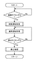
Next, based on FIG.6 and FIG.7, the control action by the said operation control part C is demonstrated.
As shown in the flowchart of FIG. 6, at the start timing, the operation control unit C starts combustion of the reforming
For example, when the fuel cell power generator is operated during a predetermined operation time zone of the day, the start timing is reached at the start time of the operation time zone, and the stop timing is reached at the end time of the operation time zone.
前記起動運転処理における制御動作について説明を加える。
前記起動タイミングになると、前記燃料ガス断続弁V5及び電池下流側開閉弁V7を閉弁し、且つ、前記バイパス開閉弁V6を開弁して、後述する停止処理により、前記改質室3、前記変成室4及び前記選択酸化室5並びにそれらを接続するガス処理流路32に充填されていた原燃料ガスが前記改質バーナ17に供給される状態とし、続いて、前記燃焼用送風機39の作動を開始し且つバーナ用原燃料断続弁V3を開弁して、イグナイタ(図示省略)を作動させることにより、前記改質バーナ17の燃焼を開始させ、並びに、前記補助加熱用電気ヒータ27、前記起動用電気ヒータ28,29,30の加熱作動を開始する。
A description will be given of the control operation in the startup operation process.
At the start timing, the fuel gas intermittent valve V5 and the battery downstream side open / close valve V7 are closed, and the bypass open / close valve V6 is opened, and the reforming
続いて、改質温度センサTrにて検出される改質室温度が改質用水供給開始用設定温度以上になると、前記改質用水ポンプ42の作動を開始して、前記蒸発処理流路2への改質用水の供給を開始する。すると、蒸発処理流路2にて生成された水蒸気が改質室3に供給されて、停止時に前記改質室3、前記変成室4、前記選択酸化室5及びそれらを接続するガス処理流路32、並びに、前記燃料電池G及び燃料ガス流路33に充填されていた原燃料ガスが水蒸気により押し出されて、前記改質バーナ17に供給される。
続いて、前記改質温度センサTrにて検出される改質室温度が原燃料供給開始用設定温度以上になると、前記発電用原燃料断続弁V1を開弁して、前記脱硫室1への原燃料ガスの供給を開始し、且つ、前記選択酸化用送風機29の作動を開始して、選択酸化用空気の供給を開始する。
続いて、待機用設定時間が経過すると、前記燃料ガス断続弁V5及び電池下流側開閉弁V7を開弁し、且つ、前記バイパス開閉弁V6を閉弁して、前記燃料電池Gへの燃料ガスの供給を開始する。
以降は、前記燃料電池Gの燃料極から排出されたオフガスが燃焼用燃料として前記改質バーナ17に供給される。
Subsequently, when the reforming chamber temperature detected by the reforming temperature sensor Tr becomes equal to or higher than the reforming water supply start set temperature, the reforming
Subsequently, when the reforming chamber temperature detected by the reforming temperature sensor Tr becomes equal to or higher than the raw fuel supply start set temperature, the power generation raw fuel intermittent valve V1 is opened to supply the
Subsequently, when the set time for standby elapses, the fuel gas intermittent valve V5 and the battery downstream side open / close valve V7 are opened, and the bypass open / close valve V6 is closed to supply the fuel gas to the fuel cell G. Start supplying.
Thereafter, off-gas discharged from the fuel electrode of the fuel cell G is supplied to the reforming
前記改質用水供給開始用設定温度は、原燃料ガスの熱分解を防止でき且つ水蒸気の凝縮を防止できる温度、例えば220〜250°Cに設定され、前記原燃料開始用設定温度は、原燃料ガスの改質処理が可能な温度、例えば、600°Cに設定されている。
又、前記待機用設定時間は、前記脱硫室1への原燃料ガスの供給を開始してから、改質室3における改質処理、変成室4における変成処理及び選択酸化室5における選択酸化処理が安定するのに要する時間に設定される。
The reforming water supply starting set temperature is set to a temperature that can prevent thermal decomposition of raw fuel gas and condensation of water vapor, for example, 220 to 250 ° C., and the raw fuel starting set temperature is The temperature at which gas reforming can be performed, for example, 600 ° C. is set.
Further, the set time for standby is the start of the supply of the raw fuel gas to the
図7に示すフローチャートに基づいて、前記通常運転処理の制御動作について説明を加える。
運転制御部Cは、上述した改質室温度制御、選択酸化室温度制御及び発電電力調節制御を実行し(ステップ#1〜3)、続いて、前記変成温度センサTsにて検出される変成室温度が設定適正範囲内のとき(ステップ#4)、及び、変成室温度が設定適正範囲よりも高くなってもその設定適正範囲よりも高い状態の継続時間が設定時間以内のときは(ステップ#4,5)、前記目標S/Cを通常S/Cに設定し(ステップ#6)、前記変成温度センサTsにて検出される変成室温度が設定適正範囲よりも高い状態の継続時間が前記設定時間を越えると(ステップ#4,5)、前記目標S/Cを増大補正S/Cに設定して(ステップ#7)、その設定した目標S/Cになるように改質用水の供給量を調節すべく、前記改質用水ポンプ42の回転速度を調節する(ステップ#8)。
Based on the flowchart shown in FIG. 7, the control operation of the normal operation process will be described.
The operation control unit C executes the above-described reforming chamber temperature control, selective oxidation chamber temperature control, and generated power adjustment control (
前記停止処理における制御動作について説明を加える。
前記停止タイミングになると、前記改質用水ポンプ42の作動を継続した状態で、前記燃料ガス断続弁V5及び電池下流側開閉弁V7の開弁状態を維持し、前記バイパス開閉弁V6を開弁し、並びに、前記発電用原燃料断続弁V1を閉弁して前記脱硫部1への原燃料ガスの供給を停止する。
この状態では、蒸発処理流路2への改質用水の供給が継続されているので、その蒸発処理流路2にて生成された水蒸気が前記改質室3に供給され、その改質室3、変成室4、選択酸化室5及びそれらを接続するガス処理流路32に残留していた改質処理ガス、並びに、燃料電池G及び燃料ガス流路33に残留していた燃料ガスが改質バーナ17に供給されて燃焼し、改質室3、変成室4、選択酸化室5及びにそれらを接続するガス処理流路32、並びに、燃料電池G及び燃料ガス流路33に水蒸気が満たされる。
The control operation in the stop process will be described.
At the stop timing, while the operation of the reforming
In this state, since the supply of the reforming water to the evaporation
続いて、前記改質温度センサTrにて検出される改質室温度がパージ用設定温度に低下すると、前記改質用水ポンプ42の作動を停止し、且つ、前記発電用原燃料断続弁V1を開弁することにより、前記脱硫室1に原燃料ガスを供給して、改質室3、変成室4、選択酸化室5及びそれらを接続するガス処理流路32、並びに、燃料電池G及び燃料ガス流路33に満たされていた水蒸気を排出して、脱硫室1、改質室3、変成室4、選択酸化室5及びそれらを接続するガス処理流路32、並びに、燃料電池G及び燃料ガス流路33に原燃料ガスを満たし、予め設定されたパージ用設定時間が経過すると、前記バイパス開閉弁V6及び電池下流側開閉弁V7を閉弁し、続いて、前記発電用原燃料断続弁V1を閉弁して、脱硫室1、改質室3、変成室4、選択酸化室5及びそれらを接続するガス処理流路32、並びに、燃料電池G及び燃料ガス流路33に原燃料ガスを充填する。
前記パージ用設定温度は、原燃料ガスの熱分解を防止でき且つ水蒸気の凝縮を防止できる温度、例えば、400°Cに設定される。
Subsequently, when the reforming chamber temperature detected by the reforming temperature sensor Tr falls to the purge setting temperature, the operation of the reforming
The purge set temperature is set to a temperature at which raw fuel gas can be prevented from thermal decomposition and water vapor can be prevented from condensing, for example, 400 ° C.
以下、図8に基づいて、上述のように前記変成温度センサTsにて検出される変成室温度が設定適正範囲よりも高くなるとS/Cを大きくすることにより、変成室温度を低下させることができることを検証した結果を説明する。
尚、図8において、細い実線にて、前記変成温度センサTsにて検出される変成室温度の経時変化を示し、太い実線にて、S/Cの経時変化を示す。
図8に示すように、S/Cを2.8から3.0に増大変更すると、変成室温度を20°C程度低下させることができることが分かる。
Hereinafter, based on FIG. 8, when the shift chamber temperature detected by the shift temperature sensor Ts becomes higher than the set appropriate range as described above, the shift chamber temperature can be lowered by increasing the S / C. The result of verifying that it can be explained.
In FIG. 8, the thin solid line indicates the change over time of the conversion chamber temperature detected by the conversion temperature sensor Ts, and the thick solid line indicates the change over time of S / C.
As shown in FIG. 8, it can be seen that when the S / C is increased from 2.8 to 3.0, the transformation chamber temperature can be lowered by about 20 ° C.
〔別実施形態〕
次に別実施形態を説明する。
(イ) 前記変成温度センサTsにて検出される変成室温度が設定適正範囲よりも高くなるとS/Cを大きくするに当たって、変成室温度が設定適正範囲よりも高い状態が継続する時間が長くなるほど、あるいは、変成室温度が設定適正範囲よりも高くなるほど、S/Cを通常S/Cよりも増大変更する値を大きくするように構成しても良い。
[Another embodiment]
Next, another embodiment will be described.
(A) When the transformation chamber temperature detected by the transformation temperature sensor Ts becomes higher than the appropriate setting range, the time during which the transformation chamber temperature is higher than the appropriate setting range becomes longer in increasing S / C. Alternatively, the value at which the S / C is increased and changed from the normal S / C may be increased as the transformation chamber temperature becomes higher than the appropriate setting range.
(ロ) 炭化水素系の原燃料としては、上記の実施形態において例示した天然ガスベースの都市ガス(13A)に限定されるものではなく、プロパンガス、メタノール等のアルコール類等、種々のものを用いることができる。 (B) The hydrocarbon-based raw fuel is not limited to the natural gas-based city gas (13A) exemplified in the above embodiment, and various kinds of fuels such as alcohols such as propane gas and methanol are used. Can be used.
(ハ) 本発明による水素含有ガス生成装置は、上記の実施形態において例示した如き燃料電池に供給する燃料ガスの生成用以外に、種々の用途で用いることができる。 (C) The hydrogen-containing gas generator according to the present invention can be used for various purposes other than for generating fuel gas to be supplied to the fuel cell as exemplified in the above embodiment.
1 脱硫部
3 改質部
4 変成部
5 選択酸化部
9 熱回収用の熱交換部
17 燃焼式の加熱手段
26 冷却手段
C 運転制御手段
J 改質用水供給手段
DESCRIPTION OF
Claims (2)
前記改質部から供給される改質処理ガス中の一酸化炭素ガスを二酸化炭素ガスに変成処理し且つ熱回収用の熱交換部にて冷却される変成部と、
前記改質部を改質処理が可能なように加熱し且つ前記変成部を変成処理が可能なように加熱する燃焼式の加熱手段と、
前記改質部において原燃料を改質処理するための改質用水を供給する改質用水供給手段と、
運転を制御する運転制御手段とが設けられた水素含有ガス生成装置であって、
前記運転制御手段が、前記改質部の温度が改質処理用の設定適正範囲になるように前記加熱手段の作動を制御し、且つ、前記変成部の温度が変成処理用の設定適正範囲よりも高くなると、原燃料に対する水蒸気の量の比である水蒸気/炭素比を大きくするように改質用水の供給量を増大調節すべく、前記改質用水供給手段の作動を制御するように構成されている水素含有ガス生成装置。 A reforming section for reforming a hydrocarbon-based raw fuel to generate a reformed gas containing hydrogen gas as a main component;
A transformation section that transforms carbon monoxide gas in the reforming gas supplied from the reforming section into carbon dioxide gas and is cooled in a heat exchange section for heat recovery;
Combustion-type heating means for heating the reforming part so as to allow a reforming process and heating the metamorphic part so as to allow a modification process;
Reforming water supply means for supplying reforming water for reforming raw fuel in the reforming section;
A hydrogen-containing gas generation device provided with an operation control means for controlling operation,
The operation control means controls the operation of the heating means so that the temperature of the reforming section falls within a proper setting range for reforming treatment, and the temperature of the metamorphic section is lower than the proper setting range for transformation processing. Is higher, the operation of the reforming water supply means is controlled to increase and adjust the supply amount of reforming water so as to increase the steam / carbon ratio, which is the ratio of the amount of steam to the raw fuel. A hydrogen-containing gas generator.
前記加熱手段が、前記改質部を加熱するように、その改質部における前記脱硫部及び前記変成部が設けられている側とは反対側に隣接して設けられ、
前記選択酸化部を冷却する冷却手段が設けられ、
前記運転制御手段が、前記改質部の温度が改質処理用設定温度になるように前記加熱手段の加熱量を調節し、且つ、前記選択酸化部の温度が選択酸化用設定温度になるように前記冷却手段の冷却量を調節するように構成されている請求項1記載の水素含有ガス生成装置。 The reforming unit, a desulfurization unit that desulfurizes the raw fuel supplied to the reforming unit, the shift unit, and a carbon monoxide gas in the reforming process gas supplied from the shift unit are selectively oxidized. A selective oxidation unit is provided between the reforming unit and the selective oxidation unit so that the desulfurization unit and the transformation unit are located, and adjacent ones can conduct heat,
The heating means is provided adjacent to the side of the reforming unit opposite to the side where the desulfurization unit and the transformation unit are provided so as to heat the reforming unit,
A cooling means for cooling the selective oxidation unit is provided;
The operation control unit adjusts the heating amount of the heating unit so that the temperature of the reforming unit becomes the preset temperature for reforming process, and the temperature of the selective oxidation unit becomes the preset temperature for selective oxidation. The hydrogen-containing gas generating device according to claim 1, wherein the cooling amount of the cooling means is adjusted to the above.
Priority Applications (1)
| Application Number | Priority Date | Filing Date | Title |
|---|---|---|---|
| JP2007093589A JP5324752B2 (en) | 2007-03-30 | 2007-03-30 | Hydrogen-containing gas generator |
Applications Claiming Priority (1)
| Application Number | Priority Date | Filing Date | Title |
|---|---|---|---|
| JP2007093589A JP5324752B2 (en) | 2007-03-30 | 2007-03-30 | Hydrogen-containing gas generator |
Publications (2)
| Publication Number | Publication Date |
|---|---|
| JP2008247698A true JP2008247698A (en) | 2008-10-16 |
| JP5324752B2 JP5324752B2 (en) | 2013-10-23 |
Family
ID=39973099
Family Applications (1)
| Application Number | Title | Priority Date | Filing Date |
|---|---|---|---|
| JP2007093589A Expired - Fee Related JP5324752B2 (en) | 2007-03-30 | 2007-03-30 | Hydrogen-containing gas generator |
Country Status (1)
| Country | Link |
|---|---|
| JP (1) | JP5324752B2 (en) |
Cited By (4)
| Publication number | Priority date | Publication date | Assignee | Title |
|---|---|---|---|---|
| JP2011113743A (en) * | 2009-11-25 | 2011-06-09 | Rinnai Corp | Generation device |
| JP2012206904A (en) * | 2011-03-30 | 2012-10-25 | Osaka Gas Co Ltd | Hydrogen-containing gas producing apparatus |
| US8501102B2 (en) | 2009-09-04 | 2013-08-06 | Panasonic Corporation | Hydrogen generator and startup method thereof |
| JP2015140284A (en) * | 2014-01-29 | 2015-08-03 | 大阪瓦斯株式会社 | Method for starting operation of hydrogen-containing gas generation apparatus, and hydrogen-containing gas generation apparatus |
Citations (4)
| Publication number | Priority date | Publication date | Assignee | Title |
|---|---|---|---|---|
| JP2000159501A (en) * | 1998-11-20 | 2000-06-13 | Osaka Gas Co Ltd | Hydrogen-containing gas-producing apparatus |
| JP2002356309A (en) * | 2001-03-28 | 2002-12-13 | Osaka Gas Co Ltd | Operation control method for generation apparatus for gas containing hydrogen |
| JP2004006093A (en) * | 2002-05-31 | 2004-01-08 | Ebara Ballard Corp | Fuel treating equipment and fuel cell power generation system |
| JP2006273619A (en) * | 2005-03-28 | 2006-10-12 | Aisin Seiki Co Ltd | Reformer |
-
2007
- 2007-03-30 JP JP2007093589A patent/JP5324752B2/en not_active Expired - Fee Related
Patent Citations (4)
| Publication number | Priority date | Publication date | Assignee | Title |
|---|---|---|---|---|
| JP2000159501A (en) * | 1998-11-20 | 2000-06-13 | Osaka Gas Co Ltd | Hydrogen-containing gas-producing apparatus |
| JP2002356309A (en) * | 2001-03-28 | 2002-12-13 | Osaka Gas Co Ltd | Operation control method for generation apparatus for gas containing hydrogen |
| JP2004006093A (en) * | 2002-05-31 | 2004-01-08 | Ebara Ballard Corp | Fuel treating equipment and fuel cell power generation system |
| JP2006273619A (en) * | 2005-03-28 | 2006-10-12 | Aisin Seiki Co Ltd | Reformer |
Cited By (4)
| Publication number | Priority date | Publication date | Assignee | Title |
|---|---|---|---|---|
| US8501102B2 (en) | 2009-09-04 | 2013-08-06 | Panasonic Corporation | Hydrogen generator and startup method thereof |
| JP2011113743A (en) * | 2009-11-25 | 2011-06-09 | Rinnai Corp | Generation device |
| JP2012206904A (en) * | 2011-03-30 | 2012-10-25 | Osaka Gas Co Ltd | Hydrogen-containing gas producing apparatus |
| JP2015140284A (en) * | 2014-01-29 | 2015-08-03 | 大阪瓦斯株式会社 | Method for starting operation of hydrogen-containing gas generation apparatus, and hydrogen-containing gas generation apparatus |
Also Published As
| Publication number | Publication date |
|---|---|
| JP5324752B2 (en) | 2013-10-23 |
Similar Documents
| Publication | Publication Date | Title |
|---|---|---|
| JP5643712B2 (en) | Fuel cell module | |
| WO2007111124A1 (en) | Method of shutdown of reforming apparatus | |
| CA2594394A1 (en) | Method of starting-up solid oxide fuel cell system | |
| JP5324752B2 (en) | Hydrogen-containing gas generator | |
| JP5044135B2 (en) | Fuel cell power generator | |
| JP3960002B2 (en) | Fuel cell system | |
| JP4531320B2 (en) | Operation control method for hydrogen-containing gas generator | |
| JP4429032B2 (en) | Method for operating hydrogen-containing gas generator and hydrogen-containing gas generator | |
| JP4624382B2 (en) | Operation control method for hydrogen-containing gas generator | |
| JP2001313053A (en) | Fuel cell system | |
| JP2007261871A (en) | Hydrogen-containing gas producing apparatus | |
| JP5249622B2 (en) | Method for starting hydrogen-containing gas generator | |
| JP4847772B2 (en) | Hydrogen-containing gas generator | |
| JP4610906B2 (en) | Fuel cell power generation system and method for starting fuel cell power generation system | |
| JP2004018357A (en) | Reforming reactor system | |
| JP4872760B2 (en) | Operation control method and apparatus for fuel processor | |
| JP4502468B2 (en) | Fuel cell power generator | |
| JP2002080204A (en) | Shutting-down and maintaining method for hydrogen- containing gas generator | |
| JP2015140285A (en) | Method for operating hydrogen-containing gas generation apparatus, and hydrogen-containing gas generation apparatus | |
| JP3948885B2 (en) | Hydrogen-containing gas generator for fuel cells | |
| JP4484585B2 (en) | Reformer | |
| JP6270507B2 (en) | Start-up operation method for hydrogen-containing gas generator and hydrogen-containing gas generator | |
| JP2004164868A (en) | Hot water storage method in co-generation system, and its device | |
| JP5044130B2 (en) | Fuel cell power generator | |
| WO2012029322A1 (en) | Hydrogen generation device and fuel cell system equipped with same |
Legal Events
| Date | Code | Title | Description |
|---|---|---|---|
| A621 | Written request for application examination |
Free format text: JAPANESE INTERMEDIATE CODE: A621 Effective date: 20100113 |
|
| A977 | Report on retrieval |
Free format text: JAPANESE INTERMEDIATE CODE: A971007 Effective date: 20120131 |
|
| A131 | Notification of reasons for refusal |
Free format text: JAPANESE INTERMEDIATE CODE: A131 Effective date: 20120209 |
|
| A521 | Request for written amendment filed |
Free format text: JAPANESE INTERMEDIATE CODE: A523 Effective date: 20120327 |
|
| A131 | Notification of reasons for refusal |
Free format text: JAPANESE INTERMEDIATE CODE: A131 Effective date: 20120809 |
|
| A521 | Request for written amendment filed |
Free format text: JAPANESE INTERMEDIATE CODE: A523 Effective date: 20121001 |
|
| TRDD | Decision of grant or rejection written | ||
| A01 | Written decision to grant a patent or to grant a registration (utility model) |
Free format text: JAPANESE INTERMEDIATE CODE: A01 Effective date: 20130711 |
|
| A61 | First payment of annual fees (during grant procedure) |
Free format text: JAPANESE INTERMEDIATE CODE: A61 Effective date: 20130719 |
|
| R150 | Certificate of patent or registration of utility model |
Ref document number: 5324752 Country of ref document: JP Free format text: JAPANESE INTERMEDIATE CODE: R150 Free format text: JAPANESE INTERMEDIATE CODE: R150 |
|
| LAPS | Cancellation because of no payment of annual fees |