JP2008242442A - Camera system - Google Patents
Camera system Download PDFInfo
- Publication number
- JP2008242442A JP2008242442A JP2008034705A JP2008034705A JP2008242442A JP 2008242442 A JP2008242442 A JP 2008242442A JP 2008034705 A JP2008034705 A JP 2008034705A JP 2008034705 A JP2008034705 A JP 2008034705A JP 2008242442 A JP2008242442 A JP 2008242442A
- Authority
- JP
- Japan
- Prior art keywords
- lens
- focus lens
- camera
- control unit
- signal
- Prior art date
- Legal status (The legal status is an assumption and is not a legal conclusion. Google has not performed a legal analysis and makes no representation as to the accuracy of the status listed.)
- Pending
Links
Images


Classifications
-
- G—PHYSICS
- G03—PHOTOGRAPHY; CINEMATOGRAPHY; ANALOGOUS TECHNIQUES USING WAVES OTHER THAN OPTICAL WAVES; ELECTROGRAPHY; HOLOGRAPHY
- G03B—APPARATUS OR ARRANGEMENTS FOR TAKING PHOTOGRAPHS OR FOR PROJECTING OR VIEWING THEM; APPARATUS OR ARRANGEMENTS EMPLOYING ANALOGOUS TECHNIQUES USING WAVES OTHER THAN OPTICAL WAVES; ACCESSORIES THEREFOR
- G03B13/00—Viewfinders; Focusing aids for cameras; Means for focusing for cameras; Autofocus systems for cameras
- G03B13/32—Means for focusing
- G03B13/34—Power focusing
- G03B13/36—Autofocus systems
-
- G—PHYSICS
- G02—OPTICS
- G02B—OPTICAL ELEMENTS, SYSTEMS OR APPARATUS
- G02B7/00—Mountings, adjusting means, or light-tight connections, for optical elements
- G02B7/02—Mountings, adjusting means, or light-tight connections, for optical elements for lenses
- G02B7/04—Mountings, adjusting means, or light-tight connections, for optical elements for lenses with mechanism for focusing or varying magnification
- G02B7/10—Mountings, adjusting means, or light-tight connections, for optical elements for lenses with mechanism for focusing or varying magnification by relative axial movement of several lenses, e.g. of varifocal objective lens
- G02B7/102—Mountings, adjusting means, or light-tight connections, for optical elements for lenses with mechanism for focusing or varying magnification by relative axial movement of several lenses, e.g. of varifocal objective lens controlled by a microcomputer
Abstract
Description
本発明は、レンズ交換式のカメラシステムに関する。特に、コントラスト方式のオートフォーカス動作が可能なカメラシステムに関する。 The present invention relates to an interchangeable lens camera system. In particular, the present invention relates to a camera system capable of a contrast type autofocus operation.
特許文献1は、位相差検出方式とコントラスト方式とを併用するオートフォーカス制御について、開示している。特許文献1に開示する撮像装置は、コントラスト方式により得られた合焦情報に基づいて、位相差検出方式で求めた合焦制御情報を補正する。この制御は、高速性に優れた位相差検出方式での検出精度の不十分さを補うための補正情報を、高精度での合焦判定が可能な撮影画像のコントラスト検出を用いた合焦状態を示す情報に基づいて、求めるようにしている。したがって、位相差検出方式によるハイブリッド方式等に比べて、より高速で、かつ十分に高い精度での合焦制御を行うことができる。
特許文献1は、レンズ交換式のカメラシステムの合焦精度の向上について開示している。しかしながら、特許文献1は、コントラスト方式により得られた合焦情報に基づいて、位相差検出方式で求めた合焦制御情報を補正することにより、位相差検出方式の合焦精度を向上させるという発明を開示するのであって、コントラスト方式により得られる合焦情報そのものの精度を向上させることについては開示していない。
本発明は、コントラスト方式のオートフォーカス動作の精度を向上できるレンズ交換式のカメラシステムを提供することを目的とする。 SUMMARY OF THE INVENTION An object of the present invention is to provide an interchangeable lens type camera system capable of improving the accuracy of a contrast type autofocus operation.
本発明のカメラシステムは、交換レンズとカメラボディとを含むカメラシステムである。カメラボディは、定期的にタイミング信号を生成する信号生成手段と、生成されたタイミング信号と相関のあるタイミングで露光して、画像データを生成する撮像素子と、生成された画像データに基づいて、オートフォーカス用の評価値を算出する評価値算出手段と、カメラボディを制御するボディ制御部と、を備える。交換レンズは、光軸方向に進退することにより、被写体像のフォーカス状態を変化させるフォーカスレンズと、フォーカスレンズを駆動するための駆動手段と、フォーカスレンズ又はフォーカスレンズに連動する機構部材の位置を検出する位置検出手段と、ボディ制御部からの制御信号に応じて、駆動手段を制御するレンズ制御部と、を備える。レンズ制御部は、信号生成手段で生成されたタイミング信号をカメラボディから取得し、タイミング信号の取得に応じて位置検出手段にフォーカスレンズ又は機構部材の位置を検出させ、その検出されたフォーカスレンズ又は機構部材の位置をカメラボディに通知する。ボディ制御部は、信号生成手段で生成されたタイミング信号に基づいて、レンズ制御部から取得したフォーカスレンズ又は機構部材の位置と評価値算出手段で算出された評価値とを関連付け、該関連付けられた位置及び評価値に基づいて、カメラシステムのオートフォーカス動作を制御する。 The camera system of the present invention is a camera system including an interchangeable lens and a camera body. The camera body is based on signal generation means that periodically generates a timing signal, an image sensor that generates image data by exposing at a timing correlated with the generated timing signal, and the generated image data. Evaluation value calculating means for calculating an evaluation value for autofocus and a body control unit for controlling the camera body are provided. The interchangeable lens detects the position of the focus lens that changes the focus state of the subject image by moving back and forth in the direction of the optical axis, the driving means for driving the focus lens, and the mechanism member linked to the focus lens. And a lens control unit that controls the driving unit in response to a control signal from the body control unit. The lens control unit acquires the timing signal generated by the signal generation unit from the camera body, causes the position detection unit to detect the position of the focus lens or the mechanism member according to the acquisition of the timing signal, and detects the detected focus lens or The camera body position is notified to the camera body. The body control unit associates the position of the focus lens or the mechanism member acquired from the lens control unit with the evaluation value calculated by the evaluation value calculation unit based on the timing signal generated by the signal generation unit, and the associated An autofocus operation of the camera system is controlled based on the position and the evaluation value.
また、本発明のカメラシステムは、交換レンズとカメラボディとを含む。カメラボディは、画像データを生成する撮像素子と、生成された画像データに基づいて、カメラシステムのオートフォーカス動作を制御するボディ制御部と、を備える。交換レンズは、光軸方向に進退することにより、被写体像のフォーカス状態を変化させるフォーカスレンズと、フォーカスレンズを駆動するための駆動手段と、フォーカスレンズ又はフォーカスレンズに連動する機構部材の位置を検出する位置検出手段と、位置検出手段で検出されたフォーカスレンズ又は機構部材の位置に基づいて、第1制御モード又は第2制御モードで駆動手段を制御するレンズ制御部と、を備える。第1制御モードは、位置検出手段の検出結果のみではフォーカスレンズの駆動方向の反転をレンズ制御部が検出できない制御モードであり、第2制御モードは、位置検出手段の検出結果のみに基づいてフォーカスレンズの駆動方向の反転をレンズ制御部が検出できる制御モードである。レンズ制御部は、カメラボディからのオートフォーカス動作を開始する旨の信号に応じて、制御モードを第1制御モードから第2制御モードに切り替える。 The camera system of the present invention includes an interchangeable lens and a camera body. The camera body includes an image sensor that generates image data, and a body control unit that controls an autofocus operation of the camera system based on the generated image data. The interchangeable lens detects the position of the focus lens that changes the focus state of the subject image by moving back and forth in the direction of the optical axis, the driving means for driving the focus lens, and the mechanism member linked to the focus lens. And a lens control unit that controls the driving unit in the first control mode or the second control mode based on the position of the focus lens or the mechanism member detected by the position detection unit. The first control mode is a control mode in which the lens control unit cannot detect reversal of the driving direction of the focus lens only by the detection result of the position detection unit, and the second control mode is a focus based only on the detection result of the position detection unit. This is a control mode in which the lens control unit can detect reversal of the driving direction of the lens. The lens control unit switches the control mode from the first control mode to the second control mode in response to a signal indicating the start of the autofocus operation from the camera body.
本発明によれば、レンズ交換式のカメラシステムにおいて、コントラスト方式のオートフォーカス動作の精度を向上できる。 ADVANTAGE OF THE INVENTION According to this invention, the precision of contrast type autofocus operation | movement can be improved in the camera system of an interchangeable lens type.
(実施の形態1)
〔1.カメラシステムの構成〕
〔1−1.カメラシステムの概要〕
図1は、本発明の実施の形態1に係るカメラシステム1の構成を示すブロック図である。カメラシステム1は、カメラボディ100とそれに着脱可能な交換レンズ200とから構成される。カメラシステム1は、CCDイメージセンサー110(CCD:charge coupled device)で生成された画像データに基づいて、コントラスト方式のオートフォーカス動作が可能である。本発明は、本実施の形態1のようなレンズ交換式のカメラシステムにおいて、より精度よくコントラスト方式のオートフォーカス動作を行うためになされた発明である。
(Embodiment 1)
[1. Configuration of camera system)
[1-1. Overview of camera system)
FIG. 1 is a block diagram showing a configuration of a
〔1−2.カメラボディの構成〕
カメラボディ100は、CCDイメージセンサー110と液晶モニタ120とカメラコントローラー140とボディマウント150と電源160とカードスロット170とを備える。
[1-2. Configuration of camera body)
The
カメラコントローラー140は、レリーズ釦130等の操作部材からの指示に応じて、CCDイメージセンサー110等のカメラシステム1全体を制御する。カメラコントローラー140は、垂直同期信号をタイミング発生器112に送信する。これと並行して、カメラコントローラー140は、垂直同期信号に基づいて、露光同期信号を生成する。カメラコントローラー140は、生成した露光同期信号を、ボディマウント150及びレンズマウント250を介して、レンズコントローラー240に周期的に繰り返して送信する。カメラコントローラー140は、制御動作や画像処理動作の際に、DRAM(dynamic random access memory)141をワークメモリとして使用する。
The
CCDイメージセンサー110は、交換レンズ200を介して入射される被写体像を撮像して画像データを生成する。生成された画像データは、ADコンバーター111(AD:analog-digital)でデジタル化される。ADコンバーター111でデジタル化された画像データは、カメラコントローラー140で様々な画像処理が施される。ここで言う「様々な画像処理」とは、例えば、ガンマ補正処理、ホワイトバランス補正処理、キズ補正処理、YC変換処理、電子ズーム処理、JPEG圧縮処理等(JPEG:Joint Photographic Expert Group)である。
The
CCDイメージセンサー110は、タイミング発生器112で制御されるタイミングで動作する。CCDイメージセンサー110の動作としては、静止画像の撮像動作、スルー画像の撮像動作等である。ここで、スルー画像とは、撮像後、メモリーカード171に記録しない画像である。スルー画像は、主に動画像であり、静止画像の撮像のための構図を決めるために液晶モニタ120に表示されるものである。
The
液晶モニタ120は、カメラコントローラー140で画像処理された表示用画像データが示す画像を表示する。液晶モニタ120は、動画像も静止画像も選択的に表示可能である。
The liquid crystal monitor 120 displays an image indicated by the display image data image-processed by the
カードスロット170は、メモリーカード171を装着可能である。カードスロット170は、カメラコントローラー140からの制御に基づいて、メモリーカード171を制御する。メモリーカード171は、カメラコントローラー140の画像処理により生成された画像データを格納可能である。例えば、メモリーカード171は、JPEG画像ファイルを格納できる。また、メモリーカード171は、内部に格納する画像データ又は画像ファイルを出力できる。メモリーカード171から出力された画像データ又は画像ファイルは、カメラコントローラー140で画像処理される。例えば、カメラコントローラー140は、メモリーカード171から取得した画像データ又は画像ファイルを伸張して表示用画像データを生成する。
The
電源160は、カメラシステム1で消費するための電力を供給する。電源160は、例えば、乾電池であってもよいし、充電池であってもよい。また、電源コードにより外部から供給される電力をカメラシステム1に供給するものであってもよい。
The power supply 160 supplies power for consumption by the
ボディマウント150は、交換レンズ200のレンズマウント250と機械的及び電気的に接続可能である。ボディマウント150は、レンズマウント250を介して、交換レンズ200との間で、データを送受信可能である。ボディマウント150は、カメラコントローラー140から受信した露光同期信号をレンズマウント250を介してレンズコントローラー240に送信する。また、カメラコントローラー140から受信したその他の制御信号をレンズマウント250を介してレンズコントローラー240に送信する。また、ボディマウント150は、レンズマウント250を介してレンズコントローラー240から受信した信号をカメラコントローラー140に送信する。また、ボディマウント150は、電源160から受けた電力をレンズマウント250を介して交換レンズ200全体に供給する。
The
〔1−3.交換レンズの構成〕
交換レンズ200は、光学系とレンズコントローラー240とレンズマウント250とを備える。交換レンズ200の光学系はズームレンズ210、OISレンズ220、フォーカスレンズ230を含む。
[1-3. Interchangeable lens configuration)
The
ズームレンズ210は、交換レンズ200の光学系で形成される被写体像の倍率を変化させるためのレンズである。ズームレンズ210は、1枚又は複数枚のレンズで構成される。駆動機構211は、使用者が操作可能なズームリング等を含み、使用者による操作をズームレンズ210に伝え、ズームレンズ210を光学系の光軸方向に沿って移動させる。検出器212は、駆動機構211における駆動量を検出する。レンズコントローラー240は、この検出器212における検出結果を取得することにより、光学系におけるズーム倍率を把握することができる。
The
OISレンズ220(OIS:optical image stabilizer)は、交換レンズ200の光学系で形成される被写体像のぶれを補正するためのレンズである。OISレンズ220は、カメラシステム1のぶれを相殺する方向に移動することにより、CCDイメージセンサー110上の被写体像のぶれを小さくする。OISレンズ220は、1枚又は複数枚のレンズで構成される。アクチュエータ221は、OIS用IC223からの制御を受けて、光学系の光軸に垂直な面内でOISレンズ220を駆動する。アクチュエータ221は、例えば、マグネットと平板コイルとで実現可能である。位置検出センサー222は、光学系の光軸に垂直な面内におけるOISレンズ220の位置を検出するセンサーである。位置検出センサー222は、例えば、マグネットとホール素子で実現可能である。OIS用IC223は、位置検出センサー222の検出結果及びジャイロセンサーなどのぶれ検出器の検出結果に基づいて、アクチュエータ221を制御する。OIS用IC223は、レンズコントローラー240からぶれ検出器の検出結果を得る。また、OIS用IC223は、レンズコントローラー240に対して、光学的像ぶれ補正処理の状態を示す信号を送信する。
An OIS lens 220 (OIS: optical image stabilizer) is a lens for correcting blurring of a subject image formed by the optical system of the
フォーカスレンズ230は、光学系でCCDイメージセンサー110上に形成される被写体像のフォーカス状態を変化させるためのレンズである。フォーカスレンズ230は、1枚又は複数枚のレンズで構成される。
The
フォーカスモータ233は、レンズコントローラー240の制御に基づいて、フォーカスレンズ230が光学系の光軸に沿って進退するよう駆動する。これにより、光学系でCCDイメージセンサー110上に形成される被写体像のフォーカス状態を変化させることができる。フォーカスモータ233は、本実施の形態1では、DCモータを用いることができる。但し、本発明は、これに限定されず、ステッピングモータやサーボモータ、超音波モータなどによっても実現できる。
The
第1エンコーダ231及び第2エンコーダ232は、フォーカスレンズ230の駆動状態を示す信号を生成するエンコーダである。第1エンコーダ231及び第2エンコーダ232は、例えば、フォーカスモータ233の回転軸に取り付けられた回転子とフォトカプラーとで実現可能である。ここで、回転子は、所定間隔で孔が開いた円盤体である。フォトカプラーは、回転子の一方面から検出用光を発し、他方面から受光する。そのため、回転子が回転することにより、フォトカプラーのON/OFF状態が相互に切り替わる。レンズコントローラー240は、内部にカウンタ243を設けており、このカウンタ243は、フォトカプラーからのON/OFF状態の切り替え回数をカウントする。第1エンコーダ231と第2エンコーダ232とは、両者のフォトカプラーのON/OFF状態に同期したパルスが出力されるように構成され、第1エンコーダ231から出力されるパルスと第2エンコーダ232から出力されるパルスとは互いに位相がずれている。そのため、第1エンコーダ231の状態がOFFからONに切り替わったときの第2エンコーダ232の状態に基づいて、フォーカスレンズ230の移動方向を判別することができる。すなわち、第1エンコーダ231の状態がOFFからONに切り替わったときの第2エンコーダ232の状態としては、ONの状態とOFFの状態とがある。そこで、カウンタ243は、第2エンコーダ232の状態がONのときに、第1エンコーダ231の状態がOFFからONに切り替わった場合、これを「フォーカスモータ233が正転している」と判断して「+1」とカウントし、第2エンコーダ232の状態がOFFのときに、第1エンコーダ231の状態がOFFからONに切り替わった場合、これを「フォーカスモータ233が逆転している」と判断して「−1」とカウントする。このカウント数を加算することにより、レンズコントローラー240は、フォーカスレンズ230の移動量を把握できる。
The
ところで、レンズコントローラー240は、第1制御モード又は第2制御モードでフォーカスモータ233を制御する。第1制御モードは、フォーカスレンズ230の位置に関する位置検出手段の検出結果のみではフォーカスレンズ230の駆動方向の反転をレンズコントローラー240が検出できない制御モードである。第2制御モードは、位置検出手段の検出結果のみに基づいてフォーカスレンズ240の駆動方向の反転をレンズコントローラー240が検出できる制御モードである。具体的には、第1制御モードでは、レンズコントローラー240は、第1エンコーダ231のみを用いて、フォーカスモータ233を制御する。第1エンコーダ231を用いた場合、第1エンコーダ231の状態がOFFからONに切り替わったことが分かっただけでは、フォーカスモータ233が正転しているのか、逆転しているのかを判断できない。そのため、レンズコントローラー240は、第1制御モードでは、フォーカスレンズ230の駆動方向が反転したことを検出不能なのである。一方、第2制御モードでは、レンズコントローラー240は、第1エンコーダ231及び第2エンコーダ232を用いて、フォーカスモータ233を制御する。第1エンコーダ231及び第2エンコーダ232を用いた場合、上述したように、第2エンコーダ232の状態によって、第1エンコーダ231の状態がOFFからONに切り替わったときに正転しているのか、逆転しているのかを判断できる。そのため、レンズコントローラー240は、第2制御モードでは、フォーカスレンズ230の駆動方向が反転したことを検出可能なのである。
Incidentally, the
レンズコントローラー240は、カメラコントローラー140からの制御信号に基づいて、OIS用IC223やフォーカスモータ233などの交換レンズ200全体を制御する。また、レンズコントローラー240は、検出器212、OIS用IC223、第1エンコーダ231、第2エンコーダ232などから信号を受信して、カメラコントローラー140に送信する。レンズコントローラー240は、カメラコントローラー140との間で信号の送受信を行う際には、レンズマウント250及びボディマウント150を介して行う。レンズコントローラー240は、制御の際、DRAM241をワークメモリとして使用する。また、フラッシュメモリ242は、レンズコントローラー240の制御の際に使用するプログラムやパラメータを保存する。
The
〔1−4.本発明の構成との対応関係〕
CCDイメージセンサー110は、本発明の撮像素子の一例である。カメラコントローラー140は、本発明のボディ制御部の一例である。フォーカスモータ233は、本発明の駆動手段の一例である。レンズコントローラー240は、本発明のレンズ制御部の一例である。カメラコントローラー140は、本発明の信号生成手段の一例である。カメラコントローラー140は、本発明の評価値算出手段の一例である。第1エンコーダ231及びカウンタ243からなる構成は、本発明の第1制御モードにおける位置検出手段の一例である。第1エンコーダ231、第2エンコーダ232及びカウンタ243からなる構成は、本発明の第2制御モードにおける位置検出手段の一例である。
[1-4. Correspondence with Configuration of the Present Invention]
The
〔2.カメラシステムの動作〕
〔2−1.撮像準備動作〕
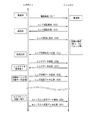
まず、撮像準備のためのカメラシステム1の動作を説明する。図2は、カメラシステム1の撮像準備動作を説明するための信号送受信の遷移を示す図である。
[2. Camera system operation)
[2-1. (Image preparation operation)
First, the operation of the
カメラボディ100に交換レンズ200を装着した状態で、使用者が、カメラボディ100の電源をONすると、電源160は、ボディマウント150及びレンズマウント250を介して、交換レンズ200に電力を供給する(S11)。
When the user turns on the power supply of the
次に、カメラコントローラー140は、レンズコントローラー240に対して、交換レンズ200の認証情報を要求する(S12)。ここで、交換レンズ200の認証情報には、交換レンズ200が装着されているか否かに関する情報及びアクセサリーが装着されているか否かに関する情報が含まれる。レンズコントローラー240は、カメラコントローラー140からのレンズ認証要求に応答する(S13)。
Next, the
次に、カメラコントローラー140は、レンズコントローラー240に対して、初期化動作をするよう要求する(S14)。
Next, the
レンズコントローラー240は、カメラコントローラー140からの初期化要求を受けて、絞りのリセット、OISレンズ220のリセット等の初期化動作を行う。そして、レンズコントローラー240は、カメラコントローラー140に対して、レンズ初期化動作が完了した旨を返信する(S15)。
In response to the initialization request from the
次に、カメラコントローラー140は、レンズコントローラー240に対して、レンズデータを要求する(S16)。
Next, the
レンズデータは、フラッシュメモリ242に格納されている。そこで、レンズコントローラー240は、フラッシュメモリ242からレンズデータを読み出して、カメラコントローラー140に返信する(S17)。ここで、「レンズデータ」とは、レンズ名称、Fナンバー、焦点距離等の交換レンズ200特有の特性値である。
The lens data is stored in the
カメラコントローラー140が、カメラボディ100に装着されている交換レンズ200のレンズデータを把握すると、撮像可能な状態になる。この状態では、カメラコントローラー140は、レンズコントローラー240に対して、交換レンズ200の状態を示すレンズ状態データを定期的に要求する(S18)。レンズ状態データは、例えば、ズームレンズ210によるズーム倍率情報、フォーカスレンズ230の位置情報、絞り値情報などが含まれる。
When the
レンズコントローラー240は、カメラコントローラー140からのレンズ状態データ要求を受けて、カメラコントローラー140に対して、要求されたレンズ状態データを返信する(S19)。
In response to the lens state data request from the
また、この状態では、カメラシステム1は、CCDイメージセンサー110で生成した画像データが示す画像(スルー画像)を液晶モニタ120に表示する制御モードで動作し得る。この制御モードを「ライブビューモード」という。ライブビューモードでは、CCDイメージセンサー110で撮像されている画像(スルー画像)が液晶モニタ120に表示されるので、使用者は、液晶モニタ120に表示されているスルー画像を見ながら静止画像を撮像するための構図を決めることができる。カメラシステム1をライブビューモードに設定するかどうかは、使用者が選択可能である。ライブビューモードの他に、使用者が選択できる制御モードとしては、交換レンズ200からの被写体像を光学ビューファインダー(図示省略)に導く制御モードもある。この制御モードを実現するためには、被写体像を光学ビューファインダー(図示省略)に導くための可動ミラー等が必要である。ライブビューモードにおけるオートフォーカス動作の方式としては、コントラスト方式が適している。ライブビューモードでは、定常的に、CCDイメージセンサー110で画像データを生成しているので、その画像データを用いたコントラスト方式のオートフォーカス動作をするのが容易だからである。
In this state, the
コントラスト方式のオートフォーカス動作を行う際には、カメラコントローラー140は、レンズコントローラー240に対して、コントラストAF用データを要求する(S20)。コントラストAF用データは、コントラスト方式のオートフォーカス動作の際に必要なデータであり、例えば、フォーカス駆動速度、フォーカスシフト量、像倍率、コントラストAF可否情報などが含まれる。
When performing the contrast autofocus operation, the
〔2−2.コントラスト方式のオートフォーカス動作〕
以上により、撮像準備が完了したカメラシステム1におけるオートフォーカス動作について、図3及び図4を参照して説明する。ここでは、コントラスト方式のオートフォーカス動作について説明する。
[2-2. (Contrast autofocus operation)
The autofocus operation in the
図3は、オートフォーカス動作を説明するためのフローチャートである。図4は、オートフォーカス動作の際のタイミングチャートである。 FIG. 3 is a flowchart for explaining the autofocus operation. FIG. 4 is a timing chart for the autofocus operation.
カメラコントローラー140は、ライブビューモードで動作しているとする。この状態で、カメラコントローラー140は、図4(a)に示すように、垂直同期信号を定期的に生成する。また、カメラコントローラー140は、これと並行して、垂直同期信号に基づいて、図4(c)に示すように、露光同期信号を生成する。これは、カメラコントローラー140が垂直同期信号を基準にして、露光開始タイミングと露光終了タイミングとを予め把握しているために、露光同期信号を生成できるのである。カメラコントローラー140は、垂直同期信号をタイミング発生器112に出力し、露光同期信号をレンズコントローラー240に出力する。レンズコントローラー240は、露光同期信号に同期して、フォーカスレンズ230の位置情報を取得する。この点については、後述する。
Assume that the
タイミング発生器112は、垂直同期信号に基づいて、CCDイメージセンサー110の読み出し信号と図4(b)に示すように電子シャッター駆動信号とを定期的に生成する。タイミング発生器112は、読み出し信号及び電子シャッター駆動信号に基づいて、CCDイメージセンサー110を駆動する。
The
すなわち、CCDイメージセンサー110は、読み出し信号に応じて、CCDイメージセンサー110内に多数存在する光電変換素子(図示省略)で生成された画素データを垂直転送部(図示省略)に読み出す。本実施の形態1では、読み出し信号と垂直同期信号とは一致しているが、本発明を実施する上で、このことは必須事項ではない。つまり、垂直同期信号と読み出し信号とがずれていてもよい。要するに、垂直同期信号と読み出し信号との同期がとれていればよい。
That is, the
また、CCDイメージセンサー110は、電子シャッター駆動信号に応じて、電子シャッター動作を行う。これにより、CCDイメージセンサー110は、不要電荷を外部に掃き出すことができる。電子シャッター駆動信号は、短時間の間に定期的に発信される複数の信号の群からなる。例えば、10個の信号を一群として発信する。CCDイメージセンサー110は、一群の電子シャッター駆動信号が発信されている間、一つの信号に対して、一回の電子シャッター動作を行う。一群の電子シャッター駆動信号に含まれる信号数を増やせば、CCDイメージセンサー110内に蓄積した電荷を確実に掃き出すことができる。しかし、CCDイメージセンサー110の駆動方法が煩雑になる。
Further, the
従って、CCDイメージセンサー110は、電子シャッター駆動信号により電荷を掃き出し、読み出し信号により画素データを垂直転送部(図示省略)に読み出すので、一群の電子シャッター駆動信号の最後の信号から垂直同期信号までの期間、スルー画像用の画像データのために露光動作を行うことになる(図4(c)参照)。
Therefore, the
以上の状態で、カメラコントローラー140は、レリーズ釦130が半押し操作されるかどうかを監視する(S31)。今、図4において、タイミングt1にレリーズ釦130が半押し操作されたとする。すると、カメラコントローラー140は、図4(d)に示すように、レンズコントローラー240に対して、AF開始コマンドを発信する。AF開始コマンドは、コントラスト方式のオートフォーカス動作を開始する旨を示すコマンドである。
In the above state, the
レンズコントローラー240は、AF開始コマンドを受けて、フォーカスモータ233の制御モードを第1制御モードから第2制御モードに変更する(S32)。第1制御モードは、レンズコントローラー240が意図しないフォーカスレンズ230の駆動方向の反転について相対的に検出精度が劣る制御モードであり、第2制御モードは、レンズコントローラー240が意図しないフォーカスレンズ230の駆動方向の反転について相対的に検出精度が優れる制御モードである。より具体的には、第1制御モードは、第1エンコーダ231の検出結果のみに基づいて、フォーカスモータ233を制御する制御モードであり、第2制御モードは、第1エンコーダ231及び第2エンコーダ232の検出結果に基づいて、フォーカスモータ233を制御する制御モードである。
In response to the AF start command, the
また、レンズコントローラー240は、第2制御モードに変更したときのカウンタ243の数値(パルス数)をDRAM241に記憶しておく。そして、レンズコントローラー240は、この値を基準にして、フォーカスモータ233を制御する。
Further, the
このように、コントラスト方式のオートフォーカス動作中において、フォーカスモータ233の制御モードを第2制御モードとするのは、コントラスト方式のオートフォーカス動作の場合、合焦点を算出する途中でフォーカスモータ233が反転してしまう場合があり、そのような反転を正確に把握する必要があるからである。フォーカスレンズ230の駆動の反転は、フォーカスモータ233に印加している駆動電力の正負を判別することにより、ある程度は把握することができる。しかし、フォーカスレンズ230を駆動しているときには、フォーカスモータ233に印加する駆動電力の正負状態は変わらないのに、フォーカスレンズ230の駆動方向が反転してしまう場合がある。このような場合に第1制御モードで制御していたのでは、レンズコントローラー240は、フォーカスレンズ230の駆動方向が反転したことを把握できない。そのため、フォーカスレンズ230の駆動方向の反転について相対的に検出精度が劣ることになる。これに対して、第2制御モードで制御すれば、レンズコントローラー240は、逆転中のパルス数の変化を減算することにより、現在のパルス数を正確に算出できる。つまり、フォーカスレンズ230の駆動方向の反転について、相対的に検出精度が優れることになる。この精度の優劣は、フォーカスレンズ230の移動方向の反転のうち、レンズコントローラー240が意図しない反転について、レンズコントローラー240が把握できるかどうかによって、決定される。
As described above, the control mode of the
次に、コントラスト方式のオートフォーカス動作を開始する前に第1制御モードで制御しておく理由を説明する。端的に説明すれば、このようなコントラスト方式のオートフォーカス動作を開始する前の状態では、レンズコントローラー240は、意図しないフォーカスモータ233の反転を把握する必要がないからである。必要がない場合に、第2制御モードで制御すると、単にシステムを複雑化してしまうだけなので、このような場合には第1制御モードで制御するのである。コントラスト方式のオートフォーカス動作をしない場合には、ある位置から一方向についてあるパルス数を移動させれば十分なのである。言い換えれば、コントラスト方式のオートフォーカス動作では、フォーカスモータ233の反転を考慮した絶対的な位置制御が必要なのに対し、それ以外の動作では、フォーカスモータ233の反転を考慮しない相対的な位置制御で十分なのである。
Next, the reason for controlling in the first control mode before starting the contrast-type autofocus operation will be described. In short, it is because the
また、絶対的な位置制御を続けていると、カウンタ243でカウントされているパルス数と実際の位置とが乖離してくる場合がある。これは、反転の際のフォーカスモータ233等のバックラッシュに基づく誤差が蓄積するからである。これに対して、コントラスト方式のオートフォーカス動作開始の前後で、制御モードを第1制御モードから第2制御モードに変更するようにすると、コントラスト方式のオートフォーカス動作中のフォーカスレンズ230の位置制御を正確に行うことができる。制御モードを第1制御モードから第2制御モードに変更するようにすると、その変更の際に、基準となるパルス数を記憶する必要があり、コントラスト方式のオートフォーカス動作においてその動作開始直前のパルス数を基準にしてフォーカスレンズ230の位置制御を行うからである。コントラスト方式のオートフォーカス動作開始直前のパルス数を基準にすることで、絶対的な位置制御の基準パルス値とフォーカスレンズ230の実際の位置との乖離を小さくできるのである。基準パルス値を把握した時点からのコントラスト方式のオートフォーカス動作までの時間を短くでき、その時間が短いということは、フォーカスモータ233の反転回数も少ないということが言えるからである。
If absolute position control is continued, the number of pulses counted by the
その後、カメラコントローラー140は、タイミングt2に、レンズコントローラー240に対して、開始点移動コマンドを送信する。このコマンドは、コントラスト方式のオートフォーカス動作を開始する際に、フォーカスレンズ230をどの位置に移動し、AF評価値を検出中にどの方向にフォーカスレンズ230を移動させるかを示すコマンドである。レンズコントローラー240は、これを受けて、フォーカスモータ233を制御する。フォーカスモータ233は、レンズコントローラー240の制御により、開始点移動コマンドが示す位置にフォーカスレンズ230を移動させる(S33)。
Thereafter, the
次に、カメラコントローラー140は、タイミングt3に、レンズコントローラー240に対して、移動開始コマンドを発信する(S34)。レンズコントローラー240は、フォーカスレンズ230の位置情報の周期的な送信を開始する。
Next, the
この期間では、図4(h)に示すように、レンズコントローラー240は、フォーカスモータ233をカメラコントローラー140からの指示に応じて駆動すると共に、露光同期信号がOFFからONに切り替わったときのカウンタ243のパルス数と、露光同期信号がONからOFFに切り替わったときのカウンタ243のパルス数とを、順次DRAM241に保存する(S35)。
In this period, as shown in FIG. 4 (h), the
次に、カメラコントローラー140は、レンズコントローラー240に対して、周期的に、レンズ位置情報取得コマンドを送信する。これを受けて、レンズコントローラー240は、DRAM241に保存されたパルス数を露光同期信号と関連付けた状態でカメラコントローラー140に送信する(S36)。
Next, the
一方、CCDイメージセンサー110は、露光期間中に露光され、生成された画像データをADコンバーター111を介してカメラコントローラー140に送信する(S37)。
On the other hand, the
カメラコントローラー140は、受信した画像データに基づいて、オートフォーカス動作用の評価値(以下、便宜上、AF評価値という)を算出する。具体的には、CCDイメージセンサー110で生成された画像データから輝度信号を求め、輝度信号の画面内における高周波成分を積算して、AF評価値を求める方法が知られている。この算出したAF評価値は、露光同期信号と関連付けた状態でDRAM141に保存される。そして、レンズコントローラー240から取得したレンズ位置情報も露光同期信号と関連付けられている。そのため、カメラコントローラー140は、AF評価値をレンズ位置情報と関連付けて保存することができる(S38)。例えば、図4(c)中の期間bにおいて露光された画像データを用いて算出されたAF評価値は、タイミングt4におけるフォーカスレンズ230の位置とタイミングt5におけるフォーカスレンズ230の位置との平均値と関連付けられて保存される。そのようにして、図4(c)中の期間bにおいて露光された画像データを用いて算出されたAF評価値は、タイミングt6にDRAM141に保存される。
The
次に、カメラコントローラー140は、DRAM141に保存されたAF評価値に基づいて、合焦点を抽出できたかどうかを監視する(S39)。具体的には、AF評価値が極大値となるフォーカスレンズ230の位置を合焦点として抽出する。合焦点を抽出できなかった場合には、ステップS35に戻る。そして、合焦点を抽出できるまで、ステップS35〜ステップS39までの動作を繰り返す。
Next, the
ステップS39において、合焦点を抽出できると、カメラコントローラー140は、レンズコントローラー240に対して、合焦位置移動コマンドを送信する。合焦位置移動コマンドは、どの方向からどの位置にフォーカスレンズ230を移動させるかを示すコマンドである。レンズコントローラー240は、この合焦位置移動コマンドに従って、フォーカスモータ233を駆動する。カメラコントローラー140は、合焦点への移動が完了すると、レンズコントローラー240に対して、AF完了コマンドを送信する(タイミングt8、S40)。レンズコントローラー240は、これを受けて、図4(e)に示すように、フォーカスモータ233の制御方法を、第2制御モードから第1制御モードに戻す。以上により、コントラスト方式でオートフォーカス動作を完了し、ライブビューモードでの制御に戻る(S40)。
In step S39, when the in-focus point can be extracted, the
〔3.実施の形態の効果、他〕
以上のように、本発明の実施の形態1に係るカメラシステム1は、交換レンズ200とカメラボディ100とを含む。カメラボディ100は、定期的にタイミング信号を生成するカメラコントローラー140と、生成されたタイミング信号と相関のあるタイミングで露光して、画像データを生成するCCDイメージセンサー110と備える。また、カメラコントローラー140は、生成された画像データに基づいて、オートフォーカス用の評価値を算出する。また、カメラコントローラー140は、カメラボディ100を制御する。交換レンズ200は、光軸方向に進退することにより、被写体像のフォーカス状態を変化させるフォーカスレンズ230と、フォーカスレンズ230を駆動するためのフォーカスモータ233と、フォーカスレンズ230又はフォーカスレンズ230に連動する機構部材の位置を検出する第1エンコーダ231、第2エンコーダ232及びカウンタ243からなる構成と、カメラコントローラー140からの制御信号に応じて、フォーカスモータ233を制御するレンズコントローラー240と、を備える。レンズコントローラー240は、カメラコントローラー140とタイミング発生器112とからなる構成で生成されたタイミング信号をカメラボディ100から取得し、タイミング信号の取得に応じて第1エンコーダ231、第2エンコーダ232及びカウンタ243からなる構成にフォーカスレンズ230の位置を検出させ、その検出されたフォーカスレンズ230の位置をカメラボディ100に通知する。カメラコントローラー140は、カメラコントローラー140とタイミング発生器112とからなる構成で生成されたタイミング信号に基づいて、レンズコントローラー240から取得したフォーカスレンズ230又は機構部材の位置とカメラコントローラー140で算出された評価値とを関連付け、該関連付けられた位置及び評価値に基づいて、カメラシステム1のオートフォーカス動作を制御する。
[3. Effects of the embodiment, etc.]
As described above, the
これにより、カメラコントローラー140がレンズコントローラー240に対して露光同期信号を送信し、レンズコントローラー240は露光同期信号に同期してフォーカスレンズ230の位置情報を取得するので、カメラコントローラー140は、フォーカスレンズ230の位置情報の取得タイミングを正確に把握できる。また、カメラコントローラー140は、露光同期信号に同期したAF評価値を算出できる。そのため、レンズコントローラー240から取得したフォーカスレンズ230の位置情報と算出したAF評価値とを正確に対応付けることができる。そのため、コントラスト方式のオートフォーカス動作において、合焦点を正確に求めることができる。以上より、フォーカス状態の良好なカメラシステム1を得ることができる。
Accordingly, the
ここで、本実施の形態1では、本発明のタイミング信号として、CCDイメージセンサー110の露光同期信号を用いた。露光同期信号は、CCDイメージセンサー110における露光の開始を示す信号とCCDイメージセンサー110における露光の終了を示す信号とからなる信号である。すなわち、露光同期信号の立ち上がりは、CCDイメージセンサー110における露光の開始を示し、露光同期信号の立ち下がりは、CCDイメージセンサー110における露光の終了を示す。
Here, in the first embodiment, the exposure synchronization signal of the
また、本実施の形態1のカメラシステムにおいて、レンズコントローラー240は、第1エンコーダ231、第2エンコーダ232及びレンズコントローラー240からなる構成で検出されたフォーカスレンズ230の位置に基づいて、第1制御モード又は第2制御モードでフォーカスモータ233を制御するとした。ここで、第1制御モードは、第1エンコーダ231及びカウンタ243からなる構成の検出結果のみでは、フォーカスレンズ230の駆動方向の反転をレンズコントローラー240が検出できない制御モードである。第2制御モードは、第1エンコーダ231、第2エンコーダ232及びカウンタ243からなる構成の検出結果のみに基づいて、フォーカスレンズ230の駆動方向の反転をレンズコントローラー240が検出できる制御モードである。そして、レンズコントローラー240は、カメラボディ100から送られるオートフォーカス動作を開始する命令を含む信号に応じて、制御モードを第1制御モードから第2制御モードに切り替える。
Further, in the camera system of the first embodiment, the
これにより、コントラスト方式のオートフォーカス中においては、フォーカスレンズ230の駆動方向の反転をより正確に判別することにより、合焦点をより正確に抽出することができる。一方、その他の動作時は、より容易なフォーカスレンズ230の位置検出方式を採用することにより、カメラシステム1の制御を容易にすることができる。
Thereby, during the contrast type autofocus, the in-focus point can be extracted more accurately by more accurately determining the inversion of the driving direction of the
より詳細には、本実施の形態1では、交換レンズ200は、フォーカスモータ233の駆動量を検出するための第1エンコーダ231及び第2エンコーダ232を、さらに備える。レンズコントローラー240は、第1制御モードでは、第1エンコーダ231からの信号に基づいて、フォーカスモータ233を制御する一方、第2制御モードでは、第1エンコーダ231及び第2エンコーダ232からの信号に基づいて、フォーカスモータ233を制御可能な構成とした。
More specifically, in the first embodiment, the
(実施の形態2)
上述したように、本実施の形態1では、カメラコントローラー140で生成されるタイミング信号として、CCDイメージセンサー110の露光同期信号を用いた。これに対して、本実施の形態2では、カメラコントローラー140で生成されるタイミング信号として、CCDイメージセンサー110の垂直同期信号を用いる。なお、本発明の実施の形態2に係るカメラシステムは、実施の形態1に係るカメラシステム1と同様の構成であるため、図1に示すブロック図を参照して説明する。
(Embodiment 2)
As described above, in the first embodiment, the exposure synchronization signal of the
図5は、実施の形態2に係るカメラシステム1のコントラスト方式のオートフォーカス動作におけるタイミングチャートである。
FIG. 5 is a timing chart in the contrast-type autofocus operation of the
カメラコントローラー140は、図5(a)に示すように、タイミング発生器112に対して垂直同期信号を送信するとともに、レンズコントローラー240に対しても垂直同期信号を送信する。
As shown in FIG. 5A, the
CCDイメージセンサー110は、図5(b)に示すように、実施の形態1と同様に、タイミング発生器112の制御に基づいて、AF評価値算出用の画像データを垂直同期信号に同期して生成する。
As shown in FIG. 5B, the
一方、レンズコントローラー240は、図5(g)に示すように、垂直同期信号を受けたタイミングでフォーカスレンズ230の位置情報を取得する。つまり、垂直同期信号を受けたタイミングでカウンタ243のパルス数を取得する。
On the other hand, as shown in FIG. 5G, the
これにより、カメラコントローラー140は、AF評価値とフォーカスレンズ230の位置情報とを関連付けて保存する。例えば、図5(b)に示すように、期間bに露光された画像データ(タイミングt14の垂直同期信号に同期して生成された画像データ)に基づいて算出されたAF評価値と、タイミングt14の垂直同期信号に同期して取得されたフォーカスレンズ230の位置情報とを、互いに関連付けた状態で、DRAM141に記憶する(図5(j)における期間b参照)。
Thereby, the
このようにして、AF評価値をフォーカスレンズ230の位置情報と関連付けて順次保存することができる。その他の点は、実施の形態1に示すのと同様である。
In this way, the AF evaluation value can be sequentially stored in association with the position information of the
なお、本実施の形態2では、AF評価値を、垂直同期信号に同期して取得したフォーカスレンズ230の位置情報と関連付けることとしたが、これには限らない。例えば、垂直同期信号に同期して取得したフォーカスレンズ230の位置情報を補間処理することにより、CCDイメージセンサー110の露光期間におけるフォーカスレンズ230の平均位置を求め、この平均位置をAF評価値と関連付けるようにしてもよい。
In the second embodiment, the AF evaluation value is associated with the position information of the
(実施の形態3)
本発明の実施の形態1では、撮像素子は、CCDイメージセンサー110で構成したが、MOSイメージセンサーで構成してもよい(MOS:metal oxide semiconductor)。MOSイメージセンサーは、CCDイメージセンサーと異なって、一画面内において、露光タイミングが異なるので、その点を考慮して、AF評価値とフォーカスレンズ230の位置情報とを対応付ける必要がある。そのため、MOSイメージセンサーを搭載する場合には、一画面内の露光タイミングの遅延時間(以下、便宜上、露光遅延時間という)を把握し、露光遅延時間にも同期してフォーカスレンズ230の位置情報を取得するのが望ましい。
(Embodiment 3)
In the first embodiment of the present invention, the image sensor is configured by the
なお、MOSイメージセンサーを備えたカメラシステムは、図1において、CCDイメージセンサー110に代え、MOSイメージセンサーを備えた構成に等しい。そのため、MOSイメージセンサーを備えたカメラシステム(以下、カメラシステム3という)の構成の詳細な説明は省略する。
The camera system provided with the MOS image sensor is equivalent to a configuration provided with a MOS image sensor in place of the
図6は、カメラシステム3の露光タイミングを示すタイミングチャートである。カメラシステム3においても、カメラコントローラー140は、垂直同期信号を生成する。また、カメラコントローラー140は、露光同期信号を生成する。図6(b)に示すように、露光同期信号は、図6(a)に示す垂直同期信号と同期する。
FIG. 6 is a timing chart showing the exposure timing of the camera system 3. Also in the camera system 3, the
露光同期信号が立ち上がると、図6(c)に示すように、MOSイメージセンサーの第1ラインの露光が開始される(タイミングt21)。次に、少し遅延したタイミングに第2ラインの露光が開始される。このようにして、各ラインごとに露光開始タイミングが少しずつずれて、最終ラインは、タイミングt22に露光が開始される。その後、タイミングt23に第1ラインの露光が完了し、タイミングt24に最終ラインの露光が完了する。 When the exposure synchronization signal rises, as shown in FIG. 6C, exposure of the first line of the MOS image sensor is started (timing t21). Next, exposure of the second line is started at a slightly delayed timing. In this way, the exposure start timing is slightly shifted for each line, and exposure of the final line is started at timing t22. Thereafter, the exposure of the first line is completed at timing t23, and the exposure of the final line is completed at timing t24.
ここで、タイミングt21とタイミングt22との間の遅延時間又はタイミングt23とタイミングt24との間の遅延時間を露光遅延時間という。この露光遅延時間は、各MOSイメージセンサー特有の値であり、カメラボディ100の製造時にメーカーが予め入力することにより、カメラコントローラー140が把握できる値である。露光遅延時間は、露光時間の長短に影響を受けることのないほぼ一定の値である。
Here, the delay time between the timing t21 and the timing t22 or the delay time between the timing t23 and the timing t24 is referred to as an exposure delay time. This exposure delay time is a value peculiar to each MOS image sensor, and is a value that can be grasped by the
したがって、カメラコントローラー140は、露光同期信号に基づいて、最終ラインの露光終了タイミングを算出できる。そこで、カメラコントローラー140は、露光同期信号の立ち上がり時、立ち下がり時、及び最終ラインの露光終了時に、それぞれ対応する位置検出同期信号を生成する(図6(d)参照)。
Therefore, the
カメラコントローラー140は、レンズコントローラー240に対して位置検出同期信号を送信する。これを受信したレンズコントローラー240は、位置検出同期信号に同期して、カウンタ243のパルス値を読み出す。そして、読み出したパルス値をカメラコントローラー140に送信する。
The
以上により、カメラコントローラー140は、最終ラインの露光完了時のフォーカスレンズ230の位置情報も得ることができるので、AF評価値とフォーカスレンズの位置との対応付けをより正確に行うことができる。
As described above, the
なお、本実施の形態3では、最終ラインの露光完了時のフォーカスレンズ230の位置情報を取得するとしたが、これには限らない。例えば、最終ラインの露光開始時のフォーカスレンズ230の位置情報を取得するようにしてもよい。要するに、MOSイメージセンサーを用いることにより生じる露光遅延時間に関係するタイミングで、フォーカスレンズ230の位置情報を取得するようにすればよい。
In the third embodiment, the position information of the
また、本実施の形態3では、カメラコントローラー140が露光遅延時間に関係するタイミングで位置検出同期信号を生成し、この位置検出同期信号をレンズコントローラー240に送信する構成としたが、この構成には限らない。例えば、カメラコントローラー140が露光遅延時間を予めレンズコントローラー240に送信しておく構成にしてもよい。この場合、図2に示す撮像準備動作において、カメラコントローラー140からレンズコントローラー240に露光遅延時間を通知するようにすればよい。また、この場合、カメラコントローラー140は、レンズコントローラー240に対して、露光同期信号を送信し、レンズコントローラー240が受信した露光同期信号と通知された露光遅延時間とに基づいて、位置検出同期信号に相当する信号を生成して、この信号に同期してフォーカスレンズ230の位置情報を取得するようにすればよい。
In the third embodiment, the
(実施の形態4)
本発明の実施の形態1〜3においては、主に静止画撮像の際のコントラスト方式のオートフォーカス動作について説明した。本実施の形態4では、動画撮像の際のコントラスト方式のオートフォーカス動作について説明する。なお、本実施の形態4では、「動画撮像」は、スルー画像用の動画撮像と、メモリーカード171への記録用の動画撮像とを含む。
(Embodiment 4)
In the first to third embodiments of the present invention, the contrast type autofocus operation at the time of still image capturing has been mainly described. In the fourth embodiment, a contrast-type autofocus operation when capturing a moving image will be described. In the fourth embodiment, “moving image capturing” includes moving image capturing for through images and moving image recording for recording on the
本実施の形態4のカメラシステムの構成は、図1に示す本発明の実施の形態1のカメラシステム1の構成と同様であるため、説明を省略する。
The configuration of the camera system according to the fourth embodiment is the same as that of the
カメラコントローラー140は、レンズコントローラー240に対して、露光同期信号を送信する。この送信動作は、静止画撮像の際だけでなく、動画撮像の際にも行われる。そして、レンズコントローラー240は、露光同期信号に同期してウォブリング制御を行う。ここで、「ウォブリング制御」とは、レンズコントローラー240が行う制御である。ウォブリング制御モードにおいて、レンズコントローラー240は、フォーカスレンズ230を微小距離だけ周期的に進退させるようフォーカスモータ233を制御する。これにより、カメラコントローラー140は、動画撮像中に、被写体のカメラに対する相対位置が変動した場合に、被写体にフォーカスを合わせるためのフォーカスレンズ230の移動方向を、迅速に把握できる。
The
本発明は、ウォブリング制御を露光同期信号に同期させることを主眼とするものである。これにより、CCDイメージセンサー110による動画撮像とフォーカスレンズ230のウォブリング制御とを簡単に同期させることができる。これにより、簡単な方法でウォブリングの影響を最小限に抑えることができるため、良好な動画を撮像できる。また、カメラコントローラー140からレンズコントローラー240に対して送信されるウォブリングに必要な情報の種類を少なくできるので、カメラシステム1の制御を簡単にできる。
The main object of the present invention is to synchronize wobbling control with an exposure synchronization signal. Thereby, the moving image imaging by the
図7を参照して、本実施の形態4のウォブリング動作を詳細に説明する。図7は、ウォブリング動作中のタイミングチャートである。 With reference to FIG. 7, the wobbling operation of the fourth embodiment will be described in detail. FIG. 7 is a timing chart during the wobbling operation.
カメラコントローラー140は、図7(a)に示すように、レンズコントローラー240に対して、露光同期信号を送信する。また、カメラコントローラー140は、ウォブリング動作を始める際に、ウォブリング動作を開始する旨を示すウォブリング開始コマンドをレンズコントローラー240に対して送信する。ここでは、タイミングt31に、カメラコントローラー140がウォブリング開始コマンドを送信したとする。このウォブリング開始コマンドは、ウォブリングの振幅と移動量を含むコマンドである。「振幅」とは、フォーカスレンズ230の微小振動の振幅である。「移動量」とは、微小振動の一周期における初めと終わりとの振幅差である。移動量が0でなく、正又は負の値を有する場合、フォーカスレンズ230は、ウォブリングしながら一方方向に移動していることを示す。これに対して、移動量が0の場合、フォーカスレンズ230は、一定位置においてウォブリングしていることを示す。
The
レンズコントローラー240は、ウォブリング開始コマンドを受信すると、露光同期信号の次の立ち下がりのタイミングに同期して、ウォブリング制御を開始する(タイミングt32)。ウォブリング制御において、レンズコントローラー240は、露光同期信号がHighのときは、フォーカスレンズ230を一定位置に保持するようフォーカスモータ233を制御する一方、露光同期信号がLowのときは、フォーカスレンズ230を移動するようフォーカスモータ233を制御する。露光同期信号がHighのとき、CCDイメージセンサー110は、動画の1フレームを撮像するのであるが、この期間はフォーカスレンズ230を動かさないようにして、動画撮像に対するウォブリング動作の影響が最小限になるようにしているのである。従って、図7(d)に示すように、タイミングt32〜t33及びタイミングt34〜t35の間(この期間を停止期間という)はフォーカスレンズ230を移動し、タイミングt33〜t34及びタイミングt35〜t37の間(この期間を露光期間という)はフォーカスレンズ230の位置を一定位置に保つ。なお、図7(a)及び図7(d)に示す通り、露光同期信号の2周期分で、ウォブリング動作の1周期分に相当する。
Upon receiving the wobbling start command, the
レンズコントローラー240は、ウォブリング開始コマンドに含まれる振幅及び移動量に従って、フォーカスレンズ230を、タイミングt32〜t33の期間は振幅分だけ負方向に移動させ、タイミングt33〜t34の期間は一定位置に保持させ、タイミングt34〜t35の期間は振幅と移動量を加算した分だけ正方向に移動させ、タイミングt35〜t37の期間は一定位置に保持させる。
The
次に、タイミングt36に、カメラコントローラー140が新たなウォブリング開始コマンドを送信したとする。すると、レンズコントローラー240は、新たなウォブリング開始コマンドに含まれる振幅及び移動量に従って、ウォブリング制御を更新する(タイミングt37)。
Next, it is assumed that the
そして、最後に、カメラコントローラー140は、ウォブリング動作を終了させる際に、レンズコントローラー240に対して、ウォブリング終了コマンドを送信する(タイミングt38)。これを受けて、レンズコントローラー240は、ウォブリング制御を終了する(タイミングt39)。
Finally, when ending the wobbling operation, the
以上のように、本発明の実施の形態4にかかるカメラシステム1は、交換レンズ200とカメラボディ100とを含むカメラシステムである。カメラボディ100は、定期的に露光同期信号を生成するカメラコントローラー140と、生成された露光同期信号と相関のあるタイミングで露光して、画像データを生成するCCDイメージセンサー110と、生成された画像データに基づいて、オートフォーカス用の評価値を算出し、また、カメラボディ100を制御するカメラコントローラー140と、を備える。交換レンズ200は、光軸方向に進退することにより、被写体像のフォーカス状態を変化させるフォーカスレンズ230と、フォーカスレンズ230を駆動するためのフォーカスモータ233と、カメラコントローラー140からの制御信号に応じて、フォーカスモータ233を制御するレンズコントローラー240と、を備える。そして、レンズコントローラー240は、カメラコントローラー140で生成された露光同期信号をカメラボディ100から取得し、取得した露光同期信号に同期してフォーカスレンズ230を微小距離だけ周期的に進退させるようフォーカスモータ233を制御する。
As described above, the
これにより、簡単な構成で、CCDイメージセンサー110による動画撮像とフォーカスレンズ230のウォブリング制御とを簡単に同期させることができる。これにより、簡単な方法でウォブリングの影響を抑えることができるため、良好な動画を撮像できる。
Thereby, it is possible to easily synchronize the moving image capturing by the
また、仮に、カメラコントローラー140からレンズコントローラー240に対して露光同期信号を送信しない場合には、次のような動作が考えられる。第1に、カメラコントローラー140が、露光同期信号に同期させた状態で、ウォブリングに関する制御信号を、レンズコントローラー240に対して送信する動作が考えられる。第2に、レンズコントローラー240が露光同期信号と一致する信号を自ら生成して、その信号に同期してウォブリング制御を行う。これらは、いずれにしても、カメラボディ100と交換レンズ200との通信を煩雑にし、又は、露光タイミングとウォブリング制御との同期が取れ難いものとなる。従って、本発明のように、カメラコントローラー140がレンズコントローラー240に対して露光同期信号を送信し、レンズコントローラー240が露光同期信号に同期してウォブリング制御するよう構成することにより、カメラボディ100と交換レンズ200との通信を簡素化でき、又は、露光タイミングとウォブリング制御との同期を取り易くできるのである。そのため、簡単な方法で、ウォブリングの影響を抑えた良好な動画を撮像できるのである。
Further, if an exposure synchronization signal is not transmitted from the
(その他の実施の形態)
以上により、本発明の実施の形態として、実施の形態1〜4を説明した。しかし、本発明は、これらには限定されない。そこで、本発明の他の実施の形態を本欄にまとめて説明する。
(Other embodiments)
As described above,
本発明の実施の形態1では、第1エンコーダ231及び第2エンコーダ232を用いる第2制御モードを例示した。しかし、本発明の第2制御モードはこれには限定されない。例えば、1つのエンコーダと線状の位置検出センサーとを用いた場合でも第2制御モードを実現できる。線状の位置検出センサーとは、例えば、フォーカスレンズ230の駆動範囲と同じ長さの線状の抵抗体と、その抵抗体の上を接触しつつ、フォーカスレンズ230の駆動と連動して移動する接触子とによって実現できる位置センサーである。要するに、第2制御モードは、第1制御モードに比べて、レンズコントローラー240が意図しないフォーカスレンズ230の駆動方向の反転について相対的に位置検出精度が優れる制御モードであればよい。
In the first embodiment of the present invention, the second control mode using the
本発明の実施の形態1〜3では、ズームレンズ210及びOISレンズ220を有する構成を例示したが、これらは、本発明に必須の構成ではない。すなわち、ズーム機能を有することのない単焦点レンズを装着したカメラシステムにも本発明は適用可能であるし、手振れ補正機能を有することのない交換レンズを装着したカメラシステムにも本発明は適用可能である。
In the first to third embodiments of the present invention, the configuration including the
本発明の実施の形態1〜3では、可動ミラーを備えないカメラボディを例示したが、本発明はこれには限定されない。例えば、カメラボディ内に可動ミラーを備えてもよいし、被写体像を分けるためのプリズムを備えてもよい。また、カメラボディ内ではなく、アダプター内に可動ミラーを備える構成でもよい。
In
本発明の実施の形態1〜3では、フォーカスレンズ230の位置を直接検出せず、フォーカスモータ233の回転軸の回転角を検出することにより、間接的に検出した。このように、本発明においては、フォーカスレンズ230の位置を直接的に検出してもよいし、フォーカスレンズ230に連動する機構部材の位置を検出することによって間接的に検出してもよい。要するに、結果として、フォーカスレンズの位置を特定できればよい。
In
本発明の実施の形態1〜3では、位相差検出センサーを搭載しないカメラシステムを例示した。しかし、本発明はこのような実施例には限定されない。位相差検出センサーを搭載して、位相差方式のオートフォーカス動作とコントラスト方式のオートフォーカス動作を選択的に実行できるようにしてもよい。この場合、コントラスト方式のオートフォーカス動作を実行しているときに、本発明は適用可能である。 In the first to third embodiments of the present invention, a camera system not equipped with a phase difference detection sensor is illustrated. However, the present invention is not limited to such examples. A phase difference detection sensor may be mounted so that a phase difference type autofocus operation and a contrast type autofocus operation can be selectively executed. In this case, the present invention is applicable when a contrast type autofocus operation is being performed.
本発明の実施の形態1では、CCDイメージセンサー110の露光同期信号を、本発明のタイミング信号の一例として示した。しかし、本発明のタイミング信号は露光同期信号には限らない。例えば、CCDイメージセンサー110のための垂直同期信号と電子シャッター駆動信号とを、タイミング信号としてレンズコントローラー240に送信するようにしてもよい。これにより、カメラコントローラー140は、露光同期信号を送信する必要がないので、制御を容易にすることができる。ただし、この場合、電子シャッター駆動信号の仕様(1群内における発信間隔や発信数等)を予め、カメラコントローラー140からレンズコントローラー240に通知しておく必要がある。レンズコントローラー240は、通知された仕様に従って、電子シャッター駆動信号と垂直同期信号とに基づいて、カウンタ243のパルス値を読み出す。
In the first embodiment of the present invention, the exposure synchronization signal of the
本発明の実施の形態4では、カメラコントローラー140からレンズコントローラー240に対して露光同期信号を送信し、ウォブリング動作を露光同期信号に同期させるようにしたが、本発明はこの制御には限定されない。例えば、カメラコントローラー140からレンズコントローラー240に対して垂直同期信号を送信し、ウォブリング動作を垂直同期信号に同期させるようにしてもよい。図8は、垂直同期信号と露光期間のタイミングチャートである。図8(a)は垂直同期信号、図8(b)は周波数が垂直同期信号の2倍の時の露光期間、図8(c)は周波数が垂直同期信号と同じ時の露光期間、図8(d)は周波数が垂直同期信号の1/2倍の時の露光期間を示す。但し、この場合、垂直同期信号と露光期間とのタイミングが分かる情報を、カメラコントローラー140からレンズコントローラー240に対して送信するようにしなければならない。レンズコントローラー240は、ウォブリング動作期間中の一定位置保持期間を、垂直同期信号だけでは特定できないからである。垂直同期信号と露光期間とのタイミングが分かる情報としては、例えば、垂直同期信号に対する露光期間の周期を表す周波数や、ウォブリング動作期間中の一定位置保持期間を特定する情報が挙げられる。反対に言えば、本発明の実施の形態4では、カメラコントローラー140からレンズコントローラー240に対して露光同期信号を送信し、ウォブリング動作を露光同期信号に同期させるようにしたため、垂直同期信号に対する露光期間の周期を表す周波数やウォブリング動作期間中の一定位置保持期間を特定するための情報等を通信する必要がないので、通信を簡単化することができる。
In Embodiment 4 of the present invention, an exposure synchronization signal is transmitted from the
本発明の実施の形態4では、カメラコントローラー140からレンズコントローラー240に対して露光同期信号を送信し、ウォブリング動作を露光同期信号に同期させるようにしたが、本発明はこの制御には限定されない。例えば、カメラコントローラー140からレンズコントローラー240に対して垂直同期信号を送信し、ウォブリング動作を垂直同期信号に同期させるようにしてもよい。但し、この場合、垂直同期信号と露光期間とのタイミングが分かる情報を、カメラコントローラー140からレンズコントローラー240に対して送信するようにしなければならない。レンズコントローラー240は、ウォブリング動作期間中の一定位置保持期間は、垂直同期信号だけでは特定できないからである。垂直同期信号と露光期間とのタイミングが分かる情報としては、例えば、停止期間を特定する情報が挙げられる。反対に言えば、本発明の実施の形態4では、カメラコントローラー140からレンズコントローラー240に対して露光同期信号を送信し、ウォブリング動作を露光同期信号に同期させるようにしたため、停止期間を特定するための情報等を通信する必要がないので、通信を簡単化することができる。
In Embodiment 4 of the present invention, an exposure synchronization signal is transmitted from the
また、カメラボディ100が交換レンズ200に対して通信を開始するためのトリガ信号を、タイミング信号としてレンズコントローラー240に送信するようにしてもよい。これにより、カメラコントローラー140は、露光同期信号をレンズコントローラー240に送信する必要がないので、制御を容易にすることができる。ただし、この場合、カメラコントローラー140は、上記トリガ信号の送信からレンズコントローラー240が応答するまでの遅延時間を測定しておく必要がある。レンズコントローラー240は、トリガ信号に基づいて、カウンタ243のパルス値を読み出す。カメラコントローラー140は、レンズコントローラー240によって読み出されたパルス値に対して、フォーカスレンズ230の駆動速度と上記遅延時間を使って補正を行う。これにより、上記トリガ信号に対応するフォーカスレンズ230の位置情報を得ることが可能である。
In addition, a trigger signal for the
〔付記1〕
本発明の第1のカメラシステムは、交換レンズとカメラボディとを含むカメラシステムであって、前記カメラボディは、定期的にタイミング信号を生成する信号生成手段と、前記信号生成手段で生成されたタイミング信号と相関のあるタイミングで露光して、画像データを生成する撮像素子と、前記撮像素子で生成された画像データに基づいて、オートフォーカス用の評価値を算出する評価値算出手段と、前記カメラボディを制御するボディ制御部と、を備え、前記交換レンズは、光軸方向に進退することにより、被写体像のフォーカス状態を変化させるフォーカスレンズと、前記フォーカスレンズを駆動するための駆動手段と、前記フォーカスレンズ又は前記フォーカスレンズに連動する機構部材の位置を検出する位置検出手段と、前記ボディ制御部からの制御信号に応じて、前記駆動手段を制御するレンズ制御部と、を備え、前記レンズ制御部は、前記信号生成手段で生成されたタイミング信号を前記カメラボディから取得し、前記タイミング信号の取得に応じて前記位置検出手段に前記フォーカスレンズ又は前記機構部材の位置を検出させ、その検出された前記フォーカスレンズ又は前記機構部材の位置を前記カメラボディに通知し、前記ボディ制御部は、前記信号生成手段で生成されたタイミング信号に基づいて、前記レンズ制御部から取得した前記フォーカスレンズ又は前記機構部材の位置と前記評価値算出手段で算出された評価値とを関連付け、該関連付けられた位置及び評価値に基づいて、カメラシステムのオートフォーカス動作を制御するものである。
[Appendix 1]
A first camera system of the present invention is a camera system including an interchangeable lens and a camera body, and the camera body is generated by a signal generation unit that periodically generates a timing signal and the signal generation unit. An image sensor that generates image data by exposing at a timing correlated with a timing signal, an evaluation value calculation unit that calculates an evaluation value for autofocus based on the image data generated by the image sensor, A body control unit that controls the camera body, and the interchangeable lens moves forward and backward in the optical axis direction to change the focus state of the subject image, and a driving unit for driving the focus lens Position detecting means for detecting a position of the focus lens or a mechanism member interlocked with the focus lens; A lens control unit that controls the driving unit in accordance with a control signal from the control unit, the lens control unit acquires a timing signal generated by the signal generation unit from the camera body, and In response to the acquisition of the timing signal, the position detection unit detects the position of the focus lens or the mechanism member, notifies the detected position of the focus lens or the mechanism member to the camera body, and the body control unit Associates the position of the focus lens or the mechanism member acquired from the lens control unit with the evaluation value calculated by the evaluation value calculation unit based on the timing signal generated by the signal generation unit, The autofocus operation of the camera system is controlled based on the obtained position and evaluation value.
これにより、カメラ制御部がレンズ制御部に対してタイミング信号を送信し、レンズ制御部はタイミング信号に同期してフォーカスレンズ又は機構部材の位置を取得するので、カメラ制御部は、フォーカスレンズ又は機構部材の位置の取得タイミングを正確に把握できる。また、カメラ制御部は、タイミング信号に同期した評価値を算出できる。そのため、レンズ制御部から取得したフォーカスレンズ又は機構部材の位置と算出した評価値とを正確に対応付けることができる。そのため、コントラスト方式のオートフォーカス動作において、合焦点を正確に求めることができる。以上より、フォーカス状態の良好なカメラシステムを得ることができる。 Accordingly, the camera control unit transmits a timing signal to the lens control unit, and the lens control unit acquires the position of the focus lens or the mechanism member in synchronization with the timing signal. It is possible to accurately grasp the acquisition timing of the position of the member. Further, the camera control unit can calculate an evaluation value synchronized with the timing signal. Therefore, the position of the focus lens or mechanism member acquired from the lens control unit can be accurately associated with the calculated evaluation value. Therefore, the focal point can be accurately obtained in the contrast type autofocus operation. As described above, a camera system with a good focus state can be obtained.
〔付記2〕
本発明の第1のカメラシステムにおいて、前記信号生成手段で生成されるタイミング信号は、前記撮像素子における露光の開始タイミングを示す信号と前記撮像素子における露光の終了タイミングを示す信号とからなる構成とすることができる。
[Appendix 2]
In the first camera system of the present invention, the timing signal generated by the signal generating means is composed of a signal indicating an exposure start timing in the image sensor and a signal indicating an exposure end timing in the image sensor. can do.
これにより、交換レンズは、撮像素子の露光タイミングに同期してフォーカス位置を取得できる。また、露光開始のタイミングを通知する信号と、露光終了のタイミングを通知する信号とは、情報量が少ない制御信号であるため、制御信号の通信のためのデータ量を少なくできる。 Thereby, the interchangeable lens can acquire the focus position in synchronization with the exposure timing of the image sensor. Further, since the signal for notifying the timing for starting exposure and the signal for notifying the timing for ending exposure are control signals with a small amount of information, the amount of data for communication of control signals can be reduced.
〔付記3〕
本発明の第1のカメラシステムにおいて、前記信号生成手段で生成されるタイミング信号は、前記撮像素子の駆動のための垂直同期信号と、前記撮像素子における電子シャッターの駆動のための電子シャッター駆動信号とからなる構成とすることができる。
[Appendix 3]
In the first camera system of the present invention, the timing signal generated by the signal generating means includes a vertical synchronization signal for driving the image sensor and an electronic shutter drive signal for driving an electronic shutter in the image sensor. It can be set as the structure which consists of these.
これにより、交換レンズは、撮像素子の露光タイミングに同期してフォーカス位置を取得できる。 Thereby, the interchangeable lens can acquire the focus position in synchronization with the exposure timing of the image sensor.
〔付記4〕
本発明の第1のカメラシステムにおいて、前記信号生成手段で生成されるタイミング信号は、前記撮像素子の駆動のための垂直同期信号である構成とすることができる。
[Appendix 4]
In the first camera system of the present invention, the timing signal generated by the signal generation unit may be a vertical synchronization signal for driving the image sensor.
〔付記5〕
本発明の第2のカメラシステムは、交換レンズとカメラボディとを含むカメラシステムであって、前記カメラボディは、定期的にタイミング信号を生成する信号生成手段と、前記信号生成手段で生成されたタイミング信号と相関のあるタイミングで露光して、画像データを生成する撮像素子と、前記撮像素子で生成された画像データに基づいて、オートフォーカス用の評価値を算出する評価値算出手段と、前記交換レンズに対して通信を開始するためのトリガ信号を生成するとともに、前記カメラボディを制御するボディ制御部と、を備え、前記交換レンズは、光軸方向に進退することにより、被写体像のフォーカス状態を変化させるフォーカスレンズと、前記フォーカスレンズを駆動するための駆動手段と、前記フォーカスレンズ又は前記フォーカスレンズに連動する機構部材の位置を検出する位置検出手段と、前記ボディ制御部からの制御信号に応じて、前記駆動手段を制御するレンズ制御部と、を備え、前記レンズ制御部は、前記ボディ制御部で生成されたトリガ信号を前記カメラボディから取得し、前記トリガ信号の取得に応じて前記位置検出手段に前記フォーカスレンズ又は前記機構部材の位置を検出させ、その検出されたフォーカスレンズ又は機構部材の位置を前記カメラボディに通知し、前記ボディ制御部は、前記ボディ制御部で生成されたトリガ信号に基づいて、前記レンズ制御部から取得した前記フォーカスレンズ又は前記機構部材の位置と前記評価値算出手段で算出された評価値とを関連付け、該関連付けられた位置及び評価値に基づいて、カメラシステムのオートフォーカス動作を制御するものである。
[Appendix 5]
A second camera system of the present invention is a camera system including an interchangeable lens and a camera body, wherein the camera body is generated by a signal generation unit that periodically generates a timing signal and the signal generation unit. An image sensor that generates image data by exposing at a timing correlated with a timing signal, an evaluation value calculation unit that calculates an evaluation value for autofocus based on the image data generated by the image sensor, And a body control unit that generates a trigger signal for starting communication with the interchangeable lens and controls the camera body, and the interchangeable lens moves forward and backward in the optical axis direction to focus the subject image. A focus lens for changing the state, a driving means for driving the focus lens, and the focus lens or the A position detection unit that detects a position of a mechanism member that is interlocked with the focus lens; and a lens control unit that controls the driving unit in response to a control signal from the body control unit. A trigger signal generated by a body control unit is acquired from the camera body, and the position detection unit is made to detect the position of the focus lens or the mechanism member according to the acquisition of the trigger signal, and the detected focus lens or The position of the mechanism member is notified to the camera body, and the body control unit, based on a trigger signal generated by the body control unit, and the position of the focus lens or the mechanism member acquired from the lens control unit, Associating with the evaluation value calculated by the evaluation value calculating means, and based on the associated position and evaluation value, the camera system And it controls the over autofocus operation.
これにより、ボディ制御部は、露光同期信号をレンズ制御部に送信する必要がないので、制御を容易にすることができる。 As a result, the body control unit does not need to transmit an exposure synchronization signal to the lens control unit, so that the control can be facilitated.
〔付記6〕
本発明の第3のカメラシステムは、交換レンズとカメラボディとを含むカメラシステムであって、前記カメラボディは、画像データを生成する撮像素子と、前記撮像素子で生成された画像データに基づいて、カメラシステムのオートフォーカス動作を制御するボディ制御部と、を備え、前記交換レンズは、光軸方向に進退することにより、被写体像のフォーカス状態を変化させるフォーカスレンズと、前記フォーカスレンズを駆動するための駆動手段と、前記フォーカスレンズ又は前記フォーカスレンズに連動する機構部材の位置を検出する位置検出手段と、前記位置検出手段で検出された前記フォーカスレンズ又は前記機構部材の位置に基づいて、第1制御モード又は第2制御モードで前記駆動手段を制御するレンズ制御部と、を備え、前記第1制御モードは、前記位置検出手段の検出結果のみでは前記フォーカスレンズの駆動方向の反転を前記レンズ制御部が検出できない制御モードであり、前記第2制御モードは、前記位置検出手段の検出結果のみに基づいて前記フォーカスレンズの駆動方向の反転を前記レンズ制御部が検出できる制御モードであり、前記レンズ制御部は、前記カメラボディからのオートフォーカス動作を開始する旨の信号に応じて、制御モードを前記第1制御モードから前記第2制御モードに切り替えるものである。
[Appendix 6]
A third camera system of the present invention is a camera system including an interchangeable lens and a camera body, and the camera body is based on an image sensor that generates image data and image data generated by the image sensor. A body control unit that controls an autofocus operation of the camera system, and the interchangeable lens drives a focus lens that changes a focus state of a subject image by moving back and forth in an optical axis direction, and the focus lens Based on the position of the focus lens or the mechanism member detected by the position detection means, the position detection means for detecting the position of the focus lens or the mechanism member linked to the focus lens, A lens control unit that controls the driving means in the first control mode or the second control mode. The first control mode is a control mode in which the lens control unit cannot detect the reversal of the driving direction of the focus lens only by the detection result of the position detection unit, and the second control mode is the detection result of the position detection unit. Is a control mode in which the lens control unit can detect the reversal of the driving direction of the focus lens based only on the lens, and the lens control unit is controlled according to a signal indicating that an autofocus operation from the camera body is started. The mode is switched from the first control mode to the second control mode.
これにより、コントラスト方式のオートフォーカス中においては、フォーカスレンズの駆動方向の反転をより正確に判別することにより、合焦点をより精度良く抽出できる。一方、その他の動作時は、より容易なフォーカスレンズの位置検出方式(第1制御モード)を採用することにより、カメラシステムの制御を容易にすることができる。 Thereby, during the contrast type autofocus, the in-focus point can be extracted with higher accuracy by more accurately determining the inversion of the driving direction of the focus lens. On the other hand, during other operations, the camera system can be easily controlled by adopting an easier focus lens position detection method (first control mode).
〔付記7〕
本発明の第3のカメラシステムにおいて、前記交換レンズは、前記駆動手段の駆動量を検出するための第1エンコーダ及び第2エンコーダを、さらに備え、前記レンズ制御部は、前記第1制御モードでは、前記第1エンコーダからの信号に基づいて、前記駆動手段を制御する一方、前記第2制御モードでは、前記第1エンコーダ及び前記第2エンコーダからの信号に基づいて、前記駆動手段を制御する構成とすることができる。
[Appendix 7]
In the third camera system of the present invention, the interchangeable lens further includes a first encoder and a second encoder for detecting a driving amount of the driving unit, and the lens control unit is configured to operate in the first control mode. In the second control mode, the driving unit is controlled based on signals from the first encoder and the second encoder while the driving unit is controlled based on the signal from the first encoder. It can be.
これにより、エンコーダ又は/及び線状位置検出センサーの検出結果を選択的に利用できる。そのため、駆動制御に必要な精度に応じて、適切な検出方法を採用できる。 Thereby, the detection result of the encoder or / and the linear position detection sensor can be selectively used. Therefore, an appropriate detection method can be employed according to the accuracy required for drive control.
〔付記8〕
本発明の第3のカメラシステムにおいて、前記交換レンズは、前記駆動手段の駆動量を検出するためのエンコーダ及び前記フォーカスレンズと連動する機構部材の位置を検出する線状位置検出センサーを、さらに備え、前記レンズ制御部は、前記第1制御モードでは、前記エンコーダからの信号に基づいて、前記駆動手段を制御する一方、前記第2制御モードでは、前記エンコーダ及び前記線状位置検出センサーからの信号に基づいて、前記駆動手段を制御する構成とすることができる。
[Appendix 8]
In the third camera system of the present invention, the interchangeable lens further includes an encoder for detecting a driving amount of the driving unit and a linear position detection sensor for detecting a position of a mechanism member interlocked with the focus lens. In the first control mode, the lens control unit controls the driving unit based on a signal from the encoder, while in the second control mode, the signal from the encoder and the linear position detection sensor. Based on the above, the driving means can be controlled.
これにより、エンコーダ又は/及び線状位置検出センサーの検出結果を選択的に利用できる。そのため、駆動制御に必要な精度に応じて、適切な検出方法を採用できる。 Thereby, the detection result of the encoder or / and the linear position detection sensor can be selectively used. Therefore, an appropriate detection method can be employed according to the accuracy required for drive control.
〔付記9〕
本発明の第4のカメラシステムは、交換レンズとカメラボディとを含むカメラシステムであって、前記カメラボディは、定期的にタイミング信号を生成する信号生成手段と、前記信号生成手段で生成されたタイミング信号と相関のあるタイミングで露光して、画像データを生成する撮像素子と、前記撮像素子で生成された画像データに基づいて、オートフォーカス用の評価値を算出する評価値算出手段と、前記カメラボディを制御するボディ制御部と、を備え、前記交換レンズは、光軸方向に進退することにより、被写体像のフォーカス状態を変化させるフォーカスレンズと、前記フォーカスレンズを駆動するための駆動手段と、前記ボディ制御部からの制御信号に応じて、前記駆動手段を制御するレンズ制御部と、を備え、前記レンズ制御部は、前記信号生成手段で生成されたタイミング信号を前記カメラボディから取得し、前記取得したタイミング信号に同期して前記フォーカスレンズを微小距離だけ周期的に進退させるよう前記駆動手段を制御するものである。
[Appendix 9]
A fourth camera system of the present invention is a camera system including an interchangeable lens and a camera body, wherein the camera body is generated by a signal generation unit that periodically generates a timing signal and the signal generation unit. An image sensor that generates image data by exposing at a timing correlated with a timing signal, an evaluation value calculation unit that calculates an evaluation value for autofocus based on the image data generated by the image sensor, A body control unit that controls the camera body, and the interchangeable lens moves forward and backward in the optical axis direction to change the focus state of the subject image, and a driving unit for driving the focus lens A lens control unit that controls the driving means in response to a control signal from the body control unit, and the lens control Acquires the timing signal generated by the signal generating means from the camera body, and controls the driving means to periodically advance and retract the focus lens by a minute distance in synchronization with the acquired timing signal. is there.
これにより、微小距離の進退動作の周期とカメラボディの露光とを同期させているので、ピントが遠側及び近側のどちらにあるのかを迅速に判断できる。そのため、オートフォーカス制御を高速に行なうことができる。また、微小距離の進退動作を遠側及び近側のどちらかにシフトさせることにより、連続的にオートフォーカスを追従させる制御が可能となる。 Thereby, since the cycle of the minute distance advance / retreat operation and the exposure of the camera body are synchronized, it is possible to quickly determine whether the focus is on the far side or the near side. Therefore, autofocus control can be performed at high speed. In addition, by shifting the advancing / retreating operation at a minute distance to either the far side or the near side, it is possible to control the auto focus continuously.
〔付記10〕
本発明の第4のカメラシステムにおいて、前記ボディ制御部は、前記レンズ制御部に対して、前記フォーカスレンズを微小距離だけ周期的に進退させる際の振幅と移動量は送信するが、周波数又は停止期間の少なくとも一方は送信しない構成とすることができる。
[Appendix 10]
In the fourth camera system of the present invention, the body control unit transmits to the lens control unit the amplitude and movement amount when the focus lens is periodically advanced and retracted by a minute distance, but the frequency or stop At least one of the periods may not be transmitted.
これにより、微小距離の進退動作の周波数や停止期間を、通信で制御する必要が無いため、制御のための負荷を軽減できる。 As a result, it is not necessary to control the frequency and stop period of the advancing / retreating operation at a minute distance by communication, so that the load for control can be reduced.
本発明は、レンズ交換式のカメラシステムに適用できる。具体的には、デジタルスチルカメラやビデオカメラなどに適用可能である。 The present invention can be applied to an interchangeable lens camera system. Specifically, the present invention can be applied to a digital still camera or a video camera.
100 カメラボディ
110 CCD
111 ADC
112 TG
120 液晶モニタ
130 レリーズ釦
140 カメラコントローラ
141 DRAM
150 ボディマウント
160 電源
170 カードスロット
171 メモリーカード
200 交換レンズ
210 ズームレンズ
211 駆動機構
212 検出器
220 OISレンズ
221 アクチュエータ
222 位置検出センサー
223 OIS用IC
230 フォーカスレンズ
231 第1のエンコーダ
232 第2のエンコーダ
233 フォーカスモータ
240 レンズコントローラ
241 DRAM
242 フラッシュメモリ
243 カウンタ
250 レンズマウント
100
111 ADC
112 TG
120
150 Body Mount 160
230
242
Claims (10)
前記カメラボディは、
定期的にタイミング信号を生成する信号生成手段と、
前記信号生成手段で生成されたタイミング信号と相関のあるタイミングで露光して、画像データを生成する撮像素子と、
前記撮像素子で生成された画像データに基づいて、オートフォーカス用の評価値を算出する評価値算出手段と、
前記カメラボディを制御するボディ制御部と、を備え、
前記交換レンズは、
光軸方向に進退することにより、被写体像のフォーカス状態を変化させるフォーカスレンズと、
前記フォーカスレンズを駆動するための駆動手段と、
前記フォーカスレンズ又は前記フォーカスレンズに連動する機構部材の位置を検出する位置検出手段と、
前記ボディ制御部からの制御信号に応じて、前記駆動手段を制御するレンズ制御部と、を備え、
前記レンズ制御部は、前記信号生成手段で生成されたタイミング信号を前記カメラボディから取得し、前記タイミング信号の取得に応じて前記位置検出手段に前記フォーカスレンズ又は前記機構部材の位置を検出させ、その検出された前記フォーカスレンズ又は前記機構部材の位置を前記カメラボディに通知し、
前記ボディ制御部は、前記信号生成手段で生成されたタイミング信号に基づいて、前記レンズ制御部から取得した前記フォーカスレンズ又は前記機構部材の位置と前記評価値算出手段で算出された評価値とを関連付け、該関連付けられた位置及び評価値に基づいて、カメラシステムのオートフォーカス動作を制御する、カメラシステム。 A camera system including an interchangeable lens and a camera body,
The camera body is
Signal generation means for periodically generating timing signals;
An image sensor that generates image data by exposing at a timing correlated with the timing signal generated by the signal generation unit;
Evaluation value calculation means for calculating an evaluation value for autofocus based on image data generated by the image sensor;
A body control unit for controlling the camera body,
The interchangeable lens is
A focus lens that changes the focus state of the subject image by moving back and forth in the direction of the optical axis;
Driving means for driving the focus lens;
Position detecting means for detecting a position of the focus lens or a mechanism member interlocked with the focus lens;
A lens control unit for controlling the driving means in response to a control signal from the body control unit,
The lens control unit acquires the timing signal generated by the signal generation unit from the camera body, and causes the position detection unit to detect the position of the focus lens or the mechanism member according to the acquisition of the timing signal, Notifying the camera body of the detected position of the focus lens or the mechanism member,
The body control unit obtains the position of the focus lens or the mechanism member acquired from the lens control unit and the evaluation value calculated by the evaluation value calculation unit based on the timing signal generated by the signal generation unit. A camera system that controls the autofocus operation of the camera system based on the association and the associated position and evaluation value.
前記カメラボディは、
定期的にタイミング信号を生成する信号生成手段と、
前記信号生成手段で生成されたタイミング信号と相関のあるタイミングで露光して、画像データを生成する撮像素子と、
前記撮像素子で生成された画像データに基づいて、オートフォーカス用の評価値を算出する評価値算出手段と、
前記交換レンズに対して通信を開始するためのトリガ信号を生成するとともに、前記カメラボディを制御するボディ制御部と、を備え、
前記交換レンズは、
光軸方向に進退することにより、被写体像のフォーカス状態を変化させるフォーカスレンズと、
前記フォーカスレンズを駆動するための駆動手段と、
前記フォーカスレンズ又は前記フォーカスレンズに連動する機構部材の位置を検出する位置検出手段と、
前記ボディ制御部からの制御信号に応じて、前記駆動手段を制御するレンズ制御部と、を備え、
前記レンズ制御部は、前記ボディ制御部で生成されたトリガ信号を前記カメラボディから取得し、前記トリガ信号の取得に応じて前記位置検出手段に前記フォーカスレンズ又は前記機構部材の位置を検出させ、その検出されたフォーカスレンズ又は機構部材の位置を前記カメラボディに通知し、
前記ボディ制御部は、前記ボディ制御部で生成されたトリガ信号に基づいて、前記レンズ制御部から取得した前記フォーカスレンズ又は前記機構部材の位置と前記評価値算出手段で算出された評価値とを関連付け、該関連付けられた位置及び評価値に基づいて、カメラシステムのオートフォーカス動作を制御する、カメラシステム。 A camera system including an interchangeable lens and a camera body,
The camera body is
Signal generation means for periodically generating timing signals;
An image sensor that generates image data by exposing at a timing correlated with the timing signal generated by the signal generation unit;
Evaluation value calculation means for calculating an evaluation value for autofocus based on image data generated by the image sensor;
A trigger signal for starting communication with the interchangeable lens, and a body control unit for controlling the camera body,
The interchangeable lens is
A focus lens that changes the focus state of the subject image by moving back and forth in the direction of the optical axis;
Driving means for driving the focus lens;
Position detecting means for detecting a position of the focus lens or a mechanism member interlocked with the focus lens;
A lens control unit for controlling the driving means in response to a control signal from the body control unit,
The lens control unit acquires the trigger signal generated by the body control unit from the camera body, and causes the position detection unit to detect the position of the focus lens or the mechanism member according to the acquisition of the trigger signal, Notifying the camera body of the position of the detected focus lens or mechanism member,
The body control unit obtains the position of the focus lens or the mechanism member acquired from the lens control unit and the evaluation value calculated by the evaluation value calculating unit based on the trigger signal generated by the body control unit. A camera system that controls the autofocus operation of the camera system based on the association and the associated position and evaluation value.
前記カメラボディは、
画像データを生成する撮像素子と、
前記撮像素子で生成された画像データに基づいて、カメラシステムのオートフォーカス動作を制御するボディ制御部と、を備え、
前記交換レンズは、
光軸方向に進退することにより、被写体像のフォーカス状態を変化させるフォーカスレンズと、
前記フォーカスレンズを駆動するための駆動手段と、
前記フォーカスレンズ又は前記フォーカスレンズに連動する機構部材の位置を検出する位置検出手段と、
前記位置検出手段で検出された前記フォーカスレンズ又は前記機構部材の位置に基づいて、第1制御モード又は第2制御モードで前記駆動手段を制御するレンズ制御部と、を備え、
前記第1制御モードは、前記位置検出手段の検出結果のみでは前記フォーカスレンズの駆動方向の反転を前記レンズ制御部が検出できない制御モードであり、
前記第2制御モードは、前記位置検出手段の検出結果のみに基づいて前記フォーカスレンズの駆動方向の反転を前記レンズ制御部が検出できる制御モードであり、
前記レンズ制御部は、前記カメラボディからのオートフォーカス動作を開始する旨の信号に応じて、制御モードを前記第1制御モードから前記第2制御モードに切り替える、カメラシステム。 A camera system including an interchangeable lens and a camera body,
The camera body is
An image sensor for generating image data;
A body control unit that controls an autofocus operation of the camera system based on image data generated by the image sensor;
The interchangeable lens is
A focus lens that changes the focus state of the subject image by moving back and forth in the direction of the optical axis;
Driving means for driving the focus lens;
Position detecting means for detecting a position of the focus lens or a mechanism member interlocked with the focus lens;
A lens control unit that controls the driving unit in the first control mode or the second control mode based on the position of the focus lens or the mechanism member detected by the position detection unit,
The first control mode is a control mode in which the lens control unit cannot detect reversal of the driving direction of the focus lens only by the detection result of the position detection unit,
The second control mode is a control mode in which the lens control unit can detect reversal of the driving direction of the focus lens based only on the detection result of the position detection unit,
The lens control unit switches a control mode from the first control mode to the second control mode in response to a signal to start an autofocus operation from the camera body.
前記レンズ制御部は、
前記第1制御モードでは、前記第1エンコーダからの信号に基づいて、前記駆動手段を制御する一方、
前記第2制御モードでは、前記第1エンコーダ及び前記第2エンコーダからの信号に基づいて、前記駆動手段を制御する、請求項6に記載のカメラシステム。 The interchangeable lens further includes a first encoder and a second encoder for detecting a driving amount of the driving unit,
The lens control unit
In the first control mode, while controlling the driving means based on a signal from the first encoder,
The camera system according to claim 6, wherein in the second control mode, the driving unit is controlled based on signals from the first encoder and the second encoder.
前記レンズ制御部は、
前記第1制御モードでは、前記エンコーダからの信号に基づいて、前記駆動手段を制御する一方、
前記第2制御モードでは、前記エンコーダ及び前記線状位置検出センサーからの信号に基づいて、前記駆動手段を制御する、請求項6に記載のカメラシステム。 The interchangeable lens further includes an encoder for detecting a driving amount of the driving unit and a linear position detection sensor for detecting a position of a mechanism member that is linked to the focus lens.
The lens control unit
In the first control mode, while controlling the driving means based on a signal from the encoder,
The camera system according to claim 6, wherein in the second control mode, the driving unit is controlled based on signals from the encoder and the linear position detection sensor.
前記カメラボディは、
定期的にタイミング信号を生成する信号生成手段と、
前記信号生成手段で生成されたタイミング信号と相関のあるタイミングで露光して、画像データを生成する撮像素子と、
前記撮像素子で生成された画像データに基づいて、オートフォーカス用の評価値を算出する評価値算出手段と、
前記カメラボディを制御するボディ制御部と、を備え、
前記交換レンズは、
光軸方向に進退することにより、被写体像のフォーカス状態を変化させるフォーカスレンズと、
前記フォーカスレンズを駆動するための駆動手段と、
前記ボディ制御部からの制御信号に応じて、前記駆動手段を制御するレンズ制御部と、を備え、
前記レンズ制御部は、前記信号生成手段で生成されたタイミング信号を前記カメラボディから取得し、前記取得したタイミング信号に同期して前記フォーカスレンズを微小距離だけ周期的に進退させるよう前記駆動手段を制御する、カメラシステム。 A camera system including an interchangeable lens and a camera body,
The camera body is
Signal generation means for periodically generating timing signals;
An image sensor that generates image data by exposing at a timing correlated with the timing signal generated by the signal generation unit;
Evaluation value calculation means for calculating an evaluation value for autofocus based on image data generated by the image sensor;
A body control unit for controlling the camera body,
The interchangeable lens is
A focus lens that changes the focus state of the subject image by moving back and forth in the direction of the optical axis;
Driving means for driving the focus lens;
A lens control unit for controlling the driving means in response to a control signal from the body control unit,
The lens control unit acquires the timing signal generated by the signal generation unit from the camera body, and synchronizes the acquired timing signal with the driving unit to periodically advance and retract the focus lens by a minute distance. Camera system to control.
Priority Applications (1)
| Application Number | Priority Date | Filing Date | Title |
|---|---|---|---|
| JP2008034705A JP2008242442A (en) | 2007-02-15 | 2008-02-15 | Camera system |
Applications Claiming Priority (3)
| Application Number | Priority Date | Filing Date | Title |
|---|---|---|---|
| JP2007034819 | 2007-02-15 | ||
| JP2007051328 | 2007-03-01 | ||
| JP2008034705A JP2008242442A (en) | 2007-02-15 | 2008-02-15 | Camera system |
Related Child Applications (1)
| Application Number | Title | Priority Date | Filing Date |
|---|---|---|---|
| JP2012205589A Division JP5411975B2 (en) | 2007-02-15 | 2012-09-19 | Camera system |
Publications (1)
| Publication Number | Publication Date |
|---|---|
| JP2008242442A true JP2008242442A (en) | 2008-10-09 |
Family
ID=39706746
Family Applications (2)
| Application Number | Title | Priority Date | Filing Date |
|---|---|---|---|
| JP2008034705A Pending JP2008242442A (en) | 2007-02-15 | 2008-02-15 | Camera system |
| JP2012205589A Active JP5411975B2 (en) | 2007-02-15 | 2012-09-19 | Camera system |
Family Applications After (1)
| Application Number | Title | Priority Date | Filing Date |
|---|---|---|---|
| JP2012205589A Active JP5411975B2 (en) | 2007-02-15 | 2012-09-19 | Camera system |
Country Status (2)
| Country | Link |
|---|---|
| US (3) | US8095000B2 (en) |
| JP (2) | JP2008242442A (en) |
Cited By (12)
| Publication number | Priority date | Publication date | Assignee | Title |
|---|---|---|---|---|
| JP2010107725A (en) * | 2008-10-30 | 2010-05-13 | Olympus Imaging Corp | Photographing apparatus |
| JP2010107724A (en) * | 2008-10-30 | 2010-05-13 | Olympus Imaging Corp | Photographing apparatus |
| JP2010271697A (en) * | 2009-03-13 | 2010-12-02 | Panasonic Corp | Interchangeable lens, camera body, and camera system |
| JP4594450B2 (en) * | 2008-04-17 | 2010-12-08 | パナソニック株式会社 | Interchangeable lens, camera body, camera system |
| JP2012506066A (en) * | 2008-10-14 | 2012-03-08 | オムニヴィジョン テクノロジーズ インコーポレイテッド | Dither focus evaluation |
| EP2615822A2 (en) | 2012-01-13 | 2013-07-17 | Canon Kabushiki Kaisha | Imaging apparatus and controlling method therefor, and lens unit and controlling method therefor, and imaging system |
| JP2013142880A (en) * | 2012-01-13 | 2013-07-22 | Canon Inc | Imaging apparatus and interchangeable lens |
| JP2014095919A (en) * | 2008-03-28 | 2014-05-22 | Panasonic Corp | Camera system |
| JP2015081941A (en) * | 2013-10-21 | 2015-04-27 | キヤノン株式会社 | Focus adjustment device, focus adjustment method and program, and imaging device |
| KR101590872B1 (en) | 2009-11-09 | 2016-02-02 | 삼성전자주식회사 | Camera system and image forming apparatus |
| JP2016126299A (en) * | 2015-01-08 | 2016-07-11 | キヤノン株式会社 | Imaging apparatus, method for controlling the same, imaging system, program, and storage medium |
| JP2017026911A (en) * | 2015-07-24 | 2017-02-02 | キヤノン株式会社 | Imaging apparatus and control method therefor, program, and storage medium |
Families Citing this family (29)
| Publication number | Priority date | Publication date | Assignee | Title |
|---|---|---|---|---|
| US8095000B2 (en) | 2007-02-15 | 2012-01-10 | Panasonic Corporation | Camera system |
| JP4880756B2 (en) * | 2007-07-31 | 2012-02-22 | パナソニック株式会社 | Camera system and camera body |
| JP5106064B2 (en) * | 2007-11-27 | 2012-12-26 | キヤノン株式会社 | Imaging device and lens unit |
| US8521016B2 (en) * | 2008-03-28 | 2013-08-27 | Panasonic Corporation | Camera system |
| EP2290948B1 (en) * | 2008-05-16 | 2020-01-22 | Panasonic Corporation | Camera system |
| WO2009139173A1 (en) * | 2008-05-16 | 2009-11-19 | パナソニック株式会社 | Image capturing device system, camera body and interchangeable lens |
| US8717451B2 (en) * | 2008-05-16 | 2014-05-06 | Panasonic Corporation | Camera system, camera body and interchangeable lens |
| US8629933B2 (en) * | 2008-10-30 | 2014-01-14 | Panasonic Corporation | Camera system |
| JP5202270B2 (en) * | 2008-12-12 | 2013-06-05 | キヤノン株式会社 | Imaging device |
| JP5342969B2 (en) * | 2009-09-10 | 2013-11-13 | 富士フイルム株式会社 | Imaging apparatus and imaging method |
| US9167143B2 (en) | 2009-12-07 | 2015-10-20 | Nokia Technologies Oy | Apparatus, a method, and a computer program for automatic focusing |
| JP5572024B2 (en) * | 2010-07-27 | 2014-08-13 | キヤノン株式会社 | Lens device |
| JP2013026664A (en) * | 2011-07-15 | 2013-02-04 | Olympus Imaging Corp | External apparatus, camera system, image pickup method, and program |
| JP5393769B2 (en) * | 2011-12-27 | 2014-01-22 | オリンパスイメージング株式会社 | Optical apparatus and imaging apparatus |
| EP2821832B1 (en) * | 2012-02-28 | 2019-03-27 | Nikon Corporation | Drive apparatus, drive method, and optical device |
| JP6039205B2 (en) * | 2012-03-21 | 2016-12-07 | キヤノン株式会社 | Imaging device |
| JP5917288B2 (en) * | 2012-05-18 | 2016-05-11 | キヤノン株式会社 | Imaging device, lens device, and imaging system |
| US8917983B2 (en) * | 2012-06-05 | 2014-12-23 | Canon Kabushiki Kaisha | Image-pickup apparatus, lens unit, control method of the image-pickup apparatus, control method of the lens unit, and image-pickup system |
| JP5627652B2 (en) * | 2012-06-06 | 2014-11-19 | キヤノン株式会社 | Imaging apparatus and control method thereof, and lens apparatus and control method thereof |
| JP5755204B2 (en) * | 2012-09-12 | 2015-07-29 | キヤノン株式会社 | Imaging apparatus and control method thereof, and lens unit and control method thereof |
| JP6341631B2 (en) * | 2013-04-03 | 2018-06-13 | キヤノン株式会社 | Encoder |
| JP6222967B2 (en) * | 2013-04-09 | 2017-11-01 | キヤノン株式会社 | IMAGING DEVICE, LENS DEVICE, AND IMAGING SYSTEM |
| KR20140124287A (en) * | 2013-04-16 | 2014-10-24 | 삼성전자주식회사 | Digital photographing apparatus and method for controlling thereof |
| JP6347582B2 (en) * | 2013-07-19 | 2018-06-27 | キヤノン株式会社 | Rotation detection device, motor control device, motor driven device, correction method and correction program for rotation detection device |
| JP2015152893A (en) * | 2014-02-19 | 2015-08-24 | キヤノン株式会社 | lens barrel and camera system |
| JP6700853B2 (en) * | 2016-02-26 | 2020-05-27 | キヤノン株式会社 | Imaging system and control method thereof, imaging device, and lens device |
| DE102017101824A1 (en) * | 2017-01-31 | 2018-08-02 | Carl Zeiss Microscopy Gmbh | Method for determining a deviation on a displacement path of a zoom lens and method for correction and image recording device |
| CN110830707B (en) | 2018-08-10 | 2022-01-14 | 华为技术有限公司 | Lens control method and device and terminal |
| JP2020056953A (en) * | 2018-10-03 | 2020-04-09 | キヤノン株式会社 | Anti-shake device, image processing apparatus, and detection method |
Citations (5)
| Publication number | Priority date | Publication date | Assignee | Title |
|---|---|---|---|---|
| JPH0265474A (en) * | 1988-08-31 | 1990-03-06 | Canon Inc | Camera whose lens is interchangeable |
| JPH03247179A (en) * | 1990-02-26 | 1991-11-05 | Canon Inc | Lens driving device |
| JPH07248446A (en) * | 1994-03-11 | 1995-09-26 | Hitachi Ltd | Automatic focusing device |
| JPH0961697A (en) * | 1995-08-28 | 1997-03-07 | Nikon Corp | Method and device for detecting position of movement limit of lens and automatic focusing device using the device |
| JP2006011035A (en) * | 2004-06-25 | 2006-01-12 | Hitachi Maxell Ltd | Automatic focusing device, imaging apparatus, and focusing position detecting method |
Family Cites Families (25)
| Publication number | Priority date | Publication date | Assignee | Title |
|---|---|---|---|---|
| US3482221A (en) * | 1964-07-14 | 1969-12-02 | Amp Inc | Binary bit counter |
| EP0679918B1 (en) * | 1989-02-09 | 2003-01-15 | Canon Kabushiki Kaisha | Camera apparatus |
| DE69028368T2 (en) * | 1989-09-27 | 1997-03-27 | Canon Kk | Camera system for changing object control |
| JPH07118785B2 (en) * | 1989-10-27 | 1995-12-18 | 三菱電機株式会社 | Contrast detection device and autofocus device using the same |
| US5144492A (en) * | 1990-03-12 | 1992-09-01 | Canon Kabushiki Kaisha | Lens control system |
| JP2762811B2 (en) * | 1992-01-23 | 1998-06-04 | キヤノン株式会社 | Anti-vibration camera |
| US5648836A (en) * | 1993-02-18 | 1997-07-15 | Canon Kabushiki Kaisha | Optical apparatus with control device for controlling movable optical member |
| US5790902A (en) * | 1993-09-02 | 1998-08-04 | Canon Kabushiki Kaisha | Zoom lens |
| JPH09168113A (en) * | 1995-06-05 | 1997-06-24 | Sony Corp | Automatic focus device |
| US6445416B1 (en) * | 1995-06-30 | 2002-09-03 | Canon Kabushiki Kaisha | Image pickup apparatus having electronic zoom function based on optical zooming focal length variation with time |
| US5874994A (en) * | 1995-06-30 | 1999-02-23 | Eastman Kodak Company | Filter employing arithmetic operations for an electronic sychronized digital camera |
| JPH0980555A (en) * | 1995-09-14 | 1997-03-28 | Nikon Corp | Blurring correcting device and blurring correcting camera |
| JPH1164713A (en) * | 1997-08-26 | 1999-03-05 | Yamano Kogaku:Kk | Attachable/detachable lens block and video camera system using the same |
| JP4020527B2 (en) * | 1999-03-16 | 2007-12-12 | オリンパス株式会社 | Electronic camera |
| JP2002122778A (en) * | 2000-10-19 | 2002-04-26 | Fuji Electric Co Ltd | Automatic focusing unit and electronic imaging unit |
| JP2003295047A (en) | 2002-04-05 | 2003-10-15 | Canon Inc | Image pickup device and image pickup system |
| WO2004015476A1 (en) * | 2002-08-07 | 2004-02-19 | Matsushita Electric Industrial Co., Ltd. | Focusing device |
| JP2005173267A (en) * | 2003-12-11 | 2005-06-30 | Canon Inc | Focusing device, optical equipment and image pickup device |
| US8035721B2 (en) * | 2004-08-05 | 2011-10-11 | Panasonic Corporation | Imaging apparatus |
| JP2006135588A (en) * | 2004-11-05 | 2006-05-25 | Fuji Photo Film Co Ltd | Adapter device and camera unit |
| JP4591325B2 (en) * | 2005-01-28 | 2010-12-01 | カシオ計算機株式会社 | Imaging apparatus and program |
| JP4862312B2 (en) * | 2005-07-28 | 2012-01-25 | ソニー株式会社 | Imaging device and focus control device |
| JP4963569B2 (en) * | 2006-06-02 | 2012-06-27 | オリンパスイメージング株式会社 | Imaging system and lens unit |
| US8095000B2 (en) * | 2007-02-15 | 2012-01-10 | Panasonic Corporation | Camera system |
| EP2290948B1 (en) * | 2008-05-16 | 2020-01-22 | Panasonic Corporation | Camera system |
-
2008
- 2008-02-12 US US12/029,868 patent/US8095000B2/en active Active
- 2008-02-15 JP JP2008034705A patent/JP2008242442A/en active Pending
-
2011
- 2011-12-07 US US13/313,258 patent/US8326139B2/en active Active
-
2012
- 2012-09-19 JP JP2012205589A patent/JP5411975B2/en active Active
- 2012-11-01 US US13/666,667 patent/US8554068B2/en active Active
Patent Citations (5)
| Publication number | Priority date | Publication date | Assignee | Title |
|---|---|---|---|---|
| JPH0265474A (en) * | 1988-08-31 | 1990-03-06 | Canon Inc | Camera whose lens is interchangeable |
| JPH03247179A (en) * | 1990-02-26 | 1991-11-05 | Canon Inc | Lens driving device |
| JPH07248446A (en) * | 1994-03-11 | 1995-09-26 | Hitachi Ltd | Automatic focusing device |
| JPH0961697A (en) * | 1995-08-28 | 1997-03-07 | Nikon Corp | Method and device for detecting position of movement limit of lens and automatic focusing device using the device |
| JP2006011035A (en) * | 2004-06-25 | 2006-01-12 | Hitachi Maxell Ltd | Automatic focusing device, imaging apparatus, and focusing position detecting method |
Cited By (17)
| Publication number | Priority date | Publication date | Assignee | Title |
|---|---|---|---|---|
| JP2014095919A (en) * | 2008-03-28 | 2014-05-22 | Panasonic Corp | Camera system |
| JP4594450B2 (en) * | 2008-04-17 | 2010-12-08 | パナソニック株式会社 | Interchangeable lens, camera body, camera system |
| JPWO2009128263A1 (en) * | 2008-04-17 | 2011-08-04 | パナソニック株式会社 | Interchangeable lens, camera body, camera system |
| US8275251B2 (en) | 2008-04-17 | 2012-09-25 | Panasonic Corporation | Interchangeable lens, camera body, and camera system |
| US8422876B2 (en) | 2008-04-17 | 2013-04-16 | Panasonic Corporation | Interchangeable lens and camera system |
| JP2012506066A (en) * | 2008-10-14 | 2012-03-08 | オムニヴィジョン テクノロジーズ インコーポレイテッド | Dither focus evaluation |
| JP2010107724A (en) * | 2008-10-30 | 2010-05-13 | Olympus Imaging Corp | Photographing apparatus |
| JP2010107725A (en) * | 2008-10-30 | 2010-05-13 | Olympus Imaging Corp | Photographing apparatus |
| US8767119B2 (en) | 2009-03-13 | 2014-07-01 | Panasonic Corporation | Interchangeable lens, camera body, and camera system |
| JP2010271697A (en) * | 2009-03-13 | 2010-12-02 | Panasonic Corp | Interchangeable lens, camera body, and camera system |
| KR101590872B1 (en) | 2009-11-09 | 2016-02-02 | 삼성전자주식회사 | Camera system and image forming apparatus |
| EP2615822A2 (en) | 2012-01-13 | 2013-07-17 | Canon Kabushiki Kaisha | Imaging apparatus and controlling method therefor, and lens unit and controlling method therefor, and imaging system |
| US8953089B2 (en) | 2012-01-13 | 2015-02-10 | Canon Kabushiki Kaisha | Imaging apparatus and controlling method therefor, and lens unit and controlling method therefor, and imaging system |
| JP2013142880A (en) * | 2012-01-13 | 2013-07-22 | Canon Inc | Imaging apparatus and interchangeable lens |
| JP2015081941A (en) * | 2013-10-21 | 2015-04-27 | キヤノン株式会社 | Focus adjustment device, focus adjustment method and program, and imaging device |
| JP2016126299A (en) * | 2015-01-08 | 2016-07-11 | キヤノン株式会社 | Imaging apparatus, method for controlling the same, imaging system, program, and storage medium |
| JP2017026911A (en) * | 2015-07-24 | 2017-02-02 | キヤノン株式会社 | Imaging apparatus and control method therefor, program, and storage medium |
Also Published As
| Publication number | Publication date |
|---|---|
| US8326139B2 (en) | 2012-12-04 |
| US8554068B2 (en) | 2013-10-08 |
| US20130057752A1 (en) | 2013-03-07 |
| US20080199170A1 (en) | 2008-08-21 |
| US8095000B2 (en) | 2012-01-10 |
| JP5411975B2 (en) | 2014-02-12 |
| US20120076482A1 (en) | 2012-03-29 |
| JP2013033265A (en) | 2013-02-14 |
Similar Documents
| Publication | Publication Date | Title |
|---|---|---|
| JP5411975B2 (en) | Camera system | |
| JP5903608B2 (en) | Camera system | |
| JP5480515B2 (en) | Camera system | |
| JP5535080B2 (en) | Camera system | |
| JP5438673B2 (en) | Interchangeable lens, camera body, camera system | |
| JP5406830B2 (en) | Camera system | |
| JP4594450B2 (en) | Interchangeable lens, camera body, camera system | |
| JP2008276131A (en) | Camera system | |
| JP5914886B2 (en) | Imaging device | |
| JP5503347B2 (en) | Interchangeable lens, camera body and camera system | |
| JP2017147720A (en) | Imaging device having zoom mechanism and interchangeable lens | |
| JP2011085928A (en) | Focus adjusting apparatus and imaging device | |
| JP2010107711A (en) | Focal point control device and imaging apparatus | |
| JP2010107714A (en) | Camera system | |
| WO2013140777A1 (en) | Focus control device and imaging device |
Legal Events
| Date | Code | Title | Description |
|---|---|---|---|
| A621 | Written request for application examination |
Free format text: JAPANESE INTERMEDIATE CODE: A621 Effective date: 20110124 |
|
| A977 | Report on retrieval |
Free format text: JAPANESE INTERMEDIATE CODE: A971007 Effective date: 20111222 |
|
| A131 | Notification of reasons for refusal |
Free format text: JAPANESE INTERMEDIATE CODE: A131 Effective date: 20120105 |
|
| A02 | Decision of refusal |
Free format text: JAPANESE INTERMEDIATE CODE: A02 Effective date: 20120619 |
|
| A521 | Request for written amendment filed |
Free format text: JAPANESE INTERMEDIATE CODE: A523 Effective date: 20120919 |
|
| A911 | Transfer to examiner for re-examination before appeal (zenchi) |
Free format text: JAPANESE INTERMEDIATE CODE: A911 Effective date: 20120926 |
|
| A912 | Re-examination (zenchi) completed and case transferred to appeal board |
Free format text: JAPANESE INTERMEDIATE CODE: A912 Effective date: 20121109 |