JP6341631B2 - Encoder - Google Patents
Encoder Download PDFInfo
- Publication number
- JP6341631B2 JP6341631B2 JP2013078091A JP2013078091A JP6341631B2 JP 6341631 B2 JP6341631 B2 JP 6341631B2 JP 2013078091 A JP2013078091 A JP 2013078091A JP 2013078091 A JP2013078091 A JP 2013078091A JP 6341631 B2 JP6341631 B2 JP 6341631B2
- Authority
- JP
- Japan
- Prior art keywords
- unit
- detection
- data
- signal
- delay time
- Prior art date
- Legal status (The legal status is an assumption and is not a legal conclusion. Google has not performed a legal analysis and makes no representation as to the accuracy of the status listed.)
- Active
Links
- 238000005259 measurement Methods 0.000 claims description 153
- 238000001514 detection method Methods 0.000 claims description 85
- 238000012937 correction Methods 0.000 claims description 40
- 238000006243 chemical reaction Methods 0.000 claims description 21
- 238000000034 method Methods 0.000 claims description 7
- 238000012545 processing Methods 0.000 description 26
- 238000013480 data collection Methods 0.000 description 18
- 238000004364 calculation method Methods 0.000 description 13
- 230000007274 generation of a signal involved in cell-cell signaling Effects 0.000 description 7
- 230000000875 corresponding effect Effects 0.000 description 6
- 101100101156 Caenorhabditis elegans ttm-1 gene Proteins 0.000 description 5
- 238000010586 diagram Methods 0.000 description 5
- 230000001360 synchronised effect Effects 0.000 description 5
- 230000003287 optical effect Effects 0.000 description 3
- 238000005070 sampling Methods 0.000 description 3
- 230000005540 biological transmission Effects 0.000 description 2
- 230000002596 correlated effect Effects 0.000 description 2
- 230000003111 delayed effect Effects 0.000 description 2
- 241000255777 Lepidoptera Species 0.000 description 1
- 125000004122 cyclic group Chemical group 0.000 description 1
- 230000000694 effects Effects 0.000 description 1
- 230000010354 integration Effects 0.000 description 1
- 230000035945 sensitivity Effects 0.000 description 1
- 238000004088 simulation Methods 0.000 description 1
- 238000002834 transmittance Methods 0.000 description 1
Images


Classifications
-
- G—PHYSICS
- G01—MEASURING; TESTING
- G01D—MEASURING NOT SPECIALLY ADAPTED FOR A SPECIFIC VARIABLE; ARRANGEMENTS FOR MEASURING TWO OR MORE VARIABLES NOT COVERED IN A SINGLE OTHER SUBCLASS; TARIFF METERING APPARATUS; MEASURING OR TESTING NOT OTHERWISE PROVIDED FOR
- G01D5/00—Mechanical means for transferring the output of a sensing member; Means for converting the output of a sensing member to another variable where the form or nature of the sensing member does not constrain the means for converting; Transducers not specially adapted for a specific variable
- G01D5/26—Mechanical means for transferring the output of a sensing member; Means for converting the output of a sensing member to another variable where the form or nature of the sensing member does not constrain the means for converting; Transducers not specially adapted for a specific variable characterised by optical transfer means, i.e. using infrared, visible, or ultraviolet light
- G01D5/32—Mechanical means for transferring the output of a sensing member; Means for converting the output of a sensing member to another variable where the form or nature of the sensing member does not constrain the means for converting; Transducers not specially adapted for a specific variable characterised by optical transfer means, i.e. using infrared, visible, or ultraviolet light with attenuation or whole or partial obturation of beams of light
- G01D5/34—Mechanical means for transferring the output of a sensing member; Means for converting the output of a sensing member to another variable where the form or nature of the sensing member does not constrain the means for converting; Transducers not specially adapted for a specific variable characterised by optical transfer means, i.e. using infrared, visible, or ultraviolet light with attenuation or whole or partial obturation of beams of light the beams of light being detected by photocells
- G01D5/347—Mechanical means for transferring the output of a sensing member; Means for converting the output of a sensing member to another variable where the form or nature of the sensing member does not constrain the means for converting; Transducers not specially adapted for a specific variable characterised by optical transfer means, i.e. using infrared, visible, or ultraviolet light with attenuation or whole or partial obturation of beams of light the beams of light being detected by photocells using displacement encoding scales
-
- G—PHYSICS
- G01—MEASURING; TESTING
- G01B—MEASURING LENGTH, THICKNESS OR SIMILAR LINEAR DIMENSIONS; MEASURING ANGLES; MEASURING AREAS; MEASURING IRREGULARITIES OF SURFACES OR CONTOURS
- G01B11/00—Measuring arrangements characterised by the use of optical techniques
- G01B11/14—Measuring arrangements characterised by the use of optical techniques for measuring distance or clearance between spaced objects or spaced apertures
-
- G—PHYSICS
- G01—MEASURING; TESTING
- G01B—MEASURING LENGTH, THICKNESS OR SIMILAR LINEAR DIMENSIONS; MEASURING ANGLES; MEASURING AREAS; MEASURING IRREGULARITIES OF SURFACES OR CONTOURS
- G01B11/00—Measuring arrangements characterised by the use of optical techniques
- G01B11/26—Measuring arrangements characterised by the use of optical techniques for measuring angles or tapers; for testing the alignment of axes
-
- G—PHYSICS
- G01—MEASURING; TESTING
- G01D—MEASURING NOT SPECIALLY ADAPTED FOR A SPECIFIC VARIABLE; ARRANGEMENTS FOR MEASURING TWO OR MORE VARIABLES NOT COVERED IN A SINGLE OTHER SUBCLASS; TARIFF METERING APPARATUS; MEASURING OR TESTING NOT OTHERWISE PROVIDED FOR
- G01D5/00—Mechanical means for transferring the output of a sensing member; Means for converting the output of a sensing member to another variable where the form or nature of the sensing member does not constrain the means for converting; Transducers not specially adapted for a specific variable
- G01D5/12—Mechanical means for transferring the output of a sensing member; Means for converting the output of a sensing member to another variable where the form or nature of the sensing member does not constrain the means for converting; Transducers not specially adapted for a specific variable using electric or magnetic means
- G01D5/244—Mechanical means for transferring the output of a sensing member; Means for converting the output of a sensing member to another variable where the form or nature of the sensing member does not constrain the means for converting; Transducers not specially adapted for a specific variable using electric or magnetic means influencing characteristics of pulses or pulse trains; generating pulses or pulse trains
- G01D5/24471—Error correction
- G01D5/24476—Signal processing
Description
本発明は、スケールの位置又は角度の計測値を出力するエンコーダに関する。 The present invention relates to an encoder that outputs a measurement value of a position or an angle of a scale.
産業用装置や加工機や計測装置において、位置又は角度を計測するためエンコーダが用いられる。位置の計測を行うリニアエンコーダとして、相対的な位置を計測するインクリメンタルリニアエンコーダや絶対位置を計測するアブソリュートリニアエンコーダが知られている。また、角度の計測を行うロータリーエンコーダも、相対的な角度を計測するインクリメンタルロータリーエンコーダや絶対角度を計測するアブソリュートロータリーエンコーダが知られている。 In industrial devices, processing machines, and measuring devices, encoders are used to measure positions or angles. As a linear encoder that measures a position, an incremental linear encoder that measures a relative position and an absolute linear encoder that measures an absolute position are known. As rotary encoders that measure angles, there are known incremental rotary encoders that measure relative angles and absolute rotary encoders that measure absolute angles.
光学式エンコーダは、光源からの光をスケールに照射し、スケールからの透過光又は反射光を光電変換素子で受光する。例えば、移動又は回転する対象物に対して光源と光電変換素子が取り付けられ、基準となる固定側にスケールが取り付けられる。それとは逆に、対象物にスケールが取り付けられ、固定側に光源と光電変換素子が取り付けられる場合もある。 The optical encoder irradiates the scale with light from a light source and receives transmitted light or reflected light from the scale with a photoelectric conversion element. For example, a light source and a photoelectric conversion element are attached to a moving or rotating object, and a scale is attached to a fixed side serving as a reference. On the contrary, a scale may be attached to the object, and a light source and a photoelectric conversion element may be attached to the fixed side.
インクリメンタルエンコーダは、スケールに等間隔で透過膜又は反射膜のマークが形成され、マークを透過した透過光又はマークで反射された反射光の受光強度が一定周期の正弦波となる。信号処理部は、検出された正弦波信号の波数をカウントすると共に周期内の位相を詳細に分割して計測分解能を向上させる。信号処理部は、波数のカウント値と位相情報とを組合せて高分解能な位置情報を出力する。 In the incremental encoder, marks of a transmissive film or a reflective film are formed on the scale at equal intervals, and the received light intensity of the transmitted light transmitted through the mark or the reflected light reflected by the mark becomes a sine wave with a constant period. The signal processing unit counts the wave number of the detected sine wave signal and divides the phase in the period in detail to improve the measurement resolution. The signal processing unit outputs high-resolution position information by combining the wave number count value and the phase information.
アブソリュートエンコーダは、擬似乱数コードに対応した透過膜又は反射膜のマークがスケールに形成され、擬似乱数コードに対応した光信号(光強度分布)を検出する。信号処理部は、擬似乱数コードと絶対位置又は絶対角度との参照テーブルに基づいて、検出された擬似乱数コードに対応する絶対位置又は絶対角度を求める。信号処理部は、インクリメンタルエンコーダの場合と同様に、擬似乱数コードに対応した光信号の位相を求めることにより高分解能な絶対位置情報を出力する。 The absolute encoder detects a light signal (light intensity distribution) corresponding to a pseudo random number code by forming a mark of a transmission film or a reflection film corresponding to the pseudo random number code on a scale. The signal processing unit obtains an absolute position or an absolute angle corresponding to the detected pseudo random number code based on a reference table of the pseudo random number code and the absolute position or absolute angle. The signal processing unit outputs high-resolution absolute position information by obtaining the phase of the optical signal corresponding to the pseudo-random number code, as in the case of the incremental encoder.
一般に、これらエンコーダの位置又は角度の計測データは、上位システムからの計測データ要求信号に対して上位システムに送信される。上位システムは、これらの計測データにより産業用装置や加工機に必要な位置決めの制御を行い、または、計測装置として位置又は角度の計測データを収集する。 In general, the measurement data of the position or angle of these encoders is transmitted to the host system in response to a measurement data request signal from the host system. The host system controls positioning necessary for industrial devices and processing machines based on these measurement data, or collects position or angle measurement data as a measurement device.
対象物が移動している場合、上位システムからの計測データ要求の時刻とエンコーダにおける実際の計測の時刻との遅延時間により計測誤差が発生する。即ち、移動速度と遅延時間の積だけ計測誤差が発生する。特許文献1、2には、エンコーダにおける計測誤差を補正する技術が開示されている。特許文献1記載の技術では、今回得られた位置データと前回以前に得られた位置データとを用い、位置データを出力するのに要する遅れ時間における対象物の移動量(位置の変化)を予測して今回得られた位置データの補正を行う。特許文献2記載の技術では、外部からのデータ要求に対し、A/D変換のサンプリングからデータ要求までの時間を計測し、データ要求の前後の位置データを補間して位置データを出力する。
When the object is moving, a measurement error occurs due to a delay time between the measurement data request time from the host system and the actual measurement time at the encoder. That is, a measurement error is generated by the product of the moving speed and the delay time.
産業用装置や加工機又は計測装置では、より高精度な位置又は角度の計測が必要とされる。その一方で、対象物の移動速度又は回転速度は高速化し、それに伴い、対象物の移動とエンコーダにおける計測の遅延とによる計測誤差が増加する。そのような対象物の移動の高速化に対し、より正確な補正が必要とされる。 Industrial devices, processing machines, or measuring devices require more accurate measurement of position or angle. On the other hand, the moving speed or rotational speed of the object is increased, and accordingly, a measurement error due to the movement of the object and a measurement delay in the encoder increases. More accurate correction is required for such high-speed movement of the object.
特許文献1記載のエンコーダは、上位システムからの計測データ要求信号により計測を開始して信号処理を行い、遅れ時間による位置誤差を補正して出力する。そのため、高速な計測を行う、即ち、上位システムからの計測要求の周期が計測時間と信号処理時間と位置データ出力時間の合計より短い場合には、先の計測による位置データの出力前に次の計測が要求されるため、遅れ時間による位置誤差を補正できない。
The encoder described in
特許文献2記載のエンコーダは、外部からのデータ要求に対し、A/D変換のサンプリングからデータ要求までの時間を計測し、データ要求の前後の位置データを補間して位置データを出力する。この場合、A/D変換のサンプリング周期は、A/D変換時間とその後段の信号処理時間の合計より長い時間が必要となる。また、位置データの補間を行うにはデータ要求の前後の位置データが必要である。このため、高速な計測を行う、即ち、上位システムからの計測要求の周期がA/D変換時間と信号処理時間と位置データ出力時間の合計より短い場合、計測要求前後の位置データを補間して位置データを出力することができず、正確な位置を出力しえない。
The encoder described in
本発明は、例えば、出力要求(指令信号)に応じた計測値の出力を高精度かつ高速に行えるエンコーダを提供することを目的とする。 An object of the present invention is to provide an encoder capable of outputting a measurement value in response to an output request (command signal) with high accuracy and high speed.
本発明の1つの側面は、指令信号に従ってスケールの位置又は角度の計測値を出力するエンコーダであって、前記スケールからの信号の検出を行って検出信号を出力する検出部と、前記検出信号に基づいて前記スケールの位置又は角度を示すデータの生成を行う生成部と、前記検出部による前記検出の開始から前記生成部による前記生成の終了までの時間と、前記検出部による前記検出に要する検出遅延時間とによって決定される遅延時間を得る遅延時間取得部と、前記遅延時間取得部によって取得された遅延時間に応じて、前記データを補正する補正部と、前記指令信号の受信に従って、前記補正部により補正された前記データを出力する出力部と、を備えており、前記遅延時間取得部は、複数の前記遅延時間を並行して取得する、ことを特徴とする。 One aspect of the present invention is an encoder that outputs a measurement value of a position or angle of a scale according to a command signal, a detection unit that detects a signal from the scale and outputs a detection signal, and the detection signal A generation unit that generates data indicating the position or angle of the scale based on the time, the time from the start of the detection by the detection unit to the end of the generation by the generation unit, and the detection required for the detection by the detection unit a delay time acquiring unit for obtaining a delay time determined by the delay time, in accordance with the delay time acquired by the delay time acquiring unit, and a correcting unit for correcting the data in accordance with reception of the command signal, the An output unit that outputs the data corrected by the correction unit, and the delay time acquisition unit acquires a plurality of the delay times in parallel. And butterflies.
本発明によれば、例えば、出力要求に応じた計測値の出力を高精度かつ高速に行えるエンコーダを提供することができる。 ADVANTAGE OF THE INVENTION According to this invention, the encoder which can output the measured value according to an output request | requirement with high precision and high speed can be provided, for example.
〔第1実施形態〕
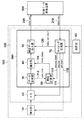
図1に基づき、第1実施形態の説明を行う。尚、説明では対象物の位置を計測するエンコーダを例として挙げるが、対象物の角度を計測するエンコーダの場合にも同様に適用可能である。図1は第1実施形態のエンコーダに係る信号処理系の構成を示す。エンコーダ100は、対象物の位置を計測する。計測データ収集装置(上位システム)500は、エンコーダ100が計測した対象物の位置を示すデータを取得する。上位システム500は、例えば、産業用装置や加工機の場合には位置決め制御を行う制御機器であり、計測装置の場合にはデータの収集や解析を行う装置である。
[First Embodiment]
The first embodiment will be described with reference to FIG. In the description, an encoder that measures the position of an object is taken as an example, but the present invention can be similarly applied to an encoder that measures the angle of an object. FIG. 1 shows a configuration of a signal processing system according to the encoder of the first embodiment. The
上位システム500は、data_req信号(指令信号)210をエンコーダ100に周期的に送信し、data_req信号のタイミングで計測された位置のデータをdata_out信号220として受信する。これまでの機器では、data_req信号210の周期は1ms〜100μs、すなわち周波数は1kHz〜10kHz程度で、例えば、位置決め制御の制御帯域は10〜100Hz程度であった。
The
しかしながら、産業用装置や加工機又は計測装置では、位置又は角度のより高精度な計測が必要とされ、その上、対象物の移動速度又は回転速度は高速化している。そのため、対象物の位置又は角度をより高速でかつ高精度に計測することが必要とされている。例えば、data_req信号210による計測周期を10μs、すなわち周波数を100kHzとし、位置決め制御の制御帯域を100Hz〜1kHz程度とする場合を考える。
However, industrial devices, processing machines, or measuring devices require more accurate measurement of position or angle, and in addition, the moving speed or rotational speed of an object is increased. Therefore, it is necessary to measure the position or angle of the object at higher speed and with higher accuracy. For example, consider a case where the measurement cycle by the
検出部10は、対象物からの変調光を検出して検出信号を出力する。エンコーダ100の光学系の構成を図2に示す。光源12は、例えばLEDである。コリメータレンズ14は、LEDから射出されてコリメータレンズ14に入射した光を平行光とし、スケール16に出射する。アブソリュートエンコーダの場合、擬似乱数コード、例えばM系列の巡回符号がスケール16に形成され、透過又は反射によりスケール16を出射した光は擬似乱数コードによる光強度を有する。この光を検出部10で受光する。この検出部10は、例えば、CMOSイメージセンサやCCDセンサ等の光電変換素子である。受光強度は図2の下図に示すような擬似乱数コードを反映した強弱信号となる。なお、検出部10およびスケール16は、上述の構成のものには限定されず、例えば、磁気スケールおよびそれに対応する検出部であってもよく、公知の検出部およびスケールに置換可能である。
The
エンコーダ100がインクリメンタルエンコーダの場合は、等間隔で透過膜又は反射膜のマークがスケール16に形成され、マークで変調された光の受光強度が一定周期の正弦波となる。位置を計測するリニアエンコーダの場合、スケール16は直線状のものであるが、角度を計測するロータリーエンコーダの場合には、スケール16は同心円状である。移動又は回転する対象物に対して光源12と光電変換素子10とを取り付け、基準となる固定側にスケール16が取り付けることができる。それとは逆に、対象物にスケール16を取り付け、固定側に光源12と光電変換素子10とを取り付けてもよい。
When the
図1に戻り説明を続ける。検出部10は、光電変換素子10に続き、電流/電圧変換器が構成され、受光強度を電圧信号に変換する。必要に応じて後段に電圧増幅器を置き、電圧信号を所定の電圧レベルまで増幅する。A/D変換器20は、検出部10からの検出信号をA/D変換し、アナログ信号をデジタル信号に変換する。デジタル信号処理部200は、A/D変換器20からのデジタル信号を処理して対象物の位置を示すデータを生成し、補正し、補正されたデータを出力する。デジタル信号処理部200は、FPGA(Field Programable Allay)又はDSP(Digital Signal Processor)等の高速なデジタル信号処理器により構成される。A/D変換器20およびデジタル信号処理部200は、検出部10から出力された検出信号に基づいて対象物の位置を示すデータを生成し、補正し、補正されたデータを出力する処理部150を構成している。
Returning to FIG. Following the
データ生成部(生成部)30は、A/D変換器20からのデジタル信号に基づいて対象物の位置を示すデータを生成する。例えば、アブソリュートエンコーダの場合、データ生成部30は、図2に示した擬似乱数コードを反映した強弱信号より、0と1で表される擬似乱数コードを再生する。次いで、データ生成部30は、再生した擬似乱数コードを、データ生成部30内に保有する不図示の擬似乱数コードに対する絶対位置の参照テーブルと照合し、検出された擬似乱数コードに対応する絶対位置を求める。擬似乱数コードの位相を細かく分割することによりエンコーダ100の計測分解能と精度を向上させることが可能である。
The data generation unit (generation unit) 30 generates data indicating the position of the object based on the digital signal from the A /
タイミング生成部70は、発振器80と計測データ収集装置500からのdata_req信号210を受信してmeas_start信号110、meas信号111、ad_start信号116、data_out_start信号120を生成する。時間計測部(遅延時間計測部)60は、タイミング生成部70からのmeas_start信号110とデータ生成部30からのcalc_end信号112とにより、位置データ220を補正するための遅延時間を計測する。
The
エンコーダ100における各部の動作タイミングと信号処理を図3及び図4を参照して説明する。図4は各部の動作タイミングを表すタイミング図である。data_req信号は、計測データ収集装置500からのdata_req信号210であり、その所定の周期Treqを10μs、すなわち周波数を100kHzとする。
The operation timing and signal processing of each part in the
clk信号は、タイミング生成部70により生成されるクロック信号である。図3の発振器80からの基準信号よりクロック信号生成部72にて、より高速なclk信号が生成される。クロック信号生成部72は、例えば、PLL(Phase Locked Loop)により構成され、例えば、発振器80からの10MHzの基準信号より200MHzのclk信号を生成する。クロック信号生成部72は、必要に応じて、100MHz、50MHz、25MHz等のclk信号を生成し、デジタル信号処理部200の各演算で必要とされるクロック信号を供給する。
The clk signal is a clock signal generated by the
図3の同期タイミング信号生成部76は、クロック信号生成部72からのclk信号とdata_req信号210より、検出部10の検出の開始信号であるmeas_start信号110を生成する。計測データ収集装置500とエンコーダ100は、クロックが異なる非同期動作であるため、この同期タイミング信号生成部76により計測データ収集装置500からのdata_req信号210を、デジタル信号処理部200のclk信号のタイミングに合わせる。
The synchronization
図4の4つのdata_req信号data_req_1〜data_req_4の周期Treqは、例えば10μsで一定である。しかし、data_req信号は、clk信号とは非同期である。そのため、clk信号と同期を取った後のmeas_start信号110による実際の計測周期Tspは、data_req信号に対して最大でclk信号の1クロック分だけずれる可能性がある。例えば、clk信号の周波数を200MHz、周期を5nsとすると、最大で5nsのずれが生じる可能性がある。しかし、後述する対象物の移動速度による計測位置誤差は極めて小さいため、同期タイミング信号生成部76における同期ずれの影響は無視できる。
The period Treq of the four data_req signals data_req_1 to data_req_4 in FIG. 4 is constant, for example, 10 μs. However, the data_req signal is asynchronous with the clk signal. Therefore, the actual measurement period Tsp by the
同期タイミング信号生成部76は、meas_start信号110の他にmeas信号111を生成する。meas信号111は、meas_start信号110と同期し、検出部10の光電変換素子の受光時間Tmeasを決定する。受光時間は、光電変換素子の感度や光源12の発光強度、およびスケール16の透過率又は反射率により異なる。しかし、計測データ収集装置500からのdata_req信号210の計測周期Treqが例えば10μsの場合、受光時間Tmeasは10μs未満でなければならない。つまり、検出部10の光電変換素子の受光時間Tmeasは、計測データ収集装置500からのdata_req信号210の計測周期Treqに対して、Tmeas<Treqとなるように設定される。
The synchronization
検出部10の検出に起因する検出遅延時間について考える。検出部10の光電変換素子は、スケール16からの透過光又は反射光を、受光時間Tmeasの間、積分する。この積分時間の間に、対象物が速度V(m/s)で移動したとする。そうすると、検出部10が変調光の検出に要する受光時間Tmeasの間に対象物が移動したことに伴う計測位置ずれが生じる。平均的な位置ずれ、すなわち受光時間Tmeasによって発生する検出遅延時間による位置誤差(m)は、例えば、下式1で表される。
検出遅延時間による位置誤差(m)=移動速度V(m/s)×受光時間Tmeas/2(s)・・・(1)
Consider the detection delay time resulting from the detection of the
Position error due to detection delay time (m) = moving speed V (m / s) × light receiving time Tmeas / 2 (s) (1)
例えば、計測周期Treq=10μs、受光時間Tmeas=8μs、移動速度V=1m/sの場合、式1より、検出遅延時間による位置誤差は4μmとなる。高精度な位置計測では、例えば1μm以下の精度が要求されるため、この位置誤差を無視することはできない。
For example, when the measurement cycle Treq = 10 μs, the light receiving time Tmeas = 8 μs, and the moving speed V = 1 m / s, the position error due to the detection delay time is 4 μm from
この検出遅延時間の影響は、エンコーダ100の位置出力を評価して実測により求めてもよいし、シミュレーションにより求めてもよいが、ここでは、簡単のため、下式2で表す。すなわち、検出遅延時間は、検出部10による変調光の1回の検出に要する時間の半分となる。
検出遅延時間(s)=受光時間Tmeas/2(s)・・・(2)
The influence of this detection delay time may be obtained by actual measurement by evaluating the position output of the
Detection delay time (s) = light reception time Tmeas / 2 (s) (2)
図4中のmeas_1等のmeas信号は、計測データ収集装置500からのdata_req_1等に応じて生成された信号であり、検出部10は、meas信号に基づいて変調光を検出する。同期タイミング信号生成部76は、ad_start信号116も生成する。図4を参照すると、meas_1信号により検出部10から出力されたアナログの検出信号を、それに続くAD_1のタイミングでA/D変換器20によりデジタル信号に変換する。次のmeas_2信号による計測は、meas_1の計測後に引き続き行われる。
A meas signal such as meas_1 in FIG. 4 is a signal generated according to data_req_1 from the measurement
第1実施形態では、計測データ収集装置500からのdata_req信号が高速な計測周期Treqを有していても正確な位置計測を行うために、検出部10は、A/D変換やその後の信号処理の実行と並行して新たな計測を行う。図4では、AD_1や、AD_1からの信号に基づくデータ生成部30での演算calc_1と並行して次の計測meas_2が行われ、AD_2やcalc_2と並行して次のmeas_3が行われ、AD_3やcalc_3と並行して次のmeas_4が行われる。例えば、meas_1信号による計測の後、AD_1によるA/D変換とその後の信号処理が行われ、それらが終了した後に次の計測をmeas_2信号により行うと、計測周期Tspが非常に長いものとせざるを得ない。よって、計測データ収集装置500からのdata_req信号が高速な計測周期Treqの場合には対応不可能となる。
In the first embodiment, in order to perform accurate position measurement even when the data_req signal from the measurement
図3の時間計測部60の動作を図4のタイミングを参照しながら説明する。時間計測部60は、チャンネル切り替え部62にてタイミング生成部70よりmeas_start信号110を受信する。例えば、data_req_1をトリガーとしてclk信号に同期させたmeas_1の計測開始のタイミングに同期して第1時間計測部63による遅延時間の計測を開始させる。また、次のdata_req_2によるmeas_2の計測の開始のタイミングに同期して第2時間計測部64による遅延時間の計測を開始させる。更に、次のdata_req_3によるmeas_3の計測の開始のタイミングに同期して第3時間計測部65の遅延時間の計測を開始させる。遅延時間の計測は、専用のタイマー又はカウンターであってもよいし、一つのタイマー又はカウンターを動作させておいて、計測の開始のタイミングでその値を読み込んで保持し、計測終了時の値との差により遅延時間の計測を行ってもよい。このように、時間計測部60では、計測周期による計測の開始の度に遅延時間の計測を開始し、複数の遅延時間の計測を並行して実行する。
The operation of the
図4を参照すると、meas_1の計測の開始のタイミングに同期してtime_meas_1の遅延時間の計測を開始する。同様にmeas_2の計測の開始のタイミングに同期してtime_meas_2の遅延時間の計測を開始し、meas_3の計測の開始のタイミングに同期してtime_meas_3の遅延時間の計測を開始する。 Referring to FIG. 4, the measurement of the delay time of time_meas_1 is started in synchronization with the start timing of measurement of meas_1. Similarly, measurement of the delay time of time_meas_2 is started in synchronization with the start timing of measurement of meas_2, and measurement of the delay time of time_meas_3 is started in synchronization with the start timing of measurement of meas_3.
meas_1によるアナログデータは、AD_1を通してデジタル信号に変換され、データ生成部30にてcalc_1を通して位置の演算が行われる。位置の演算が終了すると、データ生成部30からcalc_end信号112が出力され、時間計測部60のチャンネル切り替え部62に入力される。この信号により、meas_1の位置の演算が終了したことが通知され、チャンネル切り替え部62では、第1時間計測部63の遅延時間の計測を停止可能な状態とし、その後に入力される計測の開始のタイミングに同期して遅延時間の計測を停止する。図4の例では、meas_3の計測の開始タイミングに同期して第1時間計測部63の遅延時間の計測time_meas_1を停止させる。time_meas_2、time_meas_3も同様にして、データ生成部30からのcalc_end信号112とその後に入力される計測の開始のタイミングに同期して遅延時間の計測を停止させる。ここで、time_meas_1による遅延時間の計測値をTtm_1とする。
The analog data by meas_1 is converted into a digital signal through AD_1, and the position of the data is calculated by calc_1 in the
図4のdata_req_3に対する位置データの出力は、data_req信号の直前に位置の演算が終了しているtime_meas_1の位置データが用いられる。一方、data_req_3のタイミングでは、time_meas_2はまだ位置の演算が終了していないため、遅延時間の計測が継続して行われる。また、time_meas_3は直後のmeas_3信号により遅延時間の計測が開始される。本実施形態では、データの生成後に受信する最初のdata_req_信号の受信に応じて補正データ出力部50は補正データを出力している。しかし、補正データの出力タイミングは、データの生成後に受信する最初のdata_req_信号を受信するタイミングでなくてもかまわない。
For the output of the position data for data_req_3 in FIG. 4, the position data of time_meas_1 for which the position calculation has been completed immediately before the data_req signal is used. On the other hand, at the timing of data_req_3, since the calculation of the position of time_meas_2 has not been completed yet, the delay time is continuously measured. Also, for time_meas_3, measurement of the delay time is started by the immediately following meas_3 signal. In the present embodiment, the correction
計測データ収集装置500からのdata_req信号210に対する位置データの出力は、そのdata_req信号のタイミングにおける位置データが保証されていなければならない。本発明では、計測周期が検出部10とデータ生成部30と補正部40と補正データ出力部50の処理に要する時間の和より短い高速な計測を行う場合においても正確な位置計測を行うことを可能とする。そのため、data_req信号210に対する位置データは、それ以前のdata_req信号210に同期して計測されたデータを用い、時間計測部60の計測開始から位置データを出力するdata_req信号210までの時間を遅延時間として計測する。計測された遅延時間は、補正時間出力部66に入力される。補正時間出力部66は、この計測された遅延時間に対し、回路符号67のΔTdにより検出部10における検出遅延時間だけ補正を行う。
For the output of position data for the data_req signal 210 from the measurement
図4を参照すると、data_req_3のタイミングに対して出力される位置データはmeas_1で計測されたデータであり、遅延時間は先に述べたTtm1である。すなわち、出力される位置データは、時間Ttm1だけ過去に計測されたデータである。しかしながら、先に述べたように、検出部10における検出遅延時間のため、Ttm1に対して実際に計測されたデータは遅れている。この検出遅延時間を考慮すると、補正された遅延時間は下式3により与えられる。
補正された遅延時間=計測された遅延時間−検出部による検出遅延時間・・・(3)
このように、実際に補正に用いられる遅延時間は、計測された遅延時間と検出遅延時間との差となる。この検出遅延時間が差し引かれた補正後の遅延時間はtime_delay信号114として補正部40に入力される。例えば、図4の例では、Ttm1=20μsであり、検出遅延時間は、(2)式を用いると、ΔTd/2=4μsである。従って、(3)式による補正後の遅延時間は16μsとなる。
Referring to FIG. 4, the position data output with respect to the timing of data_req_3 is data measured by meas_1, and the delay time is Ttm1 described above. That is, the output position data is data measured in the past for the time Ttm1. However, as described above, due to the detection delay time in the
Corrected delay time = measured delay time−detection delay time by the detection unit (3)
Thus, the delay time actually used for correction is the difference between the measured delay time and the detected delay time. The corrected delay time obtained by subtracting the detection delay time is input to the
図2の補正部40は、データ生成部30からの位置データと時間計測部60からの補正された遅延時間すなわちtime_delay信号114とより位置データを補正する。式1と同様にして、対象物の移動速度により位置誤差が発生する。そのため、補正部40は、移動速度と補正された遅延時間とを乗算した量だけ位置データを補正する。
位置データの補正量(m)=移動速度V(m/s)×補正された遅延時間(s)・・・(4)
The
Position data correction amount (m) = moving speed V (m / s) × corrected delay time (s) (4)
移動速度は、次式5を用いて位置データの単位時間当りの変化量より算出される。
移動速度V(m/s)={前回サンプル位置データ(m)−今回サンプル位置データ(m)}/計測周期(s)・・・(5)
The moving speed is calculated from the amount of change per unit time of the position data using the following equation (5).
Movement speed V (m / s) = {previous sample position data (m) −current sample position data (m)} / measurement cycle (s) (5)
例えば、補正された遅延時間が16μsで移動速度が1m/sの場合、(4)式より、16μmだけ位置データの補正が行われる。尚、先に述べた同期タイミング信号生成部76における5ns程度の同期ずれによる位置誤差は、移動速度が1m/sの場合に5nmであり、必要とされるμm前後の位置精度に対して極めて小さく、その影響は無視できる。
For example, when the corrected delay time is 16 μs and the moving speed is 1 m / s, the position data is corrected by 16 μm from the equation (4). Note that the position error due to the synchronization shift of about 5 ns in the synchronization timing
補正部40で位置データが補正され、補正データ出力部(出力部)50にてタイミング生成部70からのdata_out_start信号120によりdata_out信号220を位置データとして出力する。図4を参照すると、data_req_3に対する位置データはmeas_1データによる位置の演算と位置データの補正が行われ、data_out_1として計測データ収集装置500に送信される。同様に、data_req_4に対する位置データはmeas_2データによる位置の演算と位置データの補正が行われ、data_out_2として計測データ収集装置500に送信される。
The
このように、第1実施形態では、計測周期が検出部10とデータ生成部30と補正部40と補正データ出力部50の処理に要する時間の和より短い高速な計測にも対応できる。すなわち、検出部10は、データ生成部30の実行と並行して新たな計測を行う。時間計測部60は、計測開始の度に遅延時間の計測を開始して複数の遅延時間の計測を並行して実行し、データ生成部30での演算が終了した後に入力されたdata_req信号により遅延時間の計測を終了する。時間計測部60は、更に計測された遅延時間から検出遅延時間を差し引いて遅延時間を補正する。補正部40は、位置データの時間変化量より速度に相関した信号を算出して補正された遅延時間との積により位置データを補正する。これにより、上位システム500からの計測data_req信号により高速な位置又は角度の計測を行う場合においても計測における遅延時間を計測して位置データを補正し、高速かつ高精度な位置又は角度の計測を行うことが可能となる。
Thus, in the first embodiment, it is possible to cope with high-speed measurement in which the measurement cycle is shorter than the sum of the time required for the processing of the
〔第2実施形態〕
次に、第2実施形態の説明を行う。第2実施形態では、第1実施形態に対して時間計測部60aとタイミング生成部70aが異なる。同様の動作を行う部分は回路符号を同じとし、その説明を割愛する。図5は第2実施形態における時間計測部60aとタイミング生成部70aを表す構成ブロック図であり、図6はエンコーダ100の各部における動作タイミングを表す図である。
[Second Embodiment]
Next, the second embodiment will be described. In 2nd Embodiment, the
タイミング信号生成部76aは、クロック信号生成部72からのclk信号により、meas_start信号110と、検出部10の受光時間Tmeasを決定するmeas信号111と、A/D変換を行うためのad_start信号116を生成する。第1の実施形態では、data_req信号210を、デジタル信号処理部200のクロック信号のタイミングに合わせるために、クロック信号生成部72で生成したclk信号と同期を取ってmeas_start信号110を生成した。しかし、第2の実施形態では、計測データ収集装置500からのdata_req信号210とは独立に、クロック信号生成部72で生成したclk信号により上記各種信号を生成する。同期回路74は、計測データ収集装置500からのdata_req信号210をクロック信号生成部72で生成したclk信号により同期を取り、data_req’信号113を生成し、時間計測部60aのチャンネル切り替え部62aに出力する。
The
図6を参照すると、計測データ収集装置500からのdata_req_3をclk信号により同期を取り、data_req_3’信号を生成する。例えば、data_req_1〜data_req_4の計測周期は、Treq=10μsである。clk信号と同期を取った後のdata_req’信号113は、data_req信号に対して最大でclk信号の1クロック分だけずれる可能性がある。例えば、clk信号の周波数を200MHz、周期を5nsとすると、最大で5nsのずれが生じる可能性があるが、先に述べたように5nsの時間ずれは十分に小さいためその影響は無視できる。
Referring to FIG. 6, data_req_3 from the measurement
一方、計測データ収集装置500からのdata_req信号210とは独立に生成されたmeas信号111の計測周期Tspは、前記Treqと同期しておらず、周期も一致していない。第2実施形態では、計測周期が検出部10とデータ生成部30と補正部40と補正データ出力部50の処理に要する時間の和より短い高速な計測を行う場合においても正確な位置計測を行うことを可能とする。そのため、計測データ収集装置500からのdata_req信号による計測周期Treqに対し、これとは独立に生成され、実際に行われる計測の周期Tspを、Tsp≦Treqとする必要がある。それ以外の動作、すなわち、検出部10、A/D変換器20、データ生成部30、及び補正部40と補正データ出力部50の動作は第1実施形態と同様である。
On the other hand, the measurement cycle Tsp of the meas signal 111 generated independently of the data_req signal 210 from the measurement
時間計測部60aのチャンネル切り替え部62aは、meas_1〜meas_3信号により第1時間計測部63、第2時間計測部64、第3時間計測部65での時間計測を開始する。例えば、図6を参照すると、位置演算の終了信号であるcalc_1がチャンネル切り替え部62aに入力されるとする。そうすると、time_meas_1による第1時間計測部63の遅延時間の計測が停止可能な状態とされ、その後に入力されるdata_req_3’により遅延時間の計測が停止される。time_meas_2も同様にして、calc_2によりtime_meas_2による第2時間計測部64の遅延時間の計測を停止可能な状態とし、その後に入力されるdata_req_4’により遅延時間の計測を停止する。
The
計測された遅延時間は、第1実施形態と同様に、検出部10における検出遅延時間が差し引かれた後、補正部40にて位置データを補正する。補正された位置データは、補正データ出力部50よりタイミング生成部70aからのdata_out_start信号120によりdata_out信号220の位置データとして出力される。尚、data_out_start信号120は、図5に示すように、同期回路74にてdata_req信号210とクロック信号生成部72からのclk信号により生成される。
As in the first embodiment, the measured delay time is corrected by the
図6を参照すると、data_req_3に対する位置データはmeas_1データによる位置の演算と位置データの補正が行われ、data_out_1として計測データ収集装置500に送信される。同様に、data_req_4に対する位置データはmeas_2データによる位置の演算と位置データの補正が行われ、data_out_2として計測データ収集装置500に送信される。
Referring to FIG. 6, the position data for data_req_3 is subjected to position calculation and position data correction based on meas_1 data, and is transmitted to the measurement
このように、第2実施形態においても、計測周期が検出部10とデータ生成部30と補正部40と補正データ出力部50の処理に要する時間の和より短い高速な計測にも対応できる。すなわち、検出部10は、データ生成部30の実行と並行して新たな計測を行う。時間計測部60aは、計測開始の度に遅延時間の計測を開始して複数の遅延時間の計測を並行して実行し、データ生成部30での演算が終了した後に入力された計測データ取得信号により遅延時間の計測を終了して遅延時間を決定する。時間計測部60aは、更に計測された遅延時間から検出遅延時間を差し引いて遅延時間を補正する。補正部40は、位置データの時間変化量より速度に相関した信号を算出して補正された遅延時間との積により位置データを補正する。これにより、上位システム500からの計測data_req信号により高速な位置又は角度の計測を行う場合においても計測における遅延時間を計測して位置データを補正し、高速かつ高精度な位置又は角度の計測を行うことが可能となる。
As described above, also in the second embodiment, it is possible to cope with high-speed measurement in which the measurement cycle is shorter than the sum of the time required for the processing of the
本発明では、上位システム500からの計測data_req信号により高速な位置又は角度の計測を行う場合においても計測における遅延時間を計測して位置データを補正し、高速かつ高精度な位置又は角度の計測を行うことが可能となる。
In the present invention, even when a high-speed position or angle is measured by the measurement data_req signal from the
Claims (10)
前記スケールからの信号の検出を行って検出信号を出力する検出部と、
前記検出信号に基づいて前記スケールの位置又は角度を示すデータの生成を行う生成部と、
前記検出部による前記検出の開始から前記生成部による前記生成の終了までの時間と、前記検出部による前記検出に要する検出遅延時間とによって決定される遅延時間を得る遅延時間取得部と、
前記遅延時間取得部によって取得された遅延時間に応じて、前記データを補正する補正部と、
前記指令信号の受信に従って、前記補正部により補正された前記データを出力する出力部と、を備えており、
前記遅延時間取得部は、複数の前記遅延時間を並行して取得する、
ことを特徴とするエンコーダ。 An encoder that outputs a measurement value of a scale position or angle according to a command signal,
A detection unit that detects a signal from the scale and outputs a detection signal;
A generating unit that generates data indicating the position or angle of the scale based on the detection signal;
Time from the start of the detection by the detector until the end of the generation by the generator, and the detecting unit by obtaining a detection delay time and the result delay time determined necessary for the detection delay time acquiring unit,
A correction unit that corrects the data according to the delay time acquired by the delay time acquisition unit;
An output unit that outputs the data corrected by the correction unit in accordance with the reception of the command signal,
The delay time acquisition unit acquires a plurality of the delay times in parallel.
An encoder characterized by that.
前記エンコーダは、前記検出信号をA/D変換するA/D変換器を含む、ことを特徴とする請求項1ないし7のいずれか1項に記載のエンコーダ。 The detection unit includes a photoelectric conversion element,
The encoder according to any one of claims 1 to 7, wherein the encoder includes an A / D converter that performs A / D conversion on the detection signal.
前記スケールからの信号の検出を行って検出信号を出力する検出工程と、
前記検出信号に基づいて前記スケールの位置又は角度を示すデータの生成を行う生成工程と、
前記検出の開始から前記生成の終了までの時間と、前記検出に要する検出遅延時間とによって決定される遅延時間を得る取得工程と、
前記取得工程で得られた前記遅延時間に応じて、前記データを補正する補正工程と、
前記指令信号の受信に従って、前記補正工程で補正された前記データを出力する出力工程と、を含み、
前記取得工程では、複数の前記遅延時間を並行して取得する、
ことを特徴とする方法。 A method of outputting a measurement value of a scale position or angle according to a command signal,
A detection step of detecting a signal from the scale and outputting a detection signal;
A generation step of generating data indicating the position or angle of the scale based on the detection signal;
Time until the end of the generation from the start of the detection, an acquisition step of obtaining a delay time detection delay time and the thus determined required for the detection,
A correction step of correcting the data according to the delay time obtained in the acquisition step;
Outputting the data corrected in the correction step according to reception of the command signal, and
In the acquisition step, a plurality of the delay times are acquired in parallel.
A method characterized by that.
Priority Applications (3)
| Application Number | Priority Date | Filing Date | Title |
|---|---|---|---|
| JP2013078091A JP6341631B2 (en) | 2013-04-03 | 2013-04-03 | Encoder |
| US14/231,107 US10072950B2 (en) | 2013-04-03 | 2014-03-31 | Encoder and method of outputting measurement value of position or angle |
| EP14163415.4A EP2787326B1 (en) | 2013-04-03 | 2014-04-03 | Encoder and method of outputting measurement value of position or angle |
Applications Claiming Priority (1)
| Application Number | Priority Date | Filing Date | Title |
|---|---|---|---|
| JP2013078091A JP6341631B2 (en) | 2013-04-03 | 2013-04-03 | Encoder |
Publications (3)
| Publication Number | Publication Date |
|---|---|
| JP2014202568A JP2014202568A (en) | 2014-10-27 |
| JP2014202568A5 JP2014202568A5 (en) | 2016-05-26 |
| JP6341631B2 true JP6341631B2 (en) | 2018-06-13 |
Family
ID=50424124
Family Applications (1)
| Application Number | Title | Priority Date | Filing Date |
|---|---|---|---|
| JP2013078091A Active JP6341631B2 (en) | 2013-04-03 | 2013-04-03 | Encoder |
Country Status (3)
| Country | Link |
|---|---|
| US (1) | US10072950B2 (en) |
| EP (1) | EP2787326B1 (en) |
| JP (1) | JP6341631B2 (en) |
Families Citing this family (7)
| Publication number | Priority date | Publication date | Assignee | Title |
|---|---|---|---|---|
| JP6737018B2 (en) * | 2016-07-08 | 2020-08-05 | オムロン株式会社 | Optical measuring device |
| JP2018036090A (en) * | 2016-08-30 | 2018-03-08 | キヤノンプレシジョン株式会社 | Encode and device including the same |
| US9877042B1 (en) * | 2017-05-26 | 2018-01-23 | Mitutoyo Corporation | Position encoder sample timing system |
| JP6659656B2 (en) * | 2017-12-01 | 2020-03-04 | ファナック株式会社 | Encoder and control system |
| WO2019169182A1 (en) * | 2018-02-28 | 2019-09-06 | DWFritz Automation, Inc. | Trigger management device for measurement equipment |
| JP6836563B2 (en) | 2018-09-25 | 2021-03-03 | ファナック株式会社 | Encoder and encoder control system |
| CN112306112B (en) * | 2020-10-09 | 2023-11-24 | 武汉华之洋科技有限公司 | Turntable/swinging table with high-frequency angle measuring mechanism and angle measuring method |
Family Cites Families (17)
| Publication number | Priority date | Publication date | Assignee | Title |
|---|---|---|---|---|
| US4492465A (en) * | 1980-12-18 | 1985-01-08 | The Boeing Company | Retro-reflective electro-optical angle measuring system |
| US4868474A (en) * | 1986-11-20 | 1989-09-19 | Westinghouse Electric Corp. | Multiprocessor position/velocity servo control for multiaxis digital robot control system |
| JPH05240631A (en) * | 1992-02-27 | 1993-09-17 | Yokogawa Electric Corp | Optical encoder |
| JP3518029B2 (en) * | 1994-05-09 | 2004-04-12 | 三菱電機株式会社 | Servo system controller |
| US6630659B1 (en) * | 1994-06-01 | 2003-10-07 | Stridsberg Innovation Ab | Position transducer |
| JP3367260B2 (en) | 1995-03-24 | 2003-01-14 | 三菱電機株式会社 | Encoder device and servo motor control device |
| US5717512A (en) * | 1996-05-15 | 1998-02-10 | Chmielewski, Jr.; Thomas A. | Compact image steering and focusing device |
| EP1270311B1 (en) * | 1997-05-02 | 2005-09-14 | Ats Automation Tooling Systems Inc. | Modular conveyor system having multiple moving elements under independent control |
| US6470291B1 (en) * | 1998-09-25 | 2002-10-22 | Seagate Removable Storage Solutions Llc | Velocity feedback measurement method |
| JP3772121B2 (en) * | 2002-02-28 | 2006-05-10 | ファナック株式会社 | Encoder signal processing device |
| US6639529B1 (en) | 2002-05-14 | 2003-10-28 | Mitutoyo Corporation | System and method for delay calibration in position encoders |
| JP2005221429A (en) * | 2004-02-06 | 2005-08-18 | Mitsutoyo Corp | Position correction method, position correction apparatus, and feeder using the same |
| JP4953714B2 (en) * | 2005-08-11 | 2012-06-13 | 株式会社ミツトヨ | Encoder output interpolation method and interpolation circuit |
| JP2008032562A (en) * | 2006-07-28 | 2008-02-14 | Ntn Corp | Rotation detector, and bearing with rotation detector |
| US8095000B2 (en) * | 2007-02-15 | 2012-01-10 | Panasonic Corporation | Camera system |
| JP5545360B2 (en) | 2010-04-02 | 2014-07-09 | 株式会社安川電機 | Signal processing apparatus, encoder and motor system |
| DE102011079961A1 (en) * | 2011-07-28 | 2013-01-31 | Dr. Johannes Heidenhain Gmbh | Apparatus and method for angle measurement |
-
2013
- 2013-04-03 JP JP2013078091A patent/JP6341631B2/en active Active
-
2014
- 2014-03-31 US US14/231,107 patent/US10072950B2/en active Active
- 2014-04-03 EP EP14163415.4A patent/EP2787326B1/en active Active
Also Published As
| Publication number | Publication date |
|---|---|
| EP2787326A1 (en) | 2014-10-08 |
| JP2014202568A (en) | 2014-10-27 |
| US10072950B2 (en) | 2018-09-11 |
| US20140299754A1 (en) | 2014-10-09 |
| EP2787326B1 (en) | 2018-12-05 |
Similar Documents
| Publication | Publication Date | Title |
|---|---|---|
| JP6341631B2 (en) | Encoder | |
| JP6436616B2 (en) | Measuring device, measuring method, and processing device | |
| CN105634718B (en) | Apparatus and method for signal synchronization | |
| JP5753449B2 (en) | Lightwave distance measuring method and lightwave distance apparatus | |
| US6912476B2 (en) | Position measuring device and method for determining a position | |
| JPH10339650A (en) | Device and method for automatically correcting scanning signal including error of increment position measuring device | |
| US11860037B2 (en) | Interferometer movable mirror position measurement apparatus and fourier transform infrared spectroscopy | |
| JP4138138B2 (en) | Absolute displacement measuring device | |
| CN104101369A (en) | Position detection apparatus | |
| JP2011145109A (en) | Electro-optical distance measuring device | |
| KR101223953B1 (en) | Self Temperature Compensated Precision Event timer using Standard Time reference Frequency | |
| JP4202751B2 (en) | Method for position setting and position measuring device for carrying out this method | |
| JP6583738B2 (en) | Phase measuring device and equipment to which the phase measuring device is applied | |
| JP6629376B2 (en) | Method of operating a coordinate measuring device | |
| JP2015087193A (en) | Position detection device and lens device including the same and imaging device | |
| JP2003254784A (en) | Method and device for calibrating displacement | |
| JP4230244B2 (en) | Shape measuring device | |
| JPS61221616A (en) | Optical measuring method for fine displacement | |
| KR100489475B1 (en) | Apparatus for calculating moving displacement for use in I/Q heterodyne interference system | |
| JP2003269997A (en) | Self-calibrating type angle detector | |
| JP2019203709A (en) | Position measuring device | |
| JP2005024523A (en) | Range finder and projector having range finder | |
| JP2001330479A (en) | Origin signal generator | |
| JPH05340976A (en) | Measuring unit | |
| JP2003214836A (en) | Relative displacement quantity detector |
Legal Events
| Date | Code | Title | Description |
|---|---|---|---|
| A521 | Request for written amendment filed |
Free format text: JAPANESE INTERMEDIATE CODE: A523 Effective date: 20160404 |
|
| A621 | Written request for application examination |
Free format text: JAPANESE INTERMEDIATE CODE: A621 Effective date: 20160404 |
|
| A977 | Report on retrieval |
Free format text: JAPANESE INTERMEDIATE CODE: A971007 Effective date: 20170118 |
|
| A131 | Notification of reasons for refusal |
Free format text: JAPANESE INTERMEDIATE CODE: A131 Effective date: 20170227 |
|
| A521 | Request for written amendment filed |
Free format text: JAPANESE INTERMEDIATE CODE: A523 Effective date: 20170427 |
|
| A131 | Notification of reasons for refusal |
Free format text: JAPANESE INTERMEDIATE CODE: A131 Effective date: 20170925 |
|
| A521 | Request for written amendment filed |
Free format text: JAPANESE INTERMEDIATE CODE: A523 Effective date: 20171124 |
|
| TRDD | Decision of grant or rejection written | ||
| A01 | Written decision to grant a patent or to grant a registration (utility model) |
Free format text: JAPANESE INTERMEDIATE CODE: A01 Effective date: 20180416 |
|
| A61 | First payment of annual fees (during grant procedure) |
Free format text: JAPANESE INTERMEDIATE CODE: A61 Effective date: 20180515 |
|
| R151 | Written notification of patent or utility model registration |
Ref document number: 6341631 Country of ref document: JP Free format text: JAPANESE INTERMEDIATE CODE: R151 |