JP2008242187A - Onboard camera - Google Patents
Onboard camera Download PDFInfo
- Publication number
- JP2008242187A JP2008242187A JP2007084100A JP2007084100A JP2008242187A JP 2008242187 A JP2008242187 A JP 2008242187A JP 2007084100 A JP2007084100 A JP 2007084100A JP 2007084100 A JP2007084100 A JP 2007084100A JP 2008242187 A JP2008242187 A JP 2008242187A
- Authority
- JP
- Japan
- Prior art keywords
- lens cover
- camera
- dew condensation
- condensation
- water
- Prior art date
- Legal status (The legal status is an assumption and is not a legal conclusion. Google has not performed a legal analysis and makes no representation as to the accuracy of the status listed.)
- Pending
Links
Images


Abstract
Description
本発明は、車両の周囲を撮像するための車載用カメラに関する。 The present invention relates to an in-vehicle camera for imaging the surroundings of a vehicle.
従来、車両の周囲を撮像する安全確認用の車載用カメラが知られている。この種の車載用カメラでは、車両に取り付けられた筐体内に収容されたカメラ本体と、このカメラ本体の前面側に配置されたレンズカバーとを備える。このため、外気温とカメラ本体側の温度との温度差が大きい場合、このレンズカバーのガラス面が結露することにより、このガラス面が曇り、カメラの視界が悪くなるという問題がある。この結露は、レンズカバーの外側に生じる場合と、レンズカバーの内側に生じる場合とがある。 2. Description of the Related Art Conventionally, a vehicle-mounted camera for safety confirmation that captures an image of the surroundings of a vehicle is known. This type of in-vehicle camera includes a camera body housed in a housing attached to the vehicle, and a lens cover disposed on the front side of the camera body. For this reason, when the temperature difference between the outside air temperature and the temperature on the camera body side is large, there is a problem that the glass surface of the lens cover is dewed and the glass surface becomes cloudy, resulting in poor visibility of the camera. This condensation may occur outside the lens cover or inside the lens cover.
レンズカバーの外側に結露が生じる場合とは、外気温がカメラ本体側の温度よりも高い場合である。この場合、カメラ本体の電源が入れられるとカメラ本体側の温度が高くなるので、時間の経過に従って結露の問題は自然に解消されることになる。また、レンズカバーの外側であれば、人為的に結露水を拭き取ることも可能である。 The case where condensation occurs outside the lens cover is a case where the outside air temperature is higher than the temperature on the camera body side. In this case, when the power of the camera body is turned on, the temperature on the camera body side becomes higher, so that the problem of dew condensation is naturally solved as time passes. Further, if it is outside the lens cover, it is possible to artificially wipe off the condensed water.
一方、レンズカバーの内側に結露が生じる場合とは、外気温が筐体内の温度よりも低い場合であり、この場合には、時間の経過を待っても問題が解消されることがなく、人為的に拭き取ることも困難である。特に温度差の激しい場所、例えば、エンジンルーム空間に晒されるバンパー設置型の車載用カメラでは、外気温との差が50℃近くに達するため、この結露の問題がより生じやすい。 On the other hand, when condensation occurs on the inside of the lens cover, the outside air temperature is lower than the temperature inside the housing. In this case, the problem will not be resolved even after the passage of time. It is difficult to wipe it off. In particular, in a bumper-installed in-vehicle camera exposed to an engine room space where there is a large temperature difference, the difference from the outside air temperature reaches close to 50 ° C., and this condensation problem is more likely to occur.
このようなレンズカバー内側の結露を防止する技術としては、筐体とレンズカバーとを気密構造にして水蒸気が多く含まれた空気の侵入を防止するものがある。しかし、この技術では、一旦生じた結露水を取り除くことはできない。また、エンジンルーム内等の過酷な条件下では、どのような優れた気密構造であろうとも、経年変化により何れは外気が進入することになり、レンズカバー内側に結露が生じてしまう。さらには、気密構造をできるだけ維持するために、レンズカバーを含めた筐体の構造部を強固に設計する必要があるため、大幅なコストアップを生じてしまう。
また、筐体内に乾燥剤を入れて乾燥状態を保つことにより、レンズカバー内側の結露を防止する技術も知られている。しかし、この技術でも、結露が一旦生じた場合には、この結露水を取り除くことはできない。
As a technique for preventing such dew condensation inside the lens cover, there is a technique that prevents the intrusion of air containing a large amount of water vapor by making the housing and the lens cover airtight. However, this technique cannot remove the condensed water once generated. Also, under severe conditions such as in the engine room, whatever airtight structure is excellent, outside air will eventually enter due to secular change, and condensation will occur inside the lens cover. Furthermore, in order to maintain the airtight structure as much as possible, it is necessary to firmly design the structural portion of the housing including the lens cover, resulting in a significant increase in cost.
There is also known a technique for preventing condensation inside the lens cover by putting a desiccant into the housing to keep it dry. However, even with this technique, once condensation occurs, the condensed water cannot be removed.
これに対し、レンズカバーの全面に半透明状のヒータを設け、このヒータでレンズカバーを加熱するものが知られている(例えば、特許文献1参照)。この技術では、ヒータによって加熱された結露水が蒸発することにより、レンズカバー内側の結露水を取り除くことができる。また、筐体内の空気を循環させるものが提案されている(特許文献2参照)。この技術では、空気を循環させることにより、筐体内の温度の一様化が図れるため、レンズカバー内側の結露水を蒸発・発散させて、このレンズカバー内側の結露水を取り除くことができる。
上述したヒータを追加で設けることで結露を解消する場合には、常にヒータを加熱し続けなければならず、使用電力が多くなってしまう。また、ヒータを適宜ON/OFFさせて使用電力を少なくするために、内外の温度差を測定するための温度センサ等を装備させることも考えられるが、温度センサを装備することは車載用カメラのコストアップとなってしまう。
また、送風機等で筐体内の空気を循環させて結露を解消する場合には、筐体内に送風機及び空気の循環経路を設ける必要があり、装置の大型化及びコストアップの原因となる。さらに、長期的には送風に伴い筐体内に塵埃が進入することにより、カメラ本体のレンズ及び光学系への障害を生じる恐れがあった。
In the case where condensation is eliminated by additionally providing the above-described heater, the heater must be continuously heated, and power consumption increases. In addition, it is conceivable to equip a temperature sensor or the like for measuring the temperature difference between the inside and outside in order to reduce the power consumption by appropriately turning on / off the heater. It becomes cost rise.
In addition, when the air in the housing is circulated by a blower or the like to eliminate condensation, it is necessary to provide a blower and a circulation path for the air in the housing, which causes an increase in the size and cost of the device. Further, in the long term, there is a possibility that the lens and the optical system of the camera body may be damaged due to the dust entering the case with the air blowing.
本発明は、上述した事情に鑑みてなされたものであり、ヒータ、温度センサ及び送風機等を設けることなく、簡単な構成で、レンズカバーの内側の結露及び曇りを防止して、カメラの視界を良好に保持できる車載用カメラを提供することを目的とする。 The present invention has been made in view of the circumstances described above, and does not provide a heater, a temperature sensor, a blower, or the like, and prevents condensation and fogging on the inner side of the lens cover with a simple configuration, thereby reducing the field of view of the camera. It aims at providing the vehicle-mounted camera which can hold | maintain favorably.
本発明は、車両の周囲を撮像する車載用カメラにおいて、カメラ本体を収容する筐体と、このカメラ本体の前面側に配置されるレンズカバーとを備え、このレンズカバーの内側に、当該レンズカバーよりも熱伝導性の高い材質で形成された結露部を配置するとともに、この結露部の一部を前記レンズカバーの外側に延在させたことを特徴とする。
本発明によれば、レンズカバーの内側に結露部を配置するとともに、この結露部の一部をレンズカバーの外側に延在させたため、結露部の一部は、常時、外気に晒されて冷却されることにより、結露部を筐体内よりも数段低い温度に維持することができる。このため、筐体内の空気に含まれる水蒸気が結露部で結露して水滴を生じるため、この筐体内の水蒸気気量が大幅に減少する。従って、レンズカバーの内側の結露及び曇りが防止されることにより、カメラの視界を良好に保持することができる。
The present invention relates to an in-vehicle camera that captures an image of the periphery of a vehicle, and includes a housing that houses the camera body, and a lens cover that is disposed on the front side of the camera body. A dew condensation part made of a material having higher thermal conductivity is disposed, and a part of this dew condensation part extends outside the lens cover.
According to the present invention, the dew condensation part is disposed inside the lens cover, and a part of the dew condensation part extends to the outside of the lens cover. Therefore, a part of the dew condensation part is always exposed to the outside air and cooled. As a result, the dew condensation part can be maintained at a temperature several steps lower than that in the housing. For this reason, since the water vapor | steam contained in the air in a housing | casing condenses in a dew condensation part and produces a water droplet, the amount of water vapor | steam in this housing | casing reduces significantly. Therefore, dew condensation and fogging inside the lens cover are prevented, so that the field of view of the camera can be maintained well.
また、この構成において、結露部と筐体との間に、この筐体から発せられる輻射熱を遮断する遮熱板を配置した構成としても良い。この構成によれば、筐体からの輻射熱によって結露部が温められるのを防止されるため、この結露部での結露を促進することができる。 Moreover, in this structure, it is good also as a structure which has arrange | positioned the heat insulation board which interrupts | blocks the radiant heat emitted from this housing | casing between a dew condensation part and a housing | casing. According to this configuration, since the dew condensation part is prevented from being warmed by the radiant heat from the housing, dew condensation at this dew condensation part can be promoted.
また、結露部は、レンズカバーに対向する面の一部に、エッチング加工もしくは凹凸加工の不連続部分を形成した構成としても良い。この構成によれば、不連続部分が形成された結露部の特定場所に結露を生じさせ易くすることができる。
また、結露部は、カメラ本体が貫通する貫通孔部を備え、この貫通孔部の縁部に返しを設けた構成としても良い。この構成によれば、結露部を流下した結露水は、貫通孔部の縁部に形成された返しによって、この貫通孔部内に浸入することが防止されるため、カメラ本体に結露水が付着することが防止される。
Further, the dew condensation part may have a configuration in which a discontinuous part of the etching process or the uneven process is formed on a part of the surface facing the lens cover. According to this structure, it can be made easy to produce dew condensation in the specific location of the dew condensation part in which the discontinuous part was formed.
Further, the dew condensation part may be provided with a through-hole part through which the camera body passes, and a structure in which a return is provided at an edge part of the through-hole part. According to this configuration, the dew condensation water that has flowed down the dew condensation part is prevented from entering the through hole part due to the return formed at the edge part of the through hole part, so the dew condensation water adheres to the camera body. It is prevented.
本発明によれば、車両の周囲を撮像する車載用カメラにおいて、カメラ本体を収容する筐体と、このカメラ本体の前面側に配置されるレンズカバーとを備え、このレンズカバーの内側に、当該レンズカバーよりも熱伝導性の高い材質で形成された結露部を配置するとともに、この結露部の一部を前記レンズカバーの外側に延在させたため、結露部の一部は、常時、外気に晒されて冷却されることにより、結露部を筐体内よりも数段低い温度に維持することができる。このため、筐体内の空気に含まれる水蒸気が結露部で結露して水滴を生じるため、この筐体内の水蒸気気量が大幅に減少する。従って、レンズカバーの内側の結露が防止されることにより、カメラの視界を良好に保持することができる。 According to the present invention, an in-vehicle camera that captures an image of the surroundings of a vehicle includes a housing that houses the camera body and a lens cover that is disposed on the front side of the camera body. Since a dew condensation part made of a material having higher thermal conductivity than the lens cover is arranged and a part of this dew condensation part extends outside the lens cover, a part of the dew condensation part is always exposed to the outside air. By being exposed and cooled, the dew condensation portion can be maintained at a temperature several steps lower than that in the housing. For this reason, since the water vapor | steam contained in the air in a housing | casing condenses in a dew condensation part and produces a water droplet, the amount of water vapor | steam in this housing | casing reduces significantly. Therefore, the dew condensation inside the lens cover is prevented, so that the field of view of the camera can be maintained well.
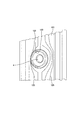
以下、本発明の実施の形態に係る車載用カメラについて、図面を参照しながら説明する。図1は、本発明の実施の形態に係る車載用カメラがフロントバンパーのコーナー部に取り付けられた状態を示す概要図である。なお、本実施の形態で使用する方向は、上下方向とは図1における車載用カメラの上下方向をいうものとし、前側とは図1の左側をいい、後側とは図1の右側をいうものとして説明する。 Hereinafter, an in-vehicle camera according to an embodiment of the present invention will be described with reference to the drawings. FIG. 1 is a schematic view showing a state in which a vehicle-mounted camera according to an embodiment of the present invention is attached to a corner portion of a front bumper. As for the direction used in the present embodiment, the vertical direction means the vertical direction of the in-vehicle camera in FIG. 1, the front side means the left side in FIG. 1, and the rear side means the right side in FIG. It will be explained as a thing.
車載用カメラ1は、図1に示すように、フロントバンパー2に形成された開口に取り付けられたカメラ筐体部(筐体)3と、このカメラ筐体部3に収容されるCCDカメラ(カメラ本体)4と、このCCDカメラ4の前側に配置され、フロントバンパー2の開口から車両外側に臨むレンズカバー5とを備える。
このレンズカバー5は、ホルダ6を介して、当該レンズカバー5を保持するカバー本体7の開口部に嵌め込まれている。このカバー本体7は、カメラ筐体部3の前端部に断熱パッキン8を介してねじ止めされている。
As shown in FIG. 1, the in-
The
カメラ筐体部3は、内部が中空である略筒型に形成され、この内部を前後に仕切る仕切板9を備える。この仕切板9で区分けされたカメラ筐体部3の後方の空間10Aには、CCDカメラ4の制御等を実行するCCD基板11が配置される。また、CCD基板11に接続されるCCDカメラ4は、仕切板9を貫通し、この仕切板9、レンズカバー5及びカバー本体7で形成されたカメラ筐体部3の前方の空間10Bに延在している。
CCDカメラ4は、カメラ筐体部3の略中央部に配置され、レンズカバー5の略中央部の位置に向けられている。また、このCCDカメラ4のレンズカバー5側の先端には、レンズ4aが設けられている。これにより、CCDカメラ4は、レンズ4a及びレンズカバー5を通して、車両外部の情報を撮像できるようになっている。
The
The CCD camera 4 is disposed at a substantially central portion of the
ところで、フロントバンパー2のコーナー部に取り付けられる車載用カメラ1は、カメラ筐体部3がエンジンルーム内に臨むように設置されることになり、車両のエンジンをかけた状態では、外気温とカメラ内部の上記空間10Bの温度との温度差が大きくなる。すなわち、車載用カメラ1の設置場所や、エンジン始動後の経過時間にもよるが、概ね50℃〜80℃の温度差が生じる場合がある。また、車載用カメラ1には、上述した雰囲気温度に加え、車載用カメラ1自体の駆動電力による発熱も加味されることになり、更に空間10Bの温度が上昇する。
ここで、車載用カメラ1の内部に微少な結露水や、吸湿性のある素材(例えば、基板、緩衝材、接着剤等)が存在すると、これらから空間10Bに水蒸気が供給されることになる。そして、水蒸気は、その温度で飽和可能な状態まで蒸発し、空間10Bを漂うことになる。
By the way, the vehicle-mounted
Here, if there is a minute amount of condensed water or a hygroscopic material (for example, a substrate, a buffer material, an adhesive, etc.) inside the in-
一方、外気と直接接するレンズカバー5は、光の透過性は高いが熱伝導率の低い物質で構成されている。外気は、レンズカバー5と接する全面に対して、レンズカバー5の厚み方向に一様に冷気を伝達する。しかし、カバー本体7を介して、車両(フロントバンパー)に接する(取り付けられる)レンズカバー5の外周縁部には、車両及びエンジンルーム内の熱が伝導されるので、この外周縁部は比較的高い温度に維持される。これに対し、レンズカバー5の中央部付近では、レンズカバー5の熱伝導率が低いことに起因して車両及びエンジンルーム内の熱が伝導され難く、外気の影響を受けて低い温度となる。そのため、レンズカバー5の内面、特にレンズカバー5の中央部付近では、空間10Bを漂う水蒸気が結露水として付着する。
On the other hand, the
このため、本実施形態では、車載用カメラ1のレンズカバー5の内面に結露や曇りの発生を防止すべく様々な工夫がなされている。次に、結露及び曇りを防止するための構成について説明する。
上記したカメラ筐体部3の前方の空間10Bには、図1に示すように、レンズカバー5の内側に、このレンズカバー5と同等の温度に維持される結露板21(結露部)が配置されている。この結露板21は、空間10Bを漂う水蒸気を当該結露板21にて積極的に結露させることにより、相対的にレンズカバー5での結露の発生を抑制するものである。
For this reason, in this embodiment, various devices have been made to prevent the occurrence of condensation and fogging on the inner surface of the
As shown in FIG. 1, a condensing plate 21 (condensation part) that is maintained at a temperature equivalent to that of the
結露板21は、レンズカバー5よりも熱伝導率の高い金属で構成されており、図2に示すように、結露板本体21Aと、この結露板本体21Aの下端に斜面部を介して設けられた水平部21Bと、この水平部21Bの先端に連結された放熱部(一部)21Cとを備える。この放熱部21Cは、図1に示すように、レンズカバー5とカバー本体7との間を通じて、レンズカバー5の外側に延在している。このため、放熱部21Cは、常時、外気に晒されて冷却されることにより、結露板本体21Aをカメラ筐体部3よりも数段低い温度に維持することができる。
また、結露板本体21Aと仕切板9との間には遮熱板22が介装されている。この遮熱板22は、結露板本体21Aをカメラ筐体部3から熱的に遮断し、このカメラ筐体部3からの輻射熱により結露板本体21Aが温められるのを防止する。
The
Further, a
また、結露板本体21Aには、この結露板本体21Aの上縁から略中央部まで延びる切り欠き21部Dが形成され、この切り欠き部21DにCCDカメラ4が配置されている。このため、本構成では、CCDカメラ4の上方に位置する結露板本体21Aが切り欠かれているため、この結露板本体21Aで結露した水がCCDカメラ4に付着することが防止される。
The
一般的に、結露は平坦面よりも、突起、傷、汚れなどの平坦ではない、言い換えれば不連続部分を基点として成長する傾向にある。本実施形態では、レンズカバー5に対向する結露板本体21Aの面の一部に、エッチング加工もしくは凹凸加工等の不連続部分を形成する加工(不図示)が施されている。これによれば、結露板本体21Aの特定場所、例えば、CCDカメラ4もしくはCCD基板11から離れた場所に、結露を生じさせ易くすることができ、これらCCDカメラ4、CCD基板11に対する結露の影響を極力低減することができる。
In general, dew condensation is less flat than a flat surface, such as protrusions, scratches, and dirt, in other words, tends to grow from a discontinuous portion as a base point. In the present embodiment, a process (not shown) for forming a discontinuous portion such as an etching process or a concavo-convex process is performed on a part of the surface of the condensation plate
次に、図3を参照して結露板21の作用について説明する。
上述したように、車載用カメラ1における主な熱源は、図3の右方向に位置するカメラ1の駆動電源と外部のエンジンルームからの輻射熱である。これらの熱源によって暖められた空間10A内の空気は、熱膨張するとともに、この空間10A内で対流し、例えば、CCDカメラ4と仕切板9の貫通孔との隙間を通じて空間10Bに流入する。
この時、従来の構成であれば、レンズカバー5に接した段階で、空気中に含まれる水蒸気が冷却され、このレンズカバー5上に微小な水滴を生じる。しかしながら、本実施形態では、レンズカバー5と仕切板9との間に結露板21を配置しているため、この結露板21の結露板本体21Aで空気が露点以下に冷却される。これによれば、空気中に含まれる水蒸気25は、結露板本体21Aの表面で結露して水滴26を生じるため、空間10B内の空気に含まれる水蒸気量は大幅に減少する事になる。
従って、この空気がレンズカバー5の内面に至ったとしても、この空気は結露板本体21A上で既に飽和水蒸気量に達しているため、レンズカバー5での結露はほとんど無く、結果として車載用カメラ1の視界を良好に保持することができる。なお、結露板本体21Aに生じた水滴26は、この結露板本体21Aを流下して、水平部21B(貯留部)に貯留される。このため、結露した水が空間10A内に流入することはなく、CCD基板11への悪影響を低減することができる。
Next, the operation of the
As described above, the main heat source in the in-
At this time, if it is a conventional configuration, the water vapor contained in the air is cooled at the stage of contact with the
Therefore, even if this air reaches the inner surface of the
結露板21は、結露に対する即応性が高いため、結露対策として有効である一方、空間10B内に含まれる水蒸気量を減少することはできない。このため、本実施形態では、結露板21に加えて、空間10B内の水蒸気を外部に発散させることにより、車載用カメラ1内の水蒸気の総量を調整可能な構成を備える。
具体的には、図1に示すように、カバー本体7の下部には、このカバー本体7とカメラ筐体部3の底面との間に、レンズカバー5の内側の空間10Bと、このレンズカバー5の外側の空間30(すなわち外気)とを連通する連通路31が形成され、この連通路31には、水分を遮断しつつ湿気のみを通す透湿性防水素材32が配置されている。この透湿性防水素材32は、孔径が0.3〜10μm程度に形成された多孔質素材であり、100μm程度の大きさを有する水滴の浸入を阻止するとともに、0.0004μm程度の大きさを有する水蒸気を通すという特性を有する。
これによれば、水滴や塵埃の進入を阻止しつつも、透湿性防水素材32を通じて水蒸気を外側の空間30に排出することができ、空間10B内の水蒸気の総量を低減することができる。
Since the
Specifically, as shown in FIG. 1, a space 10 </ b> B inside the
According to this, water vapor can be discharged to the
上述のように、連通路31に透湿性防水素材32を配置することにより、この透湿性防水素材32が空間10B内への水滴や塵埃の進入を防止している。しかし、カメラ内部は精密な電子機器(CCDカメラ4及びCCD基板11)の集合体であるため、連通路31を通じて空間10B内の水蒸気を排出する時以外は、カメラ筐体部3の気密性を確保することが望ましい。
このため、本実施形態では、車載用カメラ1は、カメラ筐体部3の温度に応じて、上記連通路31を開閉するシャッタ機構33(開閉機構)を備える。このシャッタ機構33は、図4に示すように、それぞれスリット状に形成された複数の開口34A、35Aを有する第1シャッタ部34及び第2シャッタ部35を備え、これら第1シャッタ部34及び第2シャッタ部35を重ね合わせて構成されている。
本実施形態では、第1シャッタ部34はカメラ筐体部3の下面に一体に形成され、第2シャッタ部35は、カバー本体7の下面に一体に形成されているが、それぞれカメラ筐体部3、カバー本体7と別部材で形成して連結する構成としても良い。
As described above, by disposing the moisture-permeable
For this reason, in the present embodiment, the in-
In the present embodiment, the
第1シャッタ部34は、温度変化による熱膨張率が大きい素材で形成され、第2シャッタ部35は、断熱性に優れ熱膨張率が比較的少ない素材で形成されている。シャッタ機構33は、第1シャッタ部34及び第2シャッタ部35の熱膨張率の差を利用して開閉するものである。具体的には、カメラ筐体部3の温度が低温(例えば、30℃程度)の場合には、第1シャッタ部34及び第2シャッタ部35は、それぞれの開口34A、35Aを閉じ、カメラ筐体部3の温度が高温(例えば、50℃程度)の場合には、それぞれの開口34A、35Aを開いて空間10B内の水蒸気を排出する。
The
また、本実施形態では、カメラ筐体部3の底面には、図4に示すように、透湿性防水素材32に隣接して結露板21で結露した結露水の一部を受ける受け部36が形成されている。この受け部36は、カメラ筐体部3の熱が伝えられ、この受け部36で受けた水を再度蒸発させる蒸発皿として機能するものである。
Further, in the present embodiment, on the bottom surface of the
次に、図4及び図5を参照して透湿性防水素材32及びシャッタ機構33の作用について説明する。
車両のエンジンが停止している場合など、カメラ筐体部3の温度が低温(例えば、30℃程度)の場合には、図4に示すように、第1シャッタ部34の開口34Aと第2シャッタ部35の開口35Aとがずれて配置されることにより、カメラ筐体部3の気密性が確保される。この場合、空間10B内の水蒸気は透湿性防水素材32を通過しても、シャッタ機構33が開放されていないため、外側の空間30に排出されることはない。しかしながら、カメラ筐体部3の温度が低温のときには結露の問題自体が発生しないので、シャッタ機構33を開放しなくても問題が生じるおそれは低い。
一方、エンジン始動時など、カメラ筐体部3の温度が高温(例えば、50℃程度)の場合には、図5に示すように、第1シャッタ部34が熱膨張して、前方(図中X方向)に延び、第1シャッタ部34の開口34Aと第2シャッタ部35の開口35Aとが重なる。これにより、空間10B内の水蒸気25は透湿性防水素材32を通過するともに、上記開口34A、35Aを通過して、外側の空間30に排出される。
また、上記結露板21で結露した結露水の一部は、結露板21の下方に位置する蒸発皿としての受け部36上に貯留される。この受け部36は、カメラ筐体部3上に形成されているため、このカメラ筐体部3の温度によって、当該受け部36に溜まった水を再度蒸発することができる。そして、この再度蒸発した水蒸気も透湿性防水素材32及び上記開口34A、35Aを通過して、外側の空間30に排出される。
これによれば、空間10B内の空気に含まれる水蒸気の総量を低減することができるため、レンズカバー5での結露の発生を抑制することができる。
Next, operations of the moisture-permeable
When the temperature of the
On the other hand, when the temperature of the
A part of the condensed water condensed on the
According to this, since the total amount of water vapor contained in the air in the
レンズカバー5の内面に結露が生じた場合には、この結露水によって光が散乱することにより、カメラの視界が悪化する。上記した結露板21や透湿性防水素材32は、レンズカバー5の内面への結露を抑制するものであるが、このレンズカバー5に結露水が付着した場合には、カメラの良好な視界を確保することが困難となる。
このため、本実施形態では、結露板21及び透湿性防水素材32に加えて、レンズカバー5の内面に結露水が付着した場合であっても、この結露水による光の散乱を防止する構成を備えている。
When dew condensation occurs on the inner surface of the
For this reason, in this embodiment, in addition to the
具体的には、図1に示すように、レンズカバー5の内側には親水性膜41が形成されている。親水性膜41は、この親水性膜41に付着した微小な水滴を球形から膜状に変化させることにより、光の散乱を防止するものである。
親水性膜41は、例えば、PVA(ポリビニルアルコール)や塩酸ポリアリルアミン酸等に代表される高分子系材料で形成されているため、レンズカバー5の内側に親水性膜41を簡単に形成することができる。また、親水性膜41は、無色透明であるため、この親水性膜41を形成することによって、レンズカバー5の視界が悪化することはない。
Specifically, as shown in FIG. 1, a
The
次に、図6を参照して親水性膜41の作用について説明する。
空間10B内の空気に含まれる水蒸気25は、レンズカバー5により冷却されて球状の水滴26となる。この水滴26は、当初はレンズカバー5の内面に形成された親水性膜41の内部に取り込まれ親和状態となる。そして、結露が進行すると、水滴26は親水性膜41上に広がり、略一定の厚みを有する水膜27が形成される。
このため、レンズカバー5の内面に結露水が付着した場合であっても、この結露水を親水性膜41が水膜27として保持するため、光学的な散乱現象が発生せず、結露で問題となるカメラ映像の視界悪化を防ぐことができる。
Next, the operation of the
The
For this reason, even when condensed water adheres to the inner surface of the
ところで、車載用カメラ1は、カメラ筐体部3内に外部から水分が浸入しない程度の気密性を備えて構成されている。しかし、どれほど高い気密性を備えようとも、経年変化により、カメラ筐体部3内に多少の水分が浸入することは否めない。この水分がカメラの電子機器(CCD基板11等)へ浸入すると故障の原因となるため、速やかな処置が必要となる。この場合、根本的な処置としては、車載用カメラ1を分解して内部に浸入した水分を取り除いて、再度、気密防水処理を行う事が望ましい。
しかし、レンズカバー5を通して目視できるほど多量の水分が存在しているならばともかく、本実施形態では、上述のように、結露を防止する様々な構成を有することにより、レンズカバー5に結露が生じにくくなっているため、ユーザが分解修理の必要性を認識できない。
そこで、本実施形態では、カメラ筐体部3内に水分が浸入した場合に、その旨をユーザに報知する構成を備えている。
By the way, the vehicle-mounted
However, regardless of the presence of a large amount of moisture that can be visually observed through the
Therefore, in the present embodiment, when moisture enters the
上述のように、結露板21の結露板本体21Aに生じた水滴26は、この結露板本体21Aを流下して、貯留部として機能する結露板21の水平部21Bに貯留される。また、レンズカバー5の内側に形成された親水性膜41に多量の結露水が生じると、この結露水は親水性膜41上に水膜27として広がるが、この水膜27は重力の影響からレンズカバー5の下部に配置された結露板21の水平部21Bに貯留される。
水平部21Bには、図1に示すように、この水平部21Bに水が貯留されると、この水に濡れて発色する発色表示板(報知手段)42が配置されている。
As described above, the
As shown in FIG. 1, the
発色表示板42は、不織布のような含水性を有する素材に水発色インキを含ませたものであり、水に濡れると例えば赤色に発色するようになっている。この発色表示板42は、水平部21B上、すなわち、レンズカバー5を通じて目視可能な位置に配置されているため、この発色表示板42が水に濡れて発色した場合には、ユーザは車載用カメラ1内に水分が浸入していることを視覚を通じて認識することができる。これによれば、車載用カメラ1を分解して内部に浸入した水分を取り除くことができるため、この浸入した水分によって車載用カメラ1が故障することを防止することができる。
なお、発色表示板42は、水平部21Bに貯留された水量に応じて発色させる範囲を変化させても良い。具体的には、図7に示すように、発色表示板42を、縁部R1と中央部R2とに区分けし、これら縁部R1及び中央部R2に異なる水発色インキを含ませる。これによれば、貯留された水が少なければ縁部R1のみが発色し、この貯留された水量が多くなれば中央部R2まで濡れて、この中央部R2が発色するため、ユーザは、車載用カメラ1内に浸入した水量についても視覚を通じて認識することが可能となる。
The
Note that the
以上、説明したように、本実施形態によれば、CCDカメラ4を収容するカメラ筐体部3と、このCCDカメラ4の前面側に配置されるレンズカバー5とを備え、このレンズカバー5の内側に、当該レンズカバー5よりも熱伝導性の高い材質で形成された結露板21を配置するとともに、この結露板21の一部である放熱部21Cをレンズカバー5の外側に延在させたため、この放熱部21Cは、常時、外気に晒されて冷却されることにより、結露板本体21Aをカメラ筐体部3よりも数段低い温度に維持することができる。このため、この結露板本体21Aで空気が露点以下に冷却されることにより、空気中に含まれる水蒸気25は、結露板本体21Aの表面で結露して水滴26を生じるため、空間10B内の空気に含まれる水蒸気量は大幅に減少する事になる。従って、この空気がレンズカバー5の内面に至ったとしても、この空気は結露板本体21A上で既に飽和水蒸気量に達しているため、レンズカバー5での結露及び曇りはほとんど無く、結果として車載用カメラ1の視界を良好に保持することができる。
さらに、ヒータ、温度センサ及び送風機などを使用することなく、結露対策が可能となるため、車載用カメラ1の製造コストを低減させることができる。さらに、車載用カメラ1を強固な気密構造にする必要がなく、生活防水程度の防水構造で十分であるため、安価に車載用カメラ1を製作することができる。さらに、乾燥剤等を車載用カメラ1の内部に設ける必要がなく、製造コストを低減させることができる。
As described above, according to the present embodiment, the
Furthermore, since it is possible to take measures against condensation without using a heater, a temperature sensor, a blower, or the like, the manufacturing cost of the in-
また、本実施形態によれば、結露板21の結露板本体21Aとカメラ筐体部3の仕切板9との間に、このカメラ筐体部3から発せられる輻射熱を遮断する遮熱板22を配置したため、この輻射熱によって結露板本体21Aが温められるのを防止されることにより、この結露板本体21Aでの結露を促進することができる。
Further, according to the present embodiment, the
また、本実施形態によれば、レンズカバー5に対向する結露板本体21Aの面の一部に、エッチング加工もしくは凹凸加工等の不連続部分を形成する加工が施されているため、結露板本体21Aの特定場所、例えば、CCDカメラ4もしくはCCD基板11から離れた場所に、結露を生じさせ易くすることができ、これらCCDカメラ4、CCD基板11に対する結露の影響を極力低減することができる。
In addition, according to the present embodiment, a part of the surface of the dew plate
また、本実施形態によれば、CCDカメラ4を収容するカメラ筐体部3と、このCCDカメラ4の前面側に配置されるレンズカバー5とを備えるとともに、このレンズカバー5とCCDカメラ4との空間10Bと、当該レンズカバー5の外側の空間30とを連通する連通路31を備え、この連通路31に外気の水分を遮断し且つ湿気のみを通す透湿性防水素材32を配置したため、この透湿性防水素材32を介して空間10Bの水蒸気が外側の空間30に排出されるため、上記空間10B内の湿度が低下し、レンズカバー5での結露が防止される。このため、レンズカバー5の内側の結露及び曇りが防止されることにより、車載用カメラ1の視界を良好に保持できる。
さらに、ヒータ、温度センサ及び送風機などを使用することなく、結露対策が可能となるため、車載用カメラ1の製造コストを低減させることができる。さらに、車載用カメラ1を強固な気密構造にする必要がなく、生活防水程度の防水構造で十分であるため、安価に車載用カメラ1を製作することができる。さらに、乾燥剤等を車載用カメラ1の内部に設ける必要がなく、製造コストを低減させることができる。
In addition, according to the present embodiment, the
Furthermore, since it is possible to take measures against condensation without using a heater, a temperature sensor, a blower, or the like, the manufacturing cost of the in-
また、本実施形態によれば、連通路31には、この連通路31を開閉するシャッタ機構33を設けたため、この連通路31を通じて空間10B内の水蒸気を排出する時以外は、シャッタ機構33を閉鎖することにより、カメラ筐体部3の気密性を確保することができる。
Further, according to the present embodiment, since the
また、本実施形態によれば、シャッタ機構33は、カメラ筐体部3に連結される第1シャッタ部34と、この第1シャッタ部34に重ねて配置される第2シャッタ部35とを備え、これら第1シャッタ部34及び第2シャッタ部35の熱膨張率の差に基づいて当該シャッタ機構33を開閉するため、このシャッタ機構33を開閉するためのアクチュエータを設ける必要がなく、当該シャッタ機構33の簡素化を図るとともに、車載用カメラ1の小型化を図ることができる。
Further, according to the present embodiment, the
また、本実施形態によれば、シャッタ機構33は、車両のエンジンの輻射熱に応じて開閉するため、このシャッタ機構33を開閉するために特別な熱源を使用することがない。すなわち、結露の原因となる温度差(廃熱)を利用して、シャッタ機構33の開閉を行うため、熱源供給の心配がない。熱源が供給されない場合、つまり、エンジンが低温のときには結露水の問題自体が発生しないので、このシャッタ機構33を開く必要がない。すなわち、シャッタ機構33を自動的に、必要なときにだけ動作させることができる。
In addition, according to the present embodiment, the
また、本実施形態によれば、CCDカメラ4を収容するカメラ筐体部3と、このCCDカメラ4の前面側に配置されるレンズカバー5とを備え、このレンズカバー5の内側に親水性膜41を形成したため、レンズカバー5の内側に結露した水滴が付着したとしても、この水滴は親水性膜41に取り込まれる、もしくは、この親水性膜41上に水膜27として広げられるため、この水滴に起因する光の散乱が防止される、このため、レンズカバー5の内側の曇りが防止されることにより、車載用カメラ1の視界を良好に保持できる。
さらに、ヒータ、温度センサ及び送風機などを使用することなく、結露対策が可能となるため、車載用カメラ1の製造コストを低減させることができる。さらに、車載用カメラ1を強固な気密構造にする必要がなく、生活防水程度の防水構造で十分であるため、安価に車載用カメラ1を製作することができる。さらに、乾燥剤等を車載用カメラ1の内部に設ける必要がなく、製造コストを低減させることができる。
In addition, according to the present embodiment, the
Furthermore, since it is possible to take measures against condensation without using a heater, a temperature sensor, a blower, or the like, the manufacturing cost of the in-
また、本実施形態によれば、親水性膜41は、高分子系材料で形成されているため、レンズカバー5の内側に親水性膜41を簡単に形成することができる。また、親水性膜41は、無色透明であるため、この親水性膜41を形成することによって、レンズカバー5の視界が悪化することはない。
Moreover, according to this embodiment, since the hydrophilic film |
また、本実施形態によれば、カメラ筐体部3の内部を前後に仕切る仕切板9を設け、この仕切板9とレンズカバー5との間に、当該レンズカバー5を流下した結露水を貯留可能な結露板21の水平部21Bを設けたため、この水がCCD基板11等の電装部品を収容した空間10A内に流入することはなく、この水によって車載用カメラ1が故障することを防止できる。
Further, according to the present embodiment, the
また、本実施形態によれば、結露板21の水平部21Bに結露水が貯留されると、この水に濡れて発色する発色表示板42を、レンズカバー5を通じて目視可能な水平部21B上に配置したため、ユーザは車載用カメラ1内に水分が浸入していることを視覚を通じて認識することができる。これによれば、車載用カメラ1を分解して内部に浸入した水分を取り除くことができるため、この浸入した水分によって車載用カメラ1が故障することを防止できる。
Further, according to the present embodiment, when condensed water is stored in the
以上、本発明を実施するための最良の形態について述べたが、本発明は既述の実施形態に限定されるものではなく、本発明の技術思想に基づいて各種の変形および変更が可能である。例えば、本実施形態では、結露板21は、一枚の板部材を屈曲させて形成しているが、結露板本体21Aと放熱部21Cとが熱的に連結されていれば、どのように構成しても構わない。
また、本実施形態では、シャッタ機構33は、第1シャッタ部34及び第2シャッタ部35の熱膨張率の差を利用して開閉するものとしていたが、空間10B内の温度を検知して、この結果に応じて、例えばシリンダを用いて機械的に開閉する機構としても良い。
また、本実施形態では、報知手段として、結露板21の水平部21Bに結露水が貯留された場合に、この水に濡れて発色する発色表示板42が配置されているものとしたが、結露水の有無をセンサによって検知し、この結果をランプやブザーで報知する構成としても良い。
The best mode for carrying out the present invention has been described above. However, the present invention is not limited to the above-described embodiment, and various modifications and changes can be made based on the technical idea of the present invention. . For example, in the present embodiment, the
In the present embodiment, the
Further, in the present embodiment, as the notification means, the
また、本実施形態では、結露板21の結露板本体21Aは、CCDカメラ4が配置される部分を切り欠いた1枚の金属プレートであるが、これに限るものではなく、図8に示すように、結露板121は、CCDカメラ4が貫通する貫通孔部122を備え、この貫通孔部122の縁部に返し部123を設けた構成としても良い。この構成によれば、結露板を流下した結露水は、貫通孔部122の縁部に形成された返し部123によって、この貫通孔部122内に浸入することが防止されるため、CCDカメラ4に結露水が付着することが防止される。
さらに、カメラは使用する場合の上下方向が決まっている事が多いため、結露板121に波型状の流路溝125形成し、この流路溝125に沿った流れに方向性を与え、結露した水滴の排水を促す構造としても良い。
In the present embodiment, the
Further, since the camera is often used in a vertical direction when it is used, a corrugated
1 車載用カメラ
2 フロントバンパー
3 カメラ筐体部(筐体)
4 CCDカメラ(カメラ本体)
5 レンズカバー
7 カバー体
10B 空間
21、121 結露板(結露部)
21A 結露板本体
21B 水平部(貯留部)
21C 放熱部(一部)
22 遮熱板
31 連通路
32 透湿性防水素材
33 シャッタ機構(開閉機構)
34 第1シャッタ部
34A、35A 開口
35 第2シャッタ部
41 親水性膜
42 発色表示板(報知手段)
122 貫通孔部
123 返し部
1 In-
4 CCD camera (camera body)
5
21A
21C Heat dissipation part (part)
22
34
122 Through-
Claims (4)
カメラ本体を収容する筐体と、このカメラ本体の前面側に配置されるレンズカバーとを備え、このレンズカバーの内側に、当該レンズカバーよりも熱伝導性の高い材質で形成された結露部を配置するとともに、この結露部の一部を前記レンズカバーの外側に延在させたことを特徴とする車載用カメラ。 In an in-vehicle camera that images the surroundings of a vehicle
A housing for housing the camera body and a lens cover disposed on the front side of the camera body, and a dew condensation part formed of a material having higher thermal conductivity than the lens cover inside the lens cover. An in-vehicle camera characterized in that it is disposed and a part of the dew condensation portion extends outside the lens cover.
Priority Applications (1)
| Application Number | Priority Date | Filing Date | Title |
|---|---|---|---|
| JP2007084100A JP2008242187A (en) | 2007-03-28 | 2007-03-28 | Onboard camera |
Applications Claiming Priority (1)
| Application Number | Priority Date | Filing Date | Title |
|---|---|---|---|
| JP2007084100A JP2008242187A (en) | 2007-03-28 | 2007-03-28 | Onboard camera |
Publications (2)
| Publication Number | Publication Date |
|---|---|
| JP2008242187A true JP2008242187A (en) | 2008-10-09 |
| JP2008242187A5 JP2008242187A5 (en) | 2010-05-06 |
Family
ID=39913612
Family Applications (1)
| Application Number | Title | Priority Date | Filing Date |
|---|---|---|---|
| JP2007084100A Pending JP2008242187A (en) | 2007-03-28 | 2007-03-28 | Onboard camera |
Country Status (1)
| Country | Link |
|---|---|
| JP (1) | JP2008242187A (en) |
Cited By (12)
| Publication number | Priority date | Publication date | Assignee | Title |
|---|---|---|---|---|
| CN102162980A (en) * | 2010-12-21 | 2011-08-24 | 天津市亚安科技电子有限公司 | Window glass dew prevention system for camera housing |
| JP2011240912A (en) * | 2009-09-29 | 2011-12-01 | Denso Corp | On-board optical sensor cover |
| JP2012028974A (en) * | 2010-07-22 | 2012-02-09 | Japan Aviation Electronics Industry Ltd | Dew condensation prevention mechanism |
| JP2013211697A (en) * | 2012-03-30 | 2013-10-10 | Fujifilm Corp | Imaging apparatus, electronic endoscope apparatus, and dew condensation removing method thereof |
| US8970700B2 (en) | 2010-06-07 | 2015-03-03 | Ricoh Company, Ltd. | Imaging apparatus |
| JP2015169816A (en) * | 2014-03-07 | 2015-09-28 | 船井電機株式会社 | Dew condensation prevention structure of optical component and head up display device |
| JP2016205825A (en) * | 2015-04-15 | 2016-12-08 | コニカミノルタ株式会社 | Optical scanning object detection device |
| KR20170014341A (en) * | 2015-07-29 | 2017-02-08 | 엘지이노텍 주식회사 | Camera Module |
| CN108337423A (en) * | 2018-05-15 | 2018-07-27 | 深圳集栈科技有限公司 | Antifog photographic device and vending equipment based on chip heat transfer |
| JP2018153375A (en) * | 2017-03-17 | 2018-10-04 | 日立アプライアンス株式会社 | Electric apparatus, autonomous traveling vacuum cleaner as electric apparatus and system including electric apparatus and base |
| WO2020028733A1 (en) * | 2018-08-03 | 2020-02-06 | Molex, Llc | Sense unit assembly having an embedded heating element and method of forming same |
| CN116149116A (en) * | 2023-04-18 | 2023-05-23 | 江西联创电子有限公司 | Lens structure, camera module and electronic equipment |
Citations (9)
| Publication number | Priority date | Publication date | Assignee | Title |
|---|---|---|---|---|
| JPS5388818A (en) * | 1977-01-17 | 1978-08-04 | Minolta Camera Kk | Hazeeproof device for transparent window in waterrproof case |
| JPS6210491U (en) * | 1985-07-03 | 1987-01-22 | ||
| JPH07159874A (en) * | 1993-12-03 | 1995-06-23 | Nikon Corp | Underwater camera |
| JP2000194048A (en) * | 1998-12-25 | 2000-07-14 | Fuji Photo Film Co Ltd | Waterproof camera |
| JP2001133876A (en) * | 1999-11-01 | 2001-05-18 | Fuji Photo Film Co Ltd | Image pickup device |
| JP2002350966A (en) * | 2001-05-25 | 2002-12-04 | Hitachi Building Systems Co Ltd | Burglar prevention camera |
| JP2005117258A (en) * | 2003-10-06 | 2005-04-28 | Olympus Corp | Imaging device |
| JP2005250306A (en) * | 2004-03-08 | 2005-09-15 | Canon Inc | Television camera housing |
| JP2006313312A (en) * | 2005-04-08 | 2006-11-16 | Murakami Corp | Optical apparatus, anti-fogging device and anti-fogging mirror unit |
-
2007
- 2007-03-28 JP JP2007084100A patent/JP2008242187A/en active Pending
Patent Citations (9)
| Publication number | Priority date | Publication date | Assignee | Title |
|---|---|---|---|---|
| JPS5388818A (en) * | 1977-01-17 | 1978-08-04 | Minolta Camera Kk | Hazeeproof device for transparent window in waterrproof case |
| JPS6210491U (en) * | 1985-07-03 | 1987-01-22 | ||
| JPH07159874A (en) * | 1993-12-03 | 1995-06-23 | Nikon Corp | Underwater camera |
| JP2000194048A (en) * | 1998-12-25 | 2000-07-14 | Fuji Photo Film Co Ltd | Waterproof camera |
| JP2001133876A (en) * | 1999-11-01 | 2001-05-18 | Fuji Photo Film Co Ltd | Image pickup device |
| JP2002350966A (en) * | 2001-05-25 | 2002-12-04 | Hitachi Building Systems Co Ltd | Burglar prevention camera |
| JP2005117258A (en) * | 2003-10-06 | 2005-04-28 | Olympus Corp | Imaging device |
| JP2005250306A (en) * | 2004-03-08 | 2005-09-15 | Canon Inc | Television camera housing |
| JP2006313312A (en) * | 2005-04-08 | 2006-11-16 | Murakami Corp | Optical apparatus, anti-fogging device and anti-fogging mirror unit |
Cited By (13)
| Publication number | Priority date | Publication date | Assignee | Title |
|---|---|---|---|---|
| JP2011240912A (en) * | 2009-09-29 | 2011-12-01 | Denso Corp | On-board optical sensor cover |
| US8970700B2 (en) | 2010-06-07 | 2015-03-03 | Ricoh Company, Ltd. | Imaging apparatus |
| JP2012028974A (en) * | 2010-07-22 | 2012-02-09 | Japan Aviation Electronics Industry Ltd | Dew condensation prevention mechanism |
| CN102162980A (en) * | 2010-12-21 | 2011-08-24 | 天津市亚安科技电子有限公司 | Window glass dew prevention system for camera housing |
| JP2013211697A (en) * | 2012-03-30 | 2013-10-10 | Fujifilm Corp | Imaging apparatus, electronic endoscope apparatus, and dew condensation removing method thereof |
| JP2015169816A (en) * | 2014-03-07 | 2015-09-28 | 船井電機株式会社 | Dew condensation prevention structure of optical component and head up display device |
| JP2016205825A (en) * | 2015-04-15 | 2016-12-08 | コニカミノルタ株式会社 | Optical scanning object detection device |
| KR20170014341A (en) * | 2015-07-29 | 2017-02-08 | 엘지이노텍 주식회사 | Camera Module |
| KR102422324B1 (en) * | 2015-07-29 | 2022-07-18 | 엘지이노텍 주식회사 | Camera Module |
| JP2018153375A (en) * | 2017-03-17 | 2018-10-04 | 日立アプライアンス株式会社 | Electric apparatus, autonomous traveling vacuum cleaner as electric apparatus and system including electric apparatus and base |
| CN108337423A (en) * | 2018-05-15 | 2018-07-27 | 深圳集栈科技有限公司 | Antifog photographic device and vending equipment based on chip heat transfer |
| WO2020028733A1 (en) * | 2018-08-03 | 2020-02-06 | Molex, Llc | Sense unit assembly having an embedded heating element and method of forming same |
| CN116149116A (en) * | 2023-04-18 | 2023-05-23 | 江西联创电子有限公司 | Lens structure, camera module and electronic equipment |
Similar Documents
| Publication | Publication Date | Title |
|---|---|---|
| JP2008242187A (en) | Onboard camera | |
| JP5006080B2 (en) | In-vehicle camera | |
| JP6304205B2 (en) | In-vehicle imaging device | |
| CN105812628B (en) | Camera module for vehicle | |
| JP2009021245A (en) | Dehumidification device of headlight for automobile and headlight system equipped with this device | |
| US8300203B2 (en) | Display apparatus | |
| JP2008242187A5 (en) | ||
| US20040032668A1 (en) | Camera arrangement for motor vehicles | |
| JP2008239018A (en) | On-vehicle camera | |
| RU2673790C1 (en) | Optical system designed for a vehicle | |
| KR20130124355A (en) | Pressure equalizing element, battery having a pressure equalizing element, and motor vehicle having a corresponding battery | |
| JP5132908B2 (en) | In-vehicle camera | |
| JP2007069771A (en) | Head-up display device for vehicle | |
| KR20140134467A (en) | CCTV camera housing with multi heater | |
| JP2006350187A (en) | Camera device | |
| JP4597067B2 (en) | Vehicle lamp | |
| JP2001088610A (en) | Vehicle light with built-in camera | |
| US10870399B2 (en) | Sensor arrangement for a motor vehicle, motor vehicle and method for operating a sensor device | |
| JP2003050219A (en) | Anti-fogging property evaluation device | |
| CN107678078A (en) | The manufacture method of camera device, lens cap and lens cap | |
| US20230023735A1 (en) | Camera assembly with cooled internal illuminator | |
| KR101969054B1 (en) | Dehumidification device for security cameras and security camera for moisture protection | |
| JP2010134198A (en) | Image display apparatus | |
| JP2004258293A (en) | Camera with stabilizer | |
| JP2016199150A (en) | Desiccant apparatus for vehicle |
Legal Events
| Date | Code | Title | Description |
|---|---|---|---|
| A521 | Request for written amendment filed |
Free format text: JAPANESE INTERMEDIATE CODE: A523 Effective date: 20100323 |
|
| A621 | Written request for application examination |
Free format text: JAPANESE INTERMEDIATE CODE: A621 Effective date: 20100323 |
|
| RD02 | Notification of acceptance of power of attorney |
Free format text: JAPANESE INTERMEDIATE CODE: A7422 Effective date: 20100323 |
|
| A131 | Notification of reasons for refusal |
Free format text: JAPANESE INTERMEDIATE CODE: A131 Effective date: 20120214 |
|
| A977 | Report on retrieval |
Free format text: JAPANESE INTERMEDIATE CODE: A971007 Effective date: 20120215 |
|
| A02 | Decision of refusal |
Free format text: JAPANESE INTERMEDIATE CODE: A02 Effective date: 20120703 |