JP2008218386A - Light emitting device - Google Patents
Light emitting device Download PDFInfo
- Publication number
- JP2008218386A JP2008218386A JP2007221191A JP2007221191A JP2008218386A JP 2008218386 A JP2008218386 A JP 2008218386A JP 2007221191 A JP2007221191 A JP 2007221191A JP 2007221191 A JP2007221191 A JP 2007221191A JP 2008218386 A JP2008218386 A JP 2008218386A
- Authority
- JP
- Japan
- Prior art keywords
- heat
- light source
- housing
- optical axis
- emitting device
- Prior art date
- Legal status (The legal status is an assumption and is not a legal conclusion. Google has not performed a legal analysis and makes no representation as to the accuracy of the status listed.)
- Withdrawn
Links
Images


Abstract
Description
本発明は発光装置に関する。詳しくは、発光装置の放熱機構の改良に関する。 The present invention relates to a light emitting device. In detail, it is related with the improvement of the thermal radiation mechanism of a light-emitting device.
室内照明器具、車両の灯具など様々な用途に発光装置が使用されているが、光量の大きな照明器具や灯具に使用される発光装置では、熱対策が重要である。熱対策の一つとして、ヒートパイプを利用したものがある。例えば、特許文献1には、入熱部がハウジング内の光源へ取り付けられ、排熱部がハウジング外のヒートシンクに取り付けられるヒートパイプを備えた発光装置が開示されている。この発光装置では、光源で発生する熱をヒートパイプによりハウジング外に放出する。また、特許文献2には、ループ状のヒートパイプを利用して光源の熱をハウジング外部に放出する発光装置が開示されている。
Light emitting devices are used in various applications such as indoor lighting fixtures and vehicle lamps, but heat countermeasures are important in light emitting devices used in lighting fixtures and lighting fixtures with a large amount of light. One countermeasure against heat is the use of heat pipes. For example,
車両のヘッドライトや室内ダウンライトなどの発光装置では光軸を角度調整する必要がある。これらの発光装置における熱対策として、上記文献に開示されるヒートパイプを採用すれば、各部材の位置が固定されているため、光軸の角度調整を行うには装置全体の設置角度を変更しなければならない。このような設置角度の変更は煩雑な作業を伴う。また、一旦組み付けた後に光軸の角度調整を行うことは困難である。このように、従来の熱対策は光軸の角度調整を考慮した構成となっていない。
そこで、本発明は、放熱性に優れ、かつ光軸の角度調整が容易な発光装置を提供することを目的とする。
In a light emitting device such as a vehicle headlight or indoor downlight, the angle of the optical axis needs to be adjusted. As heat countermeasures in these light emitting devices, if the heat pipe disclosed in the above document is adopted, the position of each member is fixed, so the angle of the optical axis can be adjusted by changing the installation angle of the entire device. There must be. Such a change in the installation angle is complicated. In addition, it is difficult to adjust the angle of the optical axis after being assembled once. As described above, the conventional heat countermeasure is not configured in consideration of the angle adjustment of the optical axis.
Therefore, an object of the present invention is to provide a light-emitting device that has excellent heat dissipation and can easily adjust the angle of the optical axis.
本発明は以上の目的を達成するために、以下に示す発光装置を提供する。即ち、
光源と、
前記光源を収納するハウジングと、
伝熱部と放熱部とからなり、前記ハウジングを貫通する熱導出手段であって、該伝熱部は前記光源に取り付けられ、該放熱部は前記ハウジングの外側に位置する熱導出手段と、
前記熱導出手段と前記ハウジングの間をシールするシール部と、及び
前記光源の光軸を調節する光軸調整手段と、
を備え、
前記光軸調整手段による前記光源の光軸の角度の変化に追従するように、前記伝熱部又は前記シール部が変形する、ことを特徴とする発光装置とする。
In order to achieve the above object, the present invention provides a light emitting device shown below. That is,
A light source;
A housing for housing the light source;
A heat deriving unit comprising a heat transfer unit and a heat dissipating unit and penetrating the housing, the heat transfer unit being attached to the light source, and the heat dissipating unit being located outside the housing;
A seal portion that seals between the heat deriving unit and the housing; and an optical axis adjusting unit that adjusts an optical axis of the light source;
With
The heat transfer unit or the seal unit is deformed so as to follow a change in the angle of the optical axis of the light source by the optical axis adjusting unit.
本発明の発光装置では、光軸調整手段による光源の光軸の角度の変化に追従するように伝熱部又はシール部が変形する。これにより、光源の光軸の角度調整のために、装置全体の設置位置を変更する必要がなくなる。即ち、容易に光源の光軸の角度調整を行うことができる。
一方、熱導出手段の伝熱部は光源の熱を、ハウジング外に位置する放熱部へ伝播する。これにより、光源の熱がハウジング外へ効率的に放出され、優れた放熱効果を奏する。さらに、シール部により、熱導出手段とハウジングの間がシールされることにより、防水効果を発揮する。
以上のように、本発明の発光装置は光軸の角度調整が容易であるとともに、優れた放熱性と防水性を兼ね備える。
In the light emitting device of the present invention, the heat transfer portion or the seal portion is deformed so as to follow the change in the angle of the optical axis of the light source by the optical axis adjusting means. This eliminates the need to change the installation position of the entire apparatus in order to adjust the angle of the optical axis of the light source. That is, the angle of the optical axis of the light source can be easily adjusted.
On the other hand, the heat transfer part of the heat deriving means propagates the heat of the light source to the heat radiating part located outside the housing. Thereby, the heat of the light source is efficiently released out of the housing, and an excellent heat dissipation effect is achieved. Further, the sealing portion seals between the heat deriving means and the housing, thereby providing a waterproof effect.
As described above, the light-emitting device of the present invention can easily adjust the angle of the optical axis, and has excellent heat dissipation and waterproofness.
以下、本発明の発光装置における構成要素について詳細に説明する。
(光源)
光源の種類は特に限定されないが、LEDランプであることが好ましい。LEDランプは、小型で、振動、衝撃に強いなどの利点を有するからである。LEDランプのタイプは特に限定されず、砲弾型、SMD型等、種々のものを採用できる。LEDランプの発光色は特に限定されず、白色、青色、赤色、緑色など所望の発光色のLEDランプを使用できる。複数のLEDランプを光源として使用してもよい。
銅、銀などの金属製やセラミックス製などの熱伝導性の高い実装基板を利用したLEDランプを使用することが好ましい。後述の伝熱部に光源の熱を効率的に伝播させることができるからである。
Hereinafter, components in the light emitting device of the present invention will be described in detail.
(light source)
Although the kind of light source is not specifically limited, It is preferable that it is an LED lamp. This is because the LED lamp is small and has advantages such as resistance to vibration and impact. The type of the LED lamp is not particularly limited, and various types such as a shell type and an SMD type can be adopted. The emission color of the LED lamp is not particularly limited, and an LED lamp having a desired emission color such as white, blue, red, or green can be used. A plurality of LED lamps may be used as the light source.
It is preferable to use an LED lamp using a mounting substrate having a high thermal conductivity such as a metal such as copper or silver or a ceramic. This is because the heat of the light source can be efficiently propagated to the heat transfer section described later.
(ハウジング)
ハウジングは光源を収納する。ハウジング内に、光源の光を反射する反射板(リフレクタ)や、光源の光を透過するレンズを設けてもよい。ハウジングの内壁の一部に反射処理を施して、これをリフレクタとして利用してもよい。
(housing)
The housing houses the light source. A reflection plate (reflector) that reflects light from the light source and a lens that transmits light from the light source may be provided in the housing. A part of the inner wall of the housing may be subjected to a reflection treatment and used as a reflector.
(熱導出手段)
熱導出手段は伝熱部と放熱部からなる。伝熱部がハウジングの内側に位置し、放熱部がハウジングの外側に位置するように、熱導出手段はハウジングを貫通する。伝熱部には光源が取り付けられる。これにより光源の熱が伝熱部に伝播する。伝播された熱は放熱部へ移動した後、放熱部からハウジング外へ放出される。ヒートシンクを使用して、ヒートシンクの放熱フィンを放熱部とすることができる。放熱フィンの形態は特に限定されず、板状、ピン状等の突起部が複数形成された形態を採用できる。ヒートシンクの材質は例えば、アルミ、銅などの熱抵抗の小さい金属材料を採用することが好ましい。複数のヒートシンクを使用してもよい。
(Heat derivation means)
The heat deriving means includes a heat transfer portion and a heat dissipation portion. The heat derivation means penetrates the housing such that the heat transfer portion is located inside the housing and the heat radiating portion is located outside the housing. A light source is attached to the heat transfer section. Thereby, the heat of the light source propagates to the heat transfer section. The propagated heat moves to the heat radiating portion and is then released from the heat radiating portion to the outside of the housing. Using a heat sink, the heat radiating fins of the heat sink can be used as a heat radiating portion. The form of the heat radiating fin is not particularly limited, and a form in which a plurality of protrusions such as a plate shape and a pin shape are formed can be adopted. As the material of the heat sink, for example, a metal material having a low thermal resistance such as aluminum or copper is preferably used. Multiple heat sinks may be used.
伝熱部と光源との間に熱伝導性部材を介在させることが好ましい。光源の熱を効率的に伝熱部へ伝播させることができ、放熱効果が向上するからである。熱伝導性部材の材質は熱伝導率が高い材質であれば良く、例えば、銅、銀などの金属やセラミックスなどを採用することができる。 It is preferable to interpose a heat conductive member between the heat transfer section and the light source. This is because the heat of the light source can be efficiently propagated to the heat transfer section, and the heat dissipation effect is improved. The material of the heat conductive member may be any material having a high heat conductivity, and for example, a metal such as copper or silver or ceramics may be employed.
伝熱部はヒートパイプからなることが好ましい。より効率的に光源の熱を放熱部へ伝播させることができるからである。ヒートパイプは内部に毛細管(ウィック)を有するパイプ状構造を有し、ヒートパイプの内部には少量の作動液(代替フロン、水など)が真空封入されている。ヒートパイプの動作原理は以下の通りである。ヒートパイプの入熱部が加熱されると、入熱部で作動液(液体)が気化する。気化した作動液はヒートパイプ内を移動して排熱部に到達すると、温度の低下により凝縮し液化する。液化した作動液はウィックによる毛細管現象によって入熱部へ移動する。このとき、入熱部での作動液の蒸発潜熱の吸収と排熱部での蒸発潜熱の放出により、入熱部から取り込まれた熱が排熱部から排出されることとなる。入熱部を光源に取り付け、排熱部を放熱部に取り付けることにより、光源の熱が効率的にハウジング外に放出されて、光源が効率的に冷却されることとなる。ヒートパイプの長さ及び太さは、必要とされる放熱効果の程度や設置スペースに応じて適宜決定することができる。 It is preferable that the heat transfer part is composed of a heat pipe. This is because the heat of the light source can be more efficiently propagated to the heat radiating portion. The heat pipe has a pipe-like structure with a capillary (wick) inside, and a small amount of working fluid (alternative chlorofluorocarbon, water, etc.) is vacuum sealed inside the heat pipe. The operating principle of the heat pipe is as follows. When the heat input part of the heat pipe is heated, the hydraulic fluid (liquid) is vaporized in the heat input part. When the vaporized hydraulic fluid moves through the heat pipe and reaches the exhaust heat section, it condenses and liquefies due to a decrease in temperature. The liquefied hydraulic fluid moves to the heat input section by capillary action due to the wick. At this time, the heat taken in from the heat input portion is exhausted from the heat exhaust portion by absorbing the latent heat of vaporization of the working fluid in the heat input portion and releasing the latent heat of evaporation in the heat exhaust portion. By attaching the heat input part to the light source and attaching the exhaust heat part to the heat radiating part, the heat of the light source is efficiently released outside the housing, and the light source is efficiently cooled. The length and thickness of the heat pipe can be appropriately determined according to the degree of the required heat dissipation effect and the installation space.
本発明の一態様では、ヒートパイプはハウジングの外側に第1屈曲部を有する。ヒートパイプの外形は概ね線状であって、ヒートパイプの一端側が入熱部となり、他端側が排熱部となる。入熱部は光源に取り付けられ、排熱部は放熱部に取り付けられる。ヒートパイプの一部を、例えば、半円状、くの字状、S字状などの形状に屈曲させることにより、第1屈曲部を形成することができる。第1屈曲部を複数の屈曲部からなることとしても良い。第1屈曲部は、当該屈曲した形状によって特定の方向に撓み(変形し)やすくなる。ヒートパイプの形状を螺旋形状としてもよい。このようにすれば、ヒートパイプが全周方向に撓みやすくなる。
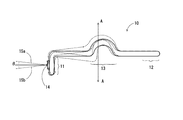
図1に示すヒートパイプ10の模式図を参照しながら第1屈曲部13が撓む方向について説明する。図1に示すようにヒートパイプ10は略線状であって、一端側が入熱部11となり、他端側が排熱部12となる。ヒートパイプ10の略中央に第1屈曲部13が設けられる。第1屈曲部13は図1において紙面上方に、半円状に屈曲した形状である。図1に破線で示すのは第1屈曲部が撓んだ状態である。なお、入熱部11には光源14が取り付けられており、排熱部12はヒートシンク(図示せず)に固定されている。図1に示すように、第1屈曲部13はその突出方向(図1の紙面上方)及びその反対の方向であるA−A方向に撓む。これに伴って、入熱部11側がA−A方向に移動することとなり、光源14の光軸15の角度が調整される。第1屈曲部13は、光軸15の角度の調整可能な範囲(角θ)が5°〜30°、好ましく5°〜20°となるように屈曲させることができる。
In one aspect of the invention, the heat pipe has a first bend on the outside of the housing. The outer shape of the heat pipe is generally linear, and one end side of the heat pipe is a heat input part, and the other end side is a heat exhaust part. The heat input part is attached to the light source, and the exhaust heat part is attached to the heat dissipation part. The first bent portion can be formed by bending a part of the heat pipe into, for example, a semicircular shape, a dogleg shape, an S shape, or the like. The first bent portion may be composed of a plurality of bent portions. The first bent portion is easily bent (deformed) in a specific direction by the bent shape. The shape of the heat pipe may be a spiral shape. If it does in this way, it will become easy to bend a heat pipe to the perimeter direction.
The direction in which the first
本発明の一態様では、ヒートパイプは第2方向に撓む第2屈曲部を有する。第2屈曲部も第1屈曲部と同様にハウジングの外側に形成される。第2方向は第1方向と垂直であることが好ましい。このようにすれば、第1屈曲部と第2屈曲部を利用して全周方向にわたって光軸の角度調整が可能となる。第2屈曲部は第1屈曲部と同様に、ヒートパイプの一部を屈曲して形成される。第2屈曲部を複数の屈曲部からなることとしても良い。第2屈曲部の形状は第1屈曲部の形状と異なっていても良い。第2屈曲部は、光源の光軸の角度の調整可能な範囲(角θ)が5°〜30°、好ましく5°〜20°となるように屈曲させることができる。なお、第1屈曲部が形成される位置と第2屈曲部が形成される位置はハウジングの外側であればよく、第1屈曲部と第2屈曲部が配置される順序は限定されない。第1屈曲部と第2屈曲部が配置される間隔も特に限定されず、設置スペース等を考慮して適宜決定することができる。
なお、ヒートパイプは、第1方向及び第2方向と異なる方向に撓む屈曲部を更に備えていても良い。一方、後述のシール部が可撓性のブーツ部材からなる場合は、直線状のヒートパイプを使用することができる。
In one embodiment of the present invention, the heat pipe has a second bent portion that bends in the second direction. The second bent portion is also formed outside the housing in the same manner as the first bent portion. The second direction is preferably perpendicular to the first direction. In this way, it is possible to adjust the angle of the optical axis over the entire circumferential direction using the first bent portion and the second bent portion. Similar to the first bent portion, the second bent portion is formed by bending a part of the heat pipe. The second bent portion may be composed of a plurality of bent portions. The shape of the second bent portion may be different from the shape of the first bent portion. The second bent portion can be bent so that the adjustable range (angle θ) of the angle of the optical axis of the light source is 5 ° to 30 °, preferably 5 ° to 20 °. The position where the first bent portion and the position where the second bent portion are formed need only be outside the housing, and the order in which the first bent portion and the second bent portion are arranged is not limited. An interval at which the first bent portion and the second bent portion are arranged is not particularly limited, and can be appropriately determined in consideration of an installation space or the like.
The heat pipe may further include a bent portion that bends in a direction different from the first direction and the second direction. On the other hand, when the seal part described later is made of a flexible boot member, a linear heat pipe can be used.
(シール部)
シール部は、ハウジングと熱導出手段の間をシールする。これにより、ハウジング内が防水される。シール部は可撓性のブーツ部材からなることが好ましい。後述の光軸調節手段による光源の光軸の角度の変化に追従するように、シール部が容易に変形するからである。
(Seal part)
The seal portion seals between the housing and the heat derivation means. Thereby, the inside of a housing is waterproofed. The seal portion is preferably made of a flexible boot member. This is because the seal portion is easily deformed so as to follow the change in the angle of the optical axis of the light source by the optical axis adjusting means described later.
本発明の一態様では、ヒートシンクを使用して、該ヒートシンクの一部を光源に接続し、ヒートシンクの放熱フィンがハウジング外に位置するようにハウジングにヒートシンクを貫設し、可撓性を有するシール部によりヒートシンクとハウジングの間をシールする。この構成により、ヒートシンクのうち、ハウジング内に位置する部分が伝熱部となり、放熱フィンが放熱部となる。これにより、部品点数が削減されて製造コストの低減が図られるとともに、組み付け作業性が向上する。 In one embodiment of the present invention, a heat sink is used, a part of the heat sink is connected to a light source, and the heat sink is penetrated through the housing so that the heat radiating fins of the heat sink are located outside the housing. The part seals between the heat sink and the housing. With this configuration, a portion of the heat sink that is located in the housing serves as a heat transfer portion, and the heat radiation fin serves as a heat dissipation portion. As a result, the number of parts is reduced, the manufacturing cost is reduced, and the assembly workability is improved.
(光軸調整手段)
光軸調整手段は光源の角度を変化させることにより、光軸の角度調整を可能とする。光軸調整手段は公知の構成を採用できる。光軸調整手段による光軸の角度調整は手動又は自動で行うことができる。例えば、車両の積載重量の変化に伴う光軸角度の変化を補正するオートレベリング機能により自動で行っても良い。あるいは、車両のステアリング舵角に連動して進行方向を照らすAFS(アダプティブ・フロントライティングシステム)により自動で行っても良い。
以下に本発明の実施例について説明する。
(Optical axis adjustment means)
The optical axis adjusting means can adjust the angle of the optical axis by changing the angle of the light source. A known configuration can be adopted for the optical axis adjusting means. The angle adjustment of the optical axis by the optical axis adjusting means can be performed manually or automatically. For example, it may be automatically performed by an auto leveling function that corrects a change in the optical axis angle accompanying a change in the load weight of the vehicle. Or you may perform automatically by AFS (adaptive front lighting system) which illuminates the advancing direction in response to the steering angle of a vehicle.
Examples of the present invention will be described below.
本発明の実施例である車両のヘッドライト1の斜視図を図2に示す。図2に示すようにヘッドライト1はアウターレンズ2と光源ユニット3を備える。ヘッドライト1の光源ユニット3の斜視図を図3に示す。図3に示すように、光源ユニット3は、ハウジング20、ヒートパイプ30、ヒートシンク40を備える。ハウジング20は内部に光源21を収納している。光源21は熱伝導性部材22を介してヒートパイプ30の一端部(入熱部31)に取り付けられている。熱伝導性部材22はAl製である。ハウジング20の光源21の光放出側にはレンズ23が設けられる。光源21は表面実装型の白色発光LEDランプである。なお、LEDチップが実装される実装基板24は放熱性を考慮してセラミクス製基板を採用している。ヒートパイプ30は一端側に光源21が取り付けられる入熱部31、他端側に排熱部32、中央部付近に第1屈曲部33及び第2屈曲部34を有する。排熱部32にはヒートシンク40が取り付けられている。ヒートシンク40はAl製であって多数のフィンを備える。なお、ヒートシンク40は車両フレーム(図示せず)に固定されている。
FIG. 2 shows a perspective view of a
第1屈曲部33は車両の進行方向及び地面に垂直な方向である第1方向(図3において符号A‐Aで示す)に略半円状に屈曲している。一方、第2屈曲部34は第1方向及び車両に垂直な第2方向(図3において符号B‐Bで示す。)に略半円状に屈曲している。第1屈曲部33及び第2屈曲部34はともにハウジング20の外側に形成されている。ヒートパイプ30は直径約6mm、長さ約300mmである。ハウジング20はヒートパイプ30が貫通する貫通孔25を備える。貫通孔25には防水パッキン(図示せず)が取り付けられており、貫通孔25からハウジング20内へ水等が浸入することが防止される。また、レンズ23の全縁部がハウジング20へ溶着されている。これらにより、ハウジング20内は防水状態に保たれている。
The first bent portion 33 is bent in a semicircular shape in a first direction (indicated by reference AA in FIG. 3) that is a direction in which the vehicle travels and a direction perpendicular to the ground. On the other hand, the second
次にヘッドライト1の光軸の角度調整について説明する。図4Aに、図3のIに示した角度から光源ユニット3を見た模式図を示し、図4Bに図3のIIに示した角度から光源ユニット3を見た模式図を示す。図4A及び図4Bにおいて、第1屈曲部33または第2屈曲部34が撓んだ状態を点線で示す。図4Aに示すように、第1屈曲部33はA‐A方向に撓む。排熱部32側は車両ボディー固定されており、図4にa及びbで示すように入熱部31側が移動する。これに伴い、光源21の光軸26は、符号26aから符号26bの範囲で変化する。この範囲で光軸26の角度調整が行われる。光軸26aと光軸26bとのなす角度αは、A‐A方向に約5°〜約20°である。
一方、第2屈曲部34は、図4Bに示すようにB‐B方向に撓む。排熱部32側は車両ボディーに固定されているため、図4にc及びdで示すように入熱部31側が移動する。これに伴い、光源21の光軸26は符号26cから符号26dの範囲で変化する。この範囲で光軸26の角度調整が行われる。光軸26cと光軸26dとのなす角度βは、B‐B方向に約5°〜約20°である。
上述のように光軸26は、A‐A方向及びB‐B方向にそれぞれ約5°〜約20°の範囲で角度調整を行うことができるため、これらを組み合わせることにより、全方向に関して約5°〜約20°の範囲で角度調整を行うことができる。即ち、ヘッドライト1では、装置全体の設置角度を変更することなく、各屈曲部33、34を屈曲させることで、光軸26の角度調整を行うことができるため、作業が煩雑とならない。さらに、一旦組み付けた後に光軸26の角度調整を行うことが容易である。
Next, the angle adjustment of the optical axis of the
On the other hand, the second
As described above, the angle of the
ところで、光源21で発生した熱は、熱伝導性部材22を介して、ヒートパイプ30の入熱部31へ伝播する。入熱部31へ到達した熱はヒートパイプ30の放熱作用により、排熱部32へ効率的に移動する。排熱部32に移動した熱はヒートシンク40を介して外部へ放出される。このように、ヘッドライト1では光源21の熱は効率的に外部へ放出されることとなり、光源21の過熱が防止される。
以上のように、ヘッドライト1は、簡易な構成であるにもかかわらず、ヒートパイプ30による優れた放熱性と光軸26の角度調整の容易性とを兼ね備える。
By the way, the heat generated by the
As described above, the
本発明の他の実施例であるダウンライト50の側方から見た一部透過図を図5Aに示す。図5Aに示したIIIの角度から見た一部透過図を図5Bに示す。ダウンライト50は室内天井に埋め込まれている。ダウンライト50はリフレクタ51、ハウジング200、ヒートパイプ300、ヒートシンク400を備える。リフレクタ51は椀型の形状を有し、室内側に開口するように設置される。リフレクタ51の最深部にハウジング200が設置される。ハウジング200は内部に光源210を収納している。光源210は熱伝導性部材220を介してヒートパイプ300の一端部(入熱部310)に取り付けられている。ハウジング200の光源210の光放出側にはレンズ230が設けられる。光源210は表面実装型の白色発光LEDランプである。ヒートパイプ300は一端側に光源210が取り付けられる入熱部310、他端側に排熱部320、中央部付近に第1屈曲部330及び第2屈曲部340を有する。排熱部320にはヒートシンク400が取り付けられている。ヒートシンク400はAl製であって多数のフィンを備え放熱特性に優れる。なお、ヒートシンク400は固定部材321により天井に固定されている。
A partially transparent view seen from the side of a
第1屈曲部330は水平方向である第1方向(図5Aにおいて符号A’‐A’で示す方向)に略半円状に屈曲している。一方、第2屈曲部340は水平方向であって第1方向に垂直な第2方向(図5Bにおいて符号B’‐B’で示す方向)に略半円状に屈曲している。第1屈曲部330及び第2屈曲部340はリフレクタ51の外側に形成されている。ヒートパイプ300は直径約4mm、長さ約300mmである。
The first
次にダウンライト50の光軸の角度調整について説明する。図6、図7に、図5A、5Bに対応する角度調整時の模式図をそれぞれ示す。図6及び図7において、各屈曲部330、340が撓んだ状態を点線及び太線で示す。図6に示すように、第1屈曲部330はA’‐A’方向に撓む。排熱部320はヒートシンク400を介して天井に固定されており、図6に点線及び太線で示すように入熱部310に取り付けられた光源210の光軸26の角度が変化する。これにより、第1屈曲部330が撓むことによって、光軸26は符号26a’から符号26b’の範囲で変化する。この範囲で光軸26の角度調整が行われる。光軸26a’と光軸26b’とのなす角度α’は、A’‐A’方向に約5°〜約20°である。同様に、図7に示すように、第2屈曲部340がB’‐B’方向に撓むことにより、図7に点線及び太線で示すように入熱部310に取り付けられた光源210の光軸26の角度が変化する。光軸26は符号26c’から符号26d’の範囲で変化し、この範囲で光軸26の角度調整が行われる。光軸26c’と光軸26d’とのなす角度β’は、B’‐B’方向に約5°〜約20°である。これらのように光軸26は、A’‐A’方向及びB’‐B’方向にそれぞれ約5°〜約20°の範囲で角度調整を行うことができるため、これらを組み合わせることにより、全方向に関して約5°〜約20°の範囲で角度調整を行うことができる。即ち、ダウンライト50では、装置全体の設置角度を変更することなく、各屈曲部330、340を屈曲させることで、光軸26の角度調整を行うことができるため、作業が煩雑とならない。さらに、一旦組み付けた後に光軸26の角度調整を行うことが容易である。一方、光源210の熱はヒートパイプ300によりヒートシンク400から放出される。これにより、光源210の放熱が効率的に行われることとなる。
以上のように、ダウンライト50は、簡易な構成であるにもかかわらず、ヒートパイプ300による優れた放熱性と光軸26の角度調整の容易性とを兼ね備える。
Next, the angle adjustment of the optical axis of the
As described above, the
本発明の実施例の一つである車両用ヘッドライト800の縦断面図を図8に示す。ヘッドライト800は、ハウジング820、アウターレンズ826、ヒートパイプ830、ヒートシンク840及び光源ユニット850を備える。光源ユニット850は、平板状のベース824を備え、その中央の台座部に光源821が設けられる。光源821は白色LEDランプである。光源ユニット850は前方(アウターレンズ826方向)にレンズ823を備える。光源821の光放出側にはリフレクタ851が設けられる。リフレクタ851は前方が開口した半ドーム形状を有し、光源821の光をレンズ823の方向へ反射する。
光源ユニット850の一部と、ヒートパイプ830とヒートシンク840とを抜き出してその斜視図を図9に示す。図8、9に示すようにベース824の4つの角部に取り付けられた4個のシャフト860a〜dにより、ベース824はハウジング820へ固定されている。シャフト860cのハウジング820側の端部には光軸調節機861が取り付けられている。光軸調節機861は車両の積載重量の変化に応じてシャフト860cを押し出し又は引き入れる。
ヒートパイプ830は螺旋状であって、ハウジング820に形成された貫通孔825を介してハウジング820を貫通している。ヒートパイプ830の光源821側の端部が入熱部831であり、ヒートシンク840側の端部が排熱部832である。入熱部831はベース824の背面の中央に埋め込まれている。一方、排熱部832は、ハウジング820の背面側に設けられたヒートシンク840に埋め込まれている。ヒートシンク840はAl製で、板状の放熱フィン841を複数個備える。放熱フィン841は水平面に垂直な方向に立設され、互いに平行である。なお、防水シール870によってハウジング820とヒートパイプ830の間がシールされている。
FIG. 8 is a longitudinal sectional view of a
A perspective view of a part of the
The
次にヘッドライト800の光軸の角度調整について説明する。ヘッドライト800を備える車両の積載重量が増大すると、これに応じて光軸調節機861がシャフト860cを引き入れる。これにより、光源ユニット850全体の設置角度が変化し、放出される光の光軸821aが下方に向くように変化する。これに伴って、螺旋状であるヒートパイプ830は撓む(変形する)。一方、車両の積載重量が減少すると、これに応じて光軸調節機861がシャフト860cを押し出す。これにより、光源ユニット850全体の角度が変化し、放出される光の光軸821aが上方に向くように変化する。これに追従するように、螺旋形状のヒートパイプ830が撓む(変形する)。このように、ヒートパイプ830が撓むことにより、ヘッドライト800全体の角度を変更することなく、容易に光軸821aの角度調整がなされる。一方、貫通孔825は防水シール870によりシールされているため、ハウジング820ないが防水される。また、ヘッドライト800においても、ヘッドライト1と同様に光源821の熱はヒートパイプ830及びヒートシンク840により効率的に外部へ放出されることとなり、高い放熱効果を奏する。
なお、本実施例では、光軸調節機861により車両の積載重量の変化に応じて自動的に光軸821aの角度調整を行うこととしたが、これに限定されない。例えば、シャフト860cにネジ機構を設けて、シャフト860cを手動で回動させることにより、ベース824の角度を変化させ、光軸821aの角度調整を行うようにしてもよい。
Next, the angle adjustment of the optical axis of the
In the present embodiment, the
本発明の実施例の一つである車両用ヘッドライト900の縦断面図を図10に示す。なお、ヘッドライト800と実質的に同一の部材には同一の符号を付してその説明を省略する。ヘッドライト900はヒートパイプ930を備える。ヒートパイプ930は直線状であって、一端が入熱部931であり、他端が排熱部932である。ヒートパイプ930はハウジング920に形成された貫通孔925を介してハウジング920に貫設されている。入熱部931はベース824の背面の中央に埋め込まれている。一方、排熱部932はハウジング920の後方に設けられたヒートシンク840に埋め込まれている。ブーツ970はハウジング925とヒートパイプ930の間をシールしている。クロロプレンゴム製のブーツ970は蛇腹状であり、可撓性を有する。
FIG. 10 is a longitudinal sectional view of a
ヘッドライト900では、ヘッドライト800と同様に、光軸調整機860により車両の積載重量の変化に応じて自動的に光源ユニット850の角度が調整される。これに追従するように、可撓性のブーツ970が変形する。即ち、光源ユニット850の角度の変化に追従してヒートパイプ930及びヒートシンク840も角度が変化する。このようにブーツ970が変形することにより、ヘッドライト900全体の設置角度を変更することなく、容易に光軸821aの角度調整がなされる。さらにブーツ970はハウジング925とヒートパイプ930の間をシールしているため、ハウジング925が防水される。また、ヘッドライト900においても、ヘッドライト1、800と同様に光源821の熱はヒートパイプ930及びヒートシンク840により効率的に外部へ放出されることとなり、高い放熱効果を奏する。
In the
本発明の実施例の一つである車両用ヘッドライト950の縦断面図を図11に示す。なお、ヘッドライト800、900と実質的に同一の部材には同一の符号を付してその説明を省略する。ヘッドライト950は、ヒートシンク940を備える。ヒートシンク940は、棒状部941と、板状フィン部942及び平板部943を備える。平板部943の一方の面(正面)の中央に棒状部941が突出しており、平板部943の他方の面(裏面)には、垂直方向に向いた複数の板状フィンからなる板状フィン部942が突出している。ヒートシンク940は貫通孔951を介して、ハウジング952に貫設されている。ブーツ971はハウジング952とヒートシンク940との間をシールするように、ヒートシンク940の平板部943の側周面とハウジング952に接着されている。クロロプレンゴム製のブーツ970は蛇腹状であり、可撓性を有する。棒状部941の上面には光源821が配置される
FIG. 11 is a longitudinal sectional view of a
ヘッドライト950では、ヘッドライト900と同様に、光源ユニット850の角度の変化に追従してヒートシンク940も角度が変化する。このように、ブーツ970が変形することにより、ヘッドライト900全体の設置角度を変更することなく、容易に光軸821aの角度調整がなされる。さらに、光源821の熱はヒートシンク940の棒状部941に伝播され、棒状部941から平板部943を経て板状フィン部942へ進んだ後、板状フィン部942から外部へ放出される。ヘッドライト1、800、900と同様に光源821の熱はヒートシンク940により効率的に外部へ放出されることとなり、高い放熱効果を奏する。このように、棒状部941は板状フィン部942へ光源821の熱を伝播する伝熱部として機能することとなる。すなわち、ヒートシンク940は伝熱部と放熱部とを兼ね備えることとなる。これにより、部品点数が削減されることにより、製造コストが低減されるとともに、組み付け工程が簡略化される。また、ヘッドライト900と同様に、ブーツ970によりハウジング952とヒートシンク940の間がシールされるため、ハウジング952内が防水される。
In the
本発明の発光装置は、様々な照明用途にその利用が図られる。 The light emitting device of the present invention can be used for various lighting applications.
1、800、900、950 ヘッドライト
2、826 アウターレンズ
3、850 光源ユニット
10、30、300、830、930 ヒートパイプ
12、32、320、832、932 排熱部
13、33、330 第1屈曲部
14、21、210、821 光源
15a、15b、26、26a、26b、26c、26d、26a’、26b’、26c’、26d’、821a 光軸
20、200、820、920、952 ハウジング
22、220 熱伝導性部材
31、310、831、931 入熱部
34、340 第2屈曲部
321 固定部材
40、400、840、940 ヒートシンク
50 ダウンライト
870 防水シール
970、971 ブーツ
860a、860b、860c、860d シャフト
861 光軸調整機
1, 800, 900, 950
Claims (12)
前記光源を収納するハウジングと、
伝熱部と放熱部とからなり、前記ハウジングを貫通する熱導出手段であって、該伝熱部は前記光源に取り付けられ、該放熱部は前記ハウジングの外側に位置する熱導出手段と、
前記熱導出手段と前記ハウジングの間をシールするシール部と、及び
前記光源の光軸を調節する光軸調整手段と、
を備え、
前記光軸調整手段による前記光源の光軸の角度の変化に追従するように、前記伝熱部又は前記シール部が変形する、ことを特徴とする発光装置。 A light source;
A housing for housing the light source;
A heat deriving unit comprising a heat transfer unit and a heat dissipating unit and penetrating the housing, the heat transfer unit being attached to the light source, and the heat dissipating unit being located outside the housing;
A seal portion that seals between the heat deriving unit and the housing; and an optical axis adjusting unit that adjusts an optical axis of the light source;
With
The light-emitting device, wherein the heat transfer section or the seal section is deformed so as to follow a change in an angle of an optical axis of the light source by the optical axis adjusting means.
Priority Applications (2)
| Application Number | Priority Date | Filing Date | Title |
|---|---|---|---|
| JP2007221191A JP2008218386A (en) | 2007-02-09 | 2007-08-28 | Light emitting device |
| US12/068,652 US20080247177A1 (en) | 2007-02-09 | 2008-02-08 | Luminescent device |
Applications Claiming Priority (2)
| Application Number | Priority Date | Filing Date | Title |
|---|---|---|---|
| JP2007030068 | 2007-02-09 | ||
| JP2007221191A JP2008218386A (en) | 2007-02-09 | 2007-08-28 | Light emitting device |
Publications (2)
| Publication Number | Publication Date |
|---|---|
| JP2008218386A true JP2008218386A (en) | 2008-09-18 |
| JP2008218386A5 JP2008218386A5 (en) | 2009-12-03 |
Family
ID=39838166
Family Applications (1)
| Application Number | Title | Priority Date | Filing Date |
|---|---|---|---|
| JP2007221191A Withdrawn JP2008218386A (en) | 2007-02-09 | 2007-08-28 | Light emitting device |
Country Status (1)
| Country | Link |
|---|---|
| JP (1) | JP2008218386A (en) |
Cited By (12)
| Publication number | Priority date | Publication date | Assignee | Title |
|---|---|---|---|---|
| JP2011138777A (en) * | 2009-12-30 | 2011-07-14 | Neobulb Technologies Inc | Lighting system |
| JP2012504315A (en) * | 2008-09-30 | 2012-02-16 | オスラム・シルバニア・インコーポレイテッド | LED source with integrated heat pipe |
| JP2012518882A (en) * | 2009-02-24 | 2012-08-16 | コーニンクレッカ フィリップス エレクトロニクス エヌ ヴィ | Orientable magnetic table, light source, base and lighting device for light emitting elements |
| JP2012531703A (en) * | 2009-06-25 | 2012-12-10 | コーニンクレッカ フィリップス エレクトロニクス エヌ ヴィ | Thermal management device |
| CN103292195A (en) * | 2013-06-21 | 2013-09-11 | 中国科学院工程热物理研究所 | Split type LED lamp |
| JP2015526854A (en) * | 2012-07-25 | 2015-09-10 | シェンツェン イーク エレクトロオプティカル テクノロジー カンパニー リミテッド | LED headlamps for automobiles |
| JP2015530712A (en) * | 2012-08-30 | 2015-10-15 | サビック グローバル テクノロジーズ ベスローテン フェンノートシャップ | Heat dissipation system for light, headlamp assembly including the same, and method of dissipating heat |
| JP2016024890A (en) * | 2014-07-17 | 2016-02-08 | スタンレー電気株式会社 | Vehicle lighting appliance |
| JP2016066527A (en) * | 2014-09-25 | 2016-04-28 | スタンレー電気株式会社 | Vehicle lamp fitting |
| JP2018006136A (en) * | 2016-06-30 | 2018-01-11 | ウシオ電機株式会社 | Floodlight device |
| JP2019033061A (en) * | 2017-08-07 | 2019-02-28 | 株式会社小糸製作所 | Vehicle lamp fitting |
| US10760766B2 (en) | 2016-06-30 | 2020-09-01 | Ushio Denki Kabushiki Kaisha | Floodlight device with two optical systems that condense and collimate laser light |
Citations (5)
| Publication number | Priority date | Publication date | Assignee | Title |
|---|---|---|---|---|
| JPS61143689A (en) * | 1984-12-18 | 1986-07-01 | Sumitomo Electric Ind Ltd | Heat pipe |
| JP2001203307A (en) * | 2000-01-18 | 2001-07-27 | Kitagawa Ind Co Ltd | Heat pipe |
| JP2004127782A (en) * | 2002-10-04 | 2004-04-22 | Ichikoh Ind Ltd | Vehicle lamp and lighting device |
| JP2004311224A (en) * | 2003-04-08 | 2004-11-04 | Koito Mfg Co Ltd | Vehicle headlight device |
| JP2005235431A (en) * | 2004-02-17 | 2005-09-02 | Ichikoh Ind Ltd | Vehicular lamp |
-
2007
- 2007-08-28 JP JP2007221191A patent/JP2008218386A/en not_active Withdrawn
Patent Citations (5)
| Publication number | Priority date | Publication date | Assignee | Title |
|---|---|---|---|---|
| JPS61143689A (en) * | 1984-12-18 | 1986-07-01 | Sumitomo Electric Ind Ltd | Heat pipe |
| JP2001203307A (en) * | 2000-01-18 | 2001-07-27 | Kitagawa Ind Co Ltd | Heat pipe |
| JP2004127782A (en) * | 2002-10-04 | 2004-04-22 | Ichikoh Ind Ltd | Vehicle lamp and lighting device |
| JP2004311224A (en) * | 2003-04-08 | 2004-11-04 | Koito Mfg Co Ltd | Vehicle headlight device |
| JP2005235431A (en) * | 2004-02-17 | 2005-09-02 | Ichikoh Ind Ltd | Vehicular lamp |
Cited By (14)
| Publication number | Priority date | Publication date | Assignee | Title |
|---|---|---|---|---|
| JP2012504315A (en) * | 2008-09-30 | 2012-02-16 | オスラム・シルバニア・インコーポレイテッド | LED source with integrated heat pipe |
| JP2012518882A (en) * | 2009-02-24 | 2012-08-16 | コーニンクレッカ フィリップス エレクトロニクス エヌ ヴィ | Orientable magnetic table, light source, base and lighting device for light emitting elements |
| US9157598B2 (en) | 2009-06-25 | 2015-10-13 | Koninklijke Philips N.V. | Heat managing device |
| JP2012531703A (en) * | 2009-06-25 | 2012-12-10 | コーニンクレッカ フィリップス エレクトロニクス エヌ ヴィ | Thermal management device |
| JP2011138777A (en) * | 2009-12-30 | 2011-07-14 | Neobulb Technologies Inc | Lighting system |
| JP2015526854A (en) * | 2012-07-25 | 2015-09-10 | シェンツェン イーク エレクトロオプティカル テクノロジー カンパニー リミテッド | LED headlamps for automobiles |
| JP2015530712A (en) * | 2012-08-30 | 2015-10-15 | サビック グローバル テクノロジーズ ベスローテン フェンノートシャップ | Heat dissipation system for light, headlamp assembly including the same, and method of dissipating heat |
| US10591124B2 (en) | 2012-08-30 | 2020-03-17 | Sabic Global Technologies B.V. | Heat dissipating system for a light, headlamp assembly comprising the same, and method of dissipating heat |
| CN103292195A (en) * | 2013-06-21 | 2013-09-11 | 中国科学院工程热物理研究所 | Split type LED lamp |
| JP2016024890A (en) * | 2014-07-17 | 2016-02-08 | スタンレー電気株式会社 | Vehicle lighting appliance |
| JP2016066527A (en) * | 2014-09-25 | 2016-04-28 | スタンレー電気株式会社 | Vehicle lamp fitting |
| JP2018006136A (en) * | 2016-06-30 | 2018-01-11 | ウシオ電機株式会社 | Floodlight device |
| US10760766B2 (en) | 2016-06-30 | 2020-09-01 | Ushio Denki Kabushiki Kaisha | Floodlight device with two optical systems that condense and collimate laser light |
| JP2019033061A (en) * | 2017-08-07 | 2019-02-28 | 株式会社小糸製作所 | Vehicle lamp fitting |
Similar Documents
| Publication | Publication Date | Title |
|---|---|---|
| JP2008218386A (en) | Light emitting device | |
| US20080247177A1 (en) | Luminescent device | |
| JP4569683B2 (en) | Light emitting element lamp and lighting apparatus | |
| JP4605120B2 (en) | Vehicle lighting | |
| JP4497073B2 (en) | Vehicle lighting | |
| JP2010153044A (en) | Light source unit and luminaire | |
| JP4740095B2 (en) | LED lights for vehicles | |
| JP2004127782A (en) | Vehicle lamp and lighting device | |
| JP2007220618A (en) | Vehicular led lighting fixture | |
| JP5415019B2 (en) | LED light source device | |
| JP2009087620A (en) | Headlight for vehicle | |
| JP2009032590A (en) | Led lamp attained by multi-stage layer substrate, and diffusing heat instantly | |
| JP2011175868A (en) | Lighting equipment | |
| JP2007109613A (en) | Lamp for vehicle | |
| JP6283357B2 (en) | Vehicle lighting | |
| JP2007172932A (en) | Vehicular headlight | |
| JP2008135260A (en) | Headlamp for vehicle | |
| JP2010146807A (en) | Vehicle lamp | |
| JP2011134637A (en) | Lighting fixture for vehicle | |
| JP2009087733A (en) | Vehicle lighting device | |
| JP2005251637A (en) | Lighting system | |
| JP2016162597A (en) | Lighting device | |
| JP2010182686A (en) | Led lamp achieved by multi-stage layer substrate and dissipating heat immediately | |
| JP7027620B2 (en) | LED lighting device | |
| JP4780777B2 (en) | LED lights for vehicles |
Legal Events
| Date | Code | Title | Description |
|---|---|---|---|
| A521 | Written amendment |
Free format text: JAPANESE INTERMEDIATE CODE: A523 Effective date: 20091019 |
|
| A621 | Written request for application examination |
Free format text: JAPANESE INTERMEDIATE CODE: A621 Effective date: 20091215 |
|
| A977 | Report on retrieval |
Free format text: JAPANESE INTERMEDIATE CODE: A971007 Effective date: 20110209 |
|
| A131 | Notification of reasons for refusal |
Free format text: JAPANESE INTERMEDIATE CODE: A131 Effective date: 20110308 |
|
| A761 | Written withdrawal of application |
Free format text: JAPANESE INTERMEDIATE CODE: A761 Effective date: 20110414 |