JP2008207213A - Welding apparatus - Google Patents
Welding apparatus Download PDFInfo
- Publication number
- JP2008207213A JP2008207213A JP2007046455A JP2007046455A JP2008207213A JP 2008207213 A JP2008207213 A JP 2008207213A JP 2007046455 A JP2007046455 A JP 2007046455A JP 2007046455 A JP2007046455 A JP 2007046455A JP 2008207213 A JP2008207213 A JP 2008207213A
- Authority
- JP
- Japan
- Prior art keywords
- mig
- tig
- current
- welding
- current value
- Prior art date
- Legal status (The legal status is an assumption and is not a legal conclusion. Google has not performed a legal analysis and makes no representation as to the accuracy of the status listed.)
- Pending
Links
Images


Abstract
Description
本発明は、溶接対象材の溶接対象箇所に対してMIG溶接とTIG溶接とを施すことが可能な溶接装置に関する。 The present invention relates to a welding apparatus capable of performing MIG welding and TIG welding on a welding target portion of a welding target material.
TIG溶接とMIG溶接とを施すことが可能な溶接装置は、溶接速度の向上や溶け込み深さをより深くすることなどに有利である。図4は、従来の溶接装置の一例を示している。同図に示された溶接装置Xは、MIG電極91、TIG電極92、MIG電源MP、およびTIG電源TPを備えている。MIG電極91は、消耗型電極としてのワイヤWを支持しつつ、ワイヤWと導通している。TIG電極92は、その先端がたとえばタングステンからなる非消耗型電極である。MIG電源MPおよびTIG電源TPは、たとえば商用三相交流電源の二相に接続されている。MIG電源MPは、MIG電極91を介してワイヤWと溶接対象材Pとの間にMIGアークを発生させるための交流のMIG電圧を印加する。TIG電源TPは、TIG電極92と溶接対象材Pとの間にTIGアークを発生させるための交流のTIG電圧を印加する。溶接装置Xによれば、溶接対象材Pの同一箇所に対して、MIG溶接とTIG溶接とを施すことが可能である。
A welding apparatus capable of performing TIG welding and MIG welding is advantageous in improving the welding speed and increasing the penetration depth. FIG. 4 shows an example of a conventional welding apparatus. The welding apparatus X shown in the figure includes a
しかしながら、上記MIG電圧および上記TIG電圧は交流であるため、それぞれが周期的に0となる。上記MIG電圧および上記TIG電圧が0である瞬間は、上記MIGアークおよび上記TIGアークが途切れてしまう。このようなアークは不安定であるため、MIG溶接およびTIG溶接によって形成されたビードが乱れるおそれがある。また、MIIG電極91とTIG電極92との相対的な電位差が周期的に変動する。これにより、上記MIGアークと上記TIGアークとの間に引力と斥力とが交互に作用することとなる。この結果、溶接対象材Pに対してこれらのアークの位置が不安定となるという不具合があった。
However, since the MIG voltage and the TIG voltage are alternating current, each periodically becomes zero. At the moment when the MIG voltage and the TIG voltage are 0, the MIG arc and the TIG arc are interrupted. Since such an arc is unstable, the bead formed by MIG welding and TIG welding may be disturbed. Further, the relative potential difference between the
本発明は、上記した事情のもとで考え出されたものであって、安定したMIG溶接およびTIG溶接を施すことが可能な溶接装置を提供することをその課題とする。 The present invention has been conceived under the above circumstances, and an object thereof is to provide a welding apparatus capable of performing stable MIG welding and TIG welding.
本発明によって提供される溶接装置は、送給されるワイヤを保持し、かつこのワイヤに導通するMIG電極と、TIG電極と、上記MIG電極を介して上記ワイヤと上記溶接対象材との間に、振幅および周期を有するMIG電流を流すためのMIG電源と、上記TIG電極と溶接対象材との間に、振幅および周期を有するTIG電流を流すためのTIG電源と、を備える溶接装置であって、上記MIG電流は、上記溶接対象材に対して上記ワイヤが常に陽極側となる状態で流され、かつ絶対値が0より大であるMIGベース電流値とこのMIGベース電流値よりも絶対値が大であるMIGピーク電流値とを交互にとる波形とされており、上記TIG電流は、上記溶接対象材に対して上記TIG電極が常に陰極側となる状態で流され、かつ絶対値が0より大であるTIGベース電流値とこのTIGベース電流値よりも絶対値が大であるTIGピーク電流値とを交互にとる波形とされており、上記MIG電流が上記MIGピーク電流値をとるときと、上記TIG電流が上記TIGピーク電流値をとるときとは、互いにシフトされていることを特徴としている。 The welding apparatus provided by the present invention holds a wire to be fed and is electrically connected to the MIG electrode, the TIG electrode, and the wire and the material to be welded via the MIG electrode. A welding apparatus comprising: a MIG power source for flowing a MIG current having an amplitude and a period; and a TIG power source for flowing a TIG current having an amplitude and a period between the TIG electrode and the material to be welded. The MIG current is flowed in a state where the wire is always on the anode side with respect to the material to be welded, and the absolute value is larger than 0 and the absolute value is larger than the MIG base current value. The TIG current is made to flow alternately in a state where the TIG electrode is always on the cathode side with respect to the material to be welded, and the waveform takes alternately the large MIG peak current value. Is a waveform in which a TIG base current value having an absolute value larger than 0 and a TIG peak current value having an absolute value larger than the TIG base current value are alternately arranged, and the MIG current takes the MIG peak current value. And when the TIG current takes the TIG peak current value are shifted from each other.
このような構成によれば、上記MIG電流および上記TIG電流は、それぞれが流れる方向が一定であるとともに、その値は常に0より大きい。このため、TIGアークおよびMIGアークが途切れることがない。したがって、MIG溶接およびTIG溶接を安定して行うことができる。 According to such a configuration, the MIG current and the TIG current have a constant flowing direction, and their values are always larger than zero. For this reason, the TIG arc and the MIG arc are not interrupted. Therefore, MIG welding and TIG welding can be performed stably.
特に、MIG溶接においては、MIGアークが途切れてしまうと、その後にMIGアークを再度形成することが困難である。また、ワイヤの先端から延びるMIGアークの長さが不安定となる。このため、MIGアークの再形成を繰り返す溶接態様は、安定した溶接に不向きである。これに対し、本発明によれば、溶接作業中においてMIGアークが途切れることがなく、再形成が繰り返されることもない。したがって、溶接の安定化に適している。 In particular, in MIG welding, if the MIG arc is interrupted, it is difficult to form the MIG arc again thereafter. Further, the length of the MIG arc extending from the tip of the wire becomes unstable. For this reason, the welding mode which repeats the re-formation of the MIG arc is not suitable for stable welding. On the other hand, according to the present invention, the MIG arc is not interrupted during the welding operation, and the re-formation is not repeated. Therefore, it is suitable for stabilization of welding.
また、上記MIG電流が上記MIGピーク電流値となるときと、上記TIG電流が上記TIGピーク電流値となるときとは、互いにシフトされている。これにより、TIGアークの強さが最大となるときと、MIGアークの強さが最大となるときとはタイミングが異なる。そうすると、TIGアークとMIGアークとが互いに及ぼしあう斥力を弱めることが可能である。したがって、MIG溶接とTIG溶接とを安定して施すことが可能であり、溶接ビードが乱れることを防止することができる。 Further, the time when the MIG current becomes the MIG peak current value and the time when the TIG current becomes the TIG peak current value are shifted from each other. As a result, the timing differs between when the strength of the TIG arc is maximized and when the strength of the MIG arc is maximized. Then, the repulsive force that the TIG arc and the MIG arc exert on each other can be weakened. Therefore, MIG welding and TIG welding can be performed stably, and the weld bead can be prevented from being disturbed.
さらに、上記TIG電極を常に陰極側として使用することにより、上記TIG電極の先端が溶解することを防止できる。これにより、溶融したTIG電極の一部が溶接ビードに巻き込まれるといった不具合を回避できる。 Further, by always using the TIG electrode as the cathode side, it is possible to prevent the tip of the TIG electrode from being dissolved. Thereby, the malfunction that some molten TIG electrodes are caught in a weld bead can be avoided.
本発明のその他の特徴および利点は、添付図面を参照して以下に行う詳細な説明によって、より明らかとなろう。 Other features and advantages of the present invention will become more apparent from the detailed description given below with reference to the accompanying drawings.
以下、本発明の好ましい実施の形態につき、図面を参照して具体的に説明する。 Hereinafter, preferred embodiments of the present invention will be specifically described with reference to the drawings.
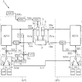
図1および図2は、本発明に係る溶接装置の一例を示している。本実施形態の溶接装置Aは、MIG電極1、TIG電極2、シールドノズル3、MIG電源APS、TIG電源BPS、をおよびワイヤ送給装置AWFを備えており、溶接対象材Pに対してMIG溶接とTIG溶接とを同時に施すことが可能に構成されている。なお、図1においては、MIG電源APS、TIG電源BPS、およびワイヤ供給装置AWFを省略している。
1 and 2 show an example of a welding apparatus according to the present invention. The welding apparatus A according to the present embodiment includes the
MIG電極1は、ワイヤWを支持するとともに、ワイヤWとMIG電源APSとを導通させるためのものである。MIG電極1は、CuまたはCu合金などからなる。MIG電極1には、ワイヤWを挿通可能としつつ、十分に導通させることが可能なサイズとされた貫通孔が形成されている。ワイヤWを消耗型電極として使用することにより、ワイヤWと溶接対象材Pとの間にMIG溶接を行うためのMIGアークを生成可能である。
The
TIG電極2は、溶接対象材Pに対してTIGアークを発生させることによりTIG溶接を行うためのものである。TIG電極2の先端には、非消耗型電極であるタングステン電極21が設けられている。
The
シールドノズル3は、たとえばArなどのシールドガスGの噴出方向を規定するためのものである。シールドノズル3は、MIG電極1およびTIG電極2を囲う略円筒形状とされている。
The
図2に示すように、MIG電源APSは、MIG溶接を行うためのMIG電流AIwをMIG電極1と溶接対象材Pとの間に流すための電源である。MIG電源APSは、出力制御回路AINV、電圧検出回路VD、電流検出回路AID、切替回路ASW、電流誤差増幅回路AEI、ピーク電流設定回路AIP、ベース電流設定回路AIB、変調回路MC、および送給制御回路AWCを備えている。
As shown in FIG. 2, the MIG power source APS is a power source for causing the MIG current AIw for performing MIG welding to flow between the
出力制御回路AINVは、たとえば入力された商用電源(図示略)をMIG溶接に適した出力に制御された電力として供給するためのものであり、たとえばインバータ制御回路が用いられる。 The output control circuit AINV is for supplying, for example, an input commercial power source (not shown) as electric power controlled to an output suitable for MIG welding, and an inverter control circuit is used, for example.
電圧検出回路VDは、MIG電極1と溶接対象材Pとの間の電圧であるMIG電圧AVwを検出し、このMIG電圧AVwを平均化した電圧検出信号Vdを出力する。MIG電源APS外には、電圧設定回路VSが設けられている。電圧設定回路VSからは、電圧設定信号Vsが出力される。
The voltage detection circuit VD detects the MIG voltage AVw which is a voltage between the
電圧検出信号Vdと電圧設定信号Vsとは、変調回路MCに入力される。変調回路MCは、電圧誤差増幅回路EV、V/F変換回路VF、ピーク電流通電時間設定回路TP、およびモノマルチバイブレータMMを備えている。電圧誤差増幅回路EVは、目標値信号としての電圧設定信号Vsとフィードバック信号としての電圧検出信号Vdとの誤差を増幅し、電圧誤差増幅信号Evを出力する。V/F変換回路VFは、電圧誤差増幅信号Evを入力信号とするV/F変換を行い、V/F変換信号Vfを出力する。ピーク電流通電時間設定回路TPは、あらかじめ定められたピーク電流通電時間設定信号Tpを出力する。モノマルチバイブレータMMは、パルス周期信号ATfを出力する。パルス周期信号ATfは、V/F変換信号VfがLowレベルからHighレベルへと変わることをトリガとして、ピーク電流通電時間設定信号Tpによって指定された時間だけHighレベルとなるように、モノマルチバイブレータMMによって生成される。 The voltage detection signal Vd and the voltage setting signal Vs are input to the modulation circuit MC. The modulation circuit MC includes a voltage error amplification circuit EV, a V / F conversion circuit VF, a peak current conduction time setting circuit TP, and a mono multivibrator MM. The voltage error amplification circuit EV amplifies an error between the voltage setting signal Vs as a target value signal and the voltage detection signal Vd as a feedback signal, and outputs a voltage error amplification signal Ev. The V / F conversion circuit VF performs V / F conversion using the voltage error amplification signal Ev as an input signal, and outputs a V / F conversion signal Vf. The peak current conduction time setting circuit TP outputs a predetermined peak current conduction time setting signal Tp. The mono multivibrator MM outputs a pulse period signal ATf. The pulse period signal ATf is a mono-multivibrator MM so as to become a High level only for a time specified by the peak current energization time setting signal Tp, triggered by the change of the V / F conversion signal Vf from the Low level to the High level. Generated by.
ピーク電流設定回路AIPは、あらかじめ定められたピーク電流設定信号AIpを出力する。ベース電流設定回路AIBは、あらかじめ定められたベース電流設定信号AIbを出力する。切替回路ASWは、パルス周期信号ATfがHighレベルのときには、a側に接続されて、ピーク電流設定信号AIpを電流制御設定信号AIscとして出力し、パルス周期信号ATfがLowレベルのときには、b側に接続されて、ベース電流設定信号AIbを電流制御設定信号AIscとして出力する。 The peak current setting circuit AIP outputs a predetermined peak current setting signal AIp. The base current setting circuit AIB outputs a predetermined base current setting signal AIb. The switching circuit ASW is connected to the a side when the pulse cycle signal ATf is at the high level, and outputs the peak current setting signal AIp as the current control setting signal AIsc, and to the b side when the pulse cycle signal ATf is at the low level. The base current setting signal AIb is output as the current control setting signal AIsc.
電流検出回路AIDは、MIG電流AIwを検出して、電流検出信号AIdを出力する。電流誤差増幅回路AEIは、フィードバック信号である電流検出信号AIdと、目標値信号である電流制御設定信号AIscとの誤差を増幅して、電流誤差増幅信号AEiを出力する。この電流誤差増幅信号AEiにしたがって出力制御回路AINVによりMIG電圧AVwが制御される。 The current detection circuit AID detects the MIG current AIw and outputs a current detection signal AId. The current error amplification circuit AEI amplifies an error between the current detection signal AId as a feedback signal and the current control setting signal AIsc as a target value signal, and outputs a current error amplification signal AEi. The MIG voltage AVw is controlled by the output control circuit AINV in accordance with the current error amplification signal AEi.
送給制御回路AWCには、MIG電源APS外に設けられた送給速度設定回路AWSから送給速度設定信号AWsが入力される。送給制御回路AWCは、送給速度設定信号AWsに基づいて送給制御信号AWcを出力する。送給装置AWFは、送給制御信号AWcに応じた送給速度でワイヤWを送給する。 A feed speed setting signal AWs is input to the feed control circuit AWC from a feed speed setting circuit AWS provided outside the MIG power supply APS. The feed control circuit AWC outputs a feed control signal AWc based on the feed speed setting signal AWs. The feeding device AWF feeds the wire W at a feeding speed according to the feeding control signal AWc.
TIG電源BPSは、TIG溶接を行うためのTIG電流BIwをTIG電極2と溶接対象材Pとの間に流すための電源である。TIG電源BPSは、出力制御回路BINV、電流検出回路BID、切替回路BSW、電流誤差増幅回路BEI、ピーク電流設定回路BIP、およびベース電流設定回路BIBを備えている。
The TIG power source BPS is a power source for flowing a TIG current BIw for performing TIG welding between the
TIG電源BPSには、MIG電源APSからパルス周期信号ATfが入力される。切替回路BSWには、ピーク電流設定回路BIPとベース電流設定回路BIBとが接続されている。切替回路BSWは、パルス周期信号ATfがHighレベルのときには、a側に接続されて、ベース電流設定回路BIBからのベース電流設定信号BIbを電流制御設定信号BIscとして出力し、パルス周期信号ATfがLowレベルのときには、b側に接続されて、ピーク電流設定回路BIPからのベース電流設定信号BIpを電流制御設定信号BIscとして出力する。 The pulse period signal ATf is input from the MIG power supply APS to the TIG power supply BPS. A peak current setting circuit BIP and a base current setting circuit BIB are connected to the switching circuit BSW. When the pulse cycle signal ATf is at a high level, the switching circuit BSW is connected to the a side and outputs the base current setting signal BIb from the base current setting circuit BIB as the current control setting signal BIsc, and the pulse cycle signal ATf is Low. At the level, the base current setting signal BIp from the peak current setting circuit BIP is output as the current control setting signal BIsc by being connected to the b side.
電流検出回路BIDは、MIG溶接電流BIwを検出して、電流検出信号BIdを出力する。電流誤差増幅回路BEIは、フィードバック信号である電流検出信号BIdと、目標値信号である電流制御設定信号BIscとの誤差を増幅して、電流誤差増幅信号BEiを出力する。この電流誤差増幅BEiにしたがって出力制御回路BINVによりTIG溶接電圧BVwが制御される。 The current detection circuit BID detects the MIG welding current BIw and outputs a current detection signal BId. The current error amplifier circuit BEI amplifies an error between the current detection signal BId as a feedback signal and the current control setting signal BIsc as a target value signal, and outputs a current error amplification signal BEi. The TIG welding voltage BVw is controlled by the output control circuit BINV in accordance with the current error amplification BEi.
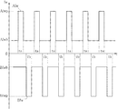
図3は、溶接装置Aによる溶接を行う際の、MIG電流AIwとTIG電流BIwを示している。本図において、縦軸は電流Iwの大きさを表し、横軸は時間tを表している。電流の符号については、MIG電極1またはTIG電極2から溶接対象材Pへと向かう方向に流れる電流を+とし、その逆の方向に流れる電流を−としている。MIG電流AIwは、常に+の値をとっており、常にMIG電極1からワイヤWを介して溶接対象材Pへと流れている。一方、TIG電流BIwは、常に−の値をとっており、常に溶接対象材PからTIG電極2へと流れている。
FIG. 3 shows the MIG current AIw and the TIG current BIw when welding by the welding apparatus A is performed. In this figure, the vertical axis represents the magnitude of current Iw, and the horizontal axis represents time t. Regarding the sign of the current, the current flowing in the direction from the
MIG電流AIwおよびTIG電流BIwは、ともにパルス波形とされている。具体的には、MIG電流AIwは、MIGベース電流値AIwbとMIGピーク電流値AIwpとを交互にとる。MIGベース電流値AIwbは、絶対値が0より大とされている。MIGピーク電流値AIwpは、絶対値がMIGベース電流値AIwbよりも大とされている。TIG電流BIwは、TIGベース電流値BIwbとTIGピーク電流値BIwpとを交互にとる。TIGベース電流値BIwbは、絶対値が0より大とされている。TIGピーク電流値BIwpは、絶対値がTIGベース電流値BIwbよりも大とされている。 Both the MIG current AIw and the TIG current BIw are pulse waveforms. Specifically, the MIG current AIw alternately takes the MIG base current value AIwb and the MIG peak current value AIwp. The MIG base current value AIwb has an absolute value greater than zero. The MIG peak current value AIwp is larger in absolute value than the MIG base current value AIwb. The TIG current BIw alternately takes a TIG base current value BIwb and a TIG peak current value BIwp. The TIG base current value BIwb has an absolute value greater than zero. The absolute value of the TIG peak current value BIwp is larger than the TIG base current value BIwb.
期間taは、MIG電流AIwがMIGピーク電流値AIwpをとる期間であり、期間tbは、TIG電流BIwがTIGピーク電流値BIwpをとる期間である。時間t軸において、期間taと期間tbとは、互いにシフトされており一致することはない。 The period ta is a period in which the MIG current AIw takes the MIG peak current value AIwp, and the period tb is the period in which the TIG current BIw takes the TIG peak current value BIwp. On the time t axis, the period ta and the period tb are shifted from each other and do not coincide with each other.
本実施形態においては、MIGベース電流値AIwbが50A程度、MIGピーク電流値AIwpが350A程度とされており、TIGベース電流値BIwbが50A程度、TIGピーク電流値BIwpが200A程度とされている。また、MIG電流AIwおよびTIG電流BIwの周波数は、120Hz以上とされており、その周期が8.3ms以下とされている。 In the present embodiment, the MIG base current value AIwb is about 50 A, the MIG peak current value AIwp is about 350 A, the TIG base current value BIwb is about 50 A, and the TIG peak current value BIwp is about 200 A. Further, the frequencies of the MIG current AIw and the TIG current BIw are 120 Hz or more, and the period is 8.3 ms or less.
次に、溶接装置Aの作用について説明する。 Next, the effect | action of the welding apparatus A is demonstrated.
本実施形態によれば、MIG電流AIwおよびTIG電流BIwは、それぞれが流れる方向が一定であるとともに、その値は0より大きい。このため、TIGアークおよびMIGアークが途切れることがない。したがって、MIG溶接およびTIG溶接を安定して行うことができる。 According to the present embodiment, the MIG current AIw and the TIG current BIw each have a constant flowing direction and a value greater than zero. For this reason, the TIG arc and the MIG arc are not interrupted. Therefore, MIG welding and TIG welding can be performed stably.
特に、MIG溶接においては、MIGアークが途切れてしまうと、その後にMIGアークを再度形成することが困難である。また、ワイヤWの先端から延びるMIGアークの長さが不安定となる。このため、MIGアークの再形成を繰り返す溶接態様は、安定した溶接に不向きである。これに対し、本実施形態においては、溶接作業中においてMIGアークが途切れることがなく、再形成が繰り返されることもない。したがって、溶接の安定化に適している。 In particular, in MIG welding, if the MIG arc is interrupted, it is difficult to form the MIG arc again thereafter. Further, the length of the MIG arc extending from the tip of the wire W becomes unstable. For this reason, the welding mode which repeats the re-formation of the MIG arc is not suitable for stable welding. On the other hand, in this embodiment, the MIG arc is not interrupted during the welding operation, and the re-formation is not repeated. Therefore, it is suitable for stabilization of welding.
また、期間taと期間tbとが互いにシフトされている。これにより、MIGアークの強さが最大となるときと、TIGアークの強さが最大となるときとはタイミングが異なる。そうすると、MIGアークとTIGアークとが互いに及ぼしあう斥力を弱めることが可能である。したがって、MIG溶接とTIG溶接とを安定して施すことが可能であり、溶接ビードが乱れることを防止することができる。 Further, the period ta and the period tb are shifted from each other. Thus, the timing is different between when the intensity of the MIG arc is maximized and when the intensity of the TIG arc is maximized. Then, the repulsive force that the MIG arc and the TIG arc exert on each other can be weakened. Therefore, MIG welding and TIG welding can be performed stably, and the weld bead can be prevented from being disturbed.
さらに、TIG電極2を常に陰極側として使用することにより、TIG電極2の先端にあるタングステン電極21が溶解することを防止できる。これにより、溶融したタングステンが溶接ビードに巻き込まれるといった不具合を回避できる。
Furthermore, it is possible to prevent the
本発明に係る溶接装置は、上述した実施形態に限定されるものではない。本発明に係る溶接装置の各部の具体的な構成は、種々に設計変更自在である。 The welding apparatus according to the present invention is not limited to the above-described embodiment. The specific configuration of each part of the welding apparatus according to the present invention can be varied in design in various ways.
本発明に係る溶接装置においては、MIG電流およびTIG電流を上述したパルス波形の電流としてそれぞれ制御可能であればよい。上記実施形態のMIG電源APSおよびTIG電源BPSは、このようなMIG電流およびTIG電流を生成可能な構成の一例であり、本発明に用いられる電流制御手段はこれに限定されない。 In the welding apparatus according to the present invention, it is only necessary that the MIG current and the TIG current can be controlled as the above-described pulse waveform currents. The MIG power source APS and the TIG power source BPS of the above embodiment are an example of a configuration capable of generating such MIG current and TIG current, and the current control means used in the present invention is not limited to this.
A 溶接装置
APS MIG電源
AIw MIG電流
AIwb ベース電流値
AIwp ピーク電流値
BPS TIG電源
BIw TIG電流
BIwb ベース電流値
BIwp ピーク電流値
W ワイヤ
G シールドガス
1 TIG電極
2 MIG電極
3 シールドノズル
21 タングステン電極
A welding apparatus APS MIG power supply AIw MIG current AIwb base current value AIwp peak current value BPS TIG power supply BIw TIG current BIwb base current value BIwp peak current value W wire
Claims (1)
TIG電極と、
上記MIG電極を介して上記ワイヤと上記溶接対象材との間に、振幅および周期を有するMIG電流を流すためのMIG電源と、
上記TIG電極と溶接対象材との間に、振幅および周期を有するTIG電流を流すためのTIG電源と、
を備える溶接装置であって、
上記MIG電流は、上記溶接対象材に対して上記ワイヤが常に陽極側となる状態で流され、かつ絶対値が0より大であるMIGベース電流値とこのMIGベース電流値よりも絶対値が大であるMIGピーク電流値とを交互にとる波形とされており、
上記TIG電流は、上記溶接対象材に対して上記TIG電極が常に陰極側となる状態で流され、かつ絶対値が0より大であるTIGベース電流値とこのTIGベース電流値よりも絶対値が大であるTIGピーク電流値とを交互にとる波形とされており、
上記MIG電流が上記MIGピーク電流値をとるときと、上記TIG電流が上記TIGピーク電流値をとるときとは、互いにシフトされていることを特徴とする、溶接装置。 A MIG electrode that holds the wire to be fed and is conductive to the wire;
A TIG electrode;
An MIG power source for passing an MIG current having an amplitude and a period between the wire and the material to be welded via the MIG electrode;
A TIG power source for flowing a TIG current having an amplitude and a period between the TIG electrode and the material to be welded;
A welding apparatus comprising:
The MIG current is flowed in a state where the wire is always on the anode side with respect to the material to be welded, and the MIG base current value having an absolute value larger than 0 and the absolute value larger than the MIG base current value. It is a waveform that alternates with the MIG peak current value,
The TIG current is flowed in a state where the TIG electrode is always on the cathode side with respect to the material to be welded, and the absolute value is larger than 0 and the absolute value is larger than the TIG base current value. It is a waveform that alternately takes a TIG peak current value that is large,
The welding apparatus, wherein the MIG current takes the MIG peak current value and the TIG current takes the TIG peak current value are shifted from each other.
Priority Applications (1)
| Application Number | Priority Date | Filing Date | Title |
|---|---|---|---|
| JP2007046455A JP2008207213A (en) | 2007-02-27 | 2007-02-27 | Welding apparatus |
Applications Claiming Priority (1)
| Application Number | Priority Date | Filing Date | Title |
|---|---|---|---|
| JP2007046455A JP2008207213A (en) | 2007-02-27 | 2007-02-27 | Welding apparatus |
Publications (2)
| Publication Number | Publication Date |
|---|---|
| JP2008207213A true JP2008207213A (en) | 2008-09-11 |
| JP2008207213A5 JP2008207213A5 (en) | 2010-02-04 |
Family
ID=39783970
Family Applications (1)
| Application Number | Title | Priority Date | Filing Date |
|---|---|---|---|
| JP2007046455A Pending JP2008207213A (en) | 2007-02-27 | 2007-02-27 | Welding apparatus |
Country Status (1)
| Country | Link |
|---|---|
| JP (1) | JP2008207213A (en) |
Cited By (4)
| Publication number | Priority date | Publication date | Assignee | Title |
|---|---|---|---|---|
| FR2963899A1 (en) * | 2010-08-17 | 2012-02-24 | Air Liquide | METHOD AND APPARATUS FOR ARC WELDING WITH MIG / MAG TORCH ASSOCIATED WITH TIG TORCH |
| CN103008835A (en) * | 2012-11-29 | 2013-04-03 | 北京工业大学 | Short circuit transition welding system of coupling arcs and control method thereof |
| US20130228555A1 (en) * | 2012-03-02 | 2013-09-05 | Lincoln Global, Inc. | Synchronized hybrid gas metal arc welding with tig/plasma welding |
| US20130299463A1 (en) * | 2010-08-05 | 2013-11-14 | Taiyo Nippon Sanso Corporation | Hybrid welding method and welding torch for hybrid welding |
Citations (4)
| Publication number | Priority date | Publication date | Assignee | Title |
|---|---|---|---|---|
| JPS5334653A (en) * | 1976-09-13 | 1978-03-31 | Kobe Steel Ltd | Arc welding |
| JPS58184069A (en) * | 1982-04-23 | 1983-10-27 | Hitachi Ltd | Multiple electrode switching welding method |
| JP2003181679A (en) * | 2001-12-13 | 2003-07-02 | Mitsubishi Heavy Ind Ltd | Method for welding, method and apparatus for removing coating material |
| JP2004001033A (en) * | 2002-05-31 | 2004-01-08 | Daihen Corp | Method for controlling two-electrode pulse arc welding |
-
2007
- 2007-02-27 JP JP2007046455A patent/JP2008207213A/en active Pending
Patent Citations (4)
| Publication number | Priority date | Publication date | Assignee | Title |
|---|---|---|---|---|
| JPS5334653A (en) * | 1976-09-13 | 1978-03-31 | Kobe Steel Ltd | Arc welding |
| JPS58184069A (en) * | 1982-04-23 | 1983-10-27 | Hitachi Ltd | Multiple electrode switching welding method |
| JP2003181679A (en) * | 2001-12-13 | 2003-07-02 | Mitsubishi Heavy Ind Ltd | Method for welding, method and apparatus for removing coating material |
| JP2004001033A (en) * | 2002-05-31 | 2004-01-08 | Daihen Corp | Method for controlling two-electrode pulse arc welding |
Cited By (8)
| Publication number | Priority date | Publication date | Assignee | Title |
|---|---|---|---|---|
| US20130299463A1 (en) * | 2010-08-05 | 2013-11-14 | Taiyo Nippon Sanso Corporation | Hybrid welding method and welding torch for hybrid welding |
| JP5589079B2 (en) * | 2010-08-05 | 2014-09-10 | 大陽日酸株式会社 | Composite welding method |
| FR2963899A1 (en) * | 2010-08-17 | 2012-02-24 | Air Liquide | METHOD AND APPARATUS FOR ARC WELDING WITH MIG / MAG TORCH ASSOCIATED WITH TIG TORCH |
| US20130228555A1 (en) * | 2012-03-02 | 2013-09-05 | Lincoln Global, Inc. | Synchronized hybrid gas metal arc welding with tig/plasma welding |
| WO2013136158A1 (en) * | 2012-03-02 | 2013-09-19 | Lincoln Global, Inc. | Synchronized hybrid gas metal arc welding with tig/plasma welding |
| CN104144762A (en) * | 2012-03-02 | 2014-11-12 | 林肯环球股份有限公司 | Synchronized hybrid gas metal arc welding with tig/plasma welding |
| US9283635B2 (en) | 2012-03-02 | 2016-03-15 | Lincoln Global, Inc. | Synchronized hybrid gas metal arc welding with TIG/plasma welding |
| CN103008835A (en) * | 2012-11-29 | 2013-04-03 | 北京工业大学 | Short circuit transition welding system of coupling arcs and control method thereof |
Similar Documents
| Publication | Publication Date | Title |
|---|---|---|
| JP3196715U (en) | Synchronous magnetic arc induction and welding | |
| JP5234042B2 (en) | Arc welding method and apparatus | |
| JP5278634B2 (en) | Arc welding control method and arc welding apparatus | |
| JP5292459B2 (en) | Method and system for increasing welding heat input during a short-circuit arc welding process | |
| JP5557238B2 (en) | AC pulse arc welding control method | |
| CN104245210B (en) | Shielded arc welding in tandem | |
| CN106607640B (en) | Welding system with reduced spatter for AC welding | |
| CN102626814A (en) | Welding device and carbon dioxide gas shielded arc welding method | |
| JP2017144480A (en) | Arc-welding method and arc-welding device | |
| JP6524412B2 (en) | Arc welding control method | |
| JP2008207213A (en) | Welding apparatus | |
| JP2011206794A (en) | Plasma mig welding method | |
| JP4890179B2 (en) | Plasma MIG welding method | |
| JP2010155251A (en) | Plasma gma welding method | |
| JP2005081387A (en) | Tig welding apparatus and method | |
| JP5154872B2 (en) | Output control method of pulse arc welding | |
| JP2010194566A (en) | Gma welding method | |
| JP5851798B2 (en) | Current control method for constriction detection in consumable electrode arc welding | |
| JP4053753B2 (en) | Multi-electrode pulse arc welding control method and welding apparatus | |
| JP2013094850A (en) | Method of controlling arc welding and apparatus for arc welding | |
| JP4342689B2 (en) | Multi-electrode pulse arc welding control method and welding apparatus | |
| JP2019072744A (en) | Mig weld method and mig weld device | |
| JP2002263838A (en) | Control method and welding equipment for multi- electrode pulse arc welding | |
| JP5926589B2 (en) | Plasma MIG welding method | |
| JP2019034333A (en) | Pulse arc welding method, method of manufacturing welding object, and welding power supply device |
Legal Events
| Date | Code | Title | Description |
|---|---|---|---|
| A521 | Written amendment |
Free format text: JAPANESE INTERMEDIATE CODE: A523 Effective date: 20091214 |
|
| A621 | Written request for application examination |
Free format text: JAPANESE INTERMEDIATE CODE: A621 Effective date: 20091214 |
|
| A977 | Report on retrieval |
Effective date: 20110908 Free format text: JAPANESE INTERMEDIATE CODE: A971007 |
|
| A131 | Notification of reasons for refusal |
Free format text: JAPANESE INTERMEDIATE CODE: A131 Effective date: 20110913 |
|
| A521 | Written amendment |
Effective date: 20111110 Free format text: JAPANESE INTERMEDIATE CODE: A523 |
|
| A02 | Decision of refusal |
Free format text: JAPANESE INTERMEDIATE CODE: A02 Effective date: 20111227 |