JP2008192524A - Cylindrical nonaqueous electrolyte solution primary battery - Google Patents
Cylindrical nonaqueous electrolyte solution primary battery Download PDFInfo
- Publication number
- JP2008192524A JP2008192524A JP2007027516A JP2007027516A JP2008192524A JP 2008192524 A JP2008192524 A JP 2008192524A JP 2007027516 A JP2007027516 A JP 2007027516A JP 2007027516 A JP2007027516 A JP 2007027516A JP 2008192524 A JP2008192524 A JP 2008192524A
- Authority
- JP
- Japan
- Prior art keywords
- electrode body
- positive electrode
- wound
- outermost
- battery
- Prior art date
- Legal status (The legal status is an assumption and is not a legal conclusion. Google has not performed a legal analysis and makes no representation as to the accuracy of the status listed.)
- Withdrawn
Links
Images

Classifications
-
- Y02E60/12—
Abstract
Description
本発明は、筒形の非水電解液一次電池に関し、更に詳しくは、高容量で安全性に優れた筒形非水電解液一次電池に関するものである。 The present invention relates to a cylindrical non-aqueous electrolyte primary battery, and more particularly to a cylindrical non-aqueous electrolyte primary battery having high capacity and excellent safety.
筒形非水電解液一次電池としては、リチウムなどを活物質とする負極と、正極とを、セパレータを介して積層したり、更にこれを巻回したりして形成された電極体を、外装缶に挿入し、電池蓋により外装缶の開口部をクリンプ封止することによって構成されたものが一般的である(例えば、特許文献1)。 As a cylindrical non-aqueous electrolyte primary battery, an electrode body formed by laminating a negative electrode using lithium or the like as an active material and a positive electrode with a separator interposed therebetween, and further winding the electrode body, In general, the battery is constructed by inserting and sealing the opening of the outer can with a battery lid (for example, Patent Document 1).
この種の電池は、負極活物質にリチウムなどを用いていることから、例えばアルカリ電解液を有する電池に比べて高エネルギー密度であり、かつ長期間の使用に適用し得ることもあって、種々の用途に用いられている。 Since this type of battery uses lithium or the like as the negative electrode active material, it has a higher energy density than, for example, a battery having an alkaline electrolyte, and may be applicable for long-term use. It is used for
また、近年の電池に対しては高容量化が強く望まれており、このような要求に応えるべく、電池蓋の周縁と外装缶の開口部の内周縁とを溶接することで封止を行う方式の電池が展開されている(例えば、特許文献2)。このような方式で封止する電池では、その内容積の多くの部分を電極体で構成することが可能となるため、高容量化も可能となる。 Further, in recent years, high capacity is strongly desired for batteries, and in order to meet such demand, sealing is performed by welding the peripheral edge of the battery lid and the inner peripheral edge of the opening of the outer can. A battery of the type has been developed (for example, Patent Document 2). In a battery that is sealed by such a method, it is possible to configure a large part of its internal volume with an electrode body, so that the capacity can be increased.
ところで、上記のような筒形非水電解液一次電池は、例えば、電池蓋には絶縁パッキングを介して端子体が取り付けられており、外装缶および電池蓋は電極体の負極と接続されて負極の電位を有し、端子体は電極体の正極と接続されて正極の電位を有するものが知られている。そして、正極については、二酸化マンガンやフッ化黒鉛を活物質に用い、その幅を負極よりも広くして、巻回構造の電極体(巻回電極体)とすることが通常であるが、このような正極は放電に伴って膨張する。その際、巻回電極体は、その径方向には外装缶によって固定されているため、正極は幅方向(電池の上方向)に膨張することとなる。 By the way, in the cylindrical non-aqueous electrolyte primary battery as described above, for example, a terminal body is attached to the battery lid through an insulating packing, and the outer can and the battery lid are connected to the negative electrode of the electrode body to form a negative electrode. It is known that the terminal body is connected to the positive electrode of the electrode body and has a positive electrode potential. For the positive electrode, it is usual to use manganese dioxide or graphite fluoride as an active material and to make the width wider than that of the negative electrode to form a wound structure electrode body (winding electrode body). Such a positive electrode expands with discharge. At that time, since the wound electrode body is fixed in the radial direction by the outer can, the positive electrode expands in the width direction (upward direction of the battery).
特許文献1に開示されているようなクリンプ封止を行った電池であれば、上記の正極の膨張をクリンプ封止部の下端部であるグルービング部で抑えることができるため、実際には、正極の膨張を小さく抑えることができる。
In the case of a battery that has been crimp-sealed as disclosed in
一方、特許文献2に開示されているような電池蓋の周縁と外装缶の開口部の内周縁とを溶接することで封止した電池では、電池の上方向への正極の膨張を抑えることができない。通常は、セパレータの幅を正極よりも広くしているため、セパレータが巻回電極体の巻回中心側に折り曲げておくことで正極の上面を覆うことができ、また、巻回電極体の上面と電池蓋との間には、絶縁板を配置しているため、膨張した正極と負極の電位を有する電池蓋との接触による短絡の発生は生じない。 On the other hand, in a battery sealed by welding the peripheral edge of the battery lid and the inner peripheral edge of the opening of the outer can as disclosed in Patent Document 2, the expansion of the positive electrode in the upward direction of the battery can be suppressed. Can not. Usually, since the separator is wider than the positive electrode, the upper surface of the positive electrode can be covered by folding the separator to the winding center side of the wound electrode body. Since an insulating plate is disposed between the battery lid and the battery lid, no short circuit occurs due to contact between the expanded positive electrode and the battery lid having the negative electrode potential.
しかし、電池作製時に巻回電極体の上面のセパレータが蛇腹状などに折れ曲がり、巻回電極体の上面を十分に覆うことができない場合には、正極の膨張によってセパレータから正極が露出し、負極の電位を有する外装缶と接触して短絡が生じる虞がある。 However, when the separator on the upper surface of the wound electrode body is bent into a bellows shape or the like when the battery is manufactured and the upper surface of the wound electrode body cannot be sufficiently covered, the positive electrode is exposed from the separator due to expansion of the positive electrode, and the negative electrode There is a possibility that a short circuit may occur due to contact with the outer can having electric potential.
また、巻回電極体の最外周にセパレータが位置する場合には、電池作製の際の巻回電極体を外装缶に挿入する工程において、巻回電極体が外装缶に接することで、セパレータに傷つきや破れが生じたり、セパレータが外側にめくれたりすることがあり、この場合、特に巻回電極体の最外周側の正極が外装缶などと接触して短絡が生じる虞もある。 Further, when the separator is located on the outermost periphery of the wound electrode body, in the step of inserting the wound electrode body into the outer can during battery production, the wound electrode body is in contact with the outer can, so that the separator The separator may be scratched or torn, or the separator may be turned outward. In this case, the positive electrode on the outermost peripheral side of the wound electrode body may come into contact with an outer can or the like to cause a short circuit.
本発明は上記事情に鑑みてなされたものであり、その目的は、高容量で安全性に優れた筒形非水電解液一次電池を提供することにある。 The present invention has been made in view of the above circumstances, and an object thereof is to provide a cylindrical non-aqueous electrolyte primary battery having a high capacity and excellent safety.
上記目的を達成し得た本発明の筒形非水電解液一次電池は、二酸化マンガンまたはフッ化黒鉛を含有する正極合剤層を集電体の両面に有する正極、リチウムまたはリチウム合金を含有する負極、およびセパレータを巻回してなり、最外周にセパレータが配置されている巻回電極体と、非水電解液とを、有底筒形の外装缶と、絶縁パッキングを介して端子体が取り付けられた電池蓋とにより形成された空間内に有する筒形非水電解液一次電池であって、上記外装缶と上記電池蓋とが溶接により封止されており、上記外装缶および上記電池蓋が負極の電位を有し、上記端子体が正極の電位を有しており、上記巻回電極体の上側の、少なくとも、上記巻回電極体側面における最外周側の正極が最外周側の負極からはみ出している部分に相当する位置の下端から、上記巻回電極体上面における最外周側の正極の集電体の位置する箇所までが、電気絶縁性のフィルムで覆われていることにより、少なくとも最外周に位置するセパレータが、上記巻回電極体の上面において、上記巻回電極体の巻回中心側に向かって折り曲げられているか、または、上記巻回電極体の下側の、少なくとも、上記巻回電極体側面における最外周側の正極が最外周側の負極からはみ出している部分に相当する位置の上端から、上記巻回電極体下面における最外周側の正極の集電体の位置する箇所までが、電気絶縁性のフィルムで覆われていることにより、少なくとも最外周に位置するセパレータが、上記巻回電極体の下面において、上記巻回電極体の巻回中心側に向かって折り曲げられていることを特徴とするものである。 The cylindrical non-aqueous electrolyte primary battery of the present invention that has achieved the above object contains a positive electrode having a positive electrode mixture layer containing manganese dioxide or graphite fluoride on both sides of the current collector, lithium, or a lithium alloy. A negative electrode and a spirally wound electrode body in which a separator is disposed on the outermost periphery and a nonaqueous electrolyte solution are attached to a terminal body via a bottomed cylindrical outer can and an insulating packing. A cylindrical non-aqueous electrolyte primary battery in a space formed by the battery lid, wherein the outer can and the battery lid are sealed by welding, and the outer can and the battery lid are The terminal body has a positive electrode potential, and the positive electrode on the outermost peripheral side at least on the side surface of the wound electrode body is above the negative electrode on the outermost peripheral side. Position corresponding to the protruding part The separator located at the outermost periphery is covered with the electrically insulating film from the lower end to the position where the current collector of the positive electrode on the outermost peripheral side on the upper surface of the wound electrode body is positioned. On the upper surface of the wound electrode body, it is bent toward the winding center side of the wound electrode body, or at least the outermost peripheral side of the side of the wound electrode body on the lower side of the wound electrode body Cover from the upper end of the position corresponding to the portion where the positive electrode protrudes from the negative electrode on the outermost peripheral side to the position where the current collector of the positive electrode on the outermost peripheral side on the lower surface of the wound electrode body is covered with an electrically insulating film. The separator located at least on the outermost periphery is bent toward the winding center side of the spirally wound electrode body on the lower surface of the spirally wound electrode body. That.
電池の放電に伴う正極の膨張に起因する短絡は、主に巻回電極体の最外周側の正極の膨張によって生じる。本発明の筒形非水電解液一次電池では、巻回電極体の上側において上記のように電気絶縁性のフィルムを配置して、巻回電極体の少なくとも最外周に位置するセパレータを、巻回電極体の上面において巻回電極体の巻回中心側に向かって折り曲げており、これにより、巻回電極体の最外周側の正極の上面部分をセパレータで確実に覆うことができるため、巻回電極体の最外周側の正極の膨張に起因する短絡の発生を防止して、安全性を高めることができる。 The short circuit caused by the expansion of the positive electrode accompanying the discharge of the battery is mainly caused by the expansion of the positive electrode on the outermost peripheral side of the wound electrode body. In the cylindrical non-aqueous electrolyte primary battery of the present invention, an electrically insulating film is arranged on the upper side of the wound electrode body as described above, and a separator located at least on the outermost periphery of the wound electrode body is wound. Since the upper surface of the electrode body is bent toward the winding center side of the wound electrode body, and the upper surface portion of the positive electrode on the outermost peripheral side of the wound electrode body can be reliably covered with the separator, The occurrence of a short circuit due to expansion of the positive electrode on the outermost peripheral side of the electrode body can be prevented, and safety can be improved.
また、本発明の筒形非水電解液一次電池では、巻回電極体の下側において上記のように電気絶縁性のフィルムを配置して、巻回電極体の少なくとも最外周に位置するセパレータを、巻回電極体の下面において巻回電極体の巻回中心側に向かって折り曲げることにより、巻回電極体を外装缶に挿入する際に、巻回電極体の最外周に位置するセパレータの巻回電極体下側の箇所と外装缶との接触を防止して、セパレータの傷つきや破れ、外側へのめくれを抑制することができるため、かかるセパレータの傷つきや破れ、外側へのめくれに起因する短絡の発生を防止して、安全性を高めることができる。 In the cylindrical non-aqueous electrolyte primary battery of the present invention, an electrically insulating film is disposed on the lower side of the wound electrode body as described above, and a separator located at least on the outermost periphery of the wound electrode body is provided. The separator electrode located on the outermost periphery of the wound electrode body is bent when the wound electrode body is inserted into the outer can by bending the lower surface of the wound electrode body toward the winding center side of the wound electrode body. The contact between the lower part of the rotating electrode body and the outer can can be prevented, and the separator can be prevented from being damaged or torn and turned to the outside. The occurrence of a short circuit can be prevented and safety can be improved.
更に、複数の筒形非水電解液一次電池を使用する機器において、そのうちの一部の電池を逆接続したり、他に主電源を持つ機器のバックアップ用電源などとして筒形非水電解液一次電池を使用した際に主電源から漏れ電流が生じたりすることで、筒形非水電解液一次電池が充電されてしまった場合には、負極の電位を有する箇所(例えば外装缶)にLi(リチウム)が析出してデンドライトが生じ、これが正極(特に巻回電極体の最外周側の正極のうち、最外周の負極からはみ出した部分)と接触することによっても短絡が生じることがある。しかし、本発明の筒形非水電解液一次電池では、巻回電極体側面の上端または下端に電気絶縁性のフィルムを配置しているため、上記のようなリチウムデンドライトによる短絡の発生も防止して、安全性を高めることができる。 Furthermore, in equipment that uses multiple tubular nonaqueous electrolyte primary batteries, some of the batteries can be reversely connected, or the tubular nonaqueous electrolyte primary can be used as a backup power source for equipment with other main power supplies. When a cylindrical non-aqueous electrolyte primary battery has been charged due to leakage current from the main power supply when the battery is used, Li ( Lithium is precipitated and dendrites are generated, and a short circuit may occur also when this contacts with the positive electrode (particularly, the portion of the positive electrode on the outermost peripheral side of the wound electrode body that protrudes from the negative electrode on the outermost periphery). However, in the cylindrical non-aqueous electrolyte primary battery of the present invention, since an electrically insulating film is disposed on the upper end or lower end of the side surface of the wound electrode body, occurrence of a short circuit due to the lithium dendrite as described above is prevented. Therefore, safety can be improved.
また、本発明の筒形非水電解液一次電池では、外装缶と電池蓋とが溶接により封止される構成とすることで、電池の内容積のうち巻回電極体を収容可能な部分の容積を大きくして、高容量化を達成することもできる。 Moreover, in the cylindrical non-aqueous electrolyte primary battery of the present invention, the outer can and the battery lid are sealed by welding, so that the portion of the internal volume of the battery that can accommodate the wound electrode body The capacity can be increased by increasing the volume.
なお、本発明に係る「電気絶縁性のフィルム」とは、絶縁抵抗が100MΩ以上となるような抵抗特性を有するフィルムを意味している。 The “electrically insulating film” according to the present invention means a film having resistance characteristics such that the insulation resistance is 100 MΩ or more.
本発明によれば、高容量で安全性に優れた筒形非水電解液一次電池を提供できる。 According to the present invention, it is possible to provide a cylindrical non-aqueous electrolyte primary battery having high capacity and excellent safety.
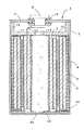
図1に、本発明の筒形非水電解液一次電池の一例を表す縦断側面図を示す。図1において、筒形非水電解液一次電池1は、上方開口部を有する有底円筒状の外装缶2と、外装缶2内に装填された正極4と負極5とをセパレータ6を介して巻回してなる巻回電極体3と、非水電解液(以下、単に「電解液」という場合がある)と、外装缶2の上方開口部を封止する電池蓋7を有している。言い換えれば、図1の筒形非水電解液一次電池1は、外装缶2と外装缶2の上方開口部を封止する電池蓋7とで囲まれる空間内に、正極4と負極5とをセパレータ6を介して巻回してなる巻回電極体3や電解液といった発電要素を有するものである。外装缶2は、鉄(好ましくは、Niメッキなどのメッキを施した鉄板)やステンレス鋼などを素材とし、外装缶2の形状としては、円筒形や角筒形などの筒形が挙げられる。
FIG. 1 is a longitudinal side view showing an example of the cylindrical non-aqueous electrolyte primary battery of the present invention. In FIG. 1, a cylindrical non-aqueous electrolyte
外装缶2の上方開口部には電池蓋7が配されており、電池蓋7は、外装缶2の上方開口部の内周縁に溶接されることにより、外装缶2と電池蓋7とで密閉空間を形成している。本発明の電池ではこのような封止構造を採用することで、電池の内容積のうち巻回電極体を収容可能な部分の容積を大きくして、高容量化を達成している。外装缶と電池蓋との溶接は、例えばレーザー溶接法により行うことが好ましい。 A battery lid 7 is disposed in the upper opening of the outer can 2, and the battery lid 7 is sealed between the outer can 2 and the battery lid 7 by being welded to the inner periphery of the upper opening of the outer can 2. A space is formed. In the battery of the present invention, by adopting such a sealing structure, the volume of the portion that can accommodate the wound electrode body in the internal volume of the battery is increased to achieve high capacity. The welding between the outer can and the battery lid is preferably performed by a laser welding method, for example.
電池蓋7には、その中央部に開設された開口に、ポリプロピレンなどのポリオレフィンなどを素材とする絶縁パッキング8を介して装着された端子体9が設置されている。また、電池蓋7の下部にはポリプロピレンなどのポリオレフィンなどを素材とする絶縁板10が配置されており、該絶縁板10は、円盤状のベース部11の周縁に環状の側壁12を立設した上向きに開口する丸皿形状に形成されていて、ベース部11の中央にはガス通口13が開設されている。
The battery lid 7 is provided with a terminal body 9 mounted in an opening formed in the center thereof via an insulating packing 8 made of polyolefin such as polypropylene. Further, an
電池内圧が急激に上昇したときの対策として、電池蓋7または外装缶2の缶底2aには、薄肉部(ベント)を設けることができる。正極4と端子体9の下面とは、正極リード体14で接続されており、端子体9は正極の電位を有している。また、負極5に取り付けられた負極リード体15は、外装缶2の缶底2a内面に溶接されており、外装缶2および電池蓋7は負極の電位を有している。
As a countermeasure when the battery internal pressure suddenly increases, a thin wall portion (vent) can be provided on the battery lid 7 or the
図2に、本発明の電池に係る巻回電極体3の一例の断面要部拡大図を示す。図2に示すように、巻回電極体3に係る正極4は、正極集電体41の両面に、正極活物質を含む正極合剤層40、41が形成されることで構成されている。そして、巻回電極体3では、その上側の、巻回電極体3側面における最外周側の正極4が最外周側の負極5からはみ出している部分に相当する位置の下端(図中A)から、巻回電極体3上面における最外周側の正極4の集電体41の位置する箇所(図中B)までを含む部分が、電気絶縁性のフィルム16で覆われており、これにより、少なくとも最外周に位置するセパレータ6が、巻回電極体3の上面において、巻回電極体3の巻回中心側に向かって折り曲げられている。このような構造の巻回電極体3を用いることにより、電池の放電に伴って生じる正極の膨張に起因する短絡の発生を抑制することができ、また、電池が充電されてしまうことでリチウムデンドライトが析出した場合に生じ得る短絡の発生も抑制することができる。
In FIG. 2, the cross-sectional principal part enlarged view of an example of the
また、図2に示す巻回電極体3では、その下側の、巻回電極体3側面における最外周側の正極4が最外周側の負極5からはみ出している部分に相当する位置の上端(図中C)から、巻回電極体3下面における最外周側の正極4の集電体41の位置する箇所(図中D)までを含む部分が、電気絶縁性のフィルム16で覆われており、これにより、少なくとも最外周に位置するセパレータ6が、巻回電極体3の下面において、巻回電極体3の巻回中心側に向かって折り曲げられている。このような構造の巻回電極体3を用いることにより、電池製造時に生じ得る巻回電極体最外周に位置するセパレータの傷つきや破れ、外側へのめくれを防止して、短絡の発生を抑制することができ、また、電池が充電されてしまうことでリチウムデンドライトが析出した場合に生じ得る短絡の発生も抑制することができる。
Further, in the spirally
本発明の電池では、電気絶縁性フィルムを上記のように配置することで、少なくとも最外周のセパレータが、巻回電極体の上面または下面のいずれかにおいて、巻回電極体の巻回中心側に向かって折り曲げられていればよいが、図2に示すように、巻回電極体の上面と下面との両方において、少なくとも最外周のセパレータが巻回電極体の巻回中心側に向かって折り曲げられていることが好ましく、この場合には、より安全性に優れた電池とすることができる。 In the battery of the present invention, by disposing the electrically insulating film as described above, at least the outermost separator is on the winding center side of the wound electrode body on either the upper surface or the lower surface of the wound electrode body. As shown in FIG. 2, at least the outermost separator is bent toward the winding center side of the wound electrode body on both the upper surface and the lower surface of the wound electrode body. In this case, the battery can be more excellent in safety.
また、巻回電極体の上面においては、電気絶縁性のフィルムは、少なくとも、巻回電極体側面における最外周側の正極が最外周側の負極からはみ出している部分に相当する位置の下端から、巻回電極体上面における最外周側の正極の集電体の位置する箇所までを覆っていればよいが、例えば、巻回電極体上面における最外周側の正極の集電体の位置する箇所を超えて、更に巻回中心側の部分も覆っていてもよいし、図2に示すように、巻回電極体側面における最外周側の正極が最外周側の負極からはみ出している部分に相当する位置の下端よりも下側まで覆っていてもよい。よって、巻回電極体上面においては、最外周のセパレータ以外のセパレータ(例えば、図2に示すように最外周側のセパレータよりも1周内側のセパレータ)も、電気絶縁性のフィルムによって巻回電極体の巻回中心側に向かって折り曲げられていてもよい。 Further, on the upper surface of the wound electrode body, the electrically insulating film is at least from the lower end of the position corresponding to the portion where the positive electrode on the outermost peripheral side of the side surface of the wound electrode body protrudes from the negative electrode on the outermost peripheral side, It is only necessary to cover the position of the outermost positive electrode current collector on the upper surface of the wound electrode body, for example, the position of the outermost positive electrode current collector on the upper surface of the wound electrode body In addition, the winding center side portion may be covered, and as shown in FIG. 2, the outermost positive electrode on the side surface of the winding electrode body corresponds to a portion protruding from the outermost negative electrode. You may cover to the lower side rather than the lower end of a position. Therefore, on the upper surface of the wound electrode body, a separator other than the outermost separator (for example, a separator on the inner side of the outermost separator as shown in FIG. 2) is also wound by an electrically insulating film. It may be bent toward the winding center side of the body.
加えて、巻回電極体の下面においては、電気絶縁性のフィルムは、少なくとも、巻回電極体側面における最外周側の正極が最外周側の負極からはみ出している部分に相当する位置の上端から、巻回電極体下面における最外周側の正極の集電体の位置する箇所までを覆っていればよいが、例えば、巻回電極体下面における最外周側の正極の集電体の位置する箇所を超えて、更に巻回中心側の部分も覆っていてもよいし、図2に示すように、巻回電極体側面における最外周側の正極が最外周側の負極からはみ出している部分に相当する位置の上端よりも上側まで覆っていてもよい。よって、巻回電極体下面においては、最外周のセパレータ以外のセパレータ(例えば、図2に示すように最外周側のセパレータよりも1周内側のセパレータ)も、電気絶縁性のフィルムによって巻回電極体の巻回中心側に向かって折り曲げられていてもよい。 In addition, on the lower surface of the wound electrode body, the electrically insulating film is at least from the upper end of the position corresponding to the portion where the positive electrode on the outermost peripheral side of the side surface of the wound electrode body protrudes from the negative electrode on the outermost peripheral side. The outermost positive electrode current collector on the lower surface of the wound electrode body only needs to be covered, for example, the outermost positive electrode current collector on the lower surface of the wound electrode body is located. Further, the winding center side portion may be covered, and as shown in FIG. 2, the outermost positive electrode on the side surface of the wound electrode body corresponds to the portion protruding from the outermost negative electrode. You may cover to the upper side rather than the upper end of the position to do. Therefore, on the lower surface of the wound electrode body, a separator other than the outermost separator (for example, a separator on the inner side of the outermost separator as shown in FIG. 2) is also wound by an electrically insulating film. It may be bent toward the winding center side of the body.
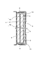
図3には、本発明の電池に係る巻回電極体3の他の例の断面要部拡大図を示している。図3に示す巻回電極体3では、その側面全面が電気絶縁性のフィルム16で覆われている(すなわち、巻回電極体の上面における最外周側の正極の集電体の位置する箇所から、巻回電極体側面全面を含み、巻回電極体の下面における最外周側の正極の集電体の位置する箇所までが、電気絶縁性のフィルムで覆われている)。このような構造の巻回電極体3であれば、1枚の電気絶縁性のフィルム16で巻回電極体の上面および下面の所定箇所までを覆うことができるため、巻回電極体3の生産性、ひいては筒形非水電解液一次電池の生産性を高めることができる。また、図3に示す構造の巻回電極体を用いることで、巻回電極体を外装缶に挿入する際の最外周のセパレータの傷つきや破れ、外側へのめくれをより良好に防止でき、更に、リチウムデンドライトが発生した場合の短絡の発生もより良好に抑制することができる。
In FIG. 3, the cross-sectional principal part enlarged view of the other example of the
また、電気絶縁性のフィルムにより巻回電極体の巻回中心側に向かって折り曲げられたセパレータは、電気絶縁性のフィルムと同様に、巻回電極体の上面および下面における最外周側の正極の集電体の位置する箇所を超えていることが好ましく、巻回電極体の上面および下面における最外周側の正極全てを覆っていることがより好ましい。 In addition, the separator bent by the electrically insulating film toward the winding center side of the wound electrode body is similar to the electrically insulating film in the positive electrode on the outermost peripheral side on the upper and lower surfaces of the wound electrode body. It is preferable to exceed the position where the current collector is located, and it is more preferable to cover all of the positive electrodes on the outermost peripheral side of the upper and lower surfaces of the wound electrode body.
次に、本発明の非水電解液一次電池の各構成の詳細を説明する。 Next, the detail of each structure of the nonaqueous electrolyte primary battery of this invention is demonstrated.
<正極>
正極としては、例えば、正極活物質に、導電助剤やバインダを配合し、必要に応じて水などを添加してなる正極合剤(スラリー)を、ロールなどを用いて圧延するなどして予備シート化し、これを乾燥・粉砕したものを再度ロール圧延などしてシート形状に成形したものを、集電体の片面または両面に重ね、プレスなどにより正極合剤シートと集電体とを一体化して、集電体の片面または両面に正極合剤シートからなる層(正極合剤層)を形成したものが使用できる。
<Positive electrode>
As the positive electrode, for example, a positive electrode mixture (slurry) obtained by blending a positive electrode active material with a conductive additive or a binder and adding water or the like as necessary is preliminarily rolled by using a roll or the like. Sheeted, dried and pulverized, and rolled into a sheet shape again, etc., stacked on one or both sides of the current collector, and the positive electrode mixture sheet and current collector are integrated by pressing or the like And what formed the layer (positive electrode mixture layer) which consists of a positive mix sheet on the single side | surface or both surfaces of a collector can be used.
具体的には、例えば、集電体が、2枚の正極合剤シートよりも数mm内側にくるようにして三者を重ね合わせ、巻回始端部となる長さ方向の端部から3〜10mmの部分をプレスすることでシート状正極を製造できる。なお、作業上の観点からは、巻回電極体の作製に先立って、2枚の正極合剤シートと正極集電体とを一体化しておくことが好ましいが、独立した2枚の正極合剤シートとを、巻回電極体の巻回時に一体化しても構わず、このような製法によっても特性上は特に問題はない。 Specifically, for example, the current collector is overlapped by 3 mm so that the current collector is located several mm inside the two positive electrode mixture sheets, and 3 to 3 from the end in the length direction that becomes the winding start end. A sheet-like positive electrode can be produced by pressing a 10 mm portion. From the viewpoint of work, it is preferable that the two positive electrode mixture sheets and the positive electrode current collector are integrated prior to the production of the wound electrode body. The sheet may be integrated at the time of winding the wound electrode body, and there is no particular problem in terms of characteristics even by such a manufacturing method.
なお、本発明に係る正極は、上記の製法により製造されたものに限定されず、他の製法により製造されたものであってもよい。例えば、正極合剤スラリーを集電体の片面または両面に塗布して乾燥し、必要に応じてプレス処理などを施して集電体上に正極合剤層を形成する製法により製造された正極でもよい。 In addition, the positive electrode which concerns on this invention is not limited to what was manufactured by said manufacturing method, The thing manufactured by the other manufacturing method may be used. For example, even a positive electrode manufactured by a manufacturing method in which a positive electrode mixture slurry is applied to one or both sides of a current collector and dried, and subjected to a press treatment as necessary to form a positive electrode mixture layer on the current collector. Good.
正極活物質としては、二酸化マンガンまたはフッ化黒鉛が用いられる。導電助剤としては、例えば、黒鉛、カーボンブラック(ケッチェンブラックなど)、アセチレンブラックなどが挙げられ、これらを1種単独で用いる他、2種以上を併用してもよい。バインダとしては、ポリテトラフルオロエチレン(PTFE)、ポリフッ化ビニリデン(PVDF)などのフッ素樹脂;ゴム系バインダ;などが使用できる。なお、PTFE、PVDFなどのフッ素樹脂の場合、ディスパージョンタイプのものでもよいし、粉末状のものでもよいが、ディスパージョンタイプのものが特に好適である。 As the positive electrode active material, manganese dioxide or graphite fluoride is used. Examples of the conductive assistant include graphite, carbon black (such as Ketjen black), and acetylene black. These may be used alone or in combination of two or more. As the binder, fluorine resins such as polytetrafluoroethylene (PTFE) and polyvinylidene fluoride (PVDF); rubber binders, and the like can be used. In the case of a fluororesin such as PTFE or PVDF, a dispersion type or a powder type may be used, but a dispersion type is particularly preferable.
正極に係る正極合剤層においては、例えば、正極活物質の含有量を92〜97質量%、導電助剤の含有量を2〜4質量%、およびバインダの含有量を1〜4質量%とすることが好ましい。また、正極合剤層の厚み(集電体の両面に形成されている場合は、片面当たりの厚み)は、例えば、50〜1500μmであることが好ましい。 In the positive electrode mixture layer according to the positive electrode, for example, the content of the positive electrode active material is 92 to 97% by mass, the content of the conductive additive is 2 to 4% by mass, and the content of the binder is 1 to 4% by mass. It is preferable to do. In addition, the thickness of the positive electrode mixture layer (when formed on both sides of the current collector, the thickness per side) is preferably, for example, 50 to 1500 μm.
正極に係る正極合剤層の密度は、例えば、2.1〜2.8g/cm3であることが好ましい。なお、本明細書でいう正極合剤層の密度は、乾燥状態の正極合剤層の体積と重量によって求められる値である。 The density of the positive electrode mixture layer relating to the positive electrode is preferably, for example, 2.1 to 2.8 g / cm 3 . The density of the positive electrode mixture layer in the present specification is a value determined by the volume and weight of the positive electrode mixture layer in a dry state.
非水電解液一次電池の負荷特性(特に中負荷での放電特性)を向上させる観点からは、導電助剤に、BET比表面積が400〜2000m2/gのカーボンブラック(特にケッチェンブラック)を用い、正極合剤層における上記導電助剤の含有量を2.0〜4.0質量%とし、更に正極合剤層の密度を2.2〜2.7g/cm3とすることがより好ましい。 From the viewpoint of improving the load characteristics of the non-aqueous electrolyte primary battery (especially the discharge characteristics at medium load), carbon black (particularly ketjen black) having a BET specific surface area of 400 to 2000 m 2 / g is used as a conductive additive. More preferably, the content of the conductive additive in the positive electrode mixture layer is 2.0 to 4.0% by mass, and the density of the positive electrode mixture layer is 2.2 to 2.7 g / cm 3. .
なお、本明細書でいう導電助剤のBET比表面積は、多分子吸着の理論式であるBET式を用いて、表面積を測定、計算したもので、活物質の表面と微細孔の比表面積である。また、後記の実施例におけるカーボンブラックのBET比表面積の測定には、窒素吸着法による比表面積測定装置(Mountech社製「Macsorb HM model−1201」)を用いた。 In addition, the BET specific surface area of the conductive assistant referred to in this specification is a surface area measured and calculated using the BET formula which is a theoretical formula of multimolecular adsorption. is there. Moreover, the specific surface area measuring apparatus by the nitrogen adsorption method ("Macsorb HM model-1201" by Mounttech) was used for the measurement of the BET specific surface area of carbon black in the Example mentioned later.
正極に用いる集電体としては、例えば、SUS316、SUS430、SUS444などのステンレス鋼を素材とするものが挙げられ、その形態としては、平織り金網、エキスパンドメタル、ラス網、パンチングメタル、箔(板)などが例示できる。集電体の厚みは、例えば、0.1〜0.4mmであることが好ましい。 Examples of the current collector used for the positive electrode include those made of stainless steel such as SUS316, SUS430, and SUS444, and the forms thereof include plain weave metal mesh, expanded metal, lath net, punching metal, and foil (plate). Etc. can be exemplified. The thickness of the current collector is preferably, for example, 0.1 to 0.4 mm.
正極集電体の表面には、ペースト状の導電材を塗布しておくことが望ましい。正極集電体として立体構造を有する網状のものを用いた場合も、金属箔やパンチングメタルなどの本質的に平板からなる材料を用いた場合と同様に、導電材の塗布により集電効果の著しい改善が認められる。これは、網状の集電体の金属部分が正極合剤層と直接的に接触する経路のみならず、網目内に充填された導電材を介しての経路が有効に利用されていることによるものと推定される。 It is desirable to apply a paste-like conductive material to the surface of the positive electrode current collector. When a positive electrode current collector having a three-dimensional structure is used, as in the case of using an essentially flat material such as a metal foil or a punching metal, the current collecting effect is remarkable by applying a conductive material. Improvement is observed. This is because not only the route in which the metal part of the mesh current collector is in direct contact with the positive electrode mixture layer but also the route through the conductive material filled in the mesh is effectively used. It is estimated to be.
導電材としては、例えば、銀ペーストやカーボンペーストなどを用いることができる。特にカーボンペーストは、銀ペーストに比べて材料費が安く済み、しかも銀ペーストと略同等の接触効果が得られるため、非水電解液一次電池の製造コストの低減化を図る上で好適である。導電材のバインダとしては、水ガラスやイミド系のバインダなどの耐熱性の材料を用いることが好ましい。これは正極合剤層中の水分を除去する際に200℃を超える高温で乾燥処理するためである。 As the conductive material, for example, silver paste or carbon paste can be used. In particular, the carbon paste is suitable for reducing the manufacturing cost of the non-aqueous electrolyte primary battery because the material cost is lower than that of the silver paste and the contact effect is almost the same as that of the silver paste. As the binder for the conductive material, it is preferable to use a heat resistant material such as water glass or an imide binder. This is because the drying process is performed at a high temperature exceeding 200 ° C. when moisture in the positive electrode mixture layer is removed.
<負極>
負極としては、図1に示すようなシート状負極が挙げられ、このシート状負極は、例えば、負極活物質である金属リチウム箔と、負極集電体である金属箔とで構成することができる。また、金属リチウム箔のみで負極を構成してもよい。金属リチウム箔の材料としては金属リチウムのみならず、リチウム−アルミニウムなどのリチウム合金を挙げることができる。金属リチウム箔の厚みとしては、例えば、0.15〜0.4mmであることが好ましい。
<Negative electrode>
Examples of the negative electrode include a sheet-like negative electrode as shown in FIG. 1, and the sheet-like negative electrode can be composed of, for example, a metal lithium foil that is a negative electrode active material and a metal foil that is a negative electrode current collector. . Moreover, you may comprise a negative electrode only with metal lithium foil. Examples of the material for the metal lithium foil include not only metal lithium but also lithium alloys such as lithium-aluminum. The thickness of the metal lithium foil is preferably 0.15 to 0.4 mm, for example.
負極集電体の素材としては、銅、ニッケル、鉄、ステンレスなどを挙げることができる。負極集電体の厚み分だけ外装缶の内部体積が減少するため、負極集電体の厚み寸法は可及的に小さいことが好ましく、具体的には、例えば、0.1mm以下とすることが推奨される。すなわち、負極集電体が厚すぎると、負極活物質である金属リチウム箔などの仕込み量を少なくせざるを得ず、電池容量の低下を招く虞がある。また、負極集電体が薄すぎると、破れやすくなるため、負極集電体の厚みは、0.005mm以上とすることが望ましい。また、負極集電体は、その幅が金属リチウム箔の幅と同じか、それよりも広いことが好ましく、また、その面積が片面に配置される金属リチウム箔の面積の100〜130%であることが好ましい。負極集電体の面積を上記のようにすることによって、負極集電体の幅が金属リチウム箔の幅と同じかまたは広く、長さが長くなるため、負極集電体の周囲に沿って金属リチウム箔が切れて電気的接続が断たれることを防ぐことができる。 Examples of the material for the negative electrode current collector include copper, nickel, iron, and stainless steel. Since the internal volume of the outer can decreases by the thickness of the negative electrode current collector, the thickness dimension of the negative electrode current collector is preferably as small as possible, specifically, for example, 0.1 mm or less. Recommended. That is, if the negative electrode current collector is too thick, the amount of metal lithium foil or the like that is the negative electrode active material must be reduced, which may lead to a decrease in battery capacity. Moreover, since it will be easy to tear when a negative electrode collector is too thin, it is desirable that the thickness of a negative electrode collector be 0.005 mm or more. The width of the negative electrode current collector is preferably the same as or wider than the width of the metal lithium foil, and the area is 100 to 130% of the area of the metal lithium foil arranged on one side. It is preferable. By making the area of the negative electrode current collector as described above, the width of the negative electrode current collector is the same as or wider than the width of the metal lithium foil, and the length becomes longer. It is possible to prevent the lithium foil from being cut and the electrical connection from being cut off.
<電解液>
本発明の筒形非水電解液一次電池に係る電解液としては、有機溶媒などの非水系溶媒に電解質としてLiPF6、LiClO4、LiCF3SO3などを溶解して調製したものが挙げられる。その溶媒としてはエチレンカーボネート、プロピレンカーボネートなどの環状エステルにジメトキシエタンなどの鎖状エーテル、ジメチルカーボネートなどの鎖状エステルを混合したものが例示できる。電解液中の電解質の濃度としては0.3〜1.5mol/lが好ましい。
<Electrolyte>
Examples of the electrolyte solution according to the cylindrical non-aqueous electrolyte primary battery of the present invention include those prepared by dissolving LiPF 6 , LiClO 4 , LiCF 3 SO 3, etc. as an electrolyte in a non-aqueous solvent such as an organic solvent. Examples of the solvent include a mixture of a cyclic ester such as ethylene carbonate and propylene carbonate with a chain ether such as dimethoxyethane and a chain ester such as dimethyl carbonate. The concentration of the electrolyte in the electrolytic solution is preferably 0.3 to 1.5 mol / l.
<電気絶縁性のフィルム>
電気絶縁性のフィルムの素材としては、電気絶縁性を有しており、電池内において分解したり電解液に溶解したりせず、安定にフィルム形状を保ち得る樹脂であれば特に制限はないが、PE、PPなどのポリオレフィンが好ましい。電気絶縁性のフィルムは、内部に孔を有しないものでもよく、孔を有するものでもよいが、孔を有する場合には、その空孔率は10%以下であることが好ましい。
<Electrically insulating film>
The material of the electrically insulating film is not particularly limited as long as it has electrical insulating properties and does not decompose in the battery or dissolve in the electrolyte solution and can stably maintain the film shape. Polyolefins such as PE, PP are preferred. The electrically insulating film may have no pores or may have pores therein, but in the case of having pores, the porosity is preferably 10% or less.
電気絶縁性のフィルムの厚みは、その機能をより有効に発揮させる観点から、10μm以上であることが好ましく、20μm以上であることがより好ましい。ただし、電気絶縁性のフィルムをあまり厚くしても、その効果が飽和し、却って電池内での電気絶縁性フィルムの占有体積が増大してしまうため、その厚みは、100μm以下であることが好ましく、50μm以下であることがより好ましい。 The thickness of the electrically insulating film is preferably 10 μm or more and more preferably 20 μm or more from the viewpoint of more effectively exerting its function. However, even if the electrically insulating film is made too thick, the effect is saturated, and on the contrary, the occupied volume of the electrically insulating film in the battery increases. Therefore, the thickness is preferably 100 μm or less. More preferably, it is 50 μm or less.
<セパレータ>
セパレータとしては、従来公知の非水電解液一次電池に採用されている微孔性フィルム製のセパレータや不織布製のセパレータが適用できる。
<Separator>
As a separator, the separator made from a microporous film and the separator made from a nonwoven fabric which are employ | adopted as a conventionally well-known nonaqueous electrolyte primary battery are applicable.
セパレータとなる微孔性フィルムを構成する樹脂としては、例えば、ポリエチレン(PE)、ポリプロピレン(PP)などのポリオレフィンなどが挙げられる。このような微孔性フィルムの市販品としては、例えば、旭化成株式会社製「ハイポア」(商品名)、東燃化学社製「セティーラ」(商品名)などが挙げられる。 As resin which comprises the microporous film used as a separator, polyolefin, such as polyethylene (PE) and polypropylene (PP), etc. are mentioned, for example. Examples of such commercially available microporous films include “Hypore” (trade name) manufactured by Asahi Kasei Corporation, “Setilla” (trade name) manufactured by Tonen Chemical Co., Ltd., and the like.
また、セパレータとなる不織布としては、例えば、ポリエチレン(PE)、ポリプロピレン(PP)などのポリオレフィンなどを素材とし、公知の各種製法で製造されたものを用いることができる。 Moreover, as a nonwoven fabric used as a separator, what was manufactured by various well-known manufacturing methods can be used, for example, using polyolefins, such as polyethylene (PE) and polypropylene (PP).
更に、上記微孔性フィルムと上記不織布とを積層した構造のセパレータを用いてもよい。 Furthermore, you may use the separator of the structure which laminated | stacked the said microporous film and the said nonwoven fabric.
セパレータの厚みは、例えば、好ましくは10μm以上、より好ましくは20μm以上であって、好ましくは100μm以下、より好ましくは50μm以下である。また、セパレータの空孔率は、例えば、好ましくは20%以上、より好ましくは30%以上であって、好ましくは60%以下、より好ましくは50%以下である。 The thickness of the separator is, for example, preferably 10 μm or more, more preferably 20 μm or more, preferably 100 μm or less, more preferably 50 μm or less. Further, the porosity of the separator is, for example, preferably 20% or more, more preferably 30% or more, preferably 60% or less, more preferably 50% or less.
なお、本発明の筒形非水電解液一次電池を説明するに当たり、図1〜図3を参照したが、これらの図面は、本発明の電池の一例を示すものに過ぎず、本発明の電池はこれらの図面に図示したものに限定される訳ではない。また、図1〜図3は、本発明の電池の構成を説明するためのものであって、そのサイズなどは必ずしも正確ではない。 In describing the cylindrical non-aqueous electrolyte primary battery of the present invention, FIGS. 1 to 3 were referred to. However, these drawings are only examples of the battery of the present invention, and the battery of the present invention. Is not limited to those illustrated in these drawings. Moreover, FIGS. 1-3 is for demonstrating the structure of the battery of this invention, Comprising: The size etc. are not necessarily exact.
本発明の筒形非水電解液一次電池は、安全性に優れており、しかも容量が大きいため、このような特性を生かして、住宅用火災警報器の電源用途や、ガス、電気、水道などの各種メーターの電源用途などを始めとして、従来公知の筒形非水電解液一次電池が適用されている各種用途に適用することができる。 The cylindrical non-aqueous electrolyte primary battery of the present invention is excellent in safety and has a large capacity. Therefore, taking advantage of such characteristics, it can be used as a power source for residential fire alarms, gas, electricity, water, etc. It can be applied to various uses to which a conventionally known cylindrical non-aqueous electrolyte primary battery is applied, including the power supply use of various meters.
以下、実施例に基づいて本発明を詳細に述べる。ただし、下記実施例は、本発明を制限するものではなく、前・後記の趣旨を逸脱しない範囲で変更実施をすることは、全て本発明の技術的範囲に包含される。この実施例においては、筒形非水電解液一次電池として、外径:17mm、高さ:45mmの円筒形非水電解液一次電池を例に挙げて説明する。なお、本実施例で使用する「%」は、特に断らない限り質量基準(質量%)である。 Hereinafter, the present invention will be described in detail based on examples. However, the following examples are not intended to limit the present invention, and all modifications made without departing from the spirit of the preceding and following descriptions are included in the technical scope of the present invention. In this embodiment, a cylindrical nonaqueous electrolyte primary battery having an outer diameter of 17 mm and a height of 45 mm will be described as an example of a cylindrical nonaqueous electrolyte primary battery. In addition, "%" used in a present Example is a mass reference | standard (mass%) unless there is particular notice.
実施例1
実施例1の筒形非水電解液一次電池について、[正極の作製]、[負極の作製]、[巻回電極体の作製]、[電池組み立て]、[後処理(予備放電、エージング)]の順に説明する。
Example 1
For the cylindrical nonaqueous electrolyte primary battery of Example 1, [Preparation of positive electrode], [Preparation of negative electrode], [Preparation of wound electrode body], [Assembly of battery], [Post-treatment (preliminary discharge, aging)] Will be described in the order.
[正極の作製]
まず、以下の手順で、正極合剤(質量比で、固形分:水分=100:30のもの)を調製した。BET比表面積が1000m2/gのカーボンブラック:3%と二酸化マンガン(東ソー社製):92%とを、プラネタリーミキサーを用いて乾式で5分間混合した後、水を固形分の20%(質量比)となるように添加して5分間混合した。PTFEディスパージョン(ダイキン工業社製「D−1」)を、固形分が、正極合剤の固形分で5%に当たる量だけ用意し、これを残りの水で希釈して、上記の混合物に添加し、5分間混合して正極合剤を得た。
[Production of positive electrode]
First, a positive electrode mixture (in mass ratio, solid content: water content = 100: 30) was prepared by the following procedure. Carbon black having a BET specific surface area of 1000 m 2 / g: 3% and manganese dioxide (manufactured by Tosoh Corporation): 92% were mixed for 5 minutes in a dry manner using a planetary mixer, and then water was added to a solid content of 20% ( Mass ratio) and mixed for 5 minutes. Prepare PTFE dispersion ("D-1" manufactured by Daikin Industries, Ltd.) in an amount corresponding to 5% of the solid content of the positive electrode mixture, dilute it with the remaining water, and add to the above mixture And mixed for 5 minutes to obtain a positive electrode mixture.
上記の正極合剤を、直径:250mmの2本ロールを用い、ロール温度を125±5℃に調整し、プレス圧:7トン/cm、ロール間隔:0.4mm、回転速度:10rpmの条件で、ロール圧延してシート化した。ロールを通過した正極合剤(予備シート)を105±5℃で残水分が2%以下になるまで乾燥した。次いで乾燥後の予備シートを粉砕機を用いて粉砕した後、再度ロールによるシート化を行った。ロールの間隔は0.6±0.05mmに調整し、ロール温度:125±10℃、プレス圧:7トン/cm、回転速度:10rpmの条件でシート化して正極合剤層とするための正極合剤シートを得た。得られた正極合剤シートは、厚みが1.0mmで、外装缶内径の5.9%に相当する。また、正極合剤シートの密度は2.5g/cm3であり、上記手法により求めた空隙率は、42%であった。この正極合剤シートを裁断して、幅:38mm、長さ:51mmの内周用の正極合剤シートと、幅:38mm、長さ:62mmの外周用の正極合剤シートを得た。 Using the above positive electrode mixture, two rolls having a diameter of 250 mm, adjusting the roll temperature to 125 ± 5 ° C., press pressure: 7 ton / cm, roll interval: 0.4 mm, rotation speed: 10 rpm The sheet was rolled and rolled. The positive electrode mixture (preliminary sheet) that passed through the roll was dried at 105 ± 5 ° C. until the residual moisture was 2% or less. Next, the dried preliminary sheet was pulverized using a pulverizer, and then formed into a sheet by a roll again. Positive electrode for adjusting the roll interval to 0.6 ± 0.05 mm, forming a positive electrode mixture layer by forming a sheet under the conditions of roll temperature: 125 ± 10 ° C., press pressure: 7 tons / cm, rotation speed: 10 rpm A mixture sheet was obtained. The obtained positive electrode mixture sheet has a thickness of 1.0 mm and corresponds to 5.9% of the inner diameter of the outer can. Moreover, the density of the positive mix sheet was 2.5 g / cm < 3 >, and the porosity calculated | required by the said method was 42%. The positive electrode mixture sheet was cut to obtain an inner periphery positive electrode mixture sheet having a width of 38 mm and a length of 51 mm, and an outer periphery positive electrode mixture sheet having a width of 38 mm and a length of 62 mm.
正極集電体には、ステンレス鋼(SUS316)製のエキスパンドメタルを用いた。このエキスパンドメタルを、幅:38mm、長さ:56mmに切断し、長さ方向の中央部に、厚み:0.1mm、幅;3mmのステンレス鋼製のリボンを正極リード体として抵抗溶接により取り付けた。更にこのエキスパンドメタルに、カーボンペースト(日本黒鉛社製)を、網の目をつぶさない程度に塗布した後、105±5℃の温度で乾燥して正極集電体とした。なお、カーボンペーストの塗布量は、乾燥後の塗布量で5mg/cm2となるようにした。 As the positive electrode current collector, an expanded metal made of stainless steel (SUS316) was used. The expanded metal was cut into a width of 38 mm and a length of 56 mm, and a stainless steel ribbon having a thickness of 0.1 mm and a width of 3 mm was attached to the central portion in the length direction by resistance welding as a positive electrode lead body. . Further, a carbon paste (manufactured by Nippon Graphite Co., Ltd.) was applied to the expanded metal so as not to crush the mesh, and then dried at a temperature of 105 ± 5 ° C. to obtain a positive electrode current collector. The coating amount of the carbon paste was set to 5 mg / cm 2 after drying.
次に、内周用の正極合剤シートと外周用の正極合剤シートの間に正極集電体を介在させた状態で、長さ方向の片端部のみを固定して三者を一体化した。具体的には、内周用の正極合剤シートと外周用の正極合剤シートを、長さ方向の片端を揃えると共に、正極集電体の端部が、2枚の正極合剤シートの、両者を揃えた片端部からはみ出ないようにセットし、その状態で、2枚の正極合剤シートの、両者を揃えた片端部から5mmの箇所をプレスにより圧着することで、三者を一体化した。その後、2枚の正極合剤シートと正極集電体とを一体化したものを250±10℃で6時間熱風乾燥して、幅が38mmのシート状正極を得た。 Next, in a state where the positive electrode current collector is interposed between the positive electrode mixture sheet for the inner periphery and the positive electrode mixture sheet for the outer periphery, only one end in the length direction is fixed and the three parties are integrated. . Specifically, the positive electrode mixture sheet for the inner periphery and the positive electrode mixture sheet for the outer periphery are aligned with one end in the length direction, and the end of the positive electrode current collector is composed of two positive electrode mixture sheets. Set the two so that they do not protrude from one end, and in that state, press the 5mm portion of the two positive electrode mixture sheets from one end where both are aligned, and unite the three. did. Thereafter, the two positive electrode mixture sheets and the positive electrode current collector were integrated with hot air at 250 ± 10 ° C. for 6 hours to obtain a sheet-like positive electrode having a width of 38 mm.
[負極の作製]
幅37mm、厚さ0.3mmのリチウム箔を46mmと96mmに切断し、短尺側の箔の一端から10mmずらし、36mmを長尺側の箔と重ねて圧着して、負極を得た。負極リード体は、厚さ0.1mm、幅3mm、長さ25mmのニッケルリボンの一端をエンボス加工してなるものとし、2枚の箔の間に挟んで圧着して固定した。
[Production of negative electrode]
A lithium foil having a width of 37 mm and a thickness of 0.3 mm was cut into 46 mm and 96 mm, shifted by 10 mm from one end of the short-side foil, and 36 mm was overlapped with the long-side foil and pressed to obtain a negative electrode. The negative electrode lead body was formed by embossing one end of a nickel ribbon having a thickness of 0.1 mm, a width of 3 mm, and a length of 25 mm, and was fixed by being sandwiched between two foils.
[巻回構造の電極体の作製]
セパレータとして、幅:46mm、長さ:220mm、厚み:25μmの微孔性ポリエチレンフィルム[旭化成社製「ハイポア」(商品名)]を用意した。
[Preparation of wound electrode body]
As a separator, a microporous polyethylene film [“Hypore” (trade name) manufactured by Asahi Kasei Co., Ltd.] having a width: 46 mm, a length: 220 mm, and a thickness: 25 μm was prepared.
セパレータを2つ割の直径:3.5mmの巻回芯に挟み、1周巻いた。次いで、負極の金属リチウム箔の一重長さが10mmの方を巻回芯側にして、セパレータと同時に1周巻き込んだ後、シート状正極を固定した方を巻回芯側に載置して巻回した。このとき、幅44mm、厚さ0.02mm、長さ90mmで、粘着層を有するポリエチレンフィルム(絶縁抵抗100MΩ以上)の端を外側のセパレータ終端の上下端からはみ出す位置に、粘着層側が内側になるように貼り付けて巻回した。 The separator was sandwiched between two winding cores having a diameter of 3.5 mm and wound once. Next, the negative electrode metal lithium foil having a single length of 10 mm is taken as the winding core side, wound once with the separator, and then placed on the winding core side with the sheet-like positive electrode fixed. Turned. At this time, the adhesive layer side is inward at a position where the end of the polyethylene film (insulation resistance of 100 MΩ or more) having a width of 44 mm, a thickness of 0.02 mm, and a length of 90 mm protrudes from the upper and lower ends of the outer separator terminal. It was pasted and rolled.
巻回終了後は、電気絶縁性のフィルムがセパレータの上下端からはみ出して最外周全面を覆う形となった。このように構成した電気絶縁性のフィルムを巻回電極体の巻回中心側に向かって折り曲げることで、図3に示すように、巻回電極体の上面における最外周側の正極の集電体の位置する箇所から、巻回電極体側面全面を含み、巻回電極体の下面における最外周側の正極の集電体の位置する箇所までが、電気絶縁性のフィルムで覆われ、最外周に位置するセパレータが、巻回電極体の上下面において、巻回電極体の巻回中心側に向かって折り曲げられて、正極の上下面を覆った形態の巻回電極体を得た。 After winding, the electrically insulating film protruded from the upper and lower ends of the separator and covered the entire outermost surface. By bending the electrically insulating film thus configured toward the winding center side of the wound electrode body, as shown in FIG. 3, the positive electrode current collector on the outermost peripheral side on the upper surface of the wound electrode body To the location where the current collector of the positive electrode on the outermost peripheral side of the lower surface of the wound electrode body is located, including the entire side surface of the wound electrode body, is covered with an electrically insulating film, The separator located was bent toward the winding center side of the wound electrode body on the upper and lower surfaces of the wound electrode body to obtain a wound electrode body in a form covering the upper and lower surfaces of the positive electrode.
[電池組み立て]
非水電解液電池の組み立て工程を、図1を参照して説明する。Niメッキした鉄缶からなる有底円筒形の外装缶2の内底部2aに、厚み:0.2mmのポリプロピレン製の絶縁板を挿入し、その上に巻回電極体3を、正極リード体15が上側を向く姿勢で挿入した。電極体3の負極リード体15を外装缶2の缶底内面に抵抗溶接し、正極リード体14は、絶縁板10を挿入した後に、電池蓋7の端子板9の下面に抵抗溶接した。この時点で絶縁抵抗を測定し、短絡がないことを確認した。なお、電池蓋7には、Niメッキした鉄製のものを用いた。
[Battery assembly]
The assembly process of the nonaqueous electrolyte battery will be described with reference to FIG. An insulating plate made of polypropylene having a thickness of 0.2 mm is inserted into the
電解液には、ECとPCとDMEとを10:5:85(体積比)で混合した混合溶媒に、LiCF3SO3を0.5mol/lの濃度で溶解させた非水系の溶液を用意し、これを外装缶2内に3.5ml注入した。注入は3回に分け、最終工程で減圧しつつ全量を注入した。電解液の注入後、電池蓋7を外装缶2の上方開口部に嵌合し、レーザー溶接により外装缶2の開口端部の内周部と電池蓋7の外周部とを溶接して外装缶2の開口部を封口した。 As the electrolyte, a non-aqueous solution prepared by dissolving LiCF 3 SO 3 at a concentration of 0.5 mol / l in a mixed solvent in which EC, PC, and DME are mixed at a volume ratio of 10: 5: 85 is prepared. Then, 3.5 ml of this was injected into the outer can 2. The injection was divided into three times, and the whole amount was injected while reducing the pressure in the final step. After injecting the electrolytic solution, the battery lid 7 is fitted into the upper opening of the outer can 2, and the inner peripheral portion of the opening end of the outer can 2 and the outer peripheral portion of the battery lid 7 are welded by laser welding. 2 openings were sealed.
[後処理(予備放電、エージング)]
封口した電池を、1Ωの抵抗で30秒間予備放電し、70℃で6時間保管した後、1Ωの定抵抗で1分間、2次予備放電を行った。予備放電後の電池を、室温で7日間エージングして、外径:17.0mm、総高:45.0mmの筒形非水電解液一次電池を得た。
[Post-treatment (preliminary discharge, aging)]
The sealed battery was preliminarily discharged with a resistance of 1Ω for 30 seconds, stored at 70 ° C. for 6 hours, and then subjected to a secondary preliminary discharge with a constant resistance of 1Ω for 1 minute. The battery after the preliminary discharge was aged at room temperature for 7 days to obtain a cylindrical non-aqueous electrolyte primary battery having an outer diameter of 17.0 mm and a total height of 45.0 mm.
実施例2
電気絶縁性のフィルムの幅を12mmとし、このフィルム2枚の端をそれぞれ外側のセパレータ終端に上下からはみ出すように貼り付け、これにより、図2に示すように、電気絶縁性フィルムが巻回電極体の最外周全面を覆わないようにした以外は実施例1と同様にして、巻回電極体側面における最外周側の正極が最外周側の負極からはみ出している部分に相当する位置の上下端のそれぞれから、巻回電極体上下面における最外周側の正極の集電体の位置する箇所までを含む部分が、電気絶縁性のフィルムで覆われており、これにより、最外周に位置するセパレータが、巻回電極体の上下面において、巻回電極体の巻回中心側に向かって折り曲げられて、正極の上下面を覆った形態の巻回電極体を作製した。そして、この巻回電極体を用いた以外は、実施例1と同様にして筒形非水電解液一次電池を作製した。
Example 2
The width of the electrically insulating film is 12 mm, and the ends of the two films are attached to the outer separator ends so as to protrude from the upper and lower sides, so that the electrically insulating film becomes a wound electrode as shown in FIG. The upper and lower ends of the positions corresponding to the portions where the outermost positive electrode on the side surface of the wound electrode body protrudes from the outermost negative electrode, except that the entire outermost surface of the body is not covered. The portion including each of the upper and lower surfaces of the wound electrode body up to the location of the positive electrode current collector on the outermost peripheral side is covered with an electrically insulating film, whereby the separator located on the outermost periphery However, the upper and lower surfaces of the wound electrode body were bent toward the winding center side of the wound electrode body to produce a wound electrode body in a form covering the upper and lower surfaces of the positive electrode. And the cylindrical non-aqueous electrolyte primary battery was produced like Example 1 except having used this winding electrode body.
比較例1
電気絶縁性のフィルムを用いない以外は、実施例1と同様にして筒形非水電解液一次電池を作製した。
Comparative Example 1
A cylindrical non-aqueous electrolyte primary battery was produced in the same manner as in Example 1 except that no electrically insulating film was used.
<信頼性確認試験>
電池作製直後の信頼性確認のため、実施例1、2および比較例1の筒形非水電解液一次電池それぞれ1000個について、エージング後の開路電圧を測定した。このときの開路電圧が3.2V〜3.25Vの範囲にあるものについては正常品とし、それ以外の開路電圧のものについては異常品として、異常品の個数を確認した。
<Reliability confirmation test>
In order to confirm the reliability immediately after the production of the battery, the open circuit voltage after aging was measured for each of 1000 cylindrical nonaqueous electrolyte primary batteries of Examples 1 and 2 and Comparative Example 1. At this time, the number of abnormal products was confirmed as those having normal open circuit voltage in the range of 3.2 V to 3.25 V and those having other open circuit voltages as abnormal products.
また、電池使用中の信頼性確認のため、電池作製直後に正常品と認定された実施例1、2および比較例1の筒形非水電解液一次電池それぞれ50個について、20℃で5mAの連続放電を行い、終止電圧2Vとした場合の放電容量を測定した。このときの放電容量が2500mAh以上のものについては正常品とし、それ以外の放電容量のものについては異常品として異常品の個数を確認した。 In addition, for confirmation of reliability during use of the battery, about 50 cylindrical nonaqueous electrolyte primary batteries of Examples 1 and 2 and Comparative Example 1 that were certified as normal products immediately after the battery production, 5 mA at 20 ° C. Continuous discharge was performed, and the discharge capacity when the final voltage was 2 V was measured. When the discharge capacity at this time was 2500 mAh or more, the number of abnormal products was confirmed as normal products, and for other discharge capacities as abnormal products.
上記の信頼性確認試験の結果を表1に示す。 The results of the reliability confirmation test are shown in Table 1.
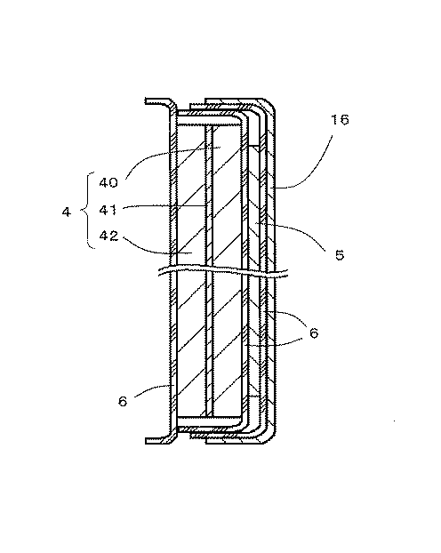
表1から明らかなように、実施例1、2の筒形非水電解液一次電池は、電池作製直後および電池使用中において異常品の発生が認められず、信頼性が非常に優れている。 As can be seen from Table 1, the cylindrical nonaqueous electrolyte primary batteries of Examples 1 and 2 are very reliable because no abnormal products are observed immediately after the battery is produced and during battery use.
これに対し、比較例1の電池は、電池作製直後において、開路電圧が3.1V以下のものが2個あり、また、放電試験中に電圧が急激に低下して容量が2500mAhに満たないものが1個あった。これらの電池を分解したところ、電池作製直後に異常品となったものは巻回電極体の下面における最外周のセパレータが外周側に折れ曲がり、正極が露出することで外装缶と一部接触していた。電池使用中に異常品となったものは、巻回電極体の上面における最外周のセパレータが蛇腹状に押しつぶされ、放電に伴って膨張した正極が露出することで、外装缶と一部接触していた。 In contrast, the batteries of Comparative Example 1 had two batteries with an open circuit voltage of 3.1 V or less immediately after the battery was manufactured, and the voltage dropped rapidly during the discharge test and the capacity was less than 2500 mAh. There was one. When these batteries were disassembled, an abnormal product immediately after the production of the battery was partially contacted with the outer can by folding the outermost separator on the lower surface of the wound electrode body to the outer peripheral side and exposing the positive electrode. It was. When the battery becomes abnormal, the outermost separator on the upper surface of the wound electrode body is crushed in a bellows shape, and the positive electrode that expands due to discharge is exposed, so that it partially contacts the outer can. It was.
1 筒形非水電解液一次電池
2 外装缶
3 巻回電極体
4 正極
5 負極
6 セパレータ
7 電池蓋
8 絶縁パッキング
9 端子体
16 電気絶縁性のフィルム
DESCRIPTION OF
Claims (3)
上記外装缶と上記電池蓋とが溶接により封止されており、
上記外装缶および上記電池蓋が負極の電位を有し、上記端子体が正極の電位を有しており、
上記巻回電極体の上側の、少なくとも、上記巻回電極体側面における最外周側の正極が最外周側の負極からはみ出している部分に相当する位置の下端から、上記巻回電極体上面における最外周側の正極の集電体の位置する箇所までが、電気絶縁性のフィルムで覆われていることにより、少なくとも最外周に位置するセパレータが、上記巻回電極体の上面において、上記巻回電極体の巻回中心側に向かって折り曲げられているか、または、
上記巻回電極体の下側の、少なくとも、上記巻回電極体側面における最外周側の正極が最外周側の負極からはみ出している部分に相当する位置の上端から、上記巻回電極体下面における最外周側の正極の集電体の位置する箇所までが、電気絶縁性のフィルムで覆われていることにより、少なくとも最外周に位置するセパレータが、上記巻回電極体の下面において、上記巻回電極体の巻回中心側に向かって折り曲げられていることを特徴とする筒形非水電解液一次電池。 Winding in which a positive electrode having a positive electrode mixture layer containing manganese dioxide or fluorinated graphite on both sides of a current collector, a negative electrode containing lithium or a lithium alloy, and a separator are wound, and the separator is disposed on the outermost periphery. A cylindrical non-aqueous electrolyte primary having a rotating electrode body and a non-aqueous electrolyte in a space formed by a bottomed cylindrical outer can and a battery lid to which a terminal body is attached via an insulating packing A battery,
The outer can and the battery lid are sealed by welding,
The outer can and the battery lid have a negative potential, the terminal body has a positive potential,
From the lower end of the upper side of the wound electrode body, at least from the lower end of the position corresponding to the portion where the positive electrode on the outermost peripheral side of the side of the wound electrode body protrudes from the negative electrode on the outermost peripheral side, By covering up to the position where the current collector of the positive electrode on the outer peripheral side is covered with an electrically insulating film, the separator positioned at least on the outermost periphery is disposed on the upper surface of the wound electrode body. It is bent towards the winding center of the body, or
From the upper end of the lower side of the wound electrode body, at least from the upper end of the position corresponding to the portion where the positive electrode on the outermost circumferential side of the side surface of the wound electrode body protrudes from the negative electrode on the outermost circumferential side, By covering up to the position where the current collector of the positive electrode on the outermost periphery side is covered with an electrically insulating film, the separator positioned at least on the outermost periphery is formed on the lower surface of the wound electrode body. A cylindrical non-aqueous electrolyte primary battery which is bent toward the winding center side of an electrode body.
上記巻回電極体の下側の、少なくとも、上記巻回電極体側面における最外周側の正極が最外周側の負極からはみ出している部分に相当する位置の上端から、上記巻回電極体下面における最外周側の正極の集電体の位置する箇所までが、電気絶縁性のフィルムで覆われていることにより、少なくとも最外周に位置するセパレータが、上記巻回電極体の下面において、上記巻回電極体の巻回中心側に向かって折り曲げられている請求項1に記載の筒形非水電解液一次電池。 From the lower end of the upper side of the wound electrode body, at least from the lower end of the position corresponding to the portion where the positive electrode on the outermost circumferential side on the side surface of the wound electrode body protrudes from the negative electrode on the outermost circumferential side, The separator located at the outermost periphery is covered with the winding electrode body on the upper surface of the winding electrode body by covering up to the position where the current collector of the positive electrode on the side is covered with an electrically insulating film Is bent toward the winding center side of the winding electrode body, and at least the outermost positive electrode on the side surface of the winding electrode body protrudes from the outermost negative electrode on the lower side of the winding electrode body. From the upper end of the corresponding position to the location where the positive electrode current collector on the outermost peripheral side on the lower surface of the spirally wound electrode body is covered with an electrically insulating film, at least the outer peripheral side The cylindrical nonaqueous electrolyte primary battery according to claim 1, wherein the parator is bent toward the winding center side of the spirally wound electrode body on the lower surface of the spirally wound electrode body.
Priority Applications (1)
| Application Number | Priority Date | Filing Date | Title |
|---|---|---|---|
| JP2007027516A JP2008192524A (en) | 2007-02-07 | 2007-02-07 | Cylindrical nonaqueous electrolyte solution primary battery |
Applications Claiming Priority (1)
| Application Number | Priority Date | Filing Date | Title |
|---|---|---|---|
| JP2007027516A JP2008192524A (en) | 2007-02-07 | 2007-02-07 | Cylindrical nonaqueous electrolyte solution primary battery |
Publications (1)
| Publication Number | Publication Date |
|---|---|
| JP2008192524A true JP2008192524A (en) | 2008-08-21 |
Family
ID=39752414
Family Applications (1)
| Application Number | Title | Priority Date | Filing Date |
|---|---|---|---|
| JP2007027516A Withdrawn JP2008192524A (en) | 2007-02-07 | 2007-02-07 | Cylindrical nonaqueous electrolyte solution primary battery |
Country Status (1)
| Country | Link |
|---|---|
| JP (1) | JP2008192524A (en) |
Cited By (5)
| Publication number | Priority date | Publication date | Assignee | Title |
|---|---|---|---|---|
| JP2009146801A (en) * | 2007-12-17 | 2009-07-02 | Panasonic Corp | Flat non-aqueous electrolytic solution battery |
| JP2013134940A (en) * | 2011-12-27 | 2013-07-08 | Fdk Twicell Co Ltd | Cylindrical battery |
| WO2021192666A1 (en) * | 2020-03-26 | 2021-09-30 | 三洋電機株式会社 | Non-aqueous electrolyte secondary battery |
| CN114072947A (en) * | 2019-07-30 | 2022-02-18 | 株式会社村田制作所 | Secondary battery, battery pack, electric tool, electric aircraft, and electric vehicle |
| WO2022254983A1 (en) * | 2021-05-31 | 2022-12-08 | パナソニックIpマネジメント株式会社 | Lithium primary battery |
-
2007
- 2007-02-07 JP JP2007027516A patent/JP2008192524A/en not_active Withdrawn
Cited By (5)
| Publication number | Priority date | Publication date | Assignee | Title |
|---|---|---|---|---|
| JP2009146801A (en) * | 2007-12-17 | 2009-07-02 | Panasonic Corp | Flat non-aqueous electrolytic solution battery |
| JP2013134940A (en) * | 2011-12-27 | 2013-07-08 | Fdk Twicell Co Ltd | Cylindrical battery |
| CN114072947A (en) * | 2019-07-30 | 2022-02-18 | 株式会社村田制作所 | Secondary battery, battery pack, electric tool, electric aircraft, and electric vehicle |
| WO2021192666A1 (en) * | 2020-03-26 | 2021-09-30 | 三洋電機株式会社 | Non-aqueous electrolyte secondary battery |
| WO2022254983A1 (en) * | 2021-05-31 | 2022-12-08 | パナソニックIpマネジメント株式会社 | Lithium primary battery |
Similar Documents
| Publication | Publication Date | Title |
|---|---|---|
| JP2003317805A (en) | Cylindrical lithium ion secondary cell, and manufacturing method of the same | |
| JP4968768B2 (en) | Cylindrical non-aqueous electrolyte battery | |
| JP5571318B2 (en) | Cylindrical battery | |
| JP2008192524A (en) | Cylindrical nonaqueous electrolyte solution primary battery | |
| JP4993860B2 (en) | Non-aqueous electrolyte primary battery | |
| JP2008192383A (en) | Cylindrical non-aqueous electrolytic liquid primary cell | |
| JP4993859B2 (en) | Non-aqueous electrolyte primary battery | |
| WO2019244818A1 (en) | Nonaqueous electrolyte secondary battery | |
| JP5620811B2 (en) | Cylindrical non-aqueous electrolyte primary battery | |
| JP5252691B2 (en) | Cylindrical non-aqueous electrolyte primary battery and manufacturing method thereof | |
| JP2006139918A (en) | Cylinder-shaped nonaqueous electrolyte battery | |
| JP4129955B2 (en) | Battery and battery manufacturing method | |
| JP4129966B2 (en) | Non-aqueous electrolyte battery | |
| JP4236193B2 (en) | Battery cover for cylindrical battery, cylindrical battery and method for manufacturing the same | |
| JP4151840B2 (en) | Non-aqueous electrolyte battery | |
| JP5019557B2 (en) | Cylindrical non-aqueous electrolyte primary battery | |
| JP2004335380A (en) | Nonaqueous electrolyte battery | |
| JP2007207640A (en) | Cylindrical non-aqueous electrolytic solution primary battery | |
| JP4255013B2 (en) | Non-aqueous electrolyte battery | |
| JP4079326B2 (en) | Non-aqueous electrolyte battery | |
| JP4129952B2 (en) | Non-aqueous electrolyte battery | |
| JP5216961B2 (en) | Non-aqueous electrolyte primary battery | |
| WO2023162823A1 (en) | Cylindrical non-aqueous electrolyte secondary battery | |
| US20230073596A1 (en) | Non-aqueous electrolytic secondary battery | |
| JP2011154788A (en) | Battery |
Legal Events
| Date | Code | Title | Description |
|---|---|---|---|
| A300 | Withdrawal of application because of no request for examination |
Free format text: JAPANESE INTERMEDIATE CODE: A300 Effective date: 20100511 |