JP2008175437A - Refrigerator - Google Patents
Refrigerator Download PDFInfo
- Publication number
- JP2008175437A JP2008175437A JP2007008133A JP2007008133A JP2008175437A JP 2008175437 A JP2008175437 A JP 2008175437A JP 2007008133 A JP2007008133 A JP 2007008133A JP 2007008133 A JP2007008133 A JP 2007008133A JP 2008175437 A JP2008175437 A JP 2008175437A
- Authority
- JP
- Japan
- Prior art keywords
- heater
- heaters
- temperature
- refrigerator
- control
- Prior art date
- Legal status (The legal status is an assumption and is not a legal conclusion. Google has not performed a legal analysis and makes no representation as to the accuracy of the status listed.)
- Withdrawn
Links
Images


Abstract
Description
この発明は冷蔵庫に関し、特に部品種類の削減に関するものである。 The present invention relates to a refrigerator, and more particularly, to reduction of component types.
従来の冷蔵庫としては、例えば「温度センサの検出外気温度に基づいてスイッチング素子のオンオフ制御を行って防露用の電気ヒータの通断電を制御する。この場合、電気ヒータの発熱量が最適な値となり、従って、消費電力の無駄がなくなる。」(例えば特許文献1参照)というものが提案されている。 As a conventional refrigerator, for example, “on / off control of the switching element is performed based on the detected outside air temperature of the temperature sensor to control the power interruption of the electric heater for dew prevention. In this case, the amount of heat generated by the electric heater is optimal. Therefore, there is no need to waste power consumption ”(see, for example, Patent Document 1).
上記の特許文献1で提案されている冷蔵庫においては、結露防止にあたり別定格のヒータを設ける必要がなくなっており、部品種類の削減や、運転コストの低減に成功している。しかし、近年は同一の箱体に、冷凍室、冷蔵室のみならず、チルド室、野菜室、切替室など多数の温度帯室が設けられており、各温度帯室の温度制御が複雑化している。これに伴い、冷蔵庫で使用するヒータは、従来に比べて数、種類とも増加しており、部品在庫の増加をもたらしているという問題点がある。また、ヒータの数、種類の増加に伴い、冷蔵庫製造工程においてヒータの取付間違いが生じるという問題もあった。
In the refrigerator proposed in
この発明は、上述のような課題を解決するためになされたものであり、第1の目的は、設置箇所及び使用目的の異なる複数のヒータを同定格のヒータに共通化することにより、従来に比べ部品種類の少ない冷蔵庫を得ることにある。また、第2の目的は、ヒータの共通化によって、冷蔵庫製造工程においてヒータの取付間違いを防止できる冷蔵庫を得ることにある。 The present invention has been made in order to solve the above-described problems. The first object of the present invention is to provide a plurality of heaters having different installation locations and usage purposes in common with heaters of the same rating. The purpose is to obtain a refrigerator with fewer types of parts. Moreover, the 2nd objective is to obtain the refrigerator which can prevent the attachment mistake of a heater in a refrigerator manufacturing process by sharing a heater.
この発明に係る冷蔵庫は、内部が1つまたは複数の温度帯室に区分された箱体と、この温度帯室内を冷却する冷却装置と、この冷却装置を制御して前記温度帯室を設定値に保つ温度制御部とを備えた冷蔵庫において、前記温度帯室が設定温度以下になることを防止する温度補償用ヒータ及び前記箱体への結露を防止する結露防止用ヒータからなる複数のヒータと、前記複数のヒータへの通電をそれぞれ制御するスイッチング素子と、前記スイッチング素子をオンオフ制御する制御手段とを備え、前記複数のヒータの定格を同一とし、前記制御手段は、各ヒータがその使用箇所及び使用目的に応じた熱量となるように、各ヒータに対応した通電率が設定された通電率テーブルに従って前記スイッチング素子をオンオフ制御するものである。 The refrigerator according to the present invention includes a box whose interior is divided into one or a plurality of temperature zone chambers, a cooling device that cools the temperature zone chamber, and a control device that controls the cooling device to set the temperature zone chamber to a set value. A plurality of heaters comprising a temperature compensation heater for preventing the temperature zone chamber from becoming a set temperature or lower and a condensation prevention heater for preventing condensation on the box. A switching element that controls energization to each of the plurality of heaters, and a control unit that controls on / off of the switching element, wherein the ratings of the plurality of heaters are the same. In addition, the switching element is on / off controlled in accordance with an energization rate table in which an energization rate corresponding to each heater is set so that the amount of heat corresponding to the purpose of use is obtained.
この発明においては、複数のヒータの定格を同一にしたので、冷蔵庫の部品種類を削減することができるとともに、冷蔵庫製造工程においてヒータの取付間違いを防止できる。また、各ヒータ毎に設定された通電率テーブルに従ってスイッチング素子をオンオフ制御するようにしたので、各ヒータの設置箇所及び使用目的に応じた熱量が得られる。 In this invention, since the ratings of the plurality of heaters are made the same, it is possible to reduce the number of parts of the refrigerator, and to prevent the heater from being mistaken in the refrigerator manufacturing process. Further, since the switching elements are controlled to be turned on / off according to the energization rate table set for each heater, the amount of heat corresponding to the installation location and purpose of use of each heater can be obtained.
実施の形態1
図1は、この発明の実施の形態1に係る冷蔵庫本体1の前面図を示すものである。箱体である冷蔵庫本体1には、温度帯室として上から冷蔵室2、製氷室3、切替室4、野菜室5、及び冷凍室6が設けられている。これら各温度帯室の開口された前面部にはそれぞれに対応して観音開き型の冷蔵室用扉2a,2b、製氷室用扉3a、切替室用扉4a、野菜室用扉5a、及び冷凍室用扉6aが設けられている。冷蔵室用の観音開き型扉2a,2bが接する位置には結露防止用ヒータ7が内蔵されており、製氷室用扉3a、切替室用扉4aが接する位置には結露防止用ヒータ8が内蔵されている。
FIG. 1 shows a front view of a
図2は、図1の冷蔵庫本体1の右側面から見た断面図を示すものである。切替室4の後部には、切替室内が設定温度以下になることを防止する温度補償用ヒータ9が内蔵されている。野菜室5の後部と、野菜室5と冷凍室6の境界の仕切壁内部には、野菜室内が設定温度以下になることを防止する温度補償用ヒータ10が内蔵されている。
また、冷蔵庫本体1後部には、各温度帯室を冷却するための冷却装置である蒸発器12及びファンモータ13が設けられている。
FIG. 2 shows a cross-sectional view of the refrigerator
Moreover, the evaporator 12 and the fan motor 13 which are cooling devices for cooling each temperature zone room are provided in the rear part of the refrigerator
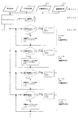
図3は、この発明の実施の形態1における回路構成図を示すものである。結露防止用ヒータ7,8及び温度補償用ヒータ9,10には、その中で必要熱量が最大となるヒータと同じものが備えられている(例えば必要熱量最大となるヒータ10の10Wにヒータ7〜9を合わせる)。これらヒータ7〜10はそれぞれに対応して、スイッチング素子であるフォトトライアックカプラ7a〜10aを介して交流電源7b〜10bに接続されている。これらフォトトライアックカプラ7a〜10aは、それぞれトランジスタ7c〜10cを介してマイクロコンピュータ14に接続されている。また、このマイクロコンピュータ14には、外気温度及び冷蔵庫本体1の冷蔵室2と切替室4と野菜室5の室内温度をそれぞれ計測するサーミスタ7d〜10dが接続されており、各室温度設定15及び扉の開閉状態16の情報が入力されている。
なお、2点鎖線で囲まれた範囲に示す交流電源11b及びゼロクロス検出回路17は、後述する実施の形態2における回路構成要素である。
FIG. 3 shows a circuit configuration diagram according to the first embodiment of the present invention. The dew
The AC power supply 11b and the zero
図4は、この発明の実施の形態1における制御フローチャートを示すものである。ステップ1として、マイクロコンピュータ14はサーミスタ8d〜10dより得られた各室内温度、各室温度設定15及び扉の開閉状態16など(以降、冷蔵庫動作状態と呼ぶ)とサーミスタ7dより得られた外気温度を読み取る。ステップ2として、読み取った情報を元に、通電率テーブルから通電率を選択する。通電率テーブルは、外気温度及び冷蔵庫動作状態との関係から必要な熱量が得られるように設定されている。ステップ3として、マイクロコンピュータ14が選択した通電率に従ってトランジスタ7c〜10cをオンオフ制御する。このことによって、例えば、ヒータ7を8W、ヒータ8を4W、ヒータ9を5W、及びヒータ10を10Wに制御する。なお、通電率とは、基準時間内に占めるこの同定格ヒータに通電される時間の割合をいうものとする。
FIG. 4 shows a control flowchart according to the first embodiment of the present invention. As
はじめに、温度補償用ヒータ9,10の制御を説明する。
マイクロコンピュータ14はサーミスタ7d〜10dより得られた外気温度及び冷蔵庫動作状態を基に上記の通電率テーブルから通電率を選択する。そして、その通電率に基づいてトランジスタ9c,10cをオンオフ制御する。例えばトランジスタ9cがオンすると、フォトトライアックカプラ9aによって温度補償用ヒータ9の通電経路が開かれ、温度補償用ヒータ9は通電される。トランジスタ9cがオフすると、フォトトライアックカプラ9aによって温度補償用ヒータ9の通電経路が遮断され、温度補償用ヒータ9の通電は中止される。このような制御により温度補償用ヒータ9の通電率が制御され、温度補償用ヒータ9は切替室4内温度を設定温度に補償するのに必要な熱量に制御される。同様にして、温度補償用ヒータ10も、マイクロコンピュータ14が上記通電率テーブルから選択した通電率に基づいて野菜室5内温度を設定温度に補償するのに必要な熱量に制御される。
First, control of the
The microcomputer 14 selects an energization rate from the above energization rate table based on the outside air temperature and the refrigerator operating state obtained from the thermistors 7d to 10d. Then, the
ここで、温度補償用ヒータ9,10を最適熱量に制御するのは、切替室4及び野菜室5内の食品に悪影響を与えないためである。温度補償用ヒータ9,10は外気温度が切替室4及び野菜室5内温度より低い場合等、室内温度が設定温度以下になることを防止する目的で設置されている。この目的を達成するために必要なヒータ熱量は、外気温度、温度帯室の各室温度設定15、冷蔵庫の温度帯室構成及び室内空間容積等から、例えば温度補償用ヒータ9が5W、温度補償用ヒータ10が10Wと求められる。ここで、温度補償用ヒータ9に取り付けるヒータの熱量を10Wと温度補償用ヒータ10に合わせることによって、温度補償用ヒータ9,10を共通化できる。しかし、温度補償用ヒータ9が過大熱量となり食品に悪影響を及ぼすため、温度補償用ヒータ9をマイクロコンピュータ14とトランジスタ9cにより、5Wとなるよう通電率を制御する。
Here, the reason why the
また、マイクロコンピュータ14内にある、温度補償用ヒータ9,10の通電率テーブルには、温度補償用ヒータ9,10がそれぞれ過大な熱量にならないように、温度補償用ヒータ9,10に対し、上限の通電率が定められており、規定値を上回る通電率の指令がマイクロコンピュータ13に入力されても通電率が変更されないように対策されている。これにより、ノイズなどによって規定値を上回る通電率の指令がマイクロコンピュータ13に入力されても、温度補償用ヒータ9,10付近の温度が一時的に設定温度以上に上昇し、食品に悪影響を及ぼすことはない。
Further, in the energization rate table of the
次に、結露防止用ヒータ7,8の制御について説明する。
マイクロコンピュータ14は、サーミスタ7dより得られた外気温度及び冷蔵庫動作状態より上記の通電率テーブルから通電率を選択する。そして、その通電率に基づいてトランジスタ7c,8cをオンオフ制御する。例えばトランジスタ7cがオンすると、フォトトライアックカプラ7aによって結露防止用ヒータ7の通電経路が開かれ、結露防止用ヒータ7は通電される。トランジスタ7cがオフすると、フォトトライアックカプラ7aによって結露防止用ヒータ7の通電経路が遮断され、結露防止用ヒータ7の通電は中止される。このような制御により結露防止用ヒータ7の通電率が制御され、結露防止用ヒータ7は結露防止に必要な熱量に制御される。同様にして、結露防止用ヒータ8も、マイクロコンピュータ14が通電率テーブルから選択した通電率に基づいて結露防止に必要な熱量に制御される。
Next, control of the dew
The microcomputer 14 selects an energization rate from the above energization rate table based on the outside air temperature obtained from the thermistor 7d and the refrigerator operating state. Then, the
ここで、通電率テーブルにしたがって結露防止用ヒータ7,8がそれぞれ結露防止に必要な熱量に制御するのは、運転コスト低減を図るためである。一般に、冷蔵庫においては外気温度と温度室帯との温度差により、温度帯室の開口部の縁には結露が生じやすい。開口部の温度が外気温度と同程度かそれよりも高ければ結露を生じないので、真夏等の外気温度が高い場合を想定して、結露防止用ヒータ7,8の必要とする熱量を決定する。例えば、外気と触れ合う面積が大きい結露防止用ヒータ7は8W、外気と触れ合う面積が小さい結露防止用ヒータ8は4Wと求められる。結露防止用ヒータ7,8の定格熱量を最大熱量となる温度補償用ヒータ10の10Wに合わせると各ヒータの共通化が図れるが、余分な運転コストが発生する。そこで、結露防止用ヒータ8の熱量が4Wとなるようにマイクロコンピュータ14によってトランジスタ8cをオンオフ制御する。結露防止用ヒータ7は外気と触れ合う面積が大きいため、例えば結露防止用ヒータ8と同ヒータを3個使用し、合計のヒータ熱量が8Wとなるようにマイクロコンピュータ14によってトランジスタ7cをオンオフ制御する。
Here, the reason why the dew
冬期等の外気温度が低い場合や、結露防止用ヒータ7と結露防止用ヒータ8のうち必要熱量の低いヒータを運転する際にも、余分な運転コストが発生するため、結露防止用ヒータ7,8を、トランジスタ7c,8cをオンオフ制御することにより最適な熱量に制御し、運転コストを低減しながら、ヒータの共通化による部品種類の削減を図っている。
When the outside air temperature is low, such as in winter, or when operating a heater with a low required heat quantity among the
また、マイクロコンピュータ14内にある、結露防止用ヒータ7,8の通電率テーブルには、結露防止用ヒータ7,8がそれぞれ過大な熱量にならないように、結露防止用ヒータ7,8に対し、上限の通電率が定められており、規定値を上回る通電率の指令がマイクロコンピュータ13に入力されても通電率が変更されないように対策されている。これにより、ノイズなどによって規定値を上回る通電率の指令がマイクロコンピュータ13に入力されても、消費電力の無駄が生じ、運転コストが増大することはない。
Further, in the energization rate table of the dew
図5に通電率制御のタイムチャートの一例を示す。図5(a),(b),(c)及び(d)はそれぞれ通電率80パーセント、40パーセント、50パーセント及び100パーセントの時のタイムチャートである。本実施形態1では、10s内の通電時間を制御することでヒータ熱量を制御しているが、通電時間の割合が等しければ特に基準とする時間は問わない。 FIG. 5 shows an example of a time chart for energization rate control. FIGS. 5A, 5B, 5C and 5D are time charts when the energization rates are 80%, 40%, 50% and 100%, respectively. In the first embodiment, the amount of heat of the heater is controlled by controlling the energization time within 10 s, but the reference time is not particularly limited as long as the ratio of the energization time is equal.
また、本実施形態1ではスイッチング素子としてフォトトライアックカプラとトランジスタを用いる構成としたが、これに限らず、サイリスタ、FET或いはリレー等のスイッチング素子を用いることもできる。 In the first embodiment, the phototriac coupler and the transistor are used as the switching elements. However, the present invention is not limited to this, and a switching element such as a thyristor, FET, or relay can be used.
このように構成された冷蔵庫本体1においては、設置箇所及び使用目的の異なる結露防止用ヒータ7,8、及び温度補償用ヒータ9,10に同定格のヒータを設置でき、それぞれのヒータ目的に応じた熱量に制御することができる。したがって、ヒータ種類を1種類で共通化できる。
In the refrigerator
さらに、冷蔵庫製造工程における結露防止用ヒータ7,8、及び温度補償用ヒータ9,10の取付間違いを防止することができる。
Further, it is possible to prevent erroneous installation of the dew
実施の形態2
実施の形態1では、結露防止用ヒータ7,8と温度補償用ヒータ9,10のヒータ熱量を制御するのに、トランジスタ7cから10cを通電率テーブルに従って時間でオンオフ制御したが、図3の2点鎖線で囲まれた範囲に示すゼロクロス検出回路を本実施形態1に設けることで、トランジスタ7cから10cを位相テーブルに従って通電位相角でオンオフ制御することもできる。図6に、ゼロクロス検出の一例を示す。ここで、位相制御テーブルとは、結露防止用ヒータ7,8と温度補償用ヒータ9,10で共通に使用されている同定格のヒータを所定の熱量に制御するために、この同定格ヒータに通電を開始するゼロクロスからの位相角がまとめられたテーブルをいうものである。この位相制御テーブルは、通電率テーブルの場合と同様に、結露防止用ヒータ7,8及び温度補償用ヒータ9,10は外気温度及び冷蔵庫動作状態と制御位相との関係がそれぞれ設定されており、その目的に応じた適切な熱量が発生するようにしている。
In the first embodiment, the
本実施形態2においても、実施の形態1と同様に、設置箇所及び使用目的の異なる結露防止用ヒータ7,8、及び温度補償用ヒータ9,10は同定格のヒータを設置でき、それぞれの設置箇所及び使用目的に応じた熱量に制御することで、ヒータの共通化による部品種類の削減を図ることができる。
Also in the second embodiment, as in the first embodiment, the dew
また、マイクロコンピュータ14内にある、結露防止用ヒータ7,8と温度補償用ヒータ9,10の位相制御テーブルには、各ヒータごとに下限の位相角が定められている。これにより、ノイズなどによって規定値を下回る指令がマイクロコンピュータ14に入力されても通電する位相角が変更されないように対策されている。
In the phase control table of the dew
図7は、位相制御テーブルに従ってヒータ熱量を制御したときの、ヒータ電流波形の一例である。図7(a),(b),(c)及び(d)はそれぞれ通電率80パーセント、40パーセント、50パーセント及び100パーセントとなるように位相角を制御している。なお、本実施形態2では、1周期を基準に位相角でオンオフ制御したが、半周期、または複数の周期を基準にオンオフ制御しても良い。例えば、図8に6周期を基準として通電率50パーセントに位相制御したヒータ電流波形の一例を示す。 FIG. 7 is an example of a heater current waveform when the heater heat quantity is controlled according to the phase control table. 7A, 7B, 7C, and 7D control the phase angle so that the energization rates are 80%, 40%, 50%, and 100%, respectively. In the second embodiment, on / off control is performed with a phase angle based on one cycle, but on / off control may be performed based on a half cycle or a plurality of cycles. For example, FIG. 8 shows an example of a heater current waveform whose phase is controlled to 50% energization rate based on six cycles.
1 冷蔵庫本体、2 冷蔵庫、2a 冷蔵室用扉、2b 冷蔵室用扉、3 製氷室、3a 製氷室用扉、4 切替室、4a 切替室用扉、5 野菜室、5a 野菜室用扉、6 冷凍室、6a 冷凍室用扉、7 結露防止用ヒータ、7a フォトトライアックカプラ、7b 交流電源、7c トランジスタ、7d サーミスタ、8 結露防止用ヒータ、8a フォトトライアックカプラ、8b 交流電源、8c トランジスタ、8d サーミスタ、9 温度補償用ヒータ、9a フォトトライアックカプラ、9b 交流電源、9c トランジスタ、9d サーミスタ、10 温度補償用ヒータ、10a フォトトライアックカプラ、10b 交流電源、10c トランジスタ、10d サーミスタ、11b 交流電源、12 蒸発器、13 ファンモータ、14 マイクロコンピュータ、15 各室温度設定、16扉開閉状態、17 ゼロクロス検出回路。 1 Refrigerator body, 2 Refrigerator, 2a Door for refrigeration room, 2b Door for refrigeration room, 3 Ice making room, 3a Door for ice making room, 4 Switching room, 4a Door for switching room, 5 Vegetable room, 5a Door for vegetable room, 6 Freezer compartment, 6a Freezer compartment door, 7 Condensation prevention heater, 7a Phototriac coupler, 7b AC power supply, 7c transistor, 7d thermistor, 8 Condensation prevention heater, 8a Phototriac coupler, 8b AC power supply, 8c transistor, 8d thermistor , 9 Temperature compensation heater, 9a Phototriac coupler, 9b AC power supply, 9c transistor, 9d thermistor, 10 Temperature compensation heater, 10a Phototriac coupler, 10b AC power supply, 10c transistor, 10d thermistor, 11b AC power supply, 12 Evaporator , 13 Fan motor, 14 Microphone Computer, 15 chambers temperature setting, 16 door open or closed, 17 zero-crossing detection circuit.
Claims (2)
この温度帯室内を冷却する冷却装置と、
この冷却装置を制御して前記温度帯室を設定値に保つ温度制御部と
を備えた冷蔵庫において、
前記温度帯室が設定温度以下になることを防止する温度補償用ヒータ及び前記箱体への結露を防止する結露防止用ヒータからなる複数のヒータと、
前記複数のヒータへの通電をそれぞれ制御するスイッチング素子と、
前記スイッチング素子をオンオフ制御する制御手段とを備え、
前記複数のヒータの定格を同一とし、
前記制御手段は、各ヒータがその使用箇所及び使用目的に応じた熱量となるように、各ヒータに対応した通電率が設定された通電率テーブルに従って前記スイッチング素子をオンオフ制御することを特徴とする冷蔵庫。 A box whose interior is divided into one or more temperature zone chambers;
A cooling device for cooling the interior of the temperature zone;
In a refrigerator including a temperature control unit that controls the cooling device and keeps the temperature zone chamber at a set value,
A plurality of heaters comprising a temperature compensation heater for preventing the temperature zone chamber from becoming a set temperature or less and a condensation prevention heater for preventing condensation on the box;
Switching elements that respectively control energization to the plurality of heaters;
Control means for controlling on / off of the switching element,
The ratings of the plurality of heaters are the same,
The control means performs on / off control of the switching element according to an energization rate table in which an energization rate corresponding to each heater is set so that each heater has an amount of heat corresponding to the use location and purpose of use. refrigerator.
この温度帯室内を冷却する冷却装置と、
この冷却装置を制御して前記温度帯室を設定値に保つ温度制御部と
を備えた冷蔵庫において、
前記温度帯室が設定温度以下になることを防止する温度補償用ヒータ及び前記箱体への結露を防止する結露防止用ヒータからなる複数のヒータと、
前記複数のヒータへの通電をそれぞれ制御するスイッチング素子と、
前記スイッチング素子をオンオフ制御する制御手段とを備え、
前記複数のヒータの定格を同一とし、
前記制御手段は、各ヒータがその使用箇所及び使用目的に応じた熱量となるように、各ヒータに対応した制御位相が設定された位相制御テーブルに従って前記スイッチング素子をオンオフ制御することを特徴とする冷蔵庫。 A box whose interior is divided into one or more temperature zone chambers;
A cooling device for cooling the interior of the temperature zone;
In a refrigerator including a temperature control unit that controls the cooling device and keeps the temperature zone chamber at a set value,
A plurality of heaters comprising a temperature compensation heater for preventing the temperature zone chamber from becoming a set temperature or less and a condensation prevention heater for preventing condensation on the box;
Switching elements that respectively control energization to the plurality of heaters;
Control means for controlling on / off of the switching element,
The ratings of the plurality of heaters are the same,
The control means performs on / off control of the switching element according to a phase control table in which a control phase corresponding to each heater is set so that each heater has an amount of heat corresponding to the use location and purpose of use. refrigerator.
Priority Applications (1)
| Application Number | Priority Date | Filing Date | Title |
|---|---|---|---|
| JP2007008133A JP2008175437A (en) | 2007-01-17 | 2007-01-17 | Refrigerator |
Applications Claiming Priority (1)
| Application Number | Priority Date | Filing Date | Title |
|---|---|---|---|
| JP2007008133A JP2008175437A (en) | 2007-01-17 | 2007-01-17 | Refrigerator |
Publications (1)
| Publication Number | Publication Date |
|---|---|
| JP2008175437A true JP2008175437A (en) | 2008-07-31 |
Family
ID=39702583
Family Applications (1)
| Application Number | Title | Priority Date | Filing Date |
|---|---|---|---|
| JP2007008133A Withdrawn JP2008175437A (en) | 2007-01-17 | 2007-01-17 | Refrigerator |
Country Status (1)
| Country | Link |
|---|---|
| JP (1) | JP2008175437A (en) |
Cited By (5)
| Publication number | Priority date | Publication date | Assignee | Title |
|---|---|---|---|---|
| JP2010230223A (en) * | 2009-03-26 | 2010-10-14 | Haier Sanyo Electric Co Ltd | Refrigerator-freezer |
| JP6096859B1 (en) * | 2015-10-20 | 2017-03-15 | 三菱電機株式会社 | refrigerator |
| US11454677B2 (en) | 2016-07-01 | 2022-09-27 | Weber-Stephen Products Llc | Wireless control and status monitoring for electric grill with current protection circuitry |
| US11622420B2 (en) | 2016-07-01 | 2023-04-04 | Weber-Stephen Products Llc | Electric grill with current protection circuitry |
| US11703928B2 (en) | 2016-07-01 | 2023-07-18 | Weber-Stephen Products Llc | Digital power supply with wireless monitoring and control |
-
2007
- 2007-01-17 JP JP2007008133A patent/JP2008175437A/en not_active Withdrawn
Cited By (7)
| Publication number | Priority date | Publication date | Assignee | Title |
|---|---|---|---|---|
| JP2010230223A (en) * | 2009-03-26 | 2010-10-14 | Haier Sanyo Electric Co Ltd | Refrigerator-freezer |
| JP6096859B1 (en) * | 2015-10-20 | 2017-03-15 | 三菱電機株式会社 | refrigerator |
| JP2017078538A (en) * | 2015-10-20 | 2017-04-27 | 三菱電機株式会社 | refrigerator |
| US11454677B2 (en) | 2016-07-01 | 2022-09-27 | Weber-Stephen Products Llc | Wireless control and status monitoring for electric grill with current protection circuitry |
| US11622420B2 (en) | 2016-07-01 | 2023-04-04 | Weber-Stephen Products Llc | Electric grill with current protection circuitry |
| US11703928B2 (en) | 2016-07-01 | 2023-07-18 | Weber-Stephen Products Llc | Digital power supply with wireless monitoring and control |
| US11860240B2 (en) | 2016-07-01 | 2024-01-02 | Weber-Stephen Products Llc | Wireless control and status monitoring for electric grill with current protection circuitry |
Similar Documents
| Publication | Publication Date | Title |
|---|---|---|
| JP2000329445A (en) | Low temperature storage chamber | |
| JP4945395B2 (en) | refrigerator | |
| SI22068A (en) | Control of a fridge-freezer appliance | |
| JP2008175437A (en) | Refrigerator | |
| JP3952007B2 (en) | refrigerator | |
| JP2004353972A (en) | Refrigerator | |
| JP2008542673A (en) | Refrigerator unit and / or refrigerator unit | |
| JP3942688B2 (en) | refrigerator | |
| JP2001349659A (en) | Refrigerator | |
| JP2007292378A (en) | Low temperature storage | |
| EP2085725A2 (en) | Refrigerator and method of controlling the same | |
| AU2015410544B2 (en) | Refrigerator | |
| JP2007010232A (en) | Cooling system | |
| JP2007101163A (en) | Cooling storage | |
| US20170067683A1 (en) | Mechanical refrigerator | |
| JP7321946B2 (en) | refrigerator | |
| JP2014142121A (en) | Refrigerator | |
| JP3426504B2 (en) | Cooling storage | |
| JP2007120912A (en) | Refrigerator | |
| WO2019193626A1 (en) | Refrigeration appliance | |
| JP6543799B2 (en) | refrigerator | |
| JP7305519B2 (en) | refrigerator | |
| JP2008070041A (en) | Refrigerator | |
| JPH0247424Y2 (en) | ||
| KR100485938B1 (en) | The method for controlling fixed temperature of a refrigerator |
Legal Events
| Date | Code | Title | Description |
|---|---|---|---|
| A300 | Withdrawal of application because of no request for examination |
Free format text: JAPANESE INTERMEDIATE CODE: A300 Effective date: 20100406 |