JP2008173281A - Game machine - Google Patents

Game machine Download PDF

Info

Publication number
JP2008173281A
JP2008173281A JP2007008996A JP2007008996A JP2008173281A JP 2008173281 A JP2008173281 A JP 2008173281A JP 2007008996 A JP2007008996 A JP 2007008996A JP 2007008996 A JP2007008996 A JP 2007008996A JP 2008173281 A JP2008173281 A JP 2008173281A
Authority
JP
Japan
Prior art keywords
game
display
state
reach
big hit
Prior art date
Legal status (The legal status is an assumption and is not a legal conclusion. Google has not performed a legal analysis and makes no representation as to the accuracy of the status listed.)
Pending
Application number
JP2007008996A
Other languages
Japanese (ja)
Other versions
JP2008173281A5 (en
Inventor
Takaaki Ichihara
高明 市原
Nobuyuki Kuritani
信行 栗谷
Current Assignee (The listed assignees may be inaccurate. Google has not performed a legal analysis and makes no representation or warranty as to the accuracy of the list.)
Daiichi Shokai Co Ltd
Original Assignee
Daiichi Shokai Co Ltd
Priority date (The priority date is an assumption and is not a legal conclusion. Google has not performed a legal analysis and makes no representation as to the accuracy of the date listed.)
Filing date
Publication date
Application filed by Daiichi Shokai Co Ltd filed Critical Daiichi Shokai Co Ltd
Priority to JP2007008996A priority Critical patent/JP2008173281A/en
Publication of JP2008173281A publication Critical patent/JP2008173281A/en
Publication of JP2008173281A5 publication Critical patent/JP2008173281A5/ja
Pending legal-status Critical Current

Links

Images

Abstract

<P>PROBLEM TO BE SOLVED: To provide a game machine capable of reflecting the preference of the player on a performance form when starting the game without giving a bitter feeling of ending a game in the middle to a player, in the configuration of selectively executing the performance form from two or more kinds. <P>SOLUTION: When the player ends the game, a password for specifying a game state including the performance form at the point of ending the game is output. Then, when the password is input when playing the game next, the game is started in the game state specified by the password. Thus, the player is prevented from having the bitter feeling of ending the game in the middle. Also, forced game start continuously taking over the remaining performance form is evaded, and the preference of the player is reflected on the performance form when starting the game. <P>COPYRIGHT: (C)2008,JPO&INPIT

Description

本発明は、所定の判定条件が成立したことに基づいて遊技者に利益を付与すべきか否かの判定を行う当落判定手段と、該当落判定手段により遊技者に利益を付与すべき判定がなされたことに基づいて遊技者に利益を付与する利益付与状態に制御する利益付与状態制御手段と、を備えた遊技機に関するものである。   In the present invention, a winning judgment means for judging whether or not to give a profit to a player based on the establishment of a predetermined judgment condition, and a judgment to give a profit to the player by the corresponding judgment means. The present invention relates to a gaming machine provided with a profit granting state control means for controlling to a profit granting state that grants a profit to a player based on the fact.

従来、一般に、遊技機としてのパチンコ機には、遊技球が始動入賞口に入賞したことに基づいて表示器(表示手段)にて図柄(識別情報)の変動表示を行って所定期間経過後に表示器に図柄を停止表示させ、表示器に停止表示される図柄が特定の表示態様(特定表示結果)となったときに大当り遊技状態(利益付与状態)に制御することにより遊技者に利益を付与するものがあった。また、この種のパチンコ機では、所定条件の成立に伴って、表示器による演出形態を通常時の演出形態とは異なる特別演出形態に切り替える(例えば、表示器の背景画面を通常時とは異なる背景画面に切り替える等)ことで、表示器での変動表示に変化を与え、演出表示に対する興趣を低下させないようにしたもの(例えば、特許文献1参照)が提案されている。具体的に、特別演出形態をミッション演出(指令演出)の形態として表示制御するものがあり、この場合には、通常時の演出形態から特別演出形態に切り替える時点で、遊技者に指令を提示し(例えば、所定回数の図柄変動が終了するまでに、特定のリーチを出せや所定の図柄でリーチを出せ等)、その指令が達成されると、特定表示結果の停止表示以前に大当りを確定させる構成となっていた。
特開2005−323763号公報(図6)
Conventionally, in general, a pachinko machine as a gaming machine displays a change of a symbol (identification information) on a display (display means) based on the fact that a game ball has won a start winning opening and displays it after a predetermined period of time has elapsed. Profits are given to the player by controlling the jackpot gaming state (profit granting state) when the symbol is stopped and displayed on the display, and when the display stopped on the display is in a specific display mode (specific display result) There was something to do. In addition, in this type of pachinko machine, as the predetermined condition is established, the effect form by the display is switched to a special effect form different from the effect form at the normal time (for example, the background screen of the display device is different from the normal time). By changing to a background screen, etc., a display that changes the display of variation on the display unit so as not to reduce the interest in the effect display (for example, see Patent Document 1) has been proposed. Specifically, there is a display control of a special effect form as a mission effect (command effect) form. In this case, a command is presented to the player at the time of switching from the normal effect form to the special effect form. (For example, a specific reach can be issued before reaching a predetermined number of symbol fluctuations, or a reach can be generated with a predetermined symbol, etc.) When the command is achieved, the big hit is confirmed before the specific display result is stopped. It was a composition.
Japanese Patent Laying-Open No. 2005-323863 (FIG. 6)

ところで、上記特許文献1のように複数種類の演出形態(例えば、通常時の演出形態と特別演出形態)の中からいずれかの演出形態を選択する構成では、遊技者の意思に関わらないパチンコ機側の制御によって所定条件が成立したか否かを判定(例えば、乱数抽出に基づいた判定や、ミッション演出形態の場合では所定回数の図柄変動が終了したか否かの判定)し、その判定結果に基づいて演出形態を切り替えるか否かを決定するようになっていた。このため、やむを得ずミッション演出形態の途中で遊技を終了するような場合、即ち、ミッション演出形態を終了させる所定回数の図柄変動が終了していないうちに遊技を終えるような場合、中途半端に遊技を終えるような後味の悪い思いを遊技者に与えていた。また、遊技者が遊技を終了する場合、遊技終了時点の演出形態がそのまま継続的に残ることになる。このため、次に遊技を行う遊技者は、継続的に残った演出形態を引き継いで遊技を開始することが強いられることになり、遊技開始時において、演出形態に対して遊技者の好みを反映させることは不可能であった。本発明は、上記した事情に鑑みなされたもので、その目的とするところは、演出形態を複数種類の中から選択的に実行する構成において、中途半端に遊技を終えるような後味の悪い思いを遊技者に与えることがなく、然も遊技開始時に演出形態に対して遊技者の好みを反映させることができる遊技機を提供することにある。   By the way, the pachinko machine which does not relate to a player's intention in the structure which selects any production form from the multiple types of production forms (for example, the production form and the special production form at the time of normal time) like the said patent document 1. It is determined whether or not a predetermined condition is established by the control on the side (for example, determination based on random number extraction or determination of whether or not a predetermined number of symbol variations have been completed in the case of a mission effect form), and the determination result Whether or not to switch the production form is determined based on this. For this reason, when the game is unavoidably terminated in the middle of the mission effect form, that is, when the game is finished before the predetermined number of symbol variations for ending the mission effect form is finished, the game is halfway. The player had a bad aftertaste to finish. Further, when the player finishes the game, the effect form at the end of the game remains as it is. For this reason, the next player who plays the game will be forced to start the game by taking over the remaining effect form, and reflect the player's preference to the effect form at the start of the game. It was impossible. The present invention has been made in view of the above-described circumstances, and the object of the present invention is to have a bad aftertaste of finishing a game halfway in a configuration in which a production form is selectively executed from a plurality of types. An object of the present invention is to provide a gaming machine that can reflect a player's preference with respect to an effect form at the start of the game without giving it to the player.

(解決手段1)
上記目的を達成するために、本発明の遊技機は、所定の判定条件が成立したことに基づいて遊技者に利益を付与すべきか否かの判定を行う当落判定手段と、該当落判定手段により遊技者に利益を付与すべき判定がなされたことに基づいて遊技者に利益を付与する利益付与状態に制御する利益付与状態制御手段と、を備えた遊技機であって、遊技に伴う演出が表示される表示手段と、前記当落判定手段の判定結果に基づいて前記表示手段にて識別情報の変動表示を行って所定期間経過後に前記判定結果に応じた識別情報の表示結果を停止表示すると共に、前記当落判定手段により遊技者に利益を付与すべき判定がなされたときに前記識別情報の表示結果として特定表示結果を停止表示する表示制御手段と、前記識別情報の変動表示における演出形態を複数種類の中から選択する演出形態選択手段と、該演出形態選択手段によって選択された演出形態を表示制御する演出形態表示制御手段と、遊技終了時点における前記演出形態を含んだ遊技状態を特定するための遊技状態特定情報を出力する特定情報出力手段と、遊技者の操作に基づいて前記遊技状態特定情報を入力する特定情報入力手段と、該特定情報入力手段から入力された前記遊技状態特定情報に基づいて当該遊技状態特定情報が特定する遊技状態で遊技を開始させる遊技状態特定開始手段と、を備えたことを特徴とする。
この場合、遊技者が遊技を終了する際には、遊技終了時点における演出形態を含んだ遊技状態を特定するための遊技状態特定情報が特定情報出力手段から出力される。そして、次に遊技を行う際に、特定情報入力手段から遊技状態特定情報を入力すると、当該遊技状態特定情報が特定する遊技状態で遊技を開始させることができる。このため、やむを得ず所定の演出形態(例えば、ミッション演出形態)の途中で遊技を終了するような場合でも、引き続き所定の演出形態の途中から遊技を再開させることができるので、中途半端に遊技を終えるような後味の悪い思いを遊技者に与えることがない。
また、このような構成によれば、遊技状態特定情報が特定する遊技状態で遊技を開始させることができる。このため、継続的に残った演出形態を引き継いでの強制的な遊技の開始を回避することができ、遊技開始時に演出形態に対して遊技者の好みを反映させることができる。
(Solution 1)
In order to achieve the above object, the gaming machine of the present invention includes a winning determination means for determining whether or not to give a profit to a player based on the fact that a predetermined determination condition is satisfied, and a corresponding failure determination means. A profit granting state control means for controlling to a profit granting state for granting a profit to the player based on the determination that the player should be given a profit, and an effect accompanying the game Based on the determination result of the display means to be displayed and the winning determination means, the display means displays the variation of the identification information, and after a predetermined period, the display result of the identification information according to the determination result is stopped and displayed. , Display control means for stopping and displaying a specific display result as a display result of the identification information when the determination to give a profit to the player is made by the winning determination means, and an effect in the variation display of the identification information An effect form selection means for selecting a state from a plurality of types, an effect form display control means for controlling display of the effect form selected by the effect form selection means, and a game state including the effect form at the end of the game Specific information output means for outputting game state specifying information for specifying, specific information input means for inputting the game state specifying information based on a player's operation, and the gaming state input from the specific information input means And a game state specifying start means for starting a game in the game state specified by the game state specifying information based on the specific information.
In this case, when the player finishes the game, game state specifying information for specifying the game state including the effect form at the end of the game is output from the specific information output means. When the game state specifying information is input from the specific information input means when the next game is performed, the game can be started in the game state specified by the game state specifying information. For this reason, even if the game is unavoidably ended in the middle of a predetermined effect form (for example, mission effect form), the game can be resumed from the middle of the predetermined effect form, so the game is finished halfway. Such a bad aftertaste is not given to the player.
Moreover, according to such a structure, a game can be started in the game state which game state specific information specifies. For this reason, it is possible to avoid forcibly starting the game by taking over the remaining effect form, and to reflect the player's preference to the effect form at the start of the game.

(解決手段2)
上記目的を達成するために、本発明の遊技機は、遊技領域が区画形成された遊技盤と、操作ハンドルの操作に応じて前記遊技領域内に遊技球を発射する球発射手段と、前記遊技領域内に植設されて遊技球の流下方向を変化させる障害部材と、前記遊技領域内に配置されて遊技球の入賞が可能な始動入賞口と、該始動入賞口に遊技球が入賞したことを検出する入賞検出手段と、少なくとも前記入賞検出手段による遊技球の検出に応じて所定数の遊技球を払い出す球払出手段と、前記遊技領域内に配置されて遊技に伴う演出が表示される表示手段と、前記入賞検出手段による遊技球の検出に基づいて遊技者に利益を付与すべきか否かの判定を行う当落判定手段と、該当落判定手段により遊技者に利益を付与すべき判定がなされたことに基づいて遊技者に利益を付与する利益付与状態に制御する利益付与状態制御手段と、を備えた遊技機であって、前記当落判定手段の判定結果に基づいて前記表示手段にて識別情報の変動表示を行って所定期間経過後に前記判定結果に応じた識別情報の表示結果を停止表示すると共に、前記当落判定手段により遊技者に利益を付与すべき判定がなされたときに前記識別情報の表示結果として特定表示結果を停止表示する表示制御手段と、前記識別情報の変動表示における演出形態を複数種類の中から選択する演出形態選択手段と、該演出形態選択手段によって選択された演出形態を表示制御する演出形態表示制御手段と、遊技終了時点における前記演出形態を含んだ遊技状態を特定するための遊技状態特定情報を出力する特定情報出力手段と、遊技者の操作に基づいて前記遊技状態特定情報を入力する特定情報入力手段と、該特定情報入力手段から入力された前記遊技状態特定情報に基づいて当該遊技状態特定情報が特定する遊技状態で遊技を開始させる遊技状態特定開始手段と、を備えたことを特徴とする。
この場合、遊技者が遊技を終了する際には、遊技終了時点における演出形態を含んだ遊技状態を特定するための遊技状態特定情報が特定情報出力手段から出力される。そして、次に遊技を行う際に、特定情報入力手段から遊技状態特定情報を入力すると、当該遊技状態特定情報が特定する遊技状態で遊技を開始させることができる。このため、やむを得ず所定の演出形態(例えば、ミッション演出形態)の途中で遊技を終了するような場合でも、引き続き所定の演出形態の途中から遊技を再開させることができるので、中途半端に遊技を終えるような後味の悪い思いを遊技者に与えることがない。
また、このような構成によれば、遊技状態特定情報が特定する遊技状態で遊技を開始させることができる。このため、継続的に残った演出形態を引き継いでの強制的な遊技の開始を回避することができ、遊技開始時に演出形態に対して遊技者の好みを反映させることができる。
(Solution 2)
In order to achieve the above object, a gaming machine of the present invention includes a gaming board in which a gaming area is defined, a ball launching means for launching a gaming ball in the gaming area in response to an operation of an operation handle, and the gaming An obstacle member that is implanted in the area and changes the flow direction of the game ball, a start prize opening that is arranged in the game area and is capable of winning a game ball, and the game ball has won the start prize opening A winning detection means for detecting a game, a ball payout means for paying out a predetermined number of game balls according to at least detection of a game ball by the winning detection means, and an effect associated with the game arranged in the game area. Display means, winning determination means for determining whether or not to give a profit to the player based on detection of the game ball by the winning detection means, and determination to give a profit to the player by the corresponding drop determination means Play based on what has been made A profit granting state control means for controlling to a profit granting state for granting a profit to a person, wherein the display means displays a variation of the identification information based on a determination result of the winning determination means In addition, the display result of the identification information corresponding to the determination result is stopped and displayed after the lapse of a predetermined period, and the identification information is displayed as a display result when the winning determination means determines that a profit should be given to the player. Display control means for stopping and displaying the result, effect form selecting means for selecting the effect form in the variable display of the identification information from a plurality of types, and effect form for controlling display of the effect form selected by the effect form selecting means Display control means, specific information output means for outputting game state specifying information for specifying the game state including the effect form at the end of the game, and the player's operation Specific information input means for inputting the gaming state specifying information based on the game, and a game for starting a game in the gaming state specified by the gaming state specifying information based on the gaming state specifying information input from the specific information input means And a state specifying start means.
In this case, when the player finishes the game, game state specifying information for specifying the game state including the effect form at the end of the game is output from the specific information output means. When the game state specifying information is input from the specific information input means when the next game is performed, the game can be started in the game state specified by the game state specifying information. For this reason, even if the game is unavoidably ended in the middle of a predetermined effect form (for example, mission effect form), the game can be resumed from the middle of the predetermined effect form, so the game is finished halfway. Such a bad aftertaste is not given to the player.
Moreover, according to such a structure, a game can be started in the game state which game state specific information specifies. For this reason, it is possible to avoid forcibly starting the game by taking over the remaining effect form, and to reflect the player's preference to the effect form at the start of the game.

(解決手段3)
解決手段1又は解決手段2において、前記特定情報出力手段によって前記遊技状態特定情報が出力されると、遊技終了時点における前記演出形態を含んだ遊技状態を電源投入時の初期遊技状態にリセットする終了時リセット手段を備える。
この場合、遊技者が遊技を終了する場合、その遊技終了時点における演出形態を含んだ遊技状態を、当該遊技機で次に遊技を開始する遊技者に残すことを回避できる。
(Solution 3)
In Solution 1 or Solution 2, when the game state specific information is output by the specific information output unit, the game state including the effect form at the end of the game is reset to the initial game state when the power is turned on. An hour reset means is provided.
In this case, when the player finishes the game, it is possible to avoid leaving the gaming state including the effect form at the end of the game for the player who starts the game next with the gaming machine.

(解決手段4)
解決手段1乃至解決手段3において、遊技開始時に遊技者の操作に基づいて遊技状態を電源投入時の初期遊技状態にリセットする開始時リセット手段を備える。
この場合、前の遊技者が遊技終了時点における演出形態を含んだ遊技状態をそのまま残して遊技を終了した場合でも、当該遊技機で次に遊技を開始する際には以前の遊技状態をリセットして初期遊技状態から遊技を開始することができる。
(Solution 4)
Solution means 1 to solution means 3 include start-time reset means for resetting the game state to the initial game state when the power is turned on based on the player's operation at the start of the game.
In this case, even if the previous player leaves the gaming state including the effect form at the end of the game and ends the game, the previous gaming state is reset when the next game is started on the gaming machine. The game can be started from the initial game state.

(解決手段5)
解決手段4において、前記遊技状態特定開始手段による遊技の開始、前記開始時リセット手段によって初期遊技状態にリセットされた状態での遊技の開始、特定情報出力手段によって前記遊技状態特定情報を出力した後の遊技の終了、のうちいずれかを選択させるメニューを前記表示手段に表示するメニュー表示制御手段を備える。
この場合、遊技の開始及び終了を容易にできる。然も、遊技を開始する際には、遊技状態を特定した状態での遊技の開始と初期遊技状態での遊技の開始とを確実に遊技者に区別させた状態で遊技を開始させることができる。
(Solution 5)
In the solution means 4, after the game is started by the game state specification start means, the game is started in the state reset to the initial game state by the start time reset means, and the game state specification information is output by the specific information output means. A menu display control means for displaying on the display means a menu for selecting one of the game ends.
In this case, the game can be easily started and ended. However, when the game is started, the game can be started in a state in which the player is surely distinguished from the start of the game in the state in which the game state is specified and the start of the game in the initial game state. .

(解決手段6)
解決手段1乃至解決手段5において、前記特定情報出力手段は、前記遊技状態特定情報を前記表示手段に表示して遊技者に視認させる特定情報表示制御手段から構成される。
この場合、特殊な媒体を設けることなく遊技者に遊技状態特定情報を認識させることができ、遊技者に対して気軽に遊技状態を特定させて遊技を行わせることができる。
(Solution 6)
In the solving means 1 to 5, the specific information output means includes specific information display control means for displaying the game state specific information on the display means and allowing the player to visually recognize the game state specific information.
In this case, the player can be made to recognize the game state specifying information without providing a special medium, and the player can easily specify the game state and play the game.

(解決手段7)
解決手段1乃至解決手段6において、前記特定情報入力手段によって前記遊技状態特定情報が入力されるときに、当該遊技状態特定情報の入力状況を前記表示手段に表示して遊技者に視認させる入力状況表示制御手段を備える。
この場合、遊技者に対して正確に遊技状態特定情報を入力させることができ、遊技状態が特定できなかったり誤った遊技状態で遊技を開始させることを回避できる。
(Solution 7)
In the solving means 1 to 6, when the game state specifying information is input by the specific information input means, the input state of the game state specifying information is displayed on the display means and visually recognized by the player. Display control means is provided.
In this case, it is possible to accurately input the game state specifying information to the player, and it is possible to prevent the game state from being specified or starting a game in an incorrect game state.

(解決手段8)
解決手段1乃至解決手段7において、前記遊技状態特定情報は、複数の数字の順列から構成される。
この場合、遊技者にとって分かり易い情報で遊技状態を特定させることができる。
(Solution 8)
In Solution 1 to Solution 7, the gaming state specifying information is composed of a plurality of permutations of numbers.
In this case, the game state can be specified with information that is easy for the player to understand.

(解決手段9)
解決手段1乃至解決手段8において、前記利益付与状態制御手段により利益付与状態に制御されたときに、閉鎖状態から開放状態に移行して大量の遊技球が入賞し得る大入賞口を有する大入賞口装置を備える。
この場合、大入賞口への入賞に伴って大量の賞球を遊技者に払い出すことを利益付与状態として遊技者に付与することができる。
(Solution 9)
In Solution 1 to Solution 8, when the profit-giving state control means controls the profit-giving state, it shifts from the closed state to the open state and has a large winning opening having a large winning opening through which a large number of game balls can win. With mouth device.
In this case, it is possible to give the player as a profit granting state that a large amount of prize balls are paid out to the player in accordance with winning in the big winning opening.

(解決手段10)
解決手段1乃至解決手段9において、前記遊技機は、パチンコ遊技機であることを特徴とする。
なお、パチンコ遊技機の基本構成としては、操作手段の操作に応じて遊技球を遊技領域に打ち込み、該打ち込んだ遊技球が遊技領域内に設けられた始動口に入賞することを条件として図柄表示手段で図柄情報の変動表示を行い、図柄情報の表示結果を停止表示するものである。また、利益付与状態(例えば、大当り遊技状態)の発生時には、遊技領域内に設けられた大入賞口を所定態様で開放して遊技球の入賞を可能にし、その入賞に基づいて遊技者に遊技特典(例えば、賞球の付与や磁気カードへのポイントの書き込み等)を付与するものである。
(Solution 10)
In Solution 1 to Solution 9, the gaming machine is a pachinko gaming machine.
The basic configuration of the pachinko gaming machine is that a game ball is driven into the game area in accordance with the operation of the operation means, and the displayed game ball is awarded on the start opening provided in the game area. The symbol information is variably displayed by the means, and the display result of the symbol information is stopped and displayed. In addition, when a profit granting state (for example, a big hit gaming state) occurs, a big winning opening provided in the gaming area is opened in a predetermined manner so that a game ball can be won, and a game is given to the player based on the winning. A privilege (for example, awarding a prize ball or writing a point on a magnetic card) is granted.

(解決手段11)
解決手段1乃至解決手段8において、前記遊技機は、回胴式遊技機であることを特徴とする。
なお、回胴式遊技機の基本構成としては、複数の図柄情報からなる図柄情報列(例えば、複数の図柄情報を付した複数のリール列)を変動表示した後に、図柄情報の表示結果を停止表示する変動表示手段を備えると共に、始動用操作手段(例えば、操作レバー)の操作に基づいて図柄情報の変動表示を開始し、停止用操作手段(例えば、ストップボタン)の操作あるいは所定時間の経過に基づいて図柄情報の変動表示を停止する。そして、図柄情報が予め定めた特定表示態様となることを条件として利益付与状態(例えば、大当り遊技状態)を発生させる利益付与状態発生手段を備えたものである。
(Solution 11)
In Solution 1 to Solution 8, the gaming machine is a spinning type gaming machine.
In addition, as a basic configuration of the swivel-type gaming machine, after the symbol information string (for example, a plurality of reel strings with a plurality of symbol information) composed of a plurality of symbol information is variably displayed, the display result of the symbol information is stopped. In addition to displaying a fluctuation display means for displaying, the display of the fluctuation of the symbol information is started based on the operation of the start operation means (for example, the operation lever), and the operation of the stop operation means (for example, the stop button) or the elapse of a predetermined time The display of the variation of the symbol information is stopped based on And it is provided with the profit provision state generation | occurrence | production means which generate | occur | produces a profit provision state (for example, jackpot game state) on the condition that symbol information becomes a predetermined specific display mode.

(解決手段12)
解決手段1乃至解決手段8において、前記遊技機は、パチンコ遊技機と回胴式遊技機とを融合させた遊技機であることを特徴とする。
なお、パチンコ遊技機と回胴式遊技機とを融合させた遊技機の基本構成としては、複数の図柄情報からなる図柄情報列(例えば、複数の図柄を付した複数のリール列)を変動表示した後に、図柄情報の表示結果を停止表示する変動表示手段を備えると共に、始動用操作手段(例えば、操作レバー)の操作に基づいて図柄情報の変動表示を開始し、停止用操作手段(例えば、ストップボタン)の操作あるいは所定時間の経過に基づいて図柄情報の変動表示を停止する。そして、図柄情報が予め定めた特定表示態様となることを条件として利益付与状態(例えば、大当り遊技状態)を発生させる利益付与状態発生手段を備えると共に、遊技媒体として遊技球を使用することで、図柄情報の変動開始時には、所定数の遊技球を必要とし、利益付与状態の発生時には、多量の遊技球が払い出されるように構成されたものである。
(Solution 12)
In Solution 1 to Solution 8, the gaming machine is a gaming machine in which a pachinko gaming machine and a revolving gaming machine are combined.
In addition, as a basic configuration of a gaming machine in which a pachinko gaming machine and a spinning-reel-type gaming machine are fused, a symbol information string composed of a plurality of symbol information (for example, a plurality of reel rows with a plurality of symbols) is displayed in a variable manner. After that, it is provided with a fluctuation display means for stopping and displaying the display result of the symbol information, and starting the fluctuation display of the symbol information based on the operation of the start operation means (for example, the operation lever), and the stop operation means (for example, The change display of the symbol information is stopped based on the operation of the stop button) or the elapse of a predetermined time. And it is provided with a profit grant state generating means for generating a profit grant state (for example, a big hit game state) on condition that the symbol information becomes a predetermined specific display mode, and by using a game ball as a game medium, A predetermined number of game balls are required at the start of the change of the symbol information, and a large amount of game balls are paid out when a profit granting state occurs.

本発明の構成によれば、遊技者が遊技を終了する際には、遊技終了時点における演出形態を含んだ遊技状態を特定するための遊技状態特定情報が特定情報出力手段から出力される。そして、次に遊技を行う際に、特定情報入力手段から遊技状態特定情報を入力すると、当該遊技状態特定情報が特定する遊技状態で遊技を開始させることができる。このため、やむを得ず所定の演出形態(例えば、ミッション演出形態)の途中で遊技を終了するような場合でも、引き続き所定の演出形態の途中から遊技を再開させることができるので、中途半端に遊技を終えるような後味の悪い思いを遊技者に与えることがない。また、このような構成によれば、遊技状態特定情報が特定する遊技状態で遊技を開始させることができる。このため、継続的に残った演出形態を引き継いでの強制的な遊技の開始を回避することができ、遊技開始時に演出形態に対して遊技者の好みを反映させることができる。   According to the configuration of the present invention, when the player finishes the game, the game state specifying information for specifying the game state including the effect form at the end of the game is output from the specifying information output unit. Then, when the next game is played, if the game state specifying information is input from the specific information input means, the game can be started in the game state specified by the game state specifying information. For this reason, even if the game is unavoidably ended in the middle of a predetermined effect form (for example, mission effect form), the game can be resumed from the middle of the predetermined effect form, so the game is finished halfway. Such a bad aftertaste is not given to the player. Moreover, according to such a structure, a game can be started in the game state which game state specific information specifies. For this reason, it is possible to avoid the forced start of the game by taking over the remaining effect form, and to reflect the player's preference to the effect form at the start of the game.

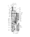
以下、図面を参照して本発明の好適な実施形態について説明する。先ず、図1乃至図2を参照して実施形態に係るパチンコ機の全体構成について説明する。図1は、パチンコ機を示す正面図である。図2は、本体枠及び前面枠を開放した状態のパチンコ機を示す斜視図である。   Hereinafter, preferred embodiments of the present invention will be described with reference to the drawings. First, the overall configuration of the pachinko machine according to the embodiment will be described with reference to FIGS. 1 and 2. FIG. 1 is a front view showing a pachinko machine. FIG. 2 is a perspective view showing the pachinko machine with the main body frame and the front frame opened.

図1に示すように、遊技機としてのパチンコ機1は、外枠2、本体枠3、遊技盤4、前面枠5等を備えて構成されている。外枠2は、上下左右の枠材によって縦長四角形の枠状に形成され、外枠2の前側下部には、本体枠3の下面を受ける下受板6を有している。外枠2の前面一側には、ヒンジ機構7によって本体枠3が前方に開閉可能に装着されている。また、本体枠3は、前枠体8、遊技盤装着枠9、及び機構装着枠10を合成樹脂材によって一体成形することで構成されている。本体枠3の前側に形成された前枠体8は、外枠2前側の下受板6を除く外郭形状に対応する大きさの矩形枠状に形成されている。なお、本実施形態では、パチンコ機1の正面を視認する視線方向を前側(前面側)とし、これとは反対側(例えば、前枠体8に対する本体枠3側)を後側(背面側)とする。   As shown in FIG. 1, a pachinko machine 1 as a gaming machine includes an outer frame 2, a main body frame 3, a game board 4, a front frame 5, and the like. The outer frame 2 is formed in a vertically rectangular frame shape by upper, lower, left and right frame members, and has a lower plate 6 that receives the lower surface of the main body frame 3 at the lower front side of the outer frame 2. A main body frame 3 is attached to the front side of the outer frame 2 by a hinge mechanism 7 so as to be opened and closed forward. The main body frame 3 is formed by integrally molding the front frame body 8, the game board mounting frame 9, and the mechanism mounting frame 10 with a synthetic resin material. The front frame 8 formed on the front side of the main body frame 3 is formed in a rectangular frame shape having a size corresponding to the outer shape excluding the support plate 6 on the front side of the outer frame 2. In this embodiment, the line-of-sight direction in which the front of the pachinko machine 1 is viewed is the front side (front side), and the opposite side (for example, the main body frame 3 side with respect to the front frame body 8) is the rear side (back side). And

また、本体枠3は、合成樹脂材によって一体に形成されると共に、前面側に遊技盤装着枠9が背面側に機構装着枠10がそれぞれ形成されている。これによって、合成樹脂製の本体枠3は、従来の前枠(内枠、前面枠等と呼ばれることがある)と、機構板(裏機構板、裏セット板等と呼ばれることがある)との機能を兼ね備えている。   The main body frame 3 is integrally formed of a synthetic resin material, and a game board mounting frame 9 is formed on the front side, and a mechanism mounting frame 10 is formed on the back side. As a result, the synthetic resin main body frame 3 includes a conventional front frame (sometimes called an inner frame, a front frame, etc.) and a mechanism plate (sometimes called a back mechanism plate, a back set plate, etc.). It has a function.

前枠体8の後部に一体的に形成された遊技盤装着枠9には、遊技盤4が前方から着脱交換可能に装着されるようになっている。また、遊技盤装着枠9の左側部には、係合突部9aが上下に2つ形成され、遊技盤装着枠9の右側部には、係合凹部(図示しない)が上下に2つ形成されている。また、遊技盤4の盤面(前面)の左側部には係合突部9aと対応する係止穴4e(図4参照)が上下に2つ形成され、遊技盤4の盤面の右側部には係合凹部と対応する係合フック4cが上下に2つ形成されている。係合フック4cは、遊技盤4と遊技盤装着枠9とを係脱可能に係止する。   A game board 4 is attached to the game board mounting frame 9 integrally formed at the rear part of the front frame body 8 so as to be detachable and replaceable from the front. In addition, two engaging protrusions 9 a are formed on the left side of the game board mounting frame 9, and two engagement recesses (not shown) are formed on the right side of the game board mounting frame 9. Has been. In addition, two engagement holes 4e (see FIG. 4) corresponding to the engagement protrusions 9a are formed on the left side of the board surface (front surface) of the game board 4, and the right side of the board surface of the game board 4 is formed on the right side of the game board 4. Two engaging hooks 4c corresponding to the engaging recesses are formed on the top and bottom. The engagement hook 4c detachably engages the game board 4 and the game board mounting frame 9 with each other.

さらに、遊技盤4の左下部には、係止フック9bが形成され、遊技盤装着枠9の左下部には係止フック9bと対応する付勢ロック部(図示しない)が設けられている。遊技盤4を遊技盤装着枠9に装着した場合には付勢ロック部が係止フック9bを下方に付勢して係止する。なお、付勢ロック部によって係止フック9bを下方に付勢することにより遊技盤4に下方への付勢力を作用しつつ係止することができる。これにより遊技盤4が遊技盤装着枠9の下縁部と密着して下方に押圧固定される。   Further, a locking hook 9b is formed in the lower left portion of the game board 4, and an urging lock portion (not shown) corresponding to the locking hook 9b is provided in the lower left portion of the game board mounting frame 9. When the game board 4 is mounted on the game board mounting frame 9, the urging lock portion urges the locking hook 9b downward to lock it. In addition, it is possible to lock the game board 4 while applying a downward biasing force by biasing the latching hook 9b downward by the biasing lock portion. As a result, the game board 4 comes into close contact with the lower edge of the game board mounting frame 9 and is pressed and fixed downward.

また、遊技盤4の盤面には、外レールと内レールとを備えた案内レール11が設けられている。また、遊技盤装着枠9よりも下方に位置する前枠体8の前側下部の一側寄りには、下部スピーカ14が装着されている。また、前枠体8前面の下部領域内の上側部分には、遊技盤4の発射通路に向けて遊技球を導く発射レール15が傾斜状に装着されている。一方、前枠体8前面の下部領域内の下側部分には、下前面部材16が装着されている。下前面部材16前面のほぼ中央には、下皿17が設けられ、片側寄りには操作ハンドル18が設けられている。   A guide rail 11 having an outer rail and an inner rail is provided on the surface of the game board 4. Further, a lower speaker 14 is attached to one side of the front lower portion of the front frame body 8 located below the game board mounting frame 9. A launch rail 15 that guides the game ball toward the launch path of the game board 4 is attached to the upper portion in the lower region of the front surface of the front frame 8 in an inclined manner. On the other hand, a lower front member 16 is attached to a lower portion in the lower area of the front surface of the front frame body 8. A lower pan 17 is provided substantially at the center of the front surface of the lower front member 16, and an operation handle 18 is provided closer to one side.

また、図2に示すように、本体枠3(前枠体8)のヒンジ機構7が設けられる側とは反対側となる開放側の後面には、外枠2に対して本体枠3を施錠する機能と、本体枠3に対して前面枠5を施錠する機能とを兼ね備えた施錠装置19が装着されている。施錠装置19は、外枠2に設けられた閉止具20に係脱可能に係合して本体枠3を閉鎖状態に施錠する上下複数の本体枠施錠フック21と、前面枠5の開放側の後面に設けられた閉止具22に係脱可能に係合して前面枠5を閉鎖状態に施錠する上下複数の扉施錠フック23とを備えている。   Further, as shown in FIG. 2, the main body frame 3 is locked to the outer frame 2 on the rear surface of the main body frame 3 (front frame body 8) opposite to the side on which the hinge mechanism 7 is provided. The locking device 19 having both the function to perform and the function to lock the front frame 5 to the main body frame 3 is mounted. The locking device 19 includes a plurality of upper and lower body frame locking hooks 21 that are detachably engaged with a closing tool 20 provided on the outer frame 2 to lock the main body frame 3 in a closed state, and an open side of the front frame 5. There are provided a plurality of upper and lower door locking hooks 23 that are detachably engaged with a closing tool 22 provided on the rear surface and lock the front frame 5 in a closed state.

しかして、シリンダー錠24の鍵穴に鍵が挿入されて一方向に回動操作されることで、本体枠施錠フック21と外枠2の閉止具20との係合が解除されて本体枠3が解錠され、これとは逆方向に鍵が回動操作されることで、扉施錠フック23と前面枠5の閉止具22との係合が解除されて前面枠5が解錠されるようになっている。なお、シリンダー錠24の前端部は、パチンコ機1の前方から鍵を挿入して解錠操作が行えるように、前枠体8及び下前面部材16を貫通して下前面部材16の前面に露出して配置されている。   Thus, when the key is inserted into the key hole of the cylinder lock 24 and rotated in one direction, the engagement between the main body frame locking hook 21 and the closing tool 20 of the outer frame 2 is released, and the main body frame 3 is moved. When unlocked and the key is rotated in the opposite direction, the engagement between the door locking hook 23 and the closing tool 22 of the front frame 5 is released, and the front frame 5 is unlocked. It has become. The front end of the cylinder lock 24 is exposed to the front surface of the lower front member 16 through the front frame body 8 and the lower front member 16 so that the unlocking operation can be performed by inserting a key from the front of the pachinko machine 1. Are arranged.

なお、本実施例では、時計回り方向に鍵を回動操作することで外枠2に対して本体枠3が解錠され、反時計回り方向に鍵を解錠操作することで本体枠3に対して前面枠5が解錠される。このように、回動操作の方向を異ならせるだけで、本体枠3又は前面枠5のいずれかを解錠させることができる。また、施錠装置19は、本体枠3を閉塞状態に施錠したときに、鍵以外の外部操作によって本体枠施錠フック21と外枠2の閉止具20との係合が解除されないように本体枠施錠フック21をロックするロック機構をさらに備えている。しかして、本体枠3を閉塞状態に施錠したときには、ロック機構により本体枠施錠フック21がロックされる。また、本体枠施錠フック21よりも外枠2と本体枠3(前面枠8)との間隙に近い側(図2において右側方)にリブが突設形成され、当該リブにより本体枠施錠フック21が外枠2と本体枠3(前面枠8)との間隙から針金等を差し込んで直接本体枠施錠フック21を操作しようとしてもリブに当接する。従って、外枠2と本体枠3(前面枠3)との間隙から針金等により本体枠3を不正に解錠する不正行為を防止することができる。   In the present embodiment, the main body frame 3 is unlocked with respect to the outer frame 2 by rotating the key clockwise, and the main body frame 3 is unlocked by operating the key counterclockwise. On the other hand, the front frame 5 is unlocked. Thus, either the main body frame 3 or the front frame 5 can be unlocked only by changing the direction of the rotation operation. The locking device 19 also locks the main body frame 3 so that the engagement between the main body frame locking hook 21 and the closing tool 20 of the outer frame 2 is not released by an external operation other than the key when the main body frame 3 is locked in the closed state. A lock mechanism for locking the hook 21 is further provided. Thus, when the main body frame 3 is locked in the closed state, the main body frame locking hook 21 is locked by the lock mechanism. Further, a rib is formed so as to project from the side closer to the gap between the outer frame 2 and the main body frame 3 (front frame 8) than the main body frame locking hook 21 (right side in FIG. 2). However, even if an attempt is made to directly operate the main body frame locking hook 21 by inserting a wire or the like from the gap between the outer frame 2 and the main body frame 3 (front frame 8), the rib contacts the rib. Accordingly, it is possible to prevent an illegal act of illegally unlocking the main body frame 3 with a wire or the like from the gap between the outer frame 2 and the main body frame 3 (front frame 3).

本体枠3前面の一側には、ヒンジ機構25によって前面枠5が前方に開閉可能に装着されている。前面枠5は、扉本体フレーム26、上皿28、及び操作ボタン18a(操作手段)を備えて構成されている。扉本体フレーム26は、プレス加工された金属製フレーム部材によって構成され、前枠体8の上端から下前面部材16の上縁に亘る部分を覆う大きさに形成されている。扉本体フレーム26のほぼ中央には、後述する遊技盤4の遊技領域12を前方から透視可能なほぼ円形状の開口窓30が形成されている。また、扉本体フレーム26の後側には、開口窓30よりも大きい矩形枠状をなす窓枠31が設けられ、該窓枠31には、透明板32が装着されている。   A front frame 5 is attached to one side of the front surface of the main body frame 3 by a hinge mechanism 25 so as to be opened and closed forward. The front frame 5 includes a door body frame 26, an upper plate 28, and operation buttons 18a (operation means). The door main body frame 26 is formed of a pressed metal frame member, and is formed to have a size that covers a portion extending from the upper end of the front frame body 8 to the upper edge of the lower front member 16. A substantially circular opening window 30 through which a game area 12 of a game board 4 (to be described later) can be seen through from the front is formed at substantially the center of the door body frame 26. Further, a window frame 31 having a rectangular frame shape larger than the opening window 30 is provided on the rear side of the door main body frame 26, and a transparent plate 32 is attached to the window frame 31.

なお、本実施例では、遊技盤4の下方にシリンダー錠24を配置し、遊技盤4の右方に配置された施錠装置19を薄型化することで、遊技盤4に形成された遊技領域12の面積を従来よりも拡大することができ、遊技者の視認に対する興趣を高めることができる。また、遊技領域12を拡大することで、遊技領域12の中央部分に後述する球誘導装飾体66が配置されても、該球誘導装飾体66の下方に配置された可変入賞装置に遊技球を誘導し難いとの印象を与えることがない。また、遊技領域12の拡大に合わせて前面枠8の開口窓30も拡大され、該前面枠8の剛性が低下することとなるが、上皿28を一体的に構成する前面枠8とすることで、前面枠8の剛性の低下を抑制している。   In this embodiment, the gaming area 12 formed on the game board 4 is formed by disposing the cylinder lock 24 below the game board 4 and thinning the locking device 19 arranged on the right side of the game board 4. The area of the player can be expanded more than before, and the interest for the player's visual recognition can be enhanced. Further, by enlarging the game area 12, even if a ball guide decoration body 66, which will be described later, is arranged at the center portion of the game area 12, the game ball is placed in the variable winning device arranged below the ball guide decoration body 66. There is no impression that it is difficult to guide. In addition, the opening window 30 of the front frame 8 is enlarged in accordance with the enlargement of the game area 12, and the rigidity of the front frame 8 is reduced. However, the front frame 8 that integrally forms the upper plate 28 is used. Thus, a decrease in the rigidity of the front frame 8 is suppressed.

扉本体フレーム26の前側には、開口窓30の周囲において、下部に上皿28が前面枠8と一体的に設けられ、左右両側部に枠ランプ27が、上部に上部スピーカ29が装着されている。また、上皿28の左片側寄りには、操作ボタン18aが配設され、上皿28の上面には、後述するメニュー表示画面で遊技者が操作するメニュー操作ボタン40が配置されている(図9参照)。なお、枠ランプ27は、後述する液晶表示器50(表示手段)にて実行される演出の演出態様に応じて点灯・消灯制御され、上部スピーカ29及び上述した下部スピーカ14は、液晶表示器50にて実行される演出の演出態様に応じて複数種類の音出力態様の音出力制御が実行される。このように、液晶表示器50にて実行される演出に同期して枠ランプ27の点灯・消灯制御、上部スピーカ29及び下部スピーカ14の音出力制御、を実行することにより演出効果を高め、遊技者の興趣を向上させるためのものである。また、上部スピーカ29及び下部スピーカ14では、不正行為が実行されたことを報知する警告音、遊技に関するエラー状態が発生したことを報知する情報音、等の出力も行われる。   On the front side of the door body frame 26, around the opening window 30, an upper plate 28 is provided integrally with the front frame 8 at the lower portion, frame lamps 27 are mounted on both left and right sides, and an upper speaker 29 is mounted on the upper portion. Yes. Further, an operation button 18a is disposed on the left side of the upper plate 28, and a menu operation button 40 operated by a player on a menu display screen described later is disposed on the upper surface of the upper plate 28 (see FIG. 9). Note that the frame lamp 27 is controlled to be turned on / off according to the effect mode of the effect executed by the liquid crystal display 50 (display means) described later, and the upper speaker 29 and the lower speaker 14 described above are the liquid crystal display 50. The sound output control of a plurality of types of sound output modes is executed in accordance with the effect mode of the effects executed in step S2. In this way, by performing the lighting / extinguishing control of the frame lamp 27 and the sound output control of the upper speaker 29 and the lower speaker 14 in synchronization with the effect executed on the liquid crystal display 50, the effect of the effect is enhanced, and the game It is intended to improve the interest of the elderly. The upper speaker 29 and the lower speaker 14 also output a warning sound for notifying that an illegal act has been executed, an information sound for notifying that an error state relating to a game has occurred, and the like.

次に、本体枠3の裏面構成について説明すると、図3に示すように、本体枠3の裏面上側には、遊技島に設置される球揚送装置から供給される遊技球を貯留する球タンク140と、球タンク140と払出装置109とを接続し、球タンクに貯留される遊技球を流下せしめるタンクレール141と、が配置されている。なお、タンクレール141によって球タンク140と接続される払出装置109(球払出手段)は、ユニット状に形成され、タンクレール141からの遊技球を受け入れて遊技球の払い出しを指示する信号に基づいて所定個数の遊技球を払い出す。   Next, the rear surface configuration of the main body frame 3 will be described. As shown in FIG. 3, a ball tank for storing game balls supplied from a ball lifting device installed on the game island is provided on the upper rear surface side of the main body frame 3. 140, a tank rail 141 that connects the ball tank 140 and the payout device 109 and allows the game balls stored in the ball tank to flow down, are arranged. The payout device 109 (ball payout means) connected to the ball tank 140 by the tank rail 141 is formed in a unit shape, and is based on a signal that receives a game ball from the tank rail 141 and instructs the payout of the game ball. Pay out a predetermined number of game balls.

また、タンクレール141の下方には、基板等が内蔵される基板保護カバー142が設けられている。なお、基板保護カバー142は、タンクレール141から落下した球によってこれら基板類が損傷するのを防止すると共に、各基板への不正行為を防止する役割を担っている。また、基板保護カバー142は、パチンコ機1の背面側に張り出しており、その下方に主制御基板201が配置されている。また、主制御基板201の遊技盤4背面側にはサブ統合基板211(図7参照)が配置されている。しかして、主制御基板201及びサブ統合基板211の上方がパチンコ機1の背面側に張り出した基板保護カバー142によって覆われ、タンクレール141から落下した球によって主制御基板201及びサブ統合基板211が損傷するのを防止している。   A substrate protective cover 142 in which a substrate and the like are built is provided below the tank rail 141. The substrate protection cover 142 plays a role of preventing these substrates from being damaged by a sphere dropped from the tank rail 141 and preventing illegal acts on each substrate. Further, the substrate protection cover 142 projects to the back side of the pachinko machine 1, and the main control substrate 201 is disposed below the substrate protection cover 142. Further, a sub-integrated board 211 (see FIG. 7) is arranged on the back side of the game board 4 of the main control board 201. Thus, the upper part of the main control board 201 and the sub integrated board 211 is covered by the board protective cover 142 projecting to the back side of the pachinko machine 1, and the main control board 201 and the sub integrated board 211 are separated by the spheres dropped from the tank rail 141. Prevents damage.

また、本体枠3の裏面下側一側に発射装置235(球発射手段)が取り付けられている。この発射装置235は、発射レール15に送られた球を発射する発射ハンマーと、発射ハンマーに往復回動動作を付与する発射モータ等を集約して設けることにより構成され、操作ハンドル18と関連付けられている。また、発射装置235の右側方には、払出基板205が設けられている。払出基板205は、主制御基板201からの遊技球の払い出しを指示する払出コマンドを受信したことに基づいて払出装置209を駆動制御する。   A launching device 235 (ball launching means) is attached to the lower side of the back surface of the main body frame 3. This launching device 235 is configured by integrating a launching hammer that launches a sphere sent to the launching rail 15 and a launching motor that imparts a reciprocating rotation to the launching hammer, and is associated with the operation handle 18. ing. Further, a payout substrate 205 is provided on the right side of the launching device 235. The payout board 205 drives and controls the payout device 209 based on the receipt of a payout command instructing payout of game balls from the main control board 201.

図4は、遊技盤4を単独で示している。遊技盤4は、その前面(盤面)にて遊技領域12を形成し、この遊技領域12内で遊技球を流下させながら遊技を進行させる役割を担う。通常、パチンコ機1における遊技は、遊技領域12内で遊技球が各種入賞口に入賞することに基づいて内部判定(大当り判定)が行われたり、あるいは賞球の払い出しが行われたりしながら進行する。   FIG. 4 shows the game board 4 alone. The game board 4 forms a game area 12 on the front surface (board face), and plays a role of advancing the game while flowing a game ball in the game area 12. Normally, a game in the pachinko machine 1 proceeds while making an internal determination (big hit determination) or paying out a winning ball based on the winning of gaming balls in various winning holes in the gaming area 12. To do.

遊技盤4は矩形状に成型された遊技板4aを有しており、遊技板4aの表面に円形状の遊技領域12が形成されている。また遊技板4aは、その前面が図示しないセル板を貼着することで装飾されており、さらに遊技領域12を取り囲む上下左右及び四隅はパネル装飾体4dによって装飾されている。パネル装飾体4dは装飾としての機能の他に、上記の案内レール11や係合フック4c等を支持する機能をも有している。またパネル装飾体4dの左側縁部には、遊技盤装着枠9の係合突部9aを係止させるため上下2つの係止穴4eが形成されている。   The game board 4 has a game board 4a molded in a rectangular shape, and a circular game area 12 is formed on the surface of the game board 4a. The game board 4a is decorated by attaching a cell board (not shown) on the front surface, and the upper, lower, left, and right and the four corners surrounding the game area 12 are decorated by a panel decoration body 4d. The panel decorative body 4d has a function of supporting the guide rail 11, the engagement hook 4c, and the like in addition to the function as a decoration. Further, two upper and lower locking holes 4e are formed on the left edge of the panel decoration body 4d to lock the engagement protrusion 9a of the game board mounting frame 9.

遊技領域12には、遊技の進行に必要な各種構成要素の他に、演出用の各種構成要素が配置されている。即ち、遊技領域12には多数の傷害釘や風車(図示しない)が適宜の配列で設置されており、発射された遊技球は傷害釘や風車等に誘導されながら遊技領域12内を流下する。また遊技領域12の中央部分から上半分には、ひときわ大きく目を引く球誘導装飾体66が配置されている。球誘導装飾体66は遊技板4aの表面(盤面)から前面側に突出して配置されており、その上縁部及び左右側縁部に沿って遊技球を案内することで、遊技球の流下方向に変化を与えることができる。なお、球誘導装飾体66についてはさらに後述する。   In the game area 12, in addition to various components necessary for the progress of the game, various components for production are arranged. That is, a large number of injury nails and windmills (not shown) are installed in the game area 12 in an appropriate arrangement, and the launched game balls flow down in the game area 12 while being guided by the injury nails and windmills. In addition, a ball guide decoration body 66 that is extremely eye-catching is arranged in the upper half from the central portion of the game area 12. The ball guiding decorative body 66 is disposed so as to protrude from the surface (board surface) of the game board 4a to the front surface side, and guides the game ball along the upper edge portion and the left and right edge portions thereof, thereby causing the game ball to flow downward. Can be changed. Note that the sphere guiding decorative body 66 will be further described later.

遊技領域12の下半分には、その中央に上始動口68(始動入賞口)及び下始動口70(始動入賞口)が上下に並んで配置されている。本実施形態では、下始動口70に電動チューリップ式の可変入賞装置が適用されており、下始動口70には、図中に実線で示されるように2つの可動片70aが左右に開いた状態にあるときだけ遊技球が入賞可能となる。   In the lower half of the game area 12, an upper start opening 68 (start winning prize opening) and a lower start opening 70 (start winning prize opening) are arranged vertically in the center. In the present embodiment, an electric tulip type variable winning device is applied to the lower start opening 70, and two movable pieces 70a are opened to the left and right as shown by solid lines in the drawing. The game ball can be won only when

また遊技領域12の下部分には、下始動口70よりも下方に大入賞口72(大入賞口装置)が設置されている。本実施形態では、大入賞口72に前後開閉式の条件作動装置が適用されており、大入賞口72には、図示のように開閉部材72aが前面側へ開いた状態にあるときだけ遊技球が入賞可能となる。   In the lower part of the game area 12, a big prize opening 72 (large prize opening device) is installed below the lower start opening 70. In this embodiment, a front / rear open / close condition operating device is applied to the special winning opening 72, and the special winning opening 72 has a game ball only when the opening / closing member 72a is open to the front side as shown in the figure. Can win.

その他、遊技領域12の下部分には、左右で一対をなすように2つの通過ゲート74が配置されている。また、遊技領域12の下部分には、大入賞口72の両側に2つずつ普通入賞口76(一般入賞口)が設置されており、これら4つの普通入賞口76は、遊技領域12の下縁部に沿って円弧を描くようにして配置されている。   In addition, two passing gates 74 are arranged in the lower portion of the game area 12 so as to form a pair on the left and right. In the lower part of the game area 12, two normal winning openings 76 (general winning openings) are provided on both sides of the big winning opening 72, and these four normal winning openings 76 are located under the gaming area 12. It arrange | positions so that an arc may be drawn along an edge.

球誘導装飾体66は全体として横長の額縁状に成型されており、その内側部分が中空となっている。前面側からみて、球誘導装飾体66の内側部分は演出領域(画像の表示や可動体の動作等の演出が行われる領域)として構成されており、球誘導装飾体66は演出領域の周囲を装飾するように配置されている。なお、演出領域や表示装置(液晶表示ユニット)、可動体等については後述する。   The ball guiding decorative body 66 is molded in a horizontally long frame shape as a whole, and its inner part is hollow. When viewed from the front side, the inner part of the ball guiding decorative body 66 is configured as an effect area (area where effects such as image display and movement of the movable body are performed), and the ball guiding decorative object 66 surrounds the effect area. Arranged to decorate. The production area, the display device (liquid crystal display unit), the movable body, and the like will be described later.

球誘導装飾体66には、全体としてパチンコ機1の機種ないしそのゲームコンセプトに基づくデザインが施されている。具体的には、先ず球誘導装飾体66の上縁部に目をやると、その中央位置に宝石状の頂部装飾体66aが配置されている。この頂部装飾体66aは、多面体カットが施された紫水晶(アメジスト)を象ったものであり、その周囲には宝石を支える金台を象った上部装飾体66bが配置されている。上部装飾体66bには微細な立体紋様が形成されており、その表面には光沢のあるクロムめっきが施されている。このため上部装飾体66bは、その微細な造形と金属的な光沢によって、宝石としての頂部装飾体66aを視覚的に引き立てている。   The ball guiding ornament 66 is generally designed based on the model of the pachinko machine 1 or its game concept. Specifically, when an eye is first placed on the upper edge portion of the ball guiding decorative body 66, a jewel-like top decorative body 66a is disposed at the center position. The top decorative body 66a is shaped like a purple crystal (amethyst) that has been cut into polyhedrons, and an upper decorative body 66b shaped like a metal base that supports jewelry is arranged around the top decorative body 66a. A fine three-dimensional pattern is formed on the upper decorative body 66b, and the surface thereof is subjected to glossy chrome plating. For this reason, the upper decorative body 66b visually enhances the top decorative body 66a as a gemstone by its fine modeling and metallic luster.

また球誘導装飾体66の左右の両側縁部には、左右で対をなすようにサイド装飾体66cが配置されている。これらサイド装飾体66cは架空動物(中国古代の瑞鳥)である「鳳凰」を象ったものであり、これら左右のサイド装飾体66cは、まさに「鳳凰」がこれから上空へ向かって飛翔しようとする姿を躍動的に表現したものとなっている。左右のサイド装飾体66cの表面には金めっき加工が施されており、その金色の光沢が視覚的に豪華で神秘的な雰囲気を醸し出している。   Further, side decorative bodies 66c are arranged on the left and right side edges of the ball guiding decorative body 66 so as to make a pair on the left and right. These side decorations 66c are modeled after "flies", which are fictitious animals (Chinese ancient ruins of birds). It is a dynamic expression of the figure to do. The surfaces of the left and right side decorative bodies 66c are gold-plated, and the golden luster creates a visually luxurious and mysterious atmosphere.

球誘導装飾体66の内縁(内周部分)には、上縁部から左右の内縁部及び下縁部にかけて長く延びた内縁装飾体66dが配置されている。これら内縁装飾体66dは、中央位置の上部装飾体66bの両側から左右の斜め下方に延びた後、奥側へ湾曲するようにして成形されており、そして左右の内縁部の上端位置から下端位置を通り、さらに下縁部まで延びている。図4ではサイド装飾体66cの背後に隠れているが、内縁装飾体66dは左右の内縁部にて保護板120の前面に近接した位置を下方に延び、そして、下方に向かうにつれてサイド装飾体66cの後方から前方へせり出してくるように湾曲している。さらに左右の内縁装飾体66dは、サイド装飾体66cの下端(「鳳凰」の尾の先端に相当する部分)の近傍から下縁部の前面側に露出し、そのまま下縁部の前面を中央付近まで延びている。これら左右の内縁装飾体66dもまた、上部装飾体66bと同様にクロムめっき加工が施されており、このため左右の内縁装飾体66dには上部装飾体66bとの視覚的な一体感が生じ、遊技者からは、あたかも上部装飾体66bと左右の内縁装飾体66dが一続きに成形されているかのように視認される。   An inner edge decoration body 66d extending from the upper edge portion to the left and right inner edge portions and the lower edge portion is disposed on the inner edge (inner peripheral portion) of the ball guide decoration body 66. These inner edge decorations 66d are formed so as to extend diagonally downward on the left and right from both sides of the upper decoration body 66b at the central position, and then bend to the back, and from the upper end position to the lower end position of the left and right inner edge parts. And further extends to the lower edge. Although hidden behind the side decorative body 66c in FIG. 4, the inner edge decorative body 66d extends downward at a position close to the front surface of the protective plate 120 at the left and right inner edge portions, and as it goes downward, the side decorative body 66c. It curves so that it protrudes from the back to the front. Furthermore, the left and right inner edge decorative bodies 66d are exposed from the vicinity of the lower end of the side decorative body 66c (the portion corresponding to the tip of the tail of the “鳳凰”) to the front side of the lower edge portion, and the front surface of the lower edge portion is left in the vicinity of the center. It extends to. The left and right inner edge decorative bodies 66d are also chrome-plated in the same manner as the upper decorative body 66b. Therefore, the left and right inner edge decorative bodies 66d have a visual sense of unity with the upper decorative body 66b. It is visually recognized by the player as if the upper decorative body 66b and the left and right inner edge decorative bodies 66d are formed in a continuous manner.

また球誘導装飾体66の下縁部には、その内縁に沿って下部装飾体67が設置されている。この下部装飾体67は、球誘導装飾体66の下縁部と保護板120との間を塞ぐようにして配置されている。下部装飾体67には、全体として周縁装飾部材122(図5参照)とデザイン上の統一感がある造形が施されているほか、その中央付近には左右で対をなす羽根状の装飾部が形成されている。なお、下部装飾体67の表面にもクロムメッキ加工が施されている。   A lower decorative body 67 is installed along the inner edge of the lower edge portion of the ball guiding decorative body 66. The lower decorative body 67 is disposed so as to close the space between the lower edge of the ball guiding decorative body 66 and the protective plate 120. The lower decorative body 67 is generally shaped with the peripheral decorative member 122 (see FIG. 5) and has a unified design, and a feather-shaped decorative part that makes a pair on the left and right is provided near the center. Is formed. The surface of the lower decorative body 67 is also chrome plated.

一方、球誘導装飾体66の上縁部には、上部装飾体66bを中心として左右に広がる上縁装飾体66eが配置されている。この上縁装飾体66eは正面からみて横に並んだ2つ山形状をなしており、また全体としてある程度の奥行き(厚み)を有している。上縁装飾体66eの前面には、宝石を配列したような微細な立体的造形が施されており、その表面には全体的に金めっき加工が施されている。このため、上部装飾体66b及び内縁装飾体66dの金属的な光沢と、隣接する上縁装飾体66eの金色の光沢とがきらびやかなコントラストをなし、そこには視覚的な高級感やゴージャスな雰囲気が醸し出されている。   On the other hand, an upper edge decorative body 66e that extends from the upper decorative body 66b to the left and right is disposed at the upper edge of the ball guiding decorative body 66. The upper edge decoration body 66e has two mountain shapes arranged side by side when viewed from the front, and has a certain depth (thickness) as a whole. The front surface of the upper edge decoration body 66e is subjected to fine three-dimensional modeling such as jewels arranged, and the entire surface is gold-plated. Therefore, the metallic luster of the upper decorative body 66b and the inner edge decorative body 66d and the golden luster of the adjacent upper edge decorative body 66e have a brilliant contrast, and there is a visual luxury and a gorgeous atmosphere. Is born.

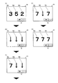
発光領域64a,64bは、中央の上部装飾体66bを中心として左右対称の位置に配列されている。このうち、上位に並んだ4つの発光領域64aは、パチンコ機1において特別図柄を表示するものとして機能する。特別図柄は、パチンコ機1において特別図柄判定(大当り判定)が行われ、その当落の結果が出たということを外部に向けて表示する情報(判定情報)となる。即ち、パチンコ機1における通常遊技状態(大当り遊技でない状態)で上始動口68又は下始動口70への入賞があると、それを契機に4つの発光領域67aがいろいろなパターンや発光色で点滅動作を開始し、これにより特別図柄の変動状態が表示される。このような特別図柄の変動開始(いわゆる「始動」)により、遊技者は大当り判定が行われたこと(あるいは、これから判定の結果が出ること)を認識することができる。この後、ある程度の時間が経過すると発光領域64aの点滅動作が停止し、そのときの判定結果(当落結果)を表示する態様で特別図柄が停止表示される。特別図柄の停止表示の態様について、簡易な例では4つの発光領域64aが全て同色で点灯していれば当選(大当り)を表し、4つの発光領域64aのいずれか1つでも点灯色が違っているか、もしくは消灯していれば落選を表すといった態様が挙げられる(但し、これら以外の態様もある。)。これにより、遊技者は大当り判定に当選したか否かを視覚的に認識することができる。   The light emitting areas 64a and 64b are arranged at symmetrical positions around the central upper decorative body 66b. Among these, the four light emitting areas 64a arranged in the upper rank function as displaying special symbols in the pachinko machine 1. The special symbol is information (determination information) that indicates to the outside that a special symbol determination (big hit determination) is performed in the pachinko machine 1 and that the winning result has come out. In other words, if there is a prize for the upper start port 68 or the lower start port 70 in the normal game state (non-hit game) in the pachinko machine 1, the four light emitting areas 67a blink in various patterns and light colors. The operation is started, and the variation state of the special symbol is displayed. With such a special symbol variation start (so-called “start”), the player can recognize that the jackpot determination has been performed (or that the determination result will be output from now on). Thereafter, when a certain amount of time has elapsed, the blinking operation of the light emitting area 64a is stopped, and the special symbol is stopped and displayed in such a manner that the determination result (winning result) at that time is displayed. With regard to the special symbol stop display mode, in a simple example, if all the four light emitting areas 64a are lit in the same color, it represents a win (big hit), and any one of the four light emitting areas 64a has a different lighting color. Or if it is turned off, it may indicate a loss (however, there are other modes as well). Thereby, the player can visually recognize whether or not the jackpot determination is won.

反対に、下位に並んだ4つの発光領域64bは、パチンコ機1において保留(始動記憶)ランプとして機能する。これら4つの発光領域64bは、そのとき発光(点灯)している個数によって特別図柄の始動記憶数(1〜4の保留球数)を表すことができる。具体的には、遊技中に上始動口68又は下始動口70への入賞があると、これを契機として特別図柄の始動条件が記憶され、この状態で特別図柄が変動表示中であれば、最も左に位置する発光領域64bが発光(点灯)して始動記憶数(保留球数)が1であることが表示される。一方、始動条件が記憶されている状態で、特別図柄が変動していなければ(変動状態から停止表示状態になった場合を含む)、記憶された始動条件に基づいて特別図柄の変動表示が開始される。この場合、始動条件の記憶は消去され、あわせて始動記憶数「1」に対応する発光領域64bの発光が停止(消灯)される。なお、本実施形態では始動記憶数(保留球数)の上限が4であるため、上限に達した場合、それ以上の始動条件は記憶されない。なお、上記の特別図柄及び始動記憶数の表示は、それぞれ特別図柄・保留表示LED基板144に実装された特別図柄表示LED144a及び特図始動記憶LED144bにより行われる。これら特別図柄表示LED144a及び特図始動記憶LED144bについては後述する。   On the other hand, the four light emitting areas 64b arranged in the lower layer function as a holding (starting memory) lamp in the pachinko machine 1. These four light emitting areas 64b can represent the number of stored special symbols (the number of reserved balls of 1 to 4) by the number of lights (lighted) at that time. Specifically, if there is a winning at the upper start opening 68 or the lower start opening 70 during the game, the start condition of the special symbol is stored as a trigger, and if the special symbol is in a variable display in this state, The leftmost light emitting area 64b emits light (lights up), and it is displayed that the starting memory number (the number of reserved balls) is one. On the other hand, if the special condition does not fluctuate in the state where the start condition is stored (including the case where the stop state is changed from the fluctuating state), the special symbol fluctuating display starts based on the stored start condition. Is done. In this case, the storage of the start condition is erased, and the light emission of the light emitting area 64b corresponding to the start storage number “1” is stopped (turned off). In the present embodiment, since the upper limit of the number of start memories (the number of held balls) is 4, when the upper limit is reached, no further start conditions are stored. The special symbol and the start memory number are displayed by the special symbol display LED 144a and the special symbol start memory LED 144b mounted on the special symbol / holding display LED substrate 144, respectively. The special symbol display LED 144a and the special symbol start memory LED 144b will be described later.

一方、球誘導装飾体66の上縁部には、上部装飾体66bと左右のサイド装飾体66cとの間をつなぐようにして左右の上隅装飾体66fが配置されている。また球誘導装飾体66の下縁部には、左右のサイド装飾体66cの下方にそれぞれ左右の下隅装飾体66gが配置されている。これら上隅装飾体66f及び下隅装飾体66gには、「鳳凰」にちなんだ「羽衣」を想起させる立体的な造形が施されており、その波打つような形状が「鳳凰」としてのサイド装飾体66cがこれからまさに飛翔しようとする姿を視覚的に強調している。また、上隅装飾体66f及び下隅装飾体66gはいずれも光透過性の半透明材料から成形されており、このうち左右の上隅装飾体66fでは、後述するセンター左部上LED基板104又はセンター右部上LED基板106による装飾的な発光動作が行われる。また、左右の下隅装飾体66gでは、後述するセンター左部下LED基板112又はセンター右部下LED基板114による装飾的な発光動作が行われる。   On the other hand, left and right upper corner decorative bodies 66f are arranged on the upper edge of the ball guiding decorative body 66 so as to connect the upper decorative body 66b and the left and right side decorative bodies 66c. In addition, left and right lower corner decoration bodies 66g are arranged below the left and right side decoration bodies 66c at the lower edge of the ball guide decoration body 66, respectively. The upper corner decorative body 66f and the lower corner decorative body 66g are three-dimensionally shaped to remind of a “hagoromo” named after “acupuncture”. 66c visually emphasizes that he is about to fly. Each of the upper corner decoration body 66f and the lower corner decoration body 66g is formed from a light-transmitting translucent material. Of these, the left and right upper corner decoration bodies 66f are the center left upper LED substrate 104 or the center described later. A decorative light emitting operation by the upper right LED board 106 is performed. In the lower left and right corner decoration bodies 66g, a decorative light emitting operation is performed by the center left lower LED board 112 or the center right lower LED board 114, which will be described later.

上記のように、球誘導装飾体66はその装飾的な造形やめっき加工によって視覚的な面白みを発揮したり、内蔵されたLEDを光源として各種の発光動作を行ったりする機能を有する。この他に球誘導装飾体66は、遊技領域12内で遊技球の流下を案内し、遊技球の動きに変化を与えることで遊技に面白みを付加する機能を有している。具体的には、球誘導装飾体66の両側縁部には、その内側にワープ通路66hが形成されており、また球誘導装飾体66の下縁部には、その上面にステージ部66iが形成されている。ワープ通路66hは球誘導装飾体66の左右両側から始まって両側縁部の内側を下り、そしてステージ部66iに通じている。さらに球誘導装飾体66の下縁部には、その中央位置に球放出口66jが形成されている。   As described above, the sphere guide decorative body 66 has a function of exhibiting visual interest by its decorative modeling and plating, and performing various light emission operations using the built-in LED as a light source. In addition, the ball guiding ornament 66 has a function of adding interest to the game by guiding the flow of the game ball within the game area 12 and changing the movement of the game ball. Specifically, warp passages 66h are formed inside both side edges of the ball guide decoration body 66, and a stage portion 66i is formed on the upper surface of the lower edge part of the ball guide decoration body 66. Has been. The warp passage 66h starts from the left and right sides of the ball guiding decorative body 66, descends from both side edges, and communicates with the stage portion 66i. Further, a ball discharge port 66j is formed at the center position of the lower edge portion of the ball guide decorative body 66.

ワープ通路66hは球誘導装飾体66の両側面にて開口しており、この開口を通じて内部に遊技球を受け入れ可能となっている。左右のワープ通路66hは、サイド装飾体66cの内部を僅かに中央方向に下りながら進むと、そこから奥側(後方)へ向けて折れ曲がり、そして真下方向に少し下った位置で中央方向に集まるようにして湾曲している。左右のワープ通路66hの下端はワープ出口として開口しており、開口から先はそのままステージ部66iにつながっている。また各ワープ通路66h内には、その途中に2つの突起部(図示しない)が段違いに形成されており、各ワープ通路66h内を流下する遊技球は、これら突起部に衝突しながら流下速度を緩和される。そして、遊技球がワープ通路66hの出口から放出されると、その先でステージ部66i上を転動する。   The warp passage 66h is opened on both side surfaces of the ball guiding decorative body 66, and the game ball can be received inside through the opening. The left and right warp passages 66h are bent toward the back side (rear) from the inside of the side decoration body 66c while descending slightly in the central direction, and gather in the central direction at a position slightly below in the downward direction. And curved. The lower ends of the left and right warp passages 66h are opened as warp outlets, and the ends from the openings are directly connected to the stage portion 66i. Further, in each warp passage 66h, two protrusions (not shown) are formed in the middle of the warp passage 66h, and a game ball flowing down in each warp passage 66h has a flow-down speed while colliding with these protrusions. Alleviated. Then, when the game ball is released from the exit of the warp passage 66h, it rolls on the stage portion 66i beyond that.

ステージ部66iは、左右のワープ通路66hの間を左右方向に長く延びており、その中央部分が僅かに盛り上がるようにして湾曲している。ステージ部66iの中央位置にはセンター窪み部(図示しない)が形成されており、このセンター窪み部は後方に向けて下り傾斜を有している。センター窪み部の奧で、下部装飾体67の中央位置に球落下穴67dが形成されており、球誘導装飾体66の下縁部には、球落下穴67dから下方に延びる球放出通路(図示しない)が形成されている。球放出通路は球落下穴67dから下方に下った後に前方へ折れ曲がり、そのまま下り傾斜を有したまま前面側の球放出口66jに通じている。   The stage portion 66i extends long in the left-right direction between the left and right warp passages 66h, and is curved so that the central portion is slightly raised. A center recess (not shown) is formed at the center of the stage portion 66i, and the center recess has a downward slope toward the rear. A ball drop hole 67d is formed at the center of the lower decorative body 67 at the bottom of the center depression, and a ball discharge passage (shown in the figure) extends downward from the ball drop hole 67d at the lower edge of the ball guide decorative body 66. Not) is formed. The ball discharge passage is bent forward after descending downward from the ball drop hole 67d, and communicates with the ball discharge port 66j on the front surface side while having a downward slope as it is.

左右のワープ通路66hからステージ部66iに放出された遊技球は、その上面にて左右方向に揺れながら転動する。このうち、中央のセンター窪み部に嵌り込んだ遊技球は、そこから球放出通路を経て、球放出口66jから下方に放出される。球放出口66jから放出された遊技球は、その真下位置にある上始動口68に向けて落下し、相当高い確率で上始動口68に入賞することができる。   The game ball released to the stage portion 66i from the left and right warp passages 66h rolls while swinging in the left-right direction on the upper surface. Among these, the game ball fitted in the central center depression is discharged downward from the ball discharge port 66j through the ball discharge passage. The game ball released from the ball discharge port 66j falls toward the upper start port 68 located immediately below it, and can win the upper start port 68 with a considerably high probability.

これに対し、ステージ部66iの上面にて、左右いずれかの窪み部67bに嵌り込んだ遊技球は、そこから球放出部67fに流下し、そして放出窪み部67cを経て球誘導装飾体66より下方の遊技領域12に落下する。放出窪み部67cはある程度の幅(遊技球が左右に転動できる幅)を有していることから、その落下方向は一定しておらず、あるものは上始動口68に入賞したり、あるものは上始動口68から左右に逸れて入賞しなかったりする。   On the other hand, on the upper surface of the stage portion 66i, the game ball fitted into the left or right hollow portion 67b flows down from there to the ball discharge portion 67f, and passes through the discharge hollow portion 67c from the ball guiding decorative body 66. It falls to the lower game area 12. Since the discharge depression 67c has a certain width (the width that allows the game ball to roll to the left and right), the direction of the drop is not constant, and some may win the upper start opening 68 Things deviate from the upper start 68 to the left and right and do not win.

なお本実施形態では、ステージ部66iや放出部67fは、いずれも遊技板4aの前面より奧、つまり開口部4fの内側に位置している。このため、遊技球が流下する遊技領域12は遊技板4aの表面から開口部4fの内側にまで広がっており、その分だけ遊技球の流下できる範囲が前後方向に拡張され、立体的で多様な遊技球の流下態様が実現されている。また、このように遊技領域12の範囲が開口部4fの内側にまで拡張されていても、本実施形態では保護板120によって遊技板4aより後方への遊技球の落下や飛び込みが確実に防止されている。   In the present embodiment, the stage portion 66i and the discharge portion 67f are both located on the heel from the front surface of the game board 4a, that is, inside the opening 4f. For this reason, the game area 12 where the game ball flows down extends from the surface of the game board 4a to the inside of the opening 4f, and the range in which the game ball can flow down is expanded in the front-rear direction, and is three-dimensional and diverse. The flow-down mode of the game ball is realized. In addition, even if the range of the game area 12 is expanded to the inside of the opening 4f as described above, in this embodiment, the protection plate 120 can reliably prevent the game ball from falling or jumping inward from the game plate 4a. ing.

可動体124は非作動時に左右で4つずつのグループに分かれ、遊技者から視認されない位置(遊技板4aの背後で開口部4fよりも下方の位置)に隠れて待機している。そして作動時に個々の可動体124はそれぞれ角度の異なる作動位置まで変位し、全体として扇を象るようにして配置される。なお、個々の可動体124の表面には「鳳凰の羽根」を象った緻密な造形が施されており、これにより球誘導装飾体66のデザインとの統一が図られている。   The movable body 124 is divided into four groups on the left and right when not in operation, and is hidden behind a position that is not visible to the player (a position below the opening 4f behind the game board 4a). In operation, the individual movable bodies 124 are displaced to operating positions at different angles, and are arranged so as to form a fan as a whole. The surface of each movable body 124 is densely modeled in the shape of a “wing of a spider”, thereby unifying the design of the ball guiding ornament 66.

この状態を遊技者の視点からみると、先ず最も手前側に球誘導装飾体66の装飾面(前面)が位置し、これより少し奧の位置に遊技球が左右方向に揺れ動くステージ部66iや内縁部の装飾面が位置し、次に保護板120を挟んで奧の空間部内に可動体124が位置し、そして可動体124よりもさらに奧に液晶表示ユニット150の表示画面が位置することになる。したがって、遊技者が最も奧の表示画面に視線を送るとき、その手前側に空間部や可動体124、保護板120、球誘導装飾体66の装飾面やステージ部66i等を視界の中に認めることとなり、これらの前後方向への重なりによって視覚的な奥行き感や立体感が強調される。   Looking at this state from the viewpoint of the player, the decoration surface (front surface) of the ball guide decoration body 66 is first positioned closest to the front side, and the stage portion 66i and the inner edge where the game ball swings in the left-right direction at a slightly lower position than this. The decorative surface of the portion is located, the movable body 124 is then located in the space portion of the bag with the protective plate 120 interposed therebetween, and the display screen of the liquid crystal display unit 150 is located further on the side of the movable body 124. . Accordingly, when the player sends his gaze to the most display screen, the space portion, the movable body 124, the protection plate 120, the decoration surface of the ball guiding ornament 66, the stage portion 66i, etc. are recognized in the field of view. In other words, the visual depth and stereoscopic effect are enhanced by the overlap in the front-rear direction.

球誘導装飾体66の他に、遊技領域12の下縁部には左右で対をなすサイド装飾部材82が設置されている。4つの普通入賞口76のうち、右上及び左上に位置する普通入賞口76はサイド装飾部材82と一体に形成されている。またサイド装飾部材82には、球誘導装飾体66のデザインコンセプトと統一感のあるデザインが施されている。なお本実施形態では、下始動口70を構成する可変入賞装置や、右下及び左下に位置する普通入賞口76にも装飾的な造形が施されており、そのデザインには球誘導装飾体66やサイド装飾部材82のデザインとの統一が図られている。   In addition to the ball guiding ornament 66, a side decoration member 82 that is paired on the left and right is installed on the lower edge of the game area 12. Of the four normal winning holes 76, the normal winning holes 76 positioned at the upper right and the upper left are formed integrally with the side decoration member 82. The side decorative member 82 has a design that is consistent with the design concept of the ball guiding decorative body 66. In the present embodiment, the variable winning device constituting the lower start opening 70 and the normal winning opening 76 located at the lower right and the lower left are also decoratively shaped, and the design thereof includes a ball guide decorative body 66. And the design of the side decoration member 82 are unified.

左側のサイド装飾体82の上部には、2つの発光領域82aと4つの発光領域82bとが左右方向に配列されている。このうち、右側に並んだ2つの発光領域82aは、パチンコ機1において普通図柄を表示するものとして機能する。普通図柄は、パチンコ機1において普通図柄判定が行われ、その当落の結果が出たということを外部に向けて表示する情報(判定情報)となる。また、左側に並んだ4つの発光領域82bは、パチンコ機1において普通図柄の保留(始動記憶)ランプとして機能する。これら4つの発光領域82bは、そのとき発光(点灯)している個数によって普通図柄の始動記憶数(1〜4の保留球数)を表すことができる。なお、上記の普通図柄及び始動記憶数の表示は、それぞれ普通図柄・保留表示LED基板146に実装された普通図柄表示LED146a及び普図始動記憶LED146bにより行われる。これら普通図柄表示LED146a及び普図始動記憶LED146bについては後述する。   Two light emitting regions 82a and four light emitting regions 82b are arranged in the left-right direction on the upper part of the left side decorative body 82. Among these, the two light emitting regions 82a arranged on the right side function as a normal symbol display in the pachinko machine 1. The normal symbol is information (determination information) that indicates to the outside that the normal symbol determination is performed in the pachinko machine 1 and the result of the winning is obtained. Further, the four light emitting regions 82b arranged on the left side function as a normal symbol holding (starting memory) lamp in the pachinko machine 1. These four light-emitting areas 82b can represent the number of stored normal symbols (the number of reserved balls of 1 to 4) according to the number of lights (lighted) at that time. The normal symbol and the start memory number are displayed by the normal symbol display LED 146a and the general symbol start memory LED 146b mounted on the normal symbol / holding display LED substrate 146, respectively. The normal symbol display LED 146a and the universal symbol start memory LED 146b will be described later.

また、右側のサイド装飾体82の上部には、2つの発光領域82cと4つの発光領域82dとが左右方向に配列されている。このうち、左側に並んだ2つの発光領域82cは、そのときいずれの発光領域82cが発光(点灯)しているかによって大当り遊技状態の種類に関する情報を表すことができる。また、右側に並んだ4つの発光領域82dは、そのときいずれの発光領域82dの組み合わせが発光(点灯)しているかによって確率変動状態中等の遊技状態に関する情報を表すことができる。なお、これら遊技状態の表示は、状態表示LED基板148に実装されたラウンド表示LED148a及び状態表示LED148bにより行われる。これらラウンド表示LED148a及び状態表示LED148bについても後述する。   In addition, two light emitting regions 82c and four light emitting regions 82d are arranged in the left-right direction above the right side decorative body 82. Among these, the two light emitting areas 82c arranged on the left side can represent information on the type of the big hit gaming state depending on which of the light emitting areas 82c is emitting (lighting) at that time. Also, the four light emitting areas 82d arranged on the right side can represent information on the gaming state such as in the probability variation state depending on which combination of the light emitting areas 82d emits light (lights up). The display of these game states is performed by the round display LED 148a and the state display LED 148b mounted on the state display LED substrate 148. These round display LEDs 148a and status display LEDs 148b will also be described later.

図5は、遊技盤4を構成部品に分けた状態で示している。上記のように、遊技板4aの前面には各種入賞口等の他に球誘導装飾体66やサイド装飾部材82等の装飾部品が取り付けられているが、遊技板4aには、これら装飾部品の取付位置にそれぞれ開口部4f,4gが形成されている。開口部4f,4gは遊技板4aを前後方向(厚み方向)に貫通して形成されており、このうち中央に大きく形成された開口部4fの開口縁形状は球誘導装飾体66の外形に対応し、また左右に対をなして形成された開口部4gの開口縁形状は左右のサイド装飾部材82の外形に対応している。球誘導装飾体66及び左右のサイド装飾部材82は、いずれも前面側から各開口部4f,4gに嵌め込んだ状態で遊技板4aに取り付けられる。   FIG. 5 shows the game board 4 divided into components. As described above, decorative parts such as the ball guiding decorative body 66 and the side decorative member 82 are attached to the front surface of the game board 4a in addition to various winning holes and the like. Openings 4f and 4g are formed at the mounting positions, respectively. The openings 4f and 4g are formed so as to penetrate the game board 4a in the front-rear direction (thickness direction), and the opening edge shape of the opening 4f formed large in the center corresponds to the outer shape of the ball guide decoration body 66. In addition, the opening edge shape of the opening 4g formed in a pair on the left and right corresponds to the outer shape of the left and right side decoration members 82. The ball guiding decorative body 66 and the left and right side decorative members 82 are both attached to the game board 4a in a state of being fitted into the openings 4f and 4g from the front side.

一方、遊技板4aの背面には大型の背面取付ユニット100が取り付けられている。この背面取付ユニット100は、遊技領域12内での演出動作に関する全ての電装品を1つに集合させたユニットとして構成されている。ここでいう演出動作には、例えば画像の表示や各種の発光動作、可動体の動作等が含まれる。本実施形態において、背面取付ユニット100は上記の球誘導装飾体66と共にパチンコ機1の演出動作を行う構成要素である。以下、本実施形態において球誘導装飾体66と背面取付ユニット100とを総称して演出装置(図中参照符号400)と呼ぶものとする。   On the other hand, a large back mounting unit 100 is attached to the back of the game board 4a. The back mounting unit 100 is configured as a unit in which all electrical components related to the rendering operation in the game area 12 are gathered together. The effect operation here includes, for example, image display, various light emission operations, operation of a movable body, and the like. In the present embodiment, the back mounting unit 100 is a component that performs the rendering operation of the pachinko machine 1 together with the above-described ball guiding ornament 66. Hereinafter, in this embodiment, the ball guidance decorative body 66 and the back surface mounting unit 100 will be collectively referred to as an effect device (reference numeral 400 in the figure).

演出装置400を構成する球誘導装飾体66は、遊技板4aの前面側から開口部4fに嵌め込むようにして取り付けられている。これに対し、演出装置400のもう1つの構成要素である背面取付ユニット100は、遊技板4aの背面側に取り付けられた状態で3つの開口部4f,4gを背面側から覆うだけの大きさを有している。即ち、背面取付ユニット100には、球誘導装飾体66において演出動作を行うために必要な電装品だけでなく、左右のサイド装飾部材82において演出動作(発光)を行うために必要な電装品が装備されている。   The ball guiding decorative body 66 constituting the effect device 400 is attached so as to be fitted into the opening 4f from the front side of the game board 4a. On the other hand, the rear mounting unit 100, which is another component of the effect device 400, is large enough to cover the three openings 4f and 4g from the rear side while being attached to the rear side of the game board 4a. Have. That is, the rear mounting unit 100 has not only electrical components necessary for performing the rendering operation in the ball guiding decorative body 66 but also electrical components necessary for performing the rendering operation (light emission) in the left and right side decoration members 82. Equipped.

背面取付ユニット100は大きく分けて2つのパーツから構成されており、具体的には上側のアッパーパーツ100a及び下側のロワーパーツ100bを有する。このうちアッパーパーツ100aは球誘導装飾体66に対応する電装品が組み込まれた部分であり、一方のロワーパーツ100bは左右のサイド装飾部材82に対応する電装品が組み込まれた部分となっている。   The rear mounting unit 100 is roughly divided into two parts, and specifically includes an upper part 100a on the upper side and a lower part 100b on the lower side. Of these, the upper part 100a is a part in which electric parts corresponding to the ball guiding ornament 66 are incorporated, and the lower part 100b is a part in which electric parts corresponding to the left and right side decoration members 82 are incorporated. .

アッパーパーツ100aは球誘導装飾体66の外形に合わせて横長の矩形に成型されており、その上縁部にセンター上LED基板102が設置されているほか、左右の上隅位置にそれぞれセンター左部上LED基板104、センター右部上LED基板106が設置されている。またアッパーパーツ100aの左右の側縁部には、それぞれセンター左部中LED基板108、センター右部中LED基板110が設置されている。さらにアッパーパーツ100aの左右の下隅部には、それぞれセンター左部下LED基板112、センター右部下LED基板114が設置されている。そしてアッパーパーツ100aの下縁部の中央位置には、センター下LED基板116が設置されている。これらLED基板は球誘導装飾体66の背後から前方又は側方に向けて光を発することで、球誘導装飾体66の発光領域を装飾的に発光させることができる。また、センター下LED基板116には、保護板120の後方で上向きに光を発するLEDが実装されており、これら上向きのLEDから発せられた光は、表示画面の前面側で可動体124を照射する。   The upper part 100a is formed in a horizontally long rectangle in accordance with the outer shape of the ball guide decoration body 66. The center upper LED board 102 is installed on the upper edge of the upper part 100a. The upper LED board 104 and the center right upper LED board 106 are installed. Further, the center left middle LED board 108 and the center right middle LED board 110 are respectively installed on the left and right side edges of the upper part 100a. Furthermore, a center left lower LED board 112 and a center right lower LED board 114 are installed at the left and right lower corners of the upper part 100a, respectively. A center lower LED substrate 116 is installed at the center position of the lower edge of the upper part 100a. These LED boards emit light from the back of the sphere guiding decorative body 66 toward the front or the side, so that the light emitting area of the sphere guiding decorative body 66 can be lit in a decorative manner. The center lower LED substrate 116 is mounted with LEDs that emit light upward behind the protective plate 120, and the light emitted from these upward LEDs irradiates the movable body 124 on the front side of the display screen. To do.

アッパーパーツ100aの中央位置には、透明な保護板120が設置されている。保護板120は横長の矩形状をなし、アッパーパーツ100aに対してその前面側から嵌め込むようにして取り付けられている。上記のセンター左部下LED基板112やセンター右部下LED基板114、センター下LED基板116は、アッパーパーツ100a内にて保護板120の背面側に設置されている。また、センター左部上LED基板104及びセンター右部上LED基板106は、その下側の一部分が保護板120の背面側に位置している。   A transparent protective plate 120 is installed at the center position of the upper part 100a. The protection plate 120 has a horizontally long rectangular shape, and is attached to the upper part 100a so as to be fitted from the front side. The center left lower LED board 112, the center right lower LED board 114, and the center lower LED board 116 are installed on the back side of the protective plate 120 in the upper part 100a. Further, the center left upper LED board 104 and the center right upper LED board 106 are partially located on the back side of the protective plate 120.

なお、左右側縁部に位置するセンター左部中LED基板108及びセンター右部中LED基板110は保護板120の両外側にあり、それぞれの実装面が保護板120に対して垂直となる姿勢でアッパーパーツ100aに取り付けられている。この状態で、センター左部中LED基板108及びセンター右部中LED基板110に実装されているLEDが互いに中央を向き合うようにして位置付けられている。また、これらLEDから発せられた光は、その一部がエッジライトとして保護板120の両側端面から保護板120の透明材料に導入され、内部を全反射しながら導かれる。このため本実施形態では、透明な保護板120が導光板としての機能をも有している。   It should be noted that the center left middle LED board 108 and the center right middle LED board 110 located at the left and right side edges are on both outer sides of the protective plate 120, and the mounting surfaces thereof are perpendicular to the protective plate 120. It is attached to the upper part 100a. In this state, the LEDs mounted on the center left middle LED board 108 and the center right middle LED board 110 are positioned so that the centers face each other. A part of the light emitted from these LEDs is introduced into the transparent material of the protective plate 120 from both end faces of the protective plate 120 as an edge light, and is guided while being totally reflected inside. For this reason, in this embodiment, the transparent protective plate 120 also has a function as a light guide plate.

アッパーパーツ100aの内側には、保護板120よりも背後の位置に四角枠形状の周縁装飾部材122が設置されている。周縁装飾部材122は、保護板120の上下左右の周縁部に沿うようにして配置されており、前面側からは透明な保護板120を透過して視認可能である。   On the inner side of the upper part 100a, a rectangular frame-shaped peripheral decorative member 122 is installed at a position behind the protective plate 120. The peripheral decorative member 122 is disposed along the upper, lower, left and right peripheral portions of the protective plate 120 and is visible through the transparent protective plate 120 from the front side.

またアッパーパーツ100aの下縁部には、保護板120より背後の位置に左右の可動体124が設置されている。左右の可動体124は細長い板状部材から成型されており、アッパーパーツ100aの内側には、このような板状の可動体124が左右でそれぞれ前後方向に4枚ずつ重ね合わせられた状態で収容されている。なお左右の可動体124は中央位置から左右対称に斜め下方へ垂れ下がったような姿勢を保持している。   In addition, left and right movable bodies 124 are installed at positions behind the protective plate 120 at the lower edge of the upper part 100a. The left and right movable bodies 124 are molded from elongated plate-like members, and four such plate-like movable bodies 124 are accommodated inside the upper part 100a in a state where four each are laminated in the front-rear direction on the left and right. Has been. The left and right movable bodies 124 hold a posture that hangs obliquely downward from the central position in a symmetrical manner.

また、アッパーパーツ100aの下縁部には、保護板120の下方位置に可動体駆動部モータ126が設置されているほか、ギヤボックスからなる可動体駆動部128が設置されている。可動体駆動部モータ126は、可動体124を作動させる駆動源となり、また可動体駆動部128は、可動体駆動部モータ126の駆動力を各可動体124に伝達し、実際に可動体124を予め決められた態様で作動させる機能を有する。   In addition, a movable body driving unit motor 126 including a gear box is installed at the lower edge of the upper part 100a in addition to the movable body driving unit motor 126 at a position below the protective plate 120. The movable body drive unit motor 126 serves as a drive source for operating the movable body 124, and the movable body drive unit 128 transmits the driving force of the movable body drive unit motor 126 to each movable body 124, and actually moves the movable body 124. It has the function of operating in a predetermined manner.

また可動体駆動部128には、可動体モータセンサ234(図10に符号のみ記載)が内蔵されている。可動体モータセンサ234は透過式のフォトスイッチからなり、この可動体モータセンサ234により、可動体駆動部モータ126の作動時における可動体124の位置を検出可能となっている。   The movable body drive unit 128 incorporates a movable body motor sensor 234 (only the reference numeral is shown in FIG. 10). The movable body motor sensor 234 includes a transmissive photo switch, and the movable body motor sensor 234 can detect the position of the movable body 124 when the movable body driving unit motor 126 is operated.

もう一方のロワーパーツ100bは、ちょうどアッパーパーツ100aの下側にぶら下がるようにして連結されており、その全体的な外形がアルファベットのW字形状をなしている。即ち、ロワーパーツ100bの左右両側部分は上方へ拡開するようにして延びており、一方、左右両側部分の間をつなぐ連結部分は、その中央位置が僅かに上方へ山形に盛り上がっている。これにより、ロワーパーツ100bを全体としてみるとW字形状をなしていることがわかる。   The other lower part 100b is connected so as to hang just below the upper part 100a, and the overall outer shape thereof is an alphabetic W-shape. That is, the left and right side portions of the lower part 100b extend so as to expand upward, while the connecting portion that connects between the left and right side portions has a slightly raised central shape at the center. Accordingly, it can be seen that the lower part 100b as a whole has a W shape.

ロワーパーツ100bの左右両側部分には、それぞれサイドLED基板130が設置されている。これらサイドLED基板130は、左右のサイド装飾部材82の背後から前方に向けて光を発することで、各サイド装飾部材82の発光領域を装飾的に発光させることができる。   Side LED boards 130 are respectively installed on the left and right sides of the lower part 100b. These side LED boards 130 emit light from behind the left and right side decoration members 82 toward the front, so that the light emitting areas of the side decoration members 82 can be lit in a decorative manner.

本実施形態では、パチンコ機1において行われる内部判定(特別図柄判定、普通図柄判定等)に関する情報が多色又は単色のLEDを用いて表示されるものとなっており、そのための電装品として各種のLED基板が背面取付ユニット100に設置されている。   In the present embodiment, information relating to internal determination (special symbol determination, normal symbol determination, etc.) performed in the pachinko machine 1 is displayed using multi-color or single-color LEDs, and there are various electrical components for that purpose. The LED board is installed in the back mounting unit 100.

先ずアッパーパーツ100aの上縁部には、センター上LED基板102の後方に特別図柄・保留表示LED基板144(図10に符号のみ記載)が設置されている。この特別図柄・保留表示LED基板144には、4つの特図表示LED144a及び4つの特図始動記憶LED144bが実装されている。例えば、パチンコ機1において内部的な判定(大当りを決める判定)が行われると、これら特別図柄表示LED144aや特図始動記憶LED144bが決まったパターンで点灯又は点滅(あるいは消灯)し、判定に関する情報を表示するものとなっている。   First, on the upper edge of the upper part 100a, a special symbol / holding display LED substrate 144 (only the reference numeral is shown in FIG. 10) is installed behind the center LED substrate 102. On the special symbol / holding display LED substrate 144, four special figure display LEDs 144a and four special figure start storage LEDs 144b are mounted. For example, when an internal determination (determination to determine a big hit) is performed in the pachinko machine 1, the special symbol display LED 144a and the special diagram start storage LED 144b are turned on or blinking (or turned off) in a predetermined pattern, and information regarding the determination is displayed. It is to be displayed.

次に、ロワーパーツ100bの左側部分には、その上部位置に普通図柄・保留表示LED基板146が設置されている。この普通図柄・保留表示LED基板146には、2つの普図表示LED146a及び4つの普図始動記憶LED146bが実装されている。上記の大当り判定とはべつの普通図柄判定が行われると、普図表示LED146aや普図始動記憶LED146bが決まったパターンで点灯又は点滅(あるいは消灯)し、判定に関する情報を表示するものとなっている。   Next, a normal symbol / holding display LED board 146 is installed at the upper position of the left part of the lower part 100b. On the normal symbol / holding display LED substrate 146, two general symbol display LEDs 146a and four universal symbol start storage LEDs 146b are mounted. When the normal symbol determination is performed in addition to the above jackpot determination, the general diagram display LED 146a and the general diagram start memory LED 146b are turned on or blinking (or turned off) in a predetermined pattern, and information regarding the determination is displayed. Yes.

また、ロワーパーツ100bの右側部分には、その上部位置に状態表示LED基板148が設置されている。この状態表示LED基板148には、2つのラウンド表示LED148a及び4つの状態表示LED148bが実装されている。上記の大当り判定で当選し、大当りになるとラウンド表示LED148aや状態表示LED148bが決まったパターンで点灯又は点滅(あるいは消灯)し、大当り中や確率変動中等の遊技状態に関する情報を表示するものとなっている。   In addition, a status display LED board 148 is installed at the upper position of the right part of the lower part 100b. On this status display LED substrate 148, two round display LEDs 148a and four status display LEDs 148b are mounted. If the winning is determined by the jackpot determination and the jackpot is won, the round display LED 148a and the status display LED 148b are turned on or blinking (or turned off) in a predetermined pattern, and information regarding the gaming state such as during the jackpot or the probability change is displayed. Yes.

このように、本実施形態では演出装置400において各種の発光動作(装飾的な発光の他に、遊技者の利益に関わる判定情報の表示を含む)を行って遊技者の興趣を高めたり、遊技者の利益に関わる情報を提供したりしているが、特に本実施形態では、遊技板4aの前面側に取り付けられる球誘導装飾体66に多数の発光領域が設けられているにもかかわらず、その発光源となるLED基板は全て遊技板4aの背面側(背面取付ユニット100)に設けられている。このため、演出装置400の動作に必要なLED基板や電気配線を全て背面取付ユニット100に収容することができ、球誘導装飾体66にはLED基板や電気配線を別に設ける必要がない。   As described above, in the present embodiment, various effects of light emission (including display of determination information related to the player's interests in addition to decorative light emission) are performed in the rendering device 400 to enhance the player's interest, In particular, in the present embodiment, although the ball guide decorative body 66 attached to the front side of the game board 4a is provided with a large number of light emitting areas, All of the LED boards that serve as the light emission sources are provided on the back side (back mounting unit 100) of the game board 4a. For this reason, all the LED boards and electric wiring required for operation | movement of the production | presentation apparatus 400 can be accommodated in the back surface mounting unit 100, and it is not necessary to provide an LED board and electric wiring separately in the ball | bowl induction decoration body 66.

図6は、背面取付ユニット100を構成要素に分けた状態で示している。背面取付ユニット100には、アッパーパーツ100aの背面側に液晶表示ユニット150が組み付けられるものとなっている。液晶表示ユニット150は、表示制御基板220と液晶表示器(LCDモジュール)50とが一体化されて構成されており、表示制御基板220は、基板ボックス150aに収容された状態で液晶表示器50の背面に設置されている。また本実施形態では、基板ボックス150aの背面に放熱又は冷却用のファン150bが設置されている。   FIG. 6 shows the rear mounting unit 100 in a state where it is divided into components. In the back mounting unit 100, a liquid crystal display unit 150 is assembled on the back side of the upper part 100a. The liquid crystal display unit 150 is configured by integrating a display control board 220 and a liquid crystal display (LCD module) 50, and the display control board 220 is accommodated in the board box 150a in the state of the liquid crystal display 50. Installed on the back. In the present embodiment, a fan 150b for heat dissipation or cooling is installed on the back surface of the substrate box 150a.

ロワーパーツ100b(連結部分)の背面側にはパネル中継端子板151が設置されている。このパネル中継端子板151には、上記の特別図柄・保留表示LED基板144や普通図柄・保留表示LED基板146、状態表示LED基板148にそれぞれ対応するハーネスが1箇所に集合した状態で接続されており、各LED基板は、パネル中継端子板151を経由して主制御基板201に接続されるものとなっている。   A panel relay terminal plate 151 is installed on the back side of the lower part 100b (connection portion). The panel relay terminal board 151 is connected with harnesses corresponding to the special symbol / holding display LED substrate 144, the normal symbol / holding display LED substrate 146, and the status display LED substrate 148 in one place. Each LED board is connected to the main control board 201 via the panel relay terminal board 151.

液晶表示ユニット150を支持するため、アッパーパーツ100aの背面側には、その下縁部に受け部100cが形成されているほか、背面側からみて左側縁部に2つの係止部100dが形成されており、さらに右側縁部には上下スライド式のロック部材100eが設置されている。またアッパーパーツ100aの背面は、平坦な受け面として形成されており、液晶表示ユニット150がアッパーパーツ100aに対して背面側から組み付けられると、その受け面に液晶表示ユニット150の表示画面がぴったり密着する関係にある。また、合わせて周縁装飾部材122の後端が液晶表示ユニット150の前面に接触し、液晶表示ユニット150を受け止める受け部材としての機能を果たす。   In order to support the liquid crystal display unit 150, on the back side of the upper part 100a, a receiving portion 100c is formed at the lower edge portion thereof, and two locking portions 100d are formed at the left edge portion when viewed from the back side. Further, an up / down sliding lock member 100e is installed on the right edge. Further, the back surface of the upper part 100a is formed as a flat receiving surface, and when the liquid crystal display unit 150 is assembled to the upper part 100a from the back side, the display screen of the liquid crystal display unit 150 is closely attached to the receiving surface. Have a relationship. In addition, the rear end of the peripheral decorative member 122 contacts the front surface of the liquid crystal display unit 150 and functions as a receiving member that receives the liquid crystal display unit 150.

図6には示されていないが、基板ボックス150aの左側縁部には2つの係止部100dに対応して突起部が形成されており、液晶表示ユニット150がアッパーパーツ100aに組み付けられると、2つの係止部100dにそれぞれ突起部が入り込んだ状態で、液晶表示ユニット150がアッパーパーツ100aに係止される。また上下方向に関していえば、液晶表示ユニット150の下面はアッパーパーツ100aの受け部100cに支持され、その落下が防止されることになる。また、基板ボックス150aの右側縁部にはロック爪150cが形成されており、液晶表示ユニット150をアッパーパーツ100aの受け面に密着させた状態で上記のロック部材100eを上方へスライドさせると、ロック爪150cを介して液晶表示ユニット150がロックされ、これにより液晶表示ユニット150の後方への脱落が確実に防止される。本実施形態では、このようなロック爪150c及びロック部材100eを用いて液晶表示ユニット150を係止することにより、背面取付ユニット100に対して液晶表示ユニット150を容易に取り付けることができる。反対に、液晶表示ユニット150を取り外す際はロック部材100eの係止を解除するだけで容易に液晶表示ユニット150の取り外しが可能となる。これにより液晶表示ユニット150の着脱が容易となり、特にパチンコ機1の中でも高価な電装品である液晶表示ユニット150のリサイクルやリユースが容易となる。   Although not shown in FIG. 6, a protrusion is formed on the left edge of the substrate box 150a corresponding to the two locking portions 100d, and when the liquid crystal display unit 150 is assembled to the upper part 100a, The liquid crystal display unit 150 is locked to the upper part 100a in a state where the protrusions enter the two locking portions 100d. Further, regarding the vertical direction, the lower surface of the liquid crystal display unit 150 is supported by the receiving portion 100c of the upper part 100a, and its fall is prevented. A lock claw 150c is formed on the right edge of the substrate box 150a. When the liquid crystal display unit 150 is brought into close contact with the receiving surface of the upper part 100a, the lock member 100e is slid upward to lock the substrate box 150a. The liquid crystal display unit 150 is locked via the claw 150c, thereby reliably preventing the liquid crystal display unit 150 from falling backward. In the present embodiment, the liquid crystal display unit 150 can be easily attached to the rear surface mounting unit 100 by locking the liquid crystal display unit 150 using the lock claw 150c and the lock member 100e. On the other hand, when removing the liquid crystal display unit 150, the liquid crystal display unit 150 can be easily removed simply by releasing the locking of the lock member 100e. Accordingly, the liquid crystal display unit 150 can be easily attached and detached, and in particular, the liquid crystal display unit 150 which is an expensive electrical component in the pachinko machine 1 can be easily recycled and reused.

上記のように、背面取付ユニット100には各種LED基板をはじめ、可動体駆動部モータ126や液晶表示ユニット150等の演出動作に必要な全ての電装品が装備されているが、これら電装品につながる全ての電気配線(ハーネス類)は、背面取付ユニット100において1箇所にまとめた状態でサブ統合基板201に中継されている。即ち、背面取付ユニット100にはランプ駆動基板156が装備されており、演出動作を目的とした全ての電装品につながる電気配線は全てランプ駆動基板156に集められ、基板上の中継回路に接続される。なおランプ駆動基板156には、サブ統合基板211に接続するためのコネクタが実装されている。   As described above, the rear mounting unit 100 is equipped with all the electrical components necessary for rendering operations such as various LED boards, the movable body drive unit motor 126, the liquid crystal display unit 150, and the like. All the connected electrical wirings (harnesses) are relayed to the sub-integrated board 201 in a state where they are gathered in one place in the back mounting unit 100. That is, the rear mounting unit 100 is equipped with a lamp driving board 156, and all the electrical wirings connected to all the electrical components for the purpose of production operation are collected on the lamp driving board 156 and connected to a relay circuit on the board. The A connector for connecting to the sub-integrated board 211 is mounted on the lamp driving board 156.

ランプ駆動基板156は、開閉動作式の基板ケース158に収容された状態で背面取付ユニット100に取り付けられる。基板ケース158はアッパーパーツ100aの背面側にヒンジ158aを介して開閉式の基板ケース158が取り付けられており、このため基板ケース158は、背面取付ユニット100の背面側にて開閉可能となっている。また基板ケース158の上縁部に係止部158bが形成されており、これに対応してアッパーパーツ100aの上縁部に受け部100fが形成されている。図6に示される位置から基板ケース158をアッパーパーツ100aの背面に沿うようにして閉じると、係止部158bが受け部100fに差し込まれて係止される。これにより、基板ケース158が閉位置で係止されることになる。   The lamp driving substrate 156 is attached to the rear surface mounting unit 100 in a state where it is accommodated in an openable / closable substrate case 158. The board case 158 is provided with an openable / closable board case 158 via a hinge 158a on the back side of the upper part 100a. Therefore, the board case 158 can be opened and closed on the back side of the back mounting unit 100. . A locking portion 158b is formed at the upper edge of the substrate case 158, and a receiving portion 100f is formed at the upper edge of the upper part 100a correspondingly. When the substrate case 158 is closed from the position shown in FIG. 6 along the back surface of the upper part 100a, the locking portion 158b is inserted into the receiving portion 100f and locked. As a result, the substrate case 158 is locked in the closed position.

図6に示されているように、液晶表示ユニット150は、ランプ駆動基板156の基板ケース158を背面側へ開放させた状態で背面取付ユニット100から着脱可能となる。また、液晶表示ユニット150が組み付けられた状態で基板ケース158を閉位置に移動させると、ランプ駆動基板156は液晶表示ユニット150の背面に沿うようにして位置付けられる。なお、ここでいう「開閉」や「開放」、「閉位置」等は、いずれも本実施形態において基板ケース156の前後方向への動きを扉に見立てて表現したものである。厳密にいうと、基板ケース156そのものが何らかの開口や出入口を開閉しているわけではないが、ここでは直感的な理解を容易にするため便宜的に「開閉」等と表現している。以下の説明においても、基板ケース156や制御基板ボックス等の動きについて、扉に見立てた表現を適宜使用するものとする。   As shown in FIG. 6, the liquid crystal display unit 150 can be attached to and detached from the rear surface mounting unit 100 with the substrate case 158 of the lamp driving substrate 156 opened to the rear surface side. Further, when the substrate case 158 is moved to the closed position in a state where the liquid crystal display unit 150 is assembled, the lamp driving substrate 156 is positioned along the back surface of the liquid crystal display unit 150. Note that “opening / closing”, “opening”, “closed position”, and the like here are all expressed in the present embodiment as if the movement of the substrate case 156 in the front-rear direction is regarded as a door. Strictly speaking, the substrate case 156 itself does not open or close any opening or entrance / exit, but here it is expressed as “opening / closing” or the like for convenience in order to facilitate intuitive understanding. Also in the following description, expressions likened to doors are used as appropriate for the movement of the substrate case 156, the control substrate box, and the like.

図7は、遊技盤4の背面側における背面取付ユニット100の着脱を示している。図示のように、主制御基板ボックス201aと共にサブ統合基板ボックス211aを遊技板4aの後方へ回動させた状態では、後述する下裏誘導部材160の中央部分が大きく後方へ開放されている。したがって、この状態で背面取付ユニット100は単独で遊技板4aに対して容易に着脱可能となっている。   FIG. 7 shows the attachment / detachment of the back mounting unit 100 on the back side of the game board 4. As shown in the figure, in the state where the sub-integrated board box 211a is rotated to the rear of the game board 4a together with the main control board box 201a, the center portion of the lower back guiding member 160 described later is largely opened rearward. Therefore, in this state, the back mounting unit 100 can be easily attached to and detached from the game board 4a alone.

背面取付ユニット100とは別に遊技板4aの背面には、その下縁部の位置に下裏誘導部材160が設置されている。下裏誘導部材160は遊技板4aの幅寸法より僅かに短い横幅を有しており、その両側端部に形成された4本の挿入部160cが遊技板4aに差し込まれた状態で背面側からねじ止めにより固定されている。下裏誘導部材160には、全ての入賞口に入賞した遊技球を誘導するための全入賞球誘導通路160aが形成されており、この全入賞球誘導通路160aには、上記の上始動口68、下始動口70、大入賞口72、普通入賞口76に入賞した遊技球が落下して回収されるものとなっている。図7には詳しく示されていないが、全入賞球誘導通路160aは遊技板4aの背面に沿って幅方向に長く延びており、そして下裏誘導部材160の下端位置で下方に開放されている。なお、全入賞球誘導通路160aから下方に放出された遊技球は本体枠3に形成されている入賞球回収経路を通り、その後、球放出部(図3中、払出基板205の直ぐ下方に位置する)から島設備の回収経路に向けて放出される。   Apart from the back mounting unit 100, a lower back guide member 160 is installed on the back of the game board 4a at the position of the lower edge thereof. The lower back guide member 160 has a lateral width slightly shorter than the width dimension of the game board 4a, and the four insertion parts 160c formed on both side ends thereof are inserted into the game board 4a from the back side. It is fixed by screwing. The lower back guiding member 160 is formed with an all winning ball guiding passage 160a for guiding the game balls won in all winning ports. The all starting ball guiding passage 160a has the upper start opening 68 described above. The game balls won in the lower start opening 70, the big winning opening 72, and the normal winning opening 76 are dropped and collected. Although not shown in detail in FIG. 7, the all winning ball guiding passage 160a extends in the width direction along the back surface of the game board 4a, and is opened downward at the lower end position of the lower back guiding member 160. . Note that the game balls released downward from all the winning ball guide passages 160a pass through the winning ball collection path formed in the main body frame 3, and then, the ball discharge portion (positioned immediately below the payout board 205 in FIG. 3). To the collection route of island facilities.

上記のように遊技盤4の背面側には、主制御基板201と共にサブ統合基板211が設置されているが、これら主制御基板201及びサブ統合基板211は、いずれも対応する主制御基板ボックス201a又はサブ統合基板ボックス211aに収容されている。このうち主制御基板ボックス201aは、背面側からみて左側縁部が上下2箇所のヒンジ部80c(図7には上方1箇所のみ示されている)を介してサブ統合基板ボックス211aの背面側に回動自在に支持されている。   As described above, the sub-integrated board 211 is installed on the back side of the game board 4 together with the main control board 201. The main control board 201 and the sub-integrated board 211 are both corresponding main control board boxes 201a. Alternatively, it is accommodated in the sub-integrated board box 211a. Of these, the main control board box 201a is located on the back side of the sub-integrated board box 211a via the hinge part 80c (only one upper part is shown in FIG. 7) having two left and right edges when viewed from the back side. It is supported rotatably.

一方のサブ統合基板ボックス211aは、背面側からみて左側縁部が上下2箇所のヒンジ部162bを介して下裏誘導部材160に支持されている。このためサブ統合基板ボックス211aを後方へ開放すると、これと一緒に主制御基板ボックス201aが開放される。本実施形態では、サブ統合基板ボックス211aの右側縁部に係止部162cが形成されており、一方、下裏誘導部材160には係止部162cに対応する受け部160bが形成されている。このためサブ統合基板ボックス211aを遊技板4aの背面に向けて押し込むと、係止部162cが受け部160bに係止され、サブ統合基板ボックス211aが取付位置で固定される。また主制御基板ボックス201aの右側縁部にも係止部80dが形成されており、この係止部80dは、サブ統合基板ボックス211aの係止部162cに係止される。したがって、係止部80dの係止を解除することで、主制御基板ボックス201aがサブ統合基板ボックス211aに対して単独で開閉可能となっている。   One sub-integrated board box 211a is supported by the lower back guide member 160 via two hinge portions 162b on the left side when viewed from the back side. Therefore, when the sub-integrated board box 211a is opened rearward, the main control board box 201a is opened together with this. In the present embodiment, a locking portion 162c is formed on the right edge of the sub-integrated board box 211a, while a receiving portion 160b corresponding to the locking portion 162c is formed on the lower back guide member 160. Therefore, when the sub integrated board box 211a is pushed toward the back of the game board 4a, the locking part 162c is locked to the receiving part 160b, and the sub integrated board box 211a is fixed at the mounting position. Also, a locking portion 80d is formed at the right edge of the main control board box 201a, and the locking portion 80d is locked to the locking portion 162c of the sub-integrated board box 211a. Therefore, by releasing the locking of the locking portion 80d, the main control board box 201a can be opened and closed independently with respect to the sub integrated board box 211a.

下裏誘導部材160の下部には、左右の2箇所に突出部160d,160eが形成されている。これら突出部160d,160eは遊技板4aの後方へ向けて突出しており、このうち一方(図7でみて左側)の突出部160dは、サブ統合基板ボックス211aのヒンジ部162bを受ける部材として利用されている。本実施形態では、遊技盤4を単独で台上や床上に置いたとき、2箇所の突出部160d,160eが遊技盤4の後方で支えとなり、その後方への転倒を防止することができる。これにより、ホールでの盤替え作業時において、遊技盤4を台上や床上に仮置きしておく際の安定性が増し、作業性を向上することができる。なお、このとき突出部160d,160eと合わせてサブ統合基板ボックス212aや主制御基板ボックス201aを支えに利用してもよい。   At the lower part of the lower back guide member 160, protrusions 160d and 160e are formed at two places on the left and right. These projecting portions 160d and 160e project toward the rear of the game board 4a, and one of these projecting portions 160d (left side in FIG. 7) is used as a member for receiving the hinge portion 162b of the sub-integrated board box 211a. ing. In the present embodiment, when the game board 4 is placed alone on a table or on the floor, the two projecting portions 160d and 160e support the back of the game board 4 and can prevent the rearward fall. Thereby, the stability at the time of temporarily placing the game board 4 on the table or the floor at the time of the board change work in the hall is increased, and workability can be improved. At this time, the sub-integrated board box 212a and the main control board box 201a may be used as a support together with the protrusions 160d and 160e.

図8は、遊技板4aに取り付けられる各種構成要素の配置関係を示している。球誘導装飾体66は、遊技板4aの前面側から開口部4fに嵌め込まれた状態で遊技板4aの背面側にまで突出している。これにより遊技者は、遊技板4aの前面から奥行きDだけ入り込んだ位置まで球誘導装飾体66の立体的な装飾形状を視認することができるので、そこに視覚的な奥行きを感じることができる。   FIG. 8 shows an arrangement relationship of various components attached to the game board 4a. The ball guiding ornament 66 protrudes from the front side of the game board 4a to the back side of the game board 4a in a state of being fitted into the opening 4f. Thereby, the player can visually recognize the three-dimensional decorative shape of the ball guiding decorative body 66 from the front surface of the game board 4a to the position where only the depth D enters, so that the player can feel the visual depth there.

一方、背面取付ユニット100は遊技板4aの背面に取り付けられているが、球誘導装飾体66が遊技板4aの背面側に突出している分、上記の保護板120は遊技板4aの背面よりも後方に位置している。なお本実施形態では、背面取付ユニット100が取り付けられた状態で、保護板120の前面がちょうど球誘導装飾体66の後端面に接触するか、もしくは極めて近接する構造となっており、この位置で保護板120は遊技領域12内から後方への遊技球の落下を防止し、その背後にある可動体124や液晶表示ユニット150を保護している。   On the other hand, the back mounting unit 100 is attached to the back surface of the game board 4a. However, the protection plate 120 is more than the back surface of the game board 4a because the ball guiding decorative body 66 projects to the back side of the game board 4a. Located behind. In the present embodiment, the front surface of the protection plate 120 is in contact with or very close to the rear end surface of the ball guiding ornament 66 with the back surface mounting unit 100 mounted, and at this position. The protection plate 120 prevents the game ball from falling from the game area 12 to the rear, and protects the movable body 124 and the liquid crystal display unit 150 behind it.

また保護板120は、遊技板4aの後方で開口部4fの開口面積よりも大きい範囲に広がっているため、保護板120による開口部4fから後方への遊技球の飛び込み防止がより一層確実となる。   Further, since the protection plate 120 extends behind the game board 4a in a range larger than the opening area of the opening 4f, the protection plate 120 can further prevent the game ball from jumping in from the opening 4f to the rear. .

保護板120の前面側では、開口部4fの周囲が各種の装飾体(内縁装飾体66d,下部装飾体67等)によって縁取られており、一方、保護板120の後方では、周縁装飾部材122によって液晶表示ユニット150の表示画面が縁取りされているが、前後でこれら縁取りの大きさを比較すると、保護板120の前面側の縁取りに比較して、その後方の周縁装飾部材122による表示画面の縁取りの方が大きくなっている。このため、保護板120の後方で液晶表示ユニット150の表示画面サイズを開口部4fの開口面積よりも大きく確保することができ、それだけ迫力のある演出表示が可能となるし、表示画面の奥行き感が強調される。   On the front side of the protection plate 120, the periphery of the opening 4 f is bordered by various decorative bodies (inner edge decorative body 66 d, lower decorative body 67, etc.). The display screen of the liquid crystal display unit 150 is bordered. When the sizes of these borders are compared before and after, the border of the display screen by the peripheral decorative member 122 at the rear of the protective plate 120 is compared with the border on the front side of the protective plate 120. Is bigger. For this reason, the display screen size of the liquid crystal display unit 150 can be secured larger than the opening area of the opening 4f behind the protective plate 120, and a powerful effect display can be achieved. Is emphasized.

また液晶表示ユニット150は、保護板120の後方に間隔Sだけ離れた位置に設けられており、このため保護板120と液晶表示ユニット150の表示画面との間には、前後方向に厚み(間隔S)を有した空間部が形成されている。上記の可動体124はこの空間部内に配置されており、図示のように作動時の位置に変位した状態で、可動体124は液晶表示ユニット150の表示画面を部分的に覆っている。   Further, the liquid crystal display unit 150 is provided at a position separated from the protective plate 120 by a distance S, and therefore, a thickness (interval) in the front-rear direction is provided between the protective plate 120 and the display screen of the liquid crystal display unit 150. A space having S) is formed. The movable body 124 is disposed in the space, and the movable body 124 partially covers the display screen of the liquid crystal display unit 150 in a state where the movable body 124 is displaced to the position at the time of operation as illustrated.

図9は、上皿28の上面に配置されるメニュー操作ボタン40を示している。メニュー操作ボタン40は、「+」状に配置される上・下・左・右の各方向ボタン41a〜41dと、その右側方に配置される取消ボタン42及び決定ボタン43と、から構成されている。上方向ボタン41aは、メニュー表示画面においてカーソル位置を上方向に移動させるためのボタンである。下方向ボタン41bは、メニュー表示画面においてカーソル位置を下方向に移動させるためのボタンである。左方向ボタン41cは、メニュー表示画面においてカーソル位置を左方向に移動させるためのボタンである。右方向ボタン41dは、メニュー表示画面においてカーソル位置を右方向に移動させるためのボタンである。取消ボタン42は、メニュー表示画面においてカーソルが位置する事項を取り消すためのボタンである。決定ボタン43は、メニュー表示画面においてカーソルが位置する事項を決定するためのボタンである。なお、取消ボタン42及び決定ボタン43は、それぞれ上記したボタン機能以外にメニュー表示用のボタン機能を備えている。即ち、取消ボタン42及び決定ボタン43は、それぞれ特別図柄の変動表示が行われていない状態(サブ統合基板211の統合CPU212が主制御基板201から変動表示パターンコマンドを受信していない状態)で押圧操作されると、これに基づいて液晶表示器50にメニュー表示画面を表示させるようになっている。   FIG. 9 shows the menu operation buttons 40 arranged on the upper surface of the upper plate 28. The menu operation button 40 includes upper, lower, left, and right direction buttons 41a to 41d arranged in a “+” shape, and a cancel button 42 and a determination button 43 arranged on the right side thereof. Yes. The upward button 41a is a button for moving the cursor position upward on the menu display screen. The down button 41b is a button for moving the cursor position downward on the menu display screen. The left button 41c is a button for moving the cursor position to the left on the menu display screen. The right button 41d is a button for moving the cursor position to the right on the menu display screen. The cancel button 42 is a button for canceling the item where the cursor is positioned on the menu display screen. The determination button 43 is a button for determining an item where the cursor is positioned on the menu display screen. The cancel button 42 and the determination button 43 each have a button function for displaying a menu in addition to the above button functions. That is, the cancel button 42 and the determination button 43 are pressed in a state where the special symbol variation display is not performed (the integrated CPU 212 of the sub-integrated substrate 211 has not received the variation display pattern command from the main control substrate 201). When operated, the menu display screen is displayed on the liquid crystal display 50 based on this.

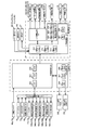
図10は、パチンコ機1の動作を制御するための構成を概略的に示している。パチンコ機1の制御は、大きく分けて主基板のグループと周辺基板のグループとで分担されており、このうち主基板のグループが遊技動作(入賞検出や当り判定、特別図柄表示、賞球払出等)を制御しており、周辺基板のグループが演出動作(発光装飾や音響出力、液晶表示等)を制御している。これら基板類は、いずれもパチンコ機1の背面側に設置されており、通常、本体枠3の施錠を解除した上で本体枠3を開放しない限り前面側から視認されたり、操作されたりすることはない。この他にも、パチンコ機1には電源基板や発射制御基板、インタフェース基板(CR機の場合)等が装備されているが、いずれも公知のものを適用できるため、ここでは図示と共に詳細な説明を省略する。   FIG. 10 schematically shows a configuration for controlling the operation of the pachinko machine 1. The control of the pachinko machine 1 is roughly divided into a main board group and a peripheral board group, and among these, the main board group plays game operations (winning detection, winning judgment, special symbol display, prize ball payout, etc.) ), And a group of peripheral boards controls production operations (light emission decoration, sound output, liquid crystal display, etc.). All of these boards are installed on the back side of the pachinko machine 1 and are normally visible or operated from the front side unless the main body frame 3 is opened after unlocking the main body frame 3. There is no. In addition to this, the pachinko machine 1 is equipped with a power supply board, a launch control board, an interface board (in the case of a CR machine), and the like. Is omitted.

主基板グループは、主制御基板201と払出基板205とから構成されている。主制御基板201は、中央演算装置としてのCPU202をはじめ、読み出し専用メモリとしてのROM203や読み書き可能メモリとしてのRAM204等を備えている。このうちCPU202は、ROM203に格納されている遊技制御プログラムを実行し、この実行に伴いパチンコ機1で行われる各種遊技を制御する。またCPU202は、周辺基板グループや払出基板205に送信するコマンド(演出コマンド、払出コマンド等)を作成する。また、RAM204には、主制御基板201で実行される種々の処理において生成される各種データや入力信号等の情報が一時的に記憶される。   The main board group includes a main control board 201 and a payout board 205. The main control board 201 includes a CPU 202 as a central processing unit, a ROM 203 as a read-only memory, a RAM 204 as a readable / writable memory, and the like. Among these, the CPU 202 executes a game control program stored in the ROM 203 and controls various games performed in the pachinko machine 1 in accordance with the execution. Further, the CPU 202 creates a command (such as an effect command and a payout command) to be transmitted to the peripheral board group and the payout board 205. Further, the RAM 204 temporarily stores information such as various data and input signals generated in various processes executed by the main control board 201.

なお、主制御基板201には、始動口スイッチ68a,70b(入賞検出手段)、ゲートスイッチ74a、カウントスイッチ72a、普通入賞口スイッチ76a等が接続されており、主制御基板201には、これらスイッチ類から検出信号が入力される。なお、始動口スイッチ68a,70bを除く全ての電装品(ゲートスイッチ74a、カウントスイッチ72a、普通入賞口スイッチ76a、ソレノイド71a,73a、特別図柄表示LED144a、特図始動記憶LED144b、普通図柄表示LED146a、普図始動記憶LED146b、ラウンド表示LED148a、状態表示LED148b)はパネル中継端子板151を介して主制御基板201に接続されている。   The main control board 201 is connected to start opening switches 68a and 70b (winning detection means), a gate switch 74a, a count switch 72a, a normal winning opening switch 76a, etc., and these switches are connected to the main control board 201. The detection signal is input from the class. All electrical components except the start port switches 68a and 70b (gate switch 74a, count switch 72a, normal winning port switch 76a, solenoids 71a and 73a, special symbol display LED 144a, special symbol start memory LED 144b, normal symbol display LED 146a, The normal start memory LED 146b, the round display LED 148a, and the status display LED 148b) are connected to the main control board 201 via the panel relay terminal board 151.

具体的には、ゲートスイッチ74aは遊技領域12内の通過ゲート74に対応して設置されており、遊技球が流下する過程で通過ゲート74を通過すると、その通過がゲートスイッチ74aにより検出され、そして検出信号がパネル中継端子板151を介して主制御基板201に入力される。また、始動口スイッチ68aは上始動口68に対応して設置されており、また始動口スイッチ70bは、下始動口70に対応して設置されている。したがって、遊技球が上始動口68又は下始動口70に入賞すると、対応する始動口スイッチ68a,70bから主制御基板201に検出信号が直接入力される。またカウントスイッチ72a(第1の入賞球検出手段)は大入賞口72に対応して設置されており、大当り遊技中に大入賞口72に遊技球が入賞すると、カウントスイッチ72aからパネル中継端子板151を介して主制御基板201に検出信号が入力される。そして、普通入賞口スイッチ76a(第2の入賞球検出手段)は普通入賞口76に対応して配置されており、遊技球が普通入賞口76に入賞すると、普通入賞口スイッチ76aからパネル中継端子板151を介して主制御基板201に検出信号が入力される。   Specifically, the gate switch 74a is installed corresponding to the passing gate 74 in the gaming area 12, and when the game ball passes through the passing gate 74 in the process of flowing down, the passage is detected by the gate switch 74a, A detection signal is input to the main control board 201 via the panel relay terminal board 151. The start port switch 68 a is installed corresponding to the upper start port 68, and the start port switch 70 b is installed corresponding to the lower start port 70. Therefore, when a game ball wins the upper start opening 68 or the lower start opening 70, a detection signal is directly input to the main control board 201 from the corresponding start opening switches 68a and 70b. The count switch 72a (first winning ball detecting means) is installed corresponding to the big winning hole 72, and when a game ball wins the big winning hole 72 during the big hit game, the count relay 72a is connected to the panel relay terminal board. A detection signal is input to the main control board 201 via 151. The normal winning opening switch 76a (second winning ball detecting means) is arranged corresponding to the normal winning opening 76, and when the game ball wins the normal winning opening 76, the normal winning opening switch 76a is connected to the panel relay terminal. A detection signal is input to the main control board 201 via the plate 151.

そして、CPU202は、これら入力された検出信号に応じた処理を実行する。即ちCPU202は、入力された検出信号に基づいてソレノイド71a,73a、特別図柄表示LED144a、特図始動記憶LED144b、普通図柄表示LED146a、普図始動記憶LED146b、ラウンド表示LED148a、状態表示LED148b等に対し、パネル中継端子板151を介してそれぞれの駆動信号を出力する。さらにCPU202は、入賞に応じた遊技球の払い出しを指示する払出コマンドを払出基板205に対して出力する。   Then, the CPU 202 executes processing according to these input detection signals. That is, the CPU 202 applies the solenoids 71a and 73a, the special symbol display LED 144a, the special symbol start storage LED 144b, the normal symbol display LED 146a, the general symbol start storage LED 146b, the round display LED 148a, the status display LED 148b and the like based on the input detection signal. Each drive signal is output via the panel relay terminal board 151. Furthermore, the CPU 202 outputs a payout command for instructing payout of the game ball according to the winning to the payout board 205.

払出基板205もまた、中央演算装置としての払出CPU206をはじめ読み出し専用メモリとしての払出ROM207や読み書き可能メモリとしての払出RAM208等を備えている。なお、上述した始動口スイッチ68a,70bやカウントスイッチ72a、普通入賞口スイッチ76a等により遊技球の入賞が検出されると、各スイッチから検出信号がパネル中継端子板151を介して主制御基板201に入力される。そして主制御基板201では、入力された検出信号に基づいてCPU202から払出基板205に対して規定個数の遊技球の払い出しを指示する払出コマンドが送信される。そして、払出基板205は、主制御基板201から受けとった払出コマンドを処理し、規定個数分の遊技球の払い出しを実行するべく払出装置209(払出モータ)に対して駆動信号を出力する。この結果、実際に払出装置209によって規定個数分の遊技球の払い出しが行われる。   The payout board 205 also includes a payout CPU 206 as a central processing unit, a payout ROM 207 as a read-only memory, a payout RAM 208 as a readable / writable memory, and the like. When a winning of a game ball is detected by the start port switches 68a, 70b, the count switch 72a, the normal winning port switch 76a, etc., a detection signal from each switch is sent to the main control board 201 via the panel relay terminal plate 151. Is input. In the main control board 201, a payout command for instructing the payout board 205 to pay out a specified number of game balls is transmitted from the CPU 202 to the payout board 205 based on the input detection signal. Then, the payout board 205 processes the payout command received from the main control board 201 and outputs a drive signal to the payout device 209 (payout motor) to execute payout of a specified number of game balls. As a result, the specified number of game balls are actually paid out by the payout device 209.

また払出基板205には、発射モータを備えた発射装置235が接続されており、発射装置235は、発射モータの動力を用いて遊技球を遊技領域12に向けて発射する動作を行うことができる。遊技者が操作ハンドル18を操作(捻り操作)すると、発射装置235の発射モータが駆動され、これにより遊技球が打ち出される。   Further, a launching device 235 having a launching motor is connected to the payout board 205, and the launching device 235 can perform an operation of launching a game ball toward the game area 12 using the power of the launching motor. . When the player operates the operation handle 18 (twisting operation), the firing motor of the launching device 235 is driven, and thereby a game ball is launched.

図10には示されてないが、発射装置235には、遊技者の身体が操作ハンドル18に触れていることを検知するためのタッチセンサが内蔵されている。発射装置235は、遊技者が操作ハンドル18に触れていることが検知されている場合に発射モータを駆動可能な状態となる。そして、この状態で操作ハンドル18が初期の位置から時計回り方向に捻り操作されると、発射装置235は実際に発射モータを駆動して遊技球を発射する。   Although not shown in FIG. 10, the launching device 235 incorporates a touch sensor for detecting that the player's body is touching the operation handle 18. The firing device 235 is in a state where the firing motor can be driven when it is detected that the player is touching the operation handle 18. In this state, when the operation handle 18 is twisted clockwise from the initial position, the launching device 235 actually drives the launch motor to launch the game ball.

あるいは、下皿17が満タン、つまり、払い出された遊技球で下皿17が満杯になったことを検出する下皿満タンスイッチを設け、この下皿満タンスイッチからの検出信号が入力されたときに操作ハンドル18の操作を受付不能な状態とする制御を行い、これにより発射装置235による発射モータの駆動を不可能な状態にすることもできる。即ち、払出装置209から払い出された遊技球はひとまず上皿28に貯留されるが、上皿28に貯留しきれない数の遊技球が払い出された場合には、その貯留しきれない分の遊技球は上皿28と連通した下皿17に貯留される。この状態でさらに払出装置209により遊技球が払い出され、いよいよ下皿17が満タンになると、上記の下皿満タンスイッチから検出信号が出力されるので、これにより操作ハンドル18の操作が受付不能な状態に制御される。またこの場合、下皿満タンスイッチからの検出信号が出力されなくなると、操作ハンドル18の操作を受付可能な状態に復帰する制御が行われる構成としてもよい。   Alternatively, a lower plate full tank switch is provided for detecting that the lower plate 17 is full, that is, the lower plate 17 is filled with paid out game balls, and a detection signal from the lower plate full tank switch is input. In this case, the operation of the operation handle 18 is controlled so as not to be accepted, and thus the driving of the firing motor by the firing device 235 can be made impossible. That is, the game balls paid out from the payout device 209 are temporarily stored in the upper plate 28. However, when a number of game balls that cannot be stored in the upper plate 28 are paid out, the game balls cannot be stored. Are stored in the lower plate 17 communicating with the upper plate 28. In this state, the game ball is paid out by the payout device 209, and when the lower plate 17 is finally full, a detection signal is output from the lower plate full tank switch, so that the operation of the operation handle 18 is accepted. Controlled to an impossible state. Further, in this case, when the detection signal from the lower pan full switch is not output, a control may be performed so that the operation handle 18 is returned to a state where the operation handle 18 can be accepted.

周辺基板グループは、サブ統合基板211やランプ駆動基板156、表示制御基板220等から構成されている。このうちサブ統合基板211は、統合CPU212(表示制御手段、操作検出手段)をはじめ統合ROM213、統合RAM214を備えている。また、サブ統合基板211は、音出力に関する制御を行う音源IC228を備えるほか、音出力に関する読み出し専用メモリとしての音ROM227をも備えている。統合CPU212は、統合ROM213に格納されている演出制御プログラムを実行することにより主制御基板201から受信された演出コマンドに基づく処理を実行する。また、統合RAM214には、サブ統合基板211で実行される種々の処理において生成される各種データや入出力信号、主制御基板201から受信された演出コマンド等の情報が一時的に記憶される。そして、統合CPU212は、RAM214に記憶されている演出コマンドを読み出すと、この読み出した演出コマンドに基づいて表示制御基板220に対して表示コマンドを送信したり、ランプ駆動基板156にランプ点灯信号や駆動信号を送信したり、あるいは、枠ランプ27に駆動信号を出力したりする。またサブ統合基板211は、音源IC228によって演出コマンドに基づく音出力態様を音ROM227から読み出し、この読み出した音出力態様に応じた駆動信号を上部スピーカ29及び下部スピーカ14に出力する。また、統合CPU212には、操作ボタン18a又はメニュー操作ボタン40(各方向ボタン41a〜41d、取消ボタン42、決定ボタン43)の操作に応じて操作信号が入力されたり、ランプ駆動基板156を介して可動体モータセンサ234の検出信号が入力されたりする。   The peripheral board group includes a sub-integrated board 211, a lamp driving board 156, a display control board 220, and the like. Of these, the sub-integrated board 211 includes an integrated CPU 212 (display control means, operation detection means), an integrated ROM 213, and an integrated RAM 214. The sub-integrated board 211 includes a sound source IC 228 that performs control related to sound output, and also includes a sound ROM 227 as a read-only memory related to sound output. The integrated CPU 212 executes a process based on the effect command received from the main control board 201 by executing the effect control program stored in the integrated ROM 213. In addition, the integrated RAM 214 temporarily stores various data and input / output signals generated in various processes executed by the sub-integrated board 211, information such as effect commands received from the main control board 201, and the like. Then, when the integrated CPU 212 reads the effect command stored in the RAM 214, the integrated CPU 212 transmits a display command to the display control board 220 based on the read effect command, or sends a lamp lighting signal or drive to the lamp drive board 156. A signal is transmitted, or a drive signal is output to the frame lamp 27. In addition, the sub-integrated board 211 reads a sound output mode based on the effect command by the sound source IC 228 from the sound ROM 227 and outputs a drive signal corresponding to the read sound output mode to the upper speaker 29 and the lower speaker 14. In addition, an operation signal is input to the integrated CPU 212 according to the operation of the operation button 18 a or the menu operation button 40 (the direction buttons 41 a to 41 d, the cancel button 42, and the determination button 43), or via the lamp driving board 156. A detection signal of the movable body motor sensor 234 is input.

ランプ駆動基板156は、サブ統合基板211から受信したランプ点灯信号をセンターLED基板102,104,106,108,110,112,114,116やサイドLED基板130に送信し、また、サブ統合基板211から受信した駆動信号を可動体駆動部モータ126に送信する。センターLED基板102,104,106,108,110,112,114,116やサイドLED基板130及び可動体駆動部モータ126は、演出装置400に装備されているものであり、このうちセンターLED基板102,104,106,108,110,112,114,116やサイドLED基板130は演出装置400において発光演出に用いられ、また可動体駆動部モータ126は、可動体124の駆動に用いられる。なお、ランプ駆動基板156は、サブ統合基板211から送信されるランプ点灯信号を各LED別に振り分けてLED基板に受け渡すほか、サブ統合基板211から送信される駆動信号を可動体駆動部モータ126にそのまま受け渡すものであり、実質的なLED基板及び可動体駆動部モータ126の制御はサブ統合基板211が行っている。以下、ランプ駆動基板156を省略して説明する場合がある。   The lamp driving board 156 transmits the lamp lighting signal received from the sub integrated board 211 to the center LED boards 102, 104, 106, 108, 110, 112, 114, 116 and the side LED board 130, and the sub integrated board 211. The drive signal received from is transmitted to the movable body drive unit motor 126. The center LED boards 102, 104, 106, 108, 110, 112, 114, 116, the side LED boards 130, and the movable body drive unit motor 126 are equipped in the rendering device 400, and of these, the center LED board 102 , 104, 106, 108, 110, 112, 114, 116 and the side LED substrate 130 are used for the light emission effect in the effect device 400, and the movable body driving unit motor 126 is used for driving the movable body 124. The lamp driving board 156 distributes the lamp lighting signal transmitted from the sub-integrated board 211 to each LED board and distributes the driving signal transmitted from the sub-integrated board 211 to the movable body driving unit motor 126. The sub-integrated board 211 controls the LED board and the movable body driving unit motor 126 substantially. Hereinafter, the lamp driving substrate 156 may be omitted for explanation.

表示制御基板220は、中央演算装置としての表示CPU221を備えるほか、読み出し専用メモリとしての表示ROM222(リーチ演出態様記憶手段)や読み書き可能メモリとしての表示RAM223を備えている。このうち表示CPU221は、サブ統合基板211からの表示コマンドに基づいて液晶表示器50を制御する。   The display control board 220 includes a display CPU 221 as a central processing unit, a display ROM 222 (reach effect mode storage means) as a read-only memory, and a display RAM 223 as a readable / writable memory. Among these, the display CPU 221 controls the liquid crystal display 50 based on a display command from the sub integrated substrate 211.

次に、上述した各種の構成部材や装置等が設けられた遊技盤4にて実現される遊技について説明する。先ず、遊技者が操作ハンドル18を捻り操作することにより、パチンコ機1の裏面側に設けられた発射装置235によって遊技球が打ち出される。発射装置235から打ち出された遊技球は、発射レール15及び案内レール11に沿って上昇すると遊技領域12の上部に放出され、この後は遊技領域12内を障害釘(障害部材)等に衝突しながら流下する。   Next, a game realized by the game board 4 provided with the various components and devices described above will be described. First, when a player twists the operation handle 18, a game ball is launched by a launching device 235 provided on the back side of the pachinko machine 1. When the game ball launched from the launching device 235 rises along the launch rail 15 and the guide rail 11, it is released to the upper part of the game area 12, and then collides with an obstacle nail (obstacle member) or the like in the game area 12. While flowing down.

遊技領域12を流下する遊技球が通過ゲート74を通過すると、ゲートスイッチ74aによって遊技球の通過が検出され、この検出信号に基づいて普通図柄表示LED146a(2つの発光領域82a)では普通図柄の変動表示(緑色のLEDと赤色のLEDとが交互に点灯する表示態様)が開始される。   When a game ball flowing down the game area 12 passes through the passage gate 74, the passage of the game ball is detected by the gate switch 74a, and the normal symbol display LED 146a (two light emitting areas 82a) changes the normal symbol based on this detection signal. Display (display mode in which green LEDs and red LEDs are alternately lit) is started.

即ちゲートスイッチ74aにより遊技球が検出されると、主制御基板201のCPU202は所定範囲の普通図柄当り判定乱数を更新するカウンタから普通図柄当り判定乱数を抽出する。そしてCPU202は、普通図柄表示LED146aによる普通図柄の変動開始時に普通図柄当り判定乱数に基づいて当りとするか否かの判定を行い、この判定結果に応じた態様(本実施形態では、当りであれば赤色のLEDの点灯表示、はずれであれば緑色のLEDの点灯表示)で最終的に普通図柄を停止表示させる。   That is, when a game ball is detected by the gate switch 74a, the CPU 202 of the main control board 201 extracts the normal random number per symbol from a counter that updates the normal random number per symbol within a predetermined range. Then, the CPU 202 determines whether or not to win based on the normal symbol determination random number at the start of the variation of the normal symbol by the normal symbol display LED 146a. The red LED is turned on, and if it is off, the green LED is turned on).

また、普通図柄表示LED146aにおいて普通図柄の変動表示中に遊技球が通過ゲート74を通過すると、CPU202にて抽出された普通図柄当り判定乱数は、所定個数(本実施形態では4個)までRAM204に記憶される。このとき、記憶された普通図柄当り判定乱数の個数は普図始動記憶LED146b(発光領域62b)の点灯態様によって表示される。具体的には、通過ゲート74の通過が有効である間(普通図柄の始動記憶数が4未満のとき)にゲートスイッチ74aにより遊技球の通過が検出されると、その都度、普図始動記憶LED146bの点灯態様を切り替える。   Further, when the game ball passes through the passing gate 74 while the normal symbol display LED 146a displays the variation of the normal symbol, the normal symbol per random symbol extracted by the CPU 202 is stored in the RAM 204 up to a predetermined number (four in this embodiment). Remembered. At this time, the stored number of determination random numbers per normal symbol is displayed according to the lighting mode of the normal diagram start storage LED 146b (light emitting area 62b). Specifically, each time the passing of the game ball is detected by the gate switch 74a while the passage of the passing gate 74 is effective (when the number of stored starting symbols of the normal symbol is less than 4), the normal starting memory is stored each time. The lighting mode of the LED 146b is switched.

本実施形態では、例えば普図始動記憶数が1である場合に左側の普図始動記憶LED146b(発光領域62b)が1つだけ点灯し、さらに普図始動記憶数が増えていくと、左側の普図始動記憶LED146bに加えて右側の普図始動記憶LED146bが順に点灯する。そして、普図始動記憶数が最大の4に達すると、4つの普図始動記憶LED148が共に点滅状態になる。反対に、普通図柄表示LED146aにて普通図柄の変動表示が開始されると、その都度、普図始動記憶数が1つずつ減っていくので、この場合は上記と逆の態様により普図始動記憶LED148が点灯・点滅することになる。   In the present embodiment, for example, when the number of memorization start memory is 1, only one maneuver start memory LED 146b (light emitting area 62b) on the left side is lit, and when the number of memorization start memories increases further, In addition to the normal start memory LED 146b, the right general start memory LED 146b is lit in order. When the number of normal start memories reaches 4, which is the maximum, all of the four normal start memory LEDs 148 blink. On the other hand, each time the normal symbol display LED 146a starts to display the fluctuation of the normal symbol, the number of the normal symbol start memory decreases by one. In this case, the normal symbol start memory is stored in the reverse manner to the above. The LED 148 is lit and blinks.

本実施形態では、普通図柄の変動開始時にCPU202において普通図柄当り判定乱数に基づいて当りとする判定がなされた場合には、所定期間経過後に普通図柄表示LED146a(発光領域64c)が赤色に点灯した状態で停止表示される。そしてこの後、ソレノイド71aを作動状態(通電状態)に切り替えることで左右の可動片70aを拡開させ、可変入賞装置を所定期間(例えば0.5秒間)にわたり開放状態にする制御が行われる。これにより、下始動口70への入賞が可能な状態となる。またこの後、所定期間が経過するとソレノイド71aを非作動状態(非通電状態)に戻すことで可動片70aを初期位置に復帰させ、可変入賞装置を閉塞状態に戻す制御が行われる。   In this embodiment, when the CPU 202 determines that the winning is based on the random number for determining the normal symbol at the start of the variation of the normal symbol, the normal symbol display LED 146a (light emitting area 64c) is lit red after a predetermined period. The status is stopped and displayed. Thereafter, the left and right movable pieces 70a are expanded by switching the solenoid 71a to the operating state (energized state), and the variable winning device is controlled to be open for a predetermined period (for example, 0.5 seconds). Thereby, it will be in the state in which the winning to the lower start opening 70 is possible. Thereafter, when a predetermined period has elapsed, the movable piece 70a is returned to the initial position by returning the solenoid 71a to the non-operating state (non-energized state), and the variable winning device is returned to the closed state.

これに対し、普通図柄の変動開始時にCPU202において普通図柄当り判定乱数に基づいてはずれとする判定がなされた場合、所定期間経過後に普通図柄表示LED146b(発光領域62b)が緑色に点灯した状態で停止表示されるだけであり、特に可変入賞装置は開放状態に制御されない。したがって、この場合は依然として下始動口70には入賞できない状態であるが、上始動口68への入賞は引き続き可能となっている。   On the other hand, if the CPU 202 determines that the normal symbol change starts based on the normal random number per symbol, the normal symbol display LED 146b (light emitting area 62b) is stopped in a green state after a predetermined period. In particular, the variable winning device is not controlled to be opened. Therefore, in this case, it is still impossible to win the lower start opening 70, but it is still possible to win the upper start opening 68.

遊技領域12内を流下する遊技球が上始動口68又は下始動口70に入賞すると、始動口スイッチ68a又は始動口スイッチ70bにより遊技球の入賞が検出される。この場合、特別図柄の変動表示が開始可能な状態(例えば、大当り遊技中でない状態であるか、又は特別図柄・装飾図柄の変動表示中でない状態)であれば、特別図柄表示LED144a(4つの発光領域64a)にて特別図柄の変動表示が開始されると共に、液晶表示器50で装飾図柄(例えば数字の「1」〜「9」)の変動表示が開始される。本実施形態では、特別図柄が4つの発光領域64aの点灯の組み合わせで表される。また装飾図柄は、液晶表示器50画面上にて左装飾図柄、中装飾図柄及び右装飾図柄の3つが表され、これらはいずれも装飾図柄の列が画面上を一定方向へ順送り(スクロール)されるようにして変動表示される。   When a game ball flowing down in the game area 12 wins the upper start opening 68 or the lower start opening 70, the winning of the game ball is detected by the start opening switch 68a or the start opening switch 70b. In this case, the special symbol display LED 144a (four light emission) is displayed in a state in which the variation display of the special symbol can be started (for example, the state where the big hit game is not being played, or the variation display of the special symbol / decoration symbol is not being performed). In the region 64a), the special symbol variation display is started, and the liquid crystal display 50 starts the variation display of the decorative symbols (for example, numerals “1” to “9”). In the present embodiment, the special symbol is represented by a combination of lighting of the four light emitting areas 64a. In addition, three decorative symbols are displayed on the screen of the liquid crystal display 50, the left decorative symbol, the middle decorative symbol, and the right decorative symbol, and all of these decorative symbols are sequentially scrolled on the screen in a certain direction. In this way, the display is changed.

特別図柄や装飾図柄の変動表示は所定期間経過後に停止され、その停止時に特別図柄が特定の態様(大当りとなる複数の発光領域64aの点灯の組み合わせ:大当り図柄)で表示されると、これに合わせて装飾図柄の停止図柄(左・中・右の装飾図柄全てが停止した状態)も特定の態様(同一の装飾図柄の組み合わせ:大当り図柄)で表示される。この場合、主制御基板201のCPU202は「大当り遊技状態」の制御を開始する。なお、変動表示が行われる期間は、大当り判定乱数やその他の乱数に応じて数秒〜数十秒の範囲内で決定される。   The change display of the special symbol or the decorative symbol is stopped after a predetermined period of time, and when the special symbol is displayed in a specific mode (a combination of lighting of the plurality of light emitting areas 64a that are big hits: jackpot symbol), At the same time, the stop symbols of the decorative symbols (the state in which all the left, middle and right decorative symbols are stopped) are also displayed in a specific manner (the same decorative symbol combination: jackpot symbol). In this case, the CPU 202 of the main control board 201 starts control of the “big hit gaming state”. Note that the period during which the variable display is performed is determined within a range of several seconds to several tens of seconds according to the jackpot determination random number or other random numbers.

大当り遊技状態では、CPU202はソレノイド73aを作動させて条件作動装置を開放させる制御を行う。即ち、ソレノイド73aが作動すると、開閉部材72aがその下縁部を支点としてパチンコ機1の手前方向に倒れ込むようにして回動し、これにより大入賞口72への入賞を可能とする。このような条件作動装置の開放制御は、所定時間(例えば、30秒)が経過するか、もしくは所定個数(例えば、9個)の遊技球が大入賞口72に入賞したことがカウントスイッチ73aにより検出されるかのいずれかの条件が満たされるまで継続して行われる。   In the big hit gaming state, the CPU 202 controls the solenoid 73a to operate to open the condition operating device. That is, when the solenoid 73a is actuated, the opening / closing member 72a is rotated so as to fall down toward the front side of the pachinko machine 1 with the lower edge thereof as a fulcrum, thereby making it possible to win a prize winning opening 72. The opening control of such a condition operating device is performed by a count switch 73a that a predetermined time (for example, 30 seconds) elapses or that a predetermined number (for example, 9) of game balls have won a prize winning opening 72. This is continued until either condition is detected.

上記のいずれかの条件が満たされると、CPU202はソレノイド73aを非作動(非通電)の状態に戻し、それまで手前方向へ倒れていた開閉部材72aを盤面に沿って起立させる。これにより大入賞口72が閉じた状態となり、条件作動装置は閉塞状態に制御されることになる。大当り遊技状態において、CPU202は条件作動装置を開放状態にしてから閉塞状態に戻すまでを1回の開閉サイクル(以下、これをラウンドともいう)とする制御を繰り返し実行し、この制御を所定回数(15ラウンド)まで繰り返すと、そこで大当り遊技状態を終了させる(可変入賞動作制御手段)。このように、大当り遊技状態に移行すると大入賞口72が開放されるので、この開放された大入賞口72に遊技球を入賞させることで、上始動口68や下始動口70、普通入賞口76等に遊技球を入賞させるよりも短時間で多量の遊技球を獲得可能であることから、遊技者の興趣を高めることができる。   When any of the above conditions is satisfied, the CPU 202 returns the solenoid 73a to a non-operating (non-energized) state, and raises the opening / closing member 72a that has been tilted forward until then along the board surface. As a result, the special winning opening 72 is closed, and the condition operating device is controlled to be closed. In the big hit gaming state, the CPU 202 repeatedly executes a control for making one open / close cycle (hereinafter also referred to as a round) from opening the conditional operation device to returning to the closed state. 15 rounds), the big hit gaming state is ended there (variable winning action control means). As described above, when the game state shifts to the big hit game state, the big winning opening 72 is opened. Since it is possible to acquire a large amount of game balls in a shorter time than winning the game balls at 76, etc., it is possible to enhance the interest of the player.

また本実施形態では、左・中・右の装飾図柄は、左装飾図柄→右装飾図柄→中装飾図柄の順に停止するように制御される。装飾図柄の停止図柄とは、左・中・右の装飾図柄の変動表示を開始して中装飾図柄が停止表示されることにより左・中・右の装飾図柄全てが停止表示された状態の図柄の組み合わせをいう。   In the present embodiment, the left, middle and right decorative symbols are controlled to stop in the order of left decorative symbol → right decorative symbol → middle decorative symbol. The decorative symbol stop symbol is a symbol in which all the left, middle and right decorative symbols are stopped when the left, middle and right decorative symbols start to change and the middle decorative symbol is stopped. A combination of

また本実施形態では、特別図柄の停止時に表示される特定の態様には、さらに特別態様(確変大当りとなる複数の発光領域64aの点灯の組み合わせ)があり、停止時の特別図柄が特別態様で表示された場合には、装飾図柄の停止図柄も特別態様(確変大当り図柄:本実施形態では、同一の奇数図柄の組み合わせ)となる。この場合、いわゆる「確変大当り」となり、大当り遊技状態の終了後、次に大当り遊技状態となる確率(当選確率、大当り確率)が高くなる(本実施形態では、確率変動状態では70分の1の確率であり、確率変動状態以外では490分の1の確率である。)。即ち、停止時の特別図柄が特別態様であった場合は、大当り遊技の終了後に「確率変動状態」という遊技者にさらに有利な状態になる。   Further, in the present embodiment, the specific mode displayed when the special symbol is stopped includes a special mode (a combination of lighting of a plurality of light emitting areas 64a that are probable big hits), and the special symbol at the stop is a special mode. When displayed, the stop symbol of the decorative symbol is also in a special mode (probability big hit symbol: in this embodiment, a combination of the same odd symbols). In this case, it becomes a so-called “probable big hit”, and after the big hit gaming state is finished, the probability of winning next big hit gaming state (winning probability, big hit probability) increases (in this embodiment, 1/70 in the probability variation state). It is a probability, and it is a probability of 1/490 except for the probability fluctuation state.) That is, when the special symbol at the time of stoppage is a special mode, the player is in a more advantageous state for the player in the “probability variation state” after the big hit game is over.

この実施の形態では、大当り遊技の終了後に確率変動状態になると、上記大当り確率が高くなることに加えて時短制御が行われる。即ち、確率変動状態では、特別図柄表示LED144a(4つの発光領域64a)にて特別図柄の変動表示を開始してから特別図柄を停止表示するまでの変動時間を通常状態よりも短縮する制御、普通図柄表示LED146a(発光領域82a)普通図柄の変動表示を開始してから普通図柄を停止表示するまでの変動時間を通常状態よりも短縮する制御、普通図柄表示LED146a(発光領域82a)における普通図柄の変動表示の結果が「当り」となる確率を高める制御、普通図柄表示LED146a(発光領域82a)にて普通図柄の変動表示の結果「当り」となったことに基づいて開放される可動片70aの開放時間を通常状態よりも延長する制御(本実施形態では、通常状態では、0.5秒、時短状態及び確率変動状態では、0.8秒)、可変入賞装置が開放状態にされる開放回数を通常状態よりも増加させる制御(本実施形態では、通常状態では、1回、時短状態及び確率変動状態では、3回)、等の時短制御も行われる。   In this embodiment, when the probability variation state is reached after the end of the big hit game, the short hit control is performed in addition to the increase in the big hit probability. That is, in the probability variation state, the control for reducing the variation time from the start of the special symbol variation display on the special symbol display LED 144a (four light emitting areas 64a) to the stop display of the special symbol from the normal state. Symbol display LED 146a (light emitting area 82a) Control for shortening the fluctuation time from the start of normal symbol variation display to the normal symbol stop display from the normal state, normal symbol display LED 146a (light emitting region 82a) Control for increasing the probability that the result of the fluctuation display is “hit”, the movable piece 70a that is opened based on the fact that the result of the fluctuation display of the normal symbol is “hit” at the normal symbol display LED 146a (light emitting area 82a). Control for extending the opening time from the normal state (in this embodiment, 0.5 seconds in the normal state, 0. 0 in the short time state and the probability variation state. Seconds), control for increasing the number of times that the variable prize-winning device is opened compared to the normal state (in this embodiment, once in the normal state, three times in the short-time state and the probability variation state), etc. Control is also performed.

一方、大当り遊技の終了後に確率変動状態にならない場合、特別図柄の変動表示が実行される回数が所定の回数(本実施形態では100回)に達するまでの間、時短制御が行われ、「時短状態」という遊技者に有利な状態になる。時短制御では、下始動口70への入賞確率が増加して、一定期間内での特別図柄の変動表示の実行回数を増加させることができる(つまり、大当りの判定機会が増える)ため、それだけ遊技者にとって有利な状態となる。なお、通常状態とは、上述した確率変動状態又は時短状態ではない状態を意味する。   On the other hand, when the probability variation state does not occur after the end of the big hit game, the time reduction control is performed until the number of times the special symbol variation display is executed reaches a predetermined number (100 times in the present embodiment). It becomes a state advantageous to the player called “state”. In the short-time control, the winning probability to the lower start opening 70 is increased, and the number of executions of the special symbol variation display within a certain period can be increased (that is, the jackpot determination opportunity is increased). It becomes an advantageous state for the person. In addition, a normal state means the state which is not the probability fluctuation state mentioned above or a time-short state.

なお本実施形態では、上始動口68に遊技球が入賞し、始動口スイッチ68aによって検出されたときに規定個数として3個の遊技球が払い出され、また、下始動口70に遊技球が入賞し、始動口スイッチ70bによって検出されたときに規定個数として4個の遊技球が払い出される。このように、上始動口68と下始動口70とで払出個数に差を設けることで、以下の効果を奏する。   In the present embodiment, a game ball is won at the upper start opening 68, and three game balls are paid out as a specified number when detected by the start opening switch 68a. When a winning is made and detected by the start port switch 70b, a predetermined number of four game balls are paid out. Thus, by providing a difference in the number of payouts between the upper start port 68 and the lower start port 70, the following effects can be obtained.

即ち、下始動口70は通常、可動片70aによって閉塞されており、普通図柄の変動表示の結果が「当り」とならない限り入賞の機会がない構造であるのに対し、上始動口68は、常に上方から遊技球を受け入れ可能な構造であることから、上始動口68への遊技球1個の入賞に対する払出個数が多すぎると、遊技場運営者に比較して遊技者が有利になりすぎる。そうすると、遊技場運営者の不利益解消策として始動口(上始動口68及び下始動口70)への入賞が抑制されてしまい、結果的に判定遊技(大当り遊技状態とするか否かの判定)の期待が減ることで遊技者に不快感を与えてしまいかねない。反対に、上始動口68への入賞に対する払出個数が少なすぎると、それだけ判定遊技に必要とする遊技球の数が増大してしまい、結果的に過度の投資が必要となって遊技者に不利益を与えてしまうことになる。   That is, the lower start opening 70 is normally closed by the movable piece 70a, and the structure is such that there is no chance of winning unless the result of the normal symbol variation display is “winning”, whereas the upper start opening 68 is Since it is a structure that can always accept a game ball from above, if there are too many payouts for a single game ball winning to the upper start opening 68, the player will be more advantageous than the game hall operator. . If it does so, winning a prize to a starting opening (upper starting opening 68 and lower starting opening 70) will be controlled as a measure for resolving a disadvantage of a game hall operator, and, as a result, a determination game (determination of whether to make a big hit gaming state or not) ) May cause discomfort to the player. On the other hand, if the number of payouts for winning at the upper start opening 68 is too small, the number of game balls required for the judgment game increases, resulting in excessive investment, which is inconvenient for the player. It will give you a profit.

一方の下始動口70は、時短状態及び確率変動状態においては遊技者に有利な遊技を提供するものであり、可動片70aの開放時間と開放回数の延長制御を行うことで、下始動口70への入賞確率を増加させている。しかし、遊技球の入賞に対する払出個数が少なすぎると、発射球の数に対して払い出しの数が少なくなり、結果的に有利な遊技状態であるにも関わらず、遊技球の残数が次第に減っていくことで遊技者に不快感を与えてしまうことになる。これらの事象を考慮し、本実施形態では上始動口68及び下始動口70それぞれの払出個数(3,4個)が設定されている。   On the other hand, the lower start opening 70 provides a game advantageous to the player in the short-time state and the probability variation state. The probability of winning is increased. However, if the number of payouts for winning a game ball is too small, the number of payouts will be less than the number of shot balls, and the remaining number of game balls will gradually decrease in spite of the advantageous game state. This will give the player discomfort. In consideration of these events, in the present embodiment, the number of payouts (3, 4) for each of the upper start port 68 and the lower start port 70 is set.

また、特別図柄表示LED144aにおける特別図柄の表示結果と、液晶表示器50における装飾図柄の表示結果とは対応している。即ち、特別図柄の変動開始時に大当りとしない判定がなされた場合には、上記の特定の態様とは異なる態様、つまり、はずれの態様によりLED(4つの発光領域64a)を点灯させて特別図柄を停止表示すると共に、液晶表示器50では、はずれの態様(はずれ図柄:大当り図柄以外の図柄、本実施形態では少なくとも2種類以上の識別情報(図柄)の組み合わせ)により装飾図柄の画像が表示される。   Further, the display result of the special symbol on the special symbol display LED 144a corresponds to the display result of the decorative symbol on the liquid crystal display 50. That is, when it is determined that the big symbol is not won at the start of the variation of the special symbol, the LED (four light emitting areas 64a) is turned on according to a mode different from the above specific mode, that is, a mode out of the special mode. In addition to the stop display, the liquid crystal display 50 displays an image of a decorative symbol in a manner of loss (a loss symbol: a symbol other than the jackpot symbol, in this embodiment, a combination of at least two types of identification information (symbols)). .

また装飾図柄は、特別図柄とは異なる演出用の図柄であり、特別図柄の変動表示(4つの発光領域64aの点滅)の内容を演出用の装飾図柄の変動表示によって演出的に表現することで、見た目上の演出効果を高めるものである。つまり、特別図柄表示LED144aが特定の態様で点灯表示されると大当り遊技状態に移行する制御が行われるが、万が一、液晶表示器50において装飾図柄の表示結果が特定の態様となったとしても、特別図柄表示LED144aが特定の態様で点灯表示されていない場合、大当り遊技状態に移行する制御が行われることはない。   Also, the decorative symbol is a symbol for the production different from the special symbol, and the contents of the special symbol variation display (flashing of the four light emitting areas 64a) are expressed in a dramatic manner by the variation display of the ornamental decoration symbol. This enhances the visual effect. That is, when the special symbol display LED 144a is lit and displayed in a specific manner, control to shift to the big hit gaming state is performed, but even if the display result of the decorative symbol in the liquid crystal display 50 becomes a specific manner, When the special symbol display LED 144a is not lit and displayed in a specific manner, the control for shifting to the big hit gaming state is not performed.

また本実施形態では、大当り遊技状態で実行されるラウンド数として「15回」が設定された1種類の大当り遊技状態に制御可能であるが、大当り遊技状態として遊技者に付与される利益が異なる複数種類の大当り遊技状態に制御可能に構成してもよい。例えば、大当り遊技状態にて実行されるラウンド数が異なる複数種類の大当り遊技状態に制御するように構成してもよい。この場合には、大当り判定乱数(当落判定手段)に基づいて大当りとする判定がなされた後、大当り遊技状態にて実行するラウンド数を決定するようにしてもよいし、大当り判定乱数に基づいて異なるラウンド数が設定された複数種類の大当り遊技状態のうちいずれかに制御するか否かの判定を行うようにしてもよい。   Further, in this embodiment, it is possible to control to one type of big hit gaming state in which “15 times” is set as the number of rounds executed in the big hit gaming state, but the benefits given to the player as the big hit gaming state are different. It may be configured to be controllable to a plurality of types of big hit gaming states. For example, it may be configured to control to a plurality of types of jackpot gaming states with different numbers of rounds executed in the jackpot gaming state. In this case, after the big hit determination random number (winning determination means) is determined to be a big hit, the number of rounds to be executed in the big hit gaming state may be determined, or based on the big hit determination random number It may be determined whether or not to control any one of a plurality of types of big hit gaming states in which different numbers of rounds are set.

また、本実施形態では、状態表示LED148b(4つの発光領域82d)を上述した確率変動状態、時短状態、確率変動状態、大当り遊技状態の遊技状態に対応させ、現在の遊技状態に応じた状態表示LED148b(1つの発光領域82d)を点灯制御する一方、それ以外の状態表示LED148b(3つの発光領域82d)を消灯制御する。   In the present embodiment, the state display LED 148b (four light emitting regions 82d) is associated with the above-described probability variation state, short-time state, probability variation state, and jackpot gaming state, and the state display according to the current gaming state. The LED 148b (one light emitting area 82d) is controlled to be turned on, while the other status display LEDs 148b (three light emitting areas 82d) are controlled to be turned off.

また本実施形態では、大当り遊技中に上述したラウンド表示LED148a(2つの発光領域82c)が点灯する。具体的には、大当り遊技状態の種類に応じて、ラウンド表示LED148aとなる左右2つの発光領域82cのいずれか一方か、もしくは両方が点灯する。本実施形態では、1種類の大当り遊技状態にのみ制御可能であるため、ラウンド表示LED148aを点灯させる必要はないが、複数種類の大当り遊技状態に制御可能に構成した場合には、複数種類の大当り遊技状態に対応してラウンド表示LED148aを点灯・消灯制御することにより、大当り遊技状態の種類を外部から容易に把握することができる。   In the present embodiment, the round display LED 148a (two light emitting regions 82c) described above is turned on during the big hit game. Specifically, either one or both of the left and right light emitting areas 82c to be the round display LED 148a are turned on according to the type of the big hit gaming state. In this embodiment, since it is possible to control only one type of big hit gaming state, it is not necessary to turn on the round display LED 148a. However, when it is configured to be controllable to a plurality of types of big hit gaming state, By controlling the turning on / off of the round display LED 148a corresponding to the gaming state, the type of the big hit gaming state can be easily grasped from the outside.

例えば、複数種類の大当り遊技状態として、大当り遊技状態にて実行されるラウンド数として「2回」が設定された第1大当り遊技状態と、大当り遊技状態にて実行されるラウンド数として「15回」が設定された第2大当り遊技状態とを実行可能な構成とした場合を想定する。この場合、第1大当り遊技状態の実行中にラウンド表示LED148aの右側の発光領域82cに対応するLEDを点灯させ、第2大当り遊技状態の実行中に左側の発光領域82cに対応するLEDを点灯させる制御を実行するようにしてもよい。このように、本実施形態のパチンコ機1は、複数種類の大当り遊技状態に制御可能な構成にも対応可能であることが理解される。   For example, as a plurality of types of jackpot gaming states, the first jackpot gaming state in which “2 times” is set as the number of rounds executed in the jackpot gaming state, and the number of rounds executed in the jackpot gaming state is “15 times”. It is assumed that the second jackpot gaming state in which "" is set is executable. In this case, the LED corresponding to the right light emitting area 82c of the round display LED 148a is turned on during execution of the first big hit gaming state, and the LED corresponding to the left light emitting area 82c is turned on during execution of the second big hit gaming state. You may make it perform control. Thus, it is understood that the pachinko machine 1 according to the present embodiment can be adapted to a configuration that can be controlled to a plurality of types of big hit gaming states.

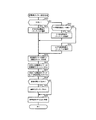
次に、パチンコ機1の遊技進行に応じて主制御基板201で実行される種々の制御処理について図11乃至図18を参照して説明する。図11は、主制御基板201に搭載されるCPU202が実行するメイン処理の一例を示すフローチャートである。図12は、電源断発生時処理の一例を示すフローチャートである。図13は、タイマ割込処理の一例を示すフローチャートである。図14は、主制御基板201で更新される乱数を示す一覧表図である。図15は、遊技処理の一例を示すフローチャートである。図16は、変動開始処理を示すフローチャートである。図17は、大当り判定処理の一例を示すフローチャートである。図18は、変動表示パターン設定処理の一例を示すフローチャートである。図19は、変動表示パターンテーブルの一例を示す一覧表図である。なお、タイマ割込処理は、主制御基板201に搭載されるCPU202により所定のタイミング(本実施形態では、4ms毎)で実行される。   Next, various control processes executed by the main control board 201 in accordance with the game progress of the pachinko machine 1 will be described with reference to FIGS. 11 to 18. FIG. 11 is a flowchart showing an example of main processing executed by the CPU 202 mounted on the main control board 201. FIG. 12 is a flowchart illustrating an example of a process when a power failure occurs. FIG. 13 is a flowchart illustrating an example of timer interrupt processing. FIG. 14 is a list showing random numbers updated on the main control board 201. FIG. 15 is a flowchart showing an example of the game process. FIG. 16 is a flowchart showing the variation start process. FIG. 17 is a flowchart illustrating an example of the big hit determination process. FIG. 18 is a flowchart illustrating an example of the variable display pattern setting process. FIG. 19 is a list showing an example of the variable display pattern table. The timer interrupt process is executed at a predetermined timing (every 4 ms in this embodiment) by the CPU 202 mounted on the main control board 201.

図11に示すように、パチンコ機1へ電力の供給が開始されると、CPU202は、電源投入時処理を実行する(ステップS1)。この電源投入時処理では、RAM204に記憶されているバックアップデータが正常であるか(停電発生時の設定値となっているか)否か判別し、正常であればRAM204に記憶されているバックアップデータに従って停電発生時の状態に戻す処理(復電時処理)を実行し、バックアップデータが異常であればRAM204をクリアしてCPU周辺のデバイス設定(通常の初期設定:割込タイミングの設定等)を行う。なお、遊技途中でパチンコ機1への電力供給が停止すると、RAM204に現在の遊技状態がバックアップデータとして記憶される。また、電源投入時処理にてRAM204に記憶されているバックアップデータのクリアを指示するRAM消去スイッチがオンであれば、RAM204をクリアし、通常の初期設定を行う。また、電源投入時処理にて主制御基板201に搭載されるRAM204にバックアップデータが保存されていない場合には、RAM204をクリアし、通常の初期設定を行う。また、電源投入時処理では、通常の初期設定を実行したときにサブ統合基板211に主制御基板201が起動したことを示す電源投入コマンドを送信可能な状態にセットする処理も実行される。電源投入コマンドは、主制御基板201が起動したことをサブ統合基板211に通知するものである。なお、遊技店の閉店時等にパチンコ機1への電力供給を停止した場合(電源を落とした場合)にもRAM204にバックアップデータが記憶され、再びパチンコ機1への電力供給を開始したときには電源投入時処理が実行される。   As shown in FIG. 11, when the supply of power to the pachinko machine 1 is started, the CPU 202 executes a power-on process (step S1). In this power-on process, it is determined whether or not the backup data stored in the RAM 204 is normal (is a set value when a power failure occurs). If normal, the backup data stored in the RAM 204 is used. Execute processing to restore the power outage (power recovery processing), and if the backup data is abnormal, clear RAM 204 and perform CPU peripheral device settings (normal initial settings: interrupt timing settings, etc.) . When the power supply to the pachinko machine 1 is stopped during the game, the current game state is stored in the RAM 204 as backup data. If the RAM erase switch for instructing the clearing of the backup data stored in the RAM 204 is turned on in the power-on process, the RAM 204 is cleared and normal initialization is performed. If the backup data is not stored in the RAM 204 mounted on the main control board 201 in the power-on process, the RAM 204 is cleared and normal initialization is performed. In the power-on process, a process of setting a power-on command indicating that the main control board 201 is activated to the sub-integrated board 211 when normal initial setting is executed is also executed. The power-on command notifies the sub integrated board 211 that the main control board 201 has been activated. The backup data is also stored in the RAM 204 even when the power supply to the pachinko machine 1 is stopped (when the power is turned off) when the amusement store is closed, etc., and when the power supply to the pachinko machine 1 is started again, the power supply Processing at the time of execution is executed.

電源投入時処理が終了すると、CPU202は、遊技用の各処理を繰り返し実行するループ処理を開始する。このループ処理の開始時には、CPU202は、まず、停電予告信号が検知されているか否かを判定する(ステップS2)。なお、この実施の形態では、パチンコ機1にて使用する電源電圧は、電源基板(図示しない)によって生成する。即ち、パチンコ機1に搭載される複数種類の装置はそれぞれ異なる電源電圧で動作するため、外部電源からパチンコ機1に供給される電源電圧を電源基板にて所定の電源電圧に変換した後、各装置に供給している。しかして、停電が発生し、外部電源から電源基板に供給される電源電圧が所定の電源電圧以下となると、電源基板から主制御基板201に電源電圧の供給が停止することを示す停電予告信号が送信される。そして、ステップS2で主制御基板201に搭載されるCPU202により停電予告信号を検知すると、電源断発生時処理を実行する(ステップS4)。この電源断発生時処理は、停電後に電源基板に供給される電源電圧が(この実施の形態では、24V)復旧した場合に(以下、復電と呼ぶ)、遊技機の動作を停電前の状態から開始するために停電発生時の状態をRAM204にバックアップデータとして記憶する処理である。処理内容は後述するが、本実施例においては、図示する通り、電源断発生時処理は、割込処理ではなく、ループの開始直後に停電予告信号の検知有無に応じて実行される分岐処理としてメイン処理(主制御処理)内に組み込まれている。   When the power-on process ends, the CPU 202 starts a loop process that repeatedly executes each process for gaming. At the start of this loop process, the CPU 202 first determines whether or not a power failure notice signal has been detected (step S2). In this embodiment, the power supply voltage used in the pachinko machine 1 is generated by a power supply board (not shown). That is, since a plurality of types of devices mounted on the pachinko machine 1 operate with different power supply voltages, the power supply voltage supplied from the external power supply to the pachinko machine 1 is converted into a predetermined power supply voltage on the power supply board, Supplying to the device. Thus, when a power failure occurs and the power supply voltage supplied from the external power supply to the power supply board is equal to or lower than the predetermined power supply voltage, a power failure warning signal indicating that the supply of power supply voltage from the power supply board to the main control board 201 is stopped is generated. Sent. Then, when a power failure notice signal is detected by the CPU 202 mounted on the main control board 201 in step S2, a process at the time of occurrence of power interruption is executed (step S4). When the power interruption occurs, the operation of the gaming machine is in a state before the power failure when the power supply voltage supplied to the power supply board after the power failure is restored (24V in this embodiment) (hereinafter referred to as power recovery). This is a process of storing the state at the time of the occurrence of a power failure as backup data in the RAM 204 in order to start from the above. Although the processing content will be described later, in the present embodiment, as shown in the figure, the processing at the time of power failure occurrence is not an interrupt processing, but as a branch processing that is executed immediately after the start of the loop depending on whether or not a power failure warning signal is detected. It is incorporated in the main process (main control process).

ステップS2で停電予告信号が検知されていない場合、即ち外部電源からの電力が正常に供給されている場合には、遊技にて用いられる各種乱数を更新する乱数更新処理2を行う(ステップS3)。なお、乱数更新処理2にて更新される乱数については後述する。   When the power failure warning signal is not detected in step S2, that is, when the power from the external power supply is normally supplied, random number update processing 2 for updating various random numbers used in the game is performed (step S3). . The random number updated in the random number update process 2 will be described later.

図12は、電源断発生時処理(ステップS4)の一例を示すフローチャートである。上述したように、電源断発生時処理は、メイン処理において、停電予告信号が検出された時に実行される処理である。CPU202は、まず、割込処理が実行されないように割込禁止設定を行う(ステップS4a)。そして、RAM204のチェックサムを算出し、RAM204の所定領域に保存する(ステップS4b)。このチェックサムは、復電時に停電前のRAM204の内容が保持されているか否かをチェックするのに使用される。   FIG. 12 is a flowchart showing an example of the process at the time of power-off occurrence (step S4). As described above, the power failure occurrence process is a process executed when a power failure warning signal is detected in the main process. First, the CPU 202 performs an interrupt prohibition setting so that the interrupt process is not executed (step S4a). Then, the checksum of the RAM 204 is calculated and stored in a predetermined area of the RAM 204 (step S4b). This checksum is used to check whether or not the content of the RAM 204 before the power failure is retained at the time of power recovery.

次いで、CPU202は、RAM204の所定領域に設けられたバックアップフラグに、電源断発生時処理が行われたことを示す規定値を設定する(ステップS4c)。以上の処理を終えると、CPU202は、RAM204へのアクセスを禁止し(ステップS4d)、無限ループに入って電力供給の停止に備える。なお、この処理では、ごく短時間の停電等(以下、「瞬停」と呼ぶ)によって、電源電圧が不安定となることによって、電源断発生時処理が開始されてしまった場合、実際には電源電圧は停止されないため、上記処理では、無限ループから復帰することができなくなるおそれがある。かかる弊害を回避するため、本実施例のCPU202には、ウォッチドックタイマが設けられており、所定時間、ウォッチドックタイマが更新されないとリセットがかかるように構成されている。ウォッチドックタイマは、正常に処理が行われている間は定期的に更新されるが、電源断発生時処理に入り、更新が行われなくなる。この結果、瞬停によって、電源断発生時処理に入り、図12の無限ループに入った場合でも、所定期間経過後にリセットがかかり、電源投入時と同じプロセスでCPU202が起動することになる。   Next, the CPU 202 sets a specified value indicating that the process at the time of power-off occurrence has been performed in a backup flag provided in a predetermined area of the RAM 204 (step S4c). When the above processing is completed, the CPU 202 prohibits access to the RAM 204 (step S4d) and enters an infinite loop to prepare for stopping power supply. In this process, if the power supply voltage becomes unstable due to a very short power failure, etc. (hereinafter referred to as “instantaneous power interruption”), the process at the time of the occurrence of power interruption has started. Since the power supply voltage is not stopped, there is a possibility that the process described above cannot return from the infinite loop. In order to avoid such an adverse effect, the CPU 202 of this embodiment is provided with a watchdog timer, and is configured to be reset if the watchdog timer is not updated for a predetermined time. The watchdog timer is periodically updated while the process is normally performed. However, the watchdog timer enters the process when the power is cut off and is not updated. As a result, even when the power interruption occurs due to an instantaneous power failure and the infinite loop shown in FIG. 12 is entered, a reset is applied after a predetermined period of time, and the CPU 202 is activated in the same process as when the power is turned on.

図13は、タイマ割込処理の一例を示すフローチャートである。上述したように、この実施の形態では、メイン処理の実行中に主制御基板201に搭載されるCPU202により4ms毎にタイマ割込処理が実行される。タイマ割込処理において、CPU202は、レジスタの退避処理を実行した後(ステップS10)、ステップS11からステップS19の処理を実行する。ステップS11のスイッチ入力処理では、上述したスイッチ(ゲートスイッチ74a、始動口スイッチ68a,70b、カウントスイッチ72a、普通入賞スイッチ76a等)の検出信号を監視する処理を実行する。ステップS12の払出動作処理では、スイッチ入力処理(ステップS11)にて検出された信号に基づいて払出基板205に遊技球の払い出しを指示する払出コマンドを送信する。ステップS13の乱数更新処理1では、遊技にて用いられる各種乱数を更新する処理を実行する。なお、この実施の形態では、乱数更新処理1にて更新される乱数と、上述した乱数更新処理2にて更新される乱数と、は異なる。乱数については後述するが、乱数更新処理2にて更新される乱数を乱数更新処理1でも更新するようにしてもよい。   FIG. 13 is a flowchart illustrating an example of timer interrupt processing. As described above, in this embodiment, the timer interrupt process is executed every 4 ms by the CPU 202 mounted on the main control board 201 during the execution of the main process. In the timer interrupt process, the CPU 202 executes the process from step S11 to step S19 after executing the register saving process (step S10). In the switch input process of step S11, a process of monitoring the detection signals of the above-described switches (gate switch 74a, start port switches 68a and 70b, count switch 72a, normal winning switch 76a, etc.) is executed. In the payout operation process in step S12, a payout command for instructing payout of the game ball is transmitted to the payout board 205 based on the signal detected in the switch input process (step S11). In the random number update process 1 in step S13, a process of updating various random numbers used in the game is executed. In this embodiment, the random number updated in the random number update process 1 is different from the random number updated in the random number update process 2 described above. Although the random number will be described later, the random number updated in the random number update process 2 may be updated in the random number update process 1 as well.

また、ステップS14の遊技処理では、遊技の進行状態に応じてパチンコ機1を制御する処理が実行される。ステップS15の普通図柄遊技では、普通図柄表示LED146aに関わる制御処理を実行する。ステップS16の普通電動役物遊技では、開閉部材56aの開閉制御するための処理を実行する。ステップS17の特別図柄遊技では、遊技処理(ステップS14)の処理の結果に基づいて特別図柄表示LED144aを変動表示する制御を実行する。ステップS18の特別電動役物遊技では、ソレノイド73aを可動制御して開閉部材72aの開閉制御を実行する。ステップS19のコマンド伝送出力処理では、遊技処理(ステップS14)でセットされた演出コマンドをサブ統合基板211に送信する処理を実行する。また、コマンド伝送出力処理(ステップS19)では、パチンコ機1への電力供給が開始されたときに電源投入時処理(ステップS1)でセットされた電源投入コマンドをサブ統合基板211に送信する処理も行われる。ステップS20のI/Oポート出力処理では、パチンコ機1の外部(例えば、管理コンピュータ等)に遊技状態を示す状態信号を出力する処理、特図始動記憶ランプ147に駆動信号を出力する処理、等を実行する。ステップS11からステップS20の処理を実行すると、レジスタの復帰処理(ステップS21)を実行して、処理を終了する。   Moreover, in the game process of step S14, the process which controls the pachinko machine 1 according to the progress state of a game is performed. In the normal symbol game of step S15, the control process related to the normal symbol display LED 146a is executed. In the ordinary electric accessory game in step S16, processing for opening / closing control of the opening / closing member 56a is executed. In the special symbol game in step S17, control is performed to display the special symbol display LED 144a in a variable manner based on the result of the game process (step S14). In the special electric accessory game of step S18, the solenoid 73a is controlled to move and the opening / closing control of the opening / closing member 72a is executed. In the command transmission output process of step S19, a process of transmitting the effect command set in the game process (step S14) to the sub integrated board 211 is executed. In the command transmission output process (step S19), a process of transmitting the power-on command set in the power-on process (step S1) to the sub-integrated board 211 when power supply to the pachinko machine 1 is started. Done. In the I / O port output process of step S20, a process of outputting a state signal indicating a gaming state to the outside of the pachinko machine 1 (for example, a management computer), a process of outputting a drive signal to the special figure start memory lamp 147, etc. Execute. When the processing from step S11 to step S20 is executed, the register restoration processing (step S21) is executed, and the processing is terminated.

ここで、上述した乱数更新処理1(ステップS13)及び乱数更新処理2(ステップS3)で主制御基板201に搭載されるCPU202により更新される各種乱数について図14を参照して説明する。図14に示すように、この実施の形態では、遊技にて用いられる各種乱数として、大当り遊技状態を発生させるか否かの判定(大当り判定)に用いられる大当り判定乱数、大当り判定において大当り遊技状態を発生させると判定されたときに確変大当りとするか否かの判定(確変判定)に用いられる確変判定乱数、大当り判定にて大当り遊技状態を発生させないと判定されたときにリーチ態様を伴うはずれとするか否かの判定(リーチ判定)に用いられるリーチ判定乱数、特別図柄表示LED144aに表示されている特別図柄の変動表示パターンを決定するために用いられる変動表示パターン乱数、入球装置56の開閉部材56aを開放状態に制御するか否かの判定(普通図柄当り判定)に用いられる普通図柄当り判定乱数、等がある。なお、リーチ判定用乱数を用いて特別図柄の変動表示パターンを決定すると共に、液晶表示器50にて表示制御される装飾図柄の変動表示パターンを決定するようにしてもよい。   Here, various random numbers updated by the CPU 202 mounted on the main control board 201 in the random number update process 1 (step S13) and the random number update process 2 (step S3) described above will be described with reference to FIG. As shown in FIG. 14, in this embodiment, as the various random numbers used in the game, the big hit determination random number used for determining whether or not to generate the big hit gaming state (big hit determination), the big hit gaming state in the big hit determination Is a probability variation determination random number used to determine whether or not to be a probability variation big hit (probability variation determination) when it is determined that a big hit gaming state will not be generated in the big hit determination, and it is out of reach with a reach mode Reach determination random number used for determination (reach determination), variation display pattern random number used to determine the variation display pattern of the special symbol displayed on the special symbol display LED 144a, There is a normal symbol determination random number used for determining whether or not the opening / closing member 56a is controlled to be in an open state (normal symbol determination). Note that the variable display pattern of the special symbol may be determined using the reach determination random number, and the variable display pattern of the decorative symbol controlled by the liquid crystal display 50 may be determined.

これらの乱数のうち、乱数更新処理1では、大当り遊技状態の発生に関わる大当り判定乱数、確変判定乱数、及び入球装置56の開閉部材56aを開放状態に制御するか否かに関わる普通図柄当り判定乱数の更新を行う。即ち、大当り遊技状態の発生及び条件作動装置の開閉部材72aを開放状態に制御するか否かに関わる判定に用いられる乱数は所定のタイミングとして4ms毎に更新される。このようにすることにより、それぞれの乱数における所定期間における確率(大当り遊技状態を発生させると判定する確率、条件作動装置の開閉部材72aを開放状態に制御すると判定する確率)を一定にすることができ、遊技者不利な状態となることを防止できる。一方、乱数更新処理2では、大当り遊技状態の発生及び普通図柄の表示結果に関わらないリーチ判定乱数及び変動表示パターン乱数の更新を行う。なお、主制御基板201で更新される乱数は、上記したものに限られず、乱数更新処理2では、大当り判定乱数を更新するカウンタが1周したときに次にカウントを開始させる大当り判定乱数の初期値を決定するための初期値決定乱数等の更新も行う。   Among these random numbers, in the random number update processing 1, per jackpot determination random number related to occurrence of the jackpot gaming state, probability variation determination random number, and normal symbol pertinent to determine whether or not the opening / closing member 56a of the pitching device 56 is controlled to the open state Update the decision random number. That is, the random number used for the determination regarding whether or not the big hit gaming state is generated and whether or not the open / close member 72a of the conditional operation device is controlled to the open state is updated every 4 ms as a predetermined timing. By doing in this way, the probability (probability to determine that the big hit gaming state is generated, probability to determine to control the open / close member 72a of the conditional operation device to be in the open state) in each random number in a predetermined period can be made constant. It is possible to prevent the player from being disadvantaged. On the other hand, in the random number update process 2, the reach determination random number and the variable display pattern random number are updated regardless of the occurrence of the big hit gaming state and the display result of the normal symbol. Note that the random numbers updated by the main control board 201 are not limited to those described above. In the random number update processing 2, the initial of the big hit determination random number that starts counting next when the counter that updates the big hit determination random number makes one round. The initial value determination random number for determining the value is also updated.

図15は、遊技処理(ステップS14)の一例を示すフローチャートである。遊技制御処理において、CPU202は、まず、上始動口68及び下始動口70に遊技球が入賞したか否かを判別する(ステップS30)。具体的には、始動口スイッチ68a,70bから検出信号が出力されたか否かを判別し、始動口スイッチ68a,70bから検出信号が出力された場合には上始動口68及び下始動口70に遊技球が入賞した(ステップS30にてYES)と判別し、始動口スイッチ68a,70bからの検出信号が出力されていなければ上始動口68及び下始動口70に遊技球が入賞していない(ステップS30にてNO)と判別する。ステップS30にて上始動口68及び下始動口70に遊技球が入賞したと判別したときには、各種乱数(大当り判定乱数、確変判定乱数、等)を取得し、RAM204に設けられている保留球数カウンタの値が上限値となる4未満であるか否かを判別する(ステップS31)。そして、ステップS31で保留球数カウンタが4未満であれば、始動記憶格納処理を行う(ステップS32)。なお、ステップS30で始動口スイッチ68a,70bがオンしていない場合、及びステップS31で保留球数カウンタの値が4である場合、には、始動記憶格納処理を実行しない。その後、CPU202は、遊技の進行状態を示す処理選択フラグの値を参照してステップS40〜ステップS44のうちいずれかの処理を行う。   FIG. 15 is a flowchart showing an example of the game process (step S14). In the game control process, the CPU 202 first determines whether or not a game ball has won the upper start opening 68 and the lower start opening 70 (step S30). Specifically, it is determined whether or not a detection signal is output from the start port switches 68a and 70b, and when a detection signal is output from the start port switches 68a and 70b, the upper start port 68 and the lower start port 70 are output. If it is determined that the game ball has won (YES in step S30) and no detection signal is output from the start port switches 68a and 70b, no game ball has been won in the upper start port 68 and the lower start port 70 ( In step S30, NO is determined. When it is determined in step S30 that a game ball has won the upper start port 68 and the lower start port 70, various random numbers (big hit determination random number, probability variation determination random number, etc.) are acquired, and the number of reserved balls provided in the RAM 204 It is determined whether or not the counter value is less than 4 which is the upper limit value (step S31). Then, if the held ball number counter is less than 4 in step S31, start memory storage processing is performed (step S32). If the start port switches 68a and 70b are not turned on in step S30, and if the value of the reserved ball number counter is 4 in step S31, the start storage storing process is not executed. Thereafter, the CPU 202 refers to the value of the process selection flag indicating the progress of the game, and performs any one of steps S40 to S44.

始動記憶格納処理では、保留球数カウンタに「1」を加算する処理と、保留球数カウンタの加算に伴って特図始動記憶LED144bの点灯表示態様(点灯表示させるLEDの個数)を変更する処理と、取得した乱数値(この実施の形態では、大当り判定乱数、確変判定乱数)をRAM204に設けられた始動記憶の保存領域に保留球数カウンタのカウント値に対応させて記憶する処理と、を行う。このように、保留球数カウンタは、始動記憶の保存領域に記憶される乱数値の数を示すカウンタである。また、ステップS31において保留球数カウンタの値が上限値である場合にはステップS30で取得した乱数値を破棄する。なお、ステップS30で上始動口68又は下始動口70に遊技球が入賞したと判別したときには、ステップS30〜ステップS32の間で各種乱数を取得すればよく、例えば、ステップS30で各種乱数を取得せずに、ステップS31で保留球数カウンタが上限値未満であることを判別した後に、各種乱数を取得してもよいし、始動記憶格納処理(ステップS32)で取得するようにしてもよい。   In the start memory storing process, a process of adding “1” to the held ball number counter and a process of changing the lighting display mode (number of LEDs to be turned on) of the special figure start memory LED 144b in accordance with the addition of the held ball number counter. And a process of storing the acquired random number value (in this embodiment, the big hit determination random number, the probability variation determination random number) in the storage area of the start memory provided in the RAM 204 in correspondence with the count value of the reserved ball number counter. Do. Thus, the reserved ball number counter is a counter indicating the number of random numbers stored in the storage area of the start memory. If the value of the reserved ball number counter is the upper limit value in step S31, the random number value acquired in step S30 is discarded. If it is determined in step S30 that a game ball has won the upper start opening 68 or the lower start opening 70, various random numbers may be acquired between step S30 and step S32. For example, various random numbers are acquired in step S30. Instead, after it is determined in step S31 that the reserved ball number counter is less than the upper limit value, various random numbers may be acquired, or may be acquired in the start storage storage process (step S32).

処理選択フラグが「0」のときに実行される変動開始処理(ステップS40)では、始動記憶数を確認し、始動記憶数が0でなければ、特別図柄の変動表示を開始するための設定を行う。詳しくは後述するが具体的には、大当り遊技状態を発生させるか否かの判定を行い、大当り遊技状態を発生させる場合には、確変大当りとするか否かを判定する。処理選択フラグが「1」のときに実行される変動表示パターン設定処理(ステップS41)では、特別図柄及び装飾図柄の変動表示に関わる設定を行う。詳しくは後述するが具体的には、特別図柄の変動表示パターンを決定し、当該変動表示パターンに対応して設定される変動時間(特別図柄表示LED144aにて特別図柄の変動表示を開始してから停止表示するまでの時間)をタイマにセットする。処理選択フラグが「2」のときに実行される変動中処理(ステップS42)では、変動表示パターン設定処理(ステップS41)で変動時間が設定されたタイマを監視し、タイマがタイムアウトしたことに基づいて特別図柄表示LED144aにおける特別図柄の変動表示を停止させる処理を行う。このとき、変動開始処理(ステップS40)にて大当り遊技状態とする判定がなされていれば、処理選択フラグを「3」に更新し、大当り遊技状態とする判定がなされていなければ処理選択フラグを「0」に更新する。   In the variation start process (step S40) executed when the process selection flag is “0”, the start memory number is confirmed. If the start memory number is not 0, a setting for starting the variation display of the special symbol is made. Do. As will be described in detail later, specifically, it is determined whether or not a big hit gaming state is to be generated. In the variable display pattern setting process (step S41) executed when the process selection flag is “1”, settings related to the variable display of special symbols and decorative symbols are performed. Specifically, although the details will be described later, the variation display pattern of the special symbol is determined, and the variation time set corresponding to the variation display pattern (after the variation display of the special symbol is started by the special symbol display LED 144a) Set the timer until the stop display. In the changing process (step S42) executed when the process selection flag is “2”, the timer set with the changing time in the changing display pattern setting process (step S41) is monitored, and the timer has timed out. Then, the special symbol display LED 144a performs a process of stopping the variation display of the special symbol. At this time, if it is determined in the variation start process (step S40) that the big hit gaming state has been made, the process selection flag is updated to “3”, and if it is not judged that the big hit gaming state has been made, the processing selection flag is set. Update to “0”.

また、処理選択フラグが「3」のときに実行される大当り遊技開始処理(ステップS43:利益付与状態制御手段)では、大当り遊技状態を開始するための設定を行う。具体的には、サブ統合基板211に大当り遊技状態の開始表示の実行を指示する大当り開始コマンドを送信すると共に、条件作動装置の開放回数等の設定を行う。   Further, in the big hit game start process (step S43: profit grant state control means) executed when the process selection flag is “3”, a setting for starting the big hit game state is performed. Specifically, a jackpot start command for instructing execution of the start display of the jackpot gaming state is transmitted to the sub-integrated board 211, and the number of times of opening of the conditional operation device is set.

処理選択フラグが「4」のときに実行される大当り遊技中処理(ステップS44:利益付与状態制御手段)では、大当り遊技状態が開始された場合に、カウントスイッチ72aによって検出された遊技球の個数を判別し、所定個数(この実施の形態では、9個)の遊技球が大入賞口62に入賞したとき、又は、所定期間(この実施の形態では、30秒)が経過したとき条件作動装置を閉塞状態にするための処理を行う(実行期間制限手段)と共に、サブ統合基板211に大当り遊技状態中の表示(例えば、ラウンド表示等)の実行を指示する大当り中コマンドを送信する。また、大当り遊技状態におけるラウンド回数が所定回数(この実施の形態では、15回)に達していなければ、再び、条件作動装置を開放状態にするための処理を行い、大当り遊技状態におけるラウンド回数が所定回数に達したときには、サブ統合基板211に大当り遊技状態の終了表示の実行を指示する大当り終了コマンドを送信すると共に処理選択フラグを「0」に更新する。   In the big hit game processing executed when the process selection flag is “4” (step S44: profit grant state control means), the number of game balls detected by the count switch 72a when the big hit game state is started. When a predetermined number (9 in this embodiment) of game balls wins the big prize opening 62 or when a predetermined period (30 seconds in this embodiment) elapses, the condition actuating device In addition to performing a process for putting the game in a closed state (execution period limiting means), a sub-hit command for instructing the sub-integrated board 211 to execute a display (for example, round display) during the big hit gaming state is transmitted. Also, if the number of rounds in the big hit gaming state has not reached the predetermined number (15 in this embodiment), the processing for opening the conditional operation device is performed again, and the number of rounds in the big hit gaming state is When the predetermined number of times is reached, a jackpot end command for instructing execution of a jackpot gaming state end display is transmitted to the sub-integrated board 211 and the processing selection flag is updated to “0”.

図16は、変動開始処理(ステップS40)の一例を示すフローチャートである。変動開始処理において、CPU202は、保留球数カウンタの値が0であるか否か判別する(ステップS401)。上述したように、保留球数カウンタの値は、始動記憶の保存領域に格納される乱数値の数を示すものであるため、ステップS401で保留球数カウンタの値が0であれば、始動記憶がないと判別されて処理を終了する。   FIG. 16 is a flowchart illustrating an example of the variation start process (step S40). In the change start process, the CPU 202 determines whether or not the value of the reserved ball number counter is 0 (step S401). As described above, since the value of the held ball number counter indicates the number of random numbers stored in the start memory storage area, if the value of the held ball number counter is 0 in step S401, the start memory is stored. It is determined that there is no data, and the process is terminated.

一方、ステップS401で保留球数カウンタの値が0でなければ、始動記憶移行処理を実行する(ステップS402)。始動記憶移行処理では、保留球数カウンタを1減算する処理と、RAM204に設けられた始動記憶の保存領域に記憶される各種乱数をシフトした後、始動記憶の保存領域のうち保留球数カウンタの0に対応する保存領域に保存される各種乱数(大当り判定乱数等)を読み出す処理と、を行う。具体的には、始動記憶の保存領域にて保留球数カウンタのn(n=1、2、3、4)に対応する保存領域に記憶されている各種乱数を始動記憶の保存領域における保留球数カウンタのn−1(n=0、1、2、3)に対応する保存領域に記憶させる。   On the other hand, if the value of the reserved ball number counter is not 0 in step S401, a start memory transfer process is executed (step S402). In the start memory transfer process, the process of subtracting 1 from the reserved ball number counter, and after shifting various random numbers stored in the start memory storage area provided in the RAM 204, the stored ball counter of the start memory storage area A process of reading various random numbers (such as jackpot determination random numbers) stored in the storage area corresponding to 0 is performed. Specifically, various random numbers stored in the storage area corresponding to n (n = 1, 2, 3, 4) of the reserved ball number counter in the storage area of the start memory are stored in the storage area of the start memory. The number is stored in a storage area corresponding to n-1 (n = 0, 1, 2, 3) of the number counter.

次いで、ステップS402で保留記憶の保存領域のうち保留球数カウンタの0に対応する保存領域から読み出した大当り判定乱数を用いて大当り遊技状態を発生させるか否かの判定を行い、大当り遊技状態を発生させる場合には、確変大当りとするか否かを判定する大当り判定処理を行った後(ステップS403)、処理選択フラグを「1」に更新する(ステップS404)。処理選択フラグを「1」に更新することにより、次にタイマ割込処理が発生し、遊技処理(ステップS14)が実行されたときに変動表示パターン設定処理(ステップS41)が実行可能となる。   Next, in step S402, it is determined whether or not to generate a big hit gaming state using the big hit determination random number read from the storage area corresponding to 0 of the reserved ball number counter among the storage areas of the reserved memory, and the big hit gaming state is determined. In the case of generating, after the big hit determination process for determining whether or not the probability variation big hit is made (step S403), the process selection flag is updated to “1” (step S404). By updating the process selection flag to “1”, the timer interrupt process occurs next, and the variable display pattern setting process (step S41) can be executed when the game process (step S14) is executed.

図17は、大当り判定処理(ステップS404)の一例を示すフローチャートである。大当り判定処理において、CPU202は、大当り遊技中処理(ステップS44)でセットされる確変フラグがON状態であるか(セットされているか)否かを判別する(ステップS51)。確変フラグがON状態であれば、確変状態時大当り判定テーブル(図示しない)を選択し(ステップS52:高確率状態制御手段)、確変状態フラグがON状態でなければ(OFF状態であれば)、通常・時短状態時大当り判定テーブル(図示しない)を選択する(ステップS53:通常状態制御手段)。なお、確変状態時大当り判定テーブルでは、0〜979までの980個の大当り判定乱数のうち大当り判定乱数と一致することにより大当り遊技状態を発生させることが決定される大当り判定値が14個設定され、大当りとなる確率である大当り確率が1/70となっている。一方、通常・時短状態時大当り判定テーブルでは、0〜979までの980個の大当り判定乱数のうち大当り判定値が2個設定され、大当り確率が1/490となっている。   FIG. 17 is a flowchart illustrating an example of the big hit determination process (step S404). In the big hit determination process, the CPU 202 determines whether or not the probability variation flag set in the big hit game process (step S44) is ON (set) (step S51). If the probability variation flag is ON, a probability variation state big hit determination table (not shown) is selected (step S52: high probability state control means), and if the probability variation state flag is not ON (if it is OFF), A big hit determination table (not shown) in the normal / short time state is selected (step S53: normal state control means). In the promiscuous state jackpot determination table, 14 jackpot determination values that are determined to generate a jackpot gaming state by matching the jackpot determination random number among 980 jackpot determination random numbers from 0 to 979 are set. The jackpot probability, which is the probability of a jackpot, is 1/70. On the other hand, in the normal / short time state big hit determination table, two big hit determination values are set out of 980 big hit determination random numbers from 0 to 979, and the big hit probability is 1/490.

そして、ステップS52,S53で選択した確変状態時大当り判定テーブル、又は、通常・時短状態時大当り判定テーブルに設定されている判定値と、ステップS402の始動記憶移行処理で読み出した大当り判定乱数の値と、が一致するか否かによって、大当り遊技状態を発生させるか否か判定する(ステップS54)。ステップS52,S53で選択した確変状態時大当り判定テーブル、又は、通常・時短状態時大当り判定テーブルに設定されている判定値と、ステップS402の始動記憶移行処理で読み出した大当り判定乱数の値(保留球数カウンタの0に対応する保存領域に保存される大当り判定乱数の値)と、が一致することに基づいて大当り遊技状態を発生させると判定したときには、大当りフラグをON状態(セット)とした後に(ステップS55)、所定の判定値が設定された確変判定テーブル(図示しない)に基づいて確変大当りとするか否かを判定する(ステップS56:高確率状態判定手段)。具体的には、ステップS402の始動記憶移行処理で読み出した確変判定乱数の値(保留球数カウンタの0に対応する保存領域に保存される確変判定乱数の値)と、確変判定テーブルに設定されている判定値と、が一致するか否かに基づいて確変大当りとするか否か判定する。なお、本実施形態では、確変突入率(大当りのうち確変大当りとする割合)が2/3となるように、即ち、0〜8までの9個の確変判定乱数のうち確変大当りとすることに決定される6個の判定値が確変判定テーブルに設定されている。   Then, the determination value set in the probability change state big hit determination table selected in steps S52 and S53, or the normal / short-time state big hit determination table, and the value of the big hit determination random number read out in the start memory transfer process in step S402 And whether or not to generate a big hit gaming state is determined (step S54). The determination value set in the probability change state big hit determination table selected in steps S52 and S53, or the normal / short-time state big hit determination table, and the value of the big hit determination random number read in the start memory transfer process in step S402 (hold) The jackpot flag is set to ON when it is determined that a jackpot gaming state is to be generated based on a match with the value of the jackpot determination random number stored in the storage area corresponding to 0 of the ball counter. Later (step S55), it is determined based on a probability variation determination table (not shown) in which a predetermined criterion value is set whether or not the probability variation big hit is made (step S56: high probability state determination means). Specifically, it is set in the probability variation determination table and the value of the probability variation determination random number read in the start memory transition process in step S402 (value of the probability variation determination random number stored in the storage area corresponding to 0 of the reserved ball number counter). It is determined whether or not to be a probable big hit based on whether or not the determination value matches. In the present embodiment, the probability variation entry rate (the ratio of the probability variation to the probability variation big hit) is 2/3, that is, the probability variation big hit among the nine probability variation determination random numbers from 0 to 8. Six determination values to be determined are set in the probability variation determination table.

ステップS56で、確変判定テーブルに設定されている判定値と、ステップS402の始動記憶移行処理で読み出した確変判定乱数の値と、が一致したことに基づいて確変大当りと判定されたときには、確変状態フラグをON状態(セット)とする(ステップS57)。一方、ステップS54で大当りとしない(はずれとする)と判定されたとき、及び、ステップS56で確変大当りとしない(非確変大当りとする)と判定されたとき、には、以下の処理を実行することなく処理を終了する。なお、大当りフラグ及び確変状態フラグのON/OFF状態(セット状態、リセット状態)は、RAM204に記憶される。また、大当りフラグ及び確変状態フラグのOFF状態(リセット状態)とは「0」の値がセットされることであり、大当りフラグ及び確変状態フラグのON状態(セット状態)とは「1」の値がセットされることである。   If it is determined in step S56 that the determination value set in the probability variation determination table and the value of the probability variation determination random number read in the start memory transfer process in step S402 match, the probability variation state is determined. The flag is turned on (set) (step S57). On the other hand, when it is determined in step S54 that a big hit is not made (deviated) and in step S56, it is decided that a probability variation big hit is not made (non-probable variation big hit), the following processing is executed. The process ends without Note that the ON / OFF states (set state, reset state) of the big hit flag and the probability variation state flag are stored in the RAM 204. The OFF state (reset state) of the big hit flag and the probability change state flag is a value of “0”, and the ON state (set state) of the big hit flag and the probability change state flag is a value of “1”. Is set.

なお、大当りフラグは、大当り遊技状態への移行制御を示すフラグであり、大当り遊技開始処理(ステップS43)にて大当りフラグがセットされていれば、大当り遊技状態を発生させる。また、確変状態フラグは、大当り遊技状態終了後に確率変動状態への移行制御を示すフラグであり、大当り遊技中処理(ステップS44)にて大当り遊技状態を終了するときに確変状態フラグがセットされていれば、確変状態フラグをリセットし、確変状態を示す確変フラグをセットする処理が実行される。確変フラグがセットされた状態では、上述した確率変動状態に制御され、例えば、上述したステップS52の確変状態時大当り判定テーブルが選択されて確率変動状態以外の状態(通常状態、時短状態)よりも大当り遊技状態を発生させると判定される確率が高まる。また、大当り遊技開始処理(ステップS43)にて確変フラグがセットされている場合には、確変フラグをリセットする処理が実行される。   Note that the big hit flag is a flag indicating control for shifting to the big hit gaming state. If the big hit flag is set in the big hit game start process (step S43), the big hit gaming state is generated. The probability change state flag is a flag indicating the transition control to the probability variation state after the big hit gaming state is finished, and the probability change state flag is set when the big hit gaming state is ended in the big hit gaming process (step S44). Then, the process of resetting the probability variation state flag and setting the probability variation flag indicating the probability variation state is executed. In the state in which the probability variation flag is set, the probability variation state is controlled as described above. For example, the probability variation state big hit determination table in step S52 described above is selected and the state other than the probability variation state (normal state, time reduction state). The probability of determining that a big hit gaming state is to be generated is increased. If the probability variation flag is set in the big hit game start processing (step S43), processing for resetting the probability variation flag is executed.

図18は、変動表示パターン設定処理(ステップS41:演出形態選択手段)の一例を示すフローチャートである。変動表示パターン設定処理において、CPU202は、今回の変動表示の結果、大当りとするか否か、即ち、大当りフラグがセットされているか否かを判別し(ステップS410)、大当りフラグがセットされていれば(ON状態であれば)、大当りとなる場合に用いられる変動表示パターンが設定された大当り時変動表示パターンテーブル(図19参照)を選択する(ステップS412)。また、大当りフラグがセットされていなければ(OFF状態であれば)、リーチ判定乱数を取得し、RAM204の所定の保存領域に記憶すると共に、所定の判定値が設定されたリーチ判定テーブルに設定されている判定値と、取得したリーチ判定乱数の値と、が一致するか否かによって、リーチとするか否かを判定する(ステップS411)。リーチ態様とすると判定されたときには、リーチ態様を伴うはずれ図柄を導出する態様が示された変動表示パターンが設定されたリーチ時変動表示パターンテーブル(図19参照)を選択し(ステップS413)、リーチ態様としないと判定されたときには、リーチ態様を伴わないはずれ図柄を導出する態様が示された変動表示パターンが設定されたはずれ時変動表示パターンテーブル(図19参照)を選択する(ステップS414)。なお、リーチ判定テーブルでは、リーチ確率(リーチ態様とする割合)が1/12.5となるように、即ち、0〜24までの25個のリーチ判定乱数のうち2個の判定値がリーチ判定テーブルに設定されている。   FIG. 18 is a flowchart showing an example of the variable display pattern setting process (step S41: effect form selecting means). In the variable display pattern setting process, the CPU 202 determines whether or not a big hit is made as a result of the current variable display, that is, whether or not the big hit flag is set (step S410), and the big hit flag is set. If it is ON (if it is in the ON state), the big hit time fluctuation display pattern table (see FIG. 19) in which the fluctuation display pattern used when the big hit is set is selected (step S412). If the big hit flag is not set (if it is OFF), a reach determination random number is acquired and stored in a predetermined storage area of the RAM 204 and set in a reach determination table in which a predetermined determination value is set. It is determined whether or not the reach is determined based on whether or not the determined determination value matches the value of the acquired reach determination random number (step S411). When it is determined that the reach mode is selected, a reach-time variation display pattern table (see FIG. 19) in which a variation display pattern showing a mode for deriving an outlier symbol with a reach mode is set is selected (step S413), and reach is performed. When it is determined not to be an aspect, the detachment fluctuation display pattern table (see FIG. 19) in which a fluctuation display pattern showing an aspect for deriving a losing symbol without a reach aspect is set is selected (step S414). In the reach determination table, the reach probability (reach mode ratio) is 1 / 12.5, that is, two determination values out of 25 reach determination random numbers from 0 to 24 are reach determination. Set in the table.

そして、変動表示パターン乱数を取得し、RAM204の所定の保存領域に記憶すると共に、ステップS411,S413,S414で選択された大当り時変動表示パターンテーブル、リーチ時変動表示パターンテーブル、はずれ時変動表示パターンテーブル、のいずれか1つの変動表示パターンテーブルに設定されている判定値と、取得した変動表示パターン乱数の値と、が一致する変動表示パターンに決定する(ステップS415)。   Then, the variable display pattern random number is acquired and stored in a predetermined storage area of the RAM 204, and the big hit variable display pattern table, the reach variable display pattern table selected in Steps S411, S413, and S414, the shift variable display pattern The variation display pattern in which the determination value set in any one variation display pattern table of the table matches the value of the acquired variation display pattern random number is determined (step S415).

なお、はずれ時変動表示パターンテーブルは、後述する変動番号1の「通常変動」の変動表示パターンのみ設定されるテーブルと、変動番号2の「短縮変動」の変動表示パターンのみ設定されるテーブルと、を有し、上述した時短制御が実行されていない場合には、変動番号1の「通常変動」の変動表示パターンのみ設定されるテーブルが選択され、時短制御が実行されている場合には、変動番号2の「短縮変動」の変動表示パターンのみ設定されるテーブルが選択される。即ち、時短制御が実行されていない場合には、変動番号1の「通常変動」の変動表示パターンに決定され、時短制御が実行されている場合には、変動番号2の「短縮変動」の変動表示パターンに決定される。また、変動番号2の「短縮変動」の変動表示パターン(テーブル)は、時短制御が実行されていない場合であっても、始動口スイッチ68a,170aにより検出されたことに基づいて抽出された大当り判定乱数の記憶数を示す保留球数カウンタの値が上限値、確率変動状態、等の条件のうちいずれかが成立したときに選択され得る。   The deviation fluctuation display pattern table includes a table in which only a fluctuation display pattern of “normal fluctuation” of fluctuation number 1 described later is set, a table in which only a fluctuation display pattern of “shortening fluctuation” in fluctuation number 2 is set, When the above-mentioned time-shortening control is not executed, a table in which only the fluctuation display pattern of “normal fluctuation” with the fluctuation number 1 is set is selected. A table in which only the variation display pattern of “shortening variation” of No. 2 is set is selected. That is, when the time reduction control is not executed, the fluctuation display pattern of the “normal fluctuation” of the fluctuation number 1 is determined, and when the time reduction control is executed, the fluctuation of the “shortening fluctuation” of the fluctuation number 2 is determined. The display pattern is determined. The variation display pattern (table) of variation number 2 for “shortening variation” is the jackpot extracted based on the detection by the start port switches 68a and 170a even when the time reduction control is not executed. The value of the reserved ball number counter indicating the stored number of determination random numbers can be selected when any one of the conditions such as the upper limit value and the probability variation state is satisfied.

次いで、ステップS415で決定した変動表示パターンを指定する演出コマンドとして変動表示パターンコマンドをセットし(ステップS416)、当該変動表示パターンに応じた変動時間を主制御基板201に搭載されるRAM204に設けられたタイマ(この実施の形態では、有効期間タイマ)にセットする(ステップS417)。ステップS417では、ステップS415で決定した変動表示パターンに設定されている変動時間を有効期間タイマにセットする。なお、ステップS416でセットされた変動表示パターンコマンドは、コマンド伝送出力処理(ステップS19)にてサブ統合基板211に送信される。また、変動表示パターンコマンドをコマンド伝送出力処理でサブ統合基板211に送信するときには、特別図柄遊技にて特別図柄表示LED144aに駆動信号を出力し、特別図柄の変動表示を開始させる。   Next, a variation display pattern command is set as an effect command for designating the variation display pattern determined in step S415 (step S416), and a variation time corresponding to the variation display pattern is provided in the RAM 204 mounted on the main control board 201. Is set to a timer (in this embodiment, a valid period timer) (step S417). In step S417, the variation time set in the variation display pattern determined in step S415 is set in the effective period timer. Note that the variable display pattern command set in step S416 is transmitted to the sub-integrated board 211 in the command transmission output process (step S19). Further, when a variable display pattern command is transmitted to the sub-integrated board 211 by the command transmission output process, a special signal game outputs a drive signal to the special symbol display LED 144a to start the special symbol variable display.

ここで、変動表示パターンコマンドは、2バイト構成のデータであり、各変動表示パターンコマンドには、特別図柄表示LED144aにて特別図柄の変動表示を開始してから特別図柄の変動表示が停止表示されるまでの変動時間やリーチ演出を特定するためのデータが含まれる。この2バイト構成の変動表示パターンコマンドのうち、1バイト目は、変動表示パターンであることを特定可能なデータであり、2バイト目は、変動番号(変動表示パターン)を特定可能なデータである。即ち、サブ統合基板211に搭載される統合CPU212は、1バイト目のデータに基づいて変動表示パターンであることを認識可能であり、さらに、2バイト目のデータに基づいて変動表示パターンを特定する。   Here, the fluctuation display pattern command is data of 2 bytes, and the fluctuation display of the special symbol is stopped and displayed in each fluctuation display pattern command after the special symbol display LED 144a starts the fluctuation display of the special symbol. Data for specifying the fluctuation time and reach production to be included. Of the 2-byte variable display pattern command, the first byte is data that can specify a variable display pattern, and the second byte is data that can specify a variable number (variable display pattern). . That is, the integrated CPU 212 mounted on the sub-integrated board 211 can recognize the variable display pattern based on the first byte data, and further identifies the variable display pattern based on the second byte data. .

なお、ステップS415で決定される変動表示パターンを図19を参照して説明する。図19は、変動表示パターンの一例を示す一覧表図である。液晶表示器50には、特別図柄の変動時間(特別図柄表示LED144aにて特別図柄の変動表示を開始してから特別図柄の変動表示が停止表示されるまでの時間)に、変動表示パターンに従った演出態様が画像表示される。   The variable display pattern determined in step S415 will be described with reference to FIG. FIG. 19 is a list showing an example of the variable display pattern. The liquid crystal display 50 follows the variation display pattern during the special symbol variation time (the time from when the special symbol variation display is started by the special symbol display LED 144a until the special symbol variation display is stopped). The effect mode is displayed as an image.

変動番号1の「通常変動」とは、リーチ態様を伴わない変動表示パターンである。変動番号2の「短縮変動」とは、特別図柄及び装飾図柄の変動時間が「通常変動」よりも短い変動表示パターンである。変動番号3,4の「ノーマルリーチ」とは、リーチ態様を伴ってノーマルリーチ演出を実行する変動表示パターンである。変動番号5,6の「ノーマルリーチ(ロング)」とは、リーチ態様を伴って変動番号3,4と同様のノーマルリーチ演出の実行後、さらに継続的にノーマルリーチ演出を実行する変動表示パターンである。即ち、「ノーマルリーチ(ロング)」は、「ノーマルリーチ」に比べてノーマルリーチ演出の実行期間が長く設定された変動パターンとなる。   The “normal fluctuation” of the fluctuation number 1 is a fluctuation display pattern without a reach mode. The variation number 2 “shortening variation” is a variation display pattern in which the variation time of the special symbol and the decorative symbol is shorter than the “normal variation”. The “normal reach” of the variation numbers 3 and 4 is a variation display pattern for executing a normal reach effect with a reach mode. The “normal reach (long)” of the variation numbers 5 and 6 is a variation display pattern in which the normal reach production is executed continuously after the execution of the normal reach production similar to the variation numbers 3 and 4 with the reach mode. That is, “normal reach (long)” is a variation pattern in which the execution period of the normal reach effect is set longer than that of “normal reach”.

また、変動番号7,8の「拳銃リーチ」とは、リーチ態様を伴って拳銃リーチ演出を実行する変動表示パターンである。変動番号9,10の「拳銃リーチ(ロング)」とは、リーチ態様を伴って変動番号7,8と同様の拳銃リーチ演出の実行後、発展的に拳銃リーチ演出を実行する変動表示パターンである。変動番号11,12の「マシンガンリーチ」とは、リーチ態様を伴ってマシンガンリーチ演出を実行する変動表示パターンである。変動番号13,14の「マシンガンリーチ(ロング)」とは、リーチ態様を伴って変動番号11,12と同様のマシンガンリーチ演出の実行後、発展的にマシンガンリーチ演出を実行する変動表示パターンである。   Further, the “handgun reach” of the variation numbers 7 and 8 is a variation display pattern for executing a handgun reach effect with a reach mode. The “handgun reach (long)” of the variation numbers 9 and 10 is a variation display pattern in which the handgun reach effect is developed after the execution of the handgun reach effect similar to the variation numbers 7 and 8 with the reach mode. . “Machine Gun Reach” with variation numbers 11 and 12 is a variation display pattern for executing a machine gun reach effect with a reach mode. The “machine gun reach (long)” of the variation numbers 13 and 14 is a variation display pattern in which the machine gun reach effect is developed after the execution of the machine gun reach effect similar to the variation numbers 11 and 12 with the reach mode. .

また、変動番号15,16の「バズーカリーチ」とは、リーチ態様を伴ってバズーカリーチ演出を実行する変動表示パターンである。変動番号17,18の「バズーカリーチ(ロング)」とは、リーチ態様を伴って変動番号15,16と同様のバズーカリーチ演出の実行後、発展的にバズーカリーチ演出を実行する変動表示パターンである。変動番号19,20の「ロケットランチャーリーチ」とは、リーチ態様を伴ってロケットランチャーリーチ演出を実行する変動表示パターンである。変動番号21,22の「ロケットランチャーリーチ(ロング)」とは、リーチ態様を伴って変動番号19,20と同様のロケットランチャーリーチ演出の実行後、発展的にロケットランチャーリーチ演出を実行する変動表示パターンである。   Further, the “bazooka reach” of the change numbers 15 and 16 is a change display pattern for executing a bazooka reach effect with a reach mode. The “bazooka reach (long)” of the variation numbers 17 and 18 is a variation display pattern in which the bazooka reach production is executed after the execution of the bazooka reach production similar to the variation numbers 15 and 16 with the reach mode. . The “rocket launcher reach” of the variation numbers 19 and 20 is a variation display pattern for executing a rocket launcher reach effect with a reach mode. “Rocket Launcher Reach (Long)” with variation numbers 21 and 22 is a variation display in which the rocket launcher reach production is executed after the execution of the rocket launcher reach production similar to the variation numbers 19 and 20 with the reach mode. It is a pattern.

また、各々の変動表示パターンには、特別図柄の変動時間(特別図柄表示LED144aにて特別図柄の変動表示を開始してから特別図柄の変動表示が停止表示されるまでの時間)が設定されている。特別図柄の変動時間は、サブ統合基板211に送信される変動表示パターンコマンドによって指定される装飾図柄の変動時間とほぼ一致して設定されており、ステップS415では特別図柄の変動時間に応じた装飾図柄の変動時間を有する変動表示パターンに決定される。即ち、特別図柄の変動時間と装飾図柄の変動時間とは、完全に一致していなくてもよい。   Each variation display pattern is set with a special symbol variation time (the time from when the special symbol variation display is started by the special symbol display LED 144a until the special symbol variation display is stopped). Yes. The variation time of the special symbol is set to substantially coincide with the variation time of the decorative symbol designated by the variation display pattern command transmitted to the sub-integrated board 211. In step S415, the variation corresponding to the variation time of the special symbol is set. The variation display pattern having the symbol variation time is determined. In other words, the variation time of the special symbol and the variation time of the decorative symbol do not have to completely match.

具体的に、リーチ演出を実行しない特別図柄の変動時間は、変動番号1の「通常変動」が6sに設定され、変動番号2の「短縮変動」が3sに設定されている。一方、リーチ演出を実行する特別図柄の変動時間は、変動番号3,4の「ノーマルリーチ」、変動番号7,8の「拳銃リーチ」、変動番号11,12の「マシンガンリーチ」、変動番号15,16の「バズーカリーチ」、変動番号19,20の「ロケットランチャーリーチ」がそれぞれ30sに設定され、変動番号5,6の「ノーマルリーチ(ロング)」、変動番号9,10の「拳銃リーチ(ロング)」、変動番号13,14の「マシンガンリーチ(ロング)」、変動番号17,18の「バズーカリーチ(ロング)」、変動番号21,22の「ロケットランチャーリーチ(ロング)」がそれぞれ60sに設定されている。即ち、リーチ演出を実行する特別図柄の変動時間のうちロング(継続又は発展)とならないリーチ演出は、一律30sに設定され、リーチ演出を実行する特別図柄の変動時間のうちロング(継続又は発展)となるリーチ演出は、一律60sに設定されている。   Specifically, the variation time of the special symbol in which the reach effect is not executed is set such that “normal variation” of variation number 1 is set to 6 s and “shortening variation” of variation number 2 is set to 3 s. On the other hand, the fluctuation time of the special symbol for executing the reach production is “normal reach” with fluctuation numbers 3 and 4, “handgun reach” with fluctuation numbers 7 and 8, “machine gun reach” with fluctuation numbers 11 and 12, fluctuation numbers 15, 16 “Bazooka Reach”, “Rocket Launcher Reach” of variation numbers 19 and 20 are set to 30 s, “Normal Reach (long)” of variation numbers 5 and 6, and “Handgun Reach (long)” of variation numbers 9 and 10, respectively. ”,“ Machine Gun Reach (Long) ”with variable numbers 13 and 14,“ Bazooka Reach (Long) ”with variable numbers 17 and 18, and“ Rocket Launcher Reach (Long) ”with variable numbers 21 and 22 are set to 60 s, respectively. ing. That is, the reach effect that does not become long (continuation or development) in the variation time of the special symbol for executing the reach effect is set to 30 s uniformly, and the long (continuation or evolution) of the variation time of the special symbol for performing the reach effect. The reach effect is set to 60s uniformly.

また、変動番号3〜22の変動表示パターンでは、当落の結果に応じて大当り時とはずれ時とで同一又は類似した演出態様でリーチ演出が実行され、また、該リーチ演出に応じた特別図柄及び装飾図柄の変動時間がほぼ一致して設定されていることから、演出を見るだけでは当否の認識が困難となり、遊技者をハラハラドキドキさせることができ、遊技の興趣を低下させることがない。   Further, in the variation display patterns of variation numbers 3 to 22, the reach production is executed in the same or similar production mode at the time of the big hit and out of time according to the result of the win, and the special design corresponding to the reach production and Since the variation time of the decorative symbols is set to be substantially the same, it is difficult to recognize whether or not it is just by looking at the production, the player can be thrilled, and the interest of the game is not reduced.

この実施の形態では、ステップS411で選択される大当り時変動表示パターンテーブルには、変動番号3〜22の変動表示パターンのうち当落の結果が大当りとなる変動表示パターン(図19に示す変動表示パターンテーブルの当落にて○が付されている変動表示パターン)が設定され、これらの変動表示パターンに判定値が振り分けられている。また、ステップS413で選択されるリーチ時変動表示パターンテーブルには、変動番号3〜22の変動表示パターンのうち当落の結果がはずれとなる変動表示パターン(図19に示す変動表示パターンテーブルの当落にて×が付されている変動表示パターン)が設定され、これらの変動表示パターンに判定値が振り分けられている。   In this embodiment, the big hit hour fluctuation display pattern table selected in step S411 includes a fluctuation display pattern (fluctuation display pattern shown in FIG. 19) in which the winning result is a big hit among the fluctuation display patterns of fluctuation numbers 3 to 22. Fluctuation display patterns marked with a circle in the table win are set, and the judgment values are assigned to these fluctuation display patterns. In addition, the reach variation display pattern table selected in step S413 includes a variation display pattern in which the winning result is out of the variation display patterns of variation numbers 3 to 22 (in the variation display pattern table shown in FIG. Variation display patterns) are set, and determination values are distributed to these variation display patterns.

但し、本実施形態では、ステップS411で選択される大当り時の変動表示パターン(リーチ演出)又はステップS413で選択されるリーチ時の変動表示パターン(リーチ演出)がそのまま実行されるものではなく、後述するサブ統合基板211に搭載される統合CPU212のリーチ演出決定処理(図25のステップS717)によって実際に実行されるリーチ演出の態様が決定されるようになっている。即ち、主制御基板201に搭載されるCPU202によってリーチ演出の変動表示パターンを決定し、当該決定された変動表示パターンに基づいて、サブ統合基板211に搭載される統合CPU212が実際に液晶表示器50に表示するリーチ演出態様を決定するようになっている(演出形態選択手段)。   However, in this embodiment, the variation display pattern at the time of big hit (reach effect) selected at step S411 or the variation display pattern at the time of reach selected at step S413 (reach effect) is not executed as it is, but will be described later. The mode of reach effect that is actually executed is determined by the reach effect determination process (step S717 in FIG. 25) of the integrated CPU 212 mounted on the sub-integrated board 211. That is, the CPU 202 mounted on the main control board 201 determines the reach display variation display pattern, and based on the determined variation display pattern, the integrated CPU 212 mounted on the sub-integrated substrate 211 actually performs the liquid crystal display 50. The reach production mode to be displayed is determined (production mode selection means).

また、はずれ時変動表示パターンテーブルのうち上述した時短制御が実行されていない場合に選択されるテーブルには、当落の結果がはずれとなる変動番号1の「通常変動」の変動表示パターンに判定値が振り分けられ、はずれ時変動表示パターンテーブルのうち時短制御が実行されている場合に選択されるテーブルには、当落の結果がはずれとなる変動番号2の「短縮変動」の変動表示パターンに全ての判定値が振り分けられている。   In addition, the table selected when the above-mentioned time-shortening control is not executed among the deviation display pattern display patterns, the determination value is the variation display pattern of “normal fluctuation” with the variation number 1 that results in a loss of the winning result. The table selected when the time reduction control is executed from among the fluctuation display pattern tables at the time of loss is included in the fluctuation display pattern of “shortening fluctuation” of the fluctuation number 2 in which the result of the win is lost. Judgment values are distributed.

また、大当り時変動表示パターンテーブル及びリーチはずれ時変動表示パターンテーブルでは、リーチ演出の種別に応じて大当り期待度(当該リーチ演出が実行される割合(全出現率)のうち大当りとなる割合(大当り時の出現率);大当り期待度=大当り時の出現率/全出現率)が異なるように各々の変動表示パターンに対して判定値が振り分けられている。具体的には、ノーマルリーチ演出を実行する変動表示パターンよりもそれ以外のリーチ演出(拳銃リーチ演出、マシンガンリーチ演出、バズーカリーチ演出、ロケットランチャーリーチ演出)を実行する変動表示パターンの方が大当り期待度が高くなるように設定されている。そして、このようなノーマルリーチ演出以外のリーチ演出では、変動番号7,8の「拳銃リーチ」、変動番号9,10の「拳銃リーチ(ロング)」、変動番号11,12の「マシンガンリーチ」、変動番号13,14の「マシンガンリーチ(ロング)」、変動番号15,16の「バズーカリーチ」、変動番号17,18の「バズーカリーチ(ロング)」、変動番号19,20の「ロケットランチャーリーチ」、変動番号21,22の「ロケットランチャーリーチ(ロング)」の順で大当り期待度が高くなるように設定されている。   In addition, in the big hit fluctuation display pattern table and the reach deviation fluctuation display pattern table, the big hit expectation degree (the ratio of the big hit in the ratio (the total appearance rate) in which the reach presentation is executed (total appearance rate)) Appearance rate at the time); expectation value of jackpot = appearance rate at the time of jackpot / total appearance rate) is different for each variable display pattern. Specifically, the variation display pattern that executes the other reach production (handgun reach production, machine gun reach production, bazooka reach production, rocket launcher reach production) than the fluctuation display pattern that performs the normal reach production is the big hit expectation degree Is set to be high. In the reach production other than the normal reach production, the “handgun reach” with the variation numbers 7 and 8, the “handgun reach (long)” with the variation numbers 9 and 10, the “machine gun reach” with the variation numbers 11 and 12, “Machine Gun Reach (Long)” with numbers 13 and 14, “Bazooka Reach” with variation numbers 15 and 16, “Bazooka Reach (Long)” with variation numbers 17 and 18, “Rocket Launcher Reach” with variation numbers 19 and 20, The big hit expectation degree is set to increase in the order of “rocket launcher reach (long)” of the variable numbers 21 and 22.

変動表示パターン設定処理のステップS417に次いで、CPU202は、確変状態フラグがセットされているか否か確認し(ステップS418)、確変状態フラグがセットされているときには、確変大当りであることを示す演出コマンドである確変大当りコマンドをセットする(ステップS419)。そして、処理選択フラグを「2」に更新する(ステップS420)。なお、ステップS419にてセットされた確変大当りコマンドは、変動表示パターンコマンドと共にコマンド伝送出力処理(ステップS19)にてサブ統合基板211に送信される。これによりサブ統合基板211に搭載される統合CPU212に今回の変動表示の結果、確変大当りとなることを認識させることが可能となる。   Following step S417 of the variable display pattern setting process, the CPU 202 confirms whether or not the probability variation state flag is set (step S418), and when the probability variation state flag is set, an effect command indicating that the probability variation is a big hit. The probability variation jackpot command is set (step S419). Then, the process selection flag is updated to “2” (step S420). Note that the probability variation jackpot command set in step S419 is transmitted to the sub integrated substrate 211 in the command transmission output process (step S19) together with the variation display pattern command. As a result, it becomes possible for the integrated CPU 212 mounted on the sub-integrated board 211 to recognize that the current variation display results in a probable big hit.

なお、変動表示パターン設定処理では、当落の結果を示す演出コマンドとして確変大当りコマンド以外にも、大当りフラグ及び確変状態フラグがセットされているか否かを確認し、大当りフラグがセットされているが確変状態フラグがセットされていないときに非確変大当りを示す当落コマンドや、大当りフラグがセットされていないときにはずれを示す当落コマンドをセットする処理が実行される。サブ統合基板211に搭載される統合CPU212は、変動表示パターンコマンドと共に送信された当落コマンドにより今回の変動表示の結果、非確変大当りとなることを認識することができる。この実施の形態では、変動表示パターンコマンドにも当落の結果を示す情報が含まれており、統合CPU212は、変動表示パターンコマンドと当落コマンドとの示す当落の結果が一致するか否かを判別している。これにより、統合CPU212に今回の変動表示の結果を確実に認識させることができ、外部ノイズの影響等が原因でコマンド受信に失敗し、間違った変動表示の結果を表示するといった誤動作を防止することができる。   In the variable display pattern setting process, whether or not the big hit flag and the probable change status flag are set in addition to the probable big hit command as an effect command indicating the winning result is confirmed, the big hit flag is set. A process is executed for setting a winning command indicating an uncertain variable big hit when the status flag is not set, and a winning command indicating a deviation when the big hit flag is not set. The integrated CPU 212 mounted on the sub-integrated board 211 can recognize that, as a result of the current variable display, a non-probable large hit is obtained by the winning command transmitted together with the variable display pattern command. In this embodiment, the variable display pattern command also includes information indicating the winning result, and the integrated CPU 212 determines whether or not the winning results indicated by the variable display pattern command and the winning command match. ing. This makes it possible for the integrated CPU 212 to reliably recognize the result of the present fluctuation display, and to prevent malfunction such as failure to receive a command due to the influence of external noise or the like, and displaying an incorrect fluctuation display result. Can do.

また、変動表示パターン設定処理では、遊技状態を示す演出コマンドとして、確変フラグ又は時短フラグがセットされているか否かを確認し、確変フラグがセットされているときに遊技状態が確変状態であることを示す遊技状態コマンドや、時短フラグがセットされているときに遊技状態が時短状態であることを示す遊技状態コマンドをセットする処理が実行される。遊技状態コマンドは、変動表示パターンコマンド及び当落コマンドと共にコマンド伝送出力処理(ステップS19)にてサブ統合基板211に送信される。サブ統合基板211に搭載される統合CPU212は、遊技状態コマンドが確変状態を示すことで遊技状態が確変状態であることを認識することができ、時短状態を示すことで遊技状態が時短状態であることを認識することができる。   Further, in the variation display pattern setting process, it is confirmed whether or not the probability variation flag or the time reduction flag is set as an effect command indicating the gaming state, and the gaming state is the probability variation state when the probability variation flag is set. A process for setting a game state command indicating the game state command indicating that the game state is the time-short state when the time-short flag is set is executed. The gaming state command is transmitted to the sub integrated board 211 in the command transmission output process (step S19) together with the change display pattern command and the winning command. The integrated CPU 212 mounted on the sub-integrated board 211 can recognize that the gaming state is in the probability changing state when the gaming state command indicates the probability changing state, and the gaming state is in the time saving state by indicating the time shortening state. I can recognize that.

なお、時短フラグは、大当り判定処理のステップS56で確変大当りとしない(非確変大当りとする)と判定されたときにセットされるフラグであり、大当り遊技中処理(ステップS44)にて大当り遊技状態を終了するときにセットする処理が実行される。時短フラグがセットされている場合には、時短状態に制御され、例えば、ステップS414ではずれ時変動表示パターンテーブルから特別図柄の変動時間を通常状態よりも短縮した変動番号2の「短縮変動」の変動表示パターンが選択される。また、大当り遊技状態終了後に所定回数の特別図柄の変動表示が実行されるまでに大当り判定処理のステップS54で次回の大当り遊技状態を発生させると判定された場合、又は、大当り遊技状態終了後に所定回数の特別図柄の変動表示が実行された場合、には、時短フラグをリセットする処理が実行される。なお、時短フラグのON/OFF状態(セット状態、リセット状態)は、RAM204に記憶される。また、時短フラグのOFF状態(リセット状態)とは「0」の値がセットされることであり、時短フラグのON状態(セット状態)とは「1」の値がセットされることである。   The hourly flag is a flag that is set when it is determined in step S56 of the big hit determination process that the probability change big hit is not set (non-probability variable big hit is determined), and the big hit gaming state is determined in the big hit game processing (step S44). Processing to be set when ending is executed. When the time reduction flag is set, the time is controlled to the time reduction state. For example, in step S414, the variation time 2 of “variation of shortening” of the variation number 2 in which the variation time of the special symbol is shortened from the normal state from the variation display pattern table at the time of deviation. A variable display pattern is selected. Further, when it is determined that the next big hit gaming state is to be generated in step S54 of the big hit determination process until the predetermined number of special symbol fluctuation display is executed after the big hit gaming state ends, or after the big hit gaming state ends. In the case where the variable display of the special symbol of the number of times is executed, a process for resetting the time reduction flag is executed. The ON / OFF state (set state, reset state) of the time reduction flag is stored in the RAM 204. Further, the OFF state (reset state) of the time reduction flag means that a value of “0” is set, and the ON state (set state) of the time reduction flag means that a value of “1” is set.

また、ステップS417で変動時間がセットされた有効期間タイマは、コマンド伝送出力処理(ステップS19)で変動表示パターンコマンドをサブ統合基板211に送信するときにスタートし、変動中処理(ステップS42)で有効期間タイマがタイムアウトしたときに特別図柄表示LED144aに駆動信号を出力して特別図柄の変動表示をCPU202により停止制御させると共に、サブ統合基板211に装飾図柄の変動表示停止を指示する演出コマンド(変動停止コマンド)を送信する。なお、サブ統合基板211では、変動停止コマンドを受信したことに基づいて装飾図柄の停止を確定表示するための制御を行う。   The effective period timer set with the variation time in step S417 starts when the variation display pattern command is transmitted to the sub-integrated board 211 in the command transmission output processing (step S19), and in the variation processing (step S42). When the effective period timer times out, the special symbol display LED 144a outputs a drive signal to cause the CPU 202 to stop the variation display of the special symbol, and also causes the sub-integrated board 211 to command the decorative symbol variation display stop (the variation command). Stop command). The sub-integrated board 211 performs control for confirming and displaying the stop of the decorative symbol based on the reception of the change stop command.

また、表示装置に複数の表示領域を設け、それぞれの表示領域にて図柄を変動表示する場合には、上述した大当り判定処理にて大当りとする判定がなされたときに、特定の表示結果で停止表示する表示ラインを複数有する場合には、いずれかの表示ラインにて未だ停止していない図柄が所定の図柄で停止することにより当該表示ラインに停止表示される図柄が特定の表示結果となる状態、又は、いずれかの表示ラインにて全ての図柄が特定の表示結果となるような組み合わせで同期して変動表示している状態、をリーチ態様という。即ち、リーチ態様とは、特定の表示結果(大当り表示)の一歩手前を表す態様(大当りとなる直前の態様)である。この実施の形態では、上述した表示ラインを1つだけ有し、液晶表示器50に表示される左・中・右の装飾図柄のうち左装飾図柄と右装飾図柄と(任意の2つの装飾図柄の組み合わせでもよい)が同一の図柄で停止し、中装飾図柄(任意の2つの装飾図柄の組み合わせが停止した状態では残りの装飾図柄)については変動表示している状態、又は、液晶表示器50に表示される全ての装飾図柄が同一の図柄の組み合わせで同期して変動表示している状態(例えば、左・中・右の装飾図柄が常に同一の図柄となるように同期して変動表示している状態)をリーチ態様といい、リーチ態様となった後、枠ランプ27、センターLED基板102,104,106,108,110,112,114,116やサイドLED基板130、液晶表示器50、上部スピーカ29、及び下部スピーカ14等により実行される演出(例えば、枠ランプ27やセンターLED基板102,104,106,108,110,112,114,116、サイドLED基板130を所定の態様で点灯・点滅、液晶表示器50にて所定の画像表示、上部スピーカ29及び下部スピーカ14にて所定の音声出力)をリーチ演出という。   In addition, when a plurality of display areas are provided on the display device and symbols are displayed in a variable manner in each display area, the display is stopped at a specific display result when the big hit determination process is performed. When there are multiple display lines to be displayed, when a symbol that has not been stopped on any display line stops at a predetermined symbol, the symbol that is stopped and displayed on the display line becomes a specific display result. Alternatively, a state in which all the symbols on the display line are variably displayed in a combination such that a specific display result is obtained is called a reach mode. In other words, the reach mode is a mode (a mode immediately before a big hit) representing a step before a specific display result (big hit display). In this embodiment, there is only one display line as described above, and among the left, middle and right decorative symbols displayed on the liquid crystal display 50, the left decorative symbol, the right decorative symbol, and two arbitrary decorative symbols. May be combined), and the medium decorative symbol (the remaining decorative symbol when the combination of two arbitrary decorative symbols is stopped) is variably displayed, or the liquid crystal display 50 All the decorative symbols displayed on the screen are displayed in a synchronized manner with the same symbol combination (for example, the left, middle, and right decorative symbols are displayed in a synchronized manner so that they always have the same design. State) is called a reach mode, and after reaching the reach mode, the frame lamp 27, the center LED substrates 102, 104, 106, 108, 110, 112, 114, 116, the side LED substrate 130, the liquid crystal display 0, effects performed by the upper speaker 29, the lower speaker 14, and the like (for example, the frame lamp 27, the center LED substrates 102, 104, 106, 108, 110, 112, 114, 116, and the side LED substrate 130 are arranged in a predetermined manner. Lit / blink, predetermined image display on the liquid crystal display 50, and predetermined audio output on the upper speaker 29 and the lower speaker 14) are called reach effects.

次に、サブ統合基板211に搭載される統合CPU212によって実行される処理について説明する。図20はサブメイン処理の一例を示すフローチャートであり、図21は16ms定常処理の一例を示すフローチャートである。   Next, processing executed by the integrated CPU 212 mounted on the sub integrated substrate 211 will be described. FIG. 20 is a flowchart showing an example of sub-main processing, and FIG. 21 is a flowchart showing an example of 16 ms steady processing.

図20に示すように、パチンコ機1への電力供給が開始されると、統合CPU212は、初期設定処理を行う(ステップS71)。この初期設定処理は、サブ統合基板211に搭載される統合RAM214をクリアする処理等が行われる。なお、この初期設定処理中では割込禁止となっており、初期設定処理のあと割込許可となる。初期設定処理(ステップS71)が終了すると、16ms経過フラグTがセットされたか否かを監視するループ処理を開始する(ステップS72)。   As shown in FIG. 20, when power supply to the pachinko machine 1 is started, the integrated CPU 212 performs an initial setting process (step S71). In this initial setting process, a process of clearing the integrated RAM 214 mounted on the sub-integrated board 211 is performed. Note that interrupts are prohibited during the initial setting process, and interrupts are permitted after the initial setting process. When the initial setting process (step S71) ends, a loop process for monitoring whether or not the 16 ms elapsed flag T is set is started (step S72).

この実施の形態では、統合CPU212は、2ms経過毎に割込を発生させ、2ms定常処理を実行する。2ms定常処理では、16ms経過監視カウンタをカウントアップする(16ms経過監視カウンタを1加算する)処理が実行され、16ms経過監視カウンタの値が8になったとき、即ち、16ms経過したときに16ms経過フラグTをセットすると共に、16ms経過監視カウンタをリセット(0にする)処理が実行される。このように、16ms経過フラグTは、2ms定常処理にて16ms毎に「1」に設定(セット)され、通常は「0」に設定(リセット)されている。ステップS72で16ms経過フラグがセットされている(16ms経過フラグTが「1」)ときには、16ms経過フラグをリセットした後(ステップS73)、16ms定常処理を行う(ステップS74)。   In this embodiment, the integrated CPU 212 generates an interrupt every 2 ms and executes a 2 ms steady process. In the 2 ms steady process, a process of counting up the 16 ms progress monitoring counter (adding 1 to the 16 ms progress monitoring counter) is executed, and when the value of the 16 ms progress monitoring counter reaches 8, that is, 16 ms elapses. While the flag T is set, a 16 ms progress monitoring counter is reset (set to 0). In this way, the 16 ms elapsed flag T is set (set) to “1” every 16 ms in the 2 ms steady process, and is normally set (reset) to “0”. If the 16 ms elapsed flag is set in step S72 (the 16 ms elapsed flag T is “1”), the 16 ms elapsed flag is reset (step S73), and then the 16 ms steady process is performed (step S74).

この16ms定常処理では、主制御基板201から受信した演出コマンドに基づいて液晶表示器50、枠ランプ27、センターLED基板102,104,106,108,110,112,114,116、サイドLED基板130、スピーカ14,29等を制御する処理が実行される。16ms定常処理が終了すると、再びステップS72に戻り、16ms経過フラグTがセットされる毎に、つまり16ms毎に上述したステップS73〜ステップS74を繰り返し行う。一方、ステップS72で16ms経過フラグTがセットされていない(16ms経過フラグTが「0」)ときには、16ms経過フラグTがセットされるまでループ処理を行う。   In this 16 ms steady process, the liquid crystal display 50, the frame lamp 27, the center LED boards 102, 104, 106, 108, 110, 112, 114, 116, and the side LED board 130 are based on the effect command received from the main control board 201. Then, a process for controlling the speakers 14, 29, etc. is executed. When the 16 ms steady process ends, the process returns to step S72 again, and every time the 16 ms elapse flag T is set, that is, every 16 ms, step S73 to step S74 described above are repeated. On the other hand, if the 16 ms elapsed flag T is not set in step S72 (the 16 ms elapsed flag T is “0”), the loop processing is performed until the 16 ms elapsed flag T is set.

図21は、サブメイン処理にて16ms毎に実行される16ms定常処理の一例を示すフローチャートである。16ms定常処理において、統合CPU212は、ステップS91〜ステップS95の処理を実行する。ステップS91のコマンド解析処理では、主制御基板201から受信した演出コマンドを解析する。ステップS92の演出制御処理では、変動表示パターンコマンドに基づいて液晶表示器50に関わる制御処理を実行する。具体的には、後述する装飾図柄の停止図柄の決定、等を行う。   FIG. 21 is a flowchart illustrating an example of a 16 ms steady process executed every 16 ms in the sub main process. In the 16 ms steady process, the integrated CPU 212 executes the processes of steps S91 to S95. In the command analysis process of step S91, the effect command received from the main control board 201 is analyzed. In the effect control process of step S92, a control process related to the liquid crystal display 50 is executed based on the variable display pattern command. Specifically, determination of a stop symbol of a decorative symbol, which will be described later, is performed.

また、ステップS93の音制御処理では、スピーカ14,29に関わる制御処理を実行する。ステップS94のランプ制御処理では、センターLED基板102,104,106,108,110,112,114,116、サイドLED基板130、枠ランプ27に関わる制御処理を実行する。ステップS95の情報出力処理では、表示制御基板220に表示コマンドを送信すると共に、ランプ駆動基板156に駆動信号及びランプ点灯信号を送信する。ステップS96の乱数更新処理では、演出制御処理(ステップS92)で各種設定に用いられる乱数を更新する処理を実行する。   Moreover, in the sound control process of step S93, the control process regarding the speakers 14 and 29 is performed. In the lamp control process in step S94, control processes related to the center LED boards 102, 104, 106, 108, 110, 112, 114, 116, the side LED board 130, and the frame lamp 27 are executed. In the information output process in step S95, a display command is transmitted to the display control board 220, and a drive signal and a lamp lighting signal are transmitted to the lamp drive board 156. In the random number update process of step S96, a process of updating random numbers used for various settings in the effect control process (step S92) is executed.

ここで、上述した乱数更新処理(ステップS96)でサブ統合基板211に搭載される統合CPU212により更新される各種乱数について図22を参照して説明する。図22に示すように、この実施の形態では、装飾図柄の停止図柄として確変大当り図柄の決定に用いられる確変大当り図柄乱数、装飾図柄の停止図柄として非確変大当り図柄の決定に用いられる非確変大当り図柄乱数、装飾図柄の停止図柄としてはずれ図柄の決定に用いられるはずれ図柄乱数、等がある。なお、各種乱数(確変大当り図柄乱数、非確変大当り図柄乱数、はずれ図柄乱数、等)は、コマンド解析処理(ステップS91)にて主制御基板201から受信した演出コマンドが変動表示パターンであるときに取得される。   Here, various random numbers updated by the integrated CPU 212 mounted on the sub-integrated board 211 in the above-described random number update process (step S96) will be described with reference to FIG. As shown in FIG. 22, in this embodiment, a probabilistic jackpot symbol random number used to determine a probabilistic big hit symbol as a decorative symbol stop symbol, and a non-probable big jackpot used to determine a non-probable big jackpot symbol as a decorative symbol stop symbol. Examples of the symbol random number and the stop symbol of the decorative symbol include a symbol random number used for determination of the symbol offset. It should be noted that various random numbers (probability large hit symbol random number, non-probable variable hit symbol random number, outlier symbol random number, etc.) are used when the effect command received from the main control board 201 in the command analysis process (step S91) is a variable display pattern. To be acquired.

また、16ms定常処理におけるステップS91〜ステップS96の処理は16ms以内に終了する。仮に、16ms定常処理を開始してから当該16ms定常処理の終了までに16ms以上かかったとしても、16ms定常処理を開始してから16ms経過したときに直ぐに16ms定常処理を最初から(後述するステップS91のコマンド解析処理から)実行しない。即ち、16ms定常処理の実行中に16ms経過したときには、16ms経過フラグのセットのみを行い、当該16ms定常処理の終了後にステップS72で16ms経過フラグがセットされていると判定されたときに16ms定常処理を開始する。   In addition, the processes in steps S91 to S96 in the 16 ms steady process are completed within 16 ms. Even if it takes 16 ms or more from the start of the 16 ms steady processing to the end of the 16 ms steady processing, the 16 ms steady processing is started from the beginning immediately after the 16 ms has elapsed since the start of the 16 ms steady processing (step S91 described later). Do not execute) That is, when 16 ms elapses during execution of the 16 ms steady process, only the 16 ms elapse flag is set, and when it is determined in step S72 that the 16 ms elapse flag is set after the end of the 16 ms steady process, the 16 ms steady process is performed. To start.

また、この実施の形態では、16ms定常処理にて乱数更新処理(ステップS96)を実行して各種乱数を更新するように構成しているが、各種乱数を更新する時期(タイミング)はこれに限られるものではない。例えば、サブメイン処理におけるループ処理及び16ms定常処理のいずれか一方又は両方にて各種乱数を更新するように構成してもよい。   In this embodiment, the random number update process (step S96) is executed in the 16 ms steady process to update various random numbers. However, the timing (timing) for updating the various random numbers is limited to this. It is not something that can be done. For example, various random numbers may be updated in one or both of the loop processing in the sub-main processing and the 16 ms steady processing.

図23は、コマンド解析処理(ステップS91)の一例を示すフローチャートである。コマンド解析処理において、統合CPU212は、まず、主制御基板201から演出コマンドを受信したか否かを判別する(ステップS601)。この実施の形態では、主制御基板201から演出コマンドを受信すると、16ms定常処理等の他の処理を中断してコマンド受信割込処理を発生させ、受信したコマンドを、サブ統合基板211に搭載される統合RAM214における受信コマンド格納領域に保存する。なお、受信コマンド格納領域は、演出コマンドの受信順に対応して複数の領域が設けられ、コマンド受信割込処理では、演出コマンドの受信順に対応して各領域に保存する。ステップS601では、受信コマンド格納領域の内容を確認し、受信コマンドが記憶されていれば、受信コマンド格納領域の受信順が先の演出コマンドを読み出す(ステップS602)。   FIG. 23 is a flowchart illustrating an example of the command analysis process (step S91). In the command analysis process, the integrated CPU 212 first determines whether or not an effect command has been received from the main control board 201 (step S601). In this embodiment, when an effect command is received from the main control board 201, other processes such as a 16 ms steady process are interrupted to generate a command reception interrupt process, and the received command is mounted on the sub-integrated board 211. Are stored in the received command storage area in the integrated RAM 214. The reception command storage area is provided with a plurality of areas corresponding to the reception order of the effect commands, and in the command reception interrupt process, the reception command storage areas are stored in the areas corresponding to the reception order of the effect commands. In step S601, the contents of the received command storage area are confirmed. If the received command is stored, the effect command having the reception order in the received command storage area is read (step S602).

そして、読み出した演出コマンドが変動表示パターンコマンドであるか判別し(ステップS603)、読み出した演出コマンドが変動表示パターンコマンドであれば(ステップS603にてYES)、変動表示パターン受信フラグをセットすると共に、サブ統合基板211に搭載される統合RAM214における変動表示パターン格納領域に格納する(ステップS604)。   Then, it is determined whether or not the read effect command is a variable display pattern command (step S603). If the read effect command is a variable display pattern command (YES in step S603), a variable display pattern reception flag is set. Then, it is stored in the variable display pattern storage area in the integrated RAM 214 mounted on the sub-integrated board 211 (step S604).

一方、読み出した演出コマンドが変動表示パターンコマンドでなければ(ステップS603にてNO)、読み出した演出コマンドが確変大当りコマンドであるか判別し(ステップS605)、読み出した演出コマンドが確変大当りコマンドであれば(ステップS605にてYES)、確変大当りフラグをセットする(ステップS606)。また、読み出した演出コマンドが確変大当りコマンドでなければ(ステップS605にてNO)、受信した演出コマンド(確変大当りコマンド以外の当落コマンド、遊技状態コマンド、変動停止コマンド、大当り開始コマンド等)に対応したフラグをセットする(ステップS607)。   On the other hand, if the read effect command is not a variation display pattern command (NO in step S603), it is determined whether the read effect command is a probability change jackpot command (step S605), and if the read effect command is a probability change jackpot command. If (YES in step S605), a probability variation jackpot flag is set (step S606). Also, if the read effect command is not a probability change jackpot command (NO in step S605), it corresponds to the received effect command (a winning command other than the probability change jackpot command, a gaming state command, a variable stop command, a jackpot start command, etc.). A flag is set (step S607).

図24は、演出制御処理(ステップS92)の一例を示すフローチャートである。演出制御処理において、統合CPU212は、遊技の進行状態を示す処理選択フラグの値を参照してステップS700〜ステップS702のうちいずれかの処理を行う。   FIG. 24 is a flowchart illustrating an example of the effect control process (step S92). In the effect control process, the integrated CPU 212 refers to the value of the process selection flag indicating the progress state of the game and performs any one of steps S700 to S702.

処理選択フラグが「0」のときに実行される装飾図柄変動開始処理(ステップS700)では、変動表示パターンコマンドを受信していれば装飾図柄の変動表示を開始させるための設定を行う。具体的には、変動表示パターンコマンド及び確変大当りコマンドに応じて装飾図柄の停止図柄を決定すると共に、リーチ演出態様を決定する、等の設定を行い、処理選択フラグを「1」に更新する。   In the decorative symbol variation start process (step S700) executed when the process selection flag is “0”, a setting for starting the decorative symbol variation display is performed if a variation display pattern command is received. More specifically, the decoration design stop symbol is determined according to the variable display pattern command and the probability variation jackpot command, and the reach effecting mode is determined, and the process selection flag is updated to “1”.

処理選択フラグが「1」のときに実行される装飾図柄変動処理(ステップS701)では、変動停止コマンドを受信したときに表示制御基板220に表示コマンドを送信して装飾図柄の変動表示を停止させる制御を行い、主制御基板201から大当り開始コマンドを受信していれば処理選択フラグを「2」に更新し、主制御基板201から大当り開始コマンドを受信していなければ処理選択フラグを「0」に更新する。   In the decorative symbol variation process (step S701) executed when the processing selection flag is “1”, when the variation stop command is received, a display command is transmitted to the display control board 220 to stop the decorative symbol variation display. When the control is performed and the big hit start command is received from the main control board 201, the processing selection flag is updated to “2”, and when the big hit start command is not received from the main control board 201, the processing selection flag is set to “0”. Update to

処理選択フラグが「2」のときに実行される大当り表示処理(ステップS702)では、主制御基板201から送信される大当り開始コマンドに応じて液晶表示器50に大当り遊技状態の開始を示す表示を行うと共に、主制御基板201から送信される大当り中コマンドに応じて大当り遊技状態中の表示(例えば、ラウンド表示等)を行うための制御を実行し、大当り終了コマンドを受信していれば大当り遊技状態の終了表示を行い、処理選択フラグを「0」に更新する。   In the jackpot display process (step S702) executed when the process selection flag is “2”, a display indicating the start of the jackpot gaming state is displayed on the liquid crystal display 50 according to the jackpot start command transmitted from the main control board 201. And performing control for displaying a big hit gaming state (for example, round display etc.) according to the big hit game command transmitted from the main control board 201, and receiving a big hit end command, the big hit game The state end display is performed, and the process selection flag is updated to “0”.

図25は、装飾図柄変動開始処理(ステップS700)の一例を示すフローチャートである。装飾図柄変動開始処理において、統合CPU212は、まず、変動表示パターン受信フラグがセットされているか判別する(ステップS710)。変動表示パターン受信フラグは、上述したコマンド解析処理(ステップS91)のステップS604でセットされ、主制御基板201から変動表示パターンコマンドを受信したことを示すフラグである。即ち、ステップS710で変動表示パターン受信フラグがセットされていなければ(ステップS710にてNO)、変動表示パターンコマンドを受信していないと判別し、メニュー処理(ステップS720)を実行して装飾図柄変動開始処理を終了する。   FIG. 25 is a flowchart showing an example of the decorative symbol variation start process (step S700). In the decorative symbol variation start process, the integrated CPU 212 first determines whether or not the variation display pattern reception flag is set (step S710). The variation display pattern reception flag is a flag that is set in step S604 of the command analysis process (step S91) described above and indicates that a variation display pattern command has been received from the main control board 201. That is, if the variable display pattern reception flag is not set in step S710 (NO in step S710), it is determined that the variable display pattern command has not been received, and the menu process (step S720) is executed to change the decorative symbol variation. End the start process.

一方、変動表示パターン受信フラグがセットされていれば(ステップS710にてYES)、変動表示パターン受信フラグをリセットし(ステップS711)、受信した当落コマンドが当りを示すコマンドであるか判別すると共に、受信した変動表示パターンコマンドに基づく変動表示パターンが大当りを発生させる変動表示パターンであるか(当りパターンであるか)判別する(ステップS712)。当りパターンであるか否かは、変動表示パターンコマンドの2バイト目のデータを参照することにより確認できる。   On the other hand, if the variable display pattern reception flag is set (YES in step S710), the variable display pattern reception flag is reset (step S711), and it is determined whether the received winning command is a command indicating a win. It is determined whether the variation display pattern based on the received variation display pattern command is a variation display pattern that generates a big hit (whether it is a winning pattern) (step S712). Whether or not the pattern is a hit pattern can be confirmed by referring to the second byte data of the variable display pattern command.

当落コマンドが当りを示すコマンドでなければ(ステップS712にてNO)、はずれ図柄の停止図柄を決定する(ステップS713)。また、変動表示パターンが当りパターンであれば(ステップS712にてYES)、確変大当りフラグがセットされているか判別し(ステップS714)、確変大当りフラグがセットされていれば(ステップS714にてYES)、確変大当り図柄の停止図柄を決定する(ステップS715)。   If the winning command is not a command indicating a win (NO in step S712), a stop symbol of the missed symbol is determined (step S713). If the variation display pattern is a hit pattern (YES in step S712), it is determined whether the probability variation big hit flag is set (step S714). If the probability change big hit flag is set (YES in step S714). Then, the stop symbol of the probability variation big hit symbol is determined (step S715).

一方、ステップS714で確変大当りフラグがセットされていなければ(ステップS714にてNO)、非確変大当り図柄の停止図柄を決定する(ステップS716)。また、確変大当りフラグは、大当り表示処理(ステップS702)にて大当り遊技状態を開始するときにリセットされる。なお、確変大当りフラグがリセットされる時期はこれに限らず、例えば、装飾図柄変動処理(ステップS701)で装飾図柄の変動表示を停止させるとき、具体的には、変動停止コマンドを受信したときにリセットするようにしてもよいし、大当り表示処理(ステップS702)で大当り遊技状態を終了するときにリセットするようにしてもよい。   On the other hand, if the probability variation big hit flag is not set in step S714 (NO in step S714), the stop symbol of the non-probable big hit symbol is determined (step S716). The probability variation big hit flag is reset when the big hit gaming state is started in the big hit display process (step S702). The time when the probability variation jackpot flag is reset is not limited to this. For example, when the variation display of the decorative symbol is stopped in the decorative symbol variation processing (step S701), specifically, when the variation stop command is received. It may be reset, or may be reset when the big hit gaming state is ended in the big hit display process (step S702).

この実施の形態では、装飾図柄の確変大当り図柄として同一の奇数図柄(特定図柄)の組み合わせのうちいずれかの組み合わせの図柄を停止図柄として決定し、装飾図柄の非確変大当り図柄として同一の偶数図柄(非特定図柄)の組み合わせのうちいずれかの組み合わせの図柄を停止図柄として決定する。また、ステップS713ではずれ図柄の停止図柄を決定するときに、リーチ態様を伴う変動表示パターンであるかを判別し、リーチ態様を伴う変動表示パターンであれば、左・中・右の装飾図柄のうち左及び右の装飾図柄が同一図柄であり、中の装飾図柄は左及び右の装飾図柄とは異なる図柄となる停止図柄に決定する。一方、リーチ態様を伴わない変動表示パターンであれば、左・中・右の装飾図柄のそれぞれが異なる図柄となる停止図柄に決定する。   In this embodiment, a combination symbol is determined as a stop symbol from the combination of odd odd symbols (specific symbols) that is the same as the odd variation of the decorative symbol, and the same even symbol as the non-probable large bonus symbol of the decorative symbol. One of the combinations of (non-specific symbols) is determined as a stop symbol. In step S713, when the stop symbol of the shift symbol is determined, it is determined whether it is a variable display pattern with a reach mode. If the variable display pattern has a reach mode, the left, middle, and right decorative symbols are displayed. Among them, the left and right decorative symbols are the same symbol, and the middle decorative symbol is determined as a stop symbol that is different from the left and right decorative symbols. On the other hand, if it is a variable display pattern not accompanied by a reach mode, the left, middle, and right decorative symbols are determined as stop symbols that are different from each other.

次いで、統合CPU212は、主制御基板201側で決定されたリーチ演出の変動表示パターンとリーチ演出態様決定用のアイテムとによって液晶表示器50に表示するリーチ演出態様を決定するリーチ演出決定処理(ステップS717:遊技状態特定開始手段、演出形態選択手段、リーチ演出態様選択手段)を実行した後、変動表示態様と、ステップS713,S715,S716で決定した装飾図柄の停止図柄と、に応じた表示コマンドをセットする(ステップS718:演出形態表示制御手段、リーチ演出実行手段)。そして、アイテムの設定を行うアイテム設定処理(ステップS718a:選択権利付与手段)を行った後に、処理選択フラグを「1」に更新して処理を終了する(ステップS719)。なお、ステップS718でセットされた表示コマンドは、情報出力処理(ステップS95)にて表示制御基板220に送信され、表示制御基板220に搭載される表示CPU221により当該表示コマンドを受信したことに基づいて液晶表示器50にて装飾図柄の変動表示の実行を開始する。   Next, the integrated CPU 212 determines the reach effect mode to be displayed on the liquid crystal display 50 based on the reach effect variable display pattern determined on the main control board 201 side and the reach effect mode determination item (step S717: After executing the game state specifying starting means, the effect form selecting means, the reach effect aspect selecting means), the display command according to the variable display form and the stop symbol of the decorative pattern determined in steps S713, S715, S716 (Step S718: effect form display control means, reach effect execution means). Then, after performing an item setting process for setting an item (step S718a: selection right granting means), the process selection flag is updated to “1” and the process ends (step S719). The display command set in step S718 is transmitted to the display control board 220 in the information output process (step S95), and based on the display command received by the display CPU 221 mounted on the display control board 220. The liquid crystal display 50 starts execution of the decorative symbol variation display.

図26は、リーチ演出決定処理(ステップS717)で用いられるリーチ演出態様の決定テーブルを示す一覧表図である。リーチ演出決定処理では、後で詳述するステップS720のメニュー処理でセットされるアイテムの種類(「拳銃」、「マシンガン」、「バズーカ」、「ロケットランチャー」)と、主制御基板201側で決定されたリーチ演出の変動表示パターンと、に基づいてリーチ演出態様を決定する(特定リーチ演出態様選択手段)。なお、リーチ演出態様決定用のアイテムは、サブ統合基板211に搭載される統合RAM214の使用アイテム記憶領域に種類毎にフラグでセットされる。図26において、アイテムのセットがない場合、主制御基板201側で決定されたリーチ演出の変動表示パターンが継続又は発展を伴わないリーチ演出(ロング以外のリーチ演出)の変動表示パターンのときは、いずれの変動表示パターンが選択されても全てノーマルリーチ演出の態様が決定され、主制御基板201側で決定されたリーチ演出の変動表示パターンが継続又は発展を伴うリーチ演出(ロングのリーチ演出)の変動表示パターンのときは、いずれの変動表示パターンが選択されても全てノーマルリーチ(ロング)演出の態様が決定される(権利未使用時リーチ演出態様選択手段)。   FIG. 26 is a table showing a reach effect mode determination table used in the reach effect determining process (step S717). In the reach effect determination process, the item type (“handgun”, “machine gun”, “bazooka”, “rocket launcher”) set in the menu process in step S720, which will be described in detail later, is determined on the main control board 201 side. The reach effect mode is determined based on the changed reach display pattern of the reach effect (specific reach effect mode selection means). The item for determining the reach effect mode is set for each type in the use item storage area of the integrated RAM 214 mounted on the sub-integrated board 211 with a flag. In FIG. 26, when there is no set of items, when the variation display pattern of reach production determined on the main control board 201 side is a variation display pattern of reach production (reach production other than long) without continuation or development, Regardless of which variation display pattern is selected, the mode of normal reach production is all determined, and the variation display pattern of reach production determined on the main control board 201 side changes the reach production (long reach production) with continuation or development. When the display pattern is selected, the normal reach (long) effect mode is determined regardless of which variable display pattern is selected (reach effect mode selection means when the right is not used).

「拳銃」のアイテムがセットされる場合、主制御基板201側で決定されたリーチ演出の変動表示パターンが拳銃リーチ演出未満の大当り期待度となり且つ継続又は発展を伴わないリーチ演出(ノーマルリーチ演出)の変動表示パターンのときは、ノーマルリーチ演出の態様が決定され、主制御基板201側で決定されたリーチ演出の変動表示パターンが拳銃リーチ演出未満の大当り期待度となり且つ継続又は発展を伴うリーチ演出(ノーマルリーチ(ロング)演出)の変動表示パターンのときは、ノーマルリーチ(ロング)演出の態様が決定される。また、主制御基板201側で決定されたリーチ演出の変動表示パターンが拳銃リーチ演出以上の大当り期待度となり且つ継続又は発展を伴わないリーチ演出(拳銃リーチ演出、マシンガンリーチ演出、バズーカリーチ演出、ロケットランチャーリーチ演出)の変動表示パターンのときは、いずれの変動表示パターンが選択されても全て拳銃リーチ演出の態様が決定され、主制御基板201側で決定されたリーチ演出の変動表示パターンが拳銃リーチ演出以上の大当り期待度となり且つ継続又は発展を伴うリーチ演出(拳銃リーチ(ロング)演出、マシンガンリーチ(ロング)演出、バズーカリーチ(ロング)演出、ロケットランチャーリーチ(ロング)演出)の変動表示パターンのときは、いずれの変動表示パターンが選択されても全て拳銃リーチ(ロング)演出の態様が決定される。   When the “handgun” item is set, the reach display variation display pattern determined on the main control board 201 side is a big hit expectation less than the handgun reach effect, and the reach effect (normal reach effect) without continuation or development. In the case of the variable display pattern, the mode of the normal reach effect is determined, the reach display variable display pattern determined on the main control board 201 side becomes a big hit expectation less than the handgun reach effect, and the reach effect with the continuation or development (normal reach) In the case of the (long) effect) variable display pattern, the mode of the normal reach (long) effect is determined. Further, the reach display variation display pattern determined on the main control board 201 side is a big hit expectation level higher than the handgun reach effect, and the reach effect without continuing or developing (handgun reach effect, machine gun reach effect, bazooka reach effect, rocket In the case of the variation display pattern of (launcher reach production), regardless of which variation display pattern is selected, the mode of the handgun reach production is determined, and the variation display pattern of the reach production determined on the main control board 201 side is the handgun reach. Variation display pattern of reach production (handgun reach (long) production, machine gun reach (long) production, bazooka reach (long) production, rocket launcher reach (long) production) Whenever a variation display pattern is selected, Aspect of over switch (long) effect is determined.

「マシンガン」のアイテムがセットされる場合、主制御基板201側で決定されたリーチ演出の変動表示パターンがマシンガンリーチ演出未満の大当り期待度となり且つ継続又は発展を伴わないリーチ演出(ノーマルリーチ演出、拳銃リーチ演出)の変動表示パターンのときは、いずれの変動表示パターンが選択されても全てノーマルリーチ演出の態様が決定され、主制御基板201側で決定されたリーチ演出の変動表示パターンがマシンガンリーチ演出未満の大当り期待度となり且つ継続又は発展を伴うリーチ演出(ノーマルリーチ(ロング)演出、拳銃リーチ(ロング)演出)の変動表示パターンのときは、いずれの変動表示パターンが選択されても全てノーマルリーチ(ロング)演出の態様が決定される。また、主制御基板201側で決定されたリーチ演出の変動表示パターンがマシンガンリーチ演出以上の大当り期待度となり且つ継続又は発展を伴わないリーチ演出(マシンガンリーチ演出、バズーカリーチ演出、ロケットランチャーリーチ演出)の変動表示パターンのときは、いずれの変動表示パターンが選択されても全てマシンガンリーチ演出の態様が決定され、主制御基板201側で決定されたリーチ演出の変動表示パターンがマシンガンリーチ演出以上の大当り期待度となり且つ継続又は発展を伴うリーチ演出(マシンガンリーチ(ロング)演出、バズーカリーチ(ロング)演出、ロケットランチャーリーチ(ロング)演出)の変動表示パターンのときは、いずれの変動表示パターンが選択されても全てマシンガンリーチ(ロング)演出の態様が決定される。   When the “machine gun” item is set, the reach display variation display pattern determined on the main control board 201 side is a big hit expectation less than the machine gun reach effect and the reach effect without continuation or development (normal reach effect, handgun) Reach effect variation display pattern, regardless of which variation display pattern is selected, the normal reach effect mode is all determined, and the reach effect variation display pattern determined on the main control board 201 side is less than the machine gun reach effect. If the variation display pattern of reach production (normal reach (long) production, handgun reach (long) production) with continuation or development is expected, it will all be normal reach (long) regardless of which variation display pattern is selected A mode of production is determined. In addition, the reach display variation display pattern determined on the main control board 201 side is a big hit expectation higher than the machine gun reach production and does not continue or evolve (machine gun reach production, bazooka reach production, rocket launcher reach production) If any of the variable display patterns is selected, the machine gun reach effect mode is determined regardless of which variable display pattern is selected, and the reach effect variable display pattern determined on the main control board 201 side is a big hit greater than the machine gun reach effect. In the case of the variable display pattern of the reach production (machine gun reach (long) production, bazooka reach (long) production, rocket launcher reach (long) production) with expectation and continued or development, any fluctuation display pattern is selected. Even machine gun reach (long) performance Aspects of are determined.

「バズーカ」のアイテムがセットされる場合、主制御基板201側で決定されたリーチ演出の変動表示パターンがバズーカリーチ演出未満の大当り期待度となり且つ継続又は発展を伴わないリーチ演出(ノーマルリーチ演出、拳銃リーチ演出、マシンガンリーチ演出)の変動表示パターンのときは、いずれの変動表示パターンが選択されても全てノーマルリーチ演出の態様が決定され、主制御基板201側で決定されたリーチ演出の変動表示パターンがバズーカリーチ演出未満の大当り期待度となり且つ継続又は発展を伴うリーチ演出(ノーマルリーチ(ロング)演出、拳銃リーチ(ロング)演出、マシンガンリーチ(ロング)演出)の変動表示パターンのときは、いずれの変動表示パターンが選択されても全てノーマルリーチ(ロング)演出の態様が決定される。また、主制御基板201側で決定されたリーチ演出の変動表示パターンがバズーカリーチ演出以上の大当り期待度となり且つ継続又は発展を伴わないリーチ演出(バズーカリーチ演出、ロケットランチャーリーチ演出)の変動表示パターンのときは、いずれの変動表示パターンが選択されても全てバズーカリーチ演出の態様が決定され、主制御基板201側で決定されたリーチ演出の変動表示パターンがバズーカリーチ演出以上の大当り期待度となり且つ継続又は発展を伴うリーチ演出(バズーカリーチ(ロング)演出、ロケットランチャーリーチ(ロング)演出)の変動表示パターンのときは、いずれの変動表示パターンが選択されても全てバズーカリーチ(ロング)演出の態様が決定される。   When the item “bazooka” is set, the variation display pattern of the reach production determined on the main control board 201 side becomes a big hit expectation less than the bazooka reach production, and the reach production without continuation or development (normal reach production, handgun In the case of the variable display pattern (reach production, machine gun reach production), the mode of normal reach production is determined regardless of which variation display pattern is selected, and the variation display pattern of reach production determined on the main control board 201 side is If the display pattern is a variation display pattern of reach production (normal reach (long) production, handgun reach (long) production, machine gun reach (long) production) with continuation or development, with a big hit expectation less than bazooka reach production Normal reach (long) performance even if a pattern is selected Aspects of are determined. In addition, the reach display variation display pattern determined on the main control board 201 side is a big hit expectation higher than the bazooka reach production, and the change display pattern of reach production (bazooka reach production, rocket launcher reach production) that does not continue or develop. In this case, the mode of bazooka reach production is determined regardless of which variation display pattern is selected, and the variation display pattern of reach production determined on the main control board 201 side is a big hit expectation higher than the bazooka reach production and In the case of a variable display pattern of reach production (continuous or development) (bazooka reach (long) production, rocket launcher reach (long) production), all buzzer reach (long) production modes are selected regardless of which variation display pattern is selected. Is determined.

「ロケットランチャー」のアイテムがセットされる場合、主制御基板201側で決定されたリーチ演出の変動表示パターンがロケットランチャーリーチ演出未満の大当り期待度となり且つ継続又は発展を伴わないリーチ演出(ノーマルリーチ演出、拳銃リーチ演出、マシンガンリーチ演出、バズーカリーチ演出)の変動表示パターンのときは、いずれの変動表示パターンが選択されても全てノーマルリーチ演出の態様が決定され、主制御基板201側で決定されたリーチ演出の変動表示パターンがロケットランチャーリーチ演出未満の大当り期待度となり且つ継続又は発展を伴うリーチ演出(ノーマルリーチ(ロング)演出、拳銃リーチ(ロング)演出、マシンガンリーチ(ロング)演出、バズーカリーチ(ロング)演出)の変動表示パターンのときは、いずれの変動表示パターンが選択されても全てノーマルリーチ(ロング)演出の態様が決定される。また、主制御基板201側で決定されたリーチ演出の変動表示パターンがロケットランチャーリーチ演出以上の大当り期待度となり且つ継続又は発展を伴わないリーチ演出(ロケットランチャーリーチ演出)の変動表示パターンのときは、ロケットランチャーリーチ演出の態様が決定され、主制御基板201側で決定されたリーチ演出の変動表示パターンがロケットランチャーリーチ演出以上の大当り期待度となり且つ継続又は発展を伴うリーチ演出(ロケットランチャーリーチ(ロング)演出)の変動表示パターンのときは、ロケットランチャーリーチ(ロング)演出の態様が決定される。   When the “rocket launcher” item is set, the reach display variation display pattern determined on the main control board 201 side will be a big hit expectation less than the rocket launcher reach production and reach production without continuation or development (normal reach production) , Handgun reach production, machine gun reach production, bazooka reach production), the normal reach production mode is determined regardless of which variation display pattern is selected, and the reach determined on the main control board 201 side. The variation display pattern of the production is a big hit expectation less than the rocket launcher reach production, and the reach production with continuation or development (normal reach (long) production, handgun reach (long) production, machine gun reach (long) production, bazooka reach (long) Production) Fluctuation display pattern When the, embodiment of all none of variable display pattern is selected normal reach (long) effect is determined. In addition, when the reach display variation display pattern determined on the main control board 201 side has a big hit expectation level higher than the rocket launcher reach production and the reach display (rocket launcher reach production) does not continue or develop, The mode of the rocket launcher reach production is determined, and the variation display pattern of the reach production determined on the main control board 201 side becomes a big hit expectation level higher than the rocket launcher reach production and the reach production with continuation or development (rocket launcher reach ( In the case of the variable display pattern of (long) production), the mode of the rocket launcher reach (long) production is determined.

ところで、ステップS720のメニュー処理でのアイテムのセットは、複数種類のセットが可能となっている。このため、複数種類のアイテムがセットされる場合には、上記したリーチ演出態様の決定テーブルにおいて、セットされるアイテム全てに対応させて最も大当り期待度が高くなるリーチ演出態様に決定されるようになっている。具体的に、「拳銃」と「ロケットランチャー」との2種類のアイテムがセットされた状態で、主制御基板201側でマシンガンリーチ演出の変動表示パターンが決定された場合を例示する。「ロケットランチャー」のアイテムに対応させると、マシンガンリーチ演出の変動表示パターンは、ノーマルリーチ演出の態様に決定される。「拳銃」のアイテムに対応させると、マシンガンリーチ演出の変動表示パターンは、ノーマルリーチ演出よりも大当り期待度が高い拳銃リーチ演出の態様に決定される。これにより、「拳銃」と「ロケットランチャー」との2種類のアイテムがセットされた状態で、主制御基板201側でマシンガンリーチ演出の変動表示パターンが決定された場合には、拳銃リーチ演出の態様に決定される。   By the way, a plurality of types of items can be set in the menu processing in step S720. For this reason, when multiple types of items are set, in the above-described reach effect mode determination table, the reach effect mode having the highest jackpot expectation level corresponding to all the set items is determined. It has become. Specifically, the case where the variation display pattern of the machine gun reach effect is determined on the main control board 201 side in a state where two types of items of “handgun” and “rocket launcher” are set is illustrated. When corresponding to the item “Rocket Launcher”, the variation display pattern of the machine gun reach effect is determined as the mode of the normal reach effect. Corresponding to the “handgun” item, the machine gun reach effect variation display pattern is determined to be a handgun reach effect that has a higher expectation level than the normal reach effect. As a result, when the variation display pattern of the machine gun reach effect is determined on the main control board 201 side with the two types of items of “handgun” and “rocket launcher” set, the mode of the handgun reach effect is determined. To be determined.

なお、リーチ演出態様を決定するアイテムは、新規プレイ(最初にパチンコ機1で遊技を行うとき)では「なし」の状態にあり、遊技を行っていく過程で所定の獲得条件を成立させることで、「拳銃」、「マシンガン」、「バズーカ」、「ロケットランチャー」のいずれかのアイテムが獲得可能となっている。そして、遊技の終了時点で獲得したアイテムを遊技者に確認させると共に、次回での継続プレイ(獲得しているアイテムを使用(セット)しての遊技)を特定するためのパスワード(遊技状態特定情報)を遊技者に知らせ、次回の遊技でそのパスワードを入力させた上で、獲得しているアイテムを使用(セット)しての遊技を可能にするようになっている。また、遊技中にアイテムの獲得条件が成立したか否かを判別し、条件の成立に伴ってアイテムを遊技者に付与する処理を、ステップS718aのアイテム設定処理で行うようになっている。アイテム設定処理において、今現在獲得されているアイテムは、サブ統合基板211に搭載される統合RAM214の獲得アイテム記憶領域(前述した使用アイテム記憶領域とは異なる領域)に記憶される。   The item that determines the reach production mode is in the state of “none” in the new play (when the game is first played with the pachinko machine 1), and by establishing a predetermined acquisition condition in the process of playing the game , "Handgun", "machine gun", "bazooka", "rocket launcher" items can be acquired. A password (game state specifying information) for identifying the item acquired at the end of the game and identifying the next continuous play (game using the acquired item). ) To the player, input the password in the next game, and use (set) the acquired item to enable the game. Further, it is determined whether or not an item acquisition condition is established during the game, and the process of assigning an item to the player when the condition is established is performed in the item setting process in step S718a. In the item setting process, the item currently acquired is stored in an acquired item storage area (an area different from the used item storage area described above) of the integrated RAM 214 mounted on the sub-integrated board 211.

但し、アイテムを獲得するための獲得条件は、特に限定するものではない。例えば、アイテム獲得決定用乱数を設け、当該アイテム獲得決定用乱数の抽出を図柄変動毎に行い、その抽出値が予め定めた獲得決定値であるときに、獲得条件を成立させて遊技者にアイテムを付与するようにしてもよい。   However, acquisition conditions for acquiring items are not particularly limited. For example, an item acquisition determination random number is provided, and the item acquisition determination random number is extracted for each symbol variation, and when the extracted value is a predetermined acquisition determination value, the acquisition condition is satisfied and the item is given to the player. May be given.

図27は、装飾図柄変動開始処理(ステップS700)で実行されるメニュー処理(ステップS720)の一例を示すフローチャートである。メニュー処理において、統合CPU212は、先ず、メニュー表示用のボタン(取消ボタン42又は決定ボタン43)からの操作信号の有無(ON/OFF)を判別する(ステップS810)。ステップS810でメニュー表示用のボタンからの操作信号がなければ(ステップS810にてNO)、そのままメニュー処理を終了する。一方、ステップS810でメニュー表示用のボタンからの操作信号があれば(ステップS810にてYES)、液晶表示器50にメニュー表示画面を表示させるためのメニュー表示コマンドをセットする(ステップS811:メニュー表示制御手段)。   FIG. 27 is a flowchart illustrating an example of the menu process (step S720) executed in the decorative symbol variation start process (step S700). In the menu process, the integrated CPU 212 first determines the presence / absence (ON / OFF) of an operation signal from a menu display button (cancel button 42 or determination button 43) (step S810). If there is no operation signal from the menu display button in step S810 (NO in step S810), the menu process is terminated as it is. On the other hand, if there is an operation signal from the menu display button in step S810 (YES in step S810), a menu display command for displaying the menu display screen on liquid crystal display 50 is set (step S811: menu display). Control means).

次に、メニュー表示画面において新規プレイを選択する事項(図28(A),(D)に示す「新しく始める」の事項)で決定ボタン43の操作信号があるか否かを判別することで、遊技者が新規プレイを選択したか否かを判別する(ステップS812)。ステップS812で新規プレイを選択する事項で決定ボタン43の操作信号があれば(ステップS812にてYES)、遊技者が新規プレイを選択したことを判別して、新規プレイ表示処理(ステップS813)を実行する。一方、ステップS812で新規プレイを選択する事項で決定ボタン43の操作信号がなければ(ステップS812にてNO)、遊技者が新規プレイを選択しなかったことを判別してステップS814に移行する。   Next, by determining whether or not there is an operation signal for the enter button 43 in the item for selecting a new play on the menu display screen (the item “start new” shown in FIGS. 28A and 28D). It is determined whether or not the player has selected a new play (step S812). If there is an operation signal for the enter button 43 in the item for selecting a new play in step S812 (YES in step S812), it is determined that the player has selected a new play, and a new play display process (step S813) is performed. Execute. On the other hand, if there is no operation signal for the enter button 43 in the item for selecting a new play in step S812 (NO in step S812), it is determined that the player has not selected a new play, and the process proceeds to step S814.

そして、ステップS814では、メニュー表示画面において継続プレイを選択する事項(図28(A),(D)に示す「続きから始める」の事項)で決定ボタン43の操作信号があるか否かを判別することで、遊技者が継続プレイを選択したか否かを判別する。ステップS814で継続プレイを選択する事項で決定ボタン43の操作信号があれば(ステップS814にてYES)、遊技者が継続プレイを選択したことを判別して、継続プレイ表示処理(ステップS815:特定情報入力手段)を実行する。一方、ステップS814で継続プレイを選択する事項で決定ボタン43の操作信号がなければ(ステップS814にてNO)、遊技者が継続プレイを選択しなかったことを判別してステップS816に移行する。   In step S814, it is determined whether or not there is an operation signal for the determination button 43 in the item for selecting the continuous play on the menu display screen (the item “start from continuation shown in FIGS. 28A and 28D)”. Thus, it is determined whether or not the player has selected the continuous play. If there is an operation signal for the enter button 43 in the item for selecting continuous play in step S814 (YES in step S814), it is determined that the player has selected continuous play, and continuous play display processing (step S815: specific) Information input means). On the other hand, if there is no operation signal of the enter button 43 in the item for selecting the continuous play in step S814 (NO in step S814), it is determined that the player has not selected the continuous play, and the process proceeds to step S816.

ステップS816では、メニュー表示画面においてプレイ終了を選択する事項(図28(A),(D)に示す「プレイを終了する」の事項)で決定ボタン43の操作信号があるか否かを判別することで、遊技者がプレイ終了を選択したか否かを判別する。ステップS816でプレイ終了を選択する事項で決定ボタン43の操作信号があれば(ステップS816にてYES)、遊技者がプレイ終了を選択したことを判別して、プレイ終了表示処理(ステップS817:特定情報出力手段)を実行する。一方、ステップS816でプレイ終了を選択する事項で決定ボタン43の操作信号がなければ(ステップS816にてNO)、遊技者がプレイ終了を選択しなかったことを判別してステップS818に移行する。   In step S816, it is determined whether or not there is an operation signal for the enter button 43 in the item for selecting the end of play on the menu display screen (the item “End play” shown in FIGS. 28A and 28D). Thus, it is determined whether or not the player has selected to end the play. If there is an operation signal for the enter button 43 in the item for selecting the end of play in step S816 (YES in step S816), it is determined that the player has selected the end of play, and a play end display process (step S817: specific) Information output means). On the other hand, if there is no operation signal for the enter button 43 in the item for selecting the end of play in step S816 (NO in step S816), it is determined that the player has not selected the end of play, and the process proceeds to step S818.

ステップS818では、前記ステップS811でのメニュー表示コマンドのセット(メニュー表示画面の表示開始)から所定時間が経過したか否か、言い換えればメニュー表示画面の表示時間が終了したか否かを判別する。ステップS818でメニュー表示画面の表示時間が終了していなければ、再度、前記ステップS812へ戻る。一方、ステップS818でメニュー表示画面の表示時間が終了していれば、メニュー表示画面の表示を終了するためのメニュー表示終了コマンドをセットして(ステップS819)、メニュー処理を終了する。   In step S818, it is determined whether or not a predetermined time has elapsed since the menu display command set in step S811 (display of the menu display screen), in other words, whether or not the display time of the menu display screen has ended. If the display time of the menu display screen has not ended in step S818, the process returns to step S812 again. On the other hand, if the display time of the menu display screen has ended in step S818, a menu display end command for ending the display of the menu display screen is set (step S819), and the menu processing is ended.

なお、ステップS813の新規プレイ表示処理では、統合RAM214の使用アイテム記憶領域にセットされているアイテムをクリアして、アイテムがない状態で遊技を開始するようになっている。また、ステップS815の継続プレイ表示処理では、メニュー表示画面でパスワードの入力と、使用するアイテムの選択とを遊技者に行わせた上で、選択されたアイテムを統合RAM214の使用アイテム記憶領域にセットし、当該アイテムがセットされた状態で遊技を開始するようになっている。また、ステップS817のプレイ終了表示処理では、統合RAM214の獲得アイテム記憶領域に記憶されているアイテム、言い換えれば遊技の終了時点で遊技者が獲得しているアイテムをメニュー表示画面で遊技者に知らせると共に、次回での継続プレイ(獲得しているアイテム)を特定するためのパスワードを遊技者に知らせ、統合RAM214の使用アイテム記憶領域及び獲得アイテム記憶領域にセットされているアイテムをクリアして遊技を終了するようになっている。   In the new play display process in step S813, the item set in the used item storage area of the integrated RAM 214 is cleared, and the game is started without any items. In the continuous play display process of step S815, the player is requested to input a password and select an item to be used on the menu display screen, and the selected item is set in the used item storage area of the integrated RAM 214. The game is started with the item set. In addition, in the play end display process of step S817, the item stored in the acquired item storage area of the integrated RAM 214, in other words, the item acquired by the player at the end of the game is notified to the player on the menu display screen. , Informs the player of the password for specifying the next continuous play (acquired item), and clears the items set in the used item storage area and the acquired item storage area of the integrated RAM 214 and ends the game. It is supposed to do.

次に、液晶表示器50でのメニュー表示について図28を参照して説明する。先ず、図柄変動が行われていない状態でメニュー操作ボタン40を構成するメニュー表示用のボタン(取消ボタン42又は決定ボタン43)が押圧操作されると、プレイ内容決定用のメニュー表示画面が表示される。プレイ内容決定用のメニュー表示画面は、図28(A)に示すように、新規プレイ選択時の「新しく始める」、継続プレイ選択時の「続きから始める」、プレイ終了選択時の「プレイを終了する」の各プレイ事項を示す文字が上下方向に並んで表示されると共に、それぞれの文字の左横には、個々のプレイ事項を選択決定するための決定表示部52a〜52cが設けられている。決定表示部52a〜52cのうちいずれか1つの決定表示部にはカーソルが位置し、該カーソルが位置する決定表示部が点灯表示される。そして、遊技者がメニュー操作ボタン40を構成する上下の各方向ボタン41a,41bを押圧操作することで各決定表示部52a〜52c間でカーソル位置が移動し、カーソルが位置する(点灯表示される)決定表示部で決定ボタン43が押圧操作されることで、当該決定表示部と対応するプレイ事項が決定される。遊技者が新規プレイを選択する場合は、「新しく始める」のプレイ事項と対応する決定表示部52aにカーソル位置を合わせ(決定表示部52aを点灯表示させ)、この状態で決定ボタン43を押圧操作することで、新規プレイが選択決定されて遊技が開始される。即ち、遊技者が新規プレイを選択して遊技が開始された場合、遊技開始時の遊技状態は、電源投入時の初期遊技状態にリセットされる(開始時リセット手段)。   Next, menu display on the liquid crystal display 50 will be described with reference to FIG. First, when a menu display button (cancel button 42 or determination button 43) that constitutes the menu operation button 40 is pressed in a state where the symbol variation is not performed, a menu display screen for determining play contents is displayed. The As shown in FIG. 28 (A), the menu display screen for determining the play content is “start new” when selecting a new play, “start from continuation” when selecting a continuous play, and “ending play” when selecting a play end. Characters indicating each play item of “Yes” are displayed side by side in the vertical direction, and determination display sections 52a to 52c for selecting and determining individual play items are provided on the left side of each character. . The cursor is positioned on any one of the determination display sections 52a to 52c, and the determination display section where the cursor is positioned is lit and displayed. Then, when the player presses the upper and lower direction buttons 41a and 41b constituting the menu operation button 40, the cursor position is moved between the determination display sections 52a to 52c, and the cursor is positioned (lighted and displayed). ) A play item corresponding to the determination display unit is determined by pressing the determination button 43 on the determination display unit. When the player selects a new play, the cursor position is placed on the decision display portion 52a corresponding to the play item of “begin new” (the decision display portion 52a is lit), and the decision button 43 is pressed in this state. As a result, a new play is selected and determined, and the game is started. That is, when the player selects a new play and the game is started, the game state at the start of the game is reset to the initial game state when the power is turned on (start time reset means).

また、遊技者が継続プレイを選択する場合は、「続きから始める」のプレイ事項と対応する決定表示部52bにカーソル位置を合わせ(決定表示部52bを点灯表示させ)、この状態で決定ボタン43を押圧操作することで、継続プレイが選択決定され、その後、パスワード入力用のメニュー表示画面に切り替わる(入力状況表示制御手段)。パスワード入力用のメニュー表示画面は、図28(B)に示すように、遊技者にパスワードの入力を促す「パスワードを入力して下さい」の文字と、「0」〜「9」の計10個の数字と、5桁のパスワード入力部53と、入力決定部54と、が表示される。「0」〜「9」の数字のうちいずれか1つの数字の下にはカーソル55が位置する。そして、遊技者がメニュー操作ボタン40を構成する左右の各方向ボタン41c,41dを押圧操作することで各数字間でカーソル位置が移動し、カーソルが位置する数字で決定ボタン43が押圧操作されることで、当該数字が5桁のパスワード入力部53に順次入力されていく。最終的には、5桁のパスワードが入力された状態で、遊技者が入力決定部54にカーソルを合わせて決定ボタン43を押圧操作することでパスワードの入力が完了し、アイテム決定用のメニュー表示画面に切り替わる。   Further, when the player selects the continuous play, the cursor position is aligned with the decision display portion 52b corresponding to the play item of “start from continuation” (the decision display portion 52b is turned on), and in this state, the decision button 43 By pressing the button, the continuous play is selected and determined, and then the screen is switched to a menu display screen for password input (input status display control means). As shown in FIG. 28 (B), the menu display screen for password entry is a total of 10 characters “Please enter password” prompting the player to enter the password and “0” to “9”. , A five-digit password input unit 53, and an input determination unit 54 are displayed. The cursor 55 is positioned below any one of the numbers “0” to “9”. Then, when the player presses the left and right direction buttons 41c and 41d constituting the menu operation button 40, the cursor position moves between the numbers, and the decision button 43 is pressed by the number at which the cursor is positioned. As a result, the numbers are sequentially input to the 5-digit password input unit 53. Finally, in a state where a five-digit password has been entered, the player moves the cursor to the input decision unit 54 and presses the decision button 43 to complete the password entry and display the menu for determining the item. Switch to the screen.

アイテム決定用のメニュー表示画面は、図28(C)に示すように、遊技者に使用するアイテムの決定を促す「使用するアイテムを決定して下さい」の文字と、「拳銃」「マシンガン」「バズーカ」「ロケットランチャー」の各アイテム決定表示部56a〜56dと、入力決定部57と、が表示される。アイテム決定表示部56a〜56dは、使用不可能なアイテム(遊技者が獲得していないアイテム)と対応するアイテム決定表示部に「×」が付される(図28(C)中には、アイテム決定表示部56b,56dに「×」が付されて「マシンガン」と「ロケットランチャー」との各アイテムが使用不可能な場合を例示)と共に、使用可能なアイテム(遊技者が獲得しているアイテム)と対応するアイテム決定表示部間でカーソルの移動が可能になっている。そして、遊技者がメニュー操作ボタン40を構成する上・下・左・右の各方向ボタン41a〜41dを押圧操作することで各アイテム決定表示部間でカーソル位置が移動し、カーソルが位置するアイテム決定表示部で決定ボタン43が押圧操作されることで、当該アイテム決定表示部が点灯表示されると共に当該アイテム決定表示部と対応するアイテムの使用が決定される(図28(C)中には、「バズーカ」のアイテム使用を決定するアイテム決定表示部56cが点灯表示している場合を例示:選択権利使用決定手段)。その後、使用するアイテムが決定された状態で、遊技者が入力決定部57にカーソルを合わせて決定ボタン43を押圧操作することで継続プレイでの遊技が開始される。但し、遊技者は、使用可能なアイテムのうち複数のアイテムが使用可能であり(複数権利使用許可手段)、任意にアイテムの種類と数を選択決定することができる。また、アイテムを1つも選択することなく(アイテムなしの状態で)、継続プレイを開始することも可能である。   As shown in FIG. 28 (C), the item display menu display screen displays characters “Please determine the item to be used” prompting the player to determine the item to be used, “handgun”, “machine gun”, “ The item determination display portions 56a to 56d of “bazooka” and “rocket launcher” and the input determination portion 57 are displayed. In the item determination display portions 56a to 56d, “x” is added to the item determination display portion corresponding to the unusable item (item not acquired by the player) (in FIG. 28C, the item Along with “x” attached to the determination display portions 56b and 56d and examples where each item of “machine gun” and “rocket launcher” cannot be used), usable items (items acquired by the player) ) And the corresponding item determination display section can be moved. When the player presses the up / down / left / right direction buttons 41a to 41d constituting the menu operation button 40, the cursor position moves between the item determination display units, and the item where the cursor is located When the determination button 43 is pressed on the determination display unit, the item determination display unit is lit and displayed, and use of an item corresponding to the item determination display unit is determined (in FIG. 28C). The case where the item determination display unit 56c for determining the item use of “bazooka” is lit up is exemplified: selection right use determining means). Thereafter, in the state where the item to be used is determined, the player moves the cursor to the input determination unit 57 and presses the determination button 43 to start the game in continuous play. However, the player can use a plurality of items among the usable items (multiple rights use permission means), and can arbitrarily select and determine the type and number of items. Moreover, it is also possible to start a continuous play without selecting any items (with no items).

また、遊技者がプレイ終了を選択する場合は、図28(D)に示すように、プレイ内容決定用のメニュー表示画面で「プレイを終了する」のプレイ事項と対応する決定表示部52cにカーソル位置を合わせ(決定表示部52cを点灯表示させ)、この状態で決定ボタン43を押圧操作することで、プレイ終了が選択決定され、その後、アイテム情報表示用のメニュー表示画面に切り替わる。アイテム情報表示用のメニュー表示画面は、図28(E)に示すように、遊技者にアイテム情報の表示であることを示す「アイテム情報」の文字と、「拳銃」「マシンガン」「バズーカ」「ロケットランチャー」の各アイテム獲得表示部58a〜58dと、表示切替部59と、が表示される。アイテム獲得表示部58a〜58dは、遊技の終了時点で遊技者が獲得していないアイテムと対応するアイテム獲得表示部に「×」が付され(図28(E)中には、アイテム獲得表示部58dに「×」が付されて「ロケットランチャー」のアイテムが獲得されていない場合を例示)、遊技者が獲得しているアイテムのうち今回の遊技で獲得したアイテムと対応するアイテム獲得表示部は点滅表示される(図28(E)中には、アイテム獲得表示部58bが点滅表示されて今回の遊技で「マシンガン」のアイテムが獲得された場合を例示)。そして、遊技者がアイテム情報を確認した後に、表示切替部59にカーソルを合わせて決定ボタン43を押圧操作することでパスワード確認用のメニュー表示画面に切り替わる。パスワード確認用のメニュー表示画面は、図28(F)に示すように、遊技者にパスワードの表示であることを示す「パスワード」の文字と、5桁のパスワード表示部60と、終了決定部61と、が表示される。5桁のパスワード表示部60には、今回の遊技を終了した時点でその遊技状態(獲得しているアイテム)を特定するためのパスワードが表示される(特定情報表示制御手段)。その後、遊技者がパスワードを確認した後に、終了決定部61にカーソルを合わせて決定ボタン43を押圧操作することで遊技が終了される。なお、このように遊技者がプレイ終了を選択して遊技が終了した場合、言い換えれば遊技者に対してパスワードが出力された場合、その後の遊技状態は、電源投入時の初期遊技状態にリセットされる(終了時リセット手段)。   When the player selects the end of play, as shown in FIG. 28 (D), the cursor is displayed on the determination display section 52c corresponding to the play item “END PLAY” on the play content determination menu display screen. The position is matched (the decision display section 52c is turned on), and the decision button 43 is pressed in this state to select and decide to end the play. Thereafter, the display switches to a menu display screen for displaying item information. As shown in FIG. 28 (E), the menu display screen for displaying item information includes “item information” characters indicating that the player is displaying item information, “handgun”, “machine gun”, “bazooka”, “ Each item acquisition display part 58a-58d of "rocket launcher" and the display switching part 59 are displayed. In the item acquisition display units 58a to 58d, “×” is added to the item acquisition display unit corresponding to the item that the player has not acquired at the end of the game (the item acquisition display unit in FIG. 28E). The item acquisition display section corresponding to the item acquired in the current game among the items acquired by the player among the items acquired by the player is as follows. In FIG. 28 (E), the item acquisition display section 58b is displayed in a blinking manner and the item “machine gun” is acquired in the current game. And after a player confirms item information, it switches to the menu display screen for password confirmation by putting a cursor on the display switching part 59, and pressing the determination button 43. FIG. As shown in FIG. 28 (F), the password confirmation menu display screen has a “password” character indicating that a password is displayed to the player, a 5-digit password display section 60, and an end determination section 61. Is displayed. The 5-digit password display unit 60 displays a password for specifying the game state (acquired item) when the current game is finished (specific information display control means). Thereafter, after the player confirms the password, the game is ended by placing the cursor on the end determination unit 61 and pressing the determination button 43. In addition, when the player chooses the end of play in this way and the game ends, in other words, when a password is output to the player, the subsequent gaming state is reset to the initial gaming state at power-on. (End reset means)

次に、液晶表示器50での装飾図柄の変動表示について図29乃至図33を参照して説明する。液晶表示器50には、図29(A)に示すように、左・中・右の装飾図柄50a〜50cが表示される。装飾図柄50a〜50cには、「1」〜「9」の9種類の数字図柄が用いられている。装飾図柄50a〜50cは、「1」、「3」、「5」、「7」、「9」の5種類の奇数図柄(特定図柄)と、「2」、「4」、「6」、「8」の4種類の偶数図柄(非特定図柄)と、から構成され、表示制御基板220の表示ROM222に記憶されている。また、液晶表示器50の右下領域には、使用されるアイテムを示す使用アイテム表示部51が表示される(図29中には、「拳銃」及び「バズーカ」の2種類のアイテムが使用された場合を例示)。そして、表示制御基板220の表示CPU221がサブ統合基板211から装飾図柄50a〜50cの変動表示コマンドを受信した場合には、図29(B)に示すように、当該変動表示コマンドに基づいて装飾図柄50a〜50cの変動表示を開始し、左→右→中の順で順次、装飾図柄50a〜50cを停止表示して装飾図柄50a〜50cの表示結果を導出(確定表示)する。   Next, the decorative display variation display on the liquid crystal display 50 will be described with reference to FIGS. As shown in FIG. 29A, the liquid crystal display 50 displays left, middle, and right decorative symbols 50a to 50c. Nine types of numeric symbols “1” to “9” are used for the decorative symbols 50a to 50c. The decorative symbols 50a to 50c are five types of odd symbols (specific symbols) of “1”, “3”, “5”, “7”, “9”, “2”, “4”, “6”, It is composed of four types of “8” even-numbered symbols (non-specific symbols), and is stored in the display ROM 222 of the display control board 220. In the lower right area of the liquid crystal display 50, a used item display unit 51 indicating items to be used is displayed (in FIG. 29, two types of items "handgun" and "bazooka" are used). Example). When the display CPU 221 of the display control board 220 receives the variation display command of the decoration symbols 50a to 50c from the sub-integrated substrate 211, as shown in FIG. 29B, the decoration symbol is based on the variation display command. The variable display of 50a to 50c is started, and the decorative symbols 50a to 50c are stopped and displayed in order of left → right → middle, and the display results of the decorative symbols 50a to 50c are derived (determined display).

また、表示CPU221がサブ統合基板211からノーマルリーチ演出態様の変動表示コマンドを受信した場合には、図29(C),(D)に示すように、左右の装飾図柄50a,50cを同一の図柄で順に停止表示することでリーチ態様を形成する。そして、変動表示コマンドに基づいてノーマルリーチ演出を実行し、図29(E)に示すように、当該ノーマルリーチ演出にて中装飾図柄50bを停止表示することで全ての装飾図柄50a〜50cを停止表示(確定表示)する(図29(E)中には、全ての装飾図柄50a〜50cが「7」の同一図柄で停止表示されて大当り図柄が導出された場合を例示)。   When the display CPU 221 receives a normal reach effect variation display command from the sub-integrated board 211, as shown in FIGS. 29C and 29D, the left and right decorative symbols 50a and 50c are the same symbol. Reach modes are formed by sequentially stopping and displaying. Then, the normal reach effect is executed based on the change display command, and as shown in FIG. 29 (E), all the decorative symbols 50a to 50c are stopped and displayed by stopping and displaying the middle decorative symbol 50b in the normal reach effect ( (Determined display) (In FIG. 29E, all the decorative symbols 50a to 50c are stopped and displayed with the same symbol “7”, and a big hit symbol is derived).

また、表示CPU221がサブ統合基板211から拳銃リーチ演出態様の変動表示コマンドを受信した場合には、前記図29(D)に示したリーチ態様の形成後、図30(A)に示すような拳銃リーチ演出の表示態様に切り替える。拳銃リーチ演出の表示態様では、リーチ態様を形成する左右の装飾図柄50a,50cを通常の変動時に比べて若干縮小した大きさでそれぞれを液晶表示器50の左右上隅の領域に移動表示すると共に、中装飾図柄50bを通常の変動時に比べて若干拡大した大きさで変動表示する。また、このとき、液晶表示器50の左下領域には、拳銃を中装飾図柄50bに向けて構えるキャラクタ80が表示される。なお、図30中では、遊技者が「拳銃」のアイテムを使用した場合を例示するものであり、これに伴って液晶表示器50の右下領域の使用アイテム表示部51には「拳銃」の文字が表示される。   When the display CPU 221 receives the change display command of the handgun reach effect mode from the sub-integrated board 211, the handgun as shown in FIG. 30A is formed after the reach mode shown in FIG. 29D is formed. Switch to the display mode of reach production. In the display mode of the handgun reach effect, the left and right decorative symbols 50a and 50c forming the reach mode are moved and displayed in the upper left and right areas of the liquid crystal display 50 in a size slightly reduced as compared with the normal variation. The medium decorative pattern 50b is variably displayed in a size slightly enlarged as compared with the normal variation. At this time, in the lower left area of the liquid crystal display 50, the character 80 holding the handgun toward the medium decoration symbol 50b is displayed. FIG. 30 illustrates the case where the player uses the item “handgun”, and accordingly, the used item display section 51 in the lower right region of the liquid crystal display 50 displays “handgun”. Characters are displayed.

その後、図30(A)〜(E)に示すように、キャラクタ80が中装飾図柄50cに向って拳銃の弾を順次発射していくことで、中装飾図柄50cを順次破壊して図柄の変動表示を行う拳銃リーチ演出を実行する。同図中では、拳銃の弾で「5」の中装飾図柄50cを破壊し、次に出現した「6」の中装飾図柄50cに拳銃の弾を発射した場合を例示する。そして、図30(F)に示すように、拳銃の弾による中装飾図柄50cの破壊に伴ってリーチ態様を形成する左右の装飾図柄50a,50cと同一図柄の中装飾図柄50bを出現させると、全ての装飾図柄50a〜50cが同一図柄で停止表示されて大当りが確定する(図30(F)中には、全ての装飾図柄50a〜50cが「7」の同一図柄で停止表示されて大当りが確定した場合を例示)。一方、拳銃の弾を発射したにも拘わらず中装飾図柄50cが破壊されずにそのまま残った場合、具体的には、図30(E)に示す状態から「6」の中装飾図柄50bが破壊できず、図30(C)に示すような「6」の中装飾図柄50bがそのまま残った場合、リーチ態様を形成する左右の装飾図柄50a,50cと同一図柄の中装飾図柄50bを出現させることができず、ハズレが確定する。   Thereafter, as shown in FIGS. 30A to 30E, the character 80 sequentially fires the bullets of the pistols toward the medium decorative design 50c, thereby sequentially destroying the medium decorative design 50c and changing the design. The handgun reach production that performs the display is executed. In the figure, the case where the handgun bullet is used to destroy the “5” medium decorative design 50c and the next “6” medium decorative design 50c is fired is illustrated. Then, as shown in FIG. 30 (F), when the left and right decorative symbols 50a and 50c forming the reach aspect in accordance with the destruction of the medium decorative symbol 50c by the handgun bullet are caused to appear, All the decorative symbols 50a to 50c are stopped and displayed with the same symbol, and the big hit is determined (in FIG. 30F), all the decorative symbols 50a to 50c are stopped and displayed with the same symbol of "7" and the big hit is made. Exemplified case) On the other hand, when the medium decorative design 50c remains without being destroyed despite the firing of the handgun bullet, specifically, the medium decorative design 50b of “6” is destroyed from the state shown in FIG. If the “6” medium decorative pattern 50b as shown in FIG. 30C remains as it is, the medium decorative pattern 50b that is the same as the left and right decorative patterns 50a and 50c forming the reach aspect is caused to appear. Cannot be confirmed, and the loss is confirmed.

また、表示CPU221がサブ統合基板211からマシンガンリーチ演出態様の変動表示コマンドを受信した場合には、前記図29(D)に示したリーチ態様の形成後、図31(A)に示すようなマシンガンリーチ演出の表示態様に切り替える。拳銃リーチ演出の表示態様では、前記拳銃リーチ演出の表示態様と同様に、リーチ態様を形成する左右の装飾図柄50a,50cを通常の変動時に比べて若干縮小した大きさでそれぞれを液晶表示器50の左右上隅の領域に移動表示すると共に、中装飾図柄50bを通常の変動時に比べて若干拡大した大きさで変動表示する。また、このとき、液晶表示器50の左下領域には、マシンガンを中装飾図柄50bに向けて構えるキャラクタ81が表示される。なお、図31中では、遊技者が「マシンガン」のアイテムを使用した場合を例示するものであり、これに伴って液晶表示器50の右下領域の使用アイテム表示部51には「マシンガン」の文字が表示される。   Further, when the display CPU 221 receives the machine gun reach effect mode change display command from the sub-integrated board 211, the machine gun as shown in FIG. 31A is formed after the reach mode shown in FIG. 29D is formed. Switch to the display mode of reach production. In the display mode of the handgun reach effect, as in the display mode of the handgun reach effect, each of the left and right decorative symbols 50a and 50c forming the reach mode is slightly reduced in size compared to the normal variation, respectively. Are moved and displayed in the upper left and right corner areas, and the medium decorative pattern 50b is displayed in a variable manner with a slightly enlarged size as compared with the normal change. At this time, in the lower left area of the liquid crystal display 50, the character 81 holding the machine gun toward the medium decoration symbol 50b is displayed. FIG. 31 illustrates the case where the player uses the item “machine gun”, and accordingly, the used item display section 51 in the lower right area of the liquid crystal display 50 displays “machine gun”. Characters are displayed.

その後、図31(A)〜(E)に示すように、キャラクタ81が中装飾図柄50cに向ってマシンガンの弾を順次発射していくことで、中装飾図柄50cを順次破壊して図柄の変動表示を行うマシンガンリーチ演出を実行する。同図中では、マシンガンの弾で「5」の中装飾図柄50cを破壊し、次に出現した「6」の中装飾図柄50cにマシンガンの弾を発射した場合を例示する。そして、図31(F)に示すように、マシンガンの弾による中装飾図柄50cの破壊に伴ってリーチ態様を形成する左右の装飾図柄50a,50cと同一図柄の中装飾図柄50bを出現させると、全ての装飾図柄50a〜50cが同一図柄で停止表示されて大当りが確定する(図31(F)中には、全ての装飾図柄50a〜50cが「7」の同一図柄で停止表示されて大当りが確定した場合を例示)。一方、マシンガンの弾を発射したにも拘わらず中装飾図柄50cが破壊されずにそのまま残った場合、具体的には、図31(E)に示す状態から「6」の中装飾図柄50bが破壊できず、図31(C)に示すような「6」の中装飾図柄50bがそのまま残った場合、リーチ態様を形成する左右の装飾図柄50a,50cと同一図柄の中装飾図柄50bを出現させることができず、ハズレが確定する。   Thereafter, as shown in FIGS. 31 (A) to 31 (E), the character 81 sequentially fires the bullets of the machine gun toward the medium decoration symbol 50c, thereby destroying the medium decoration symbol 50c in sequence and changing the pattern. Perform machine gun reach production to display. In the drawing, the case where the machine-gun bullet is destroyed by the machine gun bullet “5” and the machine gun bullet is fired on the “6” medium-decoration symbol 50 c that appears next is illustrated. Then, as shown in FIG. 31 (F), when the left and right decorative symbols 50a and 50c forming the reach aspect in accordance with the destruction of the medium decorative symbol 50c by the bullet of the machine gun are caused to appear, All the decorative symbols 50a to 50c are stopped and displayed with the same symbol and the big hit is determined (in FIG. 31 (F), all the decorative symbols 50a to 50c are stopped and displayed with the same symbol "7" and the big hit is determined. Exemplified case) On the other hand, when the medium decorative symbol 50c remains without being destroyed despite the machine gun bullet being fired, specifically, the middle decorative symbol 50b of “6” is destroyed from the state shown in FIG. If the “6” medium decorative pattern 50b as shown in FIG. 31 (C) remains as it is, the medium decorative pattern 50b that is the same as the left and right decorative patterns 50a and 50c forming the reach aspect is caused to appear. Cannot be confirmed, and the loss is confirmed.

なお、マシンガンリーチ演出の表示態様では、拳銃に比べてマシンガンの方が破壊威力があることから、中装飾図柄50bを破壊する弾の破裂が拳銃リーチ演出の表示態様に比べて大きく(強烈に)表示される。このため、マシンガンリーチ演出の方が拳銃リーチ演出よりも中装飾図柄50bを最後まで(左右の装飾図柄50a,50cと同一図柄の中装飾図柄50bを出現させるまで)破壊し易い印象を視覚的に強調することができ、ひいては大当り期待度と同様にマシンガンリーチ演出の方が拳銃リーチ演出よりも大当りし易い印象を遊技者に持たせることができる。   In the display mode of the machine gun reach production, the machine gun is more powerful than the pistol, so the explosion of the bullet that destroys the medium decorative pattern 50b is larger (stronger) than the display mode of the hand gun reach production. Is displayed. For this reason, the impression that the machine gun reach production is easier to destroy than the handgun reach production until the end of the middle decorative design 50b (until the middle decorative design 50b appears on the same design as the left and right decorative designs 50a, 50c). As a result, it is possible to give the player the impression that the machine gun reach production is easier to hit than the handgun reach production, in the same way as the jackpot expectation.

また、表示CPU221がサブ統合基板211からバズーカリーチ演出態様の変動表示コマンドを受信した場合には、前記図29(D)に示したリーチ態様の形成後、図32(A)に示すようなバズーカリーチ演出の表示態様に切り替える。バズーカリーチ演出の表示態様では、前記マシンガンリーチ演出の表示態様と同様に、リーチ態様を形成する左右の装飾図柄50a,50cを通常の変動時に比べて若干縮小した大きさでそれぞれを液晶表示器50の左右上隅の領域に移動表示すると共に、中装飾図柄50bを通常の変動時に比べて若干拡大した大きさで変動表示する。また、このとき、液晶表示器50の左下領域には、バズーカを中装飾図柄50bに向けて構えるキャラクタ82が表示される。なお、図32中では、遊技者が「バズーカ」のアイテムを使用した場合を例示するものであり、これに伴って液晶表示器50の右下領域の使用アイテム表示部51には「バズーカ」の文字が表示される。   When the display CPU 221 receives a bazooka reach effect change display command from the sub-integrated board 211, a bazooka as shown in FIG. 32A is formed after the reach form shown in FIG. 29D is formed. Switch to the display mode of reach production. In the display mode of the bazooka reach effect, like the display mode of the machine gun reach effect, each of the left and right decorative symbols 50a and 50c forming the reach mode is slightly reduced in size compared to the normal variation, respectively. Are moved and displayed in the upper left and right corner areas, and the medium decorative pattern 50b is displayed in a variable manner with a slightly enlarged size as compared with the normal change. At this time, a character 82 is displayed in the lower left area of the liquid crystal display 50 with the bazooka facing the medium decoration symbol 50b. FIG. 32 illustrates the case where the player uses the item “bazooka”, and accordingly, the use item display section 51 in the lower right area of the liquid crystal display 50 displays “bazooka”. Characters are displayed.

その後、図32(A)〜(E)に示すように、キャラクタ82が中装飾図柄50cに向ってバズーカの弾を順次発射していくことで、中装飾図柄50cを順次破壊して図柄の変動表示を行うバズーカリーチ演出を実行する。同図中では、バズーカの弾で「5」の中装飾図柄50cを破壊し、次に出現した「6」の中装飾図柄50cにバズーカの弾を発射した場合を例示する。そして、図32(F)に示すように、バズーカの弾による中装飾図柄50cの破壊に伴ってリーチ態様を形成する左右の装飾図柄50a,50cと同一図柄の中装飾図柄50bを出現させると、全ての装飾図柄50a〜50cが同一図柄で停止表示されて大当りが確定する(図32(F)中には、全ての装飾図柄50a〜50cが「7」の同一図柄で停止表示されて大当りが確定した場合を例示)。一方、バズーカの弾を発射したにも拘わらず中装飾図柄50cが破壊されずにそのまま残った場合、具体的には、図32(E)に示す状態から「6」の中装飾図柄50bが破壊できず、図32(C)に示すような「6」の中装飾図柄50bがそのまま残った場合、リーチ態様を形成する左右の装飾図柄50a,50cと同一図柄の中装飾図柄50bを出現させることができず、ハズレが確定する。   After that, as shown in FIGS. 32A to 32E, the character 82 sequentially fires bazooka bullets toward the medium decoration symbol 50c, thereby destroying the medium decoration symbol 50c and changing the pattern. Perform a bazooka reach production that displays. In the figure, the case where the “5” medium decoration symbol 50c is destroyed by the bazooka bullet, and the bazooka bullet is fired on the “6” medium decoration symbol 50c that appears next. Then, as shown in FIG. 32 (F), when the left and right decorative symbols 50a and 50c forming the reach aspect in accordance with the destruction of the middle decorative symbol 50c by the bazooka bullet are caused to appear, All the decorative symbols 50a to 50c are stopped and displayed with the same symbol and the big hit is determined (in FIG. 32 (F), all the decorative symbols 50a to 50c are stopped and displayed with the same symbol of "7" and the big hit is made. Exemplified case) On the other hand, when the middle decorative pattern 50c remains without being destroyed despite the bazooka bullet being fired, specifically, the middle decorative pattern 50b "6" is destroyed from the state shown in FIG. If the “6” medium decorative pattern 50b as shown in FIG. 32 (C) remains as it is, the medium decorative pattern 50b that is the same as the left and right decorative patterns 50a and 50c forming the reach aspect is caused to appear. Cannot be confirmed, and the loss is confirmed.

なお、バズーカリーチ演出の表示態様では、マシンガンに比べてバズーカの方が破壊威力があることから、中装飾図柄50bを破壊する弾の破裂がマシンガンリーチ演出の表示態様に比べて大きく(強烈に)表示される。このため、バズーカリーチ演出の方がマシンガンリーチ演出よりも中装飾図柄50bを最後まで(左右の装飾図柄50a,50cと同一図柄の中装飾図柄50bを出現させるまで)破壊し易い印象を視覚的に強調することができ、ひいては大当り期待度と同様にバズーカリーチ演出の方がマシンガンリーチ演出よりも大当りし易い印象を遊技者に持たせることができる。   In the display mode of the bazooka reach production, the bazooka is more destructive than the machine gun. Therefore, the explosion of the bullet that destroys the medium decorative pattern 50b is larger (stronger) than the display mode of the machine gun reach production. Is displayed. For this reason, the impression that the bazooka reach production is easier to destroy than the machine gun reach production until the end of the middle decorative design 50b (until the middle decorative design 50b appears on the same design as the left and right decorative designs 50a, 50c). As a result, it is possible to give the player the impression that the bazooka reach production is easier to hit than the machine gun reach production, in the same way as the big hit expectation.

また、表示CPU221がサブ統合基板211からロケットランチャーリーチ演出態様の変動表示コマンドを受信した場合には、前記図29(D)に示したリーチ態様の形成後、図33(A)に示すようなロケットランチャーリーチ演出の表示態様に切り替える。ロケットランチャーリーチ演出の表示態様では、前記バズーカリーチ演出の表示態様と同様に、リーチ態様を形成する左右の装飾図柄50a,50cを通常の変動時に比べて若干縮小した大きさでそれぞれを液晶表示器50の左右上隅の領域に移動表示すると共に、中装飾図柄50bを通常の変動時に比べて若干拡大した大きさで変動表示する。また、このとき、液晶表示器50の左下領域には、ロケットランチャーを中装飾図柄50bに向けて構えるキャラクタ83が表示される。なお、図33中では、遊技者が「ロケットランチャー」のアイテムを使用した場合を例示するものであり、これに伴って液晶表示器50の右下領域の使用アイテム表示部51には「ロケットランチャー」の文字が表示される。   Further, when the display CPU 221 receives the change display command of the rocket launcher reach production mode from the sub-integrated board 211, after the formation of the reach mode shown in FIG. 29D, as shown in FIG. Switch to the rocket launcher reach production display mode. In the display mode of the rocket launcher reach production, as in the display mode of the bazooka reach production, the left and right decorative symbols 50a and 50c forming the reach mode are each slightly reduced in size as compared with the normal variation. The middle decorative pattern 50b is variably displayed in a slightly enlarged size as compared with the normal variation. At this time, a character 83 is displayed in the lower left area of the liquid crystal display 50 with the rocket launcher facing the medium decoration symbol 50b. FIG. 33 illustrates the case where the player uses the item “rocket launcher”, and accordingly, the used item display section 51 in the lower right area of the liquid crystal display 50 displays the “rocket launcher”. "Is displayed.

その後、図33(A)〜(E)に示すように、キャラクタ83が中装飾図柄50cに向ってロケットランチャーの弾を順次発射していくことで、中装飾図柄50cを順次破壊して図柄の変動表示を行うロケットランチャーリーチ演出を実行する。同図中では、ロケットランチャーの弾で「5」の中装飾図柄50cを破壊し、次に出現した「6」の中装飾図柄50cにロケットランチャーの弾を発射した場合を例示する。そして、図33(F)に示すように、ロケットランチャーの弾による中装飾図柄50cの破壊に伴ってリーチ態様を形成する左右の装飾図柄50a,50cと同一図柄の中装飾図柄50bを出現させると、全ての装飾図柄50a〜50cが同一図柄で停止表示されて大当りが確定する(図33(F)中には、全ての装飾図柄50a〜50cが「7」の同一図柄で停止表示されて大当りが確定した場合を例示)。一方、ロケットランチャーの弾を発射したにも拘わらず中装飾図柄50cが破壊されずにそのまま残った場合、具体的には、図33(E)に示す状態から「6」の中装飾図柄50bが破壊できず、図33(C)に示すような「6」の中装飾図柄50bがそのまま残った場合、リーチ態様を形成する左右の装飾図柄50a,50cと同一図柄の中装飾図柄50bを出現させることができず、ハズレが確定する。   Thereafter, as shown in FIGS. 33 (A) to (E), the character 83 sequentially fires the bullets of the rocket launcher toward the medium decoration symbol 50c, thereby destroying the medium decoration symbol 50c in sequence. Execute rocket launcher reach production that displays fluctuation. In the drawing, the case where the medium decoration symbol 50c of “5” is destroyed by the bullet of the rocket launcher and the bullet of the rocket launcher is fired on the medium decoration symbol 50c of “6” that appears next is illustrated. Then, as shown in FIG. 33 (F), when the left and right decorative symbols 50a and 50c that form the reach aspect in accordance with the destruction of the medium decorative symbol 50c by the bullet of the rocket launcher are caused to appear, the middle decorative symbol 50b appears. All the decorative symbols 50a to 50c are stopped and displayed with the same symbol and the big hit is determined (in FIG. 33 (F), all the decorative symbols 50a to 50c are stopped and displayed with the same symbol of "7" and the big hit is determined. Exemplified case where is confirmed). On the other hand, when the medium decorative symbol 50c remains without being destroyed despite the rocket launcher's bullet being fired, specifically, the medium decorative symbol 50b "6" from the state shown in FIG. If it cannot be destroyed and the middle decorative pattern 50b of “6” as shown in FIG. 33C remains as it is, the middle decorative pattern 50b of the same pattern as the left and right decorative patterns 50a and 50c forming the reach form appears. Unable to confirm and lose.

なお、ロケットランチャーリーチ演出の表示態様では、バズーカに比べてロケットランチャーの方が破壊威力があることから、中装飾図柄50bを破壊する弾の破裂がバズーカリーチ演出の表示態様に比べて大きく(強烈に)表示される。このため、ロケットランチャーリーチ演出の方がバズーカリーチ演出よりも中装飾図柄50bを最後まで(左右の装飾図柄50a,50cと同一図柄の中装飾図柄50bを出現させるまで)破壊し易い印象を視覚的に強調することができ、ひいては大当り期待度と同様にロケットランチャーリーチ演出の方がバズーカリーチ演出よりも大当りし易い印象を遊技者に持たせることができる。   In the rocket launcher reach display mode, the rocket launcher has a greater destructive power than the bazooka. Therefore, the rupture of the bullet that destroys the interior decoration pattern 50b is larger than the bazooka reach display mode (intensity). Displayed). For this reason, the impression that the rocket launcher reach production is easier to destroy than the bazooka reach production until the end of the middle decorative symbol 50b (until the middle decorative symbol 50b appears the same as the left and right decorative symbols 50a, 50c). As a result, it is possible to give the player the impression that the rocket launcher reach production is easier to hit than the bazooka reach production, similarly to the big hit expectation.

以上のように、本実施形態の構成によれば、遊技者が遊技を終了する際には、遊技終了時点における演出形態を含んだ遊技状態を特定するための遊技状態特定情報(パスワード)が特定情報出力手段から出力される。そして、次に遊技を行う際に、特定情報入力手段から遊技状態特定情報を入力すると、当該遊技状態特定情報が特定する遊技状態で遊技を開始させることができる。このため、やむを得ず所定の演出形態(例えば、ミッション演出形態)の途中で遊技を終了するような場合でも、引き続き所定の演出形態の途中から遊技を再開させることができるので、中途半端に遊技を終えるような後味の悪い思いを遊技者に与えることがない。また、このような構成によれば、遊技状態特定情報が特定する遊技状態で遊技を開始させることができる。このため、継続的に残った演出形態を引き継いでの強制的な遊技の開始を回避することができ、遊技開始時に演出形態に対して遊技者の好みを反映させることができる。   As described above, according to the configuration of the present embodiment, when the player finishes the game, the game state specifying information (password) for specifying the game state including the effect form at the end of the game is specified. Output from the information output means. Then, when the next game is played, if the game state specifying information is input from the specific information input means, the game can be started in the game state specified by the game state specifying information. For this reason, even if the game is unavoidably ended in the middle of a predetermined effect form (for example, mission effect form), the game can be resumed from the middle of the predetermined effect form, so the game is finished halfway. Such a bad aftertaste is not given to the player. Moreover, according to such a structure, a game can be started in the game state which game state specific information specifies. For this reason, it is possible to avoid the forced start of the game by taking over the remaining effect form, and to reflect the player's preference to the effect form at the start of the game.

また、特定情報出力手段によって遊技状態特定情報が出力されると、遊技終了時点における演出形態を含んだ遊技状態を電源投入時の初期遊技状態にリセットする終了時リセット手段を備える。これにより、遊技者が遊技を終了する場合、その遊技終了時点における演出形態を含んだ遊技状態を、当該遊技機で次に遊技を開始する遊技者に残すことを回避できる。   In addition, when the game state specifying information is output by the specific information output means, an end-time reset means is provided for resetting the game state including the effect form at the end of the game to the initial game state when the power is turned on. Thereby, when the player finishes the game, it is possible to avoid leaving the game state including the effect form at the end of the game to the player who starts the game next with the gaming machine.

また、遊技開始時に遊技者の操作に基づいて遊技状態を電源投入時の初期遊技状態にリセットする開始時リセット手段を備える。これにより、前の遊技者が遊技終了時点における演出形態を含んだ遊技状態をそのまま残して遊技を終了した場合でも、当該遊技機で次に遊技を開始する際には以前の遊技状態をリセットして初期遊技状態から遊技を開始することができる。   In addition, a start reset means is provided for resetting the gaming state to the initial gaming state when the power is turned on based on the player's operation when starting the game. This allows the previous player to reset the previous game state when starting the next game on the gaming machine, even if the game is terminated with the game state including the effect form at the end of the game being left as it is. The game can be started from the initial game state.

また、遊技状態特定開始手段による遊技の開始、開始時リセット手段によって初期遊技状態にリセットされた状態での遊技の開始、特定情報出力手段によって遊技状態特定情報を出力した後の遊技の終了、のうちいずれかを選択させるメニューを表示手段に表示するメニュー表示制御手段を備える。これにより、遊技の開始及び終了を容易にできる。然も、遊技を開始する際には、遊技状態を特定した状態での遊技の開始と初期遊技状態での遊技の開始とを確実に遊技者に区別させた状態で遊技を開始させることができる。   In addition, the start of the game by the game state identification start means, the start of the game in the state reset to the initial game state by the start time reset means, the end of the game after outputting the game state identification information by the specific information output means, Menu display control means for displaying a menu for selecting one of them on the display means is provided. This makes it easy to start and end the game. However, when the game is started, the game can be started in a state where the player is surely distinguished from the start of the game in the state in which the game state is specified and the start of the game in the initial game state. .

また、特定情報出力手段は、遊技状態特定情報を表示手段に表示して遊技者に視認させる特定情報表示制御手段から構成される。これにより、特殊な媒体を設けることなく遊技者に遊技状態特定情報を認識させることができ、遊技者に対して気軽に遊技状態を特定させて遊技を行わせることができる。   The specific information output means includes specific information display control means for displaying the game state specific information on the display means and allowing the player to visually recognize the game state specific information. Accordingly, the player can recognize the game state specifying information without providing a special medium, and the player can easily specify the game state and play the game.

また、特定情報入力手段によって遊技状態特定情報が入力されるときに、当該遊技状態特定情報の入力状況を表示手段に表示して遊技者に視認させる入力状況表示制御手段を備える。これにより、遊技者に対して正確に遊技状態特定情報を入力させることができ、遊技状態が特定できなかったり誤った遊技状態で遊技を開始させることを回避できる。   In addition, when the game state specifying information is input by the specific information input unit, an input state display control unit is provided for displaying the input state of the game state specifying information on the display unit so that the player can visually recognize it. Thereby, it is possible to cause the player to input the game state specifying information accurately, and to avoid starting the game in an incorrect game state where the game state cannot be specified.

また、遊技状態特定情報は、複数の数字の順列から構成される。これにより、遊技者にとって分かり易い情報で遊技状態を特定させることができる。   The game state specifying information is composed of a plurality of permutations of numbers. Thereby, a game state can be specified by information easy to understand for the player.

また、利益付与状態制御手段により利益付与状態に制御されたときに、閉鎖状態から開放状態に移行して大量の遊技球が入賞し得る大入賞口を有する大入賞口装置(大入賞口72)を備える。これにより、大入賞口への入賞に伴って大量の賞球を遊技者に払い出すことを利益付与状態として遊技者に付与することができる。   In addition, when the profit granting state is controlled by the profit granting state control means, the big prize opening device (large prize winning opening 72) having a big winning opening where a large number of game balls can win by shifting from the closed state to the open state. Is provided. Thereby, it is possible to give the player as a profit granting state that a lot of prize balls are paid out to the player in accordance with the winning in the big winning opening.

また、上記実施形態では、遊技機としてパチンコ機1を示したが、パチンコ機以外の遊技機、例えば、スロットマシーンや、パチンコ機とスロットマシーンとを融合させてなる遊技機等であっても本発明を適用することができる。   In the above embodiment, the pachinko machine 1 is shown as a gaming machine. However, even a gaming machine other than a pachinko machine, for example, a gaming machine formed by fusing a pachinko machine and a slot machine, etc. The invention can be applied.

パチンコ機の正面図である。It is a front view of a pachinko machine. パチンコ機の前面枠及び本体枠を開放した状態を示す斜視図である。It is a perspective view which shows the state which open | released the front frame and main body frame of the pachinko machine. パチンコ機の裏面構成を示す背面図である。It is a rear view which shows the back surface structure of a pachinko machine. 遊技盤の正面図である。It is a front view of a game board. 遊技盤の分解斜視図である。It is a disassembled perspective view of a game board. 背面取付ユニットの分解斜視図である。It is a disassembled perspective view of a back mounting unit. 遊技板に対する背面取付ユニットの着脱性を示した斜視図である。It is the perspective view which showed the detachability of the back surface mounting unit with respect to a game board. 遊技盤を幅方向の中心を基準として切断した縦断面図である。It is the longitudinal cross-sectional view which cut | disconnected the game board on the basis of the center of the width direction. メニュー操作ボタンを示す拡大正面図である。It is an enlarged front view which shows a menu operation button. パチンコ機の制御に関する構成を示すブロック図である。It is a block diagram which shows the structure regarding control of a pachinko machine. 主制御基板に搭載されるCPUにより実行されるメイン処理を示すフローチャートである。It is a flowchart which shows the main process performed by CPU mounted in a main control board. 主制御基板に搭載されるCPUにより実行される電源断発生時処理を示すフローチャートである。It is a flowchart which shows the process at the time of the power failure generation | occurrence | production performed by CPU mounted in a main control board. 主制御基板に搭載されるCPUにより実行されるタイマ割込処理を示すフローチャートである。It is a flowchart which shows the timer interruption process performed by CPU mounted in the main control board. 主制御基板に搭載されるCPUにより更新される乱数を示す一覧表図である。It is a table | surface figure which shows the random number updated by CPU mounted in a main control board. 主制御基板に搭載されるCPUにより実行される遊技処理を示すフローチャートである。It is a flowchart which shows the game process performed by CPU mounted in a main control board. 遊技処理における変動開始処理を示すフローチャートである。It is a flowchart which shows the change start process in a game process. 変動開始処理における大当り判定処理を示すフローチャートである。It is a flowchart which shows the big hit determination process in a fluctuation | variation start process. 遊技処理における変動表示パターン設定処理を示すフローチャートである。It is a flowchart which shows the change display pattern setting process in a game process. 変動表示パターンテーブルの一例を示す説明図である。It is explanatory drawing which shows an example of a fluctuation | variation display pattern table. サブ統合基板に搭載される統合CPUにより実行されるメイン処理を示すフローチャートである。It is a flowchart which shows the main process performed by the integrated CPU mounted in a sub integration board | substrate. サブ統合基板に搭載される統合CPUにより実行される16msタイマ割込処理を示すフローチャートである。It is a flowchart which shows the 16ms timer interruption process performed by the integrated CPU mounted in a sub integration board | substrate. サブ統合基板に搭載される統合CPUにより更新される乱数を示す一覧表図である。It is a table | surface figure which shows the random number updated by the integrated CPU mounted in a sub integration board | substrate. 16msタイマ割込処理におけるコマンド解析処理を示すフローチャートである。It is a flowchart which shows the command analysis process in a 16 ms timer interruption process. 16msタイマ割込処理における演出制御処理を示すフローチャートである。It is a flowchart which shows the presentation control process in a 16 ms timer interruption process. 演出制御処理における装飾図柄変動開始処理を示すフローチャートである。It is a flowchart which shows the decoration design change start process in an effect control process. リーチ演出決定処理で用いられるリーチ演出態様の決定テーブルを示す一覧表図である。It is a list figure which shows the determination table of the reach | attainment effect aspect used by reach | attainment effect determination processing. 装飾図柄変動開始処理におけるメニュー処理を示すフローチャートである。It is a flowchart which shows the menu process in a decoration design change start process. 液晶表示器でのメニュー表示の一例を示す説明図である。It is explanatory drawing which shows an example of the menu display with a liquid crystal display. 液晶表示器でのノーマルリーチ演出の一例を示す説明図である。It is explanatory drawing which shows an example of the normal reach production in a liquid crystal display. 液晶表示器での拳銃リーチ演出の一例を示す説明図である。It is explanatory drawing which shows an example of the handgun reach production in a liquid crystal display. 液晶表示器でのマシンガンリーチ演出の一例を示す説明図である。It is explanatory drawing which shows an example of the machine gun reach production with a liquid crystal display. 液晶表示器でのバズーカリーチ演出の一例を示す説明図である。It is explanatory drawing which shows an example of the bazooka reach production with a liquid crystal display. 液晶表示器でのロケットランチャーリーチ演出の一例を示す説明図である。It is explanatory drawing which shows an example of the rocket launcher reach production in a liquid crystal display.

符号の説明Explanation of symbols

1 パチンコ機
2 外枠
3 本体枠
4 遊技盤
5 前面枠
12 遊技領域
18 発射ハンドル
18a 操作ボタン
40 メニュー操作ボタン
41a〜41d 方向ボタン
42 取消ボタン
43 決定ボタン
50 液晶表示器
51 アイテム表示部
52a〜52c 決定表示部
53 パスワード入力部
56a〜56d アイテム決定表示部
58a〜58d アイテム獲得表示部
60 パスワード表示部
68 上始動口
70 下始動口
72 大入賞口
201 主制御基板
211 サブ統合基板
DESCRIPTION OF SYMBOLS 1 Pachinko machine 2 Outer frame 3 Main body frame 4 Game board 5 Front frame 12 Game area 18 Launch handle 18a Operation button 40 Menu operation button 41a-41d Direction button 42 Cancel button 43 Decision button 50 Liquid crystal display 51 Item display part 52a-52c Determination display section 53 Password input sections 56a to 56d Item determination display sections 58a to 58d Item acquisition display section 60 Password display section 68 Upper start opening 70 Lower start opening 72 Large winning opening 201 Main control board 211 Sub integrated board

Claims (1)

所定の判定条件が成立したことに基づいて遊技者に利益を付与すべきか否かの判定を行う当落判定手段と、該当落判定手段により遊技者に利益を付与すべき判定がなされたことに基づいて遊技者に利益を付与する利益付与状態に制御する利益付与状態制御手段と、を備えた遊技機であって、
遊技に伴う演出が表示される表示手段と、
前記当落判定手段の判定結果に基づいて前記表示手段にて識別情報の変動表示を行って所定期間経過後に前記判定結果に応じた識別情報の表示結果を停止表示すると共に、前記当落判定手段により遊技者に利益を付与すべき判定がなされたときに前記識別情報の表示結果として特定表示結果を停止表示する表示制御手段と、
前記識別情報の変動表示における演出形態を複数種類の中から選択する演出形態選択手段と、
該演出形態選択手段によって選択された演出形態を表示制御する演出形態表示制御手段と、
遊技終了時点における前記演出形態を含んだ遊技状態を特定するための遊技状態特定情報を出力する特定情報出力手段と、
遊技者の操作に基づいて前記遊技状態特定情報を入力する特定情報入力手段と、
該特定情報入力手段から入力された前記遊技状態特定情報に基づいて当該遊技状態特定情報が特定する遊技状態で遊技を開始させる遊技状態特定開始手段と、を備えたことを特徴とする遊技機。
Based on the determination that whether or not to give a profit to the player based on the establishment of a predetermined determination condition, and the determination that the profit should be given to the player by the corresponding drop determination means A profit granting state control means for controlling to a profit granting state for granting a profit to the player,
Display means for displaying the effects associated with the game;
Based on the determination result of the winning determination means, the display means displays a variation of the identification information, and after a predetermined period has elapsed, the display result of the identification information corresponding to the determination result is stopped and displayed. Display control means for stopping and displaying the specific display result as the display result of the identification information when it is determined that the benefit should be given to the
An effect form selection means for selecting an effect form in the variable display of the identification information from a plurality of types,
Effect form display control means for controlling display of the effect form selected by the effect form selecting means;
Specific information output means for outputting game state specifying information for specifying the game state including the effect form at the end of the game;
Specific information input means for inputting the gaming state specific information based on a player's operation;
A gaming machine comprising: game state specification starting means for starting a game in a game state specified by the game state specification information based on the game state specification information input from the specification information input means.
JP2007008996A 2007-01-18 2007-01-18 Game machine Pending JP2008173281A (en)

Priority Applications (1)

Application Number Priority Date Filing Date Title
JP2007008996A JP2008173281A (en) 2007-01-18 2007-01-18 Game machine

Applications Claiming Priority (1)

Application Number Priority Date Filing Date Title
JP2007008996A JP2008173281A (en) 2007-01-18 2007-01-18 Game machine

Publications (2)

Publication Number Publication Date
JP2008173281A true JP2008173281A (en) 2008-07-31
JP2008173281A5 JP2008173281A5 (en) 2010-02-25

Family

ID=39700784

Family Applications (1)

Application Number Title Priority Date Filing Date
JP2007008996A Pending JP2008173281A (en) 2007-01-18 2007-01-18 Game machine

Country Status (1)

Country Link
JP (1) JP2008173281A (en)

Cited By (2)

* Cited by examiner, † Cited by third party
Publication number Priority date Publication date Assignee Title
JP2011010921A (en) * 2009-07-03 2011-01-20 Daito Giken:Kk Game machine
JP2016116653A (en) * 2014-12-19 2016-06-30 株式会社平和 Game machine

Citations (2)

* Cited by examiner, † Cited by third party
Publication number Priority date Publication date Assignee Title
JP2006068103A (en) * 2004-08-31 2006-03-16 Toyomaru Industry Co Ltd Game machine
JP2006136645A (en) * 2004-11-15 2006-06-01 Takao:Kk Pinball game machine

Patent Citations (2)

* Cited by examiner, † Cited by third party
Publication number Priority date Publication date Assignee Title
JP2006068103A (en) * 2004-08-31 2006-03-16 Toyomaru Industry Co Ltd Game machine
JP2006136645A (en) * 2004-11-15 2006-06-01 Takao:Kk Pinball game machine

Cited By (2)

* Cited by examiner, † Cited by third party
Publication number Priority date Publication date Assignee Title
JP2011010921A (en) * 2009-07-03 2011-01-20 Daito Giken:Kk Game machine
JP2016116653A (en) * 2014-12-19 2016-06-30 株式会社平和 Game machine

Similar Documents

Publication Publication Date Title
JP5392832B2 (en) Game machine
JP4898196B2 (en) Game machine
JP2007111252A (en) Game machine
JP2008132167A (en) Game machine
JP5033998B2 (en) Game machine
JP4793853B2 (en) Game machine
JP5234566B2 (en) Game machine
JP2007097657A (en) Game machine
JP2008148904A (en) Game machine
JP5033974B2 (en) Game machine
JP4811915B2 (en) Game machine
JP4868865B2 (en) Game machine
JP5344512B2 (en) Game machine
JP4898181B2 (en) Game machine
JP5322194B2 (en) Game machine
JP2008173281A (en) Game machine
JP2008173282A (en) Game machine
JP5033997B2 (en) Game machine
JP4737406B2 (en) Game machine
JP4895781B2 (en) Game machine
JP5024772B2 (en) Game machine
JP5751500B2 (en) Game machine
JP4868866B2 (en) Game machine
JP5198619B2 (en) Game machine
JP4895780B2 (en) Game machine

Legal Events

Date Code Title Description
A521 Written amendment

Free format text: JAPANESE INTERMEDIATE CODE: A523

Effective date: 20100113

A621 Written request for application examination

Free format text: JAPANESE INTERMEDIATE CODE: A621

Effective date: 20100114

A131 Notification of reasons for refusal

Free format text: JAPANESE INTERMEDIATE CODE: A131

Effective date: 20120321

A977 Report on retrieval

Free format text: JAPANESE INTERMEDIATE CODE: A971007

Effective date: 20120322

A02 Decision of refusal

Free format text: JAPANESE INTERMEDIATE CODE: A02

Effective date: 20120731