JP2008168036A - Game machine - Google Patents

Game machine Download PDF

Info

Publication number
JP2008168036A
JP2008168036A JP2007005664A JP2007005664A JP2008168036A JP 2008168036 A JP2008168036 A JP 2008168036A JP 2007005664 A JP2007005664 A JP 2007005664A JP 2007005664 A JP2007005664 A JP 2007005664A JP 2008168036 A JP2008168036 A JP 2008168036A
Authority
JP
Japan
Prior art keywords
detection
medal
interval
game
executed
Prior art date
Legal status (The legal status is an assumption and is not a legal conclusion. Google has not performed a legal analysis and makes no representation as to the accuracy of the status listed.)
Pending
Application number
JP2007005664A
Other languages
Japanese (ja)
Other versions
JP2008168036A5 (en
Inventor
Yuji Ishida
裕司 石田
Takashi Nasu
隆 那須
Current Assignee (The listed assignees may be inaccurate. Google has not performed a legal analysis and makes no representation or warranty as to the accuracy of the list.)
Sanyo Bussan Co Ltd
Original Assignee
Sanyo Bussan Co Ltd
Priority date (The priority date is an assumption and is not a legal conclusion. Google has not performed a legal analysis and makes no representation as to the accuracy of the date listed.)
Filing date
Publication date
Application filed by Sanyo Bussan Co Ltd filed Critical Sanyo Bussan Co Ltd
Priority to JP2007005664A priority Critical patent/JP2008168036A/en
Publication of JP2008168036A publication Critical patent/JP2008168036A/en
Publication of JP2008168036A5 publication Critical patent/JP2008168036A5/ja
Pending legal-status Critical Current

Links

Images

Abstract

<P>PROBLEM TO BE SOLVED: To provide a game machine which can block the continuation of the fraudulence committed to cause the erroneous detection of the reception of game media. <P>SOLUTION: A slot machine is provided with the main controller 131 for administratively managing games. The main controller 131 detects the dropping of tokens from detection signals from dropped token detection sensors 86a and 86b. A RAM 153 of the main controller 131 is provided with a virtual token memory area 153a and functions to store the dropped tokens as virtual tokens. With such an arrangement, the RAM 153 is provided with a monitoring timer counter 153c and an error counter 154d. This enables the determination of the detection interval of medals in the detection medal detection sensors 86a and 86b and an abnormality processing is executed with the detection interval determined down below a reference value. <P>COPYRIGHT: (C)2008,JPO&INPIT

Description

本発明は、スロットマシン等の遊技機に関するものである。   The present invention relates to a gaming machine such as a slot machine.

遊技機の一種として、スロットマシンがある。スロットマシンは複数のリールを備えており、それら各リールの外周部に付与された複数の図柄のうちの一部が表示窓を通じて視認可能となっている。そして遊技者がメダルを投入してスタートレバーを操作することで各リールが回転を開始し、各リールが回転を開始した後にストップスイッチを操作したり所定時間が経過したりすることで各リールが順次停止する。   One type of gaming machine is a slot machine. The slot machine includes a plurality of reels, and a part of a plurality of symbols attached to the outer peripheral portion of each reel can be visually recognized through the display window. Each reel starts rotating when a player inserts a medal and operates the start lever. After each reel starts rotating, each reel is operated by operating a stop switch or elapse of a predetermined time. Stop sequentially.

かかる遊技機において、メダルが投入されたことは、メダルを遊技機内部に案内する案内通路に設けられた検出センサがメダルの通過を検出することにより確認される。しかしながら近年では、検出センサの付近にてメダルを往復動させる等の行為によりメダルの通過を誤認させる不正行為が行われることがあった。これに対して、このような不正行為を防止すべく、検出センサを複数個連設させるとともにこれら検出センサの検出順序を確認することで不正行為を防止する構成が提案されている(例えば特許文献1参照)。
特開2002−282413号公報
In such a gaming machine, the insertion of a medal is confirmed by detecting the passage of the medal by a detection sensor provided in a guide passage that guides the medal into the gaming machine. However, in recent years, there have been cases where fraudulent acts that misrecognize the passage of medals are performed by actions such as reciprocating medals in the vicinity of a detection sensor. On the other hand, in order to prevent such an illegal act, a configuration has been proposed in which a plurality of detection sensors are connected in series and the illegal order is prevented by confirming the detection order of these detection sensors (for example, Patent Documents). 1).
JP 2002-282413 A

しかしながら、上記のように複数の検出センサを連設させた構成であっても、当該構成に対応した不正用冶具を用いることによりメダルの通過を誤認させる行為が想定される。当該不正行為としては、例えば検出センサがフォトセンサの場合においては、複数の検出センサの間隔に対応させて複数の発光体をフィルムなどに埋設させた不正用冶具を用いるものが考えられる。この場合、各発光体が各検出センサの検出位置にくるようにフィルムを挿入し、検出センサの検出順序に対応させて各発光体を点滅させることでメダルの投入を誤検出させるものと考えられる。したがって、上記特許文献1に示すような不正対策では不十分であり、さらなる不正対策を施す必要がある。   However, even with a configuration in which a plurality of detection sensors are connected in series as described above, an act of misrecognizing the passage of a medal by using a fraudulent jig corresponding to the configuration is assumed. For example, in the case where the detection sensor is a photosensor, a fraudulent act using a fraudulent jig in which a plurality of light emitters are embedded in a film or the like corresponding to the interval between the plurality of detection sensors can be considered. In this case, it is considered that insertion of a medal is erroneously detected by inserting a film so that each light emitter comes to a detection position of each detection sensor and blinking each light emitter corresponding to the detection order of the detection sensors. . Therefore, the fraud countermeasures as shown in Patent Document 1 are insufficient, and it is necessary to take further fraud countermeasures.

なお、以上の問題はスロットマシンに限らず、例えば遊技球等の遊技媒体を受け入れることを遊技開始条件の1つとする他の遊技機にも該当する問題である。   Note that the above problem is not limited to the slot machine, but also applies to other gaming machines in which one of the game start conditions is to accept a game medium such as a game ball.

本発明は、上記事情に鑑みてなされたものであり、遊技媒体の受入を誤検出させようとする不正行為が行われ続けることを抑制することができる遊技機を提供することを目的とするものである。   The present invention has been made in view of the above circumstances, and an object of the present invention is to provide a gaming machine capable of suppressing the continued misconduct of trying to misdetect the reception of game media. It is.

以下、上記課題を解決するのに有効な手段等につき、必要に応じて効果等を示しつつ説明する。なお以下においては、理解の容易のため、発明の実施の形態において対応する構成を括弧書き等で適宜示すが、この括弧書き等で示した具体的構成に限定されるものではない。   Hereinafter, effective means for solving the above-described problems will be described while showing effects and the like as necessary. In the following, for easy understanding, the corresponding configuration in the embodiment of the invention is appropriately shown in parentheses, but is not limited to the specific configuration shown in parentheses.

手段1.遊技媒体を受け入れる受入部(メダル投入口75、セレクタ83)と、その受け入れた遊技媒体を検出する検出手段(投入メダル検出センサ86a,86b)とを備え、当該検出手段により所定数の遊技媒体が検出されたことを遊技開始条件の1つとする遊技機であって、
前記検出手段の検出結果が前記遊技媒体を検出した旨の検出結果となってから次に当該検出結果となるまでの検出間隔を把握する間隔把握手段(監視タイマカウンタ153c)と、
当該間隔把握手段により把握された前記検出間隔と比較対象間隔とを比較判定する比較判定手段(主制御装置131のCPU151におけるステップS1305の処理、又はステップS1806の処理)と
を備えたことを特徴とする遊技機。
Means 1. A receiving unit (medal insertion slot 75, selector 83) for receiving game media and detection means (inserted medal detection sensors 86a, 86b) for detecting the received game media are provided, and a predetermined number of game media are detected by the detection means. A gaming machine having one of the game start conditions as detected,
An interval grasping means (monitoring timer counter 153c) for grasping a detection interval from when the detection result of the detection means becomes a detection result indicating that the game medium has been detected until the next detection result;
Comparing and determining means (the process of step S1305 in the CPU 151 of the main control device 131 or the process of step S1806) for comparing and determining the detection interval grasped by the interval grasping means and the comparison target interval. To play.

手段1の遊技機では、受入部にて遊技媒体が受け入れられ、検出手段にて所定数の遊技媒体が検出されたことに基づいて遊技が開始される。かかる構成において、検出手段の検出結果が遊技媒体を検出した旨の検出結果となってから次に当該検出結果となるまでの検出間隔が把握される。そして、その把握された検出間隔と比較対象間隔とが比較される。つまり、検出間隔が比較対象間隔に対して異常なことを把握することで、不正用冶具を用いて検出手段に遊技媒体の受入を誤検出させる不正行為が繰り返し行われたことを把握することができる。不正用冶具を用いて検出手段に遊技媒体の受入を誤検出させる不正行為が行われる場合、上記検出間隔の態様が正規の遊技媒体の受入時(例えば、遊技者の手入れによる遊技媒体の受入時)における検出間隔の態様とは異なるものとなると考えられるからである。以上より、上記不正行為が繰り返し行われた場合には何らかの対処を行うことが可能となり、当該不正行為が行われ続けることを抑制することが可能となる。   In the gaming machine of means 1, the game medium is received by the receiving unit, and the game is started when a predetermined number of game media are detected by the detecting means. In such a configuration, the detection interval from when the detection result of the detection means becomes the detection result indicating that the game medium has been detected until the detection result becomes the next is grasped. Then, the grasped detection interval is compared with the comparison target interval. In other words, by grasping that the detection interval is abnormal with respect to the comparison interval, it is possible to grasp that fraudulent acts that cause the detection means to erroneously detect the acceptance of the game medium using the fraudulent jig are repeatedly performed. it can. When a fraudulent act in which the detection means is erroneously detected using a fraudulent jig is performed, the detection interval is set to a time when a regular game medium is received (for example, when a game medium is received by a player's care). This is because the detection interval in () is considered to be different. As described above, when the illegal act is repeatedly performed, it is possible to take some measures, and it is possible to suppress the illegal act from being continued.

手段2.手段1において、前記比較判定手段の判定結果に基づいて予め定められた特別処理を実行する特別処理実行手段(主制御装置131のCPU151におけるステップS1306,ステップS1307の処理、又はステップS1807,ステップS1808の処理)を備えたことを特徴とする遊技機。   Mean 2. In the means 1, special processing execution means for executing a predetermined special processing based on the determination result of the comparison determination means (the processing in steps S1306 and S1307 in the CPU 151 of the main control device 131, or in steps S1807 and S1808) A gaming machine characterized by comprising a processing).

手段2によれば、不正用冶具を用いて検出手段に遊技媒体の受入を誤検出させる不正行為が繰り返し行われた場合には、特別処理が実行される。よって、当該不正行為が行われ続けることを抑制することができる。   According to the means 2, the special process is executed in the case where an illegal act of erroneously detecting the acceptance of the game medium by the detection means is repeatedly performed using the fraudulent jig. Therefore, it can suppress that the said cheating continues being performed.

なお、「特別処理」としては、報知処理が考えられる。特別処理として報知処理を実行することで、検出手段における検出間隔について異常が発生している旨を遊技ホールの管理者等に報知することができ、これにより上記不正行為が行われ続けることを抑制することができる。また、特別処理として、遊技禁止処理を実行する構成としてもよい。かかる場合、上記不正行為が行われ続けることを抑制することができる。   As the “special process”, a notification process can be considered. By executing the notification process as a special process, it is possible to notify the game hall manager, etc. that an abnormality has occurred with respect to the detection interval in the detection means, thereby suppressing the continued fraud can do. Moreover, it is good also as a structure which performs a game prohibition process as a special process. In such a case, it is possible to prevent the cheating from being continued.

手段3.手段1又は2において、前記比較対象間隔は、予め定められた基準間隔であり、
前記比較判定手段は、前記間隔把握手段により把握された前記検出間隔が、前記基準間隔と同じ間隔又は当該基準間隔よりも短い間隔か否かを判定することを特徴とする遊技機。
Means 3. In the means 1 or 2, the comparison target interval is a predetermined reference interval,
The gaming machine according to claim 1, wherein the comparison determination unit determines whether or not the detection interval grasped by the interval grasping unit is the same interval as the reference interval or shorter than the reference interval.

不正用冶具を用いて検出手段に遊技媒体の受入を誤検出させる不正行為が行われる場合、検出手段における検出間隔は正規の遊技媒体の受入時における検出間隔よりも短くなると考えられる。これに対して、手段3によれば、検出手段における検出間隔が予め定められた基準間隔と同じ間隔又は当該基準間隔よりも短い間隔か否かが判定されるため、上記不正行為が繰り返し行われた場合にはそれを把握することができる。   When a fraudulent act is performed in which the detection means erroneously detects the reception of a game medium using a fraudulent jig, the detection interval in the detection means is considered to be shorter than the detection interval at the time of receiving a regular game medium. On the other hand, according to the means 3, it is determined whether or not the detection interval in the detecting means is the same interval as the predetermined reference interval or shorter than the reference interval. If it is, you can figure it out.

手段4.手段3において、前記基準間隔は、前記受入部及び遊技媒体の各形態に基づいて特定される、遊技媒体を受け入れる場合の最短検出間隔未満であることを特徴とする遊技機。   Means 4. The gaming machine according to claim 3, wherein the reference interval is less than the shortest detection interval when accepting a game medium, which is specified based on each form of the receiving unit and the game medium.

手段4によれば、正規の遊技媒体の受入時において、検出手段における検出間隔が基準間隔と同じ間隔又は当該基準間隔よりも短い間隔となる可能性が低減される。   According to the means 4, when the regular game medium is received, the possibility that the detection interval in the detection means becomes the same interval as the reference interval or an interval shorter than the reference interval is reduced.

手段5.手段3又は4において、前記間隔把握手段により把握された前記検出間隔が前記基準間隔と同じ間隔又は当該基準間隔よりも短い間隔となった回数を把握する回数把握手段(エラーカウンタ153d)を備え、
前記比較判定手段は、さらに前記回数把握手段により把握された回数が複数回数として予め設定された基準回数に達したか否かを判定することを特徴とする遊技機。
Means 5. Means 3 or 4 comprises number-of-times grasping means (error counter 153d) for grasping the number of times that the detection interval grasped by the interval grasping means is equal to or shorter than the reference interval.
The comparison determination means further determines whether or not the number of times grasped by the number of times grasping means has reached a reference number preset as a plurality of times.

手段5によれば、正規の遊技媒体の受入時において、検出手段における検出間隔が偶発的に基準間隔と同じ間隔又は当該基準間隔よりも短い間隔となったとしても、例えば特別処理などが実行されてしまうことが抑制される。一方、不正用冶具を用いて検出手段に遊技媒体の受入を誤検出させる不正行為が行われる場合、検出間隔が基準間隔と同じ間隔又は当該基準間隔よりも短い間隔となる状況が繰り返し発生するため、上記不正行為が行われ続けることを抑制可能という効果は確保される。   According to the means 5, when the regular game medium is received, even if the detection interval in the detection means accidentally becomes the same interval as the reference interval or shorter than the reference interval, for example, a special process or the like is executed. Is suppressed. On the other hand, when a fraudulent act in which the detection means is erroneously detected using a fraudulent jig is performed, a situation in which the detection interval is the same as the reference interval or shorter than the reference interval repeatedly occurs. The effect that it is possible to suppress the continued fraudulent behavior is ensured.

手段6.手段5において、前記回数把握手段は、前記間隔把握手段により把握された前記検出間隔が前記基準間隔と同じ間隔又は当該基準間隔よりも短い間隔となる状況が連続する場合の連続回数を把握することを特徴とする遊技機。   Means 6. In the means 5, the number-of-times grasping means grasps the number of consecutive times when the detection interval grasped by the interval grasping means is continuously the same interval as the reference interval or an interval shorter than the reference interval. A gaming machine characterized by

正規の遊技媒体の受入時においては、検出手段における検出間隔が基準間隔と同じ間隔又は当該基準間隔よりも短い間隔となる状況は連続しないと考えられる。これに対して手段6によれば、上記状況の連続回数が把握され、その連続回数が複数回数として設定された基準回数に達したか否かが判定され、達した場合に例えば特別処理などが実行される。これにより、正規の遊技媒体の受入時において特別処理などが実行されてしまうことが抑制される。一方、不正用冶具を用いて検出手段に遊技媒体の受入を誤検出させる不正行為が行われる場合、検出間隔が基準間隔と同じ間隔又は当該基準間隔よりも短い間隔となる状況が連続して発生するものと考えられるため、上記不正行為が行われ続けることを抑制可能という効果は確保される。   When a regular game medium is received, it is considered that the situation in which the detection interval in the detection means is the same interval as the reference interval or shorter than the reference interval is not continuous. On the other hand, according to the means 6, the number of consecutive times of the above situation is grasped, and it is determined whether or not the number of consecutive times has reached the reference number set as a plurality of times. Executed. As a result, it is possible to suppress special processing and the like from being executed when a regular game medium is received. On the other hand, when a fraudulent act in which the detection means is erroneously detected using a fraudulent jig is performed, a situation occurs in which the detection interval is the same as the reference interval or shorter than the reference interval. Therefore, the effect that it is possible to prevent the fraudulent acts from being continued is ensured.

手段7.手段6において、前記検出手段の検出結果に基づいて、1の遊技回における賭け数を最大賭け数の範囲内で加算する賭け数設定手段(主制御装置131のCPU151におけるステップS904の処理)と、
1遊技回単位での遊技媒体の獲得期待値に変動をもたらす各変動要素のうち少なくともいずれかの変動要素を、前記賭け数設定手段に設定された賭け数が多いほど1の遊技回での前記獲得期待値が大きくなるように設定する変動要素設定手段(主制御装置131のCPU151における有効ライン設定処理、乱数テーブル選択処理)とを備えており、
前記基準回数を、「前記最大賭け数に対応する遊技媒体数―1」以下の値としたことを特徴とする遊技機。
Mean 7 In means 6, bet number setting means for adding the bet number in one game round within the range of the maximum bet number based on the detection result of the detection means (processing in step S904 in the CPU 151 of the main controller 131);
As the number of bets set in the bet number setting means increases, at least one of the variable elements that cause fluctuations in the expected value of the game medium to be acquired in one game time unit, Variable element setting means (effective line setting processing in the CPU 151 of the main control device 131, random number table selection processing) for setting the acquired expected value to be large,
2. The gaming machine according to claim 1, wherein the reference number of times is a value equal to or less than “the number of gaming media corresponding to the maximum number of bets—1”.

手段7の遊技機では、最大賭け数の範囲内において当該賭け数を多くするほど、1の遊技回での遊技媒体の獲得期待値が大きくなる。この場合に、基準回数が「最大賭け数に対応する遊技媒体数―1」以下の値として設定されている。したがって、不正用冶具を用いて検出手段に遊技媒体の受入を誤検出させる不正行為が行われたとしても、少なくとも最大賭け数に達した場合には特別処理などを実行することが可能となる。よって、上記不正行為により最大賭け数とした状況で遊技が行われてしまうことを抑制することが可能となる。   In the gaming machine of the means 7, as the number of bets is increased within the range of the maximum bet number, the expected value of the game medium to be acquired in one game round increases. In this case, the reference number is set to a value equal to or less than “the number of game media corresponding to the maximum bet number—1”. Therefore, even if a fraudulent act that misdetects the acceptance of a game medium by the detection means using a fraudulent jig is performed, it is possible to execute a special process or the like when at least the maximum bet number is reached. Therefore, it is possible to prevent the game from being played in a situation where the maximum bet number is set due to the above fraud.

手段8.手段6において、1の遊技回の開始に必要な遊技媒体数が複数として設定されており、
前記基準回数を、「1の遊技回の開始に必要な遊技媒体数―1」以下の値としたことを特徴とする遊技機。
Means 8. In the means 6, the number of game media necessary for starting one game round is set as a plurality,
2. The gaming machine according to claim 1, wherein the reference number of times is set to a value equal to or less than “the number of game media necessary for starting one game time—1”.

手段8によれば、不正用冶具を用いて検出手段に遊技媒体の受入を誤検出させる不正行為が行われたとしても、少なくとも1の遊技回の開始に必要な遊技媒体数分の誤検出が生じた場合には、例えば特別処理などを実行することが可能となる。よって、上記不正行為により遊技が行われてしまうことを抑制することが可能となる。   According to the means 8, even if a fraudulent action that causes the detection means to erroneously detect the acceptance of a game medium using a fraudulent jig is performed, the number of game media necessary for the start of at least one game round is erroneously detected. If it occurs, for example, special processing or the like can be executed. Therefore, it is possible to suppress a game from being performed due to the above fraud.

手段9.手段1又は2において、前記間隔把握手段により把握された前記検出間隔を検出間隔履歴として記憶する間隔履歴記憶手段(計測結果記憶エリア153e)を備え、
前記比較対象間隔は、前記間隔履歴記憶手段に記憶された検出間隔履歴であり、
前記比較判定手段は、前記間隔履歴記憶手段に記憶されている前記検出間隔履歴と、当該検出間隔履歴に関わる検出間隔の次に前記間隔把握手段により把握された前記検出間隔とが、同一又は略同一となったか否かを判定することを特徴とする遊技機。
Means 9. Means 1 or 2 comprises interval history storage means (measurement result storage area 153e) for storing the detection interval grasped by the interval grasping means as a detection interval history,
The comparison target interval is a detection interval history stored in the interval history storage means,
In the comparison determination unit, the detection interval history stored in the interval history storage unit and the detection interval grasped by the interval grasping unit next to the detection interval related to the detection interval history are the same or substantially the same. A game machine characterized by determining whether or not they are identical.

不正用冶具を用いて検出手段に遊技媒体の受入を誤検出させる不正行為が行われる場合、検出手段における検出間隔が同一又は略同一となる状況が継続される可能性が高い。これに対して、手段9によれば、検出手段における一の検出間隔と次の検出間隔とが同一又は略同一か否かが判定されるため、上記不正行為が繰り返し行われた場合にはそれを把握することができる。   When a fraudulent act that misdetects the acceptance of a game medium by the detection means using a fraudulent jig is performed, there is a high possibility that the situation where the detection intervals in the detection means are the same or substantially the same will be continued. On the other hand, according to the means 9, it is determined whether one detection interval and the next detection interval in the detection means are the same or substantially the same. Can be grasped.

手段10.手段9において、前記間隔履歴記憶手段に記憶されている前記検出間隔履歴と、当該検出間隔履歴に関わる検出間隔の次に前記間隔把握手段により把握された前記検出間隔とが、同一又は略同一となる状況が連続する場合の連続回数を把握する連続回数把握手段(エラーカウンタ153d)を備え、
前記比較判定手段は、さらに前記連続回数把握手段により把握された前記連続回数が複数回数として予め設定された基準回数に達したか否かを判定することを特徴とする遊技機。
Means 10. In the means 9, the detection interval history stored in the interval history storage means and the detection interval grasped by the interval grasping means next to the detection interval related to the detection interval history are the same or substantially the same. A continuous number grasping means (error counter 153d) for grasping the continuous number of times when the situation becomes continuous,
The comparison determination means further determines whether or not the continuous number obtained by the continuous number grasping means has reached a reference number set in advance as a plurality of times.

正規の遊技媒体の受入時においては、検出手段における一の検出間隔と次の検出間隔とが同一又は略同一となる状況は連続しない。これに対して手段10によれば、上記状況の連続回数が把握され、その連続回数が複数回数として設定された基準回数に達したか否かが判定され、達した場合に例えば特別処理などが実行される。これにより、正規の受入時において特別処理などが実行されてしまうことが抑制される。一方、不正用冶具を用いて検出手段に遊技媒体の受入を誤検出させる不正行為が行われる場合、検出手段における一の検出間隔と次の検出間隔とが同一又は略同一となる状況が連続して発生するため、上記不正行為が行われ続けることを抑制可能という効果は確保される。   When a regular game medium is received, a situation where one detection interval and the next detection interval in the detection means are the same or substantially the same is not continuous. On the other hand, according to the means 10, the number of continuous times of the above situation is grasped and it is determined whether or not the number of continuous times has reached the reference number set as a plurality of times. Executed. Thereby, it is suppressed that special processing etc. are performed at the time of regular acceptance. On the other hand, when a fraudulent act in which the detection means is erroneously detected by the detection means using a fraudulent jig is performed, a situation in which one detection interval and the next detection interval in the detection means are the same or substantially the same continues. Therefore, the effect that it is possible to prevent the illegal act from being continued is ensured.

手段11.手段10において、前記検出手段の検出結果に基づいて、1の遊技回における賭け数を最大賭け数の範囲内で加算する賭け数設定手段(主制御装置131のCPU151におけるステップS904の処理)と、
遊技媒体を仮想遊技媒体として貯留記憶する貯留記憶手段(仮想メダル記憶エリア153a)と、
前記最大賭け数に対応した数を超えた数の遊技媒体が前記検出手段にて検出された場合に、それに対応した数の仮想遊技媒体を前記貯留記憶手段に貯留記憶させる貯留記憶実行手段(主制御装置131のCPU151におけるステップS905の処理)とを備え、
前記基準回数を、「前記最大賭け数に対応した数―1」以下の値としたことを特徴とする遊技機。
Means 11. In means 10, betting number setting means for adding the betting number in one game round within the range of the maximum betting number based on the detection result of the detecting means (processing in step S904 in the CPU 151 of the main controller 131);
Storage storage means (virtual medal storage area 153a) for storing and storing game media as virtual game media;
When the number of game media exceeding the number corresponding to the maximum bet number is detected by the detection unit, the storage storage execution unit (mainly) stores the number of virtual game media corresponding to the number of game media in the storage unit. Step S905 in the CPU 151 of the control device 131)
2. The gaming machine according to claim 1, wherein the reference number of times is set to a value equal to or less than “number corresponding to the maximum bet number—1”.

手段11の遊技機では、最大賭け数に対応した数を超えた数の遊技媒体が受け入れられた場合には、その超えた数分の遊技媒体は仮想遊技媒体として貯留記憶される。この場合に、基準回数が「最大賭け数に対応した数―1」以下の値として設定されている。したがって、不正用冶具を用いて検出手段に遊技媒体の受入を誤検出させる不正行為が行われたとしても、少なくとも仮想遊技媒体として貯留記憶された場合には、例えば特別処理などを実行することが可能となる。よって、上記不正行為により仮想遊技媒体が貯留記憶されてしまうことを抑制することができる。   In the gaming machine of means 11, when the number of game media exceeding the number corresponding to the maximum bet number is accepted, the excess number of game media is stored and stored as virtual game media. In this case, the reference number is set to a value equal to or less than “number corresponding to the maximum bet number—1”. Therefore, even if a fraudulent act that misdetects the acceptance of a game medium by the detection means using a fraudulent jig is performed, at least when it is stored and stored as a virtual game medium, for example, a special process or the like may be executed. It becomes possible. Therefore, it is possible to prevent the virtual game medium from being stored and stored due to the above fraud.

手段12.手段1乃至11のいずれかにおいて、前記検出手段の検出結果に基づいて、1の遊技回における賭け数を最大賭け数の範囲内で加算する賭け数設定手段(主制御装置131のCPU151におけるステップS904の処理)と、
遊技媒体を仮想遊技媒体として貯留記憶する貯留記憶手段(仮想メダル記憶エリア153a)と、
前記最大賭け数に対応した数を超えた数の遊技媒体が前記検出手段にて検出された場合に、それに対応した数の仮想遊技媒体を前記貯留記憶手段に貯留記憶させる貯留記憶実行手段(主制御装置131のCPU151におけるステップS905の処理)とを備え、
前記比較判定手段は、前記検出手段の検出結果が遊技媒体を検出した旨の検出結果となる場合、前記賭け数設定手段による賭け数の設定が実行される前に、又は前記貯留記憶実行手段による仮想遊技媒体の貯留記憶が実行される前に、前記比較判定を実行することを特徴とする遊技機。
Means 12. In any one of means 1 to 11, a betting number setting means for adding the betting number in one game round within the range of the maximum betting number based on the detection result of the detecting means (step S904 in the CPU 151 of the main control device 131) Processing)
Storage storage means (virtual medal storage area 153a) for storing and storing game media as virtual game media;
When the number of game media exceeding the number corresponding to the maximum bet number is detected by the detection unit, the storage storage execution unit (mainly) stores the number of virtual game media corresponding to the number of game media in the storage unit. Step S905 in the CPU 151 of the control device 131)
In the case where the detection result of the detection means is a detection result indicating that the game medium has been detected, the comparison / determination means is configured before the betting number setting by the betting number setting means is executed or by the storage storage execution means. A gaming machine characterized in that the comparison determination is executed before storage and storage of virtual game media is executed.

手段12によれば、検出手段における検出間隔が異常となる場合、遊技媒体の賭け数が設定される前のタイミングで、又は仮想遊技媒体の貯留記憶が実行される前のタイミングで、その事実を把握することができる。よって、遊技媒体の賭け数が設定される前のタイミングで、又は仮想遊技媒体の貯留記憶が実行される前のタイミングで、特別処理などを実行することが可能となる。   According to the means 12, when the detection interval in the detecting means becomes abnormal, the fact is determined at the timing before the betting number of the game medium is set or at the timing before the storage and storage of the virtual game medium is executed. I can grasp it. Therefore, it is possible to execute a special process or the like at a timing before the number of game media bets is set or at a timing before storage and storage of virtual game media are executed.

手段13.手段12において、前記比較判定手段の判定結果に基づいて予め定められた特別処理を実行する特別処理実行手段(主制御装置131のCPU151におけるステップS1306,ステップS1307の処理、又はステップS1807,ステップS1808の処理)を備え、
当該特別処理実行手段は、前記賭け数設定手段による賭け数の設定が実行される前に、又は前記貯留記憶実行手段による仮想遊技媒体の貯留記憶が実行される前に、前記特別処理を実行することを特徴とする遊技機。
Means 13. In the means 12, special processing execution means for executing a predetermined special processing based on the determination result of the comparison determination means (the processing of step S1306 in the CPU 151 of the main control device 131, the processing in step S1307, or the processing in steps S1807 and S1808). Processing)
The special process execution means executes the special process before the bet number setting by the bet number setting means is executed or before the storage storage of the virtual game medium is executed by the storage storage execution means. A gaming machine characterized by that.

手段13によれば、検出手段における検出間隔が異常である場合、遊技媒体の賭け数が設定される前のタイミングで、又は仮想遊技媒体の貯留記憶が実行される前のタイミングで、特別処理を実行することができる。これにより、特別処理が実行される場合における回目の不正行為に基づく賭け数の設定(加算)、又は仮想遊技媒体の貯留記憶を阻止することが可能となり、上記不正行為が行われ続けることを抑制できるだけでなく、遊技ホールの被る被害を極力抑えることが可能となる。   According to the means 13, when the detection interval in the detecting means is abnormal, the special process is performed at a timing before the betting number of the game medium is set or at a timing before the storage and storage of the virtual game medium is executed. Can be executed. This makes it possible to prevent the setting (addition) of the number of bets based on the second fraud and the storage and storage of virtual game media when special processing is executed, and to keep the fraud from being continued. In addition to being able to do this, it is possible to minimize damage to the game hall.

手段14.手段1乃至13のいずれかにおいて、所定の遊技を実行する遊技装置(リールユニット41)と、
前記所定の遊技を開始させるべく操作される開始操作手段(スタートレバー71)と、
前記所定の遊技を終了させるべく操作される終了操作手段(ストップスイッチ72〜74)と、
前記検出手段により所定数の遊技媒体が検出され且つ前記始動操作手段が操作されることに基づいて前記所定の遊技を開始し、前記終了操作手段が操作されることに基づいて前記所定の遊技を終了するよう前記遊技装置を制御する遊技制御手段(主制御装置131のCPU151におけるリール制御処理)と、
前記所定の遊技が開始される場合に前記受入部における遊技媒体の受入を不許可とし、前記所定の遊技が終了されたことに基づいてその不許可状態を解除する不許可設定手段(主制御装置131のCPU151におけるステップS505,ステップS510の処理)とを備え、
前記比較判定手段は、前記受入不許可状態では前記比較判定を実行しないことを特徴とする遊技機。
Means 14. In any one of means 1 to 13, a gaming device (reel unit 41) for executing a predetermined game;
Start operation means (start lever 71) operated to start the predetermined game;
End operation means (stop switches 72 to 74) operated to end the predetermined game;
The predetermined game is started when the predetermined number of game media are detected by the detecting means and the start operation means is operated, and the predetermined game is played based on the end operation means being operated. Game control means (reel control processing in the CPU 151 of the main control device 131) for controlling the gaming device to end;
A non-permission setting means (main control device) that, when the predetermined game is started, rejects the reception of the game medium in the receiving unit and releases the non-permission state based on the end of the predetermined game. 131 in step S505 and step S510 in the CPU 151),
The game machine according to claim 1, wherein the comparison determination means does not execute the comparison determination in the acceptance non-permission state.

手段14の遊技機では、検出手段により所定数の遊技媒体が検出され且つ始動操作手段が操作されることに基づいて遊技装置における所定の遊技が開始され、終了操作手段が操作されることに基づいてその所定の遊技が終了される。また、所定の遊技が開始される場合に受入部における遊技媒体の受入が不許可となり、所定の遊技が終了されたことに基づいてその不許可状態が解除される。   In the gaming machine of means 14, a predetermined number of game media are detected by the detecting means and a starting operation means is operated, so that a predetermined game in the gaming device is started and an end operating means is operated. The predetermined game is ended. In addition, when a predetermined game is started, the reception of the game medium in the receiving unit is not permitted, and the non-permission state is released based on the completion of the predetermined game.

上記構成において、比較判定手段による比較判定は受入不許可状態においては実行されない。すなわち、遊技装置の制御と当該比較判定とが並行して行われないようになっている。遊技装置の制御の処理負荷は比較的大きなものであり、当該遊技装置の制御に対して上記比較判定が並行して行われると遊技機において制御処理負荷が増大してしまうおそれがあるが、本構成によればかかる制御処理負荷の増大化が抑制される。   In the above configuration, the comparison determination by the comparison determination means is not executed in the acceptance non-permission state. That is, the control of the gaming device and the comparison determination are not performed in parallel. The processing load on the control of the gaming device is relatively large, and if the comparison determination is performed in parallel with the control of the gaming device, the control processing load on the gaming machine may increase. According to the configuration, an increase in the control processing load is suppressed.

手段15.手段1乃至14のいずれかにおいて、前記検出手段の検出結果に基づいて遊技媒体を仮想遊技媒体として貯留記憶する貯留記憶手段(仮想メダル記憶エリア153a)と、
前記貯留記憶手段に貯留記憶された仮想遊技媒体を遊技媒体として排出させるべく操作される排出操作手段(精算スイッチ80)と、
遊技媒体を排出する排出手段(ホッパ装置91)と、
前記排出操作手段の操作に基づいて、前記貯留記憶された仮想遊技媒体を遊技媒体として排出するよう前記排出手段を制御する排出制御手段(主制御装置131のCPU151におけるメダル精算処理)と
を備えたことを特徴とする遊技機。
Means 15. In any one of means 1 to 14, storage storage means (virtual medal storage area 153a) for storing and storing a game medium as a virtual game medium based on a detection result of the detection means;
A discharge operation means (payment switch 80) operated to discharge the virtual game medium stored and stored in the storage storage means as a game medium;
Discharging means (hopper device 91) for discharging game media;
And a discharge control means (medal settlement process in the CPU 151 of the main control device 131) for controlling the discharge means to discharge the stored and stored virtual game media as a game medium based on the operation of the discharge operation means. A gaming machine characterized by that.

手段15の遊技機では、検出手段の検出結果に基づいて遊技媒体が仮想遊技媒体として貯留記憶され、その貯留記憶された仮想遊技媒体は排出操作手段が操作されることに基づいて遊技媒体として排出される。かかる構成においては、不正用冶具を用いて検出手段に遊技媒体の受入を誤検出させ仮想遊技媒体を不正に貯留記憶させた後に、その仮想遊技媒体を実際の遊技媒体として排出させることで遊技媒体を不正取得しようとする行為が想定される。これに対して、上記手段1の構成を備えていることにより、上記遊技媒体を不正取得する行為が行われることを抑制することが可能となる。   In the gaming machine of the means 15, the game medium is stored and stored as a virtual game medium based on the detection result of the detection means, and the stored and stored virtual game medium is discharged as a game medium based on the operation of the discharge operation means. Is done. In such a configuration, a game medium is obtained by using a fraudulent jig to erroneously detect the reception of the game medium and illegally storing and storing the virtual game medium, and then discharging the virtual game medium as an actual game medium. An act of attempting to obtain fraudulently is assumed. On the other hand, by providing the configuration of the means 1, it is possible to suppress an act of illegally acquiring the game medium.

手段16.手段1乃至15のいずれかにおいて、前記受入部にて受け入れた遊技媒体が通過する受入通路(案内通路84)を備え、前記検出手段は前記受入通路を通過する遊技媒体を検出するよう配置されているとともに、遊技媒体の流れ方向に沿って複数配置されており、
さらに、前記複数の検出手段が前記遊技媒体を検出した検出順序を確認する検出順序確認手段(主制御装置131のCPU151における投入監視処理)を備え、当該検出順序確認手段により確認された検出順序が予め設定された基準順序である場合に遊技媒体を受け入れたと判定する構成であり、
前記間隔把握手段は、前記複数の検出手段のうち少なくとも1の検出結果を確認して前記検出間隔を把握することを特徴とする遊技機。
Means 16. Any one of means 1 to 15 includes a receiving passage (guide passage 84) through which the game medium received by the receiving section passes, and the detecting means is arranged to detect the gaming medium passing through the receiving passage. And a plurality of game media are arranged along the flow direction of the game media.
Further, the detection unit includes a detection order confirmation unit (input monitoring process in the CPU 151 of the main control device 131) for confirming the detection order in which the plurality of detection units have detected the game media, and the detection order confirmed by the detection order confirmation unit is It is a configuration that determines that the game medium has been accepted when it is a preset reference order,
The gaming machine according to claim 1, wherein the interval grasping means confirms the detection interval by confirming at least one detection result among the plurality of detecting means.

手段16の遊技機では、受入通路を通過する遊技媒体を検出するように複数の検出手段が設けられており、それら検出手段の検出順序が予め設定された基準順序である場合に遊技媒体を受け入れたと判定される。当該構成においては、不正用冶具を往復動させることによって遊技媒体の受入を誤検出させる行為は抑制することができるものの、複数の検出手段に対応した不正用冶具を用いて遊技媒体の受入を誤検出させる行為は抑制することができない。これに対して、上記手段1の構成を備えていることにより、当該不正行為が行われ続けることを抑制することができる。   In the gaming machine of the means 16, a plurality of detection means are provided so as to detect game media passing through the receiving passage, and the game media are accepted when the detection order of the detection means is a preset reference order. It is determined that In this configuration, although the act of erroneously detecting the reception of the game medium by reciprocating the fraudulent jig can be suppressed, the reception of the game medium is erroneously performed using the fraudulent jig corresponding to a plurality of detection means. The act of detecting cannot be suppressed. On the other hand, by including the configuration of the means 1, it is possible to prevent the unauthorized act from being continued.

(第1の実施形態)
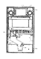
以下、遊技機の一種である回胴式遊技機、具体的にはスロットマシンに適用した場合の第1の実施形態を、図面に基づいて詳細に説明する。図1はスロットマシン10の正面図、図2はスロットマシン10の斜視図、図3はスロットマシン10の前面扉12を開いた状態の斜視図、図4は前面扉12の背面図、図5は筐体11の正面図である。
(First embodiment)
In the following, a first embodiment when applied to a swivel type gaming machine, which is a kind of gaming machine, specifically, a slot machine will be described in detail with reference to the drawings. 1 is a front view of the slot machine 10, FIG. 2 is a perspective view of the slot machine 10, FIG. 3 is a perspective view of the slot machine 10 with the front door 12 opened, FIG. 4 is a rear view of the front door 12, and FIG. FIG. 3 is a front view of the housing 11.

図1〜図5に示すように、スロットマシン10は、その外殻を形成する筐体11を備えている。筐体11は、木製板状に形成された天板11a、底板11b、背板11c、左側板11d及び右側板11eからなり、隣接する各板11a〜11eが接着剤等の固定手段によって固定されることにより、全体として前面を開放した箱状に形成されている。   As shown in FIGS. 1 to 5, the slot machine 10 includes a housing 11 that forms an outer shell thereof. The casing 11 includes a top plate 11a, a bottom plate 11b, a back plate 11c, a left plate 11d, and a right plate 11e formed in a wooden plate shape, and the adjacent plates 11a to 11e are fixed by a fixing means such as an adhesive. As a whole, it is formed in a box shape with the front surface opened.

筐体11の前面側には、前面開閉扉としての前面扉12が開閉可能に取り付けられている。すなわち、筐体11の左側板11dには、上下一対の支軸25a,25bが設けられている。支軸25a,25bは上方に向けて突出された先細り形状の軸部を備えている。一方、前面扉12には、各支軸25a,25bに対応して当該支軸25a,25bの軸部が挿入される挿入孔を備えた支持金具26a,26bが設けられている。そして、各支軸25a,25bの上方に支持金具26a,26bを配置させた上で前面扉12を降下させることにより、支持金具26a,26bの挿入孔に支軸25a,25bの軸部が挿入された状態とされる。これにより、前面扉12は筐体11に対して両支軸25a,25bを結ぶ上下方向へ延びる開閉軸線を中心として回動可能に支持され、その回動によって筐体11の前面開放側を開放したり閉鎖することができるように構成されている。   A front door 12 as a front open / close door is attached to the front side of the housing 11 so as to be openable and closable. In other words, the left side plate 11d of the housing 11 is provided with a pair of upper and lower support shafts 25a and 25b. Each of the support shafts 25a and 25b includes a tapered shaft portion that protrudes upward. On the other hand, the front door 12 is provided with support fittings 26a and 26b having insertion holes into which the shaft portions of the support shafts 25a and 25b are inserted corresponding to the support shafts 25a and 25b. Then, the support brackets 26a and 26b are arranged above the support shafts 25a and 25b, and the front door 12 is lowered, whereby the shaft portions of the support shafts 25a and 25b are inserted into the insertion holes of the support brackets 26a and 26b. It is assumed that it was done. Thereby, the front door 12 is supported so as to be rotatable about an opening / closing axis extending in the vertical direction connecting the both support shafts 25a and 25b with respect to the housing 11, and the front opening side of the housing 11 is opened by the rotation. It can be closed or closed.

前面扉12は、その裏面に設けられた施錠装置によって開放不能な施錠状態とされる。また、前面扉12の右端側上部には解錠操作部たるキーシリンダ20が設けられている。キーシリンダ20は施錠装置と一体化されており、キーシリンダ20に対する所定のキー操作によって前記施錠状態が解除されるように構成されている。   The front door 12 is brought into a locked state that cannot be opened by a locking device provided on the rear surface. Further, a key cylinder 20 serving as an unlocking operation unit is provided at the upper right side of the front door 12. The key cylinder 20 is integrated with a locking device, and is configured such that the locked state is released by a predetermined key operation on the key cylinder 20.

前面扉12の中央部上寄りには、遊技者に遊技状態を報知する遊技パネル30が設けられている。遊技パネル30には、縦長の3つの表示窓31L,31M,31Rが横並びとなるように形成されている。表示窓31L,31M,31Rは透明又は半透明な材質により構成されており、各表示窓31L,31M,31Rを通じてスロットマシン10の内部が視認可能な状態となっている。なお、各表示窓31L,31M,31Rを1つにまとめて共通の表示窓としてもよい。   A game panel 30 for notifying the player of the game state is provided above the center of the front door 12. In the game panel 30, three vertically long display windows 31L, 31M, 31R are formed side by side. The display windows 31L, 31M, 31R are made of a transparent or translucent material, and the inside of the slot machine 10 is visible through the display windows 31L, 31M, 31R. The display windows 31L, 31M, and 31R may be combined into a single display window.

図3に示すように、筐体11は仕切り板40によりその内部が上下2分割されており、仕切り板40の上部には、可変表示手段を構成するリールユニット41が取り付けられている。リールユニット41は、円筒状(円環状)にそれぞれ形成された左リール42L,中リール42M,右リール42Rを備えている。なお、各リール42L,42M,42Rは少なくとも無端状ベルトとして構成されていればよく、円筒状(円環状)に限定されるものではない。各リール42L,42M,42Rは、その中心軸線が当該リールの回転軸線となるように回転可能に支持されている。各リール42L,42M,42Rの回転軸線は略水平方向に延びる同一軸線上に配設され、それぞれのリール42L,42M,42Rが各表示窓31L,31M,31Rと1対1で対応している。従って、各リール42L,42M,42Rの表面の一部はそれぞれ対応する表示窓31L,31M,31Rを通じて視認可能な状態となっている。また、リール42L,42M,42Rが正回転すると、各表示窓31L,31M,31Rを通じてリール42L,42M,42Rの表面は上から下へ向かって移動しているかのように映し出される。   As shown in FIG. 3, the inside of the housing 11 is vertically divided into two by a partition plate 40, and a reel unit 41 constituting variable display means is attached to the upper portion of the partition plate 40. The reel unit 41 includes a left reel 42L, a middle reel 42M, and a right reel 42R each formed in a cylindrical shape (annular shape). The reels 42L, 42M, and 42R may be configured as at least an endless belt, and are not limited to a cylindrical shape (annular shape). Each of the reels 42L, 42M, and 42R is rotatably supported so that the central axis thereof is the rotation axis of the reel. The rotation axes of the reels 42L, 42M, and 42R are arranged on the same axis extending in the substantially horizontal direction, and the reels 42L, 42M, and 42R correspond to the display windows 31L, 31M, and 31R on a one-to-one basis. . Accordingly, a part of the surface of each reel 42L, 42M, 42R is visible through the corresponding display windows 31L, 31M, 31R. Further, when the reels 42L, 42M, and 42R are rotated forward, the surfaces of the reels 42L, 42M, and 42R are projected as if moving from top to bottom through the display windows 31L, 31M, and 31R.

図6は左リール42Lの組立斜視図である。同図に示すように、これら各リール42L,42M,42Rは、それぞれがステッピングモータ61L,61M,61R(図6においては左リール用ステッピングモータ61Lのみ図示)に連結されており、各ステッピングモータ61L,61M,61Rの駆動により各リール42L,42M,42Rが個別に、即ちそれぞれ独立して回転駆動し得る構成となっている。   FIG. 6 is an assembled perspective view of the left reel 42L. As shown in the figure, each of the reels 42L, 42M, and 42R is connected to a stepping motor 61L, 61M, and 61R (only the left reel stepping motor 61L is shown in FIG. 6). , 61M, 61R, the reels 42L, 42M, 42R can be rotated individually, that is, independently.

左リール42Lは、円筒状のかごを形成する円筒骨格部材50と、その外周面において無端状に巻かれた帯状のベルトとを備えている。そして、その巻かれた状態を維持するように、ベルトの長辺両側に沿って形成された一対のシール部を介して円筒骨格部材50に貼付されている。前記ベルトの外周面には、識別情報としての図柄が等間隔ごとに多数印刷されている。円筒骨格部材50の中心部にはボス部51が形成されており、円盤状のボス補強板52を介して左リール用ステッピングモータ61Lの駆動軸に取り付けられている。従って、左リール用ステッピングモータ61Lの駆動軸が回転することによりその駆動軸を中心として円筒骨格部材50が自転するように回転され、左リール42Lが円環状のリール面に沿って周回するようになっている。   The left reel 42L includes a cylindrical skeleton member 50 that forms a cylindrical cage, and a belt-like belt wound endlessly on the outer peripheral surface thereof. And it is affixed on the cylindrical skeleton member 50 through a pair of seal parts formed along the both sides of the long side of the belt so as to maintain the wound state. A large number of symbols as identification information are printed at equal intervals on the outer peripheral surface of the belt. A boss 51 is formed at the center of the cylindrical skeleton member 50, and is attached to the drive shaft of the left reel stepping motor 61L via a disk-like boss reinforcing plate 52. Accordingly, when the drive shaft of the left reel stepping motor 61L is rotated, the cylindrical skeleton member 50 is rotated around the drive shaft so that the left reel 42L circulates along the annular reel surface. It has become.

左リール用ステッピングモータ61Lは、リールユニット41(図3)内において起立状態に配置されたモータプレート53の側面にねじ54で固定されている。モータプレート53には、発光素子55aと受光素子55bとが所定間隔をおいて保持されたリールインデックスセンサ(回転位置検出センサ)55が設置されている。一方、左リール42Lと一体化されたボス補強板52には、半径方向に延びるセンサカットバン56の基端部56bがねじ57で固定されている。このセンサカットバン56の先端部56aは、略直角に屈曲されてリールインデックスセンサ55の両素子55a,55bの間を通過できるように位置合わせがなされている。そして、左リール42Lが1回転するごとにセンサカットバン56の先端部56aの通過をリールインデックスセンサ55が検出し、その検出の都度、後述する主制御装置131に検出信号が出力される。従って、主制御装置131はこの検出信号に基づいて左リール42Lの角度位置を1回転ごとに確認し補正できる。   The left reel stepping motor 61L is fixed to the side surface of the motor plate 53 arranged in an upright state in the reel unit 41 (FIG. 3) with screws 54. The motor plate 53 is provided with a reel index sensor (rotational position detection sensor) 55 in which a light emitting element 55a and a light receiving element 55b are held at a predetermined interval. On the other hand, the base end portion 56b of the sensor cut bun 56 extending in the radial direction is fixed to the boss reinforcing plate 52 integrated with the left reel 42L with a screw 57. The front end portion 56a of the sensor cut bun 56 is bent at a substantially right angle and is positioned so as to pass between both elements 55a and 55b of the reel index sensor 55. Each time the left reel 42L makes one rotation, the reel index sensor 55 detects the passage of the front end portion 56a of the sensor cut bun 56, and a detection signal is output to the main controller 131 described later each time the detection is made. Therefore, main controller 131 can confirm and correct the angular position of left reel 42L for each rotation based on this detection signal.

ステッピングモータ61Lは例えば504パルスの駆動信号(励磁信号あるいは励磁パルスとも言う。以下同じ)を与えることにより1回転されるように設定されており、この励磁パルスによってステッピングモータ61Lの回転位置、すなわち左リール42Lの回転位置が制御される。   The stepping motor 61L is set to rotate once by giving, for example, a drive signal of 504 pulses (also referred to as an excitation signal or an excitation pulse; the same applies hereinafter), and the rotation position of the stepping motor 61L, that is, left The rotational position of the reel 42L is controlled.

各リール42L,42M,42Rの各ベルト上には、その長辺方向(周回方向)に複数個、具体的には21個の図柄が描かれている。従って、所定の位置においてある図柄から次の図柄へ切り替えるには24パルス(=504パルス÷21図柄)を要する。そして、リールインデックスセンサ55の検出信号が出力された時点からのパルス数により、どの図柄が表示窓31L,31M,31Rから視認可能な状態となっているかを認識したり、任意の図柄を表示窓31L,31M,31Rから視認可能な状態としたりする制御を行うことができる。   On each belt of each of the reels 42L, 42M, and 42R, a plurality of, specifically, 21 symbols are drawn in the long side direction (circumferential direction). Therefore, 24 pulses (= 504 pulses ÷ 21 symbols) are required to switch from one symbol to the next symbol at a predetermined position. Based on the number of pulses from when the detection signal of the reel index sensor 55 is output, it is recognized which symbols are visible from the display windows 31L, 31M, and 31R, and arbitrary symbols are displayed on the display window. Control to make it visible from 31L, 31M, 31R can be performed.

各リール42L,42M,42Rに付された図柄のうち、表示窓31L,31M,31Rを介して全体を視認可能な図柄数は、主として表示窓31L,31M,31Rの上下方向の長さによって決定される所定数に限られている。本実施の形態では各リール3個ずつとされている。このため、各リール42L,42M,42Rがすべて停止している状態では、3×3=9個の図柄が遊技者に視認可能な状態となる。   Of the symbols attached to the reels 42L, 42M, and 42R, the number of symbols that can be visually recognized through the display windows 31L, 31M, and 31R is mainly determined by the vertical lengths of the display windows 31L, 31M, and 31R. Is limited to a predetermined number. In this embodiment, three reels are provided. For this reason, when all the reels 42L, 42M, and 42R are stopped, 3 × 3 = 9 symbols are visible to the player.

なお、リールユニット41の各リール42L,42M,42Rは識別情報を可変表示する可変表示手段の一例であり、主表示部を構成する。但し、可変表示手段は、図柄を周方向に可変表示する構成であれば、これ以外の構成であってもよい。例えば、ベルトを自転させるのではなく周回させるタイプ等の他の機械的なリール構成としてもよく、また、機械的なリール構成に加えて、液晶表示器、ドットマトリックス表示器等の電気的表示により識別情報を可変表示させるものを設けてもよく、この場合は表示形態に豊富なバリエーションをもたせることが可能となる。   Each reel 42L, 42M, 42R of the reel unit 41 is an example of variable display means for variably displaying identification information, and constitutes a main display unit. However, the variable display means may have a configuration other than this as long as the symbol is variably displayed in the circumferential direction. For example, other mechanical reel configurations such as a type in which the belt is rotated instead of rotating may be used. In addition to the mechanical reel configuration, an electric display such as a liquid crystal display or a dot matrix display may be used. A device for variably displaying the identification information may be provided, and in this case, it is possible to give abundant variations in the display form.

遊技パネル30には、各表示窓31L,31M,31Rを結ぶようにして、横方向へ平行に3本、斜め方向へたすき掛けに2本、計5本の組合せラインが付されている。勿論、最大組合せライン数を6以上としてもよく、5未満としてもよく、所定条件に応じて最大組合せライン数を変更するようにしてもよい。これら各組合せラインに対応して、表示窓31L,31M,31R群の正面から見て左側には有効ライン表示部32,33,34が設けられている。第1有効ライン表示部32は組合せラインのうち中央の横ライン(中ライン)が有効化された場合に点灯等によって表示報知される。第2有効ライン表示部33は組合せラインのうち上下の横ライン(上ライン及び下ライン)が有効化された場合に点灯等によって表示報知される。第3有効ライン表示部34は組合せラインのうち一対の斜めライン(右下がりライン及び右上がりライン)が有効化された場合に点灯等によって表示報知される。そして、有効化された組合せライン、すなわち有効ライン上に図柄が所定の組合せで停止した場合に入賞となり、予め定められたメダル数の払出処理や、特別遊技状態たるBBゲーム等のボーナスゲームへの移行処理などが実行される。   A total of five combination lines are attached to the game panel 30 such that three display windows 31L, 31M, and 31R are connected to each other and three in parallel in the horizontal direction and two in diagonal directions. Of course, the maximum number of combined lines may be 6 or more, or less than 5, and the maximum number of combined lines may be changed according to a predetermined condition. Corresponding to these combination lines, effective line display sections 32, 33, and 34 are provided on the left side when viewed from the front of the display windows 31L, 31M, and 31R. The first effective line display unit 32 is notified by lighting or the like when the central horizontal line (middle line) of the combination lines is activated. When the upper and lower horizontal lines (upper line and lower line) of the combination lines are activated, the second effective line display unit 33 is displayed and notified by lighting or the like. The third effective line display unit 34 is notified by lighting or the like when a pair of diagonal lines (downward right line and upward right line) of the combination lines is activated. And, when the combination line that has been activated, that is, when the symbol is stopped in a predetermined combination on the activated line, a prize is awarded, and a payout process for a predetermined medal number or a bonus game such as a BB game that is in a special gaming state is awarded. Migration processing etc. are executed.

遊技パネル30の下方左側には、各リール42L,42M,42Rを一斉(同時である必要はない)に回転開始させるために操作されるスタートレバー71が設けられている。スタートレバー71はリール42L,42M,42Rを回転開始、すなわち可変表示を開始させるべく操作される開始操作手段又は始動操作手段を構成する。スタートレバー71は、遊技者がゲームを開始するときに手で押し操作するレバーであり、手が離れたあと元の位置に自動復帰する。メダルが投入されているときにこのスタートレバー52が操作されると、各リール42L,42M,42Rが一斉に回転を始める。   On the lower left side of the game panel 30, a start lever 71 is provided that is operated to start rotation of the reels 42L, 42M, and 42R all at once (not necessarily simultaneously). The start lever 71 constitutes start operation means or start operation means operated to start rotation of the reels 42L, 42M, and 42R, that is, to start variable display. The start lever 71 is a lever that is pushed by the hand when the player starts the game, and automatically returns to the original position after the hand is released. When the start lever 52 is operated while a medal is inserted, the reels 42L, 42M, and 42R start to rotate all at once.

スタートレバー71の右側には、回転している各リール42L,42M,42Rを個別に停止させるために操作されるボタン状のストップスイッチ72,73,74が設けられている。各ストップスイッチ72,73,74は停止対象となるリール42L,42M,42Rに対応する表示窓31L,31M,31Rの直下にそれぞれ配置されている。すなわち、左ストップスイッチ72が操作された場合には左リール42Lの回転が停止し、中ストップスイッチ73が操作された場合には中リール42Mの回転が停止し、右ストップスイッチ74が操作された場合には右リール42Rの回転が停止する。ストップスイッチ72,73,74はリール42L,42M,42Rの回転に基づく可変表示を停止させるべく操作される停止操作手段を構成する。各ストップスイッチ72,73,74は、左リール42Lが回転を開始してから所定時間が経過すると停止させることが可能な状態となり、かかる状態中には図示しないランプが点灯表示されることによって停止操作が可能であることが報知され、回転が停止すると消灯されるようになっている。   On the right side of the start lever 71, button-like stop switches 72, 73, 74 that are operated to individually stop the rotating reels 42L, 42M, 42R are provided. Each of the stop switches 72, 73, 74 is arranged directly below the display windows 31L, 31M, 31R corresponding to the reels 42L, 42M, 42R to be stopped. That is, when the left stop switch 72 is operated, the rotation of the left reel 42L is stopped. When the middle stop switch 73 is operated, the rotation of the middle reel 42M is stopped and the right stop switch 74 is operated. In this case, the rotation of the right reel 42R is stopped. The stop switches 72, 73, 74 constitute stop operation means operated to stop variable display based on the rotation of the reels 42L, 42M, 42R. Each of the stop switches 72, 73, 74 can be stopped when a predetermined time elapses after the left reel 42L starts rotating, and is stopped by lighting a lamp (not shown) during such a state. It is notified that the operation is possible, and is turned off when the rotation stops.

表示窓31L,31M,31Rの下方右側には、遊技媒体としてのメダルを投入するためのメダル投入口75(受入部)が設けられている。メダル投入口75から投入されたメダルは、前面扉12の背面に設けられた通路切替手段としてのセレクタ83によってホッパ用通路81か皿用通路82のいずれかへ導かれる。   On the lower right side of the display windows 31L, 31M, 31R, there is provided a medal slot 75 (accepting part) for inserting medals as game media. The medals inserted from the medal insertion slot 75 are guided to either the hopper passage 81 or the dish passage 82 by the selector 83 as passage switching means provided on the back surface of the front door 12.

ここで、セレクタ83について図7を用いて説明する。図7はセレクタ83の内部構造を説明するための説明図である。なお、図中の2点鎖線は、理解を容易なものとするためにメダルの通過経路を示したものである。   Here, the selector 83 will be described with reference to FIG. FIG. 7 is an explanatory diagram for explaining the internal structure of the selector 83. The two-dot chain line in the figure indicates the medal passage route for easy understanding.

セレクタ83には、メダル投入口75から投入されたメダルをホッパ用通路81へ導くための案内通路84が形成されている。案内通路84は、メダルが1列で通行可能なようにして、図の上端部から右下部にかけて弧を描くような曲線状に形成されている。より詳しくは、セレクタ83を構成するセレクタボディには、図の手前側に突出する突条84aが設けられており、その突条84aが底部を構成するようにして案内通路84が形成されている。案内通路84に到達したメダルは、突条84a上を転がるようにして下流方向へ流れることとなる。   The selector 83 is formed with a guide passage 84 for guiding medals inserted from the medal insertion slot 75 to the hopper passage 81. The guide passage 84 is formed in a curved shape so as to draw an arc from the upper end portion to the lower right portion of the drawing so that medals can pass in one row. More specifically, the selector body constituting the selector 83 is provided with a protrusion 84a protruding toward the front side of the figure, and the guide passage 84 is formed so that the protrusion 84a forms the bottom. . The medal that has reached the guide passage 84 flows in the downstream direction so as to roll on the protrusion 84a.

セレクタ83は、案内通路84の上流側にあるメダルを皿用通路82へ排出するための通路切替片85を備えている。通路切替片85は、案内通路84の上流側において当該案内通路84内に出没可能に設けられている。また、通路切替片85は、図示しないソレノイドに連結されており、ソレノイドの非励磁時には案内通路84内に通路切替片85が突出する。この場合、案内通路84の上流側にあるメダルはその突出した通路切替片85に当たることで突条84aを乗り上げて下方に落下し、皿用通路82に導かれる。皿用通路82に導かれたメダルは、前面扉12の前面下部に設けられたメダル排出口17からメダル受け皿18へと導かれ、遊技者に返還される。一方、ソレノイドの励磁時には案内通路84外に通路切替片85が没する。これにより、メダルは案内通路84に沿って流れ、ホッパ用通路81に導かれる。ホッパ用通路81に導かれたメダルは、筐体11の内部に収納されたホッパ装置91へと導かれる。   The selector 83 includes a passage switching piece 85 for discharging medals located upstream of the guide passage 84 to the tray passage 82. The passage switching piece 85 is provided on the upstream side of the guide passage 84 so as to appear in the guide passage 84. The passage switching piece 85 is connected to a solenoid (not shown), and the passage switching piece 85 projects into the guide passage 84 when the solenoid is not excited. In this case, the medal on the upstream side of the guide passage 84 hits the protruding passage switching piece 85, rides on the protrusion 84a, falls downward, and is guided to the tray passage 82. The medal guided to the tray passage 82 is guided to the medal tray 18 from the medal discharge port 17 provided at the lower front portion of the front door 12 and returned to the player. On the other hand, the passage switching piece 85 is immersed outside the guide passage 84 when the solenoid is excited. Thereby, the medal flows along the guide passage 84 and is guided to the hopper passage 81. The medal guided to the hopper passage 81 is guided to the hopper device 91 housed in the housing 11.

また、セレクタ83において通路切替片85の下流側には、案内通路84を通過するメダルを検出するための投入メダル検出装置86が設けられている。メダル検出装置86は、フォトセンサからなる第1投入メダル検出センサ86aと同じくフォトセンサからなる第2投入メダル検出センサ86bとを備え、これら各検出センサ86a,86bは案内通路84の流下方向に並ぶようにして近接配置されている(少なくとも1時期において同一メダルを同時に検出する状態が生じる程度の近接状態とする)。これら各検出センサ86a,86bにより案内通路84のメダルの通過が順次検出される。   In addition, a selector medal detection device 86 for detecting a medal passing through the guide passage 84 is provided on the downstream side of the passage switching piece 85 in the selector 83. The medal detection device 86 includes a first inserted medal detection sensor 86a made of a photosensor and a second inserted medal detection sensor 86b made of a photosensor, and these detection sensors 86a, 86b are arranged in the flow-down direction of the guide passage 84. Thus, they are arranged close to each other (the proximity state is such that a state in which the same medal is simultaneously detected at least at one time is generated). These detection sensors 86a and 86b sequentially detect the passage of medals in the guide passage 84.

メダルを遊技者に付与する排出手段としてのホッパ装置91は、メダルを貯留する貯留タンク92と、メダルを遊技者に払い出す払出装置93とより構成されている。払出装置93は、図示しないメダル払出用回転板を回転させることにより、皿用通路82の中央右部に設けられた開口94へメダルを排出し、皿用通路82を介してメダル受け皿18へメダルを払い出すようになっている。また、ホッパ装置91の右方には、貯留タンク92内に所定量以上のメダルが貯留されることを回避するための予備タンク95が設けられている。ホッパ装置91の貯留タンク92内部には、この貯留タンク92から予備タンク95へとメダルを排出する誘導プレート96が設けられている。したがって、誘導プレート96が設けられた高さ以上にメダルが貯留された場合、かかるメダルが予備タンク95に貯留されることとなる。   The hopper device 91 serving as a discharging means for giving a medal to the player is configured by a storage tank 92 for storing the medal and a payout device 93 for paying out the medal to the player. The payout device 93 rotates a medal payout rotating plate (not shown) to discharge the medal to the opening 94 provided in the central right portion of the tray passage 82 and to the medal tray 18 through the tray passage 82. To come out. Further, a reserve tank 95 is provided on the right side of the hopper device 91 in order to avoid storing a predetermined amount or more of medals in the storage tank 92. A guide plate 96 for discharging medals from the storage tank 92 to the reserve tank 95 is provided inside the storage tank 92 of the hopper device 91. Therefore, when medals are stored more than the height at which the guide plate 96 is provided, the medals are stored in the reserve tank 95.

メダル投入口75の下方には、ボタン状の返却スイッチ76が設けられている。返却スイッチ76は、メダル投入口75に投入されたメダルがセレクタ83内に詰まった際に押されるスイッチであり、このスイッチが押されることによりセレクタ83が機械的に連動して動作され、当該セレクタ83内に詰まったメダルがメダル排出口17より返却されるようになっている。   A button-like return switch 76 is provided below the medal slot 75. The return switch 76 is a switch that is pressed when a medal inserted into the medal insertion slot 75 is jammed in the selector 83. When this switch is pressed, the selector 83 is mechanically operated to operate the selector 83. The medals packed in 83 are returned from the medal discharge port 17.

表示窓31L,31M,31Rの下方左側には、仮想遊技媒体としてのクレジットされた仮想メダルを一度に3枚投入するためのボタン状の第1クレジット投入スイッチ77が設けられている。また、第1クレジット投入スイッチ77の左方には当該スイッチ77よりも小さなボタン状のスイッチとして、第2クレジット投入スイッチ78及び第3クレジット投入スイッチ79が設けられている。第2クレジット投入スイッチ78はクレジットされた仮想メダルを一度に2枚投入するためのものであり、第3クレジット投入スイッチ79は仮想メダルを1枚投入するためのものである。   On the lower left side of the display windows 31L, 31M, 31R, there is provided a button-like first credit insertion switch 77 for inserting three credited virtual medals as virtual game media at a time. Further, on the left side of the first credit insertion switch 77, a second credit insertion switch 78 and a third credit insertion switch 79 are provided as button switches smaller than the switch 77. The second credit insertion switch 78 is for inserting two credited virtual medals at a time, and the third credit insertion switch 79 is for inserting one virtual medal.

スタートレバー71の左側には、ボタン状の精算スイッチ80が設けられている。すなわち、本スロットマシン10では、所定の最大値(メダル50枚分)となるまでの余剰の投入メダルや入賞時の獲得メダルを仮想メダルとして貯留記憶するクレジット機能を有しており、仮想メダルが貯留記憶されている状態で精算スイッチ80が押下操作されることで、仮想メダルが現実のメダルとして排出される。   A button-like settlement switch 80 is provided on the left side of the start lever 71. That is, the slot machine 10 has a credit function for storing and storing surplus inserted medals up to a predetermined maximum value (for 50 medals) and winning medals as virtual medals. The virtual medal is ejected as an actual medal by pressing the settlement switch 80 in the stored and stored state.

遊技パネル30の表示窓31L,31M,31Rの下方には、貯留記憶された仮想メダル数を表示するクレジット表示部35と、入賞時に獲得したメダルの枚数を表示する獲得枚数表示部36とがそれぞれ設けられている。   Below the display windows 31L, 31M, and 31R of the game panel 30, there are a credit display unit 35 that displays the number of virtual medals stored and stored, and an acquired number display unit 36 that displays the number of medals earned at the time of winning. Is provided.

ここで、メダルがベットされる手順について説明する。遊技の開始時にメダル投入口75からメダルが投入されるとベットとなる。   Here, a procedure for betting medals will be described. If a medal is inserted from the medal slot 75 at the start of the game, a bet is placed.

すなわち、1枚目のメダルがメダル投入口75に投入されると、第1有効ライン表示部32が点灯し、そしてこれに対応する中ラインが有効ラインとなり、2枚目のメダルがメダル投入口75に投入されると、更に第2有効ライン表示部33が点灯すると共に、これに対応する上ライン及び下ラインを含む合計3本の組合せラインがそれぞれ有効ラインとなり、3枚目のメダルがメダル投入口75に投入されると、更に第3有効ライン表示部34が点灯し、そしてこれに対応する一対の斜めラインを含む合計5本の組合せライン全てが有効ラインとなる。   That is, when the first medal is inserted into the medal insertion slot 75, the first effective line display section 32 is turned on, and the corresponding middle line becomes the effective line, and the second medal is the medal insertion slot. When the number 75 is inserted, the second effective line display section 33 is turned on, and a total of three combination lines including the upper line and the lower line corresponding to the second effective line display section 33 become effective lines, respectively, and the third medal is a medal. When it is inserted into the insertion port 75, the third effective line display unit 34 is further turned on, and a total of five combination lines including a pair of diagonal lines corresponding thereto become effective lines.

また、4枚以上のメダルがメダル投入口75に投入されると、3枚を超える余剰メダルは、そのときに貯留記憶されている仮想メダルが50枚未満であれば、スロットマシン内部に貯蓄されると共にクレジット表示部35の仮想メダル数が加算表示される。一方、仮想メダル数が50枚のとき又は50枚に達したときには、セレクタ83によりホッパ用通路81から皿用通路82への切替がなされ、メダル排出口17からメダル受け皿18へと余剰メダルが返却される。   When four or more medals are inserted into the medal slot 75, surplus medals exceeding three are stored inside the slot machine if the number of virtual medals stored and stored at that time is less than 50. At the same time, the number of virtual medals on the credit display unit 35 is added and displayed. On the other hand, when the number of virtual medals is 50 or reaches 50, the selector 83 switches from the hopper passage 81 to the tray passage 82, and the surplus medals are returned from the medal outlet 17 to the medal tray 18. Is done.

また、クレジット表示部35に貯留枚数が表示されている場合には、第1〜第3クレジット投入スイッチ77〜79のいずれかが押された際にも仮想メダルが投入されたこととなりベットとなる。   Further, when the stored number is displayed on the credit display unit 35, a virtual medal is inserted even when any of the first to third credit insertion switches 77 to 79 is pressed, and a bet is made. .

第3クレジット投入スイッチ79が押された際には、仮想メダルが1枚投入されたこととしてクレジット表示部35に表示されている数値が1つ減算され、第1有効ライン表示部32が点灯して中ラインが有効ラインとなる。第2クレジット投入スイッチ78が押された際には、仮想メダルが2枚投入されたこととしてクレジット表示部35に表示されている数値が2つ減算され、第1有効ライン表示部32および第2有効ライン表示部33が点灯して合計3本の組合せラインが有効ラインとなる。第1クレジット投入スイッチ77が押された際には、仮想メダルが3枚投入されたこととしてクレジット表示部35に表示されている数値が3つ減算され、全ての有効ライン表示部32〜34が点灯して合計5本の組合せラインが有効ラインとなる。   When the third credit insertion switch 79 is pressed, the numerical value displayed on the credit display unit 35 is decremented by one as a virtual medal is inserted, and the first effective line display unit 32 is turned on. The middle line becomes the active line. When the second credit insertion switch 78 is pressed, two numerical values displayed on the credit display unit 35 as two virtual medals are inserted are subtracted, and the first valid line display unit 32 and the second The effective line display unit 33 is turned on, and a total of three combination lines become effective lines. When the first credit insertion switch 77 is pressed, three numerical values displayed on the credit display unit 35 are subtracted as three virtual medals are inserted, and all the effective line display units 32 to 34 are displayed. Lights up and a total of five combination lines become effective lines.

なお、第1〜第3クレジット投入スイッチ77〜79のいずれかが押された際に投入されるべき仮想メダルが貯留されていない場合、例えばクレジット表示部35の表示が2のときに第1クレジット投入スイッチ77が押された場合等には、クレジット表示部35の数値が全て減算されて0となり、投入可能な仮想メダル分だけベットされる。   In addition, when the virtual medal to be inserted when any of the first to third credit insertion switches 77 to 79 is pressed is not stored, for example, when the display of the credit display unit 35 is 2, the first credit For example, when the insertion switch 77 is pressed, all the numerical values in the credit display unit 35 are subtracted to 0, and a bet is placed for the virtual medal that can be inserted.

前面扉12の上部には、遊技の進行に伴い点灯したり点滅したりする上部ランプ13と、遊技の進行に伴い種々の効果音を鳴らしたり、遊技者に遊技状態を報知したりする左右一対のスピーカ14と、遊技者に各種情報を与える補助表示部15とが設けられている。補助表示部15は、本実施の形態では表示内容の多様化及び表示演出の重厚化を意図して液晶表示器によって構成されているが、ドットマトリックス表示器等の他の表示器を使用してもよい。補助表示部15は、遊技の進行に伴って各種表示演出を実行するためのものであり、各リール42L,42M,42Rによる遊技を主表示部によるものと考えることができることから、本実施の形態では補助表示部15と称している。補助表示部15の背面には上部ランプ13やスピーカ14、補助表示部15を駆動させるための表示制御装置111が設けられている。なお、上部ランプ13及びスピーカ14の位置や数は特に以上説明したものに限られない。   On the upper part of the front door 12, there are an upper lamp 13 that lights up or flashes as the game progresses, and a pair of left and right sounds that make various sound effects as the game progresses and inform the player of the game state Speaker 14 and an auxiliary display unit 15 for giving various information to the player. In the present embodiment, the auxiliary display unit 15 is configured by a liquid crystal display for the purpose of diversifying display contents and increasing the amount of display effect. Also good. The auxiliary display unit 15 is for executing various display effects as the game progresses, and it can be considered that the game by the reels 42L, 42M, and 42R is caused by the main display unit. The auxiliary display unit 15 is referred to. On the back surface of the auxiliary display unit 15, an upper lamp 13, a speaker 14, and a display control device 111 for driving the auxiliary display unit 15 are provided. The positions and numbers of the upper lamp 13 and the speakers 14 are not limited to those described above.

筐体11の内部においてホッパ装置91の左方には、電源ボックス121が設けられている。電源ボックス121は、電源スイッチ122、リセットスイッチ123、及び当選確率設定キー挿入孔124などを備えている。電源スイッチ122は、主制御装置131を始めとする各部に電源を供給するための起動スイッチである。リセットスイッチ123は、スロットマシン10のエラー状態をリセットするためのスイッチである。当選確率設定キー挿入孔124は、ホール管理者などがメダルの出玉調整を行うためのものである。すなわち、ホール管理者等が当選確率設定キーを当選確率設定キー挿入孔124へ挿入してON操作することにより、スロットマシン10の当選確率を設定できるようになっている。   A power supply box 121 is provided on the left side of the hopper device 91 inside the housing 11. The power supply box 121 includes a power switch 122, a reset switch 123, a winning probability setting key insertion hole 124, and the like. The power switch 122 is a start switch for supplying power to each unit including the main controller 131. The reset switch 123 is a switch for resetting an error state of the slot machine 10. The winning probability setting key insertion hole 124 is used by a hole manager or the like to adjust the appearance of medals. That is, the hall manager or the like can set the winning probability of the slot machine 10 by inserting the winning probability setting key into the winning probability setting key insertion hole 124 and turning it ON.

リールユニット41の上方には、主制御装置131が筐体11の背板11cに取り付けられている。主制御装置131は、主たる制御を司るCPU、遊技プログラムを記憶したROM、遊技の進行に応じた必要なデータを一時的に記憶するRAM、各種機器との連絡をとるポート、時間計数や同期を図る場合などに使用されるクロック回路等を含む主基板を具備しており、主基板が透明樹脂材料等よりなる被包手段としての基板ボックスに収容されて構成されている。基板ボックスは、略直方体形状のボックスベースと該ボックスベースの開口部を覆うボックスカバーとを備えている。これらボックスベースとボックスカバーとは封印手段としての封印ユニットによって開封不能に連結され、これにより基板ボックスが封印されている。   A main controller 131 is attached to the back plate 11 c of the housing 11 above the reel unit 41. The main control device 131 includes a CPU that controls the main control, a ROM that stores a game program, a RAM that temporarily stores necessary data according to the progress of the game, a port that communicates with various devices, time counting and synchronization. A main board including a clock circuit and the like used in the case of planning is provided, and the main board is accommodated in a board box as an encapsulating means made of a transparent resin material or the like. The board box includes a substantially rectangular parallelepiped box base and a box cover that covers an opening of the box base. The box base and the box cover are connected to each other so as not to be opened by a sealing unit as a sealing means, whereby the substrate box is sealed.

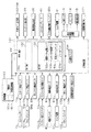
次に、本スロットマシン10の電気的構成について、図8のブロック図に基づいて説明する。   Next, the electrical configuration of the slot machine 10 will be described based on the block diagram of FIG.

主制御装置131には、演算処理手段であるCPU151を中心とするマイクロコンピュータが搭載されている。CPU151には、電源ボックス121の内部に設けられた電源装置161の他に、所定の上限値の範囲内で乱数を生成し適宜更新する乱数カウンタ154などが内部バスを介して接続されている。かかる主制御装置131は、スロットマシン10に内蔵されるメイン基盤としての機能を果たすものである。また、主制御装置131には、図示しない入出力ポートが設けられており、当該入出力ポートを介して各種信号の入出力が行われる。   The main control device 131 is equipped with a microcomputer centering on a CPU 151 as arithmetic processing means. In addition to the power supply device 161 provided in the power supply box 121, the CPU 151 is connected to a random number counter 154 that generates a random number within a predetermined upper limit range and appropriately updates it, and the like via an internal bus. The main control device 131 functions as a main base incorporated in the slot machine 10. The main controller 131 is provided with an input / output port (not shown), and various signals are input / output through the input / output port.

すなわち、主制御装置131の入力側には、スタートレバー71の操作を検出するスタート検出センサ71a、各ストップスイッチ72,73,74の操作を個別に検出するストップ検出センサ72a,73a,74a、メダル投入口75から投入されたメダルを検出する第1,第2投入メダル検出センサ86a,86b、各クレジット投入スイッチ77,78,79の操作を個別に検出するクレジット投入検出センサ77a,78a,79a、精算スイッチ80の操作を検出する精算検出センサ80a、ホッパ装置91から払い出されるメダルを検出する払出検出センサ91a、リセットスイッチ123の操作を検出するリセット検出センサ123a、当選確率設定キー挿入孔124に当選確率設定キーが挿入されてON操作されたことを検出する当選確率設定キー検出センサ124a等の各種センサが接続されており、これら各種センサからの信号は入出力ポートを介してCPU151へ出力されるようになっている。   That is, on the input side of the main controller 131, a start detection sensor 71a that detects the operation of the start lever 71, stop detection sensors 72a, 73a, and 74a that individually detect the operations of the stop switches 72, 73, and 74, medals First and second inserted medal detection sensors 86a and 86b for detecting medals inserted from the insertion slot 75, and credit insertion detection sensors 77a, 78a and 79a for individually detecting operations of the respective credit insertion switches 77, 78 and 79; The payment detection sensor 80a for detecting the operation of the payment switch 80, the payout detection sensor 91a for detecting the medal paid out from the hopper device 91, the reset detection sensor 123a for detecting the operation of the reset switch 123, and the winning probability setting key insertion hole 124 are won. Check that the probability setting key was inserted and turned ON. Various sensors such as winning probability setting key detection sensor 124a for output is connected, and the signal from these various sensors are outputted to the CPU151 through the input and output ports.

また、主制御装置131の入力側には、電源装置161に設けられた停電監視回路161bが接続されている。電源装置161には、主制御装置131を始めとしてスロットマシン10の各電子機器に駆動電力を供給する電源部161aや、上述した停電監視回路161bなどが搭載されている。   Further, a power failure monitoring circuit 161 b provided in the power supply device 161 is connected to the input side of the main control device 131. The power supply device 161 includes a power supply unit 161 a that supplies driving power to the electronic devices of the slot machine 10 including the main control device 131, the power failure monitoring circuit 161 b described above, and the like.

停電監視回路161bは電源の遮断状態を監視し、停電時はもとより、電源スイッチ122による電源遮断時に停電信号を生成するためのものである。そのため停電監視回路161bは、電源部161aから出力されるこの例では直流12ボルトの安定化駆動電圧を監視し、この駆動電圧が例えば10ボルト未満まで低下したとき電源が遮断されたものと判断して停電信号が出力されるように構成されている。停電信号はCPU151に供給され、CPU151ではこの停電信号を認識することにより後述する停電時処理が実行される。   The power failure monitoring circuit 161b is for monitoring the power-off state and generating a power failure signal not only at the time of power failure but also at the time of power-off by the power switch 122. For this reason, the power failure monitoring circuit 161b monitors the stabilized drive voltage of 12 VDC in this example output from the power supply unit 161a, and determines that the power supply is shut off when the drive voltage drops below, for example, 10 volts. Power outage signal is output. The power failure signal is supplied to the CPU 151, and the CPU 151 recognizes this power failure signal and executes a power failure process described later.

電源部161aは、出力電圧が10ボルト未満まで低下した場合でも、主制御装置131などの制御系における駆動電圧として使用される5ボルトの安定化電圧が出力されるように構成されている。この安定化電圧が出力される時間としては、主制御装置131による停電時処理を実行するに十分な時間が確保されている。   The power supply unit 161a is configured to output a stabilized voltage of 5 volts used as a drive voltage in a control system such as the main control device 131 even when the output voltage is reduced to less than 10 volts. As a time for outputting the stabilization voltage, a time sufficient for executing the power failure process by the main controller 131 is secured.

主制御装置131の出力側には、各有効ライン表示部32,33,34、クレジット表示部35、獲得枚数表示部36、各リール42L,42M,42Rを回転させるための各ステッピングモータ61(61L,61M,61R)、セレクタ83に設けられたメダル通路切替ソレノイド83a、ホッパ装置91、表示制御装置111、図示しないホール管理装置などに情報を送信できる外部集中端子板171等が接続されている。   On the output side of the main controller 131, each of the effective line display units 32, 33, 34, the credit display unit 35, the acquired number display unit 36, and each stepping motor 61 (61L for rotating each reel 42L, 42M, 42R). , 61M, 61R), a medal passage switching solenoid 83a provided in the selector 83, a hopper device 91, a display control device 111, an external concentration terminal plate 171 capable of transmitting information to a hall management device (not shown), and the like.

表示制御装置111は、上部ランプ13やスピーカ14、補助表示部15を駆動させるための制御装置であり、これらを駆動させるためのCPU、ROM、RAM等が一体化された基板を備えている。そして、主制御装置131からの信号を受け取った上で、表示制御装置111が独自に上部ランプ13、スピーカ14及び補助表示部15を駆動制御する。従って、表示制御装置111は、遊技を統括管理するメイン基盤たる主制御装置131との関係では補助的な制御を実行するサブ基盤となっている。即ち、間接的な遊技に関する音声やランプ、表示についてはサブ基盤を設けることにより、メイン基盤の負担軽減を図っている。なお、各種表示部32〜36を表示制御装置111が制御する構成としてもよい。   The display control device 111 is a control device for driving the upper lamp 13, the speaker 14, and the auxiliary display unit 15, and includes a substrate in which a CPU, a ROM, a RAM, and the like for driving these are integrated. Then, after receiving a signal from the main control device 131, the display control device 111 independently drives and controls the upper lamp 13, the speaker 14, and the auxiliary display unit 15. Therefore, the display control device 111 is a sub-base that executes auxiliary control in relation to the main control device 131 that is a main base that manages and manages games. In other words, the sub-base is provided for voice, lamp, and display related to indirect games, thereby reducing the burden on the main base. In addition, it is good also as a structure which the display control apparatus 111 controls the various display parts 32-36.

上述したCPU151には、このCPU151によって実行される各種の制御プログラム、及び後述する監視タイマカウンタ153cにセットする値やエラーカウンタ154dにセットする値といった固定値データを記憶したROM152と、このROM152内に記憶されている制御プログラムを実行するに当たって各種のデータを一時的に記憶する作業エリアを確保するためのRAM153のほかに、図示はしないが周知のように割込み回路を始めとしてタイマ回路、データ送受信回路などスロットマシン10において必要な各種の処理回路などが内蔵されている。ROM152とRAM153によって記憶手段としてのメインメモリが構成されている。   The CPU 151 described above stores various control programs executed by the CPU 151, ROM 152 storing fixed value data such as a value set in a later-described monitoring timer counter 153 c and a value set in the error counter 154 d, and in this ROM 152 In addition to the RAM 153 for securing a work area for temporarily storing various data when executing the stored control program, a timer circuit, a data transmission / reception circuit such as an interrupt circuit, as is well known, although not shown. Various processing circuits necessary for the slot machine 10 are incorporated. The ROM 152 and RAM 153 constitute a main memory as storage means.

RAM153について詳細に説明すると、RAM153には、各種のデータを一時的に記憶するためのメモリや、停電などの発生により電源が遮断された場合において、電源遮断時(電源スイッチ122の操作による電源遮断をも含む。以下同様)のスタックポインタの値を記憶しておくためのバックアップエリアが設けられている。なお、CPU151のNMI端子(ノンマスカブル割込端子)には、停電等の発生による電源遮断時に、停電監視回路161bからの停電信号が入力されるように構成されており、停電等の発生に伴う停電フラグ生成処理としてのNMI割込み処理が即座に実行される。   The RAM 153 will be described in detail. The RAM 153 has a memory for temporarily storing various data, and when the power is shut down due to the occurrence of a power failure or the like, the power is shut down (the power is shut down by operating the power switch 122 A backup area for storing the stack pointer value is also provided. Note that a power failure signal from the power failure monitoring circuit 161b is input to the NMI terminal (non-maskable interrupt terminal) of the CPU 151 when the power is interrupted due to the occurrence of a power failure or the like. NMI interrupt processing as flag generation processing is immediately executed.

また、RAM153には、仮想メダルを貯留記憶するための仮想メダル記憶エリア153a、ベットされたメダルの枚数(賭け数)を記憶するためのベットメダル記憶エリア153bや、後述する投入タイミング監視処理(図22)にて異常を判定する上で用いられる監視タイマカウンタ153c及びエラーカウンタ154dなどの各種カウンタエリアが設けられている。なお、仮想メダル記憶エリア153aにおける貯留記憶可能な最大仮想メダル枚数は50枚となっており、ベットメダル記憶エリア153bにおける記憶可能な最大ベット枚数は3枚となっている。   Further, the RAM 153 stores a virtual medal storage area 153a for storing and storing virtual medals, a bet medal storage area 153b for storing the number of bets (the number of bets), and an insertion timing monitoring process (described later). In 22), various counter areas such as a monitoring timer counter 153c and an error counter 154d used for determining an abnormality are provided. The maximum number of virtual medals that can be stored and stored in the virtual medal storage area 153a is 50, and the maximum number of bets that can be stored in the bet medal storage area 153b is 3.

続いて、主制御装置131内のCPU151により実行される各制御処理を図9〜図26のフローチャート等を参照しながら説明する。かかるCPU151の処理としては大別して、電源投入に伴い起動されるメイン処理と、定期的に(本実施の形態では1.49msec周期で)起動されるタイマ割込み処理と、NMI端子(ノンマスカブル端子)への停電信号の入力により起動されるNMI割込み処理とがあり、説明の便宜上、はじめにNMI割込み処理とタイマ割込み処理とを説明し、その後メイン処理を説明する。   Next, each control process executed by the CPU 151 in the main controller 131 will be described with reference to the flowcharts in FIGS. The processing of the CPU 151 is broadly divided into a main processing that is started when the power is turned on, a timer interrupt processing that is started periodically (in a cycle of 1.49 msec in the present embodiment), and an NMI terminal (non-maskable terminal). For convenience of explanation, the NMI interrupt process and the timer interrupt process will be described first, and then the main process will be described.

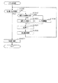
図9はNMI割込み処理の一例を示すフローチャートである。停電の発生などによって電源が遮断されると、電源装置161の停電監視回路161bでは停電信号が生成され、主制御装置131に対して出力される。NMI端子を介して停電信号を受信した主制御装置131では、NMI割込み処理が実行される。   FIG. 9 is a flowchart showing an example of the NMI interrupt process. When the power is shut off due to the occurrence of a power failure or the like, the power failure monitoring circuit 161b of the power supply device 161 generates a power failure signal and outputs it to the main controller 131. In the main controller 131 that has received the power failure signal via the NMI terminal, NMI interrupt processing is executed.

NMI割込み処理では、まずステップS101において、CPU151内に設けられた使用レジスタのデータをRAM153内に設けられたバックアップエリアに退避させる。続いて、ステップS102では、停電フラグをRAM153内に設けられた停電フラグ格納エリアにセットする。その後、ステップS103にてRAM153のバックアップエリアに退避させたデータを再びCPU151の使用レジスタに復帰させる。この復帰処理でNMI割込み処理が終了する。   In the NMI interrupt processing, first, in step S 101, the data of the used register provided in the CPU 151 is saved in the backup area provided in the RAM 153. Subsequently, in step S102, the power failure flag is set in a power failure flag storage area provided in the RAM 153. Thereafter, the data saved in the backup area of the RAM 153 in step S103 is restored to the use register of the CPU 151 again. With this return processing, the NMI interrupt processing ends.

図10は、主制御装置131で定期的に実行されるタイマ割込み処理のフローチャートであり、主制御装置131のCPU151により例えば1.49msecごとにタイマ割込みが発生する。   FIG. 10 is a flowchart of a timer interrupt process periodically executed by the main controller 131. A timer interrupt is generated by the CPU 151 of the main controller 131 every 1.49 msec, for example.

先ず、ステップS201に示すレジスタ退避処理では、後述する通常処理で使用しているCPU151内の全レジスタの値をRAM153のバックアップエリアに退避させる。ステップS202では停電フラグがセットされているか否かを確認し、停電フラグがセットされているときにはステップS203に進み、停電時処理を実行する。   First, in the register saving process shown in step S201, the values of all the registers in the CPU 151 used in the normal process described later are saved in the backup area of the RAM 153. In step S202, it is confirmed whether or not a power failure flag is set. If the power failure flag is set, the process proceeds to step S203, and a power failure process is executed.

ここで、停電時処理について図11を用いて説明する。ステップS301では、コマンド送信が終了しているか否かを判定する。送信が終了していない場合には本処理を終了してタイマ割込み処理に復帰し、コマンド送信を終了させる。ステップS301がYES、すなわちコマンドの送信が完了している場合には、ステップS302に進み、CPU151のスタックポインタの値をRAM153内のバックアップエリアに保存する。その後ステップS303では、停止処理として後述するRAM判定値をクリアすると共に入出力ポートにおける出力ポートの出力状態をクリアし、図示しない全てのアクチュエータをオフ状態にする。ステップS304では、RAM判定値を算出し、バックアップエリアに保存する。RAM判定値とは、具体的にはRAM153の作業領域アドレスにおけるチェックサムの2の補数である。RAM判定値をバックアップエリアに保存することにより、RAM153のチェックサムは0となる。RAM153のチェックサムを0とすることにより、ステップS305においてそれ以後のRAMアクセスを禁止する。その後は、電源が完全に遮断して処理が実行できなくなるのに備え、無限ループに入る。   Here, the power failure process will be described with reference to FIG. In step S301, it is determined whether command transmission has been completed. If the transmission has not been completed, this process is terminated and the process returns to the timer interrupt process to terminate the command transmission. If step S301 is YES, that is, if the command transmission is completed, the process proceeds to step S302, and the value of the stack pointer of the CPU 151 is stored in the backup area in the RAM 153. Thereafter, in step S303, a RAM determination value, which will be described later, is cleared as a stop process, and the output state of the output port in the input / output port is cleared, and all actuators (not shown) are turned off. In step S304, a RAM determination value is calculated and stored in the backup area. The RAM determination value is specifically a 2's complement of the checksum at the work area address of the RAM 153. By storing the RAM determination value in the backup area, the checksum of the RAM 153 becomes zero. By setting the checksum of the RAM 153 to 0, subsequent RAM access is prohibited in step S305. After that, an infinite loop is entered in preparation for the case where the power supply is completely shut down and processing cannot be executed.

タイマ割込み処理の説明に戻り、ステップS202にて停電フラグがセットされていない場合には、ステップS204以降の各種処理を行う。   Returning to the description of the timer interrupt process, if the power failure flag is not set in step S202, various processes after step S204 are performed.

すなわち、ステップS204では、誤動作の発生を監視するためのウオッチドッグタイマの値を初期化するウオッチドッグタイマのクリア処理を行う。ステップS205では、CPU151自身に対して次回のタイマ割込みを設定可能とする割込み終了宣言処理を行う。ステップS206では、各リール42L,42M,42Rを回転させるために、それぞれの回胴駆動モータであるステッピングモータ61L〜61Rを駆動させるステッピングモータ制御処理を行う。ステップS207では、入出力ポートに接続された各種センサ(図8参照)の状態を読み込むと共に、読み込み結果が正常か否かを監視するセンサ監視処理を行う。   That is, in step S204, a watchdog timer clearing process for initializing the value of the watchdog timer for monitoring the occurrence of malfunction is performed. In step S205, an interrupt end declaration process is performed to enable the next timer interrupt to be set for the CPU 151 itself. In step S206, in order to rotate the reels 42L, 42M, and 42R, a stepping motor control process for driving the stepping motors 61L to 61R, which are the respective rotary drive motors, is performed. In step S207, the state of various sensors (see FIG. 8) connected to the input / output port is read, and sensor monitoring processing is performed to monitor whether the reading result is normal.

ステップS208では、各タイマの値の減算等を行うタイマ演算処理を行う。ステップS209では、メダルのベット数や、払い出し枚数をカウントした結果を外部集中端子板171へ出力するカウンタ処理を行う。ステップS210では、各種コマンドを表示制御装置111へ送信するコマンド出力処理を行う。ステップS211では、セグメントデータを設定するセグメントデータ設定処理を行う。ステップS212では、セグメントデータ設定処理で設定されたセグメントデータを所定の表示部に供給して該当する数字、記号などを表示するセグメントデータ表示処理を行う。ステップS213では、I/O装置に対応するデータを出力するポート出力処理を行う。ステップS214では、先のステップS201にてバックアップエリアに退避させた各レジスタの値をそれぞれCPU151内の対応するレジスタに復帰させる。その後ステップS215にて次回のタイマ割込みを許可する割込み許可処理を行い、この一連のタイマ割込み処理を終了する。   In step S208, timer calculation processing for subtracting the value of each timer is performed. In step S209, a counter process for outputting the bet number of medals and the result of counting the number of payouts to the external concentration terminal board 171 is performed. In step S210, command output processing for transmitting various commands to the display control device 111 is performed. In step S211, segment data setting processing for setting segment data is performed. In step S212, segment data display processing is performed in which the segment data set in the segment data setting processing is supplied to a predetermined display unit and corresponding numbers, symbols, and the like are displayed. In step S213, port output processing for outputting data corresponding to the I / O device is performed. In step S214, the value of each register saved in the backup area in the previous step S201 is restored to the corresponding register in the CPU 151. Thereafter, in step S215, an interrupt permission process for permitting the next timer interrupt is performed, and this series of timer interrupt processes is terminated.

図12は電源投入後に実行される主制御装置131でのメイン処理を示すフローチャートである。メイン処理は、停電からの復旧や電源スイッチ122のオン操作によって電源が投入された際に実行される。   FIG. 12 is a flowchart showing a main process in the main controller 131 executed after the power is turned on. The main process is executed when the power is turned on by recovery from a power failure or by turning on the power switch 122.

先ずステップS401では、初期化処理として、スタックポインタの値をCPU151内に設定すると共に、割込み処理を許可する割込みモードを設定し、その後CPU151内のレジスタ群や、I/O装置等に対する各種の設定などを行う。   First, in step S401, as initialization processing, the value of the stack pointer is set in the CPU 151, and an interrupt mode that permits interrupt processing is set. Thereafter, various settings for the register group in the CPU 151, the I / O device, and the like are set. Etc.

これらの初期化処理が終了すると、ステップS402では当選確率設定キーが当選確率設定キー挿入孔124に挿入されてON操作されているか否か、より詳しくは当選確率設定キー検出センサ124aからON信号を受信しているか否かを判定する。当選確率設定キーのON操作がなされている場合にはステップS403に進み、強制的RAMクリア処理としてRAM153に記憶されたデータを全てクリアする。続くステップS404ではいずれの当選確率に基づいて後述する抽選処理を実行させるのかを設定するための当選確率設定処理を行う。ステップS404にて当選確率設定処理を行った後には、ステップS405に進み、通常処理を実行する。   When these initialization processes are finished, in step S402, whether or not the winning probability setting key is inserted into the winning probability setting key insertion hole 124 and is turned ON, more specifically, an ON signal is sent from the winning probability setting key detection sensor 124a. It is determined whether it is received. If the ON operation of the winning probability setting key has been performed, the process proceeds to step S403, and all data stored in the RAM 153 is cleared as a forced RAM clear process. In the subsequent step S404, a winning probability setting process for setting which winning probability is used to execute a lottery process to be described later is performed. After performing the winning probability setting process in step S404, the process proceeds to step S405, and the normal process is executed.

一方、ステップS402にて当選確率設定キーが挿入されていない場合には、ステップS406以降に示す復電処理を行う。復電処理とは、スロットマシン10の状態を電源遮断前の状態に復帰させる処理である。従って、復電処理では先ずRAM153のデータが正常かどうかを確認する必要がある。   On the other hand, when the winning probability setting key is not inserted in step S402, power recovery processing shown in step S406 and subsequent steps is performed. The power recovery process is a process for returning the state of the slot machine 10 to the state before the power is shut off. Therefore, in the power recovery process, it is necessary to first check whether the data in the RAM 153 is normal.

そこで、ステップS406では設定値が正常か否かを判定する。具体的には、当選確率設定値が「1」〜「6」のいずれかである場合に正常であると判定し、「0」又は「7」以上である場合に異常であると判定する。設定値が正常である場合には、ステップS407にて停電フラグがセットされているか否かを確認する。停電フラグがセットされている場合には、さらにステップS408にてRAM判定値が正常であるか否かを確認する。具体的には、RAM153のチェックサムの値を調べ、その値が正常、つまりRAM判定値を加味したチェックサムの値が0か否かを確認する。RAM判定値を加味したチェックサムの値が0である場合、RAM153のデータは正常であると判定する。   Therefore, in step S406, it is determined whether or not the set value is normal. Specifically, when the winning probability setting value is any one of “1” to “6”, it is determined to be normal, and when it is “0” or “7” or more, it is determined to be abnormal. If the set value is normal, it is confirmed in step S407 whether or not a power failure flag is set. If the power failure flag is set, it is further confirmed in step S408 whether or not the RAM determination value is normal. Specifically, the checksum value of the RAM 153 is checked to check whether the value is normal, that is, whether the checksum value including the RAM determination value is 0. If the checksum value including the RAM determination value is 0, it is determined that the data in the RAM 153 is normal.

ステップS408においてRAM判定値が正常であると判定した場合にはステップS409に進み、バックアップエリアに保存されたスタックポインタの値をCPU151のスタックポインタに書き込み、スタックの状態を電源が遮断される前の状態に復帰させる。次に、ステップS410において、復電処理の実行を伝える復電コマンドを表示制御装置111に送信する。その後、ステップS411にて遊技状態として打ち止め及び自動精算設定保存処理を行い、ステップS412にてスタート検出センサ71a等の各種センサの初期化を行う。続くステップS413では、停電フラグをリセットし、電源遮断前の番地に戻る。電源遮断前の番地に戻るための具体的な処理として、先に説明したタイマ割込み処理に復帰し、ウォッチドッグタイマクリア処理(ステップS204)が実行されることとなる。   If it is determined in step S408 that the RAM determination value is normal, the process proceeds to step S409, where the stack pointer value stored in the backup area is written into the stack pointer of the CPU 151, and the stack state before the power is shut off. Return to the state. Next, in step S <b> 410, a power recovery command that tells execution of power recovery processing is transmitted to the display control device 111. After that, in step S411, the game state is stopped and automatic settlement setting storage processing is performed, and in step S412, various sensors such as the start detection sensor 71a are initialized. In subsequent step S413, the power failure flag is reset, and the processing returns to the address before the power is shut off. As a specific process for returning to the address before power-off, the process returns to the timer interrupt process described above, and a watchdog timer clear process (step S204) is executed.

ステップS406〜ステップS408のいずれかがNO、すなわち、当選確率設定値が異常である、電源遮断時にセットされる筈の停電フラグがセットされていない、又はRAM判定値が異常である場合には、RAM153のデータが破壊された可能性が高い。このような場合には、ステップS414〜ステップS416に示す動作禁止処理を行う。動作禁止処理として、先ずステップS414にて次回のタイマ割込み処理を禁止し、ステップS415では入出力ポート内の全ての出力ポートをクリアすることにより、入出力ポートに接続された全てのアクチュエータをオフ状態に制御する。その後、ステップS416にてホール管理者等にエラーの発生を報知するエラー報知処理を行う。かかる動作禁止状態は、上述した当選確率設定処理が行われるまで維持される。   If any of step S406 to step S408 is NO, that is, the winning probability set value is abnormal, the power failure flag that is set when the power is shut off is not set, or the RAM determination value is abnormal, There is a high possibility that the data in the RAM 153 has been destroyed. In such a case, the operation prohibiting process shown in steps S414 to S416 is performed. As the operation prohibition process, first, the next timer interrupt process is prohibited in step S414. In step S415, all the output ports in the input / output port are cleared, so that all actuators connected to the input / output port are turned off. To control. Thereafter, in step S416, an error notification process for notifying the hole manager or the like of the occurrence of an error is performed. This operation prohibition state is maintained until the above-described winning probability setting process is performed.

次に、遊技に関わる主要な制御を行う通常処理について図13のフローチャートに基づき説明する。   Next, normal processing for performing main control related to the game will be described based on the flowchart of FIG.

先ずステップS501では、貯留記憶されている仮想メダル、又はベットされたメダルを実際のメダルとして排出するためのメダル精算処理を実行する。このメダル精算処理について図14のフローチャートを用いて詳細に説明する。   First, in step S501, a medal settlement process for discharging the stored virtual medal or the bet medal as an actual medal is executed. This medal settlement process will be described in detail with reference to the flowchart of FIG.

メダル精算処理では、先ずステップS601にて、前回の遊技回において再遊技入賞が成立し、再遊技設定がなされているか否かを判定する。再遊技入賞とは、抽選処理にて再遊技当選となり、有効ライン上に再遊技図柄の組合せが成立することにより発生する。そして、再遊技入賞が成立した場合には、遊技者にとっては、次の遊技回をメダル又は仮想メダルの投入を要することなく開始させることができる。再遊技設定がなされている場合には、そのまま本メダル精算処理を終了し、再遊技設定がなされていない場合には、ステップS602に進む。   In the medal settlement process, first, in step S601, it is determined whether or not a re-game winning is established in the previous game round and a re-game setting is made. The re-game winning is generated when a re-game win is made in the lottery process and a combination of re-game symbols is established on the active line. When the re-game winning is established, the player can start the next game round without requiring the insertion of medals or virtual medals. If the re-game setting is made, the medal settlement process is terminated as it is, and if the re-game setting is not made, the process proceeds to step S602.

ステップS602では、精算検出センサ80aからの検出信号に基づいて、精算スイッチ80が操作されたか否かを判定する。精算スイッチ80が操作されていない場合には、そのまま本メダル精算処理を終了する。精算スイッチ80が操作されている場合には、ステップS603に進む。   In step S602, it is determined whether or not the settlement switch 80 has been operated based on the detection signal from the settlement detection sensor 80a. If the settlement switch 80 is not operated, the medal settlement process is terminated as it is. If the settlement switch 80 has been operated, the process proceeds to step S603.

ステップS603では、RAM153の仮想メダル記憶エリア153aを確認することで仮想メダルが貯留記憶されているか否かを判定するとともに、RAM153のベットメダル記憶エリア153bを確認することでメダルがベットされているか否かを判定する。仮想メダルが貯留記憶されておらず、さらにメダルがベットされていない場合には、メダルを排出する(精算する)必要がないため、そのまま本メダル精算処理を終了する。仮想メダルが貯留記憶されている又はメダルがベットされている場合には、ステップS604の排出制御処理を実行した後に本メダル精算処理を終了する。   In step S603, it is determined whether or not virtual medals are stored and stored by checking the virtual medal storage area 153a of the RAM 153, and whether or not medals are bet by checking the bet medal storage area 153b of the RAM 153. Determine whether. If virtual medals are not stored and stored, and no medals are bet, it is not necessary to discharge (settlement) medals, and this medal settlement process is terminated. If virtual medals are stored and stored or medals are bet, the medal settlement process is terminated after executing the discharge control process in step S604.

排出制御処理では、図15のフローチャートに示すように、先ずステップS701にて仮想メダル記憶エリア153aに貯留記憶された仮想メダル枚数と、RAM153のベットメダル記憶エリア153bに記憶されたベット枚数(賭け数)とを確認することにより、仮想メダル枚数と現在のベット枚数との和が「0」か否かを判定する。仮想メダル枚数とベット枚数との和が「0」でないときには、ステップS702にてメダル払出用回転板を駆動してメダルをホッパ装置91からメダル排出口17を介してメダル受け皿18へ払い出す。続くステップS703ではホッパ装置91に取り付けられた払出検出センサ91aからのメダル検出信号に応じて、仮想メダル枚数と現在のベット枚数との和を1減算する。その後、ステップS704にてクレジット表示部35の枚数を1減算する表示変更処理を行う。なお、クレジット表示部35が既に「0」でない場合には、その「0」の状態を維持する。ステップS704にて表示部変更処理を行った後、再びステップS701に戻る。ステップS701で仮想メダル枚数と現在のベット枚数との和が「0」となったときには、本排出制御処理を終了する。   In the discharge control process, as shown in the flowchart of FIG. 15, first, in step S701, the number of virtual medals stored and stored in the virtual medal storage area 153a and the number of bets (the number of bets) stored in the bet medal storage area 153b of the RAM 153 are stored. ) To determine whether the sum of the virtual medal number and the current bet number is “0”. If the sum of the virtual medal number and the bet number is not “0”, the medal payout rotating plate is driven in step S702 to pay out the medal from the hopper device 91 to the medal tray 18 through the medal discharge port 17. In the subsequent step S703, 1 is subtracted from the sum of the virtual medal number and the current bet number in accordance with the medal detection signal from the payout detection sensor 91a attached to the hopper device 91. Thereafter, in step S704, a display change process for subtracting 1 from the number of credit display portions 35 is performed. When the credit display unit 35 is not already “0”, the state of “0” is maintained. After performing a display part change process in step S704, it returns to step S701 again. When the sum of the virtual medal number and the current bet number becomes “0” in step S701, the present discharge control process is terminated.

通常処理(図13)の説明に戻り、メダル精算処理を実行した後は、ステップS502にて、メダルがベットされているか否かを判定する。すなわち、メダル投入口75よりメダルが投入されてベット設定がなされているか否か、又はクレジット投入スイッチ77〜79の操作により仮想メダルが投入されてベット設定がなされているか否かを判定する。   Returning to the description of the normal process (FIG. 13), after the medal settlement process is executed, it is determined in step S502 whether or not a medal is bet. That is, it is determined whether or not medals have been inserted from the medal insertion slot 75 and bet setting has been performed, or whether or not virtual medals have been inserted and bet setting has been performed by operating the credit insertion switches 77 to 79.

ここで、これらベット設定について詳細に説明する。先ず仮想メダルの投入に基づくベット設定について説明する。   Here, these bet settings will be described in detail. First, bet setting based on insertion of virtual medals will be described.

仮想メダルの投入に基づくベット設定は、上述したタイマ割込み処理(図10)におけるステップS207のセンサ監視処理にて行われる。詳細には、センサ監視処理における仮想メダル投入処理にて行われる。仮想メダル投入処理について図16のフローチャートを用いて説明する。   The bet setting based on the insertion of the virtual medal is performed in the sensor monitoring process in step S207 in the timer interrupt process (FIG. 10) described above. Specifically, this is performed in the virtual medal insertion process in the sensor monitoring process. The virtual medal insertion process will be described with reference to the flowchart of FIG.

仮想メダル投入処理では、先ずステップS801にてクレジット投入検出センサ77a〜79aからの検出信号に基づいていずれかのクレジット投入スイッチ77〜79が操作されたか否かを判定する。いずれのクレジット投入スイッチ77〜79も操作されていない場合には、そのまま仮想メダル投入処理を終了する。いずれかのクレジット投入スイッチ77〜79が操作されている場合には、ステップS802に進む。   In the virtual medal insertion process, first, in step S801, it is determined whether any of the credit insertion switches 77 to 79 is operated based on detection signals from the credit insertion detection sensors 77a to 79a. If none of the credit insertion switches 77 to 79 is operated, the virtual medal insertion process is terminated as it is. If any of the credit insertion switches 77 to 79 is operated, the process proceeds to step S802.

ステップS802では、ベット枚数設定処理を実行する。ベット枚数設定処理では、操作されたクレジット投入スイッチ77〜79に応じてベット枚数を設定する。例えば、仮想メダル記憶エリア153aに3枚以上の仮想メダルが貯留記憶されている状況において第1クレジット投入スイッチ77が操作された場合には、ベットメダル記憶エリア153bに「3」を格納する。   In step S802, a bet number setting process is executed. In the bet number setting process, the bet number is set according to the operated credit insertion switches 77 to 79. For example, when the first credit insertion switch 77 is operated in a situation where three or more virtual medals are stored and stored in the virtual medal storage area 153a, “3” is stored in the bet medal storage area 153b.

その後、ステップS803にて仮想メダル枚数の減算処理を実行した後に、本仮想メダル投入処理を終了する。仮想メダル枚数の減算処理では、ステップS802にて設定したベット枚数を仮想メダル枚数から減算するとともに、クレジット表示部35における表示をそれに合わせて変更する。   Thereafter, the virtual medal insertion process is terminated after the virtual medal number subtraction process is executed in step S803. In the virtual medal number subtraction process, the bet number set in step S802 is subtracted from the virtual medal number, and the display on the credit display unit 35 is changed accordingly.

次に、メダルの投入に基づくベット設定について説明する。メダルの投入に基づくベット設定は、上述したタイマ割込み処理(図10)におけるステップS207のセンサ監視処理にて行われる。詳細には、センサ監視処理における投入メダル検出処理にて行われる。投入メダル検出処理について図17のフローチャートを用いて説明する。   Next, bet setting based on medal insertion will be described. The bet setting based on the insertion of medals is performed in the sensor monitoring process in step S207 in the timer interrupt process (FIG. 10) described above. Specifically, this is performed in the inserted medal detection process in the sensor monitoring process. The inserted medal detection process will be described with reference to the flowchart of FIG.

投入メダル検出処理では、先ずステップS901にて投入監視処理を実行する。投入監視処理では、各投入メダル検出センサ86a,86bから入力した検出信号に基づいて、メダルが投入されたか否かを確認する。   In the inserted medal detection process, first, an insertion monitoring process is executed in step S901. In the insertion monitoring process, it is confirmed whether or not a medal has been inserted based on detection signals input from the respective insertion medal detection sensors 86a and 86b.

ここで、投入監視処理について図18のフローチャートを用いて説明する。なお、以下の説明では、投入メダル検出センサ86a,86bのうち、上流側の投入メダル検出センサ86aを「第1センサ86a」、下流側の投入メダル検出センサ86bを「第2センサ86b」ともいう。   Here, the input monitoring process will be described with reference to the flowchart of FIG. In the following description, among the inserted medal detection sensors 86a, 86b, the upstream inserted medal detection sensor 86a is also referred to as a “first sensor 86a”, and the downstream inserted medal detection sensor 86b is also referred to as a “second sensor 86b”. .

先ずステップS1001では、監視タイマカウンタ減算処理を実行する。具体的には、RAM153の監視タイマカウンタ153cに格納された値を1減算する。かかる監視タイマカウンタ153cへの値のセットは後述する投入タイミング監視処理にて行われる。   First, in step S1001, monitoring timer counter subtraction processing is executed. Specifically, 1 is subtracted from the value stored in the monitoring timer counter 153c of the RAM 153. The setting of the value to the monitoring timer counter 153c is performed by the input timing monitoring process described later.

その後、ステップS1002〜ステップS1005に示す検出順序確認処理を実行する。すなわち、ステップS1002における第1判定処理で第1センサ86aがONとなったか否かを、ステップS1003における第2判定処理で第1,第2センサ86a,86bが共にONとなったか否かを、ステップS1004における第3判定処理で第2センサ86bのみONとなったか否かを、ステップS1005における第4判定処理で第1,第2センサ86a,86bが共にOFFとなったか否かを判定する。これら各判定処理を上記順番で行うことでメダルの検知が適式に行われたか否かを確認する。   Thereafter, detection order confirmation processing shown in steps S1002 to S1005 is executed. That is, whether or not the first sensor 86a is turned on in the first determination process in step S1002, and whether or not both the first and second sensors 86a and 86b are turned on in the second determination process in step S1003. In the third determination process in step S1004, it is determined whether only the second sensor 86b is turned on, and in the fourth determination process in step S1005, it is determined whether both the first and second sensors 86a, 86b are turned off. By performing each of these determination processes in the above order, it is confirmed whether or not a medal has been properly detected.

上記各判定処理について詳細に説明すると、第1判定処理では、図19に示すように、先ずステップS1101にてRAM153に設けられた通過フラグ格納エリアに第1通過フラグが格納されているか否かを判定する。第1通過フラグが格納されていない場合にはステップS1102にて第1センサ86aがONとなったか否かを判定し、第1センサ86aがONとなっている場合にはステップS1103にて通過フラグ格納エリアに第1通過フラグを格納した後に本第1判定処理を終了する。すなわち、第1通過フラグは、1枚のメダルが投入された場合に、当該メダルが既に第1センサ86aの検出位置に到達したことを示すフラグである。   Each determination process will be described in detail. In the first determination process, as shown in FIG. 19, first, in step S1101, whether or not the first passage flag is stored in the passage flag storage area provided in the RAM 153 is determined. judge. If the first passage flag is not stored, it is determined in step S1102 whether or not the first sensor 86a is ON. If the first sensor 86a is ON, the passage flag is determined in step S1103. After the first passage flag is stored in the storage area, the first determination process is terminated. That is, the first passing flag is a flag indicating that when one medal is inserted, the medal has already reached the detection position of the first sensor 86a.

一方、ステップS1102において第1センサ86aがONでなかった場合には、ステップS1104にて第2センサ86bがONとなったか否かを判定する。第2センサ86bがONでない場合には、そのまま本第1判定処理を終了する。第2センサ86bがONである場合には、ステップS1104にて肯定判定をし、図18におけるステップS1009及びステップS1010の処理を実行する。これらの処理については後述する。   On the other hand, if the first sensor 86a is not ON in step S1102, it is determined in step S1104 whether the second sensor 86b is ON. If the second sensor 86b is not ON, the first determination process is terminated as it is. If the second sensor 86b is ON, an affirmative determination is made in step S1104, and the processes in steps S1009 and S1010 in FIG. 18 are executed. These processes will be described later.

ここで、第1判定処理では第1通過フラグがセットされているとステップS1101にて肯定判定をし、そのまま本第1判定処理を終了する。このような処理形式としているのは、1.49msecごとに行われるタイマ割込み処理の中で投入監視処理(投入メダル検出処理)を行う構成としていることに起因している。すなわち、メダルが第1センサ86aの検出位置を通過し始めてから第2センサ86bの検出位置を通過し終わるまでに要する時間は1.49msecより長いため、規定の順序どおりに第1,第2センサ86a,86bからON信号(遊技媒体を検出した旨の検出結果)を受信したか否かを1回の投入監視処理で確認することができないからである。   Here, in the first determination process, when the first passage flag is set, an affirmative determination is made in step S1101, and the first determination process is ended as it is. The reason for this processing format is that the insertion monitoring process (inserted medal detection process) is performed in the timer interrupt process performed every 1.49 msec. That is, since the time required for the medal to pass through the detection position of the first sensor 86a until it finishes passing the detection position of the second sensor 86b is longer than 1.49 msec, the first and second sensors are arranged in the prescribed order. This is because it is not possible to confirm whether or not an ON signal (detection result indicating that a game medium has been detected) has been received from 86a and 86b by a single input monitoring process.

次に、第2判定処理では、図20に示すように、先ずステップS1201にてRAM153の通過フラグ格納エリアに第2通過フラグが格納されているか否かを判定する。第2通過フラグが格納されていない場合には、ステップS1202にて第1,第2センサ86a,86bが共にONとなったか否かを判定し、共にONとなっている場合にはステップS1203に進む。   Next, in the second determination process, as shown in FIG. 20, it is first determined in step S1201 whether or not the second passage flag is stored in the passage flag storage area of the RAM 153. If the second passage flag is not stored, it is determined in step S1202 whether or not both the first and second sensors 86a and 86b are turned on. If both are turned on, the process proceeds to step S1203. move on.

ステップS1203では、通過フラグ格納エリアに第1通過フラグが格納されているか否かを判定し、第1通過フラグが格納されている場合にはステップS1204において通過フラグ格納エリアに第2通過フラグを格納する。すなわち、第2通過フラグは、1枚のメダルが投入された場合に、当該メダルが既に第1,第2センサ86a,86bの両検出位置を同時に通過したことを示すフラグである。その後、ステップS1205にて投入タイミング監視処理を実行した後に、本第2判定処理を終了する。この投入タイミング監視処理については、その理解をより容易なものとするために後に説明する。   In step S1203, it is determined whether or not the first passage flag is stored in the passage flag storage area. If the first passage flag is stored, the second passage flag is stored in the passage flag storage area in step S1204. To do. That is, the second passing flag is a flag indicating that when one medal is inserted, the medal has already passed through the detection positions of the first and second sensors 86a and 86b at the same time. Thereafter, the execution timing monitoring process is executed in step S1205, and then the second determination process ends. This input timing monitoring process will be described later in order to make the understanding easier.

一方、ステップS1201において通過フラグ格納エリアに第2通過フラグが格納されている場合には、そのまま本第2判定処理を終了する。また、ステップS1202において第1,第2センサ86a,86bが共にONでない場合には、ステップS1206にて第1通過フラグの格納後に所定時間が経過したか否かを判定する。かかる判定は、例えば、ステップS1206のチェック回数により判定する。ステップS1206において所定時間が経過していない場合には、そのまま本第2判定処理を終了する。ステップS1206において所定時間が経過している場合には、図18のステップS1009及びステップS1010の処理を実行する。また、ステップS1203において第1通過フラグが格納されていなかった場合にも図18のステップS1009及びステップS1010の処理を実行する。これらステップS1009及びステップS1010の処理については後に説明する。   On the other hand, when the second passage flag is stored in the passage flag storage area in step S1201, the second determination process is terminated as it is. If neither the first sensor 86a nor the second sensor 86b is ON in step S1202, it is determined in step S1206 whether a predetermined time has elapsed after storing the first passage flag. This determination is made, for example, based on the number of checks in step S1206. If the predetermined time has not elapsed in step S1206, the second determination process is terminated as it is. If the predetermined time has elapsed in step S1206, the processing in steps S1009 and S1010 in FIG. 18 is executed. Further, even when the first passage flag is not stored in step S1203, the processing in steps S1009 and S1010 in FIG. 18 is executed. The processes in steps S1009 and S1010 will be described later.

次に、第3判定処理について説明する。当該第3判定処理では、第2判定処理と類似した処理を実行する。具体的には、ステップS1201に相当する処理においては、第3通過フラグがセットされているか否かを判定し、ステップS1202に相当する処理においては、第2センサ86bのみONとなったか否かを判定する。また、ステップS1203に相当する処理においては、第1通過フラグ及び第2通過フラグが格納されているか否かを判定する。また、ステップS1204に相当する処理においては、1枚のメダルが投入された場合に当該メダルが既に第1センサ86aの検出位置を通過し終えたことを示す第3通過フラグを通過フラグ格納エリアに格納する。また、ステップS1205に相当する処理は実行しない。つまり、第3判定処理においては、第2判定処理と異なり、投入タイミング監視処理は実行しない。また、ステップS1206に相当する処理においては、第2通過フラグがセットされてから所定時間が経過したか否かを判定する。   Next, the third determination process will be described. In the third determination process, a process similar to the second determination process is executed. Specifically, in the process corresponding to step S1201, it is determined whether the third passage flag is set. In the process corresponding to step S1202, whether only the second sensor 86b is ON is determined. judge. In the process corresponding to step S1203, it is determined whether or not the first passage flag and the second passage flag are stored. In the processing corresponding to step S1204, when one medal is inserted, a third passage flag indicating that the medal has already passed the detection position of the first sensor 86a is displayed in the passage flag storage area. Store. Further, the processing corresponding to step S1205 is not executed. That is, in the third determination process, unlike the second determination process, the input timing monitoring process is not executed. In the process corresponding to step S1206, it is determined whether or not a predetermined time has elapsed since the second passage flag was set.

次に、第4判定処理について説明する。第4判定処理では、第2判定処理におけるステップS1201に相当する処理において、第1〜第3通過フラグの全てが通過フラグ格納エリアに格納されているか否かを判定する。また、ステップS1202に相当する処理においては第1,第2センサ86a,86bが共にOFFとなったか否かを判定する。また、ステップS1203に相当する処理は実行しない。また、ステップS1204に相当する処理においては、1枚のメダルが投入された場合に当該メダルが既に第2センサ86bの検出位置を通過し終えたことを示す第4通過フラグを格納する。また、ステップS1205に相当する処理は実行しない。つまり、第4判定処理においては、第2判定処理と異なり、投入タイミング監視処理は実行しない。また、ステップS1206に相当する処理においては、第3通過フラグが格納されてから所定時間が経過したか否かを判定する。   Next, the fourth determination process will be described. In the fourth determination process, it is determined whether or not all of the first to third passage flags are stored in the passage flag storage area in the process corresponding to step S1201 in the second determination process. In the process corresponding to step S1202, it is determined whether or not both the first and second sensors 86a and 86b are turned off. Further, the processing corresponding to step S1203 is not executed. In the process corresponding to step S1204, when a medal is inserted, a fourth passage flag indicating that the medal has already passed the detection position of the second sensor 86b is stored. Further, the processing corresponding to step S1205 is not executed. That is, in the fourth determination process, unlike the second determination process, the insertion timing monitoring process is not executed. In the process corresponding to step S1206, it is determined whether or not a predetermined time has elapsed since the third passage flag was stored.

投入監視処理(図18)の説明に戻り、ステップ1002〜ステップS1005の検出順序確認処理を実行した後は、ステップS1006にて通過フラグ格納エリアに第1〜第4の全通過フラグがセットされているか否かを判定する。全通過フラグがセットされていない場合には、そのまま本投入監視処理を終了する。全通過フラグがセットされている場合には、ステップS1007にて第1通過フラグがセットされてから第4通過フラグがセットされるまでに要した時間が許容時間内であったか否かを判定する。   Returning to the description of the input monitoring process (FIG. 18), after executing the detection order confirmation process in steps 1002 to S1005, the first to fourth all-pass flags are set in the pass flag storage area in step S1006. It is determined whether or not. When the all-pass flag is not set, the present input monitoring process is terminated as it is. If the all-pass flag is set, it is determined in step S1007 whether the time required from the first pass flag to the fourth pass flag being set is within an allowable time.

許容時間内であった場合には、ステップS1008にてRAM153の通過完了フラグ格納エリアに通過完了フラグを格納するとともに、第1〜第4の全通過フラグをクリアして本投入監視処理を終了する。   If it is within the permissible time, the passage completion flag is stored in the passage completion flag storage area of the RAM 153 in step S1008, the first to fourth all passage flags are cleared, and the main input monitoring process is terminated. .

一方、許容時間内でなかった場合には、不正行為が行われたと判断する。また、上述したとおり、第1判定処理において第1センサ86aがONとなることなく第2センサ86bがONとなった場合等、第2〜第4判定処理において所定時間が経過したと判定された場合においても同様に、不正行為が行われたと判断する。   On the other hand, if it is not within the allowable time, it is determined that an illegal act has been performed. Further, as described above, when the second sensor 86b is turned on without the first sensor 86a being turned on in the first judgment process, it is judged that the predetermined time has passed in the second to fourth judgment processes. In the same way, it is determined that an illegal act has been performed.

これら不正行為が行われたと判断した場合には、ステップS1009及びステップS1010の異常処理を実行する。すなわち、ステップS1009では、遊技禁止設定処理を実行する。遊技禁止設定処理では、先ず割込み処理を禁止し、さらに入出力ポート内の全ての出力ポートをクリアすることにより、入出力ポートに接続された全てのアクチュエータをオフ状態に制御して遊技が不可能な状態とする。また、遊技禁止設定処理では、異常報知処理を実行する。異常報知処理とは、ホール管理者などにエラーの発生を報知するための処理である。具体的には、表示制御装置111に対して第1エラーコマンドを出力することにより、上部ランプ13を所定の態様で点灯させる。なお、当該異常報知の態様は、これに限定されることはなく、例えば、スピーカ14から所定の報知音又は報知音声を出力する構成としてもよく、補助表示部15にて所定の報知表示を行う構成としてもよい。さらには、外部集中端子板171を介してホール管理装置にエラー信号を送信する構成としてもよい。続くステップS1010では、リセットスイッチ123が操作されるまで待機する。上記のように異常処理を実行することで、メダルを投入メダル検出センサ86a,86b付近で往復動させてメダルの投入を誤認させる不正行為が抑制される。   If it is determined that these fraudulent acts have been performed, the abnormality processing in steps S1009 and S1010 is executed. That is, in step S1009, a game prohibition setting process is executed. In the game prohibition setting process, interrupt processing is first prohibited, and all output ports in the input / output port are cleared, so that all actuators connected to the input / output port are controlled to be in an off state, and gaming is impossible. State. In the game prohibition setting process, an abnormality notification process is executed. The abnormality notification process is a process for notifying the hall manager or the like of the occurrence of an error. Specifically, by outputting a first error command to the display control device 111, the upper lamp 13 is turned on in a predetermined manner. Note that the abnormality notification mode is not limited to this. For example, a predetermined notification sound or notification sound may be output from the speaker 14, and the auxiliary display unit 15 performs a predetermined notification display. It is good also as a structure. Furthermore, it is good also as a structure which transmits an error signal to a hall | hole management apparatus via the external concentration terminal board 171. FIG. In the subsequent step S1010, the process waits until the reset switch 123 is operated. By executing the abnormal process as described above, an illegal act of causing the medal to reciprocate in the vicinity of the inserted medal detection sensors 86a and 86b and misidentifying the insertion of the medal is suppressed.

その後、リセットスイッチ123が操作されることにより、ステップS1010にて肯定判定をし、ステップS1011に進む。ステップS1011では、上述した異常処理を解除する。具体的には、次回のタイマ割込み処理を許可する。また、異常報知処理を解除する。また、ステップS1011では、RAM153の通過フラグ格納エリアに格納された全ての通過フラグをクリアする。その後、本投入監視処理を終了する。   Thereafter, when the reset switch 123 is operated, an affirmative determination is made in step S1010, and the process proceeds to step S1011. In step S1011, the above-described abnormality process is canceled. Specifically, the next timer interrupt process is permitted. Also, the abnormality notification process is canceled. In step S1011, all the passage flags stored in the passage flag storage area of the RAM 153 are cleared. Thereafter, the input monitoring process is terminated.

ここで、図21のタイミングチャートを用い、投入監視処理の概要を説明する。図中のT1〜T4はメダルの通過タイミングを示している。   Here, the outline of the input monitoring process will be described with reference to the timing chart of FIG. T1 to T4 in the figure indicate the passage timing of medals.

メダル投入口75より投入されホッパ用通路81へ導かれるメダルは、メダル投入口75に投入されてから所定時間が経過したT1のタイミングで、第1投入メダル検出センサ86aの検出部を通過し始めることとなり、かかるタイミングで第1投入メダル検出センサ86aはON状態となる(第1通過フラグが格納される)。その後、案内通路84を流下したメダルは、T2のタイミングで第2投入メダル検出センサ86bの検出部を通過し始めることとなり、かかるタイミングで第2投入メダル検出センサ86bはON状態となる(第2通過フラグが格納される)。さらに、T3のタイミングで第1投入メダル検出センサ86aの検出部をメダルが通過し終わるため、かかるタイミングで第1投入メダル検出センサ86aがOFF状態となり(第3通過フラグが格納される)、第2投入メダル検出センサ86bの検出部を通過し終わるT4のタイミングで第2投入メダル検出センサ86bがOFF状態となる(第4通過フラグが格納される)。   The medal inserted from the medal insertion slot 75 and guided to the hopper passage 81 starts to pass through the detection unit of the first insertion medal detection sensor 86a at a timing T1 when a predetermined time has elapsed after being inserted into the medal insertion slot 75. Thus, at this timing, the first inserted medal detection sensor 86a is turned on (the first passing flag is stored). Thereafter, the medal flowing down the guide passage 84 starts to pass through the detection unit of the second inserted medal detection sensor 86b at the timing T2, and the second inserted medal detection sensor 86b is turned on at the timing (second). The passing flag is stored). Further, since the medal passes through the detection unit of the first inserted medal detection sensor 86a at the timing T3, the first inserted medal detection sensor 86a is turned off at this timing (the third passing flag is stored), and the first The second inserted medal detection sensor 86b is turned off at the timing of T4 when the second inserted medal detection sensor 86b passes through the detection unit (the fourth passing flag is stored).

この場合、上述したとおり、所定の時間条件の下、上流側のセンサ86a→下流側のセンサ86bの順で各センサがON/OFFとなった時にのみメダルが正規に投入されたと判断される。すなわち、上流側のセンサ86aがONとなってから下流側のセンサ86bがONとなるまでに所定時間が経過した場合や、通常時とは逆に下流側のセンサ86b→上流側のセンサ86aの順で書くセンサがONとなった時には、エラーとなって、その旨が報知等されるとともに遊技が禁止される。   In this case, as described above, it is determined that a medal is properly inserted only when each sensor is turned ON / OFF in the order of the upstream sensor 86a → the downstream sensor 86b under a predetermined time condition. That is, when a predetermined time elapses from when the upstream sensor 86a is turned on until the downstream sensor 86b is turned on, or contrary to the normal time, the downstream sensor 86b → the upstream sensor 86a When the sensors that are written in order are turned on, an error occurs, and that is notified and the game is prohibited.

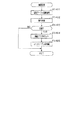
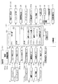
次に、第2判定処理(図20)におけるステップS1205の投入タイミング監視処理について説明する。   Next, the input timing monitoring process in step S1205 in the second determination process (FIG. 20) will be described.

詳細な説明に先立って概略を説明する。スロットマシン10では、上記のように各投入メダル検出センサ86a,86bに対してメダルを往復動させる不正行為だけでなく以下の不正行為が想定される。具体的には、例えば、2個連設された投入メダル検出センサ86a,86bの間隔に対応させて2つの発光体をフィルムなどに埋設させた不正用冶具を用いるものが考えられる。この場合、各発光体が各投入メダル検出センサ86a,86bの検出部にくるようにフィルムを挿入し、各投入メダル検出センサ86a,86bの正規の検出順序に対応させて各発光体を点滅させることでメダルの投入を誤検出させるものと考えられる。これに対して、本スロットマシン10では、メダルの投入タイミングを測定することで異常の有無を判定し、異常有りと判定した場合には異常処理を実行する。   Prior to detailed description, an outline will be described. In the slot machine 10, not only the illegal act of reciprocating medals with respect to the inserted medal detection sensors 86a and 86b as described above but also the following illegal acts are assumed. Specifically, for example, it is possible to use a fraudulent jig in which two light emitters are embedded in a film or the like in correspondence with the interval between two inserted medal detection sensors 86a and 86b. In this case, a film is inserted so that each light emitter comes to the detection part of each inserted medal detection sensor 86a, 86b, and each light emitter is blinked in accordance with the normal detection order of each inserted medal detection sensor 86a, 86b. Therefore, it is considered that the insertion of medals is erroneously detected. On the other hand, in the slot machine 10, the presence / absence of an abnormality is determined by measuring the insertion timing of medals, and if it is determined that there is an abnormality, an abnormality process is executed.

また、投入タイミング監視処理は上記のとおり、第2判定処理において第2通過フラグを格納した後に実行される。つまり、下流側の投入メダル検出センサ86bがON状態となることで(メダルを検出した旨の検出結果となることで)、投入タイミング監視処理が実行される。   Further, as described above, the insertion timing monitoring process is executed after the second passage flag is stored in the second determination process. In other words, the insertion timing monitoring process is executed when the inserted medal detection sensor 86b on the downstream side is turned on (by the detection result indicating that a medal has been detected).

さて、投入タイミング監視処理では、先ずステップS1301にてRAM153の監視タイマカウンタ153cが「0」か否かを判定する。監視タイマカウンタ153cが「0」の場合には、ステップS1302に進み、RAM153のエラーカウンタ153dに基準回数をセットする。この基準回数は、「最大ベット枚数(最大賭け数)―1」の値となっており、具体的にはエラーカウンタ153dに「2」をセットする。続くステップS1303では、監視タイマカウンタ153cに基準間隔(基準期間)をセットする。具体的には、「30」をセットする。その後、本投入タイミング監視処理を終了する。   In the insertion timing monitoring process, first, in step S1301, it is determined whether or not the monitoring timer counter 153c of the RAM 153 is “0”. If the monitoring timer counter 153c is “0”, the process proceeds to step S1302, and the reference count is set in the error counter 153d of the RAM 153. The reference number of times is a value of “maximum bet number (maximum bet number) −1”, and specifically, “2” is set in the error counter 153d. In the subsequent step S1303, a reference interval (reference period) is set in the monitoring timer counter 153c. Specifically, “30” is set. Thereafter, the main input timing monitoring process is terminated.

ここで、上述したように監視タイマカウンタ153cにセットされた値は、投入監視処理(図18)のステップS1001が実行される毎に1減算される。また、投入監視処理は投入メダル検出処理(図17)の一部の処理として実行され、さらに投入メダル検出処理はタイマ割込み処理(図10)の一部の処理として実行される。そして、タイマ割込み処理は、1.49msec周期で起動される。したがって、監視タイマカウンタ153cにセットされたカウント値「30」は、30×1.49msec≒45msecの時間に相当している。   Here, the value set in the monitoring timer counter 153c as described above is decremented by 1 every time step S1001 of the input monitoring process (FIG. 18) is executed. The insertion monitoring process is executed as a part of the inserted medal detection process (FIG. 17), and the inserted medal detection process is executed as a part of the timer interrupt process (FIG. 10). The timer interrupt process is started at a cycle of 1.49 msec. Therefore, the count value “30” set in the monitoring timer counter 153c corresponds to a time of 30 × 1.49 msec≈45 msec.

この45msecという時間は、未使用のセレクタ83に対して未使用の25φのメダルを複数枚連続投入した場合において、下流側の投入メダル検出センサ86bにおけるメダルの検出間隔(検出期間)の実測値よりも小さい値として設定されている。すなわち、基準間隔は、受入部を構成するセレクタ83及び遊技媒体としてのメダルの各形態に基づいて特定される最短検出間隔未満となっている。したがって、正規のメダルの投入においては、下流側の投入メダル検出センサ86bにおける検出間隔は45msecを超え、監視タイマカウンタ153cが「0」となった状況で投入タイミング監視処理が開始され、ステップS1301では上記のとおり肯定判定をする。これに対して、発光体をフィルムなどに埋設させた不正用治具を用いた不正行為が行われる場合、下流側の投入メダル検出センサ86bでの検出間隔は45msec未満となる。したがって、不正行為においては、監視タイマカウンタ153cが「0」となっていない状況で投入タイミング監視処理が開始され、ステップS1301では否定判定をする。   This time of 45 msec is based on an actual measurement value of a medal detection interval (detection period) in the inserted medal detection sensor 86b on the downstream side when a plurality of unused 25φ medals are continuously inserted into the unused selector 83. Is also set as a small value. That is, the reference interval is less than the shortest detection interval specified on the basis of each form of the selector 83 constituting the receiving unit and the medal as the game medium. Accordingly, when a regular medal is inserted, the insertion timing monitoring process is started in a situation where the detection interval of the downstream inserted medal detection sensor 86b exceeds 45 msec and the monitoring timer counter 153c is “0”. In step S1301 Make a positive determination as above. On the other hand, when a fraudulent act using a fraudulent jig in which a light emitter is embedded in a film or the like is performed, the detection interval of the inserted medal detection sensor 86b on the downstream side is less than 45 msec. Therefore, in the case of fraud, the insertion timing monitoring process is started in a situation where the monitoring timer counter 153c is not “0”, and a negative determination is made in step S1301.

ステップS1301にて否定判定をした場合、ステップS1304に進む。ステップS1304では、エラーカウンタ減算処理を実行する。具体的には、RAM153のエラーカウンタ153dの値を1減算する。続くステップS1305では、エラーカウンタ153dの値が「0」か否かを判定する。   If a negative determination is made in step S1301, the process proceeds to step S1304. In step S1304, error counter subtraction processing is executed. Specifically, 1 is subtracted from the value of the error counter 153d in the RAM 153. In a succeeding step S1305, it is determined whether or not the value of the error counter 153d is “0”.

エラーカウンタ153dが「0」でない場合には、ステップS1303にて監視タイマカウンタ153cに「30」をセットした後に本投入タイミング監視処理を終了する。エラーカウンタ153dが「0」である場合には、ステップS1306及びステップS1307の異常処理を実行する。   If the error counter 153d is not “0”, “30” is set in the monitoring timer counter 153c in step S1303, and then the main input timing monitoring process is terminated. If the error counter 153d is “0”, the abnormality processing in steps S1306 and S1307 is executed.

すなわち、ステップS1306では、遊技禁止設定処理を実行する。遊技禁止設定処理では、先ず割込み処理を禁止し、さらに入出力ポート内の全ての出力ポートをクリアすることにより、入出力ポートに接続された全てのアクチュエータをオフ状態に制御して遊技が不可能な状態とする。また、遊技禁止設定処理では異常報知処理を実行する。異常報知処理は上述したとおりである。続くステップS1307では、リセットスイッチ123が操作されるまで待機する。このように異常処理を実行することで、発光体をフィルムなどに埋設させた不正用治具を用いた不正行為が抑制される。   That is, in step S1306, game prohibition setting processing is executed. In the game prohibition setting process, interrupt processing is first prohibited, and all output ports in the input / output port are cleared, so that all actuators connected to the input / output port are controlled to be in an off state, and gaming is impossible. State. In the game prohibition setting process, an abnormality notification process is executed. The abnormality notification process is as described above. In the subsequent step S1307, the process waits until the reset switch 123 is operated. By executing the abnormal process in this way, the illegal act using the fraud jig in which the light emitter is embedded in the film or the like is suppressed.

その後、リセットスイッチ123が操作されることにより、ステップS1307にて肯定判定をし、ステップS1308に進む。ステップS1308では、上述した異常処理を解除する。具体的には、次回のタイマ割込み処理を許可する。また、異常報知処理を解除する。また、ステップS1308では、監視タイマカウンタ153cに「0」をセットするとともに、エラーカウンタ153dに「2」をセットする。その後、本投入タイミング監視処理を終了する。   Thereafter, when the reset switch 123 is operated, an affirmative determination is made in step S1307, and the process proceeds to step S1308. In step S1308, the abnormality process described above is canceled. Specifically, the next timer interrupt process is permitted. Also, the abnormality notification process is canceled. In step S1308, “0” is set to the monitoring timer counter 153c, and “2” is set to the error counter 153d. Thereafter, the main input timing monitoring process is terminated.

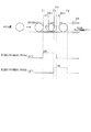
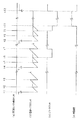
次に、上述した投入タイミング監視処理が実行されることに基づく、異常判定の態様について図23のタイミングチャートに基づき説明する。なお、図23において(a)の第2投入メダル検出センサ86bのタイミングチャートは、当該センサ86bがON状態となったタイミングを表す。   Next, an abnormality determination mode based on the execution of the above-described insertion timing monitoring process will be described based on the timing chart of FIG. In FIG. 23, the timing chart of the second inserted medal detection sensor 86b in (a) represents the timing when the sensor 86b is turned on.

先ず、第1のパターンについて説明する。t1のタイミングで第2投入メダル検出センサ86bがON状態となることにより、監視タイマカウンタ153cに基準間隔(具体的には、「30」)がセットされ、間隔の計測が開始される。また、このタイミングにおいて、エラーカウンタ153dに既に基準回数(具体的には「2」)がセットされていたとしても、基準回数が再度セットされる。その後、t2のタイミングで監視タイマカウンタ153cの値が「0」となり(基準間隔が経過し)、t3のタイミングで第2投入メダル検出センサ86bが再びON状態となる。そして、上記のように監視タイマカウンタ153cの値が「0」の場合に第2投入メダル検出センサ86bがON状態となる状況が継続し、異常処理が実行されることなく遊技が進行していく。当該第1のパターンは上記不正行為が行われない場合の典型的な例である。   First, the first pattern will be described. When the second inserted medal detection sensor 86b is turned on at the timing t1, a reference interval (specifically “30”) is set in the monitoring timer counter 153c, and measurement of the interval is started. Further, at this timing, even if the reference number (specifically “2”) has already been set in the error counter 153d, the reference number is set again. Thereafter, the value of the monitoring timer counter 153c becomes “0” at the timing t2 (the reference interval elapses), and the second inserted medal detection sensor 86b is turned on again at the timing t3. Then, as described above, when the value of the monitoring timer counter 153c is “0”, the situation where the second inserted medal detection sensor 86b is in the ON state continues, and the game proceeds without executing the abnormality process. . The said 1st pattern is a typical example in case the said fraud is not performed.

次に、第2パターンについて説明する。t4のタイミングで第2投入メダル検出センサ86bがON状態となることにより、監視タイマカウンタ153cに基準間隔がセットされ、間隔の計測が開始される。また、このタイミングにおいて、エラーカウンタ153dに既に基準回数がセットされていたとしても、基準回数が再度セットされる。その後、監視タイマカウンタ153cが「0」となる前であるt5のタイミングで第2投入メダル検出センサ86bが再びON状態となる。かかる場合、第2投入メダル検出センサ86bにおける検出間隔が基準間隔を下回ったこととなり、エラーカウンタ153dの値が1減算される。   Next, the second pattern will be described. When the second inserted medal detection sensor 86b is turned on at timing t4, the reference interval is set in the monitoring timer counter 153c, and the measurement of the interval is started. At this timing, even if the reference number is already set in the error counter 153d, the reference number is set again. Thereafter, the second inserted medal detection sensor 86b is turned on again at the timing t5 before the monitoring timer counter 153c becomes “0”. In this case, the detection interval in the second inserted medal detection sensor 86b is less than the reference interval, and the value of the error counter 153d is decremented by 1.

その後、t6のタイミングで監視タイマカウンタ153cの値が「0」となり、t7のタイミングで第2投入メダル検出センサ86bが再びON状態となる。かかる場合、第2投入メダル検出センサ86bにおける検出間隔が基準間隔を超えているため、エラーカウンタ153dに基準回数が再びセットされる。当該第2のパターンは、複数枚のメダルが連続投入された際にその投入された各メダルの挙動が乱れ、上記検出間隔が基準間隔を偶然下回った場合に起こり得る。   Thereafter, the value of the monitoring timer counter 153c becomes “0” at the timing of t6, and the second inserted medal detection sensor 86b is turned on again at the timing of t7. In this case, since the detection interval in the second inserted medal detection sensor 86b exceeds the reference interval, the reference count is set again in the error counter 153d. The second pattern may occur when the behavior of each inserted medal is disturbed when a plurality of medals are continuously inserted and the detection interval falls below the reference interval by chance.

次に、第3のパターンについて説明する。t8のタイミングで第2投入メダル検出センサ86bがON状態となることにより、監視タイマカウンタ153cに基準間隔がセットされ、間隔の計測が開始される。また、このタイミングにおいて、エラーカウンタ153dに既に基準回数がセットされていたとしても、基準回数が再度セットされる。その後、t9のタイミング及びt10のタイミングのそれぞれにおいて、監視タイマカウンタ153cが「0」となる前に第2投入メダル検出センサ86bが再びON状態となり、エラーカウンタ153dの値がそれぞれ1減算される。これにより、t10のタイミングでエラーカウンタ153dの値が「0」となり、異常処理として異常報知処理及び遊技禁止処理が開始される。これら各処理が実行されることにより、上記不正用冶具を用いてメダルの投入を誤検出させようとする不正行為がさらに続けて行われることを抑制することができる。   Next, the third pattern will be described. When the second inserted medal detection sensor 86b is turned on at timing t8, the reference interval is set in the monitoring timer counter 153c, and the measurement of the interval is started. At this timing, even if the reference number is already set in the error counter 153d, the reference number is set again. Thereafter, at each of timings t9 and t10, the second inserted medal detection sensor 86b is turned on again before the monitoring timer counter 153c becomes “0”, and the value of the error counter 153d is decremented by one. Thereby, the value of the error counter 153d becomes “0” at the timing of t10, and the abnormality notification process and the game prohibition process are started as the abnormality process. By executing each of these processes, it is possible to suppress further illegal acts that are intended to erroneously detect the insertion of medals using the fraudulent jig.

特に、エラーカウンタ153dにセットされる基準回数は「2」であるため、上記不正用冶具を用いてメダルの投入を誤検出させようとする不正行為が行われた場合には、メダルのベット枚数が最大ベット枚数となったタイミングで異常処理が実行される。そして、当該異常処理が実行されると、その後の遊技が禁止される。したがって、上記不正行為が行われ続けることを抑制できるだけでなく、最大ベット枚数による遊技が1度でも実行されてしまうことを抑制できる。その後、t11のタイミングでリセットスイッチ123が操作されることにより、異常報知が解除されるとともに、遊技禁止処理が解除される。   In particular, since the reference number set in the error counter 153d is “2”, the bet number of medals is determined when an illegal act is attempted to erroneously detect the insertion of medals using the fraudulent jig. Abnormal processing is executed at the timing when becomes the maximum bet number. When the abnormality process is executed, subsequent games are prohibited. Therefore, it is possible not only to prevent the illegal act from being continued, but also to prevent the game with the maximum bet number from being executed even once. Thereafter, when the reset switch 123 is operated at the timing of t11, the abnormality notification is released and the game prohibition process is released.

投入メダル検出処理の説明に戻り、ステップS901にて投入監視処理を実行した後は、ステップS902にて正常なメダルの検出があったか否かを判定する。かかる判定は、通過完了フラグが格納されているか否かを判定することにより行われる(通過完了フラグは投入監視処理(図18)におけるステップS1008にて格納される)。   Returning to the explanation of the inserted medal detection process, after the insertion monitoring process is executed in step S901, it is determined in step S902 whether a normal medal is detected. This determination is made by determining whether or not a passage completion flag is stored (the passage completion flag is stored in step S1008 in the input monitoring process (FIG. 18)).

正常なメダルの検出がなかった場合には、そのまま本投入メダル検出処理を終了する。正常なメダルの検出があった場合には、ステップS903に進む。なお、この際、通過完了フラグをクリアする。ステップS903では、RAM153のベットメダル記憶エリア153bを確認することにより、最大ベット枚数となっているか否かを判定する。この最大ベット枚数は、例えば、遊技状態が通常ゲームの場合には「3」となっている。最大ベット枚数でない場合には、ステップS904にてRAM153のベットメダル記憶エリア153bの値(ベット枚数)を1加算した後に、ステップS906に進む。一方、最大ベット枚数である場合には、ステップS905にて仮想メダル枚数を1加算した後にステップS906に進む。つまり、最大ベット枚数の状況においてメダルが投入されると、その投入されたメダルは仮想メダルとして貯留記憶される。   If no normal medal is detected, the inserted medal detection process is terminated. If a normal medal is detected, the process proceeds to step S903. At this time, the passage completion flag is cleared. In step S903, the bet medal storage area 153b in the RAM 153 is checked to determine whether or not the maximum bet number has been reached. This maximum bet number is, for example, “3” when the game state is a normal game. If it is not the maximum bet number, the value (bet number) in the bet medal storage area 153b of the RAM 153 is incremented by 1 in step S904, and the process proceeds to step S906. On the other hand, if it is the maximum bet number, the virtual medal number is incremented by 1 in step S905, and the process proceeds to step S906. That is, when a medal is inserted in the maximum bet number situation, the inserted medal is stored and stored as a virtual medal.

ステップS906では、最大ベット枚数であって最大仮想メダル枚数(例えば、50枚)であるか否かを判定する。いずれかが最大枚数でない場合には、そのまま本投入メダル検出処理を終了する。いずれも最大枚数である場合には、ステップS907にてメダル通路切替ソレノイド83aを非励磁状態としてメダルの投入を不許可とした後に、本投入メダル検出処理を終了する。このメダルの投入を不許可とした状態は、最大ベット枚数の状態又は最大仮想メダル枚数の状態のいずれかが解消されることに応じて、解除される。   In step S906, it is determined whether or not the maximum bet number is the maximum virtual medal number (for example, 50). If any of them is not the maximum number, the present inserted medal detection process is terminated as it is. If both are the maximum number, the medal path switching solenoid 83a is de-energized in step S907 to prohibit the medal insertion, and then the inserted medal detection process is terminated. This state where the insertion of medals is not permitted is canceled in response to the cancellation of either the maximum bet number state or the maximum virtual medal number state.

通常処理の説明に戻り、メダルがベットされているときには、続いてステップS503にて有効ライン設定処理を実行する。有効ライン設定処理では、RAM153のベットメダル記憶エリア153bを確認することにより、現在のベット枚数を把握し、その把握したベット枚数に応じて有効ラインを設定する。このベット枚数に応じた有効ラインの設定については既に説明したとおりであるので、ここでは説明を省略する。ちなみに、設定された有効ライン数が多いほど、後述する抽選処理にて当選となった役の入賞が成立し易くなる。つまり、設定された有効ライン数が多いほど、すなわちベット枚数が多いほど、1遊技回でのメダルの獲得期待値が高くなると言える。   Returning to the description of the normal process, when a medal is bet, an active line setting process is subsequently executed in step S503. In the effective line setting process, the bet medal storage area 153b of the RAM 153 is checked to grasp the current bet number, and an effective line is set according to the grasped bet number. Since the setting of the effective line according to the number of bets has already been described, the description thereof is omitted here. Incidentally, the greater the number of set effective lines, the easier it is to win a winning combination in a lottery process to be described later. In other words, it can be said that as the number of set effective lines increases, that is, as the number of bets increases, the expected medal acquisition value in one game round increases.

続くステップS504では、スタートレバー71が操作されたか否かを判定する。ステップS502,ステップS504が共にYESの場合には、ステップS505にてベット不許可処理を実行する。具体的には、RAM153の遊技中フラグ格納エリアに遊技中フラグをセットする。当該遊技中フラグがセットされることにより、クレジット投入検出センサ77a〜79aからのON信号が無効化される。また、メダル通路切替ソレノイド83aが非励磁とされ、仮にメダル投入口75からメダルが投入されたとしても皿用通路82を介して遊技者にかかるメダルが返却されるようになる。さらには、精算検出センサ80aからのON信号が無効化される。   In a succeeding step S504, it is determined whether or not the start lever 71 is operated. If both step S502 and step S504 are YES, bet non-permission processing is executed in step S505. Specifically, a gaming flag is set in the gaming flag storage area of the RAM 153. By setting the game-in-progress flag, the ON signals from the credit insertion detection sensors 77a to 79a are invalidated. Further, the medal passage switching solenoid 83a is de-energized, and even if a medal is inserted from the medal insertion slot 75, the medal for the player is returned via the tray passage 82. Furthermore, the ON signal from the settlement detection sensor 80a is invalidated.

その後、ステップS506の抽選処理、ステップS507のリール制御処理、ステップS508のメダル払出処理、ステップS509のBBゲーム処理を順に実行し、ステップS510ではベット許可処理を行う。かかる処理では、RAM153の遊技中フラグ格納エリアから遊技中フラグをクリアする。これにより、クレジット投入検出センサ77a〜79a及び精算検出センサ80aからのON信号の無効化状態が解除される。また、メダル通路切替ソレノイド83aが励磁され、メダル投入口75からメダルが投入された際にホッパ用通路81へ導かれるようになる。以上の処理を行った後、ステップS501に戻る。一方、ステップS502にてメダルがベットされていない、またはステップS504にてスタートレバー71が操作されていない場合には、ステップS501に戻る。   Thereafter, a lottery process in step S506, a reel control process in step S507, a medal payout process in step S508, and a BB game process in step S509 are executed in this order, and a bet permission process is performed in step S510. In this process, the in-game flag is cleared from the in-game flag storage area of the RAM 153. Thereby, the invalid state of the ON signal from the credit insertion detection sensors 77a to 79a and the payment detection sensor 80a is canceled. Further, when the medal passage switching solenoid 83a is excited and a medal is inserted from the medal insertion port 75, the medal passage switching solenoid 83a is guided to the hopper passage 81. After performing the above process, it returns to step S501. On the other hand, if no medal is bet in step S502 or the start lever 71 is not operated in step S504, the process returns to step S501.

次に、通常処理におけるステップS506〜ステップS508の各処理について説明する。なお、ステップS509のBBゲーム処理は、BBゲームの開始、BBゲームの進行、及びBBゲームの終了に関する制御を行う処理であり、ここでは詳細な説明を省略する。   Next, each process of step S506 to step S508 in the normal process will be described. Note that the BB game process in step S509 is a process for controlling the start of the BB game, the progress of the BB game, and the end of the BB game, and detailed description thereof is omitted here.

ステップS506の抽選処理について、図24のフローチャートに基づき説明する。   The lottery process in step S506 will be described based on the flowchart in FIG.

ステップS1401では、乱数テーブル選択処理を実行する。当該乱数テーブル選択処理では、スロットマシン10の現在の設定状態に基づき、当否決定用の乱数テーブルを選択する。ここで、スロットマシン10の設定状態は図示しない設定キーを用いてセットされた「設定1」〜「設定6」のいずれかであり、「設定1」のときに役の当選確率が最も低い乱数テーブルが選択され、「設定6」のときに役の当選確率が最も高い乱数テーブルが選択される。   In step S1401, random number table selection processing is executed. In the random number table selection process, a random number table for determining success / failure is selected based on the current setting state of the slot machine 10. Here, the setting state of the slot machine 10 is any one of “setting 1” to “setting 6” set using a setting key (not shown), and the random number having the lowest winning probability of the combination when “setting 1” is set. A table is selected, and when “setting 6” is selected, the random number table having the highest winning probability of the combination is selected.

また、乱数テーブル選択処理では、現在のベット枚数に基づき、当否決定用の乱数テーブルを選択する。つまり、乱数テーブル選択処理では、RAM153のベットメダル記憶エリア153bを確認し、当該エリア153bに格納された値に基づいて当否決定用の乱数テーブルを選択する。具体的には、ベット枚数は1〜3枚のいずれかであり、ベット枚数が多いほど役の当選確率が高くなるような乱数テーブルが選択される。例えば3枚ベットされたときの役の当選確率は、1枚ベットされたときの役の当選確率と比して3倍よりも高い確率となっている。かかる構成より、ベット枚数が多いほど、1遊技回でのメダルの獲得期待値が高くなると言える。   Further, in the random number table selection process, a random number table for determination of success / failure is selected based on the current bet number. That is, in the random number table selection process, the bet medal storage area 153b of the RAM 153 is confirmed, and a random number table for determination of success / failure is selected based on the value stored in the area 153b. Specifically, the bet number is any one of 1 to 3, and a random number table is selected such that the greater the bet number, the higher the winning probability of the winning combination. For example, the winning probability of a winning combination when three bets are higher than the winning probability of winning when a single bet is three times. From this configuration, it can be said that as the number of bets increases, the expected acquisition value of medals in one game round increases.

ステップS1402では、このようにして選択された乱数テーブルに、スタートレバー71が操作されたときに乱数カウンタ154よりラッチした乱数を照らして役の抽選を行う。そしてステップS1403にていずれかの役に当選したか否かを判定し、いずれの役にも当選していない場合にはそのまま本処理を終了する。いずれかの役に当選した場合にはステップS1404に進み、その役に応じた当選フラグをセットすると共に図柄を揃えるべき有効ラインを決定する。続いてステップS1405ではリール停止制御用のスベリテーブルを決定し、これをRAM153のスベリテーブル格納エリアに格納する。ここで、スベリテーブルとは、ストップスイッチ72〜74が押されたタイミングにおける所定の有効ライン上の図柄と、その有効ライン上に停止させるべき図柄とが異なる場合に、その停止させるべき図柄を所定の有効ライン上で止まるようにリールをどれだけ滑らせるかを定めたテーブルである。   In step S1402, the lottery of the winning combination is performed by comparing the random number table selected in this way with the random number latched by the random number counter 154 when the start lever 71 is operated. In step S1403, it is determined whether or not any combination has been won. If any combination has not been won, the process is terminated. If any of the winning combinations is won, the process proceeds to step S1404, and a winning flag corresponding to the winning combination is set and an effective line to be aligned is determined. In step S1405, a reel table for reel stop control is determined and stored in the slip table storage area of the RAM 153. Here, when the symbols on the predetermined effective line at the timing when the stop switches 72 to 74 are pressed are different from the symbols to be stopped on the effective line, the slip table is a predetermined symbol to be stopped. It is a table that defines how much the reel slides so as to stop on the active line.

次に、ステップS507のリール制御処理について、図25のフローチャートに基づき説明する。   Next, the reel control processing in step S507 will be described based on the flowchart of FIG.

リール制御処理では、先ずステップS1501においてウエイト処理を行う。このウエイト処理は、前回のゲームにおいてリールの回転を開始した時点から所定時間(例えば4.1秒)が経過するまで今回のゲームにおいてリールの回転を開始せずに待機する処理である。このため、遊技者がメダルをベットしてスタートレバー71を操作したとしても、直ちに各リール42L,42M,42Rが回転しないことがある。ウエイト処理に続いてステップS1502のリール回転処理を行い、各リール42L,42M,42Rを回転させる。その後、ステップS1503に進み、左リール42Lが回転を開始してから所定時間が経過したか否かを判定し、経過していない場合には所定時間が経過するまで待機する。所定時間が経過した場合にはステップS1504に進み、ストップスイッチ72〜74のいずれかが押下操作されてリールの停止指令が発生したか否か、より具体的にはストップ検出センサ72a〜74aからのON信号を受信しているか否かを判定する。停止指令が発生していない場合にはステップS1505に進み、予め定められた各リール42L,42M,42Rの最大回転時間を経過したか否かを判定する。最大回転時間を経過していない場合にはステップS1504に戻り、最大回転時間を経過した場合にはステップS1506に進んで回転中の全てのリールを強制的に順次停止させる強制停止処理を行う。   In the reel control process, first, a wait process is performed in step S1501. This wait process is a process of waiting without starting the reel rotation in the current game until a predetermined time (for example, 4.1 seconds) elapses from the time when the reel rotation is started in the previous game. Therefore, even if the player bets a medal and operates the start lever 71, the reels 42L, 42M, and 42R may not immediately rotate. Following the wait process, the reel rotation process in step S1502 is performed to rotate the reels 42L, 42M, and 42R. Thereafter, the process proceeds to step S1503, where it is determined whether or not a predetermined time has elapsed since the left reel 42L started rotating. If not, the process waits until the predetermined time elapses. If the predetermined time has elapsed, the process proceeds to step S1504, where one of the stop switches 72 to 74 is pressed to generate a reel stop command, more specifically, from the stop detection sensors 72a to 74a. It is determined whether an ON signal is received. If no stop command has been issued, the process advances to step S1505 to determine whether or not a predetermined maximum rotation time of each of the reels 42L, 42M, and 42R has elapsed. If the maximum rotation time has not elapsed, the process returns to step S1504. If the maximum rotation time has elapsed, the process proceeds to step S1506 to perform a forced stop process for forcibly and sequentially stopping all the rotating reels.

一方、ステップS1504にてストップスイッチ72〜74のいずれかが押下操作されて停止指令が発生した場合には、ステップS1507に進み、リール停止処理を行う。このリール停止処理では、押下操作されたストップスイッチに対応するリールを停止させるが、役の抽選において役に当選し、当選フラグがセットされている場合にはRAM153のスベリテーブル格納エリアに格納されたスベリテーブルを参照して、可能な限り当選した役が所定の有効ライン上に並ぶように制御する。   On the other hand, if any of the stop switches 72 to 74 is pressed down in step S1504 to generate a stop command, the process proceeds to step S1507, and reel stop processing is performed. In this reel stop process, the reel corresponding to the pressed stop switch is stopped. If a winning combination is won in the winning lottery and the winning flag is set, the reel is stored in the sliding table storage area of the RAM 153. With reference to the sliding table, control is performed so that the winning combinations are arranged on a predetermined effective line as much as possible.

続いて、ステップS1508では今回の停止指令が第1停止指令か否か、すなわち3つのリール全てが回転しているときにストップスイッチが押下操作されたか否かを判定する。第1停止指令の場合には、ステップS1509に進み、スベリテーブル変更処理を行う。このスベリテーブル変更処理では、例えば当選した有効ライン上で役を揃えようとしたときに役の複合が発生するか否かを判定し、役の複合が発生しないときにはそのまま次のステップに移行し、役の複合が発生するときには当選した有効ラインを別の有効ラインに変更すると共に変更後の有効ラインに合ったスベリテーブルに変更した後に次のステップに移行する。   In step S1508, it is determined whether or not the current stop command is the first stop command, that is, whether or not the stop switch has been pressed when all three reels are rotating. In the case of the first stop command, the process proceeds to step S1509, and a slip table changing process is performed. In this slide table change process, for example, it is determined whether or not a combination of combinations occurs when trying to align a combination on the selected active line, and when a combination of combinations does not occur, the process proceeds to the next step as it is. When a combination of combinations occurs, the selected effective line is changed to another effective line, and after changing to a sliding table suitable for the changed effective line, the process proceeds to the next step.

一方、ステップS1508で今回の停止指令が第1停止指令でないときには、ステップS1510に進み、第2停止指令か否か、つまり3つのリールのうち1つのリールが停止し2つのリールが回転しているときにストップスイッチが押下操作されたか否かを判定する。第2停止指令のときにはステップS1511に進み、停止目判定処理を行う。この停止目判定処理では、2つのリールが停止したときにその2つが「7」図柄等のボーナス図柄で揃っているか否かを判定し、揃っていないときにはそのまま次のステップに移行し、揃っているときにはスピーカ14から効果音等を発生させた後に次のステップに移行する。   On the other hand, if the current stop command is not the first stop command in step S1508, the process proceeds to step S1510 to determine whether the second stop command is present, that is, one of the three reels is stopped and the two reels are rotating. It is determined whether or not the stop switch has been pressed. If it is the second stop command, the process proceeds to step S1511 to perform stop eye determination processing. In this stop eye determination process, when two reels are stopped, it is determined whether or not the two are aligned with a bonus symbol such as “7” symbol. If they are not aligned, the process proceeds to the next step as it is. When sound effects are generated from the speaker 14, the process proceeds to the next step.

そして、ステップS1506の強制停止処理の後、ステップS1509のスベリテーブル変更処理の後、ステップS1510にて今回の停止指令が第2停止指令でなかったとき、又はステップS1511の停止目判定処理を行った後には、ステップS1512にて左、中、右リール42L,42M,42Rのすべての回転が停止したか否かを判定する。ステップS1512がNOの場合にはステップS1504に戻り、YESの場合には続くステップS1513にて払出判定処理を行った後に本リール制御処理を終了する。   Then, after the forced stop process in step S1506, after the slip table change process in step S1509, when the current stop command is not the second stop command in step S1510, or the stop eye determination process in step S1511 is performed. Thereafter, in step S1512, it is determined whether or not all rotations of the left, middle, and right reels 42L, 42M, and 42R have stopped. If NO in step S1512, the process returns to step S1504. If YES, the payout determination process is performed in subsequent step S1513, and then the reel control process is terminated.

払出判定処理では、役が有効ライン上に並んでいるか否かを判定し、役が有効ライン上に並んでいないときにはRAM153の払出予定数格納エリアに「0」をセットし、役が有効ライン上に並んでいるときにはその役が当選した役と一致しているか否かを判定し、一致していないときには上部ランプ13等によりエラー表示を行うと共に払出予定数格納エリアに「0」をセットする。一致しているときには払出予定数格納エリアに並んだ役と対応する払出数をセットする。   In the payout determination process, it is determined whether or not the winning combination is on the active line. If the winning combination is not aligned on the effective line, “0” is set in the payout number storage area of the RAM 153, and the winning combination is on the effective line. If they are aligned, it is determined whether or not the winning combination matches the winning combination. If they do not match, an error is displayed by the upper lamp 13 or the like and “0” is set in the payout number storage area. If they match, the number of payouts corresponding to the combinations arranged in the payout amount storage area is set.

次に、ステップS508のメダル払出処理について、図26のフローチャートに基づき説明する。   Next, the medal payout process in step S508 will be described based on the flowchart of FIG.

メダル払出処理では、先ずステップS1601にて払出数カウンタがカウントした払出数と、払出予定数格納エリアに格納された払出予定数とが一致しているか否かを判定する。払出数と払出予定数とが一致していないときには、ステップS1602にてRAM153の仮想メダル記憶エリア153aの仮想メダル枚数が上限(貯留されている仮想メダル枚数が50枚)に達しているか否かを判定する。上限に達していないときには、ステップS1603,S1605にて仮想メダル記憶エリア153aの仮想メダル枚数及び払出数をそれぞれ1加算する。その後、ステップS1606では、クレジット表示部35及び獲得枚数表示部36の枚数をそれぞれ1加算するための表示部変更処理を行う。   In the medal payout process, first, it is determined whether or not the payout number counted by the payout number counter in step S1601 matches the payout planned number stored in the payout planned number storage area. If the number of payouts does not match the number of payouts, it is determined in step S1602 whether or not the number of virtual medals in the virtual medal storage area 153a of the RAM 153 has reached the upper limit (the number of stored virtual medals is 50). judge. If the upper limit has not been reached, 1 is added to each of the number of virtual medals and the number of payouts in the virtual medal storage area 153a in steps S1603 and S1605. Thereafter, in step S1606, display unit change processing is performed to add 1 to the number of credit display unit 35 and acquired number display unit 36, respectively.

一方、ステップS1602にて仮想メダル記憶エリア153aの仮想メダル枚数が上限に達しているときには、ステップS1604にてメダル払出用回転板を駆動してメダルをホッパ装置91からメダル排出口17を介してメダル受け皿18へ払い出す。続くステップS1605ではホッパ装置91に取り付けられた払出検出センサ91aのメダル検出信号に応じて払出数を1加算する。その後、ステップS1606にて獲得枚数表示部36の枚数を1加算するための表示部変更処理を行う。ステップS1606にて表示部変更処理を行った後、再びステップS1601に戻る。ステップS1601で払出数と払出予定数とが一致したときには、ステップS1607にて払出終了処理を行った後に本メダル払出処理を終了する。払出終了処理では、払出予定数格納エリアや払出数カウンタの値を「0」にクリアする。   On the other hand, if the number of virtual medals in the virtual medal storage area 153a has reached the upper limit in step S1602, the medal payout rotary plate is driven in step S1604 and the medal is received from the hopper device 91 through the medal discharge port 17. Pay out to the saucer 18. In subsequent step S1605, 1 is added to the number of payouts according to the medal detection signal of the payout detection sensor 91a attached to the hopper device 91. After that, in step S1606, display part change processing for adding 1 to the number of acquired number display part 36 is performed. After performing a display part change process in step S1606, it returns to step S1601 again. If the number of payouts matches the planned number of payouts in step S1601, the payout end process is performed in step S1607, and then the medal payout process ends. In the payout end process, the payout amount storage area and the payout counter value are cleared to “0”.

以上詳述した本実施の形態によれば、以下の優れた効果を奏する。   According to the embodiment described in detail above, the following excellent effects are obtained.

主制御装置131のRAM153に監視タイマカウンタ153cを設け、投入メダル検出センサ86a,86bにおけるメダルの検出間隔を把握するようにした。そして、この検出間隔が基準間隔以下となったことに基づいて異常処理を実行するようにした。不正用冶具を用いて投入メダル検出センサ86a,86bにメダルの投入を誤検出させる不正行為が行われる場合、投入メダル検出センサ86a,86bにおける検出間隔は正規のメダルの投入時における検出間隔よりも短くなる。これに対して、上記のとおり、検出間隔が基準間隔以下となったことに基づいて異常処理を実行することで、上記不正行為が行われ続けることを抑制することができる。また、かかる不正行為が行われ続けることが抑制されることにより、仮想メダルの貯留記憶を不正に行わせることに基づいてメダルを取得する不正行為が行われ続けることをも抑制することができる。   A monitoring timer counter 153c is provided in the RAM 153 of the main controller 131 so as to grasp the detection interval of medals in the inserted medal detection sensors 86a and 86b. Then, the abnormality process is executed based on the fact that the detection interval is equal to or less than the reference interval. When an illegal act of erroneously detecting insertion of medals by the inserted medal detection sensors 86a and 86b is performed using a fraudulent jig, the detection interval of the inserted medal detection sensors 86a and 86b is larger than the detection interval at the time of insertion of a regular medal. Shorter. On the other hand, as described above, by executing the abnormality process based on the fact that the detection interval is equal to or less than the reference interval, it is possible to suppress the unauthorized action from being continued. Moreover, it can also be suppressed that the illegal act which acquires a medal based on making storage storage of a virtual medal illegally is suppressed by suppressing that the illegal act is continued.

上記基準間隔を、セレクタ83及びメダルの各形態に基づいて特定される最短検出間隔未満となるよう設定した。これにより、正規のメダルの投入時において投入メダル検出センサ86a,86bにおける検出間隔が基準間隔以下となる可能性が低減され、当該状況において異常処理が実行されてしまうことが抑制される。   The reference interval was set to be less than the shortest detection interval specified based on the selector 83 and each form of the medal. As a result, the possibility that the detection interval of the inserted medal detection sensors 86a and 86b becomes equal to or less than the reference interval when a regular medal is inserted is reduced, and abnormal processing is suppressed from being performed in this situation.

主制御装置131のRAM153にエラーカウンタ153dを設け、投入メダル検出センサ86a,86bにおけるメダルの検出間隔が基準間隔以下となる状況が連続する場合の連続回数を把握し、当該連続回数が予め設定された基準回数に達した場合に異常処理を実行するようにした。これにより、正規のメダルの投入時において異常処理が実行されてしまうことが抑制される。正規のメダルの投入時においては、投入メダル検出センサ86a,86bにおける検出間隔が基準間隔以下となる状況が連続することはないからである。一方、不正用冶具を用いて投入メダル検出センサ86a,86bにメダルの投入を誤検出させる不正行為が行われる場合、検出間隔が基準間隔以下となる状況が連続して発生するため、上記不正行為が行われ続けることを抑制するという効果は確保される。   An error counter 153d is provided in the RAM 153 of the main controller 131, and the number of consecutive times when the situation where the detection interval of medals in the inserted medal detection sensors 86a and 86b is equal to or less than the reference interval continues is determined. The abnormal process is executed when the specified number of times is reached. As a result, the abnormal process is suppressed from being executed when a regular medal is inserted. This is because, when a regular medal is inserted, the situation where the detection interval of the inserted medal detection sensors 86a and 86b is equal to or less than the reference interval does not continue. On the other hand, when an illegal act of erroneously detecting the insertion of a medal is performed by the inserted medal detection sensors 86a and 86b using a fraudulent jig, the situation where the detection interval is equal to or less than the reference interval continuously occurs. Therefore, the effect of suppressing the ongoing operation is ensured.

上記基準回数を、「最大ベット枚数(最大賭け数)−1」の値とした。本スロットマシン10では、最大ベット枚数の範囲内においてベット枚数(賭け数)が多くなるほど、1の遊技回でのメダルの獲得期待値が大きくなる。例えば、ベット枚数が多くなるほど、抽選処理(図24)にて役の当選確率が高いに乱数テーブル(抽選情報群)が選択され、有効ライン設定処理(図13のステップS503)にて多数の有効ラインが設定される。この場合に、基準回数が上記のとおり設定されていることにより、不正用冶具を用いて投入メダル検出センサ86a,86bにメダルの投入を誤検出させる不正行為が行われたとしても、少なくとも最大ベット枚数に達した場合には異常処理が実行される。よって、上記不正行為により最大ベット枚数とした状況で遊技が行われてしまうことを抑制することができる。   The reference number of times was a value of “maximum bet number (maximum bet number) −1”. In the slot machine 10, the expected value for acquiring medals in one game round increases as the bet number (the number of bets) increases within the range of the maximum bet number. For example, as the number of bets increases, the random number table (lottery information group) is selected with a higher winning probability in the lottery process (FIG. 24), and a larger number of valid lines are set in the effective line setting process (step S503 in FIG. 13). A line is set. In this case, since the reference number of times is set as described above, at least the maximum bet can be obtained even if an illegal act of erroneously detecting the insertion of medals by the insertion medals detection sensors 86a and 86b is performed using the fraudulent jig. When the number of sheets is reached, abnormal processing is executed. Therefore, it is possible to prevent a game from being played in a situation where the maximum bet number is set due to the above fraud.

上記検出間隔が異常か否かの判定を行うための投入タイミング監視処理(図22)を、投入メダル検出処理(図17)における投入監視処理にて行うようにした。また、当該投入監視処理は、投入メダル検出処理においてベット枚数を加算する処理や、仮想メダル枚数を加算する処理よりも前に行われる。これにより、上記検出間隔が異常か否かの判定は、ベット枚数を加算する前のタイミングで、又は仮想メダル枚数を加算する前のタイミングで実行される。また、当該タイミングで上記検出間隔が異常か否かの判定が行われることにより、異常有りと判定された場合に異常処理は、ベット枚数を加算する前のタイミングで、又は仮想メダル枚数を加算する前のタイミングで実行される。これにより、異常処理が実行される場合における最終回の不正行為に基づくベット枚数の加算、又は仮想メダルの貯留記憶を阻止することが可能となり、上記不正行為が行われ続けることを抑制できるだけでなく、遊技ホールの被る被害を極力抑えることが可能となる。   The insertion timing monitoring process (FIG. 22) for determining whether or not the detection interval is abnormal is performed in the insertion monitoring process in the insertion medal detection process (FIG. 17). The insertion monitoring process is performed before the process of adding the bet number in the inserted medal detection process and the process of adding the virtual medal number. Thereby, the determination as to whether or not the detection interval is abnormal is executed at a timing before the bet number is added or at a timing before the virtual medal number is added. In addition, when it is determined that there is an abnormality by determining whether or not the detection interval is abnormal at the timing, the abnormality process adds the number of virtual medals at the timing before adding the number of bets. It is executed at the previous timing. As a result, it becomes possible to prevent the addition of the number of bets based on the final fraud in the case of abnormal processing being performed or the storage and storage of virtual medals, and not only to suppress the continued fraud. It is possible to minimize damage to the game hall as much as possible.

投入タイミング監視処理は、ベット許可状態において実行され、ベット不許可状態においては実行されない。すなわち、遊技が開始され当該遊技が継続している状況において投入タイミング監視処理が実行されないようになっている。遊技に関わる制御では、抽選処理(図19)やリール制御処理(図20)が実行され、その制御の処理負荷は比較的大きなものであり、当該遊技に関わる制御に対して投入タイミング監視処理が並行して行われると主制御装置131のCPU151における制御処理負荷が増大してしまうおそれがある。これに対して、上記のとおり投入タイミング監視処理はベット許可状態において実行されるため、遊技に関わる制御に対して投入タイミング監視処理が並行して行われることはなく、上記のような制御処理負荷の増大化が抑制されている。   The insertion timing monitoring process is executed in the bet permission state and is not executed in the bet disapproval state. That is, in the situation where the game is started and the game continues, the insertion timing monitoring process is not executed. In the control related to the game, a lottery process (FIG. 19) and a reel control process (FIG. 20) are executed, and the processing load of the control is relatively large. If performed in parallel, the control processing load on the CPU 151 of the main controller 131 may increase. On the other hand, since the insertion timing monitoring process is executed in the bet permission state as described above, the insertion timing monitoring process is not performed in parallel with the control related to the game. The increase of is suppressed.

(第2の実施形態)
本実施形態では、投入タイミング監視処理及びそれに関連した構成が上記第1の実施形態と異なっている。そこで、以下にかかる相違する構成について説明する。なお、上記第1の実施形態と同一の構成については基本的に説明を省略する。
(Second Embodiment)
In the present embodiment, the input timing monitoring process and the configuration related thereto are different from those in the first embodiment. Therefore, a different configuration according to the following will be described. In addition, description is abbreviate | omitted fundamentally about the structure same as the said 1st Embodiment.

本実施形態では、主制御装置131のRAM153に、上記第1の実施形態における各記憶エリアだけでなく、さらに計測結果記憶エリア153eが設けられている。この計測結果記憶エリア153eにより、第2投入メダル検出センサ86bにおける検出間隔の履歴が記憶される。また、監視タイマカウンタ153cは、上記第1の実施形態では減算式であったが、本実施形態では加算式となっている。つまり、検出間隔の把握に際しては、監視タイマカウンタ153cに先ず「0」がセットされ、その後、タイマ割込み処理が起動される度に1加算され、その加算後の値により検出間隔が把握される。   In the present embodiment, the RAM 153 of the main controller 131 is provided with not only the storage areas in the first embodiment but also a measurement result storage area 153e. The measurement result storage area 153e stores a history of detection intervals in the second inserted medal detection sensor 86b. The monitoring timer counter 153c is a subtraction formula in the first embodiment, but is an addition formula in the present embodiment. That is, when grasping the detection interval, “0” is first set in the monitoring timer counter 153c, and thereafter, 1 is added every time the timer interrupt processing is started, and the detection interval is grasped by the value after the addition.

次に、本実施形態における投入監視処理について図28のフローチャートを用いて説明する。   Next, the input monitoring process in the present embodiment will be described with reference to the flowchart of FIG.

投入監視処理におけるステップS1701では、監視タイマカウンタ153cの値が計測上限値であるか否かを判定する。具体的には、監視タイマカウンタ153cの値が「40000」か否かを判定する。計測上限値でない場合には、ステップS1702にて監視タイマカウンタ加算処理を実行する。具体的には、監視タイマカウンタ153cの値を1加算する。その後、ステップS1703に進む。一方、計測上限値である場合には、ステップS1702の処理を実行することなくステップS1703に進む。   In step S1701 in the input monitoring process, it is determined whether or not the value of the monitoring timer counter 153c is a measurement upper limit value. Specifically, it is determined whether or not the value of the monitoring timer counter 153c is “40000”. If it is not the measurement upper limit value, a monitoring timer counter addition process is executed in step S1702. Specifically, 1 is added to the value of the monitoring timer counter 153c. Thereafter, the process proceeds to step S1703. On the other hand, when it is a measurement upper limit, it progresses to step S1703, without performing the process of step S1702.

つまり、本実施形態では、監視タイマカウンタ153cの値は、計測上限値の範囲内において投入監視処理が実行される度に1加算される。そして、当該投入監視処理はタイマ割込み処理の一部の処理として実行されるため、1.49msec周期で繰り返し実行される。すなわち、監視タイマカウンタ153cの値は、計測上限値の範囲内において1.49msec周期で1加算される。一方、監視タイマカウンタ153cの値が計測上限値に達した場合には、監視タイマカウンタ加算処理が実行されなくなる。これにより、メダルの投入が一切行われず当該メダルの投入に関する監視を行う必要がない状況において、監視タイマカウンタ153cの値が際限なく加算されていくことが防止される。   That is, in this embodiment, the value of the monitoring timer counter 153c is incremented by 1 every time the input monitoring process is executed within the range of the measurement upper limit value. Since the input monitoring process is executed as a part of the timer interrupt process, it is repeatedly executed at a cycle of 1.49 msec. That is, the value of the monitoring timer counter 153c is incremented by 1 at a cycle of 1.49 msec within the range of the measurement upper limit value. On the other hand, when the value of the monitoring timer counter 153c reaches the measurement upper limit value, the monitoring timer counter addition process is not executed. This prevents the value of the monitoring timer counter 153c from being added indefinitely in a situation where no medal is inserted and there is no need to monitor the medal insertion.

その後、ステップS1703〜ステップS1712の処理が実行されることにより、投入メダルの監視が実行される。なお、これらステップS1703〜ステップS1712では、上記第1の実施形態におけるステップS1002〜ステップS1011と同一の処理を実行するため、ここでは説明を省略する。   Thereafter, the processing of steps S1703 to S1712 is executed, whereby the inserted medal is monitored. In steps S1703 to S1712, the same processes as those in steps S1002 to S1011 in the first embodiment are executed, and thus the description thereof is omitted here.

次に、本実施形態における投入タイミング監視処理について図29のフローチャートを用いて説明する。   Next, the input timing monitoring process in this embodiment will be described with reference to the flowchart of FIG.

投入タイミング監視処理におけるステップS1801では、現在の監視タイマカウンタ153cの値を検出間隔の履歴として計測結果記憶エリア153eに記憶する。計測結果記憶エリア153eは、複数(本実施形態では2個)の検出間隔の履歴を記憶可能な容量を有しており、そのうちの1つが前回の検出間隔の履歴を記憶するエリアに相当し、他の1つが今回の検出間隔の履歴を記憶するエリアに相当する。なお、本実施形態では、今回の検出間隔の履歴を、前々回の検出間隔の履歴が記憶されたエリアに記憶させる。また、計測結果記憶エリア153eに記憶させる値は、監視タイマカウンタ153cの値であってもよく、その値を時間に換算した値であってもよい。   In step S1801 in the insertion timing monitoring process, the current value of the monitoring timer counter 153c is stored in the measurement result storage area 153e as a history of detection intervals. The measurement result storage area 153e has a capacity capable of storing a plurality of (two in the present embodiment) detection interval histories, one of which corresponds to an area for storing the previous detection interval histories, The other one corresponds to an area for storing the history of the current detection interval. In this embodiment, the current detection interval history is stored in an area in which the previous detection interval history is stored. The value stored in the measurement result storage area 153e may be the value of the monitoring timer counter 153c, or may be a value obtained by converting the value into time.

続くステップS1802では、計測結果記憶エリア153eを確認することにより、前回の検出間隔の履歴と今回の検出間隔の履歴とが同一(又は略同一)か否かを判定する。ここで、当該判定では、一方の履歴と他方の履歴とが完全に一致する場合のみならず、一方の履歴を基準として所定の誤差範囲内に他方の履歴がある場合も同一と判定する。当該誤差としては、例えば、±2msecとする構成が考えられる。また、基準とした履歴の±5%の値を誤差とする構成が考えられる。なお、一方の履歴と他方の履歴とが完全に一致する場合にのみ、ステップS1802にて同一と判定する構成としてもよい。   In subsequent step S1802, by checking the measurement result storage area 153e, it is determined whether or not the history of the previous detection interval and the history of the current detection interval are the same (or substantially the same). Here, in this determination, not only the case where one history and the other history completely match, but also the case where the other history is within a predetermined error range based on one history is determined to be the same. As the error, for example, a configuration of ± 2 msec can be considered. Further, a configuration in which a value of ± 5% of the reference history is an error is conceivable. Note that the configuration may be such that only one history and the other history completely match each other in step S1802.

両者の履歴が同一でない場合には、ステップS1803に進み、RAM153のエラーカウンタ153dに基準回数をセットする。この基準回数は、「最大ベット枚数(最大賭け数)−1」の値となっており、具体的にはエラーカウンタ153dに「2」をセットする。続くステップS1804では、監視タイマカウンタ153cに「0」をセットする。その後、本投入タイミング監視処理を終了する。   If the two histories are not the same, the process proceeds to step S1803, and the reference count is set in the error counter 153d of the RAM 153. This reference number is a value of “maximum bet number (maximum bet number) −1”, and specifically, “2” is set in the error counter 153d. In a succeeding step S1804, “0” is set to the monitoring timer counter 153c. Thereafter, the main input timing monitoring process is terminated.

前回の検出間隔の履歴と今回の検出間隔の履歴とが同一であり、ステップS1802にて肯定判定をした場合、ステップS1805に進む。ステップS1805では、エラーカウンタ減算処理を実行する。具体的には、エラーカウンタ153dの値を1減算する。続くステップS1806では、エラーカウンタ153dの値が「0」か否かを判定する。   If the history of the previous detection interval and the history of the current detection interval are the same and an affirmative determination is made in step S1802, the process proceeds to step S1805. In step S1805, error counter subtraction processing is executed. Specifically, 1 is subtracted from the value of the error counter 153d. In a succeeding step S1806, it is determined whether or not the value of the error counter 153d is “0”.

エラーカウンタ153dの値が「0」でない場合には、ステップS1804にて監視タイマカウンタ153cに「0」をセットした後に、本投入タイミング監視処理を終了する。エラーカウンタ153dの値が「0」である場合には、ステップS1807及びステップS1808の異常処理を実行する。当該異常処理については上記第1の実施形態と同様であるため、説明を省略する。かかる異常処理を実行することで、発光体をフィルムなどに埋設させた不正用冶具を用いた不正行為が抑制される。   If the value of the error counter 153d is not “0”, the monitoring timing counter 153c is set to “0” in step S1804, and then the insertion timing monitoring process is terminated. If the value of the error counter 153d is “0”, the abnormality processing in steps S1807 and S1808 is executed. Since the abnormality process is the same as that in the first embodiment, description thereof is omitted. By executing such abnormal processing, fraud using a fraudulent tool in which a light emitter is embedded in a film or the like is suppressed.

その後、リセットスイッチ123が操作されることにより、ステップS1808にて肯定判定をし、ステップS1809に進む。ステップS1809では、上述した異常処理を解除する。かかる解除の具体的な内容については、上記第1の実施形態にて説明したとおりである。また、ステップS1809では、監視タイマカウンタ153cに計測上限値である「40000」をセットするとともに、エラーカウンタ153dに「2」をセットする。その後、本投入タイミング監視処理を終了する。   Thereafter, when the reset switch 123 is operated, an affirmative determination is made in step S1808, and the process proceeds to step S1809. In step S1809, the above-described abnormality process is canceled. The specific contents of such cancellation are as described in the first embodiment. In step S1809, “40000”, which is a measurement upper limit value, is set in the monitoring timer counter 153c, and “2” is set in the error counter 153d. Thereafter, the main input timing monitoring process is terminated.

次に、上述した投入タイミング監視処理が実行されることに基づく、異常判定の態様について図30のタイミングチャートに基づき説明する。なお、図30において(a)の第2投入メダル検出センサ86bのタイミングチャートは、当該センサ86bがON状態となったタイミングを表す。   Next, an abnormality determination mode based on the execution of the above-described insertion timing monitoring process will be described based on the timing chart of FIG. In FIG. 30, the timing chart of the second inserted medal detection sensor 86b in (a) represents the timing when the sensor 86b is turned on.

先ず、第1のパターンについて説明する。t1のタイミングで第2投入メダル検出センサ86bがON状態となることにより、監視タイマカウンタ153cに「0」がセットされ、間隔の計測が開始される。また、このタイミングにおいて、エラーカウンタ153dに既に基準回数(具体的には「2」)がセットされていたとしても、基準回数が再度セットされる。その後、t2のタイミング及びt3のタイミングのそれぞれで、第2投入メダル検出センサ86bが再びON状態となる。この場合、t1のタイミングからt2のタイミングまでの検出間隔と、t2のタイミングからt3のタイミングまでの検出間隔とが異なるため、異常処理が実行されることなく遊技が進行していく。当該第1のパターンは上記不正行為が行われない場合の典型的な例である。   First, the first pattern will be described. When the second inserted medal detection sensor 86b is turned on at the timing t1, “0” is set to the monitoring timer counter 153c, and the measurement of the interval is started. Further, at this timing, even if the reference number (specifically “2”) has already been set in the error counter 153d, the reference number is set again. Thereafter, at the timings t2 and t3, the second inserted medal detection sensor 86b is turned on again. In this case, since the detection interval from the timing t1 to the timing t2 is different from the detection interval from the timing t2 to the timing t3, the game proceeds without executing the abnormal process. The said 1st pattern is a typical example in case the said fraud is not performed.

次に、第2のパターンについて説明する。t4のタイミングで第2投入メダル検出センサ86bがON状態となることにより、監視タイマカウンタ153cに「0」がセットされ、間隔の計測が開始される。また、このタイミングにおいて、エラーカウンタ153dに既に基準回数がセットされていたとしても、基準回数が再度セットされる。その後、t5のタイミング及びt6のタイミングのそれぞれで、第2投入メダル検出センサ86bが再びON状態となる。この場合、t4のタイミングからt5のタイミングまでの検出間隔と、t5のタイミングからt6のタイミングまでの検出間隔とが同一であるため、エラーカウンタ153dの値が1減算される。   Next, the second pattern will be described. When the second inserted medal detection sensor 86b is turned on at the timing t4, “0” is set to the monitoring timer counter 153c, and the measurement of the interval is started. At this timing, even if the reference number is already set in the error counter 153d, the reference number is set again. Thereafter, at the timing t5 and the timing t6, the second inserted medal detection sensor 86b is turned on again. In this case, since the detection interval from the timing t4 to the timing t5 is the same as the detection interval from the timing t5 to the timing t6, 1 is subtracted from the value of the error counter 153d.

その後、t7のタイミングで第2投入メダル検出センサ86bが再びON状態となる。この場合、t5のタイミングからt6のタイミングまでの検出間隔と、t6のタイミングからt7のタイミングまでの検出間隔とが異なるため、エラーカウンタ153dに基準回数が再びセットされる。当該第2のパターンは、複数枚のメダルが連続投入された際にその投入された各メダルの検出間隔が偶然一致した場合に起こり得る。   Thereafter, the second inserted medal detection sensor 86b is turned on again at the timing of t7. In this case, since the detection interval from the timing t5 to the timing t6 is different from the detection interval from the timing t6 to the timing t7, the reference count is set again in the error counter 153d. The second pattern may occur when a plurality of medals are continuously inserted and the detection intervals of the inserted medals coincide by chance.

次に、第3のパターンについて説明する。t8のタイミングで第2投入メダル検出センサ86bがON状態となることにより、監視タイマカウンタ153cに「0」がセットされ、間隔の計測が開始される。また、このタイミングにおいて、エラーカウンタ153dに既に基準回数がセットされていたとしても、基準回数が再度セットされる。その後、t9のタイミング及びt10のタイミングのそれぞれで、第2投入メダル検出センサ86bが再びON状態となる。この場合、t8のタイミングからt9のタイミングまでの検出間隔と、t9のタイミングからt10のタイミングまでの検出間隔とが同一であるため、エラーカウンタ153dの値が1減算される。さらに、t11のタイミングで第2投入メダル検出センサ86bが再びON状態となる。そして、t9のタイミングからt10のタイミングまでの検出間隔と、t10のタイミングからt11のタイミングまでの検出間隔とが同一であるため、エラーカウンタ153dの値が1減算される。これにより、t11のタイミングでエラーカウンタ153dの値が「0」となり、異常処理として異常報知処理及び遊技禁止処理が開始される。   Next, the third pattern will be described. When the second inserted medal detection sensor 86b is turned on at timing t8, “0” is set in the monitoring timer counter 153c, and the measurement of the interval is started. At this timing, even if the reference number is already set in the error counter 153d, the reference number is set again. Thereafter, at the timings t9 and t10, the second inserted medal detection sensor 86b is turned on again. In this case, since the detection interval from the timing t8 to the timing t9 is the same as the detection interval from the timing t9 to the timing t10, 1 is subtracted from the value of the error counter 153d. Further, the second inserted medal detection sensor 86b is turned on again at the timing of t11. Since the detection interval from the timing t9 to the timing t10 and the detection interval from the timing t10 to the timing t11 are the same, the value of the error counter 153d is decremented by 1. Thereby, the value of the error counter 153d becomes “0” at the timing of t11, and the abnormality notification process and the game prohibition process are started as the abnormality process.

これら各処理が実行されることにより、上記不正行為がさらに続けて行われることを抑制することができる。特に、エラーカウンタ153dにセットされる基準回数は「2」であるため、上記不正用冶具を用いてメダルの投入を誤検出させようとする不正行為が行われた場合には、投入されたメダルが仮想メダルとして貯留記憶されるタイミングで異常処理が実行される。そして、当該異常処理が実行されると、その後の遊技が禁止される。したがって、上記不正行為が行われ続けることを抑制できるだけでなく、仮想メダルの貯留記憶が1度でも実行されてしまうことを抑制できる。その後、t12のタイミングでリセットスイッチ123が操作されることにより、異常報知が解除されるとともに、遊技禁止処理が解除される。   By executing each of these processes, it is possible to suppress the fraudulent behavior from being continued further. In particular, since the reference count set in the error counter 153d is “2”, when an illegal act is attempted to erroneously detect the insertion of a medal using the fraudulent jig, the inserted medal The abnormal process is executed at the timing when is stored and stored as a virtual medal. When the abnormality process is executed, subsequent games are prohibited. Therefore, it is possible not only to prevent the illegal act from being continued, but also to prevent the virtual medal from being stored even once. Thereafter, when the reset switch 123 is operated at the timing t12, the abnormality notification is canceled and the game prohibition process is canceled.

以上詳述した本実施形態よれば、以下の優れた効果を奏する。   According to the embodiment described in detail above, the following excellent effects are obtained.

主制御装置131のRAM153に監視タイマカウンタ153c及び計測結果記憶エリア153eを設け、投入メダル検出センサ86a,86bにおける一の検出間隔と次の検出間隔とが同一又は略同一となることに基づいて異常処理を実行するようにした。不正用冶具を用いて投入メダル検出センサ86a,86bにメダルの投入を誤検出させる不正行為が行われる場合、投入メダル検出センサ86a,86bにおける検出間隔が同一又は略同一となる状況が継続される。これに対して、上記のとおり、一の検出間隔と次の検出間隔とが同一又は略同一となることに基づいて異常処理を実行することで、上記不正行為が行われ続けることを抑制することができる。また、かかる不正行為が行われ続けることが抑制されることにより、仮想メダルの貯留記憶を不正に行わせることに基づいてメダルを取得する不正行為が行われ続けることをも抑制することができる。   A monitoring timer counter 153c and a measurement result storage area 153e are provided in the RAM 153 of the main control device 131, and an abnormality occurs based on the fact that one detection interval and the next detection interval in the inserted medal detection sensors 86a and 86b are the same or substantially the same. The process was executed. When an illegal act of erroneously detecting insertion of medals by the inserted medal detection sensors 86a and 86b is performed using a fraudulent jig, the situation where the detection intervals of the inserted medal detection sensors 86a and 86b are the same or substantially the same is continued. . On the other hand, as described above, by carrying out abnormality processing based on the fact that one detection interval and the next detection interval are the same or substantially the same, it is possible to suppress the continued fraud. Can do. Moreover, it can also be suppressed that the illegal act which acquires a medal based on making storage storage of a virtual medal illegally is suppressed by suppressing that the illegal act is continued.

主制御装置131のRAM153にエラーカウンタ153dを設け、一の検出間隔と次の検出間隔とが同一又は略同一となる状況が連続する場合、その連続回数を把握し、当該連続回数が予め設定された基準回数に達した場合に異常処理を実行するようにした。これにより、正規のメダルの投入時において異常処理が実行されてしまうことが抑制される。正規のメダルの投入時においては、一の検出間隔と次の検出間隔とが同一又は略同一となる状況は連続しないからである。一方、不正用冶具を用いて投入メダル検出センサ86a,86bにメダルの投入を誤検出させる不正行為が行われる場合、一の検出間隔と次の検出間隔とが同一又は略同一となる状況が連続して発生するため、上記不正行為が行われ続けることを抑制するという効果は確保される。   When the error counter 153d is provided in the RAM 153 of the main controller 131, and the situation in which one detection interval and the next detection interval are the same or substantially the same continues, the number of consecutive times is grasped, and the number of consecutive times is preset. The abnormal process is executed when the specified number of times is reached. As a result, the abnormal process is suppressed from being executed when a regular medal is inserted. This is because when a regular medal is inserted, a situation in which one detection interval and the next detection interval are the same or substantially the same is not continuous. On the other hand, when an illegal act of erroneously detecting insertion of medals is performed by the inserted medal detection sensors 86a and 86b using a fraudulent jig, the situation in which one detection interval and the next detection interval are the same or substantially the same continues. Therefore, the effect of suppressing the above fraudulent acts from being continued is ensured.

上記基準回数を、「最大ベット枚数(最大賭け数)−1」の値とした。本スロットマシン10では、最大ベット枚数を超えた数のメダルが投入された場合には、その最大ベット枚数を超えた数分のメダルは仮想メダルとして貯留記憶される。この場合に、基準回数が上記のとおり設定されていることにより、不正用冶具を用いて投入メダル検出センサ86a,86bにメダルの投入を誤検出させる不正行為が行われたとしても、少なくとも仮想メダルとして貯留記憶された場合には異常処理が実行される。よって、上記不正行為を行い、仮想メダルを貯留記憶させようとする行為を抑制することができる。   The reference number of times was a value of “maximum bet number (maximum bet number) −1”. In the slot machine 10, when the number of medals exceeding the maximum bet number are inserted, the medals for the number exceeding the maximum bet number are stored and stored as virtual medals. In this case, since the reference number is set as described above, at least the virtual medal is detected even if an illegal act of erroneously detecting the inserted medal is detected by the inserted medal detection sensors 86a and 86b using the fraudulent jig. Is stored and stored, abnormal processing is executed. Therefore, it is possible to suppress an act of performing the above fraudulent act and storing and storing the virtual medal.

また、その他、上記第1の実施形態と同一の又は類似した構成を備えており、それらの構成に基づく効果は本実施形態においても同様に奏する。   In addition, the configuration is the same as or similar to that of the first embodiment, and the effects based on the configuration are similarly achieved in the present embodiment.

(他の実施形態)
なお、上述した各実施形態の記載内容に限定されず、例えば次のように実施してもよい。
(Other embodiments)
In addition, it is not limited to the description content of each embodiment mentioned above, For example, you may implement as follows.

(1)上記第1の実施形態において主制御装置131のRAM153にエラーカウンタ153dを設けることなく、投入メダル検出センサ86a,86bにおける検出間隔が基準間隔以下となる状況が1回でも生じた場合に異常処理を実行するようにしてもよい。   (1) In the first embodiment, when the situation in which the detection interval in the inserted medal detection sensors 86a and 86b is equal to or less than the reference interval occurs without providing the error counter 153d in the RAM 153 of the main controller 131. Abnormal processing may be executed.

(2)また、上記第2の実施形態においても同様に、主制御装置131のRAM153にエラーカウンタ153dを設けることなく、投入メダル検出センサ86a,86bにおける一の検出間隔が次の検出間隔と同一又は略同一となる状況が1回でも生じた場合には異常処理を実行するようにしてもよい。   (2) Also in the second embodiment, similarly, the detection interval of the inserted medal detection sensors 86a and 86b is the same as the next detection interval without providing the error counter 153d in the RAM 153 of the main controller 131. Alternatively, when a situation that is substantially the same occurs even once, an abnormality process may be executed.

上記(1),(2)の構成によれば、不正用冶具を用いた不正行為が行われた場合に、当該不正行為が行われ続けることを上記各実施形態よりも早い段階で抑制することができる。但し、当該構成においては、正規のメダルの投入時において異常処理が実行されてしまう可能性が上記各実施形態よりも高まるため、かかる観点からはエラーカウンタ153dを設ける上記各実施形態の構成とする方が好ましい。   According to the configurations of (1) and (2) above, when an illegal act using a fraudulent jig is performed, it is suppressed at an earlier stage than the above embodiments that the illegal act is continued. Can do. However, in this configuration, the possibility that an abnormal process is executed when a regular medal is inserted is higher than that in each of the above embodiments. From this viewpoint, the configuration of each of the above embodiments in which the error counter 153d is provided. Is preferred.

(3)上記第1の実施形態では、RAM153のエラーカウンタ153dにより、検出間隔が基準間隔以下となる状況が連続する場合におけるその連続回数を把握する構成としたが、これを変更してもよい。例えば、エラーカウンタ153dにより、検出間隔が基準間隔以下となった回数を把握する構成としてもよい。つまり、エラーカウンタ153dにより、検出間隔が基準間隔以下となる状況が非連続で発生したとしても、その発生した回数が把握される。また、当該構成において、基準回数を、「最大ベット枚数―1」の値とするのではなく、「最大仮想メダル枚数―1」の値としてもよく、「最大ベット枚数+最大仮想メダル枚数―1」の値としてもよい。これらの場合、不正用冶具を用いてRAM153の仮想メダル記憶エリア153aに最大仮想メダル枚数を貯留記憶させた後に、それら貯留記憶させた仮想メダルをメダルとして排出させようとする行為を抑制することができる。また、上記第1の実施形態よりも、正規のメダルの投入に際して異常処理が実行されてしまう可能性を低減させることができる。   (3) In the first embodiment, the error counter 153d of the RAM 153 is configured to grasp the number of consecutive times when the detection interval is equal to or less than the reference interval, but this may be changed. . For example, the error counter 153d may be configured to grasp the number of times that the detection interval is equal to or less than the reference interval. That is, even if a situation where the detection interval is equal to or less than the reference interval occurs discontinuously, the error counter 153d can grasp the number of occurrences. In this configuration, the reference number may not be the value of “maximum bet number—1”, but may be the value of “maximum virtual medal number—1”, and “maximum bet number + maximum virtual medal number—1”. It is good also as a value of. In these cases, after storing the maximum number of virtual medals in the virtual medal storage area 153a of the RAM 153 using a fraudulent tool, it is possible to suppress the act of discharging the stored virtual medals as medals. it can. Further, the possibility that the abnormal process is executed when the regular medal is inserted can be reduced as compared with the first embodiment.

(4)上記第2の実施形態では、RAM153のエラーカウンタ153dにより、一の検出間隔が次の検出間隔と同一又は略同一となる状況が連続する場合におけるその連続回数を把握する構成としたが、これを変更してもよい。例えば、エラーカウンタ153dにより、一の検出間隔が次の検出間隔と同一又は略同一となった回数を把握する構成としてもよい。つまり、一の検出間隔が次の検出間隔と同一又は略同一となる状況が非連続で発生したとしても、その発生した回数がエラーカウンタ153dにより把握される。また、当該構成において、基準回数を、「最大ベット枚数―1」の値とするのではなく、「最大仮想メダル枚数―2」の値としてもよく、「最大ベット枚数+最大仮想メダル枚数―2」の値としてもよい。これらの場合、不正用冶具を用いてRAM153の仮想メダル記憶エリア153aに最大仮想メダル枚数を貯留記憶させた後に、それら貯留記憶させた仮想メダルをメダルとして排出させようとする行為を抑制することができる。また、上記第2の実施形態よりも、正規のメダルの投入に際して異常処理が実行されてしまう可能性を低減させることができる。   (4) In the second embodiment, the error counter 153d of the RAM 153 is configured to grasp the number of consecutive times when a situation where one detection interval is the same as or substantially the same as the next detection interval continues. This may be changed. For example, the error counter 153d may be configured to grasp the number of times that one detection interval is the same or substantially the same as the next detection interval. That is, even if a situation in which one detection interval is the same as or substantially the same as the next detection interval occurs discontinuously, the number of occurrences is grasped by the error counter 153d. In this configuration, the reference number may not be the value of “maximum bet number—1”, but may be the value of “maximum virtual medal number—2”. It is good also as a value of. In these cases, after storing the maximum number of virtual medals in the virtual medal storage area 153a of the RAM 153 using a fraudulent jig, it is possible to suppress the act of discharging the stored virtual medals as medals. it can. Further, the possibility that the abnormal process is executed when the regular medal is inserted can be reduced as compared with the second embodiment.

(5)上記第1の実施形態では、投入メダル検出センサ86a,86bにおける検出間隔が基準間隔以下となった場合に当該検出間隔について異常であると判定する構成としたが、これに代えて、検出間隔が基準間隔未満となった場合に当該検出間隔について異常であると判定する構成としてもよい。また、監視タイマカウンタ153cによる検出間隔の計測は、減算式に限定されることはなく、加算式としてもよい。また、カウント値をセットすることにより検出間隔を計測するのではなく、RTC(リアルタイムクロック)などを用いて実際の時間を計測する構成としてもよい。なお、この実際の時間を計測する構成を上記第2の実施形態に対して適用してもよい。さらには、基準間隔は45msecに限定されることはなく、不正用冶具を用いてメダルの投入を誤検出させる不正行為を抑制でき、且つ、不正行為ではない通常時において異常処理が実行されることを抑制できるのであれば、任意である。   (5) In the first embodiment, the detection interval in the inserted medal detection sensors 86a and 86b is determined to be abnormal when the detection interval is equal to or less than the reference interval. The detection interval may be determined to be abnormal when the detection interval is less than the reference interval. Further, the measurement of the detection interval by the monitoring timer counter 153c is not limited to the subtraction type, and may be an addition type. Further, instead of measuring the detection interval by setting the count value, the actual time may be measured using an RTC (real time clock) or the like. In addition, you may apply the structure which measures this actual time with respect to the said 2nd Embodiment. Furthermore, the reference interval is not limited to 45 msec, it is possible to suppress fraudulent acts that erroneously detect the insertion of medals using fraudulent jigs, and abnormal processing is executed at normal times that are not fraudulent acts. If it can suppress, it is arbitrary.

(6)上記第1の実施形態では、1枚でもメダルがベットされた場合には遊技の開始が許容される構成としたが、これに代えて、所定の複数枚のメダルがベットされない限り遊技の開始が許容されない構成としてもよい。当該構成においては、エラーカウンタ153dにセットされる基準回数を、「遊技開始に必要なベット枚数(賭け数)−1」の値とすることで、不正用冶具を用いてメダルの投入を誤検出させ遊技を開始しようとする行為を抑制することができる。なお、基準回数を、「遊技開始に必要なベット枚数(賭け数)−1」の値以下としてもよい。また、本構成を上記第2の実施形態に対して適用してもよい。   (6) In the first embodiment, the game is allowed to start when even one medal is bet. Instead, a game is played unless a predetermined plurality of medals are bet. It is good also as a structure which is not permitted to start. In this configuration, the reference number set in the error counter 153d is set to the value of “the number of bets necessary for starting the game (the number of bets) −1”, thereby erroneously detecting the insertion of medals using a fraudulent jig. And the act of starting the game can be suppressed. Note that the reference number may be equal to or less than the value of “the number of bets necessary for starting a game (the number of bets) −1”. In addition, this configuration may be applied to the second embodiment.

(7)上記第2の実施形態では、検出間隔の履歴を記憶するための手段として、RAM153に計測結果記憶エリア153eを設けたが、これに代えて、CPU151に計測結果記憶用レジスタを設け当該レジスタに検出間隔の履歴を記憶する構成としてもよい。なお、このように情報を記憶する手段としてCPU151のレジスタを用いる構成を、上記各実施形態におけるエラーカウンタ153dの情報などに対して用いてもよい。   (7) In the second embodiment, the measurement result storage area 153e is provided in the RAM 153 as means for storing the history of detection intervals. Instead, the CPU 151 is provided with a measurement result storage register. A configuration may be adopted in which a history of detection intervals is stored in a register. Note that a configuration using the register of the CPU 151 as a means for storing information as described above may be used for the information of the error counter 153d in each of the above embodiments.

(8)上記各実施形態では、異常処理として異常報知処理と遊技禁止処理とを実行する構成としたが、これに代えて、異常報知処理のみ実行する構成としてもよい。当該構成であっても、投入メダル検出センサ86a,86bにおける検出間隔が異常であると判定された場合にはその旨が報知されるため、当該不正行為がその後も継続されることを抑制することができる。   (8) In each of the above embodiments, the abnormality notification process and the game prohibition process are executed as the abnormality process, but instead of this, only the abnormality notification process may be executed. Even if it is the said structure, when it determines with the detection interval in the insertion medal detection sensors 86a and 86b being abnormal, it will alert | report that, and it suppresses continuing the said fraud after that. Can do.

(9)上記各実施形態では、検出間隔の計測を第2投入メダル検出センサ86bがON状態となるタイミングに基づいて行う構成としたが、これを変更してもよい。例えば、第1投入メダル検出センサ86aがON状態となるタイミングに基づいて検出間隔の計測を行ってもよく、第1投入メダル検出センサ86aがOFF状態となるタイミングに基づいて検出間隔の計測を行ってもよい。また、第1,第2投入メダル検出センサ86a,86bが共にON状態となるタイミングに基づいて検出間隔の計測を行ってもよく、第2投入メダル検出センサ86bがOFF状態となるタイミングに基づいて検出間隔の計測を行ってもよい。   (9) In each of the above embodiments, the detection interval is measured based on the timing when the second inserted medal detection sensor 86b is turned on, but this may be changed. For example, the detection interval may be measured based on the timing when the first inserted medal detection sensor 86a is turned on, or the detection interval is measured based on the timing when the first inserted medal detection sensor 86a is turned off. May be. The detection interval may be measured based on the timing when both the first and second inserted medal detection sensors 86a and 86b are turned on, and based on the timing when the second inserted medal detection sensor 86b is turned off. You may measure a detection interval.

(10)上記各実施形態では、遊技禁止処理が実行された場合における解除手段をリセットスイッチ123としたが、これに限定されることはなく、専用の解除手段を設ける構成としてもよい。また、キーシリンダ20に対して当該解除手段としての機能を兼用させてもよい。すなわち、キーシリンダ20に挿し込んだキーを一方に回すことにより筐体11に対する前面扉12の解錠が行われ、それとは逆方向に回すことにより遊技禁止処理が解除される構成としてもよい。   (10) In each of the above embodiments, the release means when the game prohibition process is executed is the reset switch 123. However, the present invention is not limited to this, and a dedicated release means may be provided. The key cylinder 20 may also function as the release means. That is, the front door 12 may be unlocked with respect to the housing 11 by turning the key inserted into the key cylinder 20 in one direction, and the game prohibition process may be canceled by turning in the opposite direction.

(11)投入メダル検出センサ86a,86bとしてダブルセンサを備える構成に限定されることはなく、一の投入メダル検出センサのみ設けられたスロットマシンに対して本発明を適用してもよく、また、3個以上の投入メダル検出センサが設けられたスロットマシンに対して本発明を適用してもよい。さらには、投入メダル検出センサとして、フォトセンサ以外のセンサを用いたスロットマシンに対して本発明を適用してもよい。   (11) The inserted medal detection sensors 86a and 86b are not limited to the configuration provided with a double sensor, and the present invention may be applied to a slot machine provided with only one inserted medal detection sensor. The present invention may be applied to a slot machine provided with three or more inserted medal detection sensors. Further, the present invention may be applied to a slot machine using a sensor other than a photo sensor as a inserted medal detection sensor.

(12)上記各実施形態では、リールを3つ並列して備え、有効ラインとして5ラインを有するスロットマシンについて説明したが、かかる構成に限定されるものではなく、例えばリールを5つ並列して備えたスロットマシンや、有効ラインを7ライン有するスロットマシンであってもよい。   (12) In each of the above embodiments, a slot machine having three reels arranged in parallel and having five lines as effective lines has been described. However, the present invention is not limited to this configuration. For example, five reels arranged in parallel It may be a slot machine provided or a slot machine having seven effective lines.

(13)上記各実施形態では、スロットマシン10について具体化した例を示したが、スロットマシンとパチンコ機とを融合した形式の遊技機であってクレジット機能を備えた遊技機に適用してもよい。即ち、スロットマシンのうち、メダル投入及びメダル払出機能に代えて、パチンコ機のような球投入及び球払出機能をもたせた遊技機としてもよい。かかる遊技機をスロットマシンに代えて使用すれば、遊技ホールでは球のみを遊技価値として取り扱うことができるため、パチンコ機とスロットマシンとが混在している現在の遊技ホールにおいてみられる、遊技価値たるメダルと球との別個の取扱による設備上の負担や遊技機設置個所の制約といった問題を解消し得る。   (13) In each of the embodiments described above, an example in which the slot machine 10 is embodied has been shown. However, the present invention may be applied to a gaming machine of a type in which a slot machine and a pachinko machine are integrated and having a credit function. Good. That is, in the slot machine, instead of the medal insertion and medal payout functions, a gaming machine having a ball insertion and ball payout function such as a pachinko machine may be used. If such a gaming machine is used in place of a slot machine, only a ball can be handled as a gaming value in the gaming hall. Therefore, the gaming value seen in the current gaming hall in which pachinko machines and slot machines are mixed is used. Problems such as the burden on equipment due to the separate handling of medals and balls and restrictions on the location of the gaming machine can be solved.

第1の実施形態におけるスロットマシンの正面図。The front view of the slot machine in 1st Embodiment. スロットマシンの斜視図。The perspective view of a slot machine. 前面扉を開いた状態を示すスロットマシンの斜視図。The perspective view of the slot machine which shows the state which opened the front door. 前面扉の背面図。The rear view of a front door. 筐体の正面図。The front view of a housing | casing. 左リールの組立斜視図。The assembly perspective view of a left reel. セレクタの内部構造を説明するための説明図。Explanatory drawing for demonstrating the internal structure of a selector. スロットマシンのブロック回路図。The block circuit diagram of a slot machine. NMI割込み処理を示すフローチャート。The flowchart which shows a NMI interruption process. タイマ割込み処理を示すフローチャート。The flowchart which shows a timer interruption process. 停電時処理を示すフローチャート。The flowchart which shows the process at the time of a power failure. メイン処理を示すフローチャート。The flowchart which shows a main process. 通常処理を示すフローチャート。The flowchart which shows a normal process. メダル精算処理を示すフローチャート。The flowchart which shows a medal settlement process. 排出制御処理を示すフローチャート。The flowchart which shows discharge control processing. 仮想メダル投入処理を示すフローチャート。The flowchart which shows a virtual medal insertion process. 投入メダル検出処理を示すフローチャート。The flowchart which shows insertion medal detection processing. 投入監視処理を示すフローチャート。The flowchart which shows an input monitoring process. 第1判定処理を示すフローチャート。The flowchart which shows a 1st determination process. 第2判定処理を示すフローチャート。The flowchart which shows a 2nd determination process. メダルが投入された際の各投入メダル検出センサの検出態様を示すタイミングチャート。The timing chart which shows the detection mode of each insertion medal detection sensor when a medal is inserted. 投入タイミング監視処理を示すフローチャート。7 is a flowchart showing the input timing monitoring process. 異常判定の態様を示すタイミングチャート。The timing chart which shows the aspect of abnormality determination. 抽選処理を示すフローチャート。The flowchart which shows a lottery process. リール制御処理を示すフローチャート。The flowchart which shows a reel control process. メダル払出処理を示すフローチャート。The flowchart which shows medal payout processing. 第2の実施形態におけるスロットマシンのブロック回路図。The block circuit diagram of the slot machine in 2nd Embodiment. 投入監視処理を示すフローチャート。The flowchart which shows an input monitoring process. 投入タイミング監視処理を示すフローチャート。7 is a flowchart showing the input timing monitoring process. 異常判定の態様を示すタイミングチャート。The timing chart which shows the aspect of abnormality determination.

符号の説明Explanation of symbols

10…遊技機としてのスロットマシン、41…遊技装置としてのリールユニット、71…開始操作手段としてのスタートレバー、72〜74…終了操作手段としてのストップスイッチ、75…受入部を構成するメダル投入口、80…排出操作手段としての精算スイッチ、83…受入部を構成するセレクタ、84…案内通路、86a,86b…投入メダル検出センサ、91…排出手段としてのホッパ装置、131…主制御装置、151…判定手段や異常処理実行手段等の機能を有するCPU、152…ROM、153…RAM、153a…貯留記憶手段としての仮想メダル記憶エリア、153c…間隔把握手段としての監視タイマカウンタ、153d…回数把握手段としてのエラーカウンタ、153e…間隔履歴記憶手段としての計測結果記憶エリア。   DESCRIPTION OF SYMBOLS 10 ... Slot machine as a gaming machine, 41 ... Reel unit as a gaming device, 71 ... Start lever as start operation means, 72-74 ... Stop switch as end operation means, 75 ... Medal insertion slot constituting receiving part , 80... Set-up switch as discharge operation means, 83... Selector constituting the receiving unit, 84... Guide passage, 86 a, 86 b .. inserted medal detection sensor, 91 ... hopper device as discharge means, 131. ... CPU having functions such as determination means and abnormality processing execution means, 152 ... ROM, 153 ... RAM, 153a ... virtual medal storage area as storage storage means, 153c ... monitoring timer counter as interval grasping means, 153d ... number of times grasping Error counter as means, 153e ... Measurement result storage as interval history storage means Rear.

Claims (1)

遊技媒体を受け入れる受入部と、その受け入れた遊技媒体を検出する検出手段とを備え、当該検出手段により所定数の遊技媒体が検出されたことを遊技開始条件の1つとする遊技機であって、
前記検出手段の検出結果が前記遊技媒体を検出した旨の検出結果となってから次に当該検出結果となるまでの検出間隔を把握する間隔把握手段と、
当該間隔把握手段により把握された前記検出間隔と比較対象間隔とを比較判定する比較判定手段と
を備えたことを特徴とする遊技機。
A gaming machine comprising a receiving unit for receiving a game medium and a detection means for detecting the received game medium, wherein one of the game start conditions is that a predetermined number of game media are detected by the detection means,
An interval grasping means for grasping a detection interval from when the detection result of the detection means becomes a detection result indicating that the game medium has been detected until the next detection result;
A gaming machine comprising: a comparison determination unit for comparing and determining the detection interval grasped by the interval grasping unit and the comparison target interval.
JP2007005664A 2007-01-15 2007-01-15 Game machine Pending JP2008168036A (en)

Priority Applications (1)

Application Number Priority Date Filing Date Title
JP2007005664A JP2008168036A (en) 2007-01-15 2007-01-15 Game machine

Applications Claiming Priority (1)

Application Number Priority Date Filing Date Title
JP2007005664A JP2008168036A (en) 2007-01-15 2007-01-15 Game machine

Publications (2)

Publication Number Publication Date
JP2008168036A true JP2008168036A (en) 2008-07-24
JP2008168036A5 JP2008168036A5 (en) 2010-03-04

Family

ID=39696667

Family Applications (1)

Application Number Title Priority Date Filing Date
JP2007005664A Pending JP2008168036A (en) 2007-01-15 2007-01-15 Game machine

Country Status (1)

Country Link
JP (1) JP2008168036A (en)

Cited By (5)

* Cited by examiner, † Cited by third party
Publication number Priority date Publication date Assignee Title
JP2010158300A (en) * 2009-01-06 2010-07-22 Fujishoji Co Ltd Game machine
JP2013179962A (en) * 2012-02-29 2013-09-12 Fujishoji Co Ltd Game machine
JP2019166053A (en) * 2018-03-23 2019-10-03 サミー株式会社 Game machine
JP2019166049A (en) * 2018-03-23 2019-10-03 サミー株式会社 Game machine
JP2019166046A (en) * 2018-03-23 2019-10-03 サミー株式会社 Game machine

Citations (3)

* Cited by examiner, † Cited by third party
Publication number Priority date Publication date Assignee Title
JP2001190737A (en) * 2000-01-14 2001-07-17 Sankyo Kk Slot machine
JP2006068402A (en) * 2004-09-03 2006-03-16 Olympia:Kk Game machine, and method and program for preventing illegal behavior in game machine
JP2006122715A (en) * 2006-02-06 2006-05-18 Daito Giken:Kk Game machine

Patent Citations (3)

* Cited by examiner, † Cited by third party
Publication number Priority date Publication date Assignee Title
JP2001190737A (en) * 2000-01-14 2001-07-17 Sankyo Kk Slot machine
JP2006068402A (en) * 2004-09-03 2006-03-16 Olympia:Kk Game machine, and method and program for preventing illegal behavior in game machine
JP2006122715A (en) * 2006-02-06 2006-05-18 Daito Giken:Kk Game machine

Cited By (5)

* Cited by examiner, † Cited by third party
Publication number Priority date Publication date Assignee Title
JP2010158300A (en) * 2009-01-06 2010-07-22 Fujishoji Co Ltd Game machine
JP2013179962A (en) * 2012-02-29 2013-09-12 Fujishoji Co Ltd Game machine
JP2019166053A (en) * 2018-03-23 2019-10-03 サミー株式会社 Game machine
JP2019166049A (en) * 2018-03-23 2019-10-03 サミー株式会社 Game machine
JP2019166046A (en) * 2018-03-23 2019-10-03 サミー株式会社 Game machine

Similar Documents

Publication Publication Date Title
JP5095092B2 (en) Game machine
JP2019013790A (en) Game machine
JP2008168036A (en) Game machine
JP4852849B2 (en) Game machine
JP2008168035A (en) Game machine
JP6451792B2 (en) Game machine
JP5125109B2 (en) Game machine
JP2006141716A (en) Game machine
JP5040416B2 (en) Game machine
JP2006239283A (en) Game machine
JP2008168033A (en) Game machine
JP2010046549A (en) Game machine
JP2008168034A (en) Game machine
JP2005261928A (en) Game machine
JP2016083517A (en) Game machine
JP2006141717A (en) Game machine
JP2007021115A (en) Game machine
JP2007021117A (en) Game machine
JP2007021113A (en) Game machine
JP2008099994A (en) Game machine
JP2008099993A (en) Game machine
JP2007222427A (en) Game machine
JP2012016622A (en) Game machine
JP2011156430A (en) Game machine

Legal Events

Date Code Title Description
A521 Written amendment

Free format text: JAPANESE INTERMEDIATE CODE: A523

Effective date: 20100114

A621 Written request for application examination

Free format text: JAPANESE INTERMEDIATE CODE: A621

Effective date: 20100114

A977 Report on retrieval

Free format text: JAPANESE INTERMEDIATE CODE: A971007

Effective date: 20111214

A131 Notification of reasons for refusal

Free format text: JAPANESE INTERMEDIATE CODE: A131

Effective date: 20111220

A521 Written amendment

Free format text: JAPANESE INTERMEDIATE CODE: A523

Effective date: 20120220

A02 Decision of refusal

Free format text: JAPANESE INTERMEDIATE CODE: A02

Effective date: 20121016