JP2008159033A - Electronic apparatus and information processing system - Google Patents
Electronic apparatus and information processing system Download PDFInfo
- Publication number
- JP2008159033A JP2008159033A JP2007286687A JP2007286687A JP2008159033A JP 2008159033 A JP2008159033 A JP 2008159033A JP 2007286687 A JP2007286687 A JP 2007286687A JP 2007286687 A JP2007286687 A JP 2007286687A JP 2008159033 A JP2008159033 A JP 2008159033A
- Authority
- JP
- Japan
- Prior art keywords
- information processing
- electronic device
- file
- program
- processing apparatus
- Prior art date
- Legal status (The legal status is an assumption and is not a legal conclusion. Google has not performed a legal analysis and makes no representation as to the accuracy of the status listed.)
- Pending
Links
Images


Landscapes
- Computer And Data Communications (AREA)
- Facsimiles In General (AREA)
- Accessory Devices And Overall Control Thereof (AREA)
- Record Information Processing For Printing (AREA)
Abstract
Description
本発明は、情報処理装置の周辺装置として機能する電子機器の動作条件の参照・変更技術に関するものである。 The present invention relates to a technique for referencing / changing operating conditions of an electronic device that functions as a peripheral device of an information processing apparatus.
従来、パーソナルコンピュータ(PC)上で周辺装置を制御するために、当該周辺装置に特有の”ドライバ”と呼ばれる専用ソフトウエアをユーザがPC内にインストールするのが一般的である。ここで、”インストール”とは、PC内で随時動作可能にするために、PCが具備するハードディスクドライブ(HDD)等の不揮発性の記憶部に専用ソフトウエアを書き込むことを言う。なお、ソフトウエアは、インターネットを介してメーカのホームページから、あるいは、CD−ROMなどの外部メディアから、PC内にインストールすることが多い。さらに、特許文献3には、周辺装置の内部や、周辺装置との接続によってアクセスが可能となるマスストレージの内部に、ソフトウエアを保存しておき、当該周辺装置をPCと接続した時に、当該PCにソフトウエアをインストールする技術が開示されている。 Conventionally, in order to control a peripheral device on a personal computer (PC), a user generally installs dedicated software called a “driver” unique to the peripheral device in the PC. Here, “installation” refers to writing dedicated software in a non-volatile storage unit such as a hard disk drive (HDD) provided in the PC so that the PC can operate at any time. In many cases, the software is installed in the PC from the manufacturer's website via the Internet or from an external medium such as a CD-ROM. Further, in Patent Document 3, software is stored in a peripheral device or in a mass storage that can be accessed by connecting to the peripheral device, and when the peripheral device is connected to a PC, A technique for installing software on a PC is disclosed.
一方で、PC上に専用ソフトウエアをインストールすることなくPCから周辺装置を制御する技術も開示されている。例えば、特許文献1には、ネットワーク上にWebサーバ機能を持ったPCを配置し、サーバPCに具備されたハイパーテキストプログラムにより生成されたファイルを準備しておき、当該ファイルがPCのウェブブラウザ上で実行されWebサーバPCを経由して周辺装置をコントロールする技術が開示されている。ここで、ハイパーテキストプログラムがウェブブラウザ上で実行される場合、当該ハイパーテキストプログラムが当該PC上のRAMなどの揮発性メモリに暫定的にロードされ実行されることを意味する。このようなロード実行形式では、プログラムはPCにインストールされずにRAMなどの揮発性メモリに読み込まれそこで実行される。そして、プログラムの動作終了時に揮発性メモリから消去される。その他、特許文献2には、Webサーバ機能を直接周辺装置に組み込む技術も開示されている。これによれば、目的の周辺装置のIPアドレスを指定することにより、既存のWeb閲覧ソフトを用いて当該周辺装置へアクセスする。
しかしながら、上述のように、専用ソフトウエアをPCにインストールして実行する場合は、圧縮時で10〜20MB程のソフトウエアを解凍(展開)し、PCに書き込み保存させる。そのため、インストール処理後にPCのメモリ領域を大きく占有し、また、インストール時にトラフィックが膨大になるという弊害を生じていた。昨今、ソフトウエアがいっそう大規模になるに伴い、このような弊害はますます顕著になっている。特に、前者は携帯端末のようなシンクライアントPCに対し、また、後者は無線LANのような転送速度の遅いネットワークなどにおいては、インストール処理に長時間要するなど、大きな弊害となっていた。また、このようなインストール処理を完了したPCでないと周辺装置が使用できないといった理由により、ユーザは、当該周辺機器に対し使いにくいという印象をもちやすいという問題がある。 However, as described above, when the dedicated software is installed and executed on the PC, about 10 to 20 MB of software is decompressed (decompressed) at the time of compression, and written and stored in the PC. For this reason, the memory area of the PC is greatly occupied after the installation process, and the traffic is enormous during the installation. In recent years, as software becomes larger and larger, such an adverse effect becomes more and more remarkable. In particular, the former is a serious problem for the thin client PC such as a portable terminal, and the latter is a long time for the installation process in a network with a low transfer rate such as a wireless LAN. In addition, there is a problem that the user tends to have an impression that it is difficult to use the peripheral device because the peripheral device cannot be used unless the PC has completed such installation processing.
また、Webサーバ機能を使った技術は、上述の課題を概ね解消したものではあるが、オフィス向けの大型周辺装置を前提とした技術であることが多い。そのため、PCとの主な接続形態が、ローカル接続であるようなコンシューマ向けの小型周辺装置には以下のような問題点がある。すなわち、ネットワーク接続を可能とした小型周辺装置で使用する場合であっても、例えばユーザは周辺装置のIPアドレスを調べた上での煩雑なオペレーションが必要であり、一般のユーザに適したものではない。さらに、Webサービス手法を用いた技術である為、ローカルI/Fで接続される形態では採用できない。更には、Webサービス機能を周辺装置に具備させる方法は、低コストを重視するコンシューマ周辺装置にはコストの負荷が大きいという問題がある。 In addition, although the technology using the Web server function has largely solved the above-mentioned problems, it is often a technology premised on a large peripheral device for office use. Therefore, the small peripheral device for consumers whose main connection form with the PC is a local connection has the following problems. That is, even when using with a small peripheral device that enables network connection, for example, the user needs a complicated operation after checking the IP address of the peripheral device, and is not suitable for general users. Absent. Furthermore, since the technology uses a Web service technique, it cannot be adopted in a form connected by a local I / F. Furthermore, the method of providing the peripheral device with the Web service function has a problem that the cost of the consumer peripheral device that places importance on low cost is large.
本発明は上述の問題点に鑑みなされたものであり、上述の問題点の1つ以上を解決することを目的とする。 The present invention has been made in view of the above-described problems, and an object thereof is to solve one or more of the above-described problems.
上述の問題点を解決するため、本発明の電子機器は以下の構成を備える。すなわち、情報処理装置の周辺装置として機能し、該情報処理装置と通信する通信手段を備える電子機器であって、前記電子機器の動作条件を設定する動作条件情報ファイルと、前記情報処理装置により実行され前記動作条件情報ファイルを参照または変更するためのユーザインターフェースを表示させるプログラムのそれぞれを記憶する記憶手段と、前記通信手段を介して前記情報処理装置と通信状態になったとき、前記記憶手段を前記情報処理装置の外部記憶装置として機能させる制御手段と、を備え、前記電子機器は、前記動作条件情報ファイルの内容に従って動作することを特徴とする。 In order to solve the above-described problems, an electronic apparatus of the present invention has the following configuration. That is, an electronic device that functions as a peripheral device of the information processing device and includes a communication unit that communicates with the information processing device, and is executed by the operation condition information file that sets the operation condition of the electronic device and the information processing device Storage means for storing a program for displaying a user interface for referring to or changing the operation condition information file, and when the communication means communicates with the information processing apparatus via the communication means, the storage means Control means for functioning as an external storage device of the information processing apparatus, and the electronic device operates according to the contents of the operation condition information file.
上述の問題点を解決するため、本発明の情報処理システムは以下の構成を備える。すなわち、情報処理装置と、該情報処理装置の周辺装置として機能し該情報処理装置と通信する通信手段を備える電子機器とを含む情報処理システムであって、前記電子機器は、前記電子機器の動作条件を設定する動作条件情報ファイルと、前記情報処理装置により実行され前記動作条件情報を参照または変更するためのユーザインターフェースを表示させるプログラムのそれぞれを記憶する記憶手段と、前記通信手段を介して前記情報処理装置と通信状態になったとき、前記記憶手段を前記情報処理装置の外部記憶装置として機能させる制御手段と、を備え、前記電子機器は、前記動作条件情報ファイルの内容に従って動作することを特徴とする。 In order to solve the above-described problems, the information processing system of the present invention has the following configuration. That is, an information processing system including an information processing device and an electronic device including a communication unit that functions as a peripheral device of the information processing device and communicates with the information processing device, wherein the electronic device is an operation of the electronic device. An operation condition information file for setting conditions; a storage means for storing a program executed by the information processing apparatus for displaying a user interface for referring to or changing the operation condition information; and the communication means through the communication means. Control means for causing the storage means to function as an external storage device of the information processing apparatus when in communication with the information processing apparatus, wherein the electronic device operates according to the contents of the operation condition information file. Features.
本発明によれば、従来の専用ソフトウェアのインストールにおける問題点、あるいは、周辺装置内部の実装負荷における問題点の少なくとも1つを解決可能とする技術を提供することができる。 According to the present invention, it is possible to provide a technique capable of solving at least one of the problems in the conventional installation of dedicated software or the problems in the mounting load inside the peripheral device.
以下に、図面を参照して、この発明の好適な実施の形態を説明する。なお、この実施の形態に記載されている構成要素はあくまで例示であり、この発明の範囲をそれらのみに限定するものではない。 In the following, preferred embodiments of the present invention will be described with reference to the drawings. In addition, the component described in this embodiment is an illustration to the last, and does not limit the range of this invention only to them.
(第1実施形態)
本発明に係る電子機器の第1実施形態として、多機能プリンタ(MFP:Multi Function Printer)を例に挙げて以下に説明する。なお、当該MFPを制御するための内部諸設定値やステータス情報を、外部のPCから参照及び変更させるためのユーザインターフェース機能を、以後では”リモートUI機能”とも呼ぶ。
(First embodiment)
As a first embodiment of an electronic apparatus according to the present invention, a multi-function printer (MFP) will be described below as an example. A user interface function for referring to and changing internal setting values and status information for controlling the MFP from an external PC is also referred to as a “remote UI function” hereinafter.
<概要>
MFP内に、当該MFPを接続するPCから外部記憶装置としてアクセス可能な領域を設ける。そして、当該領域に、PCにより実行されるリモートUIプログラムファイルおよび当該MFPの設定値が含まれるデータベース(DB)ファイルを記憶する。このように構成することにより、PCからは当該領域に格納されたリモートUIプログラムファイルを直接PCで実行することができる。このことにより容易に当該MFPを制御するための設定値の参照及び変更を行うことが可能となる。
<システム構成>
図1は、第1実施形態に係るMFPおよびPCの内部モジュール構成を示す図である。なお、第1実施形態において、MFP110とPC120とは、USBI/Fによりローカルインタフェース接続(ローカルI/F接続)される。
<Overview>
An area accessible as an external storage device from a PC connected to the MFP is provided in the MFP. Then, a remote UI program file executed by the PC and a database (DB) file including setting values of the MFP are stored in the area. With this configuration, the remote UI program file stored in the area can be directly executed from the PC. This makes it possible to easily refer to and change the setting value for controlling the MFP.
<System configuration>
FIG. 1 is a diagram showing an internal module configuration of the MFP and PC according to the first embodiment. In the first embodiment, the
MFP110は内部に、マスストレージメモリ111、制御部112、プリンタエンジン113、および、組み込みOS114を備えている。また、PC120など外部の装置を接続するためのUSBI/F119およびUSBI/F119を介して、マスストレージクラス規格に基づいたマスストレージメモリ111へのアクセス機能を提供するUSBマスストレージ118を備える。
The MFP 110 includes a
マスストレージメモリ111には、ファイルとしてリモートUIプログラム111aおよび情報DB111bが格納されている。情報DB111bは、内容として、MFP110内部で用いられる設定あるいは状態に関するパラメータ(動作条件情報ファイル)が記憶されている。リモートUIプログラム111aは、PC120により実行可能な形式(exe形式など)のファイルであり、情報DB111bを参照・変更を行う機能を有する。
The
制御部112は、ローカルオペレーションによる諸動作及びリモートUIオペレーションによる諸動作に基づきファームウェア112bが管理する。制御部112は、主にASIC112a、ファームウェア112b、及びファームウェア112bの実行空間であるメモリ112d、印刷データをプリンタエンジンで処理可能な形式に変換する印刷モジュール112cによって構成されている。なお、前述の情報DB111b内の状態に関するパラメータは、制御部112からアクセス可能となっており、ファームウェア112bの実行時にASIC112b経由で参照・変更が可能となっている。なお、情報DB111bの変更についてはリモートUIプログラムより参照の指示があったタイミングをもって最新の状態に変更するものでも良い。
The
プリンタエンジン113は、制御部112のコントロールにより画像データを印刷する機能部である。
The
一方、PC120は内部に、MFP110など外部の装置を接続するためのUSBI/F129、および、USBI/F129を介して接続した機器のマスストレージメモリ111へのアクセスするためのUSBマスストレージドライバ128を備える。また、CPU125、RAM127、OS126を備えている。さらに、PC120には表示部130が接続されている。
On the other hand, the PC 120 includes a USB I / F 129 for connecting an external device such as the
<情報DB>
前述のように、情報DB111bにはMFP110内部で用いられる設定あるいは状態に関するパラメータが記憶されている。情報DB111bに記憶される値は、PC120からの選択実行によって自動的にPC120内のRAM127にロードされそこで実行されるリモートUIプログラム111aからの操作により直接参照され、変更される。その他、制御部112によりMFP110内部での状態(ステータス)について参照され、変更される。
<Information DB>
As described above, the information DB 111b stores parameters related to settings or states used in the
<動作フロー>
図2は、第1実施形態に係るMFPおよびPCの動作フローチャートである。特に、MFP110とPC120とを接続し、PC120からMFP110内部の設定値を参照・変更する際の動作について説明する。
<Operation flow>
FIG. 2 is an operation flowchart of the MFP and the PC according to the first embodiment. In particular, an operation when the
ステップS201では、MFP110とPC120とをUSBケーブルにより物理的に接続する。つまり、USBI/F119とUSBI/F129とを接続する。
In step S201, the
ステップS202では、USBI/F119は、USBI/F129に対してUSBマスストレージ118を備えることを通知する。つまり、PC120に対して、MFP110がUSBマスストレージとしてアクセス可能な領域を備えていることを通知する。
In step S202, the USB I /
ステップS203では、PC120は、マスストレージメモリ111と通信状態になると、USBマスストレージドライバ128を介してマスストレージメモリ111をドライブとしてマウントする。具体的には、PC120内のCPU125およびOS126がこの動作を実行する。例えば、Microsoft社のOSであるWindows(登録商標)ではドライバ”USBStor.sys”がロードされる。そして、マスストレージメモリ111を新規のドライブとしてマウントする。
ステップS204では、PC120は、リモートUIプログラム111aを可視状態とする。具体的には、ステップS203においてマウントしたドライブ内のファイルのリストをPC120の表示部130に表示する。
In step S203, when the
In step S204, the
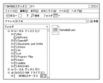
図3は、PC120がマスストレージメモリ111をマウントした状態を例示的に示す図である。ここでは、マスストレージメモリ111をFドライブとしてマウントし、当該FドライブにはリモートUIプログラム111aである”RemoteUI.exe”が格納されている。
FIG. 3 is a diagram exemplarily showing a state in which the
ステップS205では、PC120はリモートUIプログラム111aの実行を開始する。具体的には、PC120がユーザによる操作(”RemoteUI.exe”アイコンのマウスによるダブルクリックなど)を受け付けることにより開始される。これにより、”RemoteUI.exe”がPC120のRAM127に読み込まれCPU125により実行されることになる。
In step S205, the
ステップS206では、PC120はユーザによるリモートUIプログラム111aの操作に基づいて、情報DB111bの参照あるいは変更を実行する。この動作の詳細は後述する。
In step S206, the
ステップS207では、PC120はリモートUIプログラム111aの実行を終了する。具体的には、PC120がユーザによる操作(”終了”ボタンのマウスによるクリックなど)を受け付けることにより終了される。ここで、リモートUIプログラム111aは実行(exe)形式であることから、この終了によってPC120のRAM127から自動的に削除される。
In step S207, the
<情報DBの閲覧・更新動作の詳細>
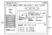
図4A〜図4Cは、リモートUIプログラム111aの操作画面の一例を示す図である。つまり、これらの画面はPC120の表示部130に表示される。前述のように、リモートUIプログラム111aはPC120上で動作可能なプログラムファイルである。PC120上でリモートUIプログラム111aを実行すると、MFP110の設定情報401やステータス402が表示される。また、ボタン群403の各ボタンを選択することにより、各項目における設定値の参照・変更を行う。
<Details of information DB browsing / update operations>
4A to 4C are diagrams illustrating an example of an operation screen of the
具体的には、PC120上で動作しているリモートUIプログラム111aは、情報DB111bファイルの読み出し・書き込みをPC120上から直接行うことにより上述の参照・変更を実現している。リモートUIプログラム111aファイルと同様に情報DB111bファイルもマスストレージメモリ111に格納されている。つまり、ステップS203でマウントするドライブと同一のドライブに格納されている。ただし、情報DB111bファイルはユーザによる誤操作を防止するため、ファイルシステムの機能を利用し不可視属性(隠しファイル属性)とするのが望ましい。
Specifically, the
つまり、上述のWebサーバを使用する技術(例えば特許文献2)においては、MFP内のWebサーバが情報DBの直接読み書きを行うが、本実施形態では、PC120上で動作するリモートUIプログラム111aが情報DBの直接読み書きを行う。また、上述の特許文献3の技術においてはマスストレージ機能を使用しているが、使用するドライバが従来型の専用ドライバであるため、インストールによってPCに常駐させる必要がある。しかし、本実施形態では、インストールは必要なく、PCに常駐させる必要も無い。
That is, in the above-described technology using the Web server (for example, Patent Document 2), the Web server in the MFP directly reads and writes the information DB, but in this embodiment, the
図8は、情報DB111bファイルを利用したリモートUIプログラムからの印刷動作のフローチャートである。 FIG. 8 is a flowchart of the printing operation from the remote UI program using the information DB 111b file.
ステップS801では、PC120は、リモートUIプログラム111aを起動する。起動が完了すると、前述の通り、リモートUIプログラム111aは、PC120の表示部130に操作画面(UI)を表示する。
In step S801, the
ステップS802では、UI(図4Cで示す印刷設定のダイアログボックス)を介して、ユーザから、用紙の種類や印刷品質、色や濃度といった印刷設定を受け付ける。初期表示では、情報DB111bに保存されている設定に基づき表示され、ユーザは変更が必要な項目について設定を変更する。 In step S802, print settings such as paper type, print quality, color, and density are received from the user via a UI (print setting dialog box shown in FIG. 4C). In the initial display, the information is displayed based on the settings stored in the information DB 111b, and the user changes the settings for items that need to be changed.
ステップS803では、リモートUIプログラムはユーザによって変更された設定値を情報DB111bに保存する。続けて印刷処理を行なう場合には、ステップS806に進む。一方、設定のみ行う場合には、ステップS804に進みリモートUIプログラムを終了させる。 In step S803, the remote UI program stores the setting value changed by the user in the information DB 111b. If the printing process is to be continued, the process proceeds to step S806. On the other hand, when only setting is performed, the process proceeds to step S804, and the remote UI program is terminated.
ステップS806では、図4Bに示すダイアログボックスにおいてプリントしたいファイル(以降プリントデータと称す)の指定をユーザから受け付ける。そして、不図示の”印刷実行ボタン”の押下を受け付けることで、プリントの指示とプリントデータを情報DB111bに保存し、ステップS807の印刷処理に進む。 In step S806, designation of a file to be printed (hereinafter referred to as print data) is received from the user in the dialog box shown in FIG. 4B. By accepting pressing of a “print execution button” (not shown), the print instruction and the print data are stored in the information DB 111b, and the process proceeds to the print processing in step S807.
図9は、印刷処理実行時の具体的なプリンタ設定値の取得フローチャートである。 FIG. 9 is a flowchart for acquiring a specific printer setting value when the printing process is executed.
ステップS911では、PC120からのリモートUIプログラムを通じて情報DB111bに保存されたプリント指示を検知する。例えば、制御部112の印刷モジュール112cが情報DB111bへの書き込みを定期的に監視することにより検知がなされる。
In step S911, a print instruction stored in the information DB 111b is detected through a remote UI program from the
ステップS912では、制御部112における印刷モジュール112cは情報DB111bからプリントデータの読み込みを開始する。
In step S912, the
ステップS913では、印刷モジュール112cは、ステップS802で設定された用紙の種類や印刷品質、色や濃度といった印刷設定も情報DB111bより読み込む。
In step S913, the
ステップS914では、印刷モジュール112cは印刷設定、および受信したプリントデータをプリンタエンジン113で処理可能な形式に展開(ラスタライズ処理など)し、印刷データをプリンタエンジン113に送信して終了する。
In step S914, the
なお、上述の説明においては情報DB111bをファイルであるとして説明を行ったが、制御部112へのメモリへアクセスするためのデータポートとして構成しても良い。
In the above description, the information DB 111b is described as a file. However, the information DB 111b may be configured as a data port for accessing the memory to the
図10は、データポートを利用したリモートUIプログラムからの印刷動作のフローチャートである。 FIG. 10 is a flowchart of a printing operation from a remote UI program using a data port.
ステップS1001では、PC120は、リモートUIプログラム111aを起動する。
In step S1001, the
ステップS1002では、リモートUIプログラム111aは、リモートUIに表示するプリンタの用紙の種類、印刷品質、色/濃度の現在の設定値を要求するコマンドをデータポート(情報DB111b)に送信する。
In step S1002, the
ステップS1003では、MFP110の制御部112は、設定値要求コマンドを受信するとそのレスポンスとして、要求されている当該設定値をメモリ112dから読み取り、データポート(情報DB111b)に返信する。
In step S1003, when the
ステップS1004では、リモートUIプログラム111aは、受信した設定値を表示部130上に、図4Cのごとく表示する。
In step S1004, the
ステップS1005では、UI(図4Cで示す印刷設定のダイアログボックス)を介して、設定値の変更をユーザから受け付けた場合、リモートUIプログラムは、設定値を変更するためのコマンドをデータポート(情報DB111b)に送信する。 In step S1005, when a change of the setting value is received from the user via the UI (print setting dialog box shown in FIG. 4C), the remote UI program sends a command for changing the setting value to the data port (information DB 111b). ).
ステップS1006では、制御部112は、受信した設定値変更のコマンドに従って、メモリ112bの設定値を変更する。続けて印刷処理を行なう場合には、ステップS1009に進む。一方、設定のみ行う場合には、ステップS1008に進みリモートUIプログラムを終了させる。
In step S1006, the
ステップS1009では、図4Bに示すダイアログボックスにおいてプリントデータの指定をユーザから受け付ける。そして、不図示の”印刷実行ボタン”の押下を受け付けることで、プリント要求のコマンドとプリントデータをデータポート(情報DB111b)に送信する。 In step S1009, designation of print data is accepted from the user in the dialog box shown in FIG. 4B. Then, by accepting pressing of a “print execution button” (not shown), a print request command and print data are transmitted to the data port (information DB 111b).
ステップS1010では、プリント要求のコマンドを受けた印刷モジュール112cは、併せて受信したプリントデータを、メモリ112bに保存されている用紙種類、印刷品質、色/濃度の設定値に従ってプリント処理する。
In step S1010, the
図7は、従来のプリンタ専用ドライバの構成要素を示す図である。従来のプリンタ専用ドライバは構成要素として、UI部701、ドライバ本体702、スプーラ703、ランゲージモニター704を備える。そして、これらの構成要素の全てをPC120にインストールし、RAM127上で実行する必要がある。ただし、Windows(登録商標)OSでは、スプーラ703はOSの構成要素として提供される。
FIG. 7 is a diagram showing components of a conventional printer driver. A conventional printer driver includes a
本実施形態では、リモートUIプログラム111aが従来のUI部701の機能に相当し、印刷モジュール112cがドライバ本体702およびランゲージモニター704の機能に相当する。つまり、上述の構成要素全て(例えば10Mbyte〜20Mbyte)をPC120へ送る従来の場合に比較し、極めて少ないデータ容量のリモートUIプログラム111aのみをPC120上で起動させるだけで良い。そのため、PC120上で利用する領域の容量を数Mbyte程度にまで、削減することが可能となる。
In the present embodiment, the
以上説明したように、周辺装置(MFP)に、PCから外部記憶装置としてアクセス可能な領域を設け、当該領域に、接続したPCから直接実行可能なリモートUIプログラムファイルを格納する。また、外部記憶装置としてアクセス可能な領域に、MFPを制御するための設定値を含むデータベース(DB)ファイルを併せて格納する。このように構成することにより、リモートUIプログラムを介してDBファイル内の設定値を直接参照あるいは変更することができる。そのため、内部の実装負荷を低減しつつ当該周辺装置へのより簡単なアクセスを実現可能とする技術を提供することができる。 As described above, an area accessible as an external storage device from a PC is provided in the peripheral device (MFP), and a remote UI program file that can be directly executed from the connected PC is stored in the area. In addition, a database (DB) file including setting values for controlling the MFP is also stored in an area accessible as an external storage device. With this configuration, the setting value in the DB file can be directly referred to or changed via the remote UI program. For this reason, it is possible to provide a technique that enables easier access to the peripheral device while reducing the internal mounting load.
(変形例)
<概要>
機能構成は図1とほぼ同様であるが、マスストレージメモリがネットワーク共有機能により構成される点が異なる。
(Modification)
<Overview>
The functional configuration is almost the same as that in FIG. 1, except that the mass storage memory is configured by a network sharing function.
<システム構成>
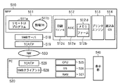
図5は、変形例に係るに係るMFPおよびPCの内部モジュール構成を示す図である。なお、変形例において、MFP510とPC520とは、TCP/IPネットワーク(NW)530によりネットワーク接続される。以下では、図1と異なる部分についてのみ説明を行う。
<System configuration>
FIG. 5 is a diagram showing an internal module configuration of the MFP and the PC according to the modification. In the modification, the
510および529は、それぞれ、MFP510およびPC520におけるTCP/IPスタックである。また、518および528は、それぞれ、ファイル共有プロトコル(SMBプロトコルなど)に基づくファイル共有機能を提供するサーバおよびクライアントである。つまり、MFP510は、NW530に接続された装置に対してマスストレージメモリ511を共有ドライブ(あるいは共有フォルダ)として提供している。
510 and 529 are TCP / IP stacks in the
PC520は、SMBクライアント528によりNW530上の共有ドライブを探索・接続する機能を持っている。つまり、IPアドレスの指定などを必要とせず、MFP510を探索することが出来る。
The
<動作フロー>
図6は、変形例に係るMFPおよびPCの動作フローチャートである。特に、MFP510とPC520とを接続し、PC520からMFP510内部の設定値を参照・変更する際の動作について説明する。
<Operation flow>
FIG. 6 is an operation flowchart of the MFP and the PC according to the modification. In particular, an operation when the
ステップS601では、MFP510およびPC520をそれぞれNW530に接続する。つまり、MFP510およびPC520がそれぞれTCP/IPによりNW530に接続された他の端末と通信可能となるように接続する。
In step S601,
ステップS602では、SMBサーバ518は、NW530に対してSMBプロトコルに基づいて共有ドライブとしてマスストレージメモリ511を有していることをアナウンスする。
In step S602, the
ステップS603では、PC520はSMBクライアント528を介してマスストレージメモリ511をドライブとしてマウントする。具体的には、PC520内のCPU525およびOS526がこの動作を実行する。つまり、ステップS602によるアナウンスの受信に基づいて、マスストレージメモリ511を新規のドライブとしてマウントする。
ステップS604では、PC520は、リモートUIプログラム511aを可視状態とする。具体的には、ステップS603においてマウントしたドライブ内のファイルのリストを表示部540に表示する。
In step S603, the
In step S604, the
ステップS605では、PC520はリモートUIプログラム511aの実行を開始する。具体的には、PC520がユーザによる操作(”RemoteUI.exe”アイコンのマウスによるダブルクリックなど)を受け付けることにより開始される。これにより、”RemoteUI.exe”がPC520のRAM527に読み込まれCPU525により実行されることになる。
In step S605, the
ステップS606では、PC520はユーザによるリモートUIプログラム511aの操作に基づいて、情報DB511bの参照あるいは変更を実行する。
In step S606, the
ステップS607では、PC520はリモートUIプログラム511aの実行を終了する。具体的には、PC520がユーザによる操作(”終了”ボタンのマウスによるクリックなど)を受け付けることにより終了される。
In step S607, the
以上説明したように、変形例に係るMFPの構成とすることにより、第1実施形態と同様、周辺装置(MFP)内部の実装負荷を低減しつつ当該周辺装置へのより簡単なアクセスを実現可能とする技術を提供することができる。 As described above, by adopting the configuration of the MFP according to the modification, as in the first embodiment, it is possible to achieve easier access to the peripheral device while reducing the mounting load inside the peripheral device (MFP). Can be provided.
(他の実施形態)
以上、本発明の実施形態について詳述したが、本発明は、複数の機器から構成される情報処理システムに適用しても良いし、また、一つの機器からなる装置に適用しても良い。また、ローカルI/Fの種類としては、USBI/Fに限らずマスストレージ機能を有するインターフェースならば同様の動作が可能であり、本発明の技術的範囲に含まれる。
(Other embodiments)
The embodiment of the present invention has been described in detail above. However, the present invention may be applied to an information processing system including a plurality of devices, or may be applied to an apparatus including a single device. Further, the type of local I / F is not limited to the USB I / F, and any interface having a mass storage function can perform the same operation, and is included in the technical scope of the present invention.
なお、本発明は、前述した実施形態の機能を実現するプログラムを、システム或いは装置に直接或いは遠隔から供給し、そのシステム或いは装置が、供給されたプログラムコードを読み出して実行することによっても達成される。従って、本発明の機能処理をコンピュータで実現するために、コンピュータにインストールされるプログラムコード自体も本発明の技術的範囲に含まれる。 The present invention can also be achieved by supplying a program that realizes the functions of the above-described embodiments directly or remotely to a system or apparatus, and the system or apparatus reads and executes the supplied program code. The Accordingly, the program code itself installed in the computer in order to realize the functional processing of the present invention by the computer is also included in the technical scope of the present invention.
Claims (6)
前記電子機器の動作条件を設定する動作条件情報ファイルと、前記情報処理装置により実行され前記動作条件情報ファイルを参照または変更するためのユーザインターフェースを表示させるプログラムのそれぞれを記憶する記憶手段と、
前記通信手段を介して前記情報処理装置と通信状態になったとき、前記記憶手段を前記情報処理装置の外部記憶装置として機能させる制御手段と、
を備え、前記動作条件情報ファイルの内容に従って動作することを特徴とする電子機器。 An electronic device that functions as a peripheral device of an information processing device and includes communication means for communicating with the information processing device,
An operating condition information file for setting operating conditions of the electronic device; and storage means for storing a program that is executed by the information processing apparatus and displays a user interface for referring to or changing the operating condition information file;
Control means for causing the storage means to function as an external storage device of the information processing apparatus when in communication with the information processing apparatus via the communication means;
And an electronic device that operates according to the contents of the operating condition information file.
前記制御手段は、前記情報処理装置に対し前記記憶手段を前記ローカルインタフェース接続におけるマスストレージクラス規格に基づいた外部記憶装置として機能させることを特徴とする請求項1に記載の電子機器。 The communication means is a local interface connection;
The electronic device according to claim 1, wherein the control unit causes the information processing apparatus to function as the external storage device based on a mass storage class standard in the local interface connection.
前記制御手段は、前記情報処理装置に対し前記記憶手段をファイル共有プロトコルに基づいた外部記憶装置として機能させることを特徴とする請求項1に記載の電子機器。 The communication means is a network connection;
The electronic device according to claim 1, wherein the control unit causes the information processing apparatus to function as the external storage device based on a file sharing protocol.
前記電子機器は、
前記電子機器の動作条件を設定する動作条件情報ファイルと、前記情報処理装置により実行され前記動作条件情報を参照または変更するためのユーザインターフェースを表示させるプログラムのそれぞれを記憶する記憶手段と、
前記通信手段を介して前記情報処理装置と通信状態になったとき、前記記憶手段を前記情報処理装置の外部記憶装置として機能させる制御手段と、
を備え、前記電子機器は前記動作条件情報ファイルの内容に従って動作することを特徴とする情報処理システム。 An information processing system including an information processing device and an electronic device that functions as a peripheral device of the information processing device and includes a communication unit that communicates with the information processing device,
The electronic device is
An operating condition information file for setting operating conditions of the electronic device; and storage means for storing a program that is executed by the information processing apparatus and displays a user interface for referring to or changing the operating condition information;
Control means for causing the storage means to function as an external storage device of the information processing apparatus when being in communication with the information processing apparatus via the communication means;
The information processing system is characterized in that the electronic device operates according to the contents of the operation condition information file.
Priority Applications (2)
| Application Number | Priority Date | Filing Date | Title |
|---|---|---|---|
| JP2007286687A JP2008159033A (en) | 2006-11-30 | 2007-11-02 | Electronic apparatus and information processing system |
| US11/946,352 US20080133743A1 (en) | 2006-11-30 | 2007-11-28 | Electronic apparatus and information processing system |
Applications Claiming Priority (2)
| Application Number | Priority Date | Filing Date | Title |
|---|---|---|---|
| JP2006324691 | 2006-11-30 | ||
| JP2007286687A JP2008159033A (en) | 2006-11-30 | 2007-11-02 | Electronic apparatus and information processing system |
Publications (2)
| Publication Number | Publication Date |
|---|---|
| JP2008159033A true JP2008159033A (en) | 2008-07-10 |
| JP2008159033A5 JP2008159033A5 (en) | 2010-12-16 |
Family
ID=39659832
Family Applications (1)
| Application Number | Title | Priority Date | Filing Date |
|---|---|---|---|
| JP2007286687A Pending JP2008159033A (en) | 2006-11-30 | 2007-11-02 | Electronic apparatus and information processing system |
Country Status (1)
| Country | Link |
|---|---|
| JP (1) | JP2008159033A (en) |
Cited By (11)
| Publication number | Priority date | Publication date | Assignee | Title |
|---|---|---|---|---|
| JP2009255482A (en) * | 2008-04-21 | 2009-11-05 | Brother Ind Ltd | Printing device |
| JP2010055438A (en) * | 2008-08-29 | 2010-03-11 | Brother Ind Ltd | Radio configuration system and printer |
| JP2010082927A (en) * | 2008-09-30 | 2010-04-15 | Brother Ind Ltd | Printing apparatus |
| JP2010082924A (en) * | 2008-09-30 | 2010-04-15 | Brother Ind Ltd | Printing apparatus |
| JP2010089287A (en) * | 2008-10-03 | 2010-04-22 | Canon Inc | Printing apparatus |
| JP2010118003A (en) * | 2008-11-14 | 2010-05-27 | Canon Electronics Inc | Image reader and method of controlling the same |
| JP2011028739A (en) * | 2009-07-03 | 2011-02-10 | Canon Electronics Inc | Peripheral device |
| JP2011175181A (en) * | 2010-02-25 | 2011-09-08 | Brother Industries Ltd | Image forming apparatus |
| US8615613B2 (en) | 2009-07-03 | 2013-12-24 | Canon Denshi Kabushiki Kaisha | Program executed in information processing apparatus to control peripheral apparatus |
| JP2014044746A (en) * | 2013-11-25 | 2014-03-13 | Canon Inc | Communication device, and control method of the same |
| US8914558B2 (en) | 2009-11-25 | 2014-12-16 | Canon Denshi Kabushiki Kaisha | Peripheral device usable without installing driver in computer beforehand |
Citations (4)
| Publication number | Priority date | Publication date | Assignee | Title |
|---|---|---|---|---|
| JP2003110555A (en) * | 2001-09-28 | 2003-04-11 | Sony Corp | System and method for processing information on network |
| JP2006031345A (en) * | 2004-07-15 | 2006-02-02 | Canon Inc | Device apparatus for performing i/o control by using mass storage class protocol |
| JP2006256041A (en) * | 2005-03-16 | 2006-09-28 | Ricoh Co Ltd | Image forming device and image forming method |
| JP2006293638A (en) * | 2005-04-08 | 2006-10-26 | Canon Inc | Information processor and peripheral equipment |
-
2007
- 2007-11-02 JP JP2007286687A patent/JP2008159033A/en active Pending
Patent Citations (4)
| Publication number | Priority date | Publication date | Assignee | Title |
|---|---|---|---|---|
| JP2003110555A (en) * | 2001-09-28 | 2003-04-11 | Sony Corp | System and method for processing information on network |
| JP2006031345A (en) * | 2004-07-15 | 2006-02-02 | Canon Inc | Device apparatus for performing i/o control by using mass storage class protocol |
| JP2006256041A (en) * | 2005-03-16 | 2006-09-28 | Ricoh Co Ltd | Image forming device and image forming method |
| JP2006293638A (en) * | 2005-04-08 | 2006-10-26 | Canon Inc | Information processor and peripheral equipment |
Cited By (11)
| Publication number | Priority date | Publication date | Assignee | Title |
|---|---|---|---|---|
| JP2009255482A (en) * | 2008-04-21 | 2009-11-05 | Brother Ind Ltd | Printing device |
| JP2010055438A (en) * | 2008-08-29 | 2010-03-11 | Brother Ind Ltd | Radio configuration system and printer |
| JP2010082927A (en) * | 2008-09-30 | 2010-04-15 | Brother Ind Ltd | Printing apparatus |
| JP2010082924A (en) * | 2008-09-30 | 2010-04-15 | Brother Ind Ltd | Printing apparatus |
| JP2010089287A (en) * | 2008-10-03 | 2010-04-22 | Canon Inc | Printing apparatus |
| JP2010118003A (en) * | 2008-11-14 | 2010-05-27 | Canon Electronics Inc | Image reader and method of controlling the same |
| JP2011028739A (en) * | 2009-07-03 | 2011-02-10 | Canon Electronics Inc | Peripheral device |
| US8615613B2 (en) | 2009-07-03 | 2013-12-24 | Canon Denshi Kabushiki Kaisha | Program executed in information processing apparatus to control peripheral apparatus |
| US8914558B2 (en) | 2009-11-25 | 2014-12-16 | Canon Denshi Kabushiki Kaisha | Peripheral device usable without installing driver in computer beforehand |
| JP2011175181A (en) * | 2010-02-25 | 2011-09-08 | Brother Industries Ltd | Image forming apparatus |
| JP2014044746A (en) * | 2013-11-25 | 2014-03-13 | Canon Inc | Communication device, and control method of the same |
Similar Documents
| Publication | Publication Date | Title |
|---|---|---|
| JP2008159033A (en) | Electronic apparatus and information processing system | |
| KR101337160B1 (en) | Information processing apparatus, information processing method and storage medium | |
| JP5857611B2 (en) | Information processing device, system, program | |
| JP4861883B2 (en) | Image forming apparatus and application execution method | |
| JP4844871B2 (en) | Program for creating installer, storage medium for storing the program, installer creation method, information processing apparatus | |
| US20080068655A1 (en) | Data processing apparatus and recording medium | |
| JP5321929B2 (en) | Universal device driver, device control program, information processing apparatus, server apparatus, and method | |
| JP5293035B2 (en) | Data processing apparatus, data processing method, program, and recording medium | |
| JP2011065368A (en) | Print control device, print control method, and computer program | |
| JP2017102901A (en) | Program, information processing device, setting method, and information processing system | |
| US20110176170A1 (en) | Printing apparatus, printing system, and control method | |
| JP4944812B2 (en) | Information processing system, information processing method, and program | |
| US20120236354A1 (en) | Information processing apparatus, information processing method, and program | |
| US9606761B2 (en) | Information processing apparatus for controlling an output process and method for the same | |
| JP4991820B2 (en) | Client device with expandable image processing device driver and method for implementing the same | |
| US8422040B2 (en) | Image forming system and method, management apparatus, and recording medium | |
| US7418701B2 (en) | Network device and setup method thereof | |
| JP2008171096A (en) | Information processor with update function | |
| JP2004171517A (en) | Data processor | |
| US20100238486A1 (en) | System and method for printing independent of location and using a universal print module | |
| US20080133743A1 (en) | Electronic apparatus and information processing system | |
| JP5707893B2 (en) | Information processing apparatus, information processing system, information processing method, and information processing program | |
| JP5215802B2 (en) | Printing device | |
| US20190124212A1 (en) | Image forming apparatus, information processing method, and program | |
| JP2010009097A (en) | Network system and printer driver |
Legal Events
| Date | Code | Title | Description |
|---|---|---|---|
| A521 | Written amendment |
Free format text: JAPANESE INTERMEDIATE CODE: A523 Effective date: 20101102 |
|
| A621 | Written request for application examination |
Free format text: JAPANESE INTERMEDIATE CODE: A621 Effective date: 20101102 |
|
| A977 | Report on retrieval |
Free format text: JAPANESE INTERMEDIATE CODE: A971007 Effective date: 20120126 |
|
| A131 | Notification of reasons for refusal |
Free format text: JAPANESE INTERMEDIATE CODE: A131 Effective date: 20120130 |
|
| A02 | Decision of refusal |
Free format text: JAPANESE INTERMEDIATE CODE: A02 Effective date: 20120608 |