JP2008157573A - Rotary cleaning body for air conditioner, and air conditioner - Google Patents
Rotary cleaning body for air conditioner, and air conditioner Download PDFInfo
- Publication number
- JP2008157573A JP2008157573A JP2006348696A JP2006348696A JP2008157573A JP 2008157573 A JP2008157573 A JP 2008157573A JP 2006348696 A JP2006348696 A JP 2006348696A JP 2006348696 A JP2006348696 A JP 2006348696A JP 2008157573 A JP2008157573 A JP 2008157573A
- Authority
- JP
- Japan
- Prior art keywords
- air conditioner
- cleaning body
- rotary cleaning
- air
- dust
- Prior art date
- Legal status (The legal status is an assumption and is not a legal conclusion. Google has not performed a legal analysis and makes no representation as to the accuracy of the status listed.)
- Pending
Links
Images


Abstract
Description
本発明は、空気調和機に取り付けられたエアフィルターの清掃を行う空気調和機の回転清掃体と、それを用いた空気調和機に関するものである。 The present invention relates to a rotary cleaning body of an air conditioner for cleaning an air filter attached to the air conditioner, and an air conditioner using the same.
従来の空気調和機には、吸込口と熱交換器との間に、空気調和機本体内部への塵埃侵入を防ぐためにエアフィルターが配置されており、空気調和機の運転に伴い吸込口から空気と共に侵入する塵埃を捉える機能を有している。このため、エアフィルターには捉えた塵埃が徐々に付着するとともに、目が徐々に詰まってしまい風量を低下させてしまうので、空気調和機本体から着脱可能に構成され、定期的にエアフィルター表面を電気掃除機等で吸引したり、洗浄したりしなければならなかった。 In a conventional air conditioner, an air filter is disposed between the suction port and the heat exchanger to prevent dust from entering the air conditioner body, and air flows from the suction port as the air conditioner operates. And has a function of catching intruding dust. For this reason, the dust caught on the air filter gradually adheres and the eyes gradually clog and reduce the air volume. It had to be sucked and cleaned with a vacuum cleaner.
これに対し、エアフィルターの上流側表面に沿って移動することができる吸引口を有する吸引ノズルと、この吸引ノズルに連結された吸引装置を空気調和機本体に設けて、吸引口からエアフィルター表面に付着した塵埃を吸引することで、エアフィルターを取り外すことなくエアフィルターの自動清掃が行える構造が考案されている(例えば、特許文献1参照)。 On the other hand, a suction nozzle having a suction port that can move along the upstream surface of the air filter, and a suction device connected to the suction nozzle are provided in the air conditioner body, and the air filter surface extends from the suction port. A structure has been devised that can automatically clean the air filter without removing the air filter by sucking the dust adhering to the surface (see, for example, Patent Document 1).
また、フィルターのメンテナンスの手間を低減する目的で、円盤状のエアフィルターと、このエアフィルターの表面に接する回転ブラシと、エアフィルターを回転駆動する駆動ユニットを設け、前記駆動ユニットを駆動することでエアフィルターを回転させながら、その表面に堆積した塵埃を、回転ブラシを回転させて掻きとるようにした空気調和機がある(例えば、特許文献2参照)。 For the purpose of reducing the maintenance work of the filter, a disk-shaped air filter, a rotating brush in contact with the surface of the air filter, and a drive unit for rotating the air filter are provided, and the drive unit is driven. There is an air conditioner in which dust accumulated on the surface of an air filter is scraped by rotating a rotary brush while rotating the air filter (see, for example, Patent Document 2).
しかしながら、上記特許文献1に開示されたような従来の空気調和機においては、吸引口の開閉面積を絞ることで風量を落として、吸引圧力を高めている。このような吸引ノズルで塵埃を除去しようとすると、エアフィルター表面に浮いたような状態で乗っている綿埃等は容易に吸引できるが、吸引力のみでは、エアフィルターの網目に絡んだ塵埃や、油分を含む塵埃等を、清掃ブラシのように掻き出して剥離させることはできず、エアフィルターにこびりついた塵埃を確実に除去することは非常に困難であった。
However, in the conventional air conditioner disclosed in
また、上記特許文献2に開示されたような従来の空気調和機においては、回転ブラシ芯棒の外周全体に植毛されているブラシ毛が同じ種類の同じ毛丈のものであり、塵埃がブラシ毛に絡みつき、回転ブラシが汚れることから、エアフィルターが汚れてしまい、清掃効果も減少するものであった。
Further, in the conventional air conditioner disclosed in
本発明は上記点に鑑み、エアフィルターに付着した塵埃を効率よく除去することができると共に、清掃体に塵埃が絡みつくことを防ぐことができる空気調和機の回転清掃体及び空気調和機を提供することを目的とする。 In view of the above points, the present invention provides a rotary cleaning body and an air conditioner for an air conditioner that can efficiently remove dust adhering to an air filter and can prevent dust from getting entangled with the cleaning body. For the purpose.
請求項1の発明は、空気調和機本体に設けられた吸込口と吹出口を結ぶ空気通路に配置された除塵用のエアフィルターに付着した塵埃を除去する空気調和機の回転清掃体において、該回転清掃体は、毛腰の異なる2種類以上の清掃体を棒状の芯棒の外周面に固着したことに特徴を有する。したがって、毛腰の強い方の清掃体でエアフィルターの網目にこびりついた塵埃を掻き取り、毛腰の弱い方の清掃体でエアフィルターの表面に付着した塵埃を満遍なく拭き取ることができる。
The invention of
請求項2の発明は、空気調和機本体に設けられた吸込口と吹出口を結ぶ空気通路に配置された除塵用のエアフィルターに付着した塵埃を除去する空気調和機の回転清掃体において、該回転清掃体は、毛丈の異なる2種類以上の清掃体を棒状の芯棒の外周面に固着したことに特徴を有する。したがって、毛丈が長い方の清掃体でエアフィルターの網目に入り込んだ塵埃を表面に掻き出し、毛丈が短い方の清掃体でエアフィルターの表面の塵埃を満遍なく拭き取ることができる。 According to a second aspect of the present invention, there is provided a rotary cleaning body for an air conditioner that removes dust adhering to an air filter for dust removal disposed in an air passage that connects a suction port and an outlet provided in an air conditioner body. The rotary cleaning body is characterized in that two or more types of cleaning bodies having different bristle lengths are fixed to the outer peripheral surface of a rod-shaped core bar. Therefore, the dust having entered the mesh of the air filter can be scraped to the surface by the cleaning body having a longer bristle length, and the dust on the surface of the air filter can be wiped evenly by the cleaning body having the shorter bristle length.
請求項3の発明は、空気調和機本体に設けられた吸込口と吹出口を結ぶ空気通路に配置された除塵用のエアフィルターに付着した塵埃を除去する空気調和機の回転清掃体において、該回転清掃体は、毛腰と毛丈の異なる2種類以上の清掃体を棒状の芯棒の外周面に固着したことに特徴を有する。したがって、毛腰の強い方の清掃体でエアフィルターの網目にこびりついた塵埃を掻き取り、毛丈が長い方の清掃体でエアフィルターの網目に入り込んだ塵埃を表面に掻き出し、毛腰の弱い方の清掃体又は毛丈が短い方の清掃体でエアフィルターの表面に付着した塵埃を満遍なく拭き取ることができる。 According to a third aspect of the present invention, there is provided a rotary cleaning body for an air conditioner that removes dust adhering to an air filter for dust removal disposed in an air passage that connects a suction port and an outlet provided in an air conditioner body. The rotary cleaning body is characterized in that two or more types of cleaning bodies having different fur and hair lengths are fixed to the outer peripheral surface of a rod-shaped core bar. Therefore, scrape dust that has stuck to the air filter mesh with a cleaner body with a bristle and waist, scrape dust that has entered the air filter mesh with a cleaner body with longer hair length, The dust adhering to the surface of the air filter can be wiped off evenly with the cleaning body of this or the cleaning body with shorter hair length.
請求項4の発明は、請求項1から3のいずれか1項の発明において、2種類以上の清掃体は毛幅が異なることに特徴を有する。したがって、毛腰の強い清掃体、毛腰の弱い清掃体、毛丈が長い清掃体及び、毛丈が短い清掃体を各々最適な比率で棒状の芯棒の外周面に固着することができるので、さらに清掃効果を向上させることができる。
The invention of
請求項5の発明は、空気調和機本体に設けられた吸込口と吹出口を結ぶ空気通路に配置された除塵用のエアフィルターに付着した塵埃を除去する空気調和機の回転清掃体において、該回転清掃体は、清掃体の長手方向に断続的に切欠き部を設けた、少なくとも1つの前記清掃体を棒状の芯棒の外周面に固着したことに特徴を有する。したがって、清掃体によってエアフィルターに付着した塵埃を掻き出すと共に、切欠き部で塵埃を集塵ケースに捕集し、空気調和機の外部へ排出することができる。 According to a fifth aspect of the present invention, there is provided a rotary cleaning body for an air conditioner that removes dust adhering to an air filter for dust removal disposed in an air passage connecting a suction port and an outlet provided in an air conditioner body. The rotary cleaning body is characterized in that at least one cleaning body provided with notches intermittently in the longitudinal direction of the cleaning body is fixed to the outer peripheral surface of the rod-shaped core rod. Therefore, the dust adhered to the air filter can be scraped out by the cleaning body, and the dust can be collected in the dust collection case by the notch and discharged to the outside of the air conditioner.
請求項6の発明は、請求項1から5のいずれか1項の発明において、2種類以上の清掃体は、棒状の芯棒の外周面に螺旋状に固着したことに特徴を有する。したがって、清掃体に付着した塵埃を螺旋に沿って一方向に設置された集塵ケースに捕集し、空気調和機の外部へ排出することができる。
The invention of
請求項7の発明は、請求項1から6のいずれか1項に記載の回転清掃体を有する空気調和機に特徴を有する。したがって、エアフィルターに付着した塵埃を効率よく空気調和機の外部へ排出することができる空気調和機である。
The invention of
請求項1から3の発明では、回転清掃体の芯棒の外周面に固着した清掃体を毛腰或いは毛丈を異ならせた2種類以上のものを使用することによって、エアフィルターに付着した塵埃を確実に除去することができる。また、請求項4の発明では、2種類以上の清掃体の毛幅を異ならせることによって最適な比率を選択でき、清掃効果をより一層向上させることができる。さらに、請求項5の発明では、切欠き部によって、塵埃を集塵ケースに捕集することができる。また、断続的に清掃体があることで、フィルターを叩く効果が得られ、掻き出し力が向上する。また、請求項6の発明では、清掃体を螺旋状に棒状の芯棒に固着することによって、一方向に塵埃を移動させることができ、同面積の清掃体が、フィルターに常に一定に当たることになるので、回転時に受ける負荷が一定になることで、回転ムラが無くなり騒音も軽減される。そして、常に一定の負荷がかかるので、負荷変動が無くなり、駆動源への負荷が軽減される。また、回転清掃体の組立てが容易になる。さらに、請求項7の発明では、上記請求項1から6の構成を備えた回転清掃体を有する空気調和機であることから、エアフィルターに付着した塵埃を効率よく除去することができると共に、清掃体に塵埃が絡みつくことを防ぐことができる空気調和機を提供できる。
In the first to third aspects of the invention, the dust adhered to the air filter can be obtained by using two or more types of cleaning bodies fixed on the outer peripheral surface of the core rod of the rotary cleaning body and having different hairs or lengths. Can be reliably removed. Moreover, in invention of
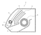
次に、本発明の実施形態を図面に基づいて説明する。図1は本発明の第1実施形態における空気調和機の回転清掃体を搭載した空気調和機の縦断面図である。図1において、空気調和機本体1は、熱交換器4と、室内の空気を取り入れる吸込口2と、熱交換器4と吸込口2との間に配され、吸込口2から流入する空気中に含まれる塵埃を捕集するエアフィルター5と、このエアフィルター5の上流側に配されると共に、エアフィルター5で捕集された塵埃を除去する清掃装置を有し、この清掃装置は、回転清掃体7と、この回転清掃体7を回転させるための回転駆動手段(図示せず)と、回転清掃体7をエアフィルター5の上流側の表面に沿って上下方向に移動させる上下移動手段(図示せず)にて形成されてあり、室内の空気を吸込口2から吸収し、エアフィルター5、熱交換器4を通して吹出口3から熱交換された空気を室内に吹き出す送風ファン6とを備えている。回転清掃体7により除去された塵埃は、集塵ケース23に捕集され、空気調和機の外部に排出される。
Next, embodiments of the present invention will be described with reference to the drawings. FIG. 1 is a longitudinal sectional view of an air conditioner equipped with a rotary cleaning body of an air conditioner according to a first embodiment of the present invention. In FIG. 1, an air conditioner
図2は本発明の空気調和機の回転清掃体を構成する各部品の斜視図である。図2(a)は清掃体である起毛布の斜視図であり、図2(b)はパイプからなる芯棒の斜視図である。図2(a)に示すように、本発明の清掃体の一例として、起毛布8を用いることができる。起毛布8は、基部9と、この基部9に植毛されたブラシ部10とからなるものである。この起毛布8の基部9を図2(b)に示す芯棒11の外周面に接着材等で固着して回転清掃体は製作される。尚、芯棒11は棒状のものであればよく、この図に示すような中空部を有するパイプ状のものの他に中空部のないものであってもよく、角材を使用することも可能である。
FIG. 2 is a perspective view of each component constituting the rotary cleaning body of the air conditioner of the present invention. Fig.2 (a) is a perspective view of the raising cloth which is a cleaning body, FIG.2 (b) is a perspective view of the core rod which consists of a pipe. As shown to Fig.2 (a), the raising
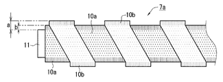
図3は本発明の第1実施形態における空気調和機の回転清掃体の正面図である。回転清掃体7aは芯棒11の外周面に毛腰が異なる清掃体のブラシ部10aと、10bとが正面から見た場合に交互に現れるように螺旋状に固着されている。ここで、毛腰が異なるとは、ブラシ部10a、10bの線径、材質、疎密(基部9に植毛される密度)を異ならせることによって、実現することができる。このように、毛腰を異ならせることによって、毛腰の強い方の清掃体でエアフィルターの網目にこびりついた塵埃を掻き取り、毛腰の弱い方の清掃体でエアフィルターの表面に付着した塵埃を満遍なく拭き取ることができる。また、清掃体のブラシ部10aの毛丈は芯棒11の外周面からの長さbであり、清掃体のブラシ部10bの毛丈は芯棒11の外周面からの長さaである。このように、ブラシ部10aと10bの毛丈を異ならせることによって毛丈が長い方の清掃体のブラシ部10bでエアフィルターの網目に入り込んだ塵埃を表面に掻き出し、毛丈が短い方の清掃体のブラシ部10aでエアフィルターの表面の塵埃を満遍なく拭き取ることができる。
FIG. 3 is a front view of the rotary cleaning body of the air conditioner according to the first embodiment of the present invention. The
図4は本発明の第2実施形態における空気調和機の回転清掃体を構成する清掃体の正面図(a)と、回転清掃体の側面図(b)である。本実施形態においては、清掃体である起毛布8aの基部9にブラシ部10cが、長手方向に断続的に切欠き部12を設けつつ植毛されている。このように、切欠き部12を設けた状態で、起毛布8aの基部9を芯棒11に固着して回転清掃体7bを製作する。この回転清掃体7bは切欠き部12を有することによって、ブラシ部10cでエアフィルターに付着した塵埃を掻き出すと共に、切欠き部12で塵埃を図1で示した集塵ケース23に捕集し、空気調和機の外部へと排出することができる。尚、本実施形態における清掃体8aは、少なくとも1つあればよい。
FIG. 4: is the front view (a) of the cleaning body which comprises the rotary cleaning body of the air conditioner in 2nd Embodiment of this invention, and the side view (b) of a rotary cleaning body. In this embodiment, the
図5は本発明の第3実施形態における空気調和機の回転清掃体の正面図である。この図に示す回転清掃体7cは芯棒11の外周面に毛腰が異なる清掃体のブラシ部10dと、10eとが正面から見た場合に交互に現れるように螺旋状に固着されている。このように、毛腰を異ならせることによって、毛腰の強い方の清掃体でエアフィルターの網目にこびりついた塵埃を掻き取り、毛腰の弱い方の清掃体でエアフィルターの表面に付着した塵埃を満遍なく拭き取ることができる。また、清掃体のブラシ部10dの毛丈は芯棒11の外周面からの長さbであり、清掃体のブラシ部10eの毛丈は芯棒11の外周面からの長さaである。このように、ブラシ部10dと10eの毛丈を異ならせることによって毛丈が長い方の清掃体のブラシ部10eでエアフィルターの網目に入り込んだ塵埃を表面に掻き出し、毛丈が短い方の清掃体のブラシ部10dでエアフィルターの表面の塵埃を満遍なく拭き取ることができる。さらに、ブラシ部10dの毛幅をdとし、ブラシ部10eの毛幅をcとして毛幅を異ならせている。このように、毛幅を異ならせることによって、毛腰の強い清掃体、毛腰の弱い清掃体、毛丈が長い清掃体及び、毛丈が短い清掃体を各々最適な比率で棒状の芯棒11の外周面に固着することができるので、清掃効果を一層向上させることができるのである。また、ブラシ部10eには長手方向に断続的に切欠き部12を設けているので、ブラシ部10d及び10eで掻き出した塵埃を切欠き部12から図1で示した集塵ケース23に捕集し、空気調和機の外部へと排出することができる。
FIG. 5 is a front view of the rotary cleaning body of the air conditioner according to the third embodiment of the present invention. The
尚、本発明の趣旨を逸脱しない範囲において、種々の実施形態をとることができることは言うまでもない。例えば、上記第1実施形態と第3実施形態においては、起毛布を芯棒に螺旋状に固着している。これによって塵埃を螺旋に沿って一方向に設置された集塵ケースに捕集することができるものであるが、これに限定されるものではなく、様々な形状を適用することが可能である。 In addition, it cannot be overemphasized that various embodiment can be taken in the range which does not deviate from the meaning of this invention. For example, in the said 1st Embodiment and 3rd Embodiment, the raising cloth is firmly fixed to the core rod in a spiral shape. Thus, the dust can be collected in a dust collecting case installed in one direction along the spiral, but is not limited to this, and various shapes can be applied.
本発明の空気調和機の回転清掃体及び空気調和機は主に室内の冷房、暖房、除湿等を行う空気調和機として、又は、この空気調和機のエアフィルターの清掃のために利用される。 The rotary cleaner and the air conditioner of the present invention are mainly used as an air conditioner that performs indoor cooling, heating, dehumidification, etc., or for cleaning an air filter of the air conditioner.
1 空気調和機本体
2 吸込口
3 吹出口
4 熱交換器
5 エアフィルター
6 送風ファン
7、7a、7b、7c 回転清掃体
8、8a 清掃体
9 基部
10、10a、10b、10c、10d、10e ブラシ部
11 芯棒
12 切欠き部
23 集塵ケース
DESCRIPTION OF
Claims (7)
The air conditioner which has a rotary cleaning body of any one of Claim 1 to 6.
Priority Applications (1)
| Application Number | Priority Date | Filing Date | Title |
|---|---|---|---|
| JP2006348696A JP2008157573A (en) | 2006-12-25 | 2006-12-25 | Rotary cleaning body for air conditioner, and air conditioner |
Applications Claiming Priority (1)
| Application Number | Priority Date | Filing Date | Title |
|---|---|---|---|
| JP2006348696A JP2008157573A (en) | 2006-12-25 | 2006-12-25 | Rotary cleaning body for air conditioner, and air conditioner |
Publications (2)
| Publication Number | Publication Date |
|---|---|
| JP2008157573A true JP2008157573A (en) | 2008-07-10 |
| JP2008157573A5 JP2008157573A5 (en) | 2010-02-12 |
Family
ID=39658670
Family Applications (1)
| Application Number | Title | Priority Date | Filing Date |
|---|---|---|---|
| JP2006348696A Pending JP2008157573A (en) | 2006-12-25 | 2006-12-25 | Rotary cleaning body for air conditioner, and air conditioner |
Country Status (1)
| Country | Link |
|---|---|
| JP (1) | JP2008157573A (en) |
Cited By (4)
| Publication number | Priority date | Publication date | Assignee | Title |
|---|---|---|---|---|
| JP2015070975A (en) * | 2013-10-04 | 2015-04-16 | 株式会社コーワ | Rotary rotor of suction port for vacuum cleaner |
| JP2016133258A (en) * | 2015-01-19 | 2016-07-25 | シャープ株式会社 | Rotary brush, filter cleaning device and air conditioner |
| WO2017092139A1 (en) * | 2015-11-30 | 2017-06-08 | 美的集团武汉制冷设备有限公司 | Filter mesh assembly and wall-mounted type air conditioner |
| US20210393024A1 (en) * | 2018-09-26 | 2021-12-23 | Dyson Technology Limited | Cleaner head for a vacuum cleaner |
Citations (4)
| Publication number | Priority date | Publication date | Assignee | Title |
|---|---|---|---|---|
| JPH05261036A (en) * | 1992-03-19 | 1993-10-12 | Hitachi Ltd | Suction port for vacuum cleaner |
| JP2001046290A (en) * | 1999-08-09 | 2001-02-20 | Mitsubishi Heavy Ind Ltd | Method and device for external wall washing of high building |
| JP2005230514A (en) * | 2004-02-23 | 2005-09-02 | Kowa Co Ltd | Turning rotor of floor nozzle for vacuum cleaner |
| JP2006071121A (en) * | 2004-08-31 | 2006-03-16 | Matsushita Electric Ind Co Ltd | Air-conditioner |
-
2006
- 2006-12-25 JP JP2006348696A patent/JP2008157573A/en active Pending
Patent Citations (4)
| Publication number | Priority date | Publication date | Assignee | Title |
|---|---|---|---|---|
| JPH05261036A (en) * | 1992-03-19 | 1993-10-12 | Hitachi Ltd | Suction port for vacuum cleaner |
| JP2001046290A (en) * | 1999-08-09 | 2001-02-20 | Mitsubishi Heavy Ind Ltd | Method and device for external wall washing of high building |
| JP2005230514A (en) * | 2004-02-23 | 2005-09-02 | Kowa Co Ltd | Turning rotor of floor nozzle for vacuum cleaner |
| JP2006071121A (en) * | 2004-08-31 | 2006-03-16 | Matsushita Electric Ind Co Ltd | Air-conditioner |
Cited By (4)
| Publication number | Priority date | Publication date | Assignee | Title |
|---|---|---|---|---|
| JP2015070975A (en) * | 2013-10-04 | 2015-04-16 | 株式会社コーワ | Rotary rotor of suction port for vacuum cleaner |
| JP2016133258A (en) * | 2015-01-19 | 2016-07-25 | シャープ株式会社 | Rotary brush, filter cleaning device and air conditioner |
| WO2017092139A1 (en) * | 2015-11-30 | 2017-06-08 | 美的集团武汉制冷设备有限公司 | Filter mesh assembly and wall-mounted type air conditioner |
| US20210393024A1 (en) * | 2018-09-26 | 2021-12-23 | Dyson Technology Limited | Cleaner head for a vacuum cleaner |
Similar Documents
| Publication | Publication Date | Title |
|---|---|---|
| JP5129996B2 (en) | Cleaning body cloth, cleaning body, rotary cleaning body, suction tool for vacuum cleaner, vacuum cleaner and air conditioner constituting rotary cleaning body | |
| CN213850515U (en) | Robot cleaner with double cleaning rollers | |
| JP4791281B2 (en) | Filter cleaning device | |
| JP2006071121A (en) | Air-conditioner | |
| JP4896636B2 (en) | Air conditioner cleaning device and air conditioner | |
| JP4050774B2 (en) | Air conditioner | |
| US8468648B1 (en) | Method and apparatus for cleaning air conditioner evaporator coils | |
| JP2007263412A (en) | Cleaning device of air conditioner, and air conditioner | |
| JP3918789B2 (en) | Air conditioner | |
| JP2007330652A (en) | Rotating rotor, floor suction tool for vacuum cleaner, vacuum cleaner, and air-conditioner | |
| JP2008157573A (en) | Rotary cleaning body for air conditioner, and air conditioner | |
| JP2004286345A (en) | Filter device of air conditioner | |
| JP4428333B2 (en) | Air conditioner | |
| JP2007240114A (en) | Cleaning device for air conditioner, and air conditioner | |
| JP5118390B2 (en) | Rotating cleaning body, vacuum cleaner suction tool, vacuum cleaner and air conditioner | |
| JP2008002772A (en) | Cleaning body for air conditioner, spinning rotor, and air conditioner | |
| JP4125340B2 (en) | Air conditioner cleaning device and air conditioner | |
| JP2008180500A (en) | Dust removal device | |
| JP2010002070A (en) | Air conditioner | |
| JP4776456B2 (en) | Rotating rotor, floor suction tool for vacuum cleaner, vacuum cleaner, and air conditioner. | |
| JP2007170738A (en) | Dust removing cylinder for filter and air conditioner using the same | |
| JP4125326B2 (en) | Air conditioner cleaning device and air conditioner | |
| JP2008111590A (en) | Cleaning apparatus for air conditioner and air conditioner | |
| JP2007232229A (en) | Cleaning device of air conditioning device, and air conditioning device | |
| JP2008032249A (en) | Cleaning device for filter |
Legal Events
| Date | Code | Title | Description |
|---|---|---|---|
| A521 | Written amendment |
Free format text: JAPANESE INTERMEDIATE CODE: A523 Effective date: 20091222 |
|
| A621 | Written request for application examination |
Free format text: JAPANESE INTERMEDIATE CODE: A621 Effective date: 20091222 |
|
| RD02 | Notification of acceptance of power of attorney |
Free format text: JAPANESE INTERMEDIATE CODE: A7422 Effective date: 20091222 |
|
| A977 | Report on retrieval |
Free format text: JAPANESE INTERMEDIATE CODE: A971007 Effective date: 20110816 |
|
| A131 | Notification of reasons for refusal |
Free format text: JAPANESE INTERMEDIATE CODE: A131 Effective date: 20110819 |
|
| A521 | Written amendment |
Free format text: JAPANESE INTERMEDIATE CODE: A523 Effective date: 20111017 |
|
| A131 | Notification of reasons for refusal |
Free format text: JAPANESE INTERMEDIATE CODE: A131 Effective date: 20120206 |
|
| A521 | Written amendment |
Free format text: JAPANESE INTERMEDIATE CODE: A523 Effective date: 20120405 |
|
| A02 | Decision of refusal |
Free format text: JAPANESE INTERMEDIATE CODE: A02 Effective date: 20120907 |