JP4896636B2 - Air conditioner cleaning device and air conditioner - Google Patents
Air conditioner cleaning device and air conditioner Download PDFInfo
- Publication number
- JP4896636B2 JP4896636B2 JP2006237921A JP2006237921A JP4896636B2 JP 4896636 B2 JP4896636 B2 JP 4896636B2 JP 2006237921 A JP2006237921 A JP 2006237921A JP 2006237921 A JP2006237921 A JP 2006237921A JP 4896636 B2 JP4896636 B2 JP 4896636B2
- Authority
- JP
- Japan
- Prior art keywords
- dust
- air conditioner
- collection box
- cleaning device
- air
- Prior art date
- Legal status (The legal status is an assumption and is not a legal conclusion. Google has not performed a legal analysis and makes no representation as to the accuracy of the status listed.)
- Active
Links
- 238000004140 cleaning Methods 0.000 title claims description 137
- 239000000428 dust Substances 0.000 claims description 254
- 239000004744 fabric Substances 0.000 claims description 15
- 238000007599 discharging Methods 0.000 claims description 7
- 238000011144 upstream manufacturing Methods 0.000 claims description 3
- 238000012423 maintenance Methods 0.000 description 7
- 238000007790 scraping Methods 0.000 description 7
- 210000000078 claw Anatomy 0.000 description 5
- 238000004519 manufacturing process Methods 0.000 description 4
- 238000004378 air conditioning Methods 0.000 description 3
- 238000010408 sweeping Methods 0.000 description 3
- 230000007423 decrease Effects 0.000 description 2
- 239000010813 municipal solid waste Substances 0.000 description 2
- 238000003860 storage Methods 0.000 description 2
- 239000003638 chemical reducing agent Substances 0.000 description 1
- 238000001816 cooling Methods 0.000 description 1
- 238000010586 diagram Methods 0.000 description 1
- 239000007769 metal material Substances 0.000 description 1
- 238000000034 method Methods 0.000 description 1
- 238000004806 packaging method and process Methods 0.000 description 1
- 230000002093 peripheral effect Effects 0.000 description 1
- 230000032258 transport Effects 0.000 description 1
Images


Description
本発明は、空気調和機に取り付けられエアフィルターの清掃を行う空気調和機用清掃装置と、それを用いた空気調和機に関するものである。 The present invention relates to an air conditioner cleaning device that is attached to an air conditioner and cleans an air filter, and an air conditioner using the same.
従来のこの種の空気調和機用清掃装置として、図11に示すようなものがあった(例えば、特許文献1参照)。 As a conventional cleaning device for an air conditioner of this type, there is a device as shown in FIG. 11 (see, for example, Patent Document 1).
図11は、上記特許文献1に記載された従来の空気調和機用清掃装置を搭載した空気調和機の室内機本体の断面図である。 FIG. 11 is a cross-sectional view of an indoor unit body of an air conditioner equipped with the conventional air conditioner cleaning device described in Patent Document 1.
図11において、室内機本体1内には、熱交換器2と、室内の空気を取り入れる吸込口3と、前記熱交換器2と前記吸込口3の間に設けられたベルト状のエアフィルター4と、このエアフィルター4を張設した駆動軸6および従動軸7と、前記駆動軸6を回転駆動するサーボモーター5と、前記フィルター4で捕集された塵埃を除去する空気調和機用清掃装置8と、前記吸込口3から室内の空気を吸引し、熱交換器2を通して吹き出し口9から、熱交換された空気を室内に吹き出すファン10とを備えている。
In FIG. 11, in the indoor unit body 1, a
空気調和機用清掃装置8は、ロータ11aとそのロータ11aの外周の長手方向に設けられたブラシ状の清掃体11bからなる回転清掃体11と、前記回転清掃体11を回転駆動する駆動手段(図示せず)と、前記吸込口3と連通すると共に前記回転清掃体11を内設し排出口12を有する排気管13と、前記排気管13内に設けられた塵埃排出用ファン14から構成されている。
The air conditioner cleaning device 8 includes a
上記のように構成された従来の空気調和機用清掃装置及び空気調和機の動作、作用は以下の通りである。 The operation and action of the conventional air conditioner cleaning apparatus and air conditioner configured as described above are as follows.
室内機本体1を、例えば、冷房運転すると、ファン10により室内の空気が吸込口3から流入し、エアフィルター4を通って熱交換器2に至り、そこで冷却され、冷たい空気が吹き出し口9から室内に吹き出される。吸引される室内の空気に含まれる塵埃は、前記エアフィルター4で捕集され、エアフィルター4の表面に堆積する。エアフィルター4の表面に塵埃が堆積してくると、空気の通気圧損が増加し、熱交換効率が低下してくるので、定期的に或いは、必要に応じて、エアフィルター4上の塵埃の除去運転が必要となる。
When the indoor unit main body 1 is cooled, for example, indoor air flows from the
塵埃の除去運転は、サーボモーター5を運転して駆動軸6を回転させてベルト状のフィルター4を連続的に移動させながら、その間に回転清掃体11を回転させると共に塵埃排出用ファン14を運転するもので、エアフィルター4上の塵埃が、回転清掃体11の清掃体11bで掻き取られ、掻き取られた塵埃は、塵埃排出用ファン14により吸引され、排出口12より室外に排出されるようになっている。
しかしながら、上記従来の空気調和機用清掃装置の構成では、塵埃吸引用ファン14を設けているので、構造が複雑で、またそれを設けるスペースが必要なため、空気調和機用清掃装置は勿論それを搭載した空気調和機が大型化するという課題があった。
However, since the
又、塵埃の吸引時に、塵埃吸引用ファン14が高速で回転するため、騒音が大きいという課題も有った。さらに、塵埃を、排出口12から直接屋外に排出するようにしているため、屋外の空気が塵埃で汚染され、非衛生的であった。
Moreover, since the
本発明は、上記従来の課題を解決するもので、従来の塵埃の掻き取り性能を維持しながら、小型で、衛生的で、低騒音で、しかも塵埃廃棄頻度が少なくメンテナンスの容易な空気調和機用清掃装置と、空気調和機を提供することを目的とするものである。 SUMMARY OF THE INVENTION The present invention solves the above-described conventional problems, and maintains a conventional dust scraping performance, and is small, hygienic, low noise, and has a low dust disposal frequency and is easy to maintain. An object of the present invention is to provide a cleaning device and an air conditioner.
前記従来の課題を解決するために、本発明の空気調和機用清掃装置は、駆動手段で回転駆動されると共に、空気調和機に内蔵されたエアフイルターに付着した塵埃を掻き取る回転清掃体と、前記回転清掃体で掻き取られた塵埃を収納する集塵ボックスと、前記集塵ボックスに収納された前記塵埃を前記集塵ボックス内で移送する塵埃移送手段とを備えたもので、回転清掃体によってエアフイルターに付着した塵埃が確実に掻き取られると共に、その塵埃が集塵ボックスに収納されるので、塵埃の廃棄、メンテナンスが容易である。また、塵埃移送手段で、集塵ボックス内の塵埃を一方に移送すると、塵埃が圧縮されるので、集塵ボックス内に多量の塵埃を溜めておけるようになり、集塵ボックス内の塵埃の廃棄頻度が減り、塵埃の廃棄作業が軽減される。又、塵埃を吸引すると共に外部にそれを排出するための吸引装置が不要なので、小型、低騒音で、しかも衛生的である。 In order to solve the above-mentioned conventional problems, a cleaning device for an air conditioner according to the present invention is rotationally driven by a driving means, and a rotary cleaning body that scrapes off dust adhering to an air filter built in the air conditioner. A dust collection box for storing the dust scraped off by the rotary cleaning body, and a dust transfer means for transferring the dust stored in the dust collection box in the dust collection box. Dust attached to the air filter is surely scraped off by the body, and the dust is stored in the dust collection box, so that it is easy to dispose of and maintain the dust. In addition, when dust in the dust collection box is transferred to one side by the dust transfer means, the dust is compressed, so that a large amount of dust can be stored in the dust collection box, and the dust in the dust collection box is discarded. The frequency is reduced and dust disposal is reduced. Further, since a suction device for sucking dust and discharging it to the outside is unnecessary, it is compact, low noise and hygienic.
また、本発明の空気調和機は、熱交換器と、前記熱交換器の上流側に配され流入する空気に含まれる塵埃を捕獲するエアフイルターと、請求項1〜9のいずれか1項に記載の空気調和機用清掃装置を備えたもので、従来の塵埃掻き取り性能を維持しながら、小型、低騒音で、しかもメンテナンスが容易な空気調和機用清掃装置を用いることにより、空気調和機のエアフイルターを常にきれいに保つことが出来るので、空調性能に優れ、しかもメンテナンスの容易な空気調和機を提供することが出来る。 The air conditioner according to the present invention includes a heat exchanger, an air filter that is disposed upstream of the heat exchanger and captures dust contained in the flowing air, and any one of claims 1 to 9. The air conditioner is provided with the air conditioner cleaning device described above, and the air conditioner cleaning device is small, low noise and easy to maintain while maintaining the conventional dust scraping performance. Therefore, it is possible to provide an air conditioner with excellent air conditioning performance and easy maintenance.
本発明の空気調和機用清掃装置及び空気調和機は、従来の塵埃の掻き取り性能を維持しながら、小型で、衛生的で、低騒音で、しかも塵埃廃棄頻度が少なくメンテナンスが容易である。 The cleaning device for an air conditioner and the air conditioner of the present invention are small, hygienic, low noise, and have a low frequency of dust disposal and easy maintenance while maintaining the conventional dust scraping performance.
第1の発明は、駆動手段で回転駆動されると共に、空気調和機に内蔵されたエアフイルターに付着した塵埃を掻き取る回転清掃体と、前記回転清掃体で掻き取られた塵埃を収納する集塵ボックスと、前記集塵ボックスに収納された前記塵埃を前記集塵ボックス内で移送する塵埃移送手段とを備え、前記集塵ボックスに塵埃排出用の塵埃排出口を設け、前記塵埃排出口を塞ぐ蓋体を開閉自在に設けると共に、少なくとも前記蓋体の開動作と、塵埃移送手段が塵埃を前記集塵ボックス内で移送する動作とを連動させたもので、回転清掃体によってエアフイルターに付着した塵埃が確実に掻き取られると共に、その塵埃が集塵ボックスに収納されるので、塵埃の廃棄、メンテナンスが容易である。また、塵埃移送手段で、集塵ボックス内の塵埃を一方に移送すると、塵埃が圧縮されるので、集塵ボックス内に多量の塵埃を溜めておけるようになり、集塵ボックス内の塵埃の廃棄頻度が減り、塵埃の廃棄作業が軽減される。又、塵埃を吸引すると共に外部にそれを排出するための吸引装置が不要なので、小型、低騒音で、しかも衛生的である。また、集塵ボックス内に堆積した塵埃を、塵埃移送手段で、塵埃排出口まで移送すると、その間に塵埃が圧縮されるが、その移送動作に連動して蓋体が開放するようにすれば、一つの移送動作で、塵埃を一箇所の塵埃排出口から排出できると共に、塵埃が圧縮されているので、廃棄時に、塵埃が周囲に飛び散ることが無く、衛生的である。 According to a first aspect of the present invention, there is provided a rotary cleaning body that is rotationally driven by a driving means and scrapes off dust adhering to an air filter built in an air conditioner, and a collection that stores dust scraped off by the rotary cleaning body. A dust box, and a dust transfer means for transferring the dust stored in the dust collection box in the dust collection box, the dust collection box having a dust discharge port for discharging dust, and the dust discharge port A lid that can be closed is provided to be openable and closable, and at least the opening of the lid is linked to the operation of the dust transfer means for transferring the dust inside the dust collection box. Since the collected dust is surely scraped off and the dust is stored in the dust collection box, the disposal and maintenance of the dust is easy. Also, if the dust transfer means transfers the dust in the dust collection box to one side, the dust is compressed, so that a large amount of dust can be stored in the dust collection box, and the dust in the dust collection box is discarded. The frequency is reduced and dust disposal is reduced. Further, since a suction device for sucking dust and discharging it to the outside is unnecessary, it is compact, low noise and hygienic. Also, when the dust accumulated in the dust collection box is transferred to the dust discharge port by the dust transfer means, the dust is compressed in the meantime, but if the lid is opened in conjunction with the transfer operation, In one transfer operation, dust can be discharged from one dust outlet, and since the dust is compressed, the dust does not scatter around and is sanitary at the time of disposal.
第2の発明は、特に、第1の発明の回転清掃体は、集塵ボックス内に着脱自在に収納されると共に、前記集塵ボックスを空気調和機に着脱自在としたもので、一般に高所に設置された空気調和機から集塵ボックスを容易に取り外すことができるので、集塵ボックス内の塵埃の廃棄が容易で、しかも回転清掃体を集塵ボックスから容易に取り出せるので、回転清掃体にこびりついた塵埃の除去、清掃が容易になる。 In the second invention, in particular, the rotary cleaning body of the first invention is detachably housed in a dust collection box, and the dust collection box is detachable from an air conditioner. Since the dust collection box can be easily removed from the air conditioner installed in the machine, it is easy to dispose of the dust in the dust collection box, and the rotary cleaning body can be easily removed from the dust collection box. Removal of stuck dust and cleaning become easy.
第3の発明は、特に、第1又は2の発明の回転清掃体に付着した塵埃を除去する塵埃除去手段を設けたもので、回転清掃体を常にきれいに保つことができるので、塵埃掻き取り性能が低下することが無く、また、回転清掃体で掻き取られた塵埃が、エアフイルターに再付着することも無く、塵埃除去性能が向上する。 In particular, the third invention is provided with a dust removing means for removing dust adhering to the rotary cleaning body of the first or second invention, and can keep the rotary cleaning body always clean. The dust removal performance is improved, and the dust scraped off by the rotary cleaning body does not reattach to the air filter.
第4の発明は、特に、第1〜3のいずれか一つの発明の回転清掃体を、棒状の軸体と、前記軸体に螺旋状に巻き付けられると共に基布と前記基布に植毛されたブラシ部からなる起毛布とで構成したもので、回転清掃体の製造が容易になり、空気調和機用清掃装置を安価に形成することができる。 In the fourth aspect of the invention, in particular, the rotary cleaning body according to any one of the first to third aspects is wound around the rod-like shaft body and the shaft body in a spiral manner, and is planted on the base cloth and the base cloth. It is comprised with the raising cloth which consists of a brush part, manufacture of a rotary cleaning body becomes easy and the cleaning apparatus for air conditioners can be formed in low cost.
第5の発明は、特に、第4の発明の軸体に巻きつけられた起毛布の全幅寸法(有効清掃幅寸法)を500mm以上としたもので、幅の広い空気調和機のエアフイルターの全幅に渡って、ブラシ部が当たるので、回転清掃体を超低速で回転させても十分均一にエアフイルターを清掃することができ、しかも回転清掃体の回転時の騒音を低減することができる。 In the fifth invention, in particular, the total width dimension (effective cleaning width dimension) of the raised cloth wound around the shaft body of the fourth invention is 500 mm or more, and the total width of the air filter of the wide air conditioner In addition, since the brush portion hits, the air filter can be cleaned sufficiently uniformly even when the rotary cleaning body is rotated at an ultra-low speed, and noise during rotation of the rotary cleaning body can be reduced.
第6の発明は、特に、第1〜5のいずれか一つの発明の塵埃移送手段を、指で操作するためのつまみと、前記つまみに連結され、集塵ボックス内で移動する移送板とで構成し、前記移送板の周縁に、前記集塵ボックスの内壁を清掃する清掃片を設けたもので、塵埃移送手段を操作する都度、集塵ボックスの内壁が清掃片で清掃されるので、集塵ボックスの内壁に汚れが堆積することが無く、非常に衛生的である。 In particular, the sixth aspect of the present invention includes a knob for operating the dust transfer means according to any one of the first to fifth aspects with a finger, and a transfer plate connected to the knob and moving within the dust collection box. And a cleaning piece for cleaning the inner wall of the dust collection box is provided on the periphery of the transfer plate.Each time the dust transfer means is operated, the inner wall of the dust collection box is cleaned with the cleaning piece. Dirt does not accumulate on the inner wall of the dust box and is very hygienic.
第7発明は、特に、第1〜6のいずれか一つの発明の空気調和機用清掃装置に、空気調和機用清掃装置の内部や外部に付着した塵埃を払うための手入れ用のハケと、前記ハケを着脱自在に保持するハケ保持部を備えたもので、塵埃を廃棄する都度、回転清掃体や、集塵ボックスをハケできれいにすることができると共に、そのハケの保管が容易で、しかもその保管場所を忘れることも無いので非常に使用勝手の良いものである。 In particular, the seventh aspect of the invention is a cleaning brush for removing dust adhering to the inside or the outside of the air conditioner cleaning device to the air conditioner cleaning device of any one of the first to sixth aspects of the invention, It is equipped with a brush holding part that holds the brush in a detachable manner. Every time dust is discarded, the rotary cleaning body and dust collection box can be cleaned with a brush, and the brush can be stored easily. Since the storage location is not forgotten, it is very convenient to use.
第8の発明は、熱交換器と、前記熱交換器の上流側に配され流入する空気に含まれる塵埃を捕獲するエアフイルターと、請求項1〜7のいずれか1項に記載の空気調和機用清掃装置を備えたもので、従来の塵埃掻き取り性能を維持しながら、小型、低騒音で、しかもメンテナンスが容易な空気調和機用清掃装置を用いることにより、空気調和機のエアフイルターを常にきれいに保つことが出来るので、空調性能に優れ、しかもメンテナンスの容易な空気調和機を提供することが出来る。 The eighth aspect of the present invention is a heat exchanger, an air filter that is disposed upstream of the heat exchanger and captures dust contained in the air flowing in, and the air conditioner according to any one of claims 1 to 7. The air conditioner air filter is equipped with an air conditioner cleaning device that is compact, low noise, and easy to maintain, while maintaining the conventional dust scraping performance. Since it can always be kept clean, it is possible to provide an air conditioner with excellent air conditioning performance and easy maintenance.
以下、本発明の実施の形態について、図面を参照しながら説明する。なお、この実施例によって本発明が限定されるものではない。 Hereinafter, embodiments of the present invention will be described with reference to the drawings. In addition, this invention is not limited by this Example.
(実施例1)
本発明の第1の実施例における空気調和機用清掃装置およびそれを搭載した空気調和機について図1〜7を用いて説明する。
Example 1
An air conditioner cleaning device and an air conditioner equipped with the same according to a first embodiment of the present invention will be described with reference to FIGS.
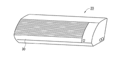
図1は、本実施例における空気調和機用清掃装置を搭載した空気調和機の室内機の斜視図、図2は、同室内機の概略断面図である。 FIG. 1 is a perspective view of an indoor unit of an air conditioner equipped with the air conditioner cleaning device according to the present embodiment, and FIG. 2 is a schematic cross-sectional view of the indoor unit.
図1、2において、30は、本実施例における空気調和機用清掃装置で、室内に設置された空気調和機の室内機20に、前方より着脱自在に装着されると共に、室内機20に内蔵されたエアーフィルター21の表面に付着した塵埃を除去するための回転清掃体34を内蔵している。
1 and 2,
室内機20の前面には、室内の空気を取り入れるための吸込口22aを有する前面パネル22が設けられ、その吸込口22aの下流側に、エアーフィルター21、室内の空気を熱交換する熱交換器23、ファン24が順に配され、ファン24を運転すると、室内の空気が、吸込口22aから吸引され、熱交換器23で熱交換された後、吹出口25から室内に吹き出される。
A
エアーフィルター21は、図2に示すように、ベルト状に形成されると共に、図示しないモーターと減速装置からなる駆動手段26で回転駆動される駆動プーリー27と、従動プーリー28間に張架されている。
As shown in FIG. 2, the
次に、空気調和機用清掃装置30の詳細について図3〜7を用いて説明する。
Next, the detail of the
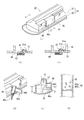
図3は、空気調和機用清掃装置の斜視図、図4は、同空気調和機用清掃装置の分解図、図5は、同空気調和機用清掃装置の塵埃移送手段の構成を示す展開図、図6は、図3のA−A断面図である。 FIG. 3 is a perspective view of the air conditioner cleaning device, FIG. 4 is an exploded view of the air conditioner cleaning device, and FIG. 5 is a development view showing the configuration of the dust transfer means of the air conditioner cleaning device. 6 is a cross-sectional view taken along the line AA in FIG.
図3〜6において、空気調和機用清掃装置30は、カバー上31と、カバー下32からなり、室内機20に着脱自在で、塵埃を収納する集塵ボックス33と、集塵ボックス33に回転自在に、かつ着脱自在に収納された回転清掃体34と、回転清掃体34で掻き取られ集塵ボックス33内に溜まった塵埃を、集塵ボックス33の長手方向に沿って移送させる塵埃移送手段36と、カバー上31の内壁に長手方向に一体に略櫛状に形成され、回転清掃体34に付着した塵埃を掻き取る塵埃除去手段37を備えている。
3 to 6, the air
塵埃移送手段36は、図4、5に示すように、カバー上31の上面をスライド自在のつまみ40と、つまみ40の底面に垂下形成されたリブ40aが挿入嵌合される受け部41aを有する移送板41から構成されている。42は、カバー上31に設けられ、つまみ40のリブ40aをガイドするスリットで、43は、つまみ40のリブ40aが貫通するスリット43aを有すると共に、カバー上31の裏面に貼着されるシール部材で、カバー上31のスリット42から、外気が流入するのを防止するためのものである。
As shown in FIGS. 4 and 5, the dust transfer means 36 has a
又、カバー上31の一側には、内部に溜まった塵埃を排出するための塵埃排出口45と、その塵埃排出口45を開閉する蓋体46が開閉自在に設けられている。この蓋体46の側面には、蓋体46を開ける際に指を引っ掛けるための凹部47が設けられている。なお、蓋体46を、カバー上31に着脱自在に、或いは、開閉自在で、しかもこじると簡単に外れるようにして設けても良い。
In addition, a
次に、回転清掃体34の詳細について、図7を用いて述べる。
Next, details of the
図7(a)は、回転清掃体34及び室内機20の一部の斜視図、(b)は、同回転清掃体34の製法を示す図である。
FIG. 7A is a perspective view of a part of the
図7において、回転清掃体34は、棒状で金属材料からなる軸体51と、軸体51の外周に螺旋状に巻き付けられると共に、基布52aと、基布52aに植毛されたブラシ部52bからなる起毛布52と、軸体51の両側に設けられ軸体51を回転自在に保持すると共に、カバー上31に装着される軸受け体53と、軸体51の一端に固着され、空気調和機用清掃装置30を室内機20の前方より装着したときに、室内機20側に設けられた駆動手段A54で回転駆動されるギアーA55と噛み合うギアーB56とから構成されている。回転清掃体34が、集塵ボックス33に装着された状態では、塵埃除去手段37の先端が回転清掃体34のブラシ部52bに食い込んでいる。
In FIG. 7, the
又、本実施例では、軸体51に巻きつけられた起毛布52の全幅寸法(有効清掃幅寸法L)を500mm以上としている。
In this embodiment, the full width dimension (effective cleaning width dimension L) of the raised
なお、本実施例では、上述のように、軸体51を1本の棒状部材で形成しているが、複数本に分割して、それらを螺子嵌合や、圧入等で繋ぐようにしても良い。そのようにすれば、軸体51の運搬が容易で、しかも梱包形態も簡素化される。
In this embodiment, as described above, the
また、軸体51を、パイプのような中空の部材で形成すれば、軸体51の質量が低減し、回転清掃体34、ひいては、空気調和機用清掃装置30の軽量化を図ることが出来る。
Further, if the
以上のように構成された本実施例における空気調和機用清掃装置30及びそれを搭載した空気調和機の室内機20の動作、作用は以下の通りである。
The operation and action of the air
図1に示すように、予め、空気調和機用清掃装置30を、空気調和機の室内機20の所定に箇所に装着しておく。この状態では、図2及び6に示すように、空気調和機用清掃装置30に内蔵された回転清掃体34のブラシ部52bの先端がエアフィルター21の表面に当接している。
As shown in FIG. 1, an air
又、空気調和機用清掃装置30のつまみ40を操作して、移送板41を、集塵ボックス33の塵埃排出口45と反対側の端部に寄せておく。
Further, the
そして、室内機20を例えば、冷房運転すると、ファン24の運転により室内の空気が吸込口22aから流入し、エアフィルター21を通って熱交換器23に至り、そこで冷却され、冷たい空気が吹出口25から室内に吹き出される。吸込口22aから吸引される室内の空気に含まれた塵埃は、エアフィルター21で捕獲され、そのエアフィルター21の表面に次第に堆積していく。エアフィルター21の表面に塵埃が堆積してくると、空気の通気圧損が増加し、熱交換器23での熱交換効率が低下してくるので、定期的に或いは、必要に応じて、エアフィルター21に堆積した塵埃の除去運転が必要となる。
For example, when the
そこで、本実施例では、塵埃の除去運転を開始すると、図2、図6に示すように、駆動手段26により駆動プーリー27が反時計方向に回転し、エアフィルター21が矢印A方向に移動を開始する。同時に、空気調和機用清掃装置30の回転清掃体34が、同じく反時計方向(矢印B)に回転させることにより、エアフィルター21の表面に付着していた塵埃35が回転清掃体34のブラシ部52bにより掻き取られ、集塵ボックス33内にこぼれ落ちる。同時に、ブラシ部52b上に取り残された塵埃は、櫛状の塵埃除去手段37により、除去される。
Therefore, in this embodiment, when the dust removal operation is started, as shown in FIGS. 2 and 6, the driving
この塵埃除去運転は、ベルト状のエアフィルター21が半周すなわち、エアフィルター21の前側半分が、後ろ側に移動するまで行なわれる。通常、エアフィルター21の後ろ側半分には、塵埃がほとんど堆積しないので、塵埃除去運転を終えた時点で、エアフィルター21のきれいな後ろ側半分が、前側に移動している。
This dust removal operation is performed until the belt-
何度か、上記塵埃除去運転を行なうと、空気調和機用清掃装置30の集塵ボックス33内に塵埃が堆積してくるので、それを廃棄する必要がある。
When the dust removal operation is performed several times, dust accumulates in the
本実施例における塵埃廃棄作業は以下のようにして行なわれる。 The dust disposal work in the present embodiment is performed as follows.
まず、空気調和機用清掃装置30を室内機20から取り外す。次に、つまみ40を操作して、移送板41を塵埃排出口45側に移動させる。この動作により、集塵ボックス33内の塵埃が圧縮されながら、一塊になって、塵埃排出口45側に移動し、最後に、ゴミ箱(図示せず)上で、蓋体46を開けると、塵埃が圧縮されながら、一塊になって自重で、ゴミ箱内に落下し、塵埃廃棄作業を終える。そして、つまみ40を再度操作して、移送板41を塵埃排出口45と反対側に移動させた後、空気調和機用清掃装置30を、室内機20の所定の場所に再度装着する。
First, the air
なお、上記実施例では、集塵ボックス33内の塵埃を廃棄する時に、つまみ40を操作するように説明したが、空気調和機用清掃装置30を室内機20に装着したままの状態で、時々つまみ40を往復操作させて、集塵ボックス33内の塵埃を圧縮して塵埃排出口45側に寄せて置くようにしても良い。こうすれば、より多くの塵埃を集塵ボックス33内に溜めておけるので、塵埃の廃棄頻度が減り、メンテナンスが容易になるものである。
In the above embodiment, the
以上のように、本実施例によれば、回転清掃体34によってエアフイルター21に付着した塵埃35が確実に掻き取られると共に、その塵埃35が集塵ボックス33に収納されるので、塵埃35の廃棄、メンテナンスが容易である。また、塵埃移送手段36で、集塵ボックス33内の塵埃35を一方に移送すると、塵埃35が圧縮されるので、集塵ボックス33内に多量の塵埃35を溜めておけるようになり、集塵ボックス33内の塵埃35の廃棄頻度が減り、塵埃35の廃棄作業が軽減される。又、塵埃35を吸引すると共に外部にそれを排出するための吸引装置などが不要なので、小型、低騒音で、しかも衛生的である。
As described above, according to the present embodiment, the
又、回転清掃体34は、集塵ボックス33内に着脱自在に収納されると共に、前記集塵ボックス33を空気調和機の室内機20に対し着脱自在なので、一般に高所に設置された室内機20から集塵ボックス33を容易に取り外すことができ、集塵ボックス33内の塵埃35の廃棄が容易で、しかも回転清掃体34を集塵ボックス33から容易に取り出せるので、回転清掃体33にこびりついた塵埃35の除去、清掃も容易になる。
Further, the
又、集塵ボックス33に塵埃排出用の塵埃排出口45を設け、その塵埃排出口45を塞ぐ蓋体46を着脱自在または/及び開閉自在に設けたので、集塵ボックス33内に堆積した塵埃35を、塵埃移送手段36で、塵埃排出口45まで移送すると、その間に塵埃が圧縮されると共に、蓋体46を開放すると、圧縮された塵埃35が一箇所の塵埃排出口45から排出されるので、廃棄時に、塵埃35が周囲に飛び散ることが無く、衛生的である。
Further, the
さらに、回転清掃体34に付着した塵埃を除去する塵埃除去手段37を設けたことにより、回転清掃体34を常にきれいに保つことができ、塵埃掻き取り性能が低下することが無く、また、回転清掃体34で掻き取られた塵埃35が、エアフイルター21に再付着することも無く、塵埃除去性能が向上する。
Further, by providing the
又、回転清掃体34を、棒状の軸体51と、軸体51に螺旋状に巻き付けられると共に基布52aと、基布52aに植毛されたブラシ部52bからなる起毛布52とで構成したことにより、回転清掃体34の製造が容易になり、空気調和機用清掃装置30を安価に形成することができる。
Further, the
又、軸体51に巻きつけられた起毛布52の全幅寸法(有効清掃幅寸法)を500mm以上としたことにより、空気調和機の室内機20に内設された幅の広いエアフイルター21の全幅に渡って、ブラシ部52bが当たるので、回転清掃体34を超低速(例えば、10RPM程度)で回転させても十分均一にエアフイルター21を清掃することができ、しかも回転清掃体34の回転時の騒音を低減することができる。
In addition, by setting the overall width dimension (effective cleaning width dimension) of the raised
(実施例2) (Example 2)
図8(a)は、本発明の第2の実施例における空気調和機用清掃装置の部分斜視図、(b)は、図8(a)のB−B断面図、(c)は、図8(a)のB−B断面図(蓋体が開く直前)、(d)は、同蓋体が開いた様子を示す部分斜視図、(e)は、図8(a)のC−C断面図、(f)は、図8(e)のD−D断面図である。なお、上記実施例と同一部分については、同一符号を付してその説明を省略する。 FIG. 8A is a partial perspective view of the air conditioner cleaning device according to the second embodiment of the present invention, FIG. 8B is a sectional view taken along line BB in FIG. 8A, and FIG. FIG. 8A is a cross-sectional view taken along the line B-B (just before the lid is opened), FIG. 8D is a partial perspective view showing a state in which the lid is opened, and FIG. 8E is a cross-sectional view taken along C-C in FIG. Sectional drawing and (f) are DD sectional drawings of FIG.8 (e). In addition, about the same part as the said Example, the same code | symbol is attached | subjected and the description is abbreviate | omitted.
図8において、集塵ボックス33には、塵埃排出口45を開閉する蓋体46の一側が回転自在に軸支され、その蓋体46を常時開く方向に付勢するトーションスプリングなどから成る付勢部材A60が設けられている。蓋体46の他側(軸支された側の反対側)には、左右方向に摺動自在の引っ掛け部材61が設けられている。この引っ掛け部材61は、集塵ボックス33の塵埃排出口45の縁に引っ掛けられる爪部61aが設けられ、蓋体46が閉じられた状態では、引っ掛け部材61の爪部61aが、付勢部材B62の付勢力で、塵埃排出口45の縁側に付勢され、爪部61aが塵埃排出口45の縁に引っ掛けられた状態で維持されるようになっている(図8(b)の状態)。
In FIG. 8, in the
そして、塵埃移送手段36のつまみ40を、塵埃排出口45側に移動させると、つまみ40に連結された移送板41の端部に設けた突起部41aが、引っ掛け部材61の爪部61aに当接し、さらに、つまみ40を、付勢部材B62の付勢力に抗して移動させると、爪部61aが、塵埃排出口45の縁から外れ、同時に、付勢部材A60の付勢力により蓋体46が強制的に開放され、中の塵埃が排出されるようになっている。
When the
また、本実施例では、図8(d)〜(f)に示すように、蓋体46は、前壁46aとそれに対しほぼ直角に形成された横壁46bから構成され、さらに横壁46bの下縁には、蓋体46を開けるときに、カバー下32の底面を掃くための掃き出しブラシ46cが設けられている。同構成により、蓋体46が閉じた状態では、図8(f)に示すように、蓋体46の横壁46bは、集塵ボックス33内で、その長手方向に直交するように配置される。
In this embodiment, as shown in FIGS. 8D to 8F, the
以上のように本実施例によれば、塵埃排出口45を塞ぐ蓋体46を開閉自在に設けると共に、その蓋体46の開動作と塵埃移送手段36の動作を連動させたことにより、集塵ボックス33内に堆積した塵埃35を、塵埃移送手段36で、塵埃排出口45まで移送すると、その間に塵埃35が圧縮されるが、その移送動作に連動して蓋体46が開放するので、一つの移送動作で、塵埃35を一箇所の塵埃排出口45から排出できると共に、塵埃35が圧縮されているので、廃棄時に、塵埃35が周囲に飛び散ることが無く、衛生的である。
As described above, according to the present embodiment, the
又、蓋体46が開くときに、蓋体46の横壁46bが、強制的に集塵ボックス33内の塵埃35の塊を掃き出すので、確実に塵埃35を集塵ボックス33から排出させることが出来る。しかも、横壁46bの下縁に設けた掃き出しブラシ46cにより、蓋体46の背後に位置するカバー下32の底面が、塵埃の廃棄の都度清掃されるので、その部分に塵埃が堆積して中の塵埃の塊が出難くなることが無い。
Further, when the
(実施例3) (Example 3)
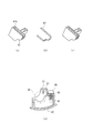
図9(a)は、本発明の第3の実施例における空気調和機用清掃装置の移送板の斜視図、(b)は、同移送板に装着される清掃片の斜視図、(c)は、同移送板に清掃片を組み込んだ状態を示す図、(d)同空気調和機用清掃装置の要部断面図である。なお、上記実施例と同一部分については、同一符号を付してその説明を省略する。 FIG. 9A is a perspective view of a transfer plate of an air conditioner cleaning apparatus according to a third embodiment of the present invention, FIG. 9B is a perspective view of a cleaning piece mounted on the transfer plate, and FIG. These are the figures which show the state which incorporated the cleaning piece in the transfer board, (d) It is principal part sectional drawing of the cleaning apparatus for air conditioners. In addition, about the same part as the said Example, the same code | symbol is attached | subjected and the description is abbreviate | omitted.
本実施例は、図9に示すように、移送板41の、集塵ボックス33の内壁と対向する周縁に凹溝41bを設け、その凹溝41bにブラシ状の清掃片47を装着したもので、これにより、塵埃移送手段36を動作させる都度、集塵ボックス33の内壁が清掃片47で清掃されるので、集塵ボックス33の内壁に汚れが堆積することが無く、非常に衛生的である。
In the present embodiment, as shown in FIG. 9, a
(実施例4) Example 4
図10は、本発明の第4の実施例における空気調和機用清掃装置の部分斜視図である。なお、上記実施例と同一部分については、同一符号を付してその説明を省略する。 FIG. 10 is a partial perspective view of the air conditioner cleaning device according to the fourth embodiment of the present invention. In addition, about the same part as the said Example, the same code | symbol is attached | subjected and the description is abbreviate | omitted.
本実施における空気調和機用清掃装置は、図10に示すように、空気調和機用清掃装置30の内部や外部に付着した塵埃を払うためのお手入れ用のハケ65を備え、そのハケ65を着脱自在に保持するハケ保持部66を、カバー上31の上面に形成したものである。
As shown in FIG. 10, the air conditioner cleaning apparatus in the present embodiment includes a
ハケ65は、持ち部65aと、 持ち部65aの端部に形成され埃を払うハケ部65bから構成されている。
The
本実施例では、以上のように構成されているので、集塵ボックス33内の塵埃を廃棄する都度、回転清掃体34や、集塵ボックス33をハケ65できれいにすることができると共に、そのハケ65の保管が容易で、しかもその保管場所を忘れることも無いので非常に使用勝手の良いものである。
Since the present embodiment is configured as described above, the
なお、上記実施例では、ハケ保持部66を、カバー上31の上面に形成したが、特にその部分に限定するものでは無く、カバー上31の側面や、カバー下32に設けても良い。
In the above embodiment, the
さらに、空気調和機の室内機20に、従来の塵埃掻き取り性能を維持しながら、小型、低騒音で、しかもメンテナンスが容易な上記空気調和機用清掃装置30を用いることにより、エアフイルター21を常にきれいに保つことが出来るので、空調性能に優れ、しかもメンテナンスの容易な空気調和機を提供することが出来る。
Furthermore, by using the air
以上のように、本発明にかかる空気調和機用清掃装置は、従来の塵埃掻き取り性能を維持しながら、小型、低騒音で、しかも衛生的で、また、塵埃の廃棄、メンテナンスが容易なもので、家庭用、業務用の各種空気調和機は勿論、空気清浄機、換気装置などエアフィルターを有する各種機器に適用できるものである。 As described above, the cleaning device for an air conditioner according to the present invention is small, low noise, hygienic, and easy to dispose and maintain dust while maintaining the conventional dust scraping performance. Thus, it can be applied not only to various air conditioners for home use and business use, but also to various devices having an air filter such as an air purifier and a ventilator.
20 室内機(空気調和機)
21 エアフィルター
23 熱交換器
24 ファン
25 吹出口
30 空気調和機用清掃装置
33 集塵ボックス
34 回転清掃体
35 塵埃
36 塵埃移送手段
37 塵埃除去手段
40 つまみ
41 移送板
45 塵埃排出口
46 蓋体
65 ハケ
66 ハケ保持部
20 Indoor unit (air conditioner)
21
Claims (8)
Priority Applications (1)
| Application Number | Priority Date | Filing Date | Title |
|---|---|---|---|
| JP2006237921A JP4896636B2 (en) | 2006-09-01 | 2006-09-01 | Air conditioner cleaning device and air conditioner |
Applications Claiming Priority (1)
| Application Number | Priority Date | Filing Date | Title |
|---|---|---|---|
| JP2006237921A JP4896636B2 (en) | 2006-09-01 | 2006-09-01 | Air conditioner cleaning device and air conditioner |
Publications (3)
| Publication Number | Publication Date |
|---|---|
| JP2008057923A JP2008057923A (en) | 2008-03-13 |
| JP2008057923A5 JP2008057923A5 (en) | 2009-10-08 |
| JP4896636B2 true JP4896636B2 (en) | 2012-03-14 |
Family
ID=39240871
Family Applications (1)
| Application Number | Title | Priority Date | Filing Date |
|---|---|---|---|
| JP2006237921A Active JP4896636B2 (en) | 2006-09-01 | 2006-09-01 | Air conditioner cleaning device and air conditioner |
Country Status (1)
| Country | Link |
|---|---|
| JP (1) | JP4896636B2 (en) |
Families Citing this family (13)
| Publication number | Priority date | Publication date | Assignee | Title |
|---|---|---|---|---|
| JP4980752B2 (en) * | 2007-03-02 | 2012-07-18 | 株式会社コーワ | Air conditioner cleaning device and air conditioner |
| JP2009228932A (en) * | 2008-03-19 | 2009-10-08 | Kowa Co Ltd | Air conditioner |
| JP2010043781A (en) * | 2008-08-12 | 2010-02-25 | Sanyo Electric Co Ltd | Air conditioner |
| CN103727648B (en) * | 2008-09-09 | 2017-04-12 | 大金工业株式会社 | Filter cleaning unit and air conditioner |
| JP5020200B2 (en) * | 2008-09-09 | 2012-09-05 | 三菱電機株式会社 | Filter cleaning device and air conditioner equipped with the same |
| JP2011012936A (en) * | 2009-07-06 | 2011-01-20 | Hitachi Appliances Inc | Ceiling embedded type air conditioner |
| JP5388901B2 (en) | 2010-03-01 | 2014-01-15 | 三菱電機株式会社 | Projection-type image display device |
| JP7361296B2 (en) * | 2019-07-02 | 2023-10-16 | パナソニックIpマネジメント株式会社 | air conditioner |
| JP7361295B2 (en) | 2019-07-02 | 2023-10-16 | パナソニックIpマネジメント株式会社 | air conditioner |
| JP7316491B2 (en) * | 2019-07-29 | 2023-07-28 | パナソニックIpマネジメント株式会社 | air conditioner |
| JP7369906B2 (en) * | 2019-08-07 | 2023-10-27 | パナソニックIpマネジメント株式会社 | air conditioner |
| JP7285398B2 (en) * | 2019-08-22 | 2023-06-02 | パナソニックIpマネジメント株式会社 | air conditioner |
| CN112914292A (en) * | 2021-01-25 | 2021-06-08 | 佛山市高尔顿家具有限公司 | Adjustable health intelligent bed with function of mutual entertainment system |
Family Cites Families (9)
| Publication number | Priority date | Publication date | Assignee | Title |
|---|---|---|---|---|
| JPS5614551A (en) * | 1979-07-16 | 1981-02-12 | Sumika Color Kk | Stabilizing method of polyurethane |
| JPS57121248A (en) * | 1981-01-21 | 1982-07-28 | Hitachi Ltd | Semiconductor device and its manufacture |
| JPS62145019A (en) * | 1985-12-19 | 1987-06-29 | Senjiyu Seiyaku Kk | Anti-inflammatory agent |
| JPH0411328A (en) * | 1990-04-27 | 1992-01-16 | Sanyo Electric Co Ltd | Optical head device |
| JP2002250537A (en) * | 2002-02-26 | 2002-09-06 | Hitachi Ltd | Air conditioner |
| JP4110375B2 (en) * | 2002-06-27 | 2008-07-02 | 株式会社富士通ゼネラル | Air conditioner |
| JP3940052B2 (en) * | 2002-09-10 | 2007-07-04 | 三菱電機株式会社 | Vacuum cleaner and method for cleaning a vacuum cleaner |
| JP4154574B2 (en) * | 2002-09-25 | 2008-09-24 | 株式会社富士通ゼネラル | Air conditioner |
| JP2004121795A (en) * | 2002-10-02 | 2004-04-22 | Kowa Co Ltd | Rotary rotor for floor nozzle of vacuum cleaner |
-
2006
- 2006-09-01 JP JP2006237921A patent/JP4896636B2/en active Active
Also Published As
| Publication number | Publication date |
|---|---|
| JP2008057923A (en) | 2008-03-13 |
Similar Documents
| Publication | Publication Date | Title |
|---|---|---|
| JP4896636B2 (en) | Air conditioner cleaning device and air conditioner | |
| JP4781956B2 (en) | Air conditioner cleaning device and air conditioner | |
| JP4182328B2 (en) | Air conditioner | |
| JP4980752B2 (en) | Air conditioner cleaning device and air conditioner | |
| JP2006071121A (en) | Air-conditioner | |
| JP5294440B2 (en) | Air conditioner | |
| JP2004301363A (en) | Air conditioner | |
| JP2008128532A (en) | Cleaning device for air conditioner, and air conditioner | |
| CN100385175C (en) | Air conditioner having indoor unit with automatic air filter-cleaning function | |
| JP2010249358A (en) | Indoor unit for air conditioner | |
| JP2008029912A (en) | Cleaning device for filter | |
| JP2004156794A (en) | Air conditioner | |
| JP5755088B2 (en) | Air conditioner indoor unit | |
| JP4125340B2 (en) | Air conditioner cleaning device and air conditioner | |
| JP5503953B2 (en) | Air conditioner indoor unit | |
| JPWO2008062876A1 (en) | Air conditioner indoor unit | |
| JP4269141B2 (en) | Air conditioner | |
| JP2008111590A (en) | Cleaning apparatus for air conditioner and air conditioner | |
| JP2008128625A (en) | Cleaning device for air conditioner, and air conditioner | |
| JP2008039324A (en) | Indoor unit of air conditioner | |
| WO2021002201A1 (en) | Air conditioner | |
| JP6767635B2 (en) | Air conditioner | |
| JP2009257735A (en) | Air conditioner | |
| JP2006118737A (en) | Filter device for air conditioner | |
| JP2008032249A (en) | Cleaning device for filter |
Legal Events
| Date | Code | Title | Description |
|---|---|---|---|
| A521 | Request for written amendment filed |
Free format text: JAPANESE INTERMEDIATE CODE: A523 Effective date: 20090826 |
|
| A621 | Written request for application examination |
Free format text: JAPANESE INTERMEDIATE CODE: A621 Effective date: 20090826 |
|
| RD02 | Notification of acceptance of power of attorney |
Free format text: JAPANESE INTERMEDIATE CODE: A7422 Effective date: 20090826 |
|
| A977 | Report on retrieval |
Free format text: JAPANESE INTERMEDIATE CODE: A971007 Effective date: 20110610 |
|
| A131 | Notification of reasons for refusal |
Free format text: JAPANESE INTERMEDIATE CODE: A131 Effective date: 20110616 |
|
| A521 | Request for written amendment filed |
Free format text: JAPANESE INTERMEDIATE CODE: A523 Effective date: 20110811 |
|
| TRDD | Decision of grant or rejection written | ||
| A01 | Written decision to grant a patent or to grant a registration (utility model) |
Free format text: JAPANESE INTERMEDIATE CODE: A01 Effective date: 20111125 |
|
| A01 | Written decision to grant a patent or to grant a registration (utility model) |
Free format text: JAPANESE INTERMEDIATE CODE: A01 |
|
| A61 | First payment of annual fees (during grant procedure) |
Free format text: JAPANESE INTERMEDIATE CODE: A61 Effective date: 20111221 |
|
| R150 | Certificate of patent or registration of utility model |
Free format text: JAPANESE INTERMEDIATE CODE: R150 Ref document number: 4896636 Country of ref document: JP Free format text: JAPANESE INTERMEDIATE CODE: R150 |
|
| FPAY | Renewal fee payment (event date is renewal date of database) |
Free format text: PAYMENT UNTIL: 20150106 Year of fee payment: 3 |
|
| R250 | Receipt of annual fees |
Free format text: JAPANESE INTERMEDIATE CODE: R250 |
|
| R250 | Receipt of annual fees |
Free format text: JAPANESE INTERMEDIATE CODE: R250 |
|
| R250 | Receipt of annual fees |
Free format text: JAPANESE INTERMEDIATE CODE: R250 |
|
| R250 | Receipt of annual fees |
Free format text: JAPANESE INTERMEDIATE CODE: R250 |