JP3940052B2 - Vacuum cleaner and method for cleaning a vacuum cleaner - Google Patents
Vacuum cleaner and method for cleaning a vacuum cleaner Download PDFInfo
- Publication number
- JP3940052B2 JP3940052B2 JP2002263507A JP2002263507A JP3940052B2 JP 3940052 B2 JP3940052 B2 JP 3940052B2 JP 2002263507 A JP2002263507 A JP 2002263507A JP 2002263507 A JP2002263507 A JP 2002263507A JP 3940052 B2 JP3940052 B2 JP 3940052B2
- Authority
- JP
- Japan
- Prior art keywords
- dust
- vacuum cleaner
- opening
- cyclone dust
- cyclone
- Prior art date
- Legal status (The legal status is an assumption and is not a legal conclusion. Google has not performed a legal analysis and makes no representation as to the accuracy of the status listed.)
- Expired - Fee Related
Links
Images


Description
【0001】
【発明の属する技術分野】
この発明は清掃気流から遠心力によって塵埃等を分離するサイクロン式電気掃除機および電気掃除機を清掃する方法に関するものである。
【0002】
【従来の技術】
従来のサイクロン式電気掃除機は、掃除機本体とは別部材で構成されるサイクロン集塵カップを備え、清掃気流をサイクロン集塵カップ内で回転させてその遠心力によって塵埃をサイクロン集塵カップ内に貯留する。
【0003】
サイクロン集塵カップは掃除機本体上の保持部に着脱自在に保持され、下ケースと上ケースを係合させることにより掃除機本体に固定される。
【0004】
サイクロン集塵カップでろ過し切れなかった塵埃の電動送風機125への流出を防止するため、排出口はメッシュネット135によって覆われている。
【0005】
このような構成の電気掃除機を運転することで、被清掃面より吸引された塵埃が清掃気流の遠心力と、重力によりサイクロン集塵カップ内部に貯留されて、清掃が実行される。
【0006】
サイクロン集塵カップ内部に貯留された塵埃の廃棄は、上ケースの下ケースへの係合を解除し、サイクロン集塵カップを保持部より取り外して行う。(例えば、特許文献1参照。)
【0007】
【特許文献1】
特開2002−17623(第3−6頁、図1、2、5、7、8)
【0008】
【発明が解決しようとする課題】
しかしながら、従来のサイクロン式電気掃除機はサイクロン集塵カップを取り外して内部に貯留した塵埃を廃棄しても、細かい塵埃がカップに付着して残ってしまい、また、メッシュネットに絡みついた髪の毛や綿埃はカップを叩く程度では除去できなかった。したがって、この細かい塵埃を除去するためには、別途用意したブラシや布等で掃き落とすか水洗いをしなければならず、作業が煩わしかった。
【0009】
この発明は、上記課題に鑑みてなされたもので、電気掃除機の集塵部に貯留された塵埃を廃棄した際に集塵部に付着して残る細かい塵埃やフィルタ部に絡みついた髪の毛や綿埃を容易かつ清潔に除去することが可能な電気掃除機および電気掃除機を清掃する方法を提供することを目的とする。
【0010】
【課題を解決するための手段】
清掃気流を発生させる電動送風機を有した掃除機本体と、該電動送風機により発生した前記清掃気流に含まれる塵埃を分離し、開口を介して塵埃を排出するサイクロン集塵装置と、前記本体および前記サイクロン集塵装置の少なくとも一方に着脱自在に設けられ、前記サイクロン集塵装置の動作時に前記サイクロン集塵装置から排出された塵埃を取り込んで貯留する集塵箱と、を備えた電気掃除機において、前記集塵箱を取り外した時に、前記サイクロン集塵装置の開口を閉塞可能な閉塞部材を有し、前記閉塞部材により前記開口を閉塞して前記電動送風機を動作させることにより、前記サイクロン集塵装置内を負圧にするものである。
【0011】
また、前記集塵箱を取り外し、前記閉塞部材で前記サイクロン集塵装置の開口を閉じた状態で、掃除機本体を動作させて前記集塵箱に付着した塵埃を吸引してもよい。
【0012】
また、前記集塵箱を取り外して掃除機本体を動作させる際に、前記閉塞部材で前記サイクロン集塵装置の開口を閉じることを促す表示部を有していてもよい。
【0013】
また、前記集塵箱が、前記サイクロン集塵装置の開口と連通する連通口を有するとともに、該連通口の周囲の少なくとも一部の集塵箱壁面が外方に突出することにより形成された突出部を有し、掃除機本体に取りつけられた時に該突出部の先端が前記サイクロン集塵装置の内壁面と同一面上に位置していてもよい。
【0014】
また、前記掃除機本体が、前記閉塞部材を収納する収納部を備えていてもよい。
【0015】
また、前記サイクロン集塵装置が、前記閉塞部材を収納する収納部を備えていてもよい。
【0016】
清掃気流を発生させる電動送風機を有した掃除機本体と、該電動送風機により発生した前記清掃気流に含まれる塵埃を分離し、開口を介して塵埃を排出するサイクロン集塵装置と、前記本体および前記サイクロン集塵装置の少なくとも一方に着脱自在に設けられ、前記サイクロン集塵装置の動作時に前記サイクロン集塵装置から排出された塵埃を取り込んで貯留する集塵箱と、前記サイクロン集塵装置の開口を閉塞可能な閉塞部材とを有し、前記閉塞部材により前記開口を閉塞して前記電動送風機を動作させることにより、前記サイクロン集塵装置内を負圧にする電気掃除機を清掃する方法において、集塵箱を取り外すステップと閉塞部材でサイクロン集塵装置の開口を閉じるステップと、掃除機本体を動作させて塵埃を吸引するステップと、閉塞部材を取り外してサイクロン集塵装置の開口を開けるステップと、集塵箱を取り付けるステップと、を有する電気掃除機を清掃する方法。
【0017】
【発明の実施の形態】
発明の実施の形態1.
図1に、本発明の実施の形態1に係る電気掃除機1の外観図、図2にこの電気掃除機に取り付けられる塵埃吸引具10の外観図を示す。
【0018】
図1に示すように電気掃除機1は、前部にホース接続口21を有し側部に移動用車輪22を備えた掃除機本体2と、ホース接続口21を介して流入する清掃気流に含まれる塵埃を遠心力を利用して分離するサイクロン集塵装置3と、サイクロン集塵装置3により分離された塵埃を取り込んで貯留する本体2とサイクロン集塵装置3の少なくとも一方に対して着脱自在の集塵箱4を備えている。また、掃除機本体2は、その上部に装着された集塵箱4を本体から取り外す際に利用するポップアップレバー6をその外側面に有している。
【0019】
ホース接続口21には、図2に示すような塵埃吸引具10が取り付けられる。この塵埃吸引具10は、一端をホース接続口21に接続する蛇腹を有するホース11、ホース11の他端に取り付けられるハンドル部12、ハンドル部12と接続するパイプ材13、14、パイプ材14の終端が接続し、被清掃面から塵埃を吸引するための床ブラシ15により構成される。
【0020】
図3にサイクロン集塵装置3の円筒軸方向断面図を示す。
図3に示すように、サイクロン室本体32の円周部下部には掃除機本体2の気流導入路23からサイクロン室本体32の内部に塵埃を含む清掃気流を導入する気流導入口345が設けられている。さらに、サイクロン室本体32の円周部下部には気流導入口345と隔壁を隔ててキャップ34の排気口344と連なる排気風路346が設けられている。
【0021】
このように構成されたサイクロン集塵装置3は、気流導入口345から塵埃を含む清掃気流をサイクロン室本体32の内部に導入して内部に渦流を発生させ、この過流による遠心力で清掃気流から塵埃を集塵箱4に放出させるとともに、塵埃がろ過された清掃気流は気流導出口342からキャップ34内部を通って、排気口344より排気風路346へ流れるようになっている。
【0022】
図4において電気掃除機1全体の内部構造を断面図にて示す。
電動送風機24が回転して発生する清掃気流が塵埃吸引具10から接続口21、気流導入路23を経由してサイクロン集塵装置3に導かれる。サイクロン集塵装置3では、気流導入口345から塵埃を含む清掃気流を導入し、渦流を発生させ、この渦流による遠心力で清掃気流から塵埃を分離して開口326から集塵箱4に向けて放出させるとともに、塵埃がろ過された清掃気流は排気風路346へ流れ、ろ過しきれなかった細かい塵埃を捕集する着脱自在に設けられた塵埃捕集フィルタ51を通って送風機に向かい、排気される。
【0023】
サイクロン集塵装置3の後方に、集塵箱4が蓋41をサイクロン集塵装置側に向けて配置されており、その蓋41にはサイクロン集塵装置3の開口326と連通する連通口411が形成されている。そして、連通口411の下辺がサイクロン集塵装置側に突出した突出部412となっていて、集塵箱4が掃除機本体2に取りつけられている時にこの突出部412はサイクロン集塵装置3の開口326の小口下辺に沿うとともに、その先端はサイクロン集塵装置の内壁面と同一面上に来るように設定されている。尚、図3中の矢印は清掃気流の流れる方向を示している。
【0024】
図5に掃除機1を図1の状態から集塵箱4を取り外した状態としたときの外観図を示す。
集塵箱4が装着される凹部25の底面にバネやゴム等の弾性体の弾性力を利用して集塵箱4を上方向に付勢する弾性機構9が配置されている。凹部25の縁部には、ポップアップレバー6のスライド(矢印A方向)に連動してスライドする(矢印B方向)集塵箱保持爪27が設置されている。この集塵箱保持爪27は集塵箱4に設けられるロック爪47と係合して集塵箱4を掃除機本体2に固定する。集塵箱4の後端には、凹部25の後部壁面に形成された溝26に着脱自在に係合する突起42が設けられている。
【0025】
図6に集塵箱保持爪27、ロック爪47の係合作用図を示す。図6に示すように集塵箱保持爪27は本体2の凹部25に形成された空間部28内にスライド可能に配置されている。集塵箱保持爪27がポップアップレバー6の動さに連動して矢印C方向にスライドすると、集塵箱4のロック爪47との係合が解除される。
【0026】
図7に、集塵箱4の構造を示す斜視図を示す。
図7に示すように集塵箱4は、サイクロン集塵装置3との連通部側が塵埃捨て口45として開口する箱体である。塵埃捨て口45近傍の左右側に前述したロック爪47が、塵埃捨て口45と反対側の端部に突起42がそれぞれ形成されており、これらにより掃除機本体2への連結を実現する。
【0027】
塵埃捨て口45は、軸481と軸支持片431とを利用して塵埃捨て口45の底面43に回動自在に取り付けられた蓋41によって開閉される。
ここで、塵埃捨て口45が蓋41で閉じられるとき、蓋41の周囲パッキン413のリップ413aが、塵埃捨て口45の周縁に形成されたシールリブ45aに当接するようになっている。
【0028】
また,集塵箱4のサイクロン集塵装置3との対向面となる蓋41、あるいは蓋41およびフード部49はサイクロン集塵装置3の外周形状に沿って、集塵箱4の底面43から上面44に向かってオーバ−ハングする斜面を形成し、さらに必要に応じてこれらの斜面を利用してサイクロン集塵装置の一部を横または斜め上方から押圧する構造としている。これにより、集塵箱を固定することでサイクロン習字装置3も同時に固定することができ、集塵箱4をサイクロン集塵装置3により妨害されることなく取り外すことができる。
【0029】
蓋41には、サイクロン集塵装置3から放出される塵埃を取りこむため、集塵箱を取りつけた時にサイクロン集塵装置3の開口326に連通する連通口411が設けられている。連通口411の下辺は開口326の小口の下辺に沿って突出した突出部412となっており、その先端はサイクロン集塵装置3の内壁面の径に等しい位置になるように設置されている。これにより、集塵箱4とサイクロン集塵装置3の連結部での段差等による渦流の乱れを防ぐとともに塵埃の漏れを低減することができる。
【0030】
図8にサイクロン集塵装置3の分解斜視図を示す。
図8に示すようにサイクロン集塵装置3は、略円筒形状で一端321が開口し、他端322が閉塞したサイクロン室本体32と、サイクロン室本体32の閉塞端面322に取り付け固定されるカバー33と、サイクロン室本体32の開口端面321に脱着自在に取り付けられるキャップ34とから構成されている。
【0031】
キャップ清掃用ブラシ323は、サイクロン室本体32の開口端面321または端面の近傍に設けられている。メッシュネット341に付着した塵埃や絡みついた髪の毛等を除去する際に、一方の手でサイクロン室本体32を保持し、他方の手でキャップ34を取り外して使用する。このとき、両方の手が塞がった状態のままメッシュネット341を清掃することができるため、清掃の手間が省けるとともに塵埃や髪の毛等に触れずに除去することが出来る。
【0032】
キャップ34はサイクロン室本体32において、遠心力によって塵埃がろ過された清掃気流を外部に導出するためのメッシュネット341が設けられた気流導出口342を有している。また、キャップ34のサイクロン室本体32の開口端面321との接触部分にはパッキン343が設けられており、サイクロン室本体32にキャップ34を取り付けた際に気密を良好に保つようになっている。さらにキャップ34の内部は中空になっており、気流導出口342からキャップ34の内部に流入した気流はキャップ34の下部に設けられた排気口344からキャップ34の外側に排出される。
【0033】
閉塞部材324は、掃除機本体2から集塵箱4を取り外した際に露出するサイクロン集塵装置3の開口326を閉塞するための部材であり、樹脂性または弾性のある硬質ゴム等の材料であればよく、サイクロン集塵装置3に開けられた開口326に隣接して設けられた一対のガイド325によって横方向にスライド可能に保持されている。
【0034】
図9は、閉塞部材324を開口326を閉塞する位置までスライドさせて開口326を閉塞している状態を示している。
閉塞部材324の表面には、集塵箱4を取り外した状態で掃除機を運転する際に開口326を閉塞することを促す文章を表示しておく。
【0035】
この電気掃除機1を使用して部屋の掃除を行うと吸引された塵埃が集塵箱4に貯留される。掃除後にこの溜まった塵埃を廃棄するには、電気掃除機1を停止させた後、集塵箱4を掃除機本体2から取り外し、取っ手46を握った状態で蓋開閉レバー48を引いて蓋41を開け、集塵箱4を傾斜させる。これにより、塵埃は集塵箱より排出される。しかし、細かい塵埃が大量に貯留された場合はきれいに廃棄しきれず、集塵箱4の内部や縁、蓋にも付着して残ってしまう。
【0036】
そこで、この集塵箱4に付着した残留塵埃を、塵埃吸引具10で吸引する。塵埃吸引具10は床ブラシ15を外し、必要あればパイプ材14も外して短くし、パイプ材13の先端で吸引するようにしてもよい。
【0037】
集塵箱4は掃除機本体から取り外されているので、サイクロン集塵装置3において、開口326を閉塞部材324で閉塞する。この状態で電気掃除機1を運転すると、集塵箱4がなくても気流導入口345からサイクロン室本体32内部に空気を導入することが可能となり、サイクロン室本体32内部に渦流が発生する。このとき、サイクロン室本体32内の気圧は電動送風機24の吸引によって負圧になるため、閉塞部材324は開口326に密着する。
【0038】
このようにして、パイプ材13の先端を使用して清掃気流で、集塵箱4の内部や縁、蓋に付着した塵埃を吸引するので、操作者が手を汚すことなく集塵箱4を清潔に保つことが出来る電気掃除機を得ることができる。
【0039】
このとき、サイクロン室本体32が塵埃の貯留部となるが、電気掃除機を停止後、閉塞部材324を開口326から取り去り、集塵箱4を取りつけ再度運転することによりサイクロン室本体32内の塵埃は集塵箱4に貯留される。
【0040】
また、前述したように集塵箱4を取り外した状態で運転されるとき、サイクロン室本体32内は負圧になるので、閉塞部材326の開口324に対する密閉度は高い必要はなく、多少の漏れは許容される。
【0041】
また、集塵箱4の連通口411の下辺は、サイクロン集塵装置3に取り付けた際にサイクロン集塵装置3の内壁面の径に等しい位置まで突出させているので、サイクロン集塵装置3の開口326を閉塞部材324で閉塞している状態で集塵箱4をサイクロン集塵装置3に取り付けようとすると、この突出部が閉塞部材324に当るため集塵箱4が取り付けられないようになっている。したがって、閉塞部材324で開口326を閉じたまま集塵箱4を取り付けてしまうという誤使用の心配はない。
【0042】
以上述べたように、本発明によれば掃除機本体と、サイクロン集塵装置と、集塵箱とを備えた電機掃除機において、集塵箱を取り外した時に、閉塞部材でサイクロン集塵装置の開口を閉塞した状態で掃除機本体を動作させて集塵箱に付着した塵埃を吸引するようにしたので、操作者が手を汚すことなく集塵箱4を清潔に保つことが出来る電気掃除機を得ることができる。
【0043】
また、集塵箱を取り外して掃除機本体を動作させる際に、前記閉塞部材で前記サイクロン集塵装置の開口を閉じることを促す表示部を有するようにすることで操作者に閉塞部材を動かして開口を閉じることを忘れないよう注意を喚起することができる。
【0044】
集塵箱が、連通口の周囲の少なくとも一部の集塵箱壁面が外方に突出することにより形成された突出部を有し、掃除機本体に取りつけられた時に該突出部の先端が前記サイクロン集塵装置の内壁面と同一面上に位置するようにしたので、段差等による渦流の乱れを防ぐとともに塵埃の漏れを低減することができる。
【0045】
また、掃除機本体が前記閉塞部材を収納する収納部を備えているようにしたので、塵埃廃棄作業時に容易に開口を閉塞することが出来るとともに、閉塞部材の紛失を防止できる使い勝手のよい電気掃除機を得ることができる。
【0046】
また、サイクロン集塵装置が前記閉塞部材を収納する収納部を備えているようにしたので、塵埃廃棄作業時に容易に開口を閉塞することが出来るとともに、閉塞部材の紛失を防止できる使い勝手のよい電気掃除機を得ることができる。
【0047】
また、サイクロン室本体の開口端近傍に固定された塵埃除去ブラシを備えるようにしたので、両手が塞がったままでもメッシュネットの清掃ができ、清掃の手間が省けるとともに操作者が手を汚すことなく作業ができる。
【0048】
発明の実施の形態2.
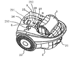
図10に本発明の実施の形態2に係る電気掃除機の外観図を示す。図10においては、掃除機本体2から集塵箱4を取り外した状態を示している。尚、実施の形態1と同一部分には同一番号を付し説明を省略する。
【0049】
図10において、閉塞部材収納部291が掃除機本体2上の集塵箱4が載置される凹部25にさらに凹部を形成することによって作られている。この中に閉塞部材324を収納するようにしている。
同様に凹部25にさらに凹部を形成することによって塵埃除去ブラシ292を収納する凹部293を形成する。
【0050】
これにより、塵埃廃棄時にこの塵埃除去ブラシが使用でき、使用者は手を汚すことがなく集塵箱4清掃ができるとともに、閉塞部材324と塵埃除去ブラシ292が集塵箱4が上に取り付けられることで外観に露出することがないので、外観の印象を損なうことがなくなる。
【0051】
発明の実施の形態3.
図11に本発明の実施の形態3に係る集塵箱4の分解斜視図を示す。
集塵箱4下部にフック435を設け、このフック435に塵埃除去ブラシ292を保持させるようにしている。これにより、塵埃廃棄時にこの塵埃除去ブラシが使用でき、使用者は手を汚すことがなく集塵箱4の清掃ができるとともに塵埃除去ブラシ292が外観に露出することがないので、外観の印象を損なうことがなくなる。
【0052】
【発明の効果】
本発明によれば掃除機本体と、サイクロン集塵装置と、集塵箱とを備えた電機掃除機において、集塵箱を取り外した時に、閉塞部材でサイクロン集塵装置の開口を閉塞した状態で掃除機本体を動作させて集塵箱に付着した塵埃を吸引するようにしたので、操作者が手を汚すことなく集塵箱を清潔に保つことが出来る電気掃除機を得ることができる。
【図面の簡単な説明】
【図1】 本発明の実施の形態1に係る電気掃除機の外観図。
【図2】 本発明の実施の形態1に係る電気掃除機に取り付けられる塵埃吸引具の外観図。
【図3】 本発明の実施の形態1に係るサイクロン集塵装置の円筒軸方向断面図。
【図4】 本発明の実施の形態1に係る電気掃除機の内部構造を示す断面図。
【図5】 本発明の実施の形態1に係る電気掃除機から集塵箱を取り外した状態を示す外観図。
【図6】 本発明の実施の形態1に係る集塵箱保持爪と集塵箱のロック爪との係合作用説明図。
【図7】 本発明の実施の形態1に係る集塵箱の分解斜視図。
【図8】 本発明の実施の形態1に係るサイクロン集塵装置の分解斜視図。
【図9】 本発明の実施の形態1に係るサイクロン集塵装置の分解斜視図。
【図10】 本発明の実施の形態2に係る電気掃除機から集塵箱を取り外した状態を示す外観図。
【図11】 本発明の実施の形態3に係る集塵箱の分解斜視図。[0001]
BACKGROUND OF THE INVENTION
The present invention relates to a cyclonic vacuum cleaner that separates dust and the like from a cleaning airflow by centrifugal force, and a method for cleaning the vacuum cleaner.
[0002]
[Prior art]
The conventional cyclone type vacuum cleaner has a cyclone dust collection cup that is a separate member from the main body of the vacuum cleaner, and the cleaning airflow is rotated in the cyclone dust collection cup, and the centrifugal force causes the dust to enter the cyclone dust collection cup. Store in.
[0003]
The cyclone dust collecting cup is detachably held by a holding portion on the cleaner body, and is fixed to the cleaner body by engaging the lower case with the upper case.
[0004]
In order to prevent the dust that has not been completely filtered by the cyclone dust collecting cup from flowing out to the electric blower 125, the discharge port is covered with a mesh net 135.
[0005]
By operating the electric vacuum cleaner having such a configuration, the dust sucked from the surface to be cleaned is stored in the cyclone dust collection cup by the centrifugal force of the cleaning airflow and the gravity, and cleaning is executed.
[0006]
The dust stored in the cyclone dust collection cup is discarded by disengaging the upper case from the lower case and removing the cyclone dust collection cup from the holding part. (For example, refer to Patent Document 1.)
[0007]
[Patent Document 1]
JP 2002-17623 (page 3-6, FIGS. 1, 2, 5, 7, and 8)
[0008]
[Problems to be solved by the invention]
However, even if the conventional cyclone vacuum cleaner removes the cyclone dust collecting cup and discards the dust stored inside, the fine dust remains attached to the cup, and the hair and cotton entangled with the mesh net Dust could not be removed by hitting the cup. Therefore, in order to remove this fine dust, it has to be swept off with a separately prepared brush or cloth or washed with water, which is cumbersome.
[0009]
The present invention has been made in view of the above problems, and when the dust stored in the dust collection portion of the vacuum cleaner is discarded, the fine dust remaining on the dust collection portion and the hair or cotton entangled with the filter portion An object of the present invention is to provide a vacuum cleaner capable of easily and cleanly removing dust and a method of cleaning the vacuum cleaner.
[0010]
[Means for Solving the Problems]
A vacuum cleaner main body having an electric blower for generating a cleaning airflow, a cyclone dust collecting device for separating dust contained in the cleaning airflow generated by the electric blower and discharging the dust through an opening, the main body and the In a vacuum cleaner comprising: a dust collection box that is detachably provided on at least one of the cyclone dust collector, and that takes in and stores the dust discharged from the cyclone dust collector during operation of the cyclone dust collector; The cyclone dust collector has a closing member capable of closing the opening of the cyclone dust collector when the dust collection box is removed, and the electric blower is operated by closing the opening with the closing member. The inside is a negative pressure .
[0011]
Further, the dust collection box may be removed, and the vacuum cleaner main body may be operated to suck dust attached to the dust collection box with the closing member closing the opening of the cyclone dust collection device.
[0012]
Moreover, when removing the said dust collection box and operating a cleaner main body, you may have a display part which prompts closing the opening of the said cyclone dust collector with the said closure member.
[0013]
In addition, the dust collection box has a communication port communicating with the opening of the cyclone dust collector, and at least a part of the dust collection wall surface around the communication port protrudes outward. And the tip of the protrusion may be located on the same plane as the inner wall surface of the cyclone dust collector when attached to the cleaner body.
[0014]
Moreover, the said vacuum cleaner main body may be provided with the accommodating part which accommodates the said obstruction | occlusion member.
[0015]
The cyclone dust collector may include a storage unit that stores the blocking member.
[0016]
A vacuum cleaner main body having an electric blower for generating a cleaning airflow, a cyclone dust collecting device for separating dust contained in the cleaning airflow generated by the electric blower and discharging the dust through an opening, the main body and the A dust collection box that is detachably provided on at least one of the cyclone dust collectors, and that takes in and stores the dust discharged from the cyclone dust collectors during operation of the cyclone dust collector, and an opening of the cyclone dust collector In a method for cleaning an electric vacuum cleaner having a negative pressure inside the cyclone dust collecting device by closing the opening with the closing member and operating the electric blower. A step of removing the dust box, a step of closing the opening of the cyclone dust collector with the closing member, a step of operating the vacuum cleaner main body to suck the dust, How to clean the steps of opening the opening of the cyclone dust collecting apparatus by removing the closure member, and attaching the dirt container, a vacuum cleaner having a.
[0017]
DETAILED DESCRIPTION OF THE INVENTION
Embodiment 1 of the Invention
FIG. 1 shows an external view of a vacuum cleaner 1 according to Embodiment 1 of the present invention, and FIG. 2 shows an external view of a
[0018]
As shown in FIG. 1, the electric vacuum cleaner 1 has a
[0019]
A
[0020]
FIG. 3 shows a cross-sectional view of the cyclone dust collector 3 in the cylindrical axis direction.
As shown in FIG. 3, an
[0021]
The cyclone dust collecting device 3 configured as described above introduces a cleaning airflow containing dust from the
[0022]
In FIG. 4, the internal structure of the whole vacuum cleaner 1 is shown with sectional drawing.
The cleaning airflow generated by the rotation of the
[0023]
A dust collection box 4 is disposed behind the cyclone dust collector 3 with a
[0024]
FIG. 5 shows an external view of the vacuum cleaner 1 when the dust collection box 4 is removed from the state shown in FIG.
An
[0025]
FIG. 6 shows an engagement operation diagram of the dust
[0026]
FIG. 7 is a perspective view showing the structure of the dust collection box 4.
As shown in FIG. 7, the dust collection box 4 is a box body that opens as a
[0027]
The
Here, when the
[0028]
Further, the
[0029]
The
[0030]
FIG. 8 shows an exploded perspective view of the cyclone dust collector 3.
As shown in FIG. 8, the cyclone dust collecting device 3 has a substantially cylindrical shape with one
[0031]
The
[0032]
In the cyclone chamber
[0033]
The closing
[0034]
FIG. 9 shows a state where the
On the surface of the closing
[0035]
When the vacuum cleaner 1 is used to clean the room, the sucked dust is stored in the dust collection box 4. To discard the accumulated dust after cleaning, after the vacuum cleaner 1 is stopped, the dust collection box 4 is detached from the vacuum cleaner
[0036]
Therefore, the residual dust adhering to the dust collection box 4 is sucked by the
[0037]
Since the dust collection box 4 is detached from the cleaner body, the
[0038]
In this manner, dust attached to the inside, the edge, and the lid of the dust collection box 4 is sucked with the cleaning airflow using the tip of the
[0039]
At this time, the cyclone chamber
[0040]
Further, as described above, when the operation is performed with the dust collection box 4 removed, the inside of the cyclone chamber
[0041]
Further, since the lower side of the
[0042]
As described above, according to the present invention, in an electric vacuum cleaner provided with a vacuum cleaner body, a cyclone dust collector, and a dust collection box, when the dust collection box is removed, the closing member removes the cyclone dust collection device. Since the vacuum cleaner main body is operated with the opening closed to suck the dust attached to the dust collection box, the vacuum cleaner can keep the dust collection box 4 clean without the operator getting his hands dirty. Can be obtained.
[0043]
Further, when the vacuum cleaner main body is operated by removing the dust collection box, the operator can move the closing member to the operator by having a display part that prompts the closing member to close the opening of the cyclone dust collecting device. You can call attention not to forget to close the opening.
[0044]
The dust collection box has a protrusion formed by protruding the wall of at least a part of the dust collection box around the communication port to the outside, and when the dust collection box is attached to the cleaner body, the tip of the protrusion is Since it is located on the same plane as the inner wall surface of the cyclone dust collector, it is possible to prevent the vortex from being disturbed by a step or the like and reduce the leakage of dust.
[0045]
In addition, since the vacuum cleaner main body is provided with a storage portion for storing the closing member, the opening can be easily closed during dust disposal, and the user-friendly electric cleaning can prevent the loss of the closing member. You can get a chance.
[0046]
In addition, since the cyclone dust collector is provided with a storage portion for storing the closing member, it is possible to easily close the opening at the time of dust disposal and to prevent the loss of the closing member. You can get a vacuum cleaner.
[0047]
In addition, a dust removal brush fixed in the vicinity of the open end of the cyclone chamber main body is provided, so that the mesh net can be cleaned even when both hands are closed, eliminating the trouble of cleaning and making the operator unclean. I can work.
[0048]
FIG. 10 shows an external view of the electric vacuum cleaner according to
[0049]
In FIG. 10, the closing
Similarly, a
[0050]
Thereby, the dust removing brush can be used when dust is discarded, and the user can clean the dust collecting box 4 without getting his hands dirty, and the dust collecting box 4 is mounted on the dust collecting box 4 with the closing
[0051]
Embodiment 3 of the Invention
FIG. 11 shows an exploded perspective view of the dust collection box 4 according to Embodiment 3 of the present invention.
A
[0052]
【The invention's effect】
According to the present invention, in an electric vacuum cleaner provided with a vacuum cleaner body, a cyclone dust collector, and a dust collection box, when the dust collection box is removed, the opening of the cyclone dust collection device is closed with a closing member. Since the vacuum cleaner main body is operated to suck dust adhering to the dust collection box, it is possible to obtain a vacuum cleaner that can keep the dust collection box clean without the operator getting his hands dirty.
[Brief description of the drawings]
FIG. 1 is an external view of a vacuum cleaner according to Embodiment 1 of the present invention.
FIG. 2 is an external view of a dust suction tool attached to the electric vacuum cleaner according to Embodiment 1 of the present invention.
FIG. 3 is a sectional view in the cylindrical axis direction of the cyclone dust collecting apparatus according to Embodiment 1 of the present invention.
FIG. 4 is a cross-sectional view showing the internal structure of the electric vacuum cleaner according to Embodiment 1 of the present invention.
FIG. 5 is an external view showing a state where a dust collection box is removed from the electric vacuum cleaner according to Embodiment 1 of the present invention.
FIG. 6 is an explanatory diagram of the engaging action between the dust box holding claw and the dust box lock claw according to the first embodiment of the present invention.
FIG. 7 is an exploded perspective view of the dust collection box according to Embodiment 1 of the present invention.
FIG. 8 is an exploded perspective view of the cyclone dust collecting apparatus according to Embodiment 1 of the present invention.
FIG. 9 is an exploded perspective view of the cyclone dust collecting apparatus according to Embodiment 1 of the present invention.
FIG. 10 is an external view showing a state where a dust collection box is removed from the electric vacuum cleaner according to
FIG. 11 is an exploded perspective view of a dust collection box according to Embodiment 3 of the present invention.
Claims (7)
該電動送風機により発生した前記清掃気流に含まれる塵埃を分離し、開口を介して塵埃を排出するサイクロン集塵装置と、
前記本体および前記サイクロン集塵装置の少なくとも一方に着脱自在に設けられ、前記サイクロン集塵装置の動作時に前記サイクロン集塵装置から排出された塵埃を取り込んで貯留する集塵箱と、を備えた電気掃除機において、
前記集塵箱を取り外した時に、前記サイクロン集塵装置の開口を閉塞可能な閉塞部材を有し、前記閉塞部材により前記開口を閉塞して前記電動送風機を動作させることにより、前記サイクロン集塵装置内を負圧にすることを特徴とする電気掃除機。A vacuum cleaner body having an electric blower that generates a cleaning airflow;
A cyclone dust collector for separating dust contained in the cleaning airflow generated by the electric blower and discharging the dust through an opening;
A dust collection box that is detachably provided on at least one of the main body and the cyclone dust collector, and that takes in and stores dust discharged from the cyclone dust collector during operation of the cyclone dust collector; In the vacuum cleaner,
The cyclone dust collector has a closing member capable of closing the opening of the cyclone dust collector when the dust collection box is removed, and the electric blower is operated by closing the opening with the closing member. A vacuum cleaner characterized by negative pressure inside .
該電動送風機により発生した前記清掃気流に含まれる塵埃を分離し、開口を介して塵埃を排出するサイクロン集塵装置と、
前記本体および前記サイクロン集塵装置の少なくとも一方に着脱自在に設けられ、前記サイクロン集塵装置の動作時に前記サイクロン集塵装置から排出された塵埃を取り込んで貯留する集塵箱と、
前記サイクロン集塵装置の開口を閉塞可能な閉塞部材とを有し、前記閉塞部材により前記開口を閉塞して前記電動送風機を動作させることにより、前記サイクロン集塵装置内を負圧にする電気掃除機を清掃する方法において、
集塵箱を取り外すステップと
閉塞部材でサイクロン集塵装置の開口を閉じるステップと、
掃除機本体を動作させて塵埃を吸引するステップと、
閉塞部材を取り外してサイクロン集塵装置の開口を開けるステップと、
集塵箱を取り付けるステップと、
を有する電気掃除機を清掃する方法。A vacuum cleaner body having an electric blower that generates a cleaning airflow;
A cyclone dust collector for separating dust contained in the cleaning airflow generated by the electric blower and discharging the dust through an opening;
A dust collection box that is detachably provided on at least one of the main body and the cyclone dust collector, and that takes in and stores the dust discharged from the cyclone dust collector during operation of the cyclone dust collector;
A vacuum member that closes the opening of the cyclone dust collector, closes the opening by the blocking member, and operates the electric blower to make the inside of the cyclone dust collector negative pressure In the method of cleaning the machine,
Removing the dust collection box, closing the cyclone dust collector opening with the closing member, and
Operating the vacuum cleaner body to suck dust,
Removing the blocking member and opening the opening of the cyclone dust collector;
Installing the dust box,
A method of cleaning an electric vacuum cleaner.
Priority Applications (1)
| Application Number | Priority Date | Filing Date | Title |
|---|---|---|---|
| JP2002263507A JP3940052B2 (en) | 2002-09-10 | 2002-09-10 | Vacuum cleaner and method for cleaning a vacuum cleaner |
Applications Claiming Priority (1)
| Application Number | Priority Date | Filing Date | Title |
|---|---|---|---|
| JP2002263507A JP3940052B2 (en) | 2002-09-10 | 2002-09-10 | Vacuum cleaner and method for cleaning a vacuum cleaner |
Related Child Applications (1)
| Application Number | Title | Priority Date | Filing Date |
|---|---|---|---|
| JP2006264555A Division JP4221433B2 (en) | 2006-09-28 | 2006-09-28 | Electric vacuum cleaner |
Publications (3)
| Publication Number | Publication Date |
|---|---|
| JP2004097506A JP2004097506A (en) | 2004-04-02 |
| JP2004097506A5 JP2004097506A5 (en) | 2005-08-25 |
| JP3940052B2 true JP3940052B2 (en) | 2007-07-04 |
Family
ID=32263205
Family Applications (1)
| Application Number | Title | Priority Date | Filing Date |
|---|---|---|---|
| JP2002263507A Expired - Fee Related JP3940052B2 (en) | 2002-09-10 | 2002-09-10 | Vacuum cleaner and method for cleaning a vacuum cleaner |
Country Status (1)
| Country | Link |
|---|---|
| JP (1) | JP3940052B2 (en) |
Families Citing this family (4)
| Publication number | Priority date | Publication date | Assignee | Title |
|---|---|---|---|---|
| JP4896636B2 (en) * | 2006-09-01 | 2012-03-14 | 株式会社コーワ | Air conditioner cleaning device and air conditioner |
| JP4802071B2 (en) * | 2006-09-14 | 2011-10-26 | 株式会社東芝 | Vacuum cleaner |
| JP4978685B2 (en) * | 2009-11-09 | 2012-07-18 | 三菱電機株式会社 | Electric vacuum cleaner |
| CN210676204U (en) | 2019-09-11 | 2020-06-05 | 宁波富佳实业股份有限公司 | Linkage limiting assembly applied to dust collector |
-
2002
- 2002-09-10 JP JP2002263507A patent/JP3940052B2/en not_active Expired - Fee Related
Also Published As
| Publication number | Publication date |
|---|---|
| JP2004097506A (en) | 2004-04-02 |
Similar Documents
| Publication | Publication Date | Title |
|---|---|---|
| US7682414B2 (en) | Dust collecting unit for use in cleaner | |
| US10531775B2 (en) | Cleaning device | |
| JP3982313B2 (en) | Cyclone vacuum cleaner | |
| KR20160117096A (en) | Cyclone dust collector and vacuum cleaner having the same | |
| KR20170046346A (en) | Cyclone dust collector and vacuum cleaner having the same | |
| JP4900462B2 (en) | Vacuum cleaner | |
| JP4775417B2 (en) | Vacuum cleaner | |
| KR20170046345A (en) | Cyclone dust collector and vacuum cleaner having the same | |
| JP3940052B2 (en) | Vacuum cleaner and method for cleaning a vacuum cleaner | |
| JP2002102121A (en) | Electric vacuum cleaner | |
| JP5726690B2 (en) | Electric vacuum cleaner | |
| WO2015068721A1 (en) | Electric vacuum cleaner | |
| JP4900463B2 (en) | Vacuum cleaner | |
| JP2001314354A (en) | Electric vacuum cleaner | |
| JP5996030B2 (en) | Electric vacuum cleaner | |
| JP2008011985A (en) | Dust collecting container and vacuum cleaner | |
| JP4221433B2 (en) | Electric vacuum cleaner | |
| JP4012227B2 (en) | Electric vacuum cleaner | |
| JP2008043792A (en) | Vacuum cleaner | |
| JP5567394B2 (en) | Dust collector and vacuum cleaner | |
| JP6660431B2 (en) | Electric vacuum cleaner | |
| JP6254436B2 (en) | Electric vacuum cleaner | |
| JP2020032244A (en) | Vacuum cleaner | |
| JP2020018932A (en) | Vacuum cleaner | |
| JP2016187713A (en) | Vacuum cleaner |
Legal Events
| Date | Code | Title | Description |
|---|---|---|---|
| A521 | Written amendment |
Free format text: JAPANESE INTERMEDIATE CODE: A523 Effective date: 20050214 |
|
| A621 | Written request for application examination |
Free format text: JAPANESE INTERMEDIATE CODE: A621 Effective date: 20050214 |
|
| RD01 | Notification of change of attorney |
Free format text: JAPANESE INTERMEDIATE CODE: A7421 Effective date: 20050225 |
|
| A977 | Report on retrieval |
Free format text: JAPANESE INTERMEDIATE CODE: A971007 Effective date: 20060725 |
|
| A131 | Notification of reasons for refusal |
Free format text: JAPANESE INTERMEDIATE CODE: A131 Effective date: 20060802 |
|
| A521 | Written amendment |
Free format text: JAPANESE INTERMEDIATE CODE: A523 Effective date: 20060928 |
|
| A02 | Decision of refusal |
Free format text: JAPANESE INTERMEDIATE CODE: A02 Effective date: 20061226 |
|
| A521 | Written amendment |
Free format text: JAPANESE INTERMEDIATE CODE: A523 Effective date: 20070215 |
|
| A911 | Transfer of reconsideration by examiner before appeal (zenchi) |
Free format text: JAPANESE INTERMEDIATE CODE: A911 Effective date: 20070305 |
|
| TRDD | Decision of grant or rejection written | ||
| A01 | Written decision to grant a patent or to grant a registration (utility model) |
Free format text: JAPANESE INTERMEDIATE CODE: A01 Effective date: 20070327 |
|
| A61 | First payment of annual fees (during grant procedure) |
Free format text: JAPANESE INTERMEDIATE CODE: A61 Effective date: 20070329 |
|
| R150 | Certificate of patent or registration of utility model |
Free format text: JAPANESE INTERMEDIATE CODE: R150 |
|
| FPAY | Renewal fee payment (event date is renewal date of database) |
Free format text: PAYMENT UNTIL: 20100406 Year of fee payment: 3 |
|
| FPAY | Renewal fee payment (event date is renewal date of database) |
Free format text: PAYMENT UNTIL: 20110406 Year of fee payment: 4 |
|
| FPAY | Renewal fee payment (event date is renewal date of database) |
Free format text: PAYMENT UNTIL: 20120406 Year of fee payment: 5 |
|
| FPAY | Renewal fee payment (event date is renewal date of database) |
Free format text: PAYMENT UNTIL: 20120406 Year of fee payment: 5 |
|
| FPAY | Renewal fee payment (event date is renewal date of database) |
Free format text: PAYMENT UNTIL: 20130406 Year of fee payment: 6 |
|
| FPAY | Renewal fee payment (event date is renewal date of database) |
Free format text: PAYMENT UNTIL: 20130406 Year of fee payment: 6 |
|
| FPAY | Renewal fee payment (event date is renewal date of database) |
Free format text: PAYMENT UNTIL: 20140406 Year of fee payment: 7 |
|
| R250 | Receipt of annual fees |
Free format text: JAPANESE INTERMEDIATE CODE: R250 |
|
| R250 | Receipt of annual fees |
Free format text: JAPANESE INTERMEDIATE CODE: R250 |
|
| LAPS | Cancellation because of no payment of annual fees |