JP2004286345A - Filter device of air conditioner - Google Patents
Filter device of air conditioner Download PDFInfo
- Publication number
- JP2004286345A JP2004286345A JP2003080292A JP2003080292A JP2004286345A JP 2004286345 A JP2004286345 A JP 2004286345A JP 2003080292 A JP2003080292 A JP 2003080292A JP 2003080292 A JP2003080292 A JP 2003080292A JP 2004286345 A JP2004286345 A JP 2004286345A
- Authority
- JP
- Japan
- Prior art keywords
- suction
- filter
- air conditioner
- air
- filter device
- Prior art date
- Legal status (The legal status is an assumption and is not a legal conclusion. Google has not performed a legal analysis and makes no representation as to the accuracy of the status listed.)
- Granted
Links
Images


Abstract
Description
【0001】
【発明の属する技術分野】
本発明は、フィルターの清掃を自動的に行うようにした空気調和機のフィルター装置に関するものである。
【0002】
【従来の技術】
従来の空気調和機のフィルター装置は、図6に示すように熱交換器10の前面に、空気調和機の本体内部へ塵埃が侵入することを防ぐためのエアフィルター5が設けられており、このエアフィルター5は、付着した塵埃を手で清掃できるように着脱自在に構成されている。
【0003】
一方、エアフィルターの清掃が容易な空気調和機として、エアフィルターの清掃手段として、回転ブラシと、ブラシカバーと、前記回転ブラシに同軸に設けられるピニオンからなるフィルターブラシが構成されているものがある(例えば、特許文献1参照)。
【0004】
また、捕集装置と、清浄装置と、吸込み機構と、前記吸込み機構に繋がる担持ビームと、前記担持ビームに接続されたホースと真空発生器などで構成されているものがある(例えば、特許文献2参照)。
【0005】
また、ベルト状のフィルターを張設した駆動軸及び従動軸と、サーボモータと、ブラシと、排気管に配設された塵埃センサー及びファンと、前記フィルターの連続使用時間を算出する演算処理手段と、制御手段とが構成されている(例えば、特許文献3参照)。
【0006】
【特許文献1】
特開平11−226331号公報(第2頁、第1〜4図)
【特許文献2】
特開平1−75020号公報(第1〜9頁、第4図)
【特許文献3】
特開平6−74521号公報(第2頁、第1図)
【0007】
【発明が解決しようとする課題】
しかしながら、上記従来のフィルターの構成では、空気調和機の使用頻度に応じて空気調和機より取り外し、水洗いもしくは掃除機などで付着した塵埃を掃除するという周期的なメンテナンスを要する。また、周期的なメンテナンスが成されなかった場合、エアフィルターに塵埃が堆積し吸込み空気の通気抵抗が増大するため空気調和機の性能が低下、消費電力が増大するという課題があった。
【0008】
また、動作手段に制約があったり、集塵後の塵埃処理の手間が発生するなどして確実な手段ではなかった。また、本体サイズが拡大化するなどの課題を有した。
【0009】
【課題を解決するための手段】
上記課題を解決するために、本発明のフィルター装置は、フィルター枠と、エアフィルターと、移動可能な吸入ノズルを設け、この吸入ノズルに吸い込みダクトを設け、さらに前記吸い込みダクトに連結する吸引排気装置と排気ダクトを具備した空気調和機において、前記吸入ノズルに複数個の可変吸入口を千鳥に設けたものである。
【0010】
上記構成により、エアフィルターの清掃を自動的に行うことが可能になり、空気調和機の性能維持、及び消費電力の増大防止を図ることができる。また、ノズルの手前から奥まで均一にムラなく吸塵することができる。
【0011】
【発明の実施の形態】
以下本発明の実施の形態について、図面を参照して説明する。
【0012】
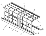
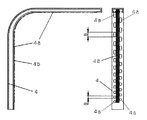
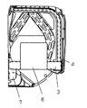
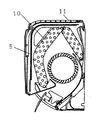
図1は本発明の実施の形態におけるフィルター装置の斜視図、図2は本発明の実施の形態におけるフィルター装置の吸入ノズルの外観図、図3は発明の実施の形態における室内機の正面図、図4、図5は本発明の実施の形態における空気調和機の断面図である。
【0013】
空気調和機本体11の内部には、熱交換器10とファン(図示せず)が配設されており、本体11の前面から上面に渡り形成される複数の吸込口(図示せず)からは、ファンの動作により空気が吸い込まれ、これらの空気中に漂う塵埃は、前記吸込口と熱交換器10との間に設けたフィルター装置1で取り除かれる。
【0014】
このフィルター装置1は、フィルター枠2と、エアフィルター5と、移動可能な吸入ノズル4を設け、この吸入ノズル4に吸い込みダクト3を設け、さらに前記吸い込みダクト3に連結する吸引排気装置6と排気ダクト7を具備した空気調和機において、前記吸入ノズル4に複数個の可変吸入口4aを千鳥に設け、さらに前記複数個の可変吸入口4aの長さ寸法Bは、上方向及び奥方向に行くにしたがって大きくなるように設定している。さらに前記吸入口4aに隣接するブラシ4bを設けたものである。
【0015】
このように構成されたフィルター装置1の動作について説明する。空気調和機本体11の運転停止後に、吸引排気装置6が運転開始し、吸い込みダクト3に設置された吸入ノズル4の吸入口4aから空気を吸い込み始める。そして、エアフィルター5の片側端に位置していた吸入ノズル4が、駆動モータ9に連結された駆動用ワイヤー8によって矢印A方向に移動し、吸入ノズル4のブラシ4bがエアフィルター5の表面についた埃を掻き出しながら、吸入ノズル4の複数個の可変吸入口4aから吸い取り、塵埃は吸い込みダクト3、吸引排気装置6を通り、排気ダクト7から室外へ吐き出される。
【0016】
ここで、吸入ノズル4がエアフィルター5の表面を全面清掃し、対向する片側端まで移動したときに駆動モータ9を逆回転させれば、吸入ノズル4は初期の位置に戻る方向に移動して、もう一度エアフィルター5の表面を清掃することが可能となる。
【0017】
そして、この実施例によれば、吸入ノズル4の手前から奥まで均一にムラなく吸塵することができる。
【0018】
【発明の効果】
上記から明らかなように、本発明は、フィルター装置にフィルター枠と、エアフィルターと、移動可能な吸入ノズルを設け、この吸入ノズルに吸い込みダクトを設け、さらに前記吸い込みダクトに連結する吸引排気装置と排気ダクトを具備した空気調和機において、前記吸入ノズルに複数個の可変吸入口を千鳥に設け、さらに前記吸入口に隣接するブラシを設けたものである。この構成によれば、ノズルの手前から奥まで均一にムラなく吸塵することができるという効果を奏する。
【図面の簡単な説明】
【図1】本発明の一実施例を示すフィルター装置の斜視図
【図2】本発明の一実施例を示すフィルター装置の吸入ノズルの断面外観図
【図3】本発明の一実施例を示す空気調和機の正面図
【図4】本発明の一実施例を示す図3のI−Iによる空気調和機の断面図
【図5】本発明の一実施例を示す図3のII−IIによる空気調和機の断面図
【図6】従来を示す空気調和機の断面図
【符号の説明】
1 フィルター装置
2 フィルター枠
3 吸い込みダクト
4 吸入ノズル
4a 可変吸入口
4b ブラシ
5 エアフィルター
6 吸引排気装置
7 排気ダクト
8 駆動用ワイヤー
9 駆動モータ
10 熱交換器
11 本体[0001]
TECHNICAL FIELD OF THE INVENTION
The present invention relates to a filter device of an air conditioner that automatically cleans a filter.
[0002]
[Prior art]
As shown in FIG. 6, the filter device of the conventional air conditioner is provided with an
[0003]
On the other hand, as an air conditioner in which an air filter can be easily cleaned, there is a type in which a rotating brush, a brush cover, and a filter brush including a pinion provided coaxially with the rotating brush are configured as an air filter cleaning unit. (For example, see Patent Document 1).
[0004]
Further, there is a collecting device, a cleaning device, a suction mechanism, a carrier beam connected to the suction mechanism, a hose connected to the carrier beam, a vacuum generator, and the like (for example, Patent Document 2).
[0005]
Further, a drive shaft and a driven shaft having a belt-shaped filter stretched thereon, a servomotor, a brush, a dust sensor and a fan disposed in an exhaust pipe, and arithmetic processing means for calculating a continuous use time of the filter. And control means (for example, see Patent Document 3).
[0006]
[Patent Document 1]
JP-A-11-226331 (page 2, FIG. 1 to FIG. 4)
[Patent Document 2]
JP-A-1-75020 (
[Patent Document 3]
JP-A-6-74521 (page 2, FIG. 1)
[0007]
[Problems to be solved by the invention]
However, the above-described conventional filter configuration requires periodic maintenance such as removing the air conditioner from the air conditioner in accordance with the frequency of use of the air conditioner, and washing the attached dust with water or a vacuum cleaner. In addition, when the periodic maintenance is not performed, dust accumulates on the air filter, and the ventilation resistance of the intake air increases, so that the performance of the air conditioner decreases and the power consumption increases.
[0008]
In addition, there are restrictions on the operation means, and the time and effort for dust treatment after dust collection are increased, so that the method is not reliable. In addition, there is a problem that the body size is enlarged.
[0009]
[Means for Solving the Problems]
In order to solve the above problems, a filter device of the present invention includes a filter frame, an air filter, a movable suction nozzle, a suction duct provided in the suction nozzle, and a suction / exhaust device connected to the suction duct. And an air conditioner provided with an exhaust duct, wherein a plurality of variable suction ports are provided in a staggered manner in the suction nozzle.
[0010]
According to the above configuration, it is possible to automatically clean the air filter, thereby maintaining the performance of the air conditioner and preventing an increase in power consumption. Further, dust can be uniformly absorbed from the front to the back of the nozzle without unevenness.
[0011]
BEST MODE FOR CARRYING OUT THE INVENTION
Hereinafter, embodiments of the present invention will be described with reference to the drawings.
[0012]
1 is a perspective view of a filter device according to an embodiment of the present invention, FIG. 2 is an external view of a suction nozzle of the filter device according to an embodiment of the present invention, FIG. 3 is a front view of an indoor unit according to the embodiment of the present invention, 4 and 5 are cross-sectional views of the air conditioner according to the embodiment of the present invention.
[0013]
Inside the air conditioner
[0014]
The
[0015]
The operation of the
[0016]
Here, if the
[0017]
According to this embodiment, dust can be uniformly and uniformly absorbed from the front to the back of the
[0018]
【The invention's effect】
As is apparent from the above, the present invention provides a filter frame, an air filter, and a movable suction nozzle in a filter device, a suction duct provided in the suction nozzle, and a suction and exhaust device connected to the suction duct. In an air conditioner provided with an exhaust duct, a plurality of variable suction ports are provided in a zigzag manner in the suction nozzle, and a brush adjacent to the suction port is provided. According to this configuration, there is an effect that dust can be uniformly and uniformly absorbed from the front to the back of the nozzle.
[Brief description of the drawings]
1 is a perspective view of a filter device showing one embodiment of the present invention; FIG. 2 is a cross-sectional external view of a suction nozzle of the filter device showing one embodiment of the present invention; FIG. 3 shows one embodiment of the present invention; FIG. 4 is a front view of the air conditioner. FIG. 4 is a cross-sectional view of the air conditioner taken along a line II in FIG. 3 illustrating an embodiment of the present invention. FIG. Sectional view of air conditioner [Figure 6] Sectional view of conventional air conditioner [Description of symbols]
DESCRIPTION OF
Claims (2)
Priority Applications (1)
| Application Number | Priority Date | Filing Date | Title |
|---|---|---|---|
| JP2003080292A JP4107119B2 (en) | 2003-03-24 | 2003-03-24 | Air conditioner filter device |
Applications Claiming Priority (1)
| Application Number | Priority Date | Filing Date | Title |
|---|---|---|---|
| JP2003080292A JP4107119B2 (en) | 2003-03-24 | 2003-03-24 | Air conditioner filter device |
Publications (2)
| Publication Number | Publication Date |
|---|---|
| JP2004286345A true JP2004286345A (en) | 2004-10-14 |
| JP4107119B2 JP4107119B2 (en) | 2008-06-25 |
Family
ID=33294194
Family Applications (1)
| Application Number | Title | Priority Date | Filing Date |
|---|---|---|---|
| JP2003080292A Expired - Fee Related JP4107119B2 (en) | 2003-03-24 | 2003-03-24 | Air conditioner filter device |
Country Status (1)
| Country | Link |
|---|---|
| JP (1) | JP4107119B2 (en) |
Cited By (19)
| Publication number | Priority date | Publication date | Assignee | Title |
|---|---|---|---|---|
| JP2006105590A (en) * | 2005-11-29 | 2006-04-20 | Matsushita Electric Ind Co Ltd | Filter device for air-conditioner |
| JP2006105591A (en) * | 2005-11-29 | 2006-04-20 | Matsushita Electric Ind Co Ltd | Filter device for air-conditioner |
| WO2006043534A1 (en) * | 2004-10-19 | 2006-04-27 | Matsushita Electric Industrial Co., Ltd. | Filter device for air conditioner |
| WO2006046409A1 (en) * | 2004-10-26 | 2006-05-04 | Matsushita Electric Industrial Co., Ltd. | Air conditioner having indoor unit with automatic cleaning function for air filter |
| WO2006049060A1 (en) * | 2004-11-05 | 2006-05-11 | Matsushita Electric Industrial Co., Ltd. | Air conditioner |
| WO2006049244A1 (en) * | 2004-11-08 | 2006-05-11 | Matsushita Electric Industrial Co., Ltd. | Air conditioner |
| WO2006049043A1 (en) * | 2004-11-05 | 2006-05-11 | Matsushita Electric Industrial Co., Ltd. | Air conditioner |
| WO2006051740A1 (en) * | 2004-11-10 | 2006-05-18 | Matsushita Electric Industrial Co., Ltd. | Air conditioner having indoor unit with automatic air filter cleaning function |
| WO2006051739A1 (en) * | 2004-11-09 | 2006-05-18 | Matsushita Electric Industrial Co., Ltd. | Air conditioner |
| JP2006214721A (en) * | 2004-10-27 | 2006-08-17 | Matsushita Electric Ind Co Ltd | Air conditioner |
| JP2006220412A (en) * | 2004-11-08 | 2006-08-24 | Matsushita Electric Ind Co Ltd | Air conditioner |
| JP2007237091A (en) * | 2006-03-09 | 2007-09-20 | Matsushita Electric Ind Co Ltd | Air cleaner |
| BE1019010A4 (en) * | 2010-05-18 | 2011-12-06 | Bvba Handelsmij Willy Deweerdt | DEVICE FOR REMOVING ICE CRYSTALS. |
| KR101327464B1 (en) | 2006-12-22 | 2013-11-08 | 엘지전자 주식회사 | Air conditioner |
| JP2015528560A (en) * | 2012-09-04 | 2015-09-28 | ボルボ コンストラクション イクイップメント アーベー | Cleaning system for cooling equipment for construction machinery |
| CN105057283A (en) * | 2015-08-14 | 2015-11-18 | 珠海格力电器股份有限公司 | Cleaning mechanism, cleaning device and air conditioner |
| EP2154442A4 (en) * | 2007-04-18 | 2016-05-25 | Haier Group Corp | Self-cleaning device of filtering net and air conditioner having it |
| TWI636823B (en) * | 2016-10-19 | 2018-10-01 | 夏普股份有限公司 | Air cleaner |
| CN108758948A (en) * | 2018-06-26 | 2018-11-06 | 安徽应力环保科技有限公司 | A kind of integrated-type fresh air conditioner all-in-one machine |
-
2003
- 2003-03-24 JP JP2003080292A patent/JP4107119B2/en not_active Expired - Fee Related
Cited By (28)
| Publication number | Priority date | Publication date | Assignee | Title |
|---|---|---|---|---|
| WO2006043534A1 (en) * | 2004-10-19 | 2006-04-27 | Matsushita Electric Industrial Co., Ltd. | Filter device for air conditioner |
| CN100427838C (en) * | 2004-10-19 | 2008-10-22 | 松下电器产业株式会社 | Filter apparatus for air conditioner |
| WO2006046409A1 (en) * | 2004-10-26 | 2006-05-04 | Matsushita Electric Industrial Co., Ltd. | Air conditioner having indoor unit with automatic cleaning function for air filter |
| JP2006214721A (en) * | 2004-10-27 | 2006-08-17 | Matsushita Electric Ind Co Ltd | Air conditioner |
| JP4843500B2 (en) * | 2004-11-05 | 2011-12-21 | パナソニック株式会社 | Air conditioner |
| WO2006049060A1 (en) * | 2004-11-05 | 2006-05-11 | Matsushita Electric Industrial Co., Ltd. | Air conditioner |
| WO2006049043A1 (en) * | 2004-11-05 | 2006-05-11 | Matsushita Electric Industrial Co., Ltd. | Air conditioner |
| JPWO2006049060A1 (en) * | 2004-11-05 | 2008-05-29 | 松下電器産業株式会社 | Air conditioner |
| JPWO2006049244A1 (en) * | 2004-11-08 | 2008-05-29 | 松下電器産業株式会社 | Air conditioner |
| WO2006049244A1 (en) * | 2004-11-08 | 2006-05-11 | Matsushita Electric Industrial Co., Ltd. | Air conditioner |
| JP2006220412A (en) * | 2004-11-08 | 2006-08-24 | Matsushita Electric Ind Co Ltd | Air conditioner |
| WO2006051739A1 (en) * | 2004-11-09 | 2006-05-18 | Matsushita Electric Industrial Co., Ltd. | Air conditioner |
| WO2006051740A1 (en) * | 2004-11-10 | 2006-05-18 | Matsushita Electric Industrial Co., Ltd. | Air conditioner having indoor unit with automatic air filter cleaning function |
| JPWO2006051740A1 (en) * | 2004-11-10 | 2008-05-29 | 松下電器産業株式会社 | Air conditioner with indoor unit with automatic air filter cleaning function |
| JP4932491B2 (en) * | 2004-11-10 | 2012-05-16 | パナソニック株式会社 | Air conditioner with indoor unit with automatic air filter cleaning function |
| JP2006105590A (en) * | 2005-11-29 | 2006-04-20 | Matsushita Electric Ind Co Ltd | Filter device for air-conditioner |
| JP2006105591A (en) * | 2005-11-29 | 2006-04-20 | Matsushita Electric Ind Co Ltd | Filter device for air-conditioner |
| JP2007237091A (en) * | 2006-03-09 | 2007-09-20 | Matsushita Electric Ind Co Ltd | Air cleaner |
| KR101327464B1 (en) | 2006-12-22 | 2013-11-08 | 엘지전자 주식회사 | Air conditioner |
| EP2154442A4 (en) * | 2007-04-18 | 2016-05-25 | Haier Group Corp | Self-cleaning device of filtering net and air conditioner having it |
| BE1019010A4 (en) * | 2010-05-18 | 2011-12-06 | Bvba Handelsmij Willy Deweerdt | DEVICE FOR REMOVING ICE CRYSTALS. |
| JP2015528560A (en) * | 2012-09-04 | 2015-09-28 | ボルボ コンストラクション イクイップメント アーベー | Cleaning system for cooling equipment for construction machinery |
| CN105057283A (en) * | 2015-08-14 | 2015-11-18 | 珠海格力电器股份有限公司 | Cleaning mechanism, cleaning device and air conditioner |
| WO2017028710A1 (en) * | 2015-08-14 | 2017-02-23 | 珠海格力电器股份有限公司 | Cleaning mechanism, cleaning device and air conditioner |
| US10814359B2 (en) | 2015-08-14 | 2020-10-27 | Gree Electric Appliances, Inc. Of Zhuhai | Cleaning mechanism, cleaning device and air conditioner |
| TWI636823B (en) * | 2016-10-19 | 2018-10-01 | 夏普股份有限公司 | Air cleaner |
| CN108758948A (en) * | 2018-06-26 | 2018-11-06 | 安徽应力环保科技有限公司 | A kind of integrated-type fresh air conditioner all-in-one machine |
| CN108758948B (en) * | 2018-06-26 | 2023-05-09 | 安徽应力环保科技有限公司 | Integrated fresh air conditioner all-in-one machine |
Also Published As
| Publication number | Publication date |
|---|---|
| JP4107119B2 (en) | 2008-06-25 |
Similar Documents
| Publication | Publication Date | Title |
|---|---|---|
| JP2004286345A (en) | Filter device of air conditioner | |
| JP2004283703A (en) | Filter system for air conditioner | |
| JP2006071121A (en) | Air-conditioner | |
| JP4350705B2 (en) | Air conditioner with indoor unit with automatic air filter cleaning function | |
| WO2006043430A1 (en) | Air conditioner | |
| KR20080007858A (en) | Air conditioner | |
| WO2004079271A1 (en) | Air conditioner having indoor unit with automatic air filter celaning function | |
| JP2004283704A (en) | Filter system for air conditioner | |
| JP2004156794A (en) | Air conditioner | |
| JPWO2004079270A1 (en) | Air conditioner with indoor unit with automatic air filter cleaning function | |
| JP2006183996A (en) | Air conditioner | |
| JP4360105B2 (en) | Air conditioner | |
| JP2006102747A (en) | Air conditioner | |
| JP2008111580A (en) | Filter cleaning device and air conditioner | |
| JP3992722B2 (en) | Air conditioner | |
| JP4860131B2 (en) | Method for controlling dust suction device of air conditioner | |
| JP4134768B2 (en) | Air conditioner | |
| WO2004083735A1 (en) | Air conditioner having indoor unit with automatic air filter-cleaning function | |
| JP2007127289A (en) | Air conditioner | |
| JP2015140996A (en) | air conditioner | |
| JP5092409B2 (en) | Air conditioner | |
| JP2010127515A (en) | Filter cleaning device and air conditioning device | |
| JP2008032249A (en) | Cleaning device for filter | |
| JP2004286344A (en) | Air conditioner | |
| CN108644957A (en) | New airing radiator |
Legal Events
| Date | Code | Title | Description |
|---|---|---|---|
| A621 | Written request for application examination |
Free format text: JAPANESE INTERMEDIATE CODE: A621 Effective date: 20050713 |
|
| RD01 | Notification of change of attorney |
Free format text: JAPANESE INTERMEDIATE CODE: A7421 Effective date: 20050816 |
|
| A977 | Report on retrieval |
Free format text: JAPANESE INTERMEDIATE CODE: A971007 Effective date: 20070516 |
|
| A131 | Notification of reasons for refusal |
Free format text: JAPANESE INTERMEDIATE CODE: A131 Effective date: 20070612 |
|
| A521 | Request for written amendment filed |
Free format text: JAPANESE INTERMEDIATE CODE: A523 Effective date: 20070718 |
|
| A02 | Decision of refusal |
Free format text: JAPANESE INTERMEDIATE CODE: A02 Effective date: 20071023 |
|
| A521 | Request for written amendment filed |
Free format text: JAPANESE INTERMEDIATE CODE: A523 Effective date: 20071128 |
|
| A911 | Transfer to examiner for re-examination before appeal (zenchi) |
Free format text: JAPANESE INTERMEDIATE CODE: A911 Effective date: 20071228 |
|
| TRDD | Decision of grant or rejection written | ||
| A01 | Written decision to grant a patent or to grant a registration (utility model) |
Free format text: JAPANESE INTERMEDIATE CODE: A01 Effective date: 20080311 |
|
| A61 | First payment of annual fees (during grant procedure) |
Free format text: JAPANESE INTERMEDIATE CODE: A61 Effective date: 20080324 |
|
| FPAY | Renewal fee payment (event date is renewal date of database) |
Free format text: PAYMENT UNTIL: 20110411 Year of fee payment: 3 |
|
| FPAY | Renewal fee payment (event date is renewal date of database) |
Free format text: PAYMENT UNTIL: 20110411 Year of fee payment: 3 |
|
| LAPS | Cancellation because of no payment of annual fees |