JP2008106922A - Shaft locking structure of constant velocity universal joint - Google Patents
Shaft locking structure of constant velocity universal joint Download PDFInfo
- Publication number
- JP2008106922A JP2008106922A JP2006292964A JP2006292964A JP2008106922A JP 2008106922 A JP2008106922 A JP 2008106922A JP 2006292964 A JP2006292964 A JP 2006292964A JP 2006292964 A JP2006292964 A JP 2006292964A JP 2008106922 A JP2008106922 A JP 2008106922A
- Authority
- JP
- Japan
- Prior art keywords
- shaft
- constant velocity
- universal joint
- inner ring
- fitting recess
- Prior art date
- Legal status (The legal status is an assumption and is not a legal conclusion. Google has not performed a legal analysis and makes no representation as to the accuracy of the status listed.)
- Withdrawn
Links
- 238000003780 insertion Methods 0.000 claims abstract description 41
- 230000037431 insertion Effects 0.000 claims abstract description 41
- 230000002708 enhancing effect Effects 0.000 abstract 1
- 230000002093 peripheral effect Effects 0.000 description 8
- 238000000034 method Methods 0.000 description 3
- 230000004323 axial length Effects 0.000 description 1
- 230000005540 biological transmission Effects 0.000 description 1
- 230000008878 coupling Effects 0.000 description 1
- 238000010168 coupling process Methods 0.000 description 1
- 238000005859 coupling reaction Methods 0.000 description 1
- 230000000694 effects Effects 0.000 description 1
- 238000012986 modification Methods 0.000 description 1
- 230000004048 modification Effects 0.000 description 1
- 230000002265 prevention Effects 0.000 description 1
Images


Landscapes
- Snaps, Bayonet Connections, Set Pins, And Snap Rings (AREA)
Abstract
Description
本発明は、自動車や各種産業機器に使用される等速自在継手におけるシャフト抜け止め構造に関するものである。 The present invention relates to a shaft retaining structure in a constant velocity universal joint used in automobiles and various industrial equipment.
自動車や各種産業機械における動力の伝達に用いられる等速自在継手は、一般に、図5に示すように、内球面にトラック溝1が形成された外側継手部材としての外輪2と、外球面にトラック溝3が形成された内側継手部材としての内輪4と、前記外輪2のトラック溝1と内輪4のトラック溝3との間に介在してトルクを伝達する複数のボール5と、前記外輪2と内輪4との間に介在してボール5を保持するケージ6とを備える。
As shown in FIG. 5, a constant velocity universal joint used for power transmission in automobiles and various industrial machines is generally provided with an
シャフト7が内輪4の挿入孔4aに挿入されて、この内輪4とスプライン結合される。そのため、シャフト7は抜け止め構造によって軸方向の抜けが防止される。
The
従来のシャフトの抜け止め構造は、シャフト7に周方向溝(環状溝)10を設け、この周方向溝10に、一部に切欠部を有する止め輪11(以下C型クリップと呼ぶ)を嵌入させたものが一般的である(特許文献1及び特許文献2)。
In a conventional shaft retaining structure, a circumferential groove (annular groove) 10 is provided in the
特許文献1に記載の抜け止め構造は、この図5に示すように、シャフト7の端部のスプライン12に前記周方向溝(クリップ溝)10を設け、この周方向溝10にC型クリップ11を嵌合させる。シャフト7が挿入される内輪5には、その内周面に反挿入側の端部に、クリップ溝10に対向する周方向溝13が設けられる。C型クリップ11をやや縮径状態にしてクリップ溝10に嵌合し、この状態でシャフト7を内輪4の挿入孔4aに挿入する。C型クリップ11の外周側が内輪5の周方向溝13に出会うことにより、C型クリップ11が拡径してその外周側が内輪4の周方向溝13に嵌合される。
As shown in FIG. 5, the retaining structure described in Patent Document 1 is provided with the circumferential groove (clip groove) 10 in the
また、特許文献2に記載の抜け止め構造は、内輪入り口側(シャフト挿入側)にクリップ溝を形成したものである。すなわち、図7に示すように、シャフト7に断面三角形状の凸部15を設けるとともに、内輪入り口側(シャフト挿入側)にクリップ溝16を形成し、シャフト7を挿入した状態で、このクリップ溝16にクリップ11が嵌合するようにしている。
C型クリップ11は、その外径を自由状態においてシャフト外径よりも大きくすると共に、C型クリップ11の内径をシャフト7の周方向溝10の底面径よりも大きくしている。そして、シャフト7を内輪4に組み付ける際には、前述のようにC型クリップ11を内輪4の挿入孔4aに挿入可能なように縮径させると共に、C型クリップ11の軸心をシャフト軸心に合わせる調芯を行なう必要があった。そこで、前記特許文献1に記載のものでは、図6に示すように、この調芯のためにシャフト7の周方向溝に弾性部材14を嵌合させていた。
The C-
このため、特許文献1のような従来のシャフト抜け構造では、C型クリップ11及び調芯のための弾性部材14を必要として、部品点数が多く、コスト高となっていた。しかも、スプライン12に周方向溝を設けているので、スプライン結合を安定させるため、スプライン全体の軸方向長さを大きくする必要があった。さらに、シャフト7を内輪4の挿入孔4aに挿入する際には、C型クリップ11を内輪4の挿入孔4aに挿入可能なように縮径させるので、シャフト7を内輪に組み付けた後に、C型クリップ11が確実に拡径しているか否かの確認作業が不可能であった。
For this reason, in the conventional shaft removal structure like patent document 1, the C-shaped
また、特許文献2に記載のシャフト抜け構造では、シャフト7の断面三角形状の凸部15の一方の(外側の)傾斜面15aと、これに対面(対向)するクリップ溝16の一方の傾斜壁16aとの間にクリップ11を介在させ、シャフト7の抜けを防止している。
Moreover, in the shaft omission structure described in
このため、凸部15の傾斜面15aの傾斜角度α、クリップ溝16の傾斜壁16aの傾斜角度β、凸部15の高さ、及びクリップ溝16の深さを精度よく設定しなければ、シャフト7を挿入させにくく、かつシャフト7の抜けを防止できないおそれがある。
Therefore, if the inclination angle α of the
本発明は、上記課題に鑑みて、部品点数を減少させて、シャフトの内輪への組み付け作業の簡略化を図ることができ、しかもシャフト抜け防止の信頼性の向上を図ることが可能な等速自在継手のシャフト抜け止め構造を提供する。 In view of the above problems, the present invention can reduce the number of parts, simplify the assembly work of the shaft to the inner ring, and can improve the reliability of preventing the shaft from coming off. Provided is a universal joint shaft retaining structure.
本発明の等速自在継手のシャフト抜け止め構造は、等速自在継手の内側継手部材の挿入孔に挿入されて、この内側継手部材とスプライン結合されたシャフトの抜け止め構造において、内側継手部材の挿入孔の反シャフト挿入側に嵌合凹所を設けるとともに、シャフト挿入端部に、内側継手部材の挿入孔への挿入にて塑性変形して前記嵌合凹所に嵌合する突起部を設けたものである。 The shaft retaining structure of the constant velocity universal joint according to the present invention is inserted into the insertion hole of the inner joint member of the constant velocity universal joint, and in the shaft retaining structure splined with the inner joint member, A fitting recess is provided on the side opposite to the shaft insertion side of the insertion hole, and a protrusion that is plastically deformed by insertion into the insertion hole of the inner joint member and fitted in the fitting recess is provided at the shaft insertion end. It is a thing.
本発明の等速自在継手のシャフト抜け止め構造によれば、シャフトを内側継手部材の挿入孔に挿入すれば、シャフト挿入端部に設けられた突起部が塑性変形して内側継手部材の嵌合凹所に嵌合する。これによって、シャフトの内側継手部材の挿入孔からの抜けを防止できる。 According to the shaft retaining structure of the constant velocity universal joint of the present invention, when the shaft is inserted into the insertion hole of the inner joint member, the protrusion provided at the shaft insertion end is plastically deformed to fit the inner joint member. Mates into the recess. Thereby, it is possible to prevent the inner joint member of the shaft from coming off from the insertion hole.
また、前記嵌合凹所は周方向に沿って形成される周方向溝であるとともに、突起部が周方向に沿って形成される周方向凸部であっても、突起部が周方向に沿って所定ピッチで配設される小突起であってもよい。前記突起部は、シャフト挿入時にシャフト端面を受ける治具にガイドされて塑性変形することになる。 Further, the fitting recess is a circumferential groove formed along the circumferential direction, and the protruding portion extends along the circumferential direction even if the protruding portion is a circumferential convex portion formed along the circumferential direction. Small protrusions arranged at a predetermined pitch may be used. The protrusion is plastically deformed by being guided by a jig that receives the shaft end surface when the shaft is inserted.
本発明は、シャフト挿入端部に設けられた突起部が塑性変形して内側継手部材の嵌合凹所に嵌合することによって、シャフトの抜けを防止できる。このため、従来必要としていたサークリップ溝加工が不要となって、生産性の向上を図るとともに、サークリップ(止め輪)を必要とせず、部品点数の減少を図ってコストの低減を達成できる。しかも、確実にシャフトの抜けを防止できる。 According to the present invention, the protrusion provided at the shaft insertion end is plastically deformed and fitted into the fitting recess of the inner joint member, thereby preventing the shaft from coming off. For this reason, the circlip groove processing, which has been conventionally required, is not required, so that productivity can be improved, a circlip (retaining ring) is not required, and the number of parts can be reduced to achieve cost reduction. Moreover, the shaft can be reliably prevented from coming off.
前記嵌合凹所は周方向に沿って形成される周方向溝であるとともに、突起部が周方向に沿って形成される周方向凸部であれば、周方向にわたって嵌合凹所に突起部が嵌合しており、シャフト抜け防止の信頼性の向上を図ることができる。また、突起部が周方向に沿って所定ピッチで配設される小突起であれば、塑性変形時に作用させる力(圧入力)を小さくでき、塑性変形作業の容易化を図ることができる。 The fitting recess is a circumferential groove formed along the circumferential direction, and if the protruding portion is a circumferential convex portion formed along the circumferential direction, the protruding portion projects into the fitting recess over the circumferential direction. Can be improved, and the reliability of preventing the shaft from coming off can be improved. Further, if the protrusions are small protrusions arranged at a predetermined pitch along the circumferential direction, the force (pressure input) applied during plastic deformation can be reduced, and plastic deformation work can be facilitated.
突起部は、シャフト挿入時にシャフト端面を受ける治具にガイドされて塑性変形するようにすれば、組立性の向上を図ることができるとともに、塑性変形させた突起部を嵌合凹所に確実に嵌合させることができ、抜け防止の信頼性に優れた高品質のシャフト抜け止め構造となる。 If the protrusion is guided and plastically deformed by a jig that receives the shaft end surface when the shaft is inserted, the assemblability can be improved and the plastically deformed protrusion can be securely inserted into the fitting recess. A high-quality shaft retaining structure that can be fitted and has excellent reliability in preventing slipping is obtained.
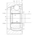
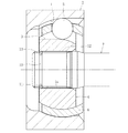
以下本発明の実施の形態を図1〜図4に基づいて説明する。図1に本発明に係るシャフト抜け止め構造を用いた等速自在継手を示す。この等速自在継手は、内周面に複数のトラック溝21を形成した外側継手部材としての外輪22と、外周面に複数のトラック溝23を形成した内側継手部材としての内輪24と、外輪22のトラック溝21と内輪24のトラック溝23とで協働して形成されるボールトラックに配される複数のボール25と、ボール25を収容するためのポケット26aを有する保持器(ケージ)26等から構成される。
Hereinafter, embodiments of the present invention will be described with reference to FIGS. FIG. 1 shows a constant velocity universal joint using a shaft retaining structure according to the present invention. This constant velocity universal joint includes an
また、内輪24の軸心孔(挿入孔)24aにシャフト27が嵌合される。この場合、シャフト27の先端側外周には、スプライン28が形成され、内輪24の挿入孔24aの内周面には、スプライン29が形成されている。シャフト27のスプライン28と内輪24のスプライン29とを嵌合させることにより、内輪24とシャフト27とがトルク伝達可能に結合する。
Further, the
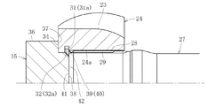
内輪24の反挿入側(シャフト27が内輪24に挿入される入り口30側と反対側の開口部側)の内周面(内径面)に周方向溝31aからなる嵌合凹所31が形成され、シャフト挿入端部(内輪24に挿入する側の端部)に嵌合凹所31に嵌合される周方向凸部からなる突起部32が設けられ、これらでもって本発明に係るシャフト抜け止め構造を構成することになる。なお、嵌合凹所31は、この実施形態では、その断面形状が矩形状とされている。
A
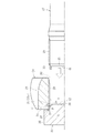
この突起部32は、嵌合凹所31に嵌合される前は、図2に示すように、短円筒形状体33であって、シャフト27の内輪24の挿入孔24aに挿入(圧入)することによって、塑性変形して、嵌合凹所31に嵌合する。なお、シャフト27の端縁部(内輪24に挿入する側の端縁部)にテーパ部45が設けられ、このテーパ部45の先細端縁部から前記短円筒形状体33が突出される。
The
内輪24にシャフト7を挿入する場合、図2に示す治具35を使用する。治具35は円盤体からなる大径本体部36と、この大径本体部36の内輪側の端面37から突設される小径突出部38とからなり、小径突出部38の外周側に面取り部39が形成されている。
When the
この治具35にて内輪24を受けることができ、この状態では、小径突出部38が内輪24の反シャフト挿入側開口部に嵌合する。小径突出部38の外径寸法Aと内輪24の反シャフト挿入側開口部の内径寸法Bとを同一とするとともに、大径本体部36の端面37から面取り部39までの寸法Cと、内輪24の反シャフト挿入側端面34から嵌合凹所31までの寸法Dとを同一に設定する。
The
これによって、内輪24の反シャフト挿入側端面34と、治具35に端面37とが当接するとともに、内輪24の嵌合凹所31より挿入側端面34までの範囲の内周面が治具35の小径突出部38の外周面に当接する。そして、嵌合凹所31の反シャフト挿入側端と、小径突出部38の面取り部39の本体部側端とが一致して、テーパ部39が塑性変形する際のガイド面40となる。
As a result, the
次にこの治具35を使用したシャフト27の内輪24への挿入方法を説明する。まず、図2に示すように、この治具35にて内輪24を受けた状態とする。すなわち、嵌合凹所31の反シャフト挿入側端と、小径突出部38の面取り部39の本体部側端とが一致している状態とする。
Next, a method for inserting the
そして、この状態で、内輪24に対してシャフト27を図2の矢印方向に沿って内輪24の挿入孔24aに挿入(圧入)して行く。この際、短円筒形状体33の先端縁が小径突出部38の面取り部39であるガイド面40に当接する。この当接した状態からさらにシャフト27を図2の矢印方向に圧入して行けば、短円筒形状体33の先端縁が、反シャフト挿入側に向かって拡径しているガイド面40に沿って拡径しつつ嵌合凹所31に嵌入されるように塑性変形する。
In this state, the
図3に示すように、シャフト27の端面41が治具35の小径突出部38の端面42に当接するまで、シャフト27を圧入することによって、塑性変形した短円筒形状体33が嵌合凹所31に嵌合した状態となって、周方向凸部32aからなる突起部32が形成される。このように、嵌合凹所31に突起部32を嵌合した状態となれば、シャフト27の抜けが防止される。
As shown in FIG. 3, the
本発明では、シャフト挿入端部に設けられた突起部32が塑性変形して内側継手部材の嵌合凹所31に嵌合することによって、シャフト27の抜けを防止できる。このため、従来必要としていたサークリップ溝加工が不要となって、生産性の向上を図るとともに、サークリップ(止め輪)を必要とせず、部品点数の減少を図ってコストの低減を達成できる。しかも、確実にシャフト27の抜けを防止できる。
In the present invention, the
前記嵌合凹所31は周方向に沿って形成される周方向溝31aであるとともに、突起部が周方向に沿って形成される周方向凸部32aであれば、周方向にわたって嵌合凹所31に突起部32が嵌合しており、シャフト抜け防止の信頼性の向上を図ることができる。
The
突起部32は、シャフト挿入時にシャフト端面41を受ける治具35にガイドされて塑性変形するようにすれば、組立性の向上を図ることができるとともに、塑性変形させた突起部32を嵌合凹所31に確実に嵌合させることができ、抜け防止の信頼性に優れた高品質のシャフト抜け止め構造となる。
If the
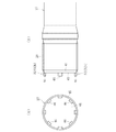
次に、図4は他の実施形態を示し、この場合、突起部32が周方向に沿って所定ピッチで配設される小突起32bである。この場合、小突起32bは周方向に沿って45度ピッチで8個設けられている。なお、塑性変形する前の小突起32bは扁平矩形体46である。
Next, FIG. 4 shows another embodiment. In this case, the
この場合であっても、内輪24に対してシャフト27を内輪24の挿入孔24aに挿入(圧入)して行くことによって、各扁平矩形体46の先端縁が小径突出部38の面取り部39であるガイド面40に当接する。この当接した状態からさらにシャフト27を圧入して行けば、各扁平矩形体46の先端縁が、反シャフト挿入側に向かって拡径しているガイド面40に沿って拡がりつつ嵌合凹所31に嵌入されるように塑性変形して、小突起32bからなる突出部32が形成される。
Even in this case, by inserting (press-fitting) the
このため、図4に示すような突起部32が図4に示すような小突起32bであっても、前記図2等に示すものと同様の作用効果を奏する。特に、突起部32が周方向に沿って所定ピッチで配設される小突起32bであれば、塑性変形時に作用させる力(圧入力)を小さくでき、塑性変形作業の容易化を図ることができる。
For this reason, even if the
以上、本発明の実施形態につき説明したが、本発明は前記実施形態に限定されることなく種々の変形が可能であって、例えば、複数個の小突起32bを設ける場合、シャフト27を内輪24に圧入した際に、塑性変形して嵌合凹所31に嵌合して、抜け止め機能を発揮できる範囲でその数、大きさ、配設ピッチ等を任意に変更できる。また、小突起32bを用いる場合、嵌合凹所31が周方向溝でなくて、各小突起32bに対応する位置に設けられる小凹所であってもよい。
The embodiment of the present invention has been described above. However, the present invention is not limited to the above-described embodiment, and various modifications are possible. For example, when a plurality of
また、突出部32としては、塑性変形させる必要があるので、硬化処理(熱処理)を施さないようにするのが好ましい。等速自在継手として、前記実施形態では、アンダーカットフリー型を例示しているが、他の固定式のツェッパー型等速自在継手であっても、さらには、トリポード型、クロスグルーブ型等の摺動式等速自在継手であってもよい。
Moreover, since it is necessary to carry out plastic deformation as the
24a 挿入孔
27 シャフト
31 嵌合凹所
32 突起部
35 治具
36 大径本体部
41 端面
46 小突起
Claims (4)
内側継手部材の挿入孔の反シャフト挿入側に嵌合凹所を設けるとともに、シャフト挿入端部に、内側継手部材の挿入孔への挿入にて塑性変形して前記嵌合凹所に嵌合する突起部を設けたことを特徴とする等速自在継手のシャフト抜け止め構造。 In the shaft retaining structure inserted into the insertion hole of the inner joint member of the constant velocity universal joint and splined with the inner joint member,
A fitting recess is provided on the side opposite to the shaft insertion side of the insertion hole of the inner joint member, and the shaft insertion end is plastically deformed by insertion into the insertion hole of the inner joint member and is fitted into the fitting recess. A structure for preventing the shaft of a constant velocity universal joint from being provided with a protrusion.
Priority Applications (1)
| Application Number | Priority Date | Filing Date | Title |
|---|---|---|---|
| JP2006292964A JP2008106922A (en) | 2006-10-27 | 2006-10-27 | Shaft locking structure of constant velocity universal joint |
Applications Claiming Priority (1)
| Application Number | Priority Date | Filing Date | Title |
|---|---|---|---|
| JP2006292964A JP2008106922A (en) | 2006-10-27 | 2006-10-27 | Shaft locking structure of constant velocity universal joint |
Publications (1)
| Publication Number | Publication Date |
|---|---|
| JP2008106922A true JP2008106922A (en) | 2008-05-08 |
Family
ID=39440426
Family Applications (1)
| Application Number | Title | Priority Date | Filing Date |
|---|---|---|---|
| JP2006292964A Withdrawn JP2008106922A (en) | 2006-10-27 | 2006-10-27 | Shaft locking structure of constant velocity universal joint |
Country Status (1)
| Country | Link |
|---|---|
| JP (1) | JP2008106922A (en) |
-
2006
- 2006-10-27 JP JP2006292964A patent/JP2008106922A/en not_active Withdrawn
Similar Documents
| Publication | Publication Date | Title |
|---|---|---|
| EP2806180B1 (en) | Constant velocity joint | |
| US5643092A (en) | Assembly for axially fixing a splined hub on a splined shaft | |
| JP5202887B2 (en) | Steering joint | |
| JP2018009583A (en) | Power transmission shaft | |
| JP2000074084A (en) | Falling stop device and constant velocity joint | |
| JP2009074594A (en) | Sliding type constant velocity universal joint | |
| JP2009174661A (en) | Constant velocity universal joint | |
| JP2007092932A (en) | Shaft coming-off prevention structure of constant velocity universal joint | |
| JP2008298267A (en) | Shaft clamp of joint for steering | |
| JP2007024088A (en) | Shaft fitting structure for constant velocity universal joint | |
| JP6486694B2 (en) | Constant velocity universal joint | |
| JP2008115997A (en) | Snap ring | |
| JP2006266460A (en) | Structure for preventing constant velocity joint shaft from coming off | |
| JP2008232300A (en) | Shaft coming-off prevention structure of constant velocity universal joint, constant velocity universal joint, and its manufacturing method | |
| JP2010025316A (en) | Inner joint member of constant velocity universal joint, method for assembling constant velocity universal joint, drive shaft assembly, and propeller shaft assembly | |
| JP2009127637A (en) | Constant velocity universal joint | |
| JP2008038959A (en) | Shaft coming-off preventive structure | |
| JP2009047224A (en) | Fall-out preventive structure, and constant velocity universal joint | |
| JP2010106942A (en) | Double offset type constant velocity universal joint | |
| JP2008089148A (en) | Constant velocity universal joint assembling method | |
| JP2010019346A (en) | Inner side joint member for constant velocity universal joint, assembly method for constant velocity universal joint, drive shaft assembly, and propeller shaft assembly | |
| JP2007263161A (en) | Shaft fitting structure | |
| JP2008089150A (en) | Shaft locking structure | |
| JP2007303531A (en) | Shaft fitting structure of constant velocity joint | |
| JP2010127338A (en) | Constant velocity universal joint and drive shaft assembly |
Legal Events
| Date | Code | Title | Description |
|---|---|---|---|
| A300 | Withdrawal of application because of no request for examination |
Free format text: JAPANESE INTERMEDIATE CODE: A300 Effective date: 20100105 |