JP2008051805A - Feed-water controller, nuclear power plant, and method for controlling feed-water - Google Patents

Feed-water controller, nuclear power plant, and method for controlling feed-water Download PDF

Info

Publication number
JP2008051805A
JP2008051805A JP2007183096A JP2007183096A JP2008051805A JP 2008051805 A JP2008051805 A JP 2008051805A JP 2007183096 A JP2007183096 A JP 2007183096A JP 2007183096 A JP2007183096 A JP 2007183096A JP 2008051805 A JP2008051805 A JP 2008051805A
Authority
JP
Japan
Prior art keywords
water
water supply
feed
flow rate
pumps
Prior art date
Legal status (The legal status is an assumption and is not a legal conclusion. Google has not performed a legal analysis and makes no representation as to the accuracy of the status listed.)
Granted
Application number
JP2007183096A
Other languages
Japanese (ja)
Other versions
JP4709809B2 (en
Inventor
Masaya Tominaga
真哉 富永
Current Assignee (The listed assignees may be inaccurate. Google has not performed a legal analysis and makes no representation or warranty as to the accuracy of the list.)
Toshiba Corp
Original Assignee
Toshiba Corp
Priority date (The priority date is an assumption and is not a legal conclusion. Google has not performed a legal analysis and makes no representation as to the accuracy of the date listed.)
Filing date
Publication date
Application filed by Toshiba Corp filed Critical Toshiba Corp
Priority to JP2007183096A priority Critical patent/JP4709809B2/en
Publication of JP2008051805A publication Critical patent/JP2008051805A/en
Application granted granted Critical
Publication of JP4709809B2 publication Critical patent/JP4709809B2/en
Expired - Fee Related legal-status Critical Current
Anticipated expiration legal-status Critical

Links

Images

Classifications

    • YGENERAL TAGGING OF NEW TECHNOLOGICAL DEVELOPMENTS; GENERAL TAGGING OF CROSS-SECTIONAL TECHNOLOGIES SPANNING OVER SEVERAL SECTIONS OF THE IPC; TECHNICAL SUBJECTS COVERED BY FORMER USPC CROSS-REFERENCE ART COLLECTIONS [XRACs] AND DIGESTS
    • Y02TECHNOLOGIES OR APPLICATIONS FOR MITIGATION OR ADAPTATION AGAINST CLIMATE CHANGE
    • Y02EREDUCTION OF GREENHOUSE GAS [GHG] EMISSIONS, RELATED TO ENERGY GENERATION, TRANSMISSION OR DISTRIBUTION
    • Y02E30/00Energy generation of nuclear origin

Landscapes

  • Control Of Positive-Displacement Pumps (AREA)
  • Monitoring And Testing Of Nuclear Reactors (AREA)

Abstract

<P>PROBLEM TO BE SOLVED: To reduce the possibility of scram of a nuclear reactor when one of feed-water pumps trips. <P>SOLUTION: The feed-water controller 7 of a nuclear power plant having three or more feed-water pumps 4a, 4b and 4c supplying water to the reactor vessel 1, electric motors 5a, 5b and 5c driving the feed-water pumps 4a, 4b and 4c and electric power converters 6a, 6b and 6c connected to the electric motors 5a, 5b and 5c is equipped with a water level controller, a flow rate controller, and a trip compensation means. The water level controller calculates a feed-water flow rate to the reactor vessel 1 based on the detected amount indicating the state of the nuclear power plant and a preset value of the water level of the reactor vessel 1, and outputs it as a feed-water flow rate command signal. The flow rate controller generates a rotation speed command signal for the electric motors based on the flow rate command signal. If one of the feed-water pumps 4a, 4b and 4c trips, the trip compensation means increases the rotation speed of the electric motors for driving the feed-water pumps that do not trip. <P>COPYRIGHT: (C)2008,JPO&INPIT

Description

本発明は、給水制御装置およびこれを用いる原子力発電プラント、ならびに、給水制御方法に関する。   The present invention relates to a water supply control device, a nuclear power plant using the same, and a water supply control method.

原子炉への給水流量の制御方法として、タービン駆動原子炉給水ポンプの回転数制御と電動機駆動原子炉給水ポンプの給水調節弁制御が知られている。   As control methods of the feed water flow rate to the nuclear reactor, there are known rotation speed control of a turbine driven nuclear reactor water pump and feed water control valve control of an electric motor driven nuclear reactor water pump.

それに対して、電力変換器を用いた回転数可変の電動機で給水ポンプを駆動する給水装置が検討されている(たとえば特許文献1参照)。この給水装置では、電動機駆動原子炉給水ポンプのうち1台が何らかの原因により給水できない状態(トリップ)となった場合には、予備の電動機駆動原子炉給水ポンプがインタロックにより急速に立ち上がりバックアップ起動するようになっている。
特公昭61−59479号公報
On the other hand, the water supply apparatus which drives a water supply pump with the electric motor of the rotation speed variable using a power converter is examined (for example, refer patent document 1). In this water supply device, when one of the motor-driven nuclear reactor water pumps cannot supply water due to any cause (trip), the backup electric motor-driven nuclear reactor water pump quickly rises due to the interlock and starts backup. It is like that.
Japanese Patent Publication No. 61-59479

電動機を急速に立ち上げる時には、通常の運転時と比較して大きな電流を必要とする。これに対し、電力変換器に流せる電流には制限があり、電動機には制限範囲内での電流しか供給することができない。そのため、電動機が起動を完了するのに時間を要する。一方、電動機を急速に立ち上げるために必要な電流を流せるような電力供給装置を設置する場合には、通常運転に必要な容量以上の電力供給装置を設置せざるを得ないため、経済的ではない。   When the motor is started up rapidly, a large current is required as compared with normal operation. On the other hand, there is a limit to the current that can be passed through the power converter, and the motor can only supply a current within the limit range. Therefore, it takes time for the electric motor to complete startup. On the other hand, when installing a power supply device that can supply the current necessary to start up the motor rapidly, it is unavoidable to install a power supply device that exceeds the capacity required for normal operation. Absent.

このため、大容量の電力供給装置を設置しない場合には、バックアップ起動の信号が入っても、予備の給水ポンプおよび駆動する電動機は停止状態から最低回転数に到達するまでに約10秒を要し、また定格回転数に達するまでには約15秒程度を必要とするのが通例である。   For this reason, if a large-capacity power supply device is not installed, even if a backup activation signal is input, it takes about 10 seconds for the auxiliary water supply pump and the driving motor to reach the minimum number of rotations from the stopped state. In addition, it usually takes about 15 seconds to reach the rated rotational speed.

また、給水ポンプ1台のトリップにより給水流量は急激に減少する。一方、バックアップ起動した予備の給水ポンプの始動特性は遅く定格流量に達するまでには長い時間を要するため、予備の給水ポンプを設置し、起動しているにもかかわらず、原子炉水位も低下し続けて、原子炉がスクラムするおそれがある。   In addition, the water supply flow rate rapidly decreases due to a trip of one water supply pump. On the other hand, since the start-up characteristics of the backup water pump that started up as a backup are slow and it takes a long time to reach the rated flow rate, the reactor water level also drops even though the backup water pump is installed and started. There is a risk that the reactor will scram.

このように、電力変換器を用いた回転数可変の電動機で給水ポンプを駆動する給水装置では、予備の給水ポンプを駆動する電動機を急速に立ち上げることが難しい。このため、運転中の給水ポンプのうち1台がトリップした場合に、原子炉への給水流量が一時的に低下するという問題がある。   Thus, in a water supply apparatus that drives a water supply pump with an electric motor with a variable rotation speed using a power converter, it is difficult to quickly start up the electric motor that drives the spare water supply pump. For this reason, when one of the water pumps in operation trips, there is a problem that the water supply flow rate to the reactor is temporarily reduced.

また、従来は、給水ポンプのトリップ要因のうち、電力変換器の故障を電力変換器自身の自己診断により検出している。そのため、電力変換器の故障状態によっては、自己診断が正常に動作せず、故障を検出できない可能性がある。この場合、予備の電動機駆動原子炉給水ポンプはバックアップ起動せず、給水流量が減少するため、原子炉水位も低下し続け、原子炉がスクラムするおそれがある。   Conventionally, among the trip factors of the feed water pump, the failure of the power converter is detected by the self-diagnosis of the power converter itself. Therefore, depending on the failure state of the power converter, the self-diagnosis may not operate normally and the failure may not be detected. In this case, the backup motor-driven reactor water supply pump is not backed up and the feed water flow rate decreases, so that the reactor water level may continue to decrease and the reactor may scram.

そこで、本発明は、給水ポンプがトリップした場合の原子炉がスクラムする可能性を低減することを目的とする。   Therefore, an object of the present invention is to reduce the possibility that the reactor will scram when the feedwater pump trips.

上述の目的を達成するため、本発明は、原子炉で発生した熱により蒸気を発生させる原子力蒸気供給システムに水を供給する3台以上の給水ポンプと、その給水ポンプを駆動する電動機と、この電動機に接続された電力変換器とを備えた原子力発電プラントの給水制御装置において、検出された前記原子力発電プラントの状態を示す量、および、前記原子力蒸気供給システムの水位の設定値に基づいて、前記原子力蒸気供給システムへの給水流量を計算し、給水流量指令信号として出力する水位制御器と、前記給水流量指令信号に基づいて、前記電動機の回転数指令信号を生成する流量制御器と、前記給水ポンプのうちの1台がトリップした場合に、トリップしていない前記給水ポンプのうち少なくとも1台を駆動する前記電動機の回転数を増加させるトリップ補償手段と、を有することを特徴とする。   In order to achieve the above-mentioned object, the present invention includes three or more water supply pumps for supplying water to a nuclear steam supply system that generates steam by heat generated in a nuclear reactor, an electric motor that drives the water supply pump, In a water supply control device for a nuclear power plant provided with a power converter connected to an electric motor, based on the detected amount of the state of the nuclear power plant and the set value of the water level of the nuclear steam supply system, A water level controller that calculates a feed water flow rate to the nuclear steam supply system and outputs it as a feed water flow rate command signal, a flow rate controller that generates a rotation speed command signal of the electric motor based on the feed water flow rate command signal, and When one of the water supply pumps trips, the number of rotations of the electric motor that drives at least one of the water supply pumps that have not tripped is set. And trip compensating means for pressurizing, characterized in that it has a.

また、本発明は、原子力発電プラントにおいて、原子炉で発生した熱により蒸気を発生させる原子力蒸気供給システムと、前記原子力蒸気供給システムから供給される蒸気によって駆動される発電タービンと、前記発電タービンを駆動した蒸気を凝縮する復水器と、前記復水器で凝縮されて生成された水を前記原子力蒸気供給システムに供給する複数の給水ポンプと、検出された前記原子力発電プラントの状態を示す量、および、前記原子力蒸気供給システムの水位の設定値に基づいて、前記原子力蒸気供給システムへの給水流量を計算し、給水流量指令信号として出力する水位制御器と、前記給水流量指令信号に基づいて、前記電動機の回転数指令信号を生成する流量制御器と、前記給水ポンプのうちの1台がトリップした場合に、トリップしていない前記給水ポンプのうち少なくとも1台を駆動する前記電動機の回転数を増加させるトリップ補償手段と、を有することを特徴とする。   Further, the present invention provides a nuclear steam supply system that generates steam by heat generated in a nuclear reactor in a nuclear power plant, a power generation turbine that is driven by steam supplied from the nuclear steam supply system, and the power generation turbine. A condenser for condensing the driven steam, a plurality of feed pumps for supplying water generated by condensation in the condenser to the nuclear steam supply system, and a quantity indicating the detected state of the nuclear power plant And a water level controller that calculates a feed water flow rate to the nuclear steam supply system based on a set value of the water level of the nuclear steam supply system and outputs it as a feed water flow command signal, and based on the feed water flow command signal When one of the flow rate controller that generates the rotation speed command signal of the motor and the water supply pump trips, a trip is detected. It characterized by having a a trip compensating means for increasing the rotational speed of the electric motor for driving at least one of the water supply pump which is not.

また、本発明は、原子炉で発生した熱により蒸気を発生させる原子力蒸気供給システムに水を供給する3台以上の給水ポンプと、その給水ポンプを駆動する電動機と、この電動機に接続された電力変換器とを備えた原子力発電プラントの給水制御方法において、検出された前記原子力発電プラントの状態を示す量、および、前記原子力蒸気供給システムの水位の設定値に基づいて、前記原子力蒸気供給システムへの給水流量を計算し、給水流量指令信号として出力する工程と、前記給水流量指令信号に基づいて、前記電動機の回転数指令信号を生成する工程と、前記給水ポンプのうちの1台がトリップした場合に、トリップしていない前記給水ポンプのうち少なくとも1台を駆動する前記電動機の回転数を増加させる工程と、を有することを特徴とする。   The present invention also provides three or more water supply pumps that supply water to a nuclear steam supply system that generates steam by heat generated in a nuclear reactor, an electric motor that drives the water supply pump, and electric power connected to the electric motor. In the method for controlling water supply of a nuclear power plant comprising a converter, based on the detected amount indicating the state of the nuclear power plant and a set value of the water level of the nuclear steam supply system, the nuclear steam supply system Of the water supply flow rate, and outputting as a water supply flow rate command signal, generating the motor rotation speed command signal based on the water supply flow rate command signal, and one of the water supply pumps tripped. A step of increasing the number of revolutions of the electric motor that drives at least one of the water pumps that are not tripped. And butterflies.

本発明によれば、給水ポンプがトリップした場合に原子炉がスクラムする可能性が低減される。   According to the present invention, the possibility that the reactor will scram when the feedwater pump trips is reduced.

本発明に係る給水制御装置の実施の形態を、図面を参照して説明する。なお、同一または類似の構成には同一の符号を付し、重複する説明は省略する。   An embodiment of a water supply control device according to the present invention will be described with reference to the drawings. In addition, the same code | symbol is attached | subjected to the same or similar structure, and the overlapping description is abbreviate | omitted.

[第1の実施の形態]
図1は、本発明に係る第1の実施の形態の原子力発電プラントの系統図である。
[First Embodiment]
FIG. 1 is a system diagram of a nuclear power plant according to a first embodiment of the present invention.

原子力発電プラントは、炉心を収めた原子炉容器1および発電タービン2を有している。発電タービン2には復水器3が接続されている。原子炉容器1と発電タービン2の間は、主蒸気配管40で接続されている。復水器3と原子炉容器1の間は給水配管41で接続されている。給水配管41は、途中で3つの並行する配管に分岐しており、並行するそれぞれの配管には、回転数可変の電動機5a,5b,5cによって駆動される給水ポンプ4a,4b,4cが挿入されている。   The nuclear power plant has a reactor vessel 1 and a power generation turbine 2 that contain a core. A condenser 3 is connected to the power generation turbine 2. The reactor vessel 1 and the power generation turbine 2 are connected by a main steam pipe 40. A water supply pipe 41 connects between the condenser 3 and the reactor vessel 1. The water supply pipe 41 is branched into three parallel pipes along the way, and water supply pumps 4a, 4b, 4c driven by electric motors 5a, 5b, 5c with variable rotation speeds are inserted into the parallel pipes. ing.

3台の給水ポンプ4a,4b,4cは、それぞれ原子炉容器1への全給水量の50%以上の容量を有している。起動時、停止時および通常運転時は、これらの3台の給水ポンプ4a,4b,4cのうち、2台が常用の給水ポンプとして用いられ、残りの一台が予備の給水ポンプとなる。なお、給水ポンプ4a,4b,4cを駆動する電動機5a,5b,5cとしては、誘導電動機、同期電動機などが使用される。   The three water supply pumps 4a, 4b, and 4c each have a capacity of 50% or more of the total water supply amount to the reactor vessel 1. During start-up, stop, and normal operation, two of these three water supply pumps 4a, 4b, and 4c are used as regular water supply pumps, and the remaining one is a spare water supply pump. In addition, an induction motor, a synchronous motor, etc. are used as the electric motors 5a, 5b, 5c for driving the water supply pumps 4a, 4b, 4c.

以下の説明では、符号4aおよび4bは、常用の給水ポンプを示し、符号4cは予備の給水ポンプを示すものとする。なお、3台の給水ポンプ4a,4b,4cのいずれの2台も常用の給水ポンプとして用いることができるようにしておいてもよい。   In the following description, reference numerals 4a and 4b indicate normal water pumps, and reference numeral 4c indicates a spare water pump. Note that any two of the three water supply pumps 4a, 4b, and 4c may be used as ordinary water supply pumps.

原子炉で発生した熱によって発生した蒸気は、主蒸気配管40を介して、原子炉容器1から発電タービン2へ送られて、発電タービン2を駆動する。発電タービン2を駆動した蒸気は復水器3で凝縮されて水に戻り、給水配管41を介して原子炉容器1に再び供給される。   Steam generated by heat generated in the nuclear reactor is sent from the reactor vessel 1 to the power generation turbine 2 via the main steam pipe 40 to drive the power generation turbine 2. The steam that has driven the power generation turbine 2 is condensed in the condenser 3 and returned to the water, and is supplied again to the reactor vessel 1 through the water supply pipe 41.

なお、ここでは、沸騰水型原子炉(BWR)を用いた原子力発電所を例として説明しているが、給水ポンプによって水を供給される原子力蒸気供給システムを有する原子炉、たとえば加圧水型原子炉(PWR)などにも、本実施の形態は適用可能である。   Although a nuclear power plant using a boiling water reactor (BWR) is described here as an example, a nuclear reactor having a nuclear steam supply system that is supplied with water by a feed water pump, for example, a pressurized water reactor The present embodiment can also be applied to (PWR) and the like.

給水制御装置7は、トリップ判定回路22、流量調整器25および制御切替器24を有している。給水制御装置7は、給水ポンプ4a,4b,4cを駆動する電動機5a,5b,5cからモータ回転数信号26a,26b,26cなどの信号を受け取って、電力変換器6a,6b,6cに、バックアップ起動回路23a,23b,23cを介して、回転数指令信号8a,8b,8cなどの信号を伝達する。   The water supply control device 7 includes a trip determination circuit 22, a flow rate regulator 25, and a control switch 24. The water supply control device 7 receives signals such as motor rotation speed signals 26a, 26b, and 26c from the electric motors 5a, 5b, and 5c that drive the water supply pumps 4a, 4b, and 4c, and backs up the power converters 6a, 6b, and 6c. Signals such as rotation speed command signals 8a, 8b, and 8c are transmitted via the start circuits 23a, 23b, and 23c.

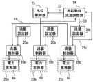
図2は、第1の実施の形態の給水制御装置7の一部のブロック図である。   FIG. 2 is a block diagram of a part of the water supply control device 7 according to the first embodiment.

給水制御装置7は、水位制御器15、水位設定器16を有している。また、3台の電力変換器6a,6b,6cに回転数指令信号8a,8b,8cを伝達する流量制御器19a,19b,19cを有している。また、それぞれの流量制御器19a,19b,19cに対応する流量設定器20a,20b,20cを有している。   The water supply control device 7 has a water level controller 15 and a water level setter 16. In addition, flow rate controllers 19a, 19b, and 19c that transmit rotation speed command signals 8a, 8b, and 8c to the three power converters 6a, 6b, and 6c are provided. Moreover, it has the flow volume setting device 20a, 20b, 20c corresponding to each flow volume controller 19a, 19b, 19c.

水位制御器15は、原子炉水位検出器9から原子炉水位信号12が、主蒸気流量検出器10から主蒸気流量信号13が、給水流量検出器11から原子炉給水流量信号14が、水位設定器16から原子炉水位設定信号17が伝達される。水位制御器15は、原子炉水位信号12、主蒸気流量信号13および原子炉給水流量信号14に基づいて演算を行い、さらにその演算結果を原子炉水位設定信号17と比較することにより、原子炉水位設定信号17に合うような給水流量指令信号18を出力する。   The water level controller 15 is configured to set the water level from the reactor water level detector 9 to the reactor water level signal 12, from the main steam flow rate detector 10 to the main steam flow rate signal 13, and from the feed water flow rate detector 11 to the reactor feed water flow rate signal 14. A reactor water level setting signal 17 is transmitted from the vessel 16. The water level controller 15 performs a calculation based on the reactor water level signal 12, the main steam flow signal 13, and the reactor feed water flow signal 14, and compares the calculation result with the reactor water level setting signal 17, thereby A water supply flow rate command signal 18 that matches the water level setting signal 17 is output.

流量制御器19a,19b,19cは、給水流量指令信号18、もしくは、流量設定器20a、20b、20cから伝達される流量設定信号21a,21b,21cによって、電力変換器6a,6b,6cに回転数指令信号8a,8b,8cを伝達する。このようにして、電力変換器6a,6b,6cの周波数を調節して電動機5a,5b,5cの速度、すなわち、給水ポンプ4a,4b,4cの速度を制御することにより、原子炉給水流量を制御する。   The flow rate controllers 19a, 19b, and 19c are rotated to the power converters 6a, 6b, and 6c by the feed water flow rate command signal 18 or the flow rate setting signals 21a, 21b, and 21c transmitted from the flow rate setting units 20a, 20b, and 20c. Number command signals 8a, 8b and 8c are transmitted. In this way, by adjusting the frequency of the power converters 6a, 6b, 6c to control the speed of the electric motors 5a, 5b, 5c, that is, the speed of the feed water pumps 4a, 4b, 4c, the reactor feed water flow rate is reduced. Control.

また、給水制御装置7は、3台の給水ポンプ4a,4b,4cを駆動する電動機5a,5b,5cに対応するトリップ判定回路22a,22b,22cを有している。トリップ判定回路22a,22b,22cは、回転数指令信号8a,8b,8cおよび電動機5a,5b,5cのモータ回転数信号26a,26b,26cに基づいて給水ポンプ4a,4b,4cのトリップを判定する。   The water supply control device 7 has trip determination circuits 22a, 22b, and 22c corresponding to the electric motors 5a, 5b, and 5c that drive the three water supply pumps 4a, 4b, and 4c. Trip determination circuits 22a, 22b and 22c determine trips of water supply pumps 4a, 4b and 4c based on rotation speed command signals 8a, 8b and 8c and motor rotation speed signals 26a, 26b and 26c of electric motors 5a, 5b and 5c. To do.

図3は、第1の実施の形態のトリップ判定回路22のブロック図である。なお、給水制御装置7は、3台の給水ポンプ4a,4b,4cに対応する3つのトリップ判定回路22a,22b,22cを有しているが、図3では、そのうちの1つの回路のみを示している。また、符号「a」、「b」および「c」は、それぞれ3台の給水ポンプに対応する機器、回路などであることを示しており、図3では符号「a」、「b」および「c」の記載を省略している。   FIG. 3 is a block diagram of the trip determination circuit 22 according to the first embodiment. The water supply control device 7 has three trip determination circuits 22a, 22b, and 22c corresponding to the three water supply pumps 4a, 4b, and 4c. FIG. 3 shows only one of them. ing. The symbols “a”, “b”, and “c” indicate devices, circuits, and the like that correspond to the three water supply pumps, respectively. In FIG. 3, the symbols “a”, “b”, and “c” The description of “c” is omitted.

トリップ判定回路22は、減算器27、閾値判定回路28とタイマー29を有している。トリップ判定回路22には、回転数指令信号8とモータ回転数信号26が入力され、減算器27は、これらの偏差をとる。閾値判定回路28は、この偏差が許容しうる値か否かを判定する。許容しうる値でなかった場合には、信号がタイマー29に出力される。タイマー29は、この信号が所定の時間以上継続した場合に、ポンプトリップ信号30を出力する。不要なトリップ判定を防止するために、タイマー29がポンプトリップ信号30を出力するまでの時間は電力変換器6cが再起動により復旧可能な時間よりも長く設定する。   The trip determination circuit 22 includes a subtractor 27, a threshold determination circuit 28, and a timer 29. The trip determination circuit 22 receives the rotation speed command signal 8 and the motor rotation speed signal 26, and the subtractor 27 takes these deviations. The threshold determination circuit 28 determines whether or not the deviation is an allowable value. If the value is not acceptable, a signal is output to the timer 29. The timer 29 outputs a pump trip signal 30 when this signal continues for a predetermined time or more. In order to prevent unnecessary trip determination, the time until the timer 29 outputs the pump trip signal 30 is set longer than the time that the power converter 6c can be recovered by restarting.

なお、本実施の形態では、トリップ判定回路22は、全ての給水ポンプ4a,4b,4cに対応して設置しているが、常用の給水ポンプ4a,4bにのみ対応して設置しておいてもよい。   In the present embodiment, the trip determination circuit 22 is installed corresponding to all the feed pumps 4a, 4b, 4c, but is installed corresponding to only the regular feed pumps 4a, 4b. Also good.

このように、本実施の形態の給水制御装置7では、回転数指令信号8とモータ回転数信号26とを比較し、偏差が大きい状態が継続した場合にポンプトリップと判定し、ポンプトリップ信号30を出力する。このため、電力変換器6a,6bの自己診断機能によらないで、電力変換器6a,6bが故障した際の給水不能状態を検出することが可能となり、バックアップの給水ポンプ4cを起動することが可能となる。これにより、原子炉水位低によってスクラムにいたる可能性を低減できる。またタイマー29を設けることにより、電力変換器6cが再起動することにより復帰可能な場合にまで、不要に給水ポンプをトリップさせることがない。   Thus, in the water supply control device 7 of the present embodiment, the rotation speed command signal 8 and the motor rotation speed signal 26 are compared, and when a large deviation continues, it is determined that the pump trip occurs, and the pump trip signal 30 Is output. For this reason, it becomes possible to detect the inability to supply water when the power converters 6a and 6b fail without depending on the self-diagnosis function of the power converters 6a and 6b, and the backup water supply pump 4c can be activated. It becomes possible. As a result, the possibility of reaching the scram due to the low reactor water level can be reduced. Further, by providing the timer 29, the water supply pump is not tripped unnecessarily until the power converter 6c can be restored by restarting.

図4は、第1の実施の形態のバックアップ起動回路23および制御切替器24の周辺のブロック図である。なお、給水制御装置7は、3台の給水ポンプ4a,4b,4cに対応する3つのバックアップ起動回路23a,23b,23cおよび制御切替器24a,24b,24cを有しているが、図4では、そのうちの1つずつを示している。また、符号「a」、「b」および「c」は、それぞれ3台の給水ポンプに対応する機器、回路などであることを示しており、図4では符号「a」、「b」および「c」の記載を省略している。   FIG. 4 is a block diagram of the periphery of the backup activation circuit 23 and the control switch 24 according to the first embodiment. The water supply control device 7 has three backup activation circuits 23a, 23b, 23c and control switchers 24a, 24b, 24c corresponding to the three water supply pumps 4a, 4b, 4c, but in FIG. , One of them is shown. The symbols “a”, “b”, and “c” indicate devices, circuits, and the like that correspond to the three water supply pumps, respectively. In FIG. 4, the symbols “a”, “b”, and “c” The description of “c” is omitted.

バックアップ起動回路23は、電力変換器6、電力変換器制御スイッチ31とバックアップ起動スイッチ32を有している。バックアップ起動回路23には、発電所の変圧母線から供給される、周波数が50Hzまたは60Hz程度の電源33が接続されている。   The backup activation circuit 23 includes a power converter 6, a power converter control switch 31, and a backup activation switch 32. A power source 33 having a frequency of about 50 Hz or about 60 Hz supplied from the transformer bus of the power plant is connected to the backup activation circuit 23.

ある給水ポンプが常用の給水ポンプ4a,4bとして運転される場合には、バックアップ起動回路23の電力変換器制御スイッチ31は入、バックアップ起動スイッチ32は切として、その給水ポンプを駆動する電動機5は電力変換器6により回転数制御される。   When a certain water supply pump is operated as a regular water supply pump 4a, 4b, the power converter control switch 31 of the backup activation circuit 23 is turned on, the backup activation switch 32 is turned off, and the electric motor 5 that drives the water supply pump is The rotational speed is controlled by the power converter 6.

一方、ある給水ポンプが予備の給水ポンプ4cとして使用される場合には、電力変換器制御スイッチ31が切、バックアップ起動スイッチ32が入として、その給水ポンプを駆動する電動機5は、電力変換器6を介さず、電源33により直接駆動される。   On the other hand, when a certain water supply pump is used as the spare water supply pump 4c, the power converter control switch 31 is turned off and the backup start switch 32 is turned on, and the electric motor 5 that drives the water supply pump is connected to the power converter 6 It is directly driven by the power source 33 without going through.

つまり、本実施の形態の給水制御装置7では、運転中の給水ポンプをトリップと判定した場合に、トリップしていない予備の給水ポンプ4cを駆動する電動機5cの回転数を増加させてトリップによる給水流量の低下を補償する。具体的には、予備の給水ポンプ4cは、バックアップ起動回路23によって、電源33を直接用いて急速起動され、電源33の電圧および周波数で運転される。つまり、大容量の電力変換器を設置することなく、急速に予備の給水ポンプを起動することができる。このように、電力変換器6の出力電流制限に制約されることなく急速起動が可能となるため、電力変換器6として最適な容量のものを選定することが可能となり、経済的である。   That is, in the water supply control device 7 of the present embodiment, when it is determined that the operating water supply pump is a trip, the number of rotations of the electric motor 5c that drives the non-tripped auxiliary water supply pump 4c is increased to supply water by the trip. Compensates for the decrease in flow rate. Specifically, the backup water supply pump 4 c is rapidly activated by the backup activation circuit 23 using the power supply 33 directly, and is operated at the voltage and frequency of the power supply 33. That is, it is possible to start the spare water supply pump rapidly without installing a large-capacity power converter. As described above, since rapid activation is possible without being restricted by the output current limitation of the power converter 6, it is possible to select a power converter 6 having an optimum capacity, which is economical.

制御切替器24は、バックアップ起動した予備の給水ポンプ4cに対応する電力変換器6cを制御する流量設定器20に対し、電源33で運転した場合の回転数に対応する定格流量設定信号35を出力する。給水ポンプの流量設定器20は、流量制御器19に対し、電源33で運転した場合の回転数に対応する流量設定信号を出力するよう設定される。   The control switching unit 24 outputs a rated flow rate setting signal 35 corresponding to the number of revolutions when the power source 33 is operated to the flow rate setting unit 20 that controls the power converter 6c corresponding to the backup water pump 4c that has been backed up. To do. The flow rate setting device 20 of the feed water pump is set to output a flow rate setting signal corresponding to the number of revolutions when operated by the power source 33 to the flow rate controller 19.

また、制御切替器24は、切替指令信号34を出力して、バックアップ起動スイッチ32を切にした後、電力変換器制御スイッチ31を入にすることによって、予備の給水ポンプの駆動電源を電源33から電力変換器6に切り替える。電動機5の回転数は、切替により一旦減少する。その後、給水ポンプの流量制御器19から伝達される電源33で運転した場合の回転数に対応する回転数指令信号に従い、切替前の回転数に復帰する。   Further, the control switch 24 outputs a switch command signal 34, turns off the backup start switch 32, and then turns on the power converter control switch 31 to turn on the drive power source of the spare water pump. To the power converter 6. The number of revolutions of the electric motor 5 temporarily decreases by switching. Then, according to the rotation speed command signal corresponding to the rotation speed when operating with the power supply 33 transmitted from the flow rate controller 19 of the feed water pump, the rotation speed before switching is restored.

なお、本実施の形態では、バックアップ起動回路23および制御切替器24は、全ての給水ポンプ4a,4b,4cに対応して設置しているが、予備の給水ポンプ4cにのみ対応して設置しておいてもよい。   In this embodiment, the backup activation circuit 23 and the control switch 24 are installed corresponding to all the water supply pumps 4a, 4b, 4c, but are installed only corresponding to the spare water supply pump 4c. You may keep it.

図5は、第1の実施の形態の流量調整器25の周辺のブロック図である。   FIG. 5 is a block diagram of the periphery of the flow rate regulator 25 according to the first embodiment.

ここでは、符号4bで示す給水ポンプがトリップし、符号4cで示す予備のポンプがバックアップ起動した場合について説明する。   Here, the case where the feed water pump indicated by reference numeral 4b trips and the backup pump indicated by reference numeral 4c starts backup will be described.

流量調整器25は、バックアップ起動した給水ポンプ4cに対応する電力変換器6cを制御する流量制御器19cに対する流量要求信号を一定の割合で減少させる減少信号36を出力するとともに、減少信号36と正負逆の補正信号37を水位制御器15に出力する。また、流量調整器25は、水位制御器15からの給水流量指令信号18と流量設定信号21cの偏差をとる。この偏差が許容範囲内の場合、流量調整器25は減少信号36および補正信号37の出力を停止するとともに、流量制御器19cへの入力を流量設定信号21cから給水流量指令信号18へと変更する。バックアップ起動した予備の給水ポンプ4cの流量を減少させながら他の給水ポンプの流量を増加させるよう制御される。   The flow rate regulator 25 outputs a decrease signal 36 for decreasing the flow rate request signal to the flow rate controller 19c that controls the power converter 6c corresponding to the backup activated feed water pump 4c at a constant rate, and is positive and negative with the decrease signal 36. A reverse correction signal 37 is output to the water level controller 15. Further, the flow rate regulator 25 takes the deviation between the feed water flow rate command signal 18 from the water level controller 15 and the flow rate setting signal 21c. When this deviation is within the allowable range, the flow rate regulator 25 stops the output of the decrease signal 36 and the correction signal 37 and changes the input to the flow rate controller 19c from the flow rate setting signal 21c to the feed water flow rate command signal 18. . Control is performed to increase the flow rates of the other feed water pumps while decreasing the flow rate of the backup feed water pump 4c that has been started up.

予備の給水ポンプ4cは、定格回転数による運転から電力変換器6cによる制御運転に自動的に移行し、さらに自動的に給水流量指令信号18に従った回転数に制御されるため、原子炉給水流量を安定して供給し続けることができる。なお、運転員の操作の負担も小さい。   The spare feed water pump 4c automatically shifts from the operation at the rated rotation speed to the control operation by the power converter 6c and is automatically controlled at the rotation speed in accordance with the feed water flow command signal 18, so that the reactor water supply A flow rate can be stably supplied. In addition, the operation burden on the operator is small.

このように本実施の形態の給水制御装置によれば、電力変換器の自己診断機能によらず電力変換器が故障した際の給水不能状態を検出して、バックアップの給水ポンプを起動することができる。このため、原子炉水位低によるスクラムの可能性を低減できる。また、電力変換器による起動に比べて、予備の給水ポンプを急速にバックアップ起動することが可能となり、原子炉水位低によるスクラムの可能性を低減できる。また、電力変換器の出力電流制限に制約されることなく急速起動が可能となるため、電力供給装置として最適な容量のものを選定することが可能となり、経済的である。   Thus, according to the water supply control device of the present embodiment, the backup water pump can be activated by detecting the inability to supply water when the power converter has failed regardless of the self-diagnosis function of the power converter. it can. For this reason, the possibility of scram due to low reactor water level can be reduced. In addition, the backup water pump can be quickly backed up as compared with the power converter, and the possibility of scram due to low reactor water level can be reduced. In addition, since rapid start-up is possible without being restricted by the output current limit of the power converter, it is possible to select a power supply device having an optimum capacity, which is economical.

[第2の実施の形態]
図6は、本発明に係る第2の実施の形態の原子力発電プラントの系統図である。
[Second Embodiment]
FIG. 6 is a system diagram of the nuclear power plant according to the second embodiment of the present invention.

本実施の形態の給水制御装置は、第1の実施の形態の給水制御装置からトリップ判定回路を省いたものである。   The water supply control device according to the present embodiment is obtained by omitting the trip determination circuit from the water supply control device according to the first embodiment.

本実施の形態でも、運転中の給水ポンプを、たとえば電力変換器自身の自己診断によってトリップと判定した場合、予備の給水ポンプはバックアップ起動回路により電源33(図4)にて急速起動され、電源33(図4)の電圧および周波数で運転される。このため、常用の給水ポンプが1台トリップした場合に、電力変換器による起動に比べて、予備の給水ポンプを急速にバックアップ起動することが可能となり、給水ポンプトリップ時に原子炉水位低によるスクラムの可能性を低減できる。また、電力変換器の出力電流制限に制約されることなく急速起動が可能となるため、電力供給装置として最適な容量のものを選定することが可能となり、経済的である。   Also in this embodiment, when it is determined that the water pump being operated is tripped by, for example, self-diagnosis of the power converter itself, the backup water pump is rapidly activated by the power source 33 (FIG. 4) by the backup activation circuit. It is operated at a voltage and frequency of 33 (FIG. 4). For this reason, when one regular feedwater pump trips, it is possible to start up a backup feedwater pump more quickly than when a power converter is started. The possibility can be reduced. In addition, since rapid start-up is possible without being restricted by the output current limit of the power converter, it is possible to select a power supply device having an optimum capacity, which is economical.

また、電動機5の回転数は、切替により一旦減少した後、給水ポンプの流量制御器19(図4)から伝達される電源33(図4)で運転した場合の回転数に対応する回転数要求信号に従い、切替前の回転数に復帰する。起動した予備の給水ポンプは、定格回転数による運転から電力変換器による制御運転に自動的に移行し、さらに自動的に給水制御信号に従った回転数に制御されるため、原子炉給水流量を安定して供給し続けることができる。   Moreover, after the rotation speed of the electric motor 5 is once reduced by switching, the rotation speed request corresponding to the rotation speed when the motor 5 is operated by the power supply 33 (FIG. 4) transmitted from the flow rate controller 19 (FIG. 4) of the feed water pump. According to the signal, it returns to the rotation speed before switching. The activated backup water pump automatically shifts from the operation at the rated speed to the control operation by the power converter and is automatically controlled at the speed according to the feed water control signal. It can continue to be supplied stably.

また、バックアップ起動した給水ポンプの流量を減少させながら他のポンプの流量を増加させるよう制御される。また、あらかじめ運転側のポンプの給水流量指令をバックアップ側の減少分に対応した増分の割合で増加させることにより、全給水流量が変動せず、原子炉水位の変動を抑えることができる。   In addition, control is performed to increase the flow rate of the other pumps while decreasing the flow rate of the backup water supply pump. Further, by increasing the feed water flow command of the pump on the operation side in advance at a rate corresponding to the decrease on the backup side, the total feed water flow rate does not fluctuate and fluctuations in the reactor water level can be suppressed.

[第3の実施の形態]
図7は、本発明に係る第3の実施の形態の原子力発電プラントの系統図である。
[Third Embodiment]
FIG. 7 is a system diagram of a nuclear power plant according to the third embodiment of the present invention.

本実施の形態の給水制御装置7は、第1の実施の形態からバックアップ起動回路、制御切替器および流量調整器を省いたものである。   The water supply control device 7 according to the present embodiment is obtained by omitting the backup activation circuit, the control switching device, and the flow rate regulator from the first embodiment.

この実施の形態でも、回転数指令信号8a,8b,8cと電動機5a,5b,5cの回転数を比較し、偏差が大きい状態が継続した場合にポンプトリップと判定し、ポンプトリップ信号30を出力する。このため、電力変換器6a,6b,6cの自己診断機能によらず電力変換器6a,6b,6cが故障した際の給水不能状態を検出することが可能であり、バックアップの給水ポンプ4cを起動することができる。したがって、原子炉水位低によるスクラムの可能性を低減できる。またタイマー29を設けることにより、電力変換器の自己診断により復帰可能な場合に不要に給水ポンプをトリップさせることがない。   Also in this embodiment, the rotational speed command signals 8a, 8b, and 8c are compared with the rotational speeds of the electric motors 5a, 5b, and 5c, and when a large deviation continues, it is determined that the pump trip occurs and the pump trip signal 30 is output. To do. For this reason, it is possible to detect the inability to supply water when the power converters 6a, 6b, 6c fail, regardless of the self-diagnosis function of the power converters 6a, 6b, 6c, and start the backup water pump 4c. can do. Therefore, the possibility of scram due to low reactor water level can be reduced. Further, by providing the timer 29, the water supply pump is not tripped unnecessarily when it can be recovered by self-diagnosis of the power converter.

[第4の実施の形態]
図8は、本発明に係る第4の実施の形態の原子力発電プラントの系統図である。
[Fourth Embodiment]
FIG. 8 is a system diagram of a nuclear power plant according to the fourth embodiment of the present invention.

本実施の形態の原子力発電プラントでは、それぞれ全給水量の50%以上の容量を有する給水ポンプ4a,4b,4cの3台全てが、常用給水ポンプとして運転される。つまり、通常運転時には、給水ポンプ4a,4b,4cのそれぞれが、全給水容量の3分の1ずつを給水する。   In the nuclear power plant according to the present embodiment, all three water supply pumps 4a, 4b, 4c each having a capacity of 50% or more of the total water supply amount are operated as regular water supply pumps. That is, during normal operation, each of the water supply pumps 4a, 4b, and 4c supplies one third of the total water supply capacity.

また、本実施の形態の給水制御装置7は、トリップ判定回路22、再起動時流量調整器54およびトリップ時制御器51を有している。給水制御装置7は、給水ポンプ4a,4b,4cを駆動する電動機5a,5b,5cからモータ回転数信号26a,26b,26cなどの信号を受け取って、電力変換器6a,6b,6cに、バックアップ起動回路23a,23b,23cを介して、回転数指令信号8a,8b,8cなどの信号を伝達する。   Further, the water supply control device 7 of the present embodiment includes a trip determination circuit 22, a restart flow rate adjuster 54, and a trip time controller 51. The water supply control device 7 receives signals such as motor rotation speed signals 26a, 26b, and 26c from the electric motors 5a, 5b, and 5c that drive the water supply pumps 4a, 4b, and 4c, and backs up the power converters 6a, 6b, and 6c. Signals such as rotation speed command signals 8a, 8b, and 8c are transmitted via the start circuits 23a, 23b, and 23c.

図9は、本実施の形態の給水制御装置の一部のブロック図である。   FIG. 9 is a block diagram of a part of the water supply control device of the present embodiment.

給水制御装置7は、水位制御器15、水位設定器16およびトリップ時制御器51を有している。また、3台の電力変換器6a,6b,6cに回転数指令信号8a,8b,8cを伝達する流量制御器19a,19b,19cを有している。また、それぞれの流量制御器19a,19b,19cに対応する流量設定器20a,20b,20cを有している。また、給水制御装置7は、第1の実施の形態と同様に、3台の給水ポンプ4a,4b,4cを駆動する電動機5a,5b,5cに対応するトリップ判定回路22a,22b,22cを有している(図3参照)。   The water supply control device 7 includes a water level controller 15, a water level setter 16, and a trip time controller 51. In addition, flow rate controllers 19a, 19b, and 19c that transmit rotation speed command signals 8a, 8b, and 8c to the three power converters 6a, 6b, and 6c are provided. Moreover, it has the flow volume setting device 20a, 20b, 20c corresponding to each flow volume controller 19a, 19b, 19c. The water supply control device 7 has trip determination circuits 22a, 22b, and 22c corresponding to the electric motors 5a, 5b, and 5c that drive the three water supply pumps 4a, 4b, and 4c, as in the first embodiment. (See FIG. 3).

水位制御器15は、原子炉水位検出器9から原子炉水位信号12が、主蒸気流量検出器10から主蒸気流量信号13が、給水流量検出器11から原子炉給水流量信号14が、水位設定器16から原子炉水位設定信号17が伝達される。また、トリップ時制御器51は、何らかの理由で給水ポンプ4a,4b,4cのうちの1台がトリップした際にこれを検出し、水位制御器15にトリップ時制御信号52を出力する。   The water level controller 15 is configured to set the water level from the reactor water level detector 9 to the reactor water level signal 12, from the main steam flow rate detector 10 to the main steam flow rate signal 13, and from the feed water flow rate detector 11 to the reactor feed water flow rate signal 14. A reactor water level setting signal 17 is transmitted from the vessel 16. The trip time controller 51 detects when one of the water supply pumps 4 a, 4 b, 4 c trips for some reason, and outputs a trip time control signal 52 to the water level controller 15.

水位制御器15は、原子炉水位信号12、主蒸気流量信号13および原子炉給水流量信号14に基づいて演算を行い、さらにその演算結果を原子炉水位設定信号17と比較することにより、原子炉水位設定信号17に合うような給水流量指令信号18を出力する。   The water level controller 15 performs a calculation based on the reactor water level signal 12, the main steam flow signal 13, and the reactor feed water flow signal 14, and compares the calculation result with the reactor water level setting signal 17, thereby A water supply flow rate command signal 18 that matches the water level setting signal 17 is output.

また、給水ポンプ4a,4b,4cのうちの1台がトリップした際には、水位制御器15は、トリップ時制御信号52に基づいて給水流量指令信号18を出力する。これにより給水流量指令信号18が増加し、トリップしていない他の給水ポンプを駆動する電動機の回転数を増加させてトリップによる給水流量の低下を補償する。具体的には、トリップしていない運転中の給水ポンプの流量制御器19の設定が増加する。以下の説明では、給水ポンプ4cがトリップした場合について説明するが、他の給水ポンプ4a,4bがトリップした場合でも、同様である。   Further, when one of the feed water pumps 4 a, 4 b, 4 c trips, the water level controller 15 outputs a feed water flow rate command signal 18 based on the trip time control signal 52. As a result, the feed water flow command signal 18 increases, and the rotational speed of the electric motor that drives the other feed water pumps that have not tripped is increased to compensate for the drop in the feed water flow due to the trip. Specifically, the setting of the flow controller 19 of the feed water pump that is not tripped is increased. In the following description, the case where the feed water pump 4c trips will be described, but the same applies to the case where the other feed water pumps 4a and 4b trip.

図10は、本実施の形態の再起動時流量調整器のブロック図である。   FIG. 10 is a block diagram of the restart flow rate regulator of the present embodiment.

再起動時流量調整器54は、トリップ後再起動した給水ポンプ4cに対応する電力変換装置6cを制御する流量制御器19cに対する流量要求信号を一定の割合で増加させる増加信号53を出力する。また、増加信号53と正負逆の補正信号37を水位制御器15に出力する。さらに、水位制御器15からの給水流量指令信号18と流量設定信号21cの偏差をとり、偏差が許容値内の場合、増加信号53および補正信号37の出力を停止する。また、流量制御器19cへの入力を流量設定信号21bから給水流量指令信号18へと変更する。   The restart flow rate adjuster 54 outputs an increase signal 53 that increases the flow rate request signal to the flow rate controller 19c that controls the power converter 6c corresponding to the water supply pump 4c restarted after the trip at a constant rate. Further, the increase signal 53 and the positive / negative correction signal 37 are output to the water level controller 15. Further, the deviation between the water supply flow rate command signal 18 and the flow rate setting signal 21c from the water level controller 15 is taken, and when the deviation is within the allowable value, the output of the increase signal 53 and the correction signal 37 is stopped. Further, the input to the flow rate controller 19c is changed from the flow rate setting signal 21b to the feed water flow rate command signal 18.

このような給水制御装置7では、回転数指令信号とモータ回転数を比較し、偏差が大きい状態が継続した場合にポンプトリップと判定し、ポンプトリップ信号30を出力する。また、運転中の給水ポンプをトリップと判定した場合、トリップと判定されていない残り2台の給水ポンプの給水指令信号を増加させる。さらに、トリップ後再起動した給水ポンプの流量を増加させながら他のポンプの流量を減少させるよう制御する。   In such a water supply control device 7, the rotational speed command signal and the motor rotational speed are compared, and when the state where the deviation is large continues, it is determined that the pump is tripped, and the pump trip signal 30 is output. Moreover, when it determines with the water pump in driving | operation being a trip, the water supply command signal of the remaining two water pumps which are not determined to be a trip is increased. Furthermore, it controls to decrease the flow rate of the other pumps while increasing the flow rate of the feed water pump restarted after the trip.

したがって、電力変換器の自己診断機能によらず給水不能状態を検出することが可能となる。このため、原子炉水位低によるスクラムをより確実に回避できる。またタイマー29を設けることにより、電力変換器が再起動することにより復帰可能な場合には、給水ポンプをトリップさせることがない。   Therefore, it becomes possible to detect the inability to supply water regardless of the self-diagnosis function of the power converter. For this reason, the scram caused by the low reactor water level can be avoided more reliably. Further, by providing the timer 29, when the power converter can be restored by restarting, the water supply pump is not tripped.

また、給水ポンプ4a,4b,4cのうちの1台がトリップした場合、トリップしていない給水ポンプの給水流量指令を増加させることにより、給水ポンプトリップ時の原子炉水位低によるスクラムを回避できる。   Further, when one of the feed water pumps 4a, 4b, 4c trips, a scram caused by a low reactor water level when the feed water pump trips can be avoided by increasing the feed water flow rate command of the feed water pump that has not tripped.

また、本実施の形態の原子力発電プラントでは、全数の給水ポンプ4a,4b,4cを常用の給水ポンプとしているため、このうちの1台がトリップした場合に、回転が停止している状態の給水ポンプを急速に起動する必要がない。このため、電力変換器の出力電流制限に制約されることなく電力供給装置として最適な容量のものを選定することが可能となり、経済的である。   Moreover, in the nuclear power plant of this Embodiment, since all the feed water pumps 4a, 4b, and 4c are regular feed water pumps, when one of them trips, the feed water is in a state where the rotation is stopped. There is no need to start the pump quickly. For this reason, it becomes possible to select a power supply device having an optimum capacity without being restricted by the output current limit of the power converter, which is economical.

また、再起動した給水ポンプは、自動的に給水制御信号に従った回転数に制御されるため、原子炉給水流量を安定して供給し続けることができる。さらに、あらかじめ運転側のポンプの給水流量指令をトリップ後再起動した給水ポンプの増加分に対応した割合で減少させることにより、全給水流量は変動せず、原子炉水位の変動を抑えることができる。   Moreover, since the restarted feed water pump is automatically controlled to the rotation speed according to a feed water control signal, it can continue supplying the reactor feed water flow volume stably. Furthermore, by reducing the feed water flow command of the pump on the operation side at a rate corresponding to the increase of the feed water pump that has been restarted after a trip, the total feed water flow does not fluctuate and fluctuations in the reactor water level can be suppressed. .

運転中に給水ポンプのうち1台の保守点検が必要となった場合も、残り2台の給水ポンプが運転することにより定格給水流量を維持することが可能である。また、流量調整回路の機能によって速やかに通常状態に復旧可能であり、保守性も高い。   Even when one of the water supply pumps needs to be inspected during operation, the rated water supply flow rate can be maintained by operating the remaining two water supply pumps. Moreover, the normal state can be quickly restored by the function of the flow rate adjustment circuit, and the maintainability is also high.

[第5の実施の形態]
図11は、本発明に係る第5の実施の形態における原子力発電プラントの系統図である。
[Fifth Embodiment]
FIG. 11 is a system diagram of a nuclear power plant according to the fifth embodiment of the present invention.

本実施の形態の給水制御装置7は、第4の実施の形態の給水制御装置7からトリップ判定回路およびトリップ時制御器51を削除したものである。このような給水制御装置7であっても、第4の実施の形態の給水制御装置7と同様に、トリップ後再起動した給水ポンプ4cの流量を増加させながら他の給水ポンプ4a,4bの流量を減少させるよう制御される。   The water supply control device 7 of the present embodiment is obtained by deleting the trip determination circuit and the trip time controller 51 from the water supply control device 7 of the fourth embodiment. Even with such a water supply control device 7, as with the water supply control device 7 of the fourth embodiment, the flow rates of the other water supply pumps 4a and 4b are increased while increasing the flow rate of the water supply pump 4c restarted after the trip. It is controlled to decrease.

このような給水制御装置7を用いても、トリップ後に再起動した給水ポンプ4cは、最低回転数による運転から電力変換器6cによる制御運転に自動的に移行する。さらに、自動的に給水流量指令信号18に従った回転数に制御されるため、適切な給水流量を安定して供給し続けることができる。   Even when such a water supply control device 7 is used, the water supply pump 4c restarted after the trip automatically shifts from the operation at the minimum rotational speed to the control operation by the power converter 6c. Furthermore, since the rotation speed is automatically controlled according to the feed water flow command signal 18, an appropriate feed water flow can be stably supplied.

また、運転中の給水ポンプ4a,4bの給水流量指令信号18を、トリップ後再起動したポンプ4cの増加分に対応した割合で減少させることにより、全給水流量が変動せず、原子炉水位の変動を抑えることができる。運転中に給水ポンプ4a,4b,4cのうち1台の保守点検が必要となった場合も、残り2台の給水ポンプが運転することにより定格給水流量を維持することが可能である。さらに、再起動時流量調整器54の機能によって速やかに通常状態に復旧可能であり、保守性が高い。   Further, by reducing the feed water flow rate command signal 18 of the feed water pumps 4a and 4b during operation at a rate corresponding to the increase in the pump 4c restarted after the trip, the total feed water flow rate does not fluctuate and the reactor water level Variation can be suppressed. Even when one of the water supply pumps 4a, 4b, and 4c needs to be inspected during operation, the rated water supply flow rate can be maintained by operating the remaining two water supply pumps. Further, the normal state can be quickly restored by the function of the flow rate regulator 54 at the time of restart, and the maintainability is high.

[第6の実施の形態]
図12は、本発明に係る第6の実施の形態における原子力発電プラントの系統図である。
[Sixth Embodiment]
FIG. 12 is a system diagram of a nuclear power plant according to the sixth embodiment of the present invention.

本実施の形態の原子力発電プラントは、第4の実施の形態の原子力発電プラントに、給水ポンプ4dおよび、これを駆動する電動機5d、電力変換器6d、流量制御器19およびトリップ判定回路22を追加したものである。この給水ポンプ4dは、他の給水ポンプ4a,4b,4cと並列に設けられている。4台の給水ポンプ4a,4b,4c,4dは、それぞれ原子炉容器1への全給水量の3分の1以上の容量を有している。通常運転時には、4台の給水ポンプ4a,4b,4c,4dは全て常用給水ポンプとして運転され、1台の給水ポンプあたり原子炉容器1への全給水量の4分の1ずつを給水する。   In the nuclear power plant of the present embodiment, a feed water pump 4d, an electric motor 5d that drives the water pump, a power converter 6d, a flow rate controller 19, and a trip determination circuit 22 are added to the nuclear power plant of the fourth embodiment. It is a thing. This water supply pump 4d is provided in parallel with the other water supply pumps 4a, 4b, 4c. Each of the four water supply pumps 4a, 4b, 4c, and 4d has a capacity of one third or more of the total water supply amount to the reactor vessel 1. During normal operation, the four water supply pumps 4a, 4b, 4c, and 4d are all operated as regular water supply pumps, and supply one quarter of the total amount of water supplied to the reactor vessel 1 per one water supply pump.

常用給水ポンプが3台の場合には、給水ポンプの1台がトリップした場合は、他の給水ポンプの給水流量は全給水流量の1/3から1/2に増加されなければならない。しかし、本実施の形態の原子力発電プラントでは、給水ポンプ4a,4b,4c,4dの1台がトリップした場合に、他の給水ポンプの給水流量は全給水流量の1/4から1/3に増加されればよい。   If there are three regular feed pumps, and one of the feed pumps trips, the feed rate of the other feed pumps must be increased from 1/3 to 1/2 of the total feed rate. However, in the nuclear power plant of this embodiment, when one of the feed water pumps 4a, 4b, 4c, 4d trips, the feed water flow rate of the other feed water pumps is reduced from 1/4 to 1/3 of the total feed water flow rate. It only has to be increased.

このため、給水ポンプのトリップ時における給水流量は、速やかに定格流量に戻る。また、給水ポンプ4a,4b,4c,4dの1台がトリップした場合の、電動機5a,5b,5c,5dおよび電力変換器6a,6b,6c,6dの負荷も小さくなる。このため、電力変換器の出力電流制限に制約されることなく電力供給装置として最適な容量のものを選定することが可能となり、経済的である。   For this reason, the water supply flow rate at the time of trip of the water supply pump quickly returns to the rated flow rate. Further, when one of the water supply pumps 4a, 4b, 4c, 4d trips, the load on the electric motors 5a, 5b, 5c, 5d and the power converters 6a, 6b, 6c, 6d is also reduced. For this reason, it becomes possible to select a power supply device having an optimum capacity without being restricted by the output current limit of the power converter, which is economical.

[その他の実施の形態]
なお、以上の説明は単なる例示であり、本発明は上述の各実施の形態に限定されず、様々な形態で実施することができる。たとえば、上述の実施の形態は、沸騰水型原子力発電プラントを例として説明しているが、他の形式の原子力発電プラントにも適用可能である。また、各実施の形態の特徴を組み合わせて実施することもできる。
[Other embodiments]
The above description is merely an example, and the present invention is not limited to the above-described embodiments, and can be implemented in various forms. For example, although the above-described embodiment has been described by taking a boiling water nuclear power plant as an example, it can also be applied to other types of nuclear power plants. Moreover, it can also implement combining the characteristic of each embodiment.

本発明に係る第1の実施の形態の原子力発電プラントの系統図である。1 is a system diagram of a nuclear power plant according to a first embodiment of the present invention. 本発明に係る第1の実施の形態の給水制御装置の一部のブロック図である。It is a partial block diagram of the water supply control apparatus of 1st Embodiment which concerns on this invention. 本発明に係る第1の実施の形態のトリップ判定回路のブロック図である。1 is a block diagram of a trip determination circuit according to a first embodiment of the present invention. 本発明に係る第1の実施の形態のバックアップ起動回路および制御切替器の周辺のブロック図である。It is a block diagram of the periphery of the backup start-up circuit and the control switch of the first embodiment according to the present invention. 本発明に係る第1の実施の形態の流量調整器の周辺のブロック図である。It is a block diagram of the circumference | surroundings of the flow regulator of 1st Embodiment which concerns on this invention. 本発明に係る第2の実施の形態の原子力発電プラントの系統図である。It is a systematic diagram of the nuclear power plant of 2nd Embodiment which concerns on this invention. 本発明に係る第3の実施の形態の原子力発電プラントの系統図である。It is a systematic diagram of the nuclear power plant of 3rd Embodiment which concerns on this invention. 本発明に係る第4の実施の形態の原子力発電プラントの系統図である。It is a systematic diagram of the nuclear power plant of 4th Embodiment which concerns on this invention. 本発明に係る第4の実施の形態の給水制御装置の一部のブロック図である。It is a partial block diagram of the water supply control apparatus of 4th Embodiment which concerns on this invention. 本発明に係る第4の実施の形態の再起動時流量調整器のブロック図である。It is a block diagram of the flow regulator at the time of restart of 4th Embodiment concerning this invention. 本発明に係る第5の実施の形態の原子力発電プラントの系統図である。It is a systematic diagram of the nuclear power plant of 5th Embodiment which concerns on this invention. 本発明に係る第6の実施の形態の原子力発電プラントの系統図である。It is a systematic diagram of the nuclear power plant of 6th Embodiment which concerns on this invention.

符号の説明Explanation of symbols

1…原子炉容器、2…発電タービン、3…復水器、4,4a,4b,4c,4d…給水ポンプ、5,5a,5b,5c,5d…電動機、6,6a,6b,6c,6d…電力変換器、7…給水制御装置、8,8a,8b,8c,8d…回転数指令信号、9…原子炉水位検出器、10…主蒸気流量検出器、11…給水流量検出器、12…原子炉水位信号、13…主蒸気流量信号、14…原子炉給水流量信号、15…水位制御器、16…水位設定器、17…原子炉水位設定信号、18…給水流量指令信号、19,19a,19b,19c…流量制御器、20,20a,20b,20c…流量設定器、21,21a,21b,21c…流量設定信号、22,22a,22b,22c…トリップ判定回路、23,23a,23b,23c,23d…バックアップ起動回路、24…制御切替器、25…流量調整器、26,26a,26b,26c,26d…モータ回転数信号、27…減算器、28…閾値判定回路、29…タイマー、30…ポンプトリップ信号、31…電力変換器制御スイッチ、32…バックアップ起動スイッチ、33…電源、34…切替指令信号、35…定格流量設定信号、36…減少信号、37…補正信号、40…主蒸気配管、41…給水配管、51…トリップ時制御器、52…トリップ時制御信号、53…増加信号、54…再起動時流量調整器 DESCRIPTION OF SYMBOLS 1 ... Reactor vessel, 2 ... Power generation turbine, 3 ... Condenser, 4, 4a, 4b, 4c, 4d ... Feed water pump, 5, 5a, 5b, 5c, 5d ... Electric motor, 6, 6a, 6b, 6c, 6 ... Power converter, 7 ... Feed water control device, 8, 8a, 8b, 8c, 8d ... Revolution command signal, 9 ... Reactor water level detector, 10 ... Main steam flow detector, 11 ... Feed water flow detector, DESCRIPTION OF SYMBOLS 12 ... Reactor water level signal, 13 ... Main steam flow signal, 14 ... Reactor feed water flow signal, 15 ... Water level controller, 16 ... Water level setter, 17 ... Reactor water level set signal, 18 ... Feed water flow command signal, 19 , 19a, 19b, 19c ... Flow rate controller, 20, 20a, 20b, 20c ... Flow rate setter, 21, 21a, 21b, 21c ... Flow rate setting signal, 22, 22a, 22b, 22c ... Trip determination circuit, 23, 23a , 23b, 23c, 23d ... Up start circuit, 24 ... control switch, 25 ... flow rate regulator, 26, 26a, 26b, 26c, 26d ... motor speed signal, 27 ... subtractor, 28 ... threshold judgment circuit, 29 ... timer, 30 ... pump trip Signal 31, power converter control switch 32, backup start switch 33, power source 34, switching command signal 35, rated flow rate setting signal 36, decrease signal 37, correction signal 40, main steam pipe 41 ... Water supply piping, 51 ... Trip controller, 52 ... Trip control signal, 53 ... Increase signal, 54 ... Restart flow rate adjuster

Claims (9)

原子炉で発生した熱により蒸気を発生させる原子力蒸気供給システムに水を供給する3台以上の給水ポンプと、その給水ポンプを駆動する電動機と、この電動機に接続された電力変換器とを備えた原子力発電プラントの給水制御装置において、検出された前記原子力発電プラントの状態を示す量、および、前記原子力蒸気供給システムの水位の設定値に基づいて、前記原子力蒸気供給システムへの給水流量を計算し、給水流量指令信号として出力する水位制御器と、前記給水流量指令信号に基づいて、前記電動機の回転数指令信号を生成する流量制御器と、前記給水ポンプのうちの1台がトリップした場合に、トリップしていない前記給水ポンプのうち少なくとも1台を駆動する前記電動機の回転数を増加させるトリップ補償手段と、を有することを特徴とする給水制御装置。   Three or more water supply pumps that supply water to a nuclear steam supply system that generates steam by heat generated in the nuclear reactor, an electric motor that drives the water supply pump, and a power converter connected to the electric motor In a water supply control device for a nuclear power plant, a feed water flow rate to the nuclear steam supply system is calculated based on the detected amount indicating the state of the nuclear power plant and a set value of the water level of the nuclear steam supply system. A water level controller that outputs a feed water flow command signal, a flow controller that generates a rotation speed command signal of the electric motor based on the feed water flow command signal, and one of the feed pumps trips. And trip compensation means for increasing the number of revolutions of the electric motor that drives at least one of the water supply pumps that have not tripped. Water supply control apparatus, characterized in that. 前記トリップ補償手段は、前記回転数指令信号が示す回転数と前記電動機の回転数との偏差が所定の差以上の状態が所定の時間経過した場合に前記給水ポンプはトリップしていると判定するトリップ判定回路を備える、ことを特徴とする請求項1に記載の給水制御装置。   The trip compensation means determines that the water supply pump is tripped when a predetermined time has elapsed when a deviation between the rotation speed indicated by the rotation speed command signal and the rotation speed of the electric motor exceeds a predetermined difference. The water supply control device according to claim 1, further comprising a trip determination circuit. 前記給水ポンプのうちの少なくとも1台は、通常時に運転されずに待機する予備給水ポンプであって、前記トリップ補償手段は、前記給水ポンプのうちの1台がトリップした場合に前記予備給水ポンプを駆動する前記電動機を電圧および周波数が一定の電源に直結して起動するバックアップ起動回路とを備える、ことを特徴とする請求項1または請求項2に記載の給水制御装置。   At least one of the water supply pumps is a standby water supply pump that stands by without being operated in a normal state, and the trip compensation means turns the spare water supply pump on when one of the water supply pumps trips. The water supply control device according to claim 1, further comprising a backup activation circuit that activates the electric motor to be driven by being directly connected to a power source having a constant voltage and frequency. 前記トリップ補償手段は、前記予備給水ポンプが起動してから所定の時間が経過した後に前記予備給水ポンプを駆動する電動機を前記電源から切り離し前記電力変換器に接続する制御切替器、を備えることを特徴とする請求項3記載の給水制御装置。   The trip compensation means includes a control switch that disconnects an electric motor that drives the auxiliary water supply pump from the power source and connects the electric power converter after a predetermined time has elapsed since the auxiliary water supply pump is activated. The water supply control device according to claim 3, wherein: 前記トリップ補償手段は、前記予備給水ポンプの回転数が時間の経過に伴って減少するように前記予備給水ポンプを駆動する電動機の回転数を変化させる流量調整器を備え、前記水位制御器は、前記予備給水ポンプの回転数の減少に伴う給水流量の変化量を補うように前記給水ポンプの回転数を変化させる指令を出力するものである、ことを特徴とする請求項4記載の給水制御装置。   The trip compensation means includes a flow rate regulator that changes the rotational speed of an electric motor that drives the preliminary feed water pump so that the rotational speed of the preliminary feed pump decreases with time, and the water level controller includes: 5. The water supply control device according to claim 4, wherein a command for changing the rotation speed of the feed water pump is output so as to compensate for a change amount of the feed water flow rate accompanying a decrease in the rotation speed of the preliminary feed water pump. . 全ての前記給水ポンプは通常時に運転される常用給水ポンプであって、前記トリップ補償手段は、前記給水ポンプのうちの1台がトリップした場合に前記給水流量指令信号が示す前記給水流量を増加させるトリップ時制御信号を前記水位制御器に伝達するトリップ時制御器を備えることを特徴とする請求項1または請求項2に記載の給水制御装置。   All the water supply pumps are service water pumps operated at normal times, and the trip compensation means increases the water supply flow rate indicated by the water supply flow rate command signal when one of the water supply pumps trips. The water supply control device according to claim 1, further comprising a trip time controller that transmits a trip time control signal to the water level controller. トリップした前記給水ポンプを再起動した際に、この給水ポンプに対応する前記流量制御器に単位時間あたり所定の割合で増加する前記給水流量指令信号を伝達し、前記水位制御器に前記給水流量を単位時間あたり前記所定の割合で減少させる補正信号を伝達する再起動時流量調整器を有することを特徴とする請求項6に記載の給水制御装置。   When the tripped feedwater pump is restarted, the feedwater flow command signal increasing at a predetermined rate per unit time is transmitted to the flow rate controller corresponding to the feedwater pump, and the feedwater flow rate is supplied to the water level controller. The water supply control device according to claim 6, further comprising a restart-time flow rate regulator that transmits a correction signal that decreases at the predetermined rate per unit time. 原子炉で発生した熱により蒸気を発生させる原子力蒸気供給システムと、前記原子力蒸気供給システムから供給される蒸気によって駆動される発電タービンと、前記発電タービンを駆動した蒸気を凝縮する復水器と、前記復水器で凝縮されて生成された水を前記原子力蒸気供給システムに供給する複数の給水ポンプと、検出された前記原子力発電プラントの状態を示す量、および、前記原子力蒸気供給システムの水位の設定値に基づいて、前記原子力蒸気供給システムへの給水流量を計算し、給水流量指令信号として出力する水位制御器と、前記給水流量指令信号に基づいて、前記電動機の回転数指令信号を生成する流量制御器と、前記給水ポンプのうちの1台がトリップした場合に、トリップしていない前記給水ポンプのうち少なくとも1台を駆動する前記電動機の回転数を増加させるトリップ補償手段と、を有することを特徴とする原子力発電プラント。   A nuclear steam supply system that generates steam by heat generated in a nuclear reactor, a power generation turbine that is driven by steam supplied from the nuclear steam supply system, a condenser that condenses the steam that has driven the power generation turbine, and A plurality of feed pumps for supplying water generated by condensation in the condenser to the nuclear steam supply system; an amount indicating the detected state of the nuclear power plant; and a water level of the nuclear steam supply system. A feed water flow rate to the nuclear steam supply system is calculated based on a set value, and a water level controller that outputs the feed water flow rate command signal and a rotation speed command signal for the electric motor are generated based on the feed water flow rate command signal. If one of the flow controller and one of the feed pumps trips, at least one of the feed pumps that have not tripped Nuclear power plant characterized by having an a trip compensating means for increasing the rotational speed of the electric motor that drives. 原子炉で発生した熱により蒸気を発生させる原子力蒸気供給システムに水を供給する3台以上の給水ポンプと、その給水ポンプを駆動する電動機と、この電動機に接続された電力変換器とを備えた原子力発電プラントの給水制御方法において、検出された前記原子力発電プラントの状態を示す量、および、前記原子力蒸気供給システムの水位の設定値に基づいて、前記原子力蒸気供給システムへの給水流量を計算し、給水流量指令信号として出力する工程と、前記給水流量指令信号に基づいて、前記電動機の回転数指令信号を生成する工程と、前記給水ポンプのうちの1台がトリップした場合に、トリップしていない前記給水ポンプのうち少なくとも1台を駆動する前記電動機の回転数を増加させる工程と、を有することを特徴とする給水制御方法。   Three or more water supply pumps that supply water to a nuclear steam supply system that generates steam by heat generated in the nuclear reactor, an electric motor that drives the water supply pump, and a power converter connected to the electric motor In the water supply control method for a nuclear power plant, the flow rate of the water supply to the nuclear steam supply system is calculated based on the detected amount indicating the state of the nuclear power plant and the set value of the water level of the nuclear steam supply system. A step of outputting as a feed water flow command signal, a step of generating a rotation speed command signal of the electric motor based on the feed water flow command signal, and a trip when one of the feed pumps trips. And increasing the number of rotations of the electric motor that drives at least one of the non-feeding water pumps. Method.
JP2007183096A 2006-07-28 2007-07-12 Water supply control device, nuclear power plant, and water supply control method Expired - Fee Related JP4709809B2 (en)

Priority Applications (1)

Application Number Priority Date Filing Date Title
JP2007183096A JP4709809B2 (en) 2006-07-28 2007-07-12 Water supply control device, nuclear power plant, and water supply control method

Applications Claiming Priority (3)

Application Number Priority Date Filing Date Title
JP2006205775 2006-07-28
JP2007183096A JP4709809B2 (en) 2006-07-28 2007-07-12 Water supply control device, nuclear power plant, and water supply control method

Publications (2)

Publication Number Publication Date
JP2008051805A true JP2008051805A (en) 2008-03-06
JP4709809B2 JP4709809B2 (en) 2011-06-29

Family

ID=39235971

Family Applications (1)

Application Number Title Priority Date Filing Date
JP2007183096A Expired - Fee Related JP4709809B2 (en) 2006-07-28 2007-07-12 Water supply control device, nuclear power plant, and water supply control method

Country Status (1)

Country Link
JP (1) JP4709809B2 (en)

Citations (5)

* Cited by examiner, † Cited by third party
Publication number Priority date Publication date Assignee Title
JPS6175296A (en) * 1984-09-19 1986-04-17 株式会社日立製作所 Controller for water level of nuclear reactor
JPH063491A (en) * 1992-06-17 1994-01-11 Toshiba Corp Equipment for water feeding for nuclear power plant
JPH06102394A (en) * 1992-09-18 1994-04-15 Hitachi Ltd Fluid plant and its operating method
JPH08110392A (en) * 1994-08-19 1996-04-30 Hitachi Ltd Reactor water supply equipment
JPH09145894A (en) * 1995-11-20 1997-06-06 Toshiba Corp Reactor feed water control device for boiling water nuclear power plant

Patent Citations (5)

* Cited by examiner, † Cited by third party
Publication number Priority date Publication date Assignee Title
JPS6175296A (en) * 1984-09-19 1986-04-17 株式会社日立製作所 Controller for water level of nuclear reactor
JPH063491A (en) * 1992-06-17 1994-01-11 Toshiba Corp Equipment for water feeding for nuclear power plant
JPH06102394A (en) * 1992-09-18 1994-04-15 Hitachi Ltd Fluid plant and its operating method
JPH08110392A (en) * 1994-08-19 1996-04-30 Hitachi Ltd Reactor water supply equipment
JPH09145894A (en) * 1995-11-20 1997-06-06 Toshiba Corp Reactor feed water control device for boiling water nuclear power plant

Also Published As

Publication number Publication date
JP4709809B2 (en) 2011-06-29

Similar Documents

Publication Publication Date Title
JP5550020B2 (en) Water supply pump controller
US20060120501A1 (en) Power source for re-circulation pump and method of controlling the same
US8467491B2 (en) Feedwater controller, nuclear power plant and method for controlling feedwater
JPS6253797B2 (en)
JP2009204255A (en) Water supply device for steam generator
JP5562806B2 (en) Reactor water level control system
JP2012163279A (en) Device for controlling flow rate of feed-water, and power plant using the same
JP4709809B2 (en) Water supply control device, nuclear power plant, and water supply control method
JP5163830B1 (en) Pump operation control method and operation control apparatus
JP2008248732A (en) Pump drive mechanism for emergency oil pump, and driven pump switching method
JP5586020B2 (en) Turbine controller, pump controller, and reactor isolation cooling system control system
JP5937152B2 (en) Hydropower control system
JP2006153023A (en) Liquid supply device for waterline
JP5358343B2 (en) Power converter
JP2014005955A (en) Condensate feed water control apparatus and condensate feed cycle system
JP4435056B2 (en) Power supply device for recirculation pump and control method thereof
JP2007120449A (en) Electric power system of recirculation pump and its control method
JPH063491A (en) Equipment for water feeding for nuclear power plant
JP4556883B2 (en) Reactor power controller
JPH09145894A (en) Reactor feed water control device for boiling water nuclear power plant
JP3604566B2 (en) Water supply control device for boiling water nuclear power plant
JP2000308393A (en) Quick accelerating device and backup device of variable frequency drive motor
JP3005504B2 (en) Water supply system
JPH102506A (en) Feed water pump control device
JP2005354754A (en) Dc power supply facility of power generation plant

Legal Events

Date Code Title Description
A621 Written request for application examination

Free format text: JAPANESE INTERMEDIATE CODE: A621

Effective date: 20091027

A977 Report on retrieval

Free format text: JAPANESE INTERMEDIATE CODE: A971007

Effective date: 20101118

A131 Notification of reasons for refusal

Free format text: JAPANESE INTERMEDIATE CODE: A131

Effective date: 20101130

A521 Written amendment

Free format text: JAPANESE INTERMEDIATE CODE: A523

Effective date: 20110128

A01 Written decision to grant a patent or to grant a registration (utility model)

Free format text: JAPANESE INTERMEDIATE CODE: A01

Effective date: 20110222

A61 First payment of annual fees (during grant procedure)

Free format text: JAPANESE INTERMEDIATE CODE: A61

Effective date: 20110318

LAPS Cancellation because of no payment of annual fees