JP2008050068A - Counterweight attachment/detachment device and fitting method for mobile crane - Google Patents
Counterweight attachment/detachment device and fitting method for mobile crane Download PDFInfo
- Publication number
- JP2008050068A JP2008050068A JP2006225246A JP2006225246A JP2008050068A JP 2008050068 A JP2008050068 A JP 2008050068A JP 2006225246 A JP2006225246 A JP 2006225246A JP 2006225246 A JP2006225246 A JP 2006225246A JP 2008050068 A JP2008050068 A JP 2008050068A
- Authority
- JP
- Japan
- Prior art keywords
- counterweight
- engagement
- pair
- swivel
- swivel base
- Prior art date
- Legal status (The legal status is an assumption and is not a legal conclusion. Google has not performed a legal analysis and makes no representation as to the accuracy of the status listed.)
- Pending
Links
Images


Abstract
Description
本発明は、カウンタウェイトを大型の移動式クレーンの旋回台の後部に着脱する装置及び装着方法に関する。 The present invention relates to an apparatus for attaching / detaching a counterweight to / from the rear part of a swivel of a large mobile crane and a mounting method thereof.
移動式クレーンは、一般に吊り上げ能力を大きくするため、旋回台の後部にカウンタウェイトを装着している。小型の移動式クレーンでは、その総重量が問題とならないので、カウンタウェイトを旋回台にボルト等で直接固定するのに対し、大型の移動式クレーンでは、カウンタウェイトを旋回台から取り外して、別の車両等で輸送するなどしている。そして、輸送されたカウンタウェイトは、作業現場において旋回台に取り付けられる。 A mobile crane is generally equipped with a counterweight at the rear of the swivel base in order to increase the lifting capacity. In a small mobile crane, the total weight does not matter, so the counterweight is fixed directly to the swivel with bolts, etc., whereas in a large mobile crane, the counterweight is removed from the swivel and They are transported by vehicles. Then, the transported counterweight is attached to the swivel at the work site.
このカウンタウェイトを着脱する装置の一例として、非特許文献1に記載されたものが知られており、この従来技術を図1によって説明する。図1(a)は、カウンタウェイトの平面図を示し、図1(b)は、カウンタウェイトを装着した旋回台後部の側面図を示し、図1(c)は、同図(a)のA部分の拡大図を示し、図1(d)は、同図(c)のI−I矢視に相当する部分の断面図を示している。これらの図に示すように、カウンタウェイト着脱装置80は、旋回台10の後部の左右両側に取り付けられてロッドの先端部にロッド外側に突出する係合段部81aを形成する楔部分を有した一対の昇降シリンダ81と、カウンタウェイト82の上部に配設されて一対の昇降シリンダ81の各係合段部81aと係合可能な一対の係合穴部83を形成するシリンダ穴とを有してなる。係合穴部83の左側上部の内面には穴部内側に突出する係止突起部84を形成する楔受けが設けられている。また係合穴部83の右側上部には切り欠き部85が形成され、伸長したロッドの先端部を係合穴部83内に移動させて、係止段部81aが係止突起部84に係合できるようにしている。
As an example of an apparatus for attaching and detaching the counterweight, one described in Non-Patent Document 1 is known, and this prior art will be described with reference to FIG. FIG. 1A shows a plan view of the counterweight, FIG. 1B shows a side view of the rear part of the swivel with the counterweight mounted, and FIG. 1C shows A in FIG. The enlarged view of a part is shown, FIG.1 (d) has shown sectional drawing of the part corresponded to the II arrow of the figure (c). As shown in these drawings, the counterweight attaching / detaching
このカウンタウェイト着脱装置80によって、カウンタウェイト82を旋回台10の後部に装着するには、カウンタウェイト82を車体の後部の所定位置に載置し、昇降シリンダ81が対応する係合穴部83の上方に位置するように旋回台10を旋回させ、昇降シリンダ81を伸長させてロッドの先端部を係合穴部83内に挿入し、ロッドの先端部が係合突起部側に移動するように旋回台10を右旋回させて、係合段部81aを係合突起部84に係合させる。
In order to attach the
ここで、係合突起部84は、係合穴部83の左側上部の内面に形成されているので、係合段部81aと係合突起部84を係合させるには、係合突起部64の右側に係合段部81aを位置させて係合段部81aが係合突起部64側に移動するように旋回台10を右旋回させる必要がある。もし係合段部81aを係合穴部83よりも左側に位置させて係合段部81aが係合穴部側に接近するように旋回台10を左旋回させると、係合段部81aが係合穴部83を形成する筒部に衝突して、これらが損傷する虞が生じる。このため、係合段部81aと係合突起部84を係合させるには、係合段部81aを係合穴部83よりも右側に位置させて旋回台10を右旋回させる必要がある。つまり、係合段部81aと係合突起部84を係合させるための旋回台10の旋回方向は、右旋回の一方向に限られる。
Here, since the
このようにして、係合段部81aと係合突起部84が係合すると、旋回台10の旋回を停止させる。そして、昇降シリンダ81を縮小させてカウンタウェイト82を引き上げて旋回台10の後部に装着する。そして、係合状態ある係合段部81aと係合穴部83にロックピンを挿通してこれらを固定する。
In this manner, when the
この従来のカウンタウェイト着脱装置は、係合突起部が係合穴部の左側上部内面に形成されて、係合段部がロッドの先端部にロッド外側に突出する楔状に形成されているので、係合段部を係合突起部に係合させるには、前述したように係合段部を係合穴部の右側に位置させて、旋回台を右旋回させる必要がある。このため、従来のカウンタウェイト着脱装置は、旋回台の旋回方向が一方向に限られるという問題を有する。 In this conventional counterweight attaching / detaching device, the engaging projection is formed on the left upper inner surface of the engaging hole, and the engaging step is formed in a wedge shape protruding to the outside of the rod at the tip of the rod. In order to engage the engagement step portion with the engagement protrusion, as described above, it is necessary to position the engagement step portion on the right side of the engagement hole portion and to turn the swivel to the right. For this reason, the conventional counterweight attaching / detaching device has a problem that the turning direction of the turntable is limited to one direction.
また、係合段部を係合突起部に係合させる場合、これらの係合位置を超えて旋回台が右旋回しようとすると、係合段部が係合穴部を形成する筒部内面に衝突し、又は係合突起部がロッド先端部に衝突して、これらが損傷する虞が生じる。このため、係合作業を行う場合には、旋回台の微妙な旋回操作が必要となり、作業者にとってこの作業は煩わしいという問題がある。 In addition, when engaging the engaging step portion with the engaging protrusion, when the swivel base tries to turn right beyond these engaging positions, the inner surface of the cylindrical portion in which the engaging step portion forms the engaging hole portion. Or the engaging protrusion collides with the rod tip, which may cause damage. For this reason, when performing the engagement work, a delicate turning operation of the turntable is required, and there is a problem that this work is troublesome for the operator.
また、係合段部と係合突起部を係合させる際に、前述した係合方法では、昇降シリンダが対応する係合穴部の上方に位置するように旋回台を旋回させるが、各昇降シリンダを予め伸長させた状態で旋回台を旋回して、ロッドの先端部が係合穴部に形成された切り欠き部を通って穴部内に移動させると、昇降シリンダを係合穴部の上方位置に位置決めするための旋回台の旋回操作が不要になり、係合操作を容易にすることができる。この場合、平面視において一対の昇降シリンダのうちの旋回台の右旋回下流側に配置された昇降シリンダを一対の係合穴部間以外の位置に移動させた状態で旋回台を右旋回すると、一対の昇降シリンダのいずれかの係合段部が対応する係合突起部と係合できなくなる。このため、一対の昇降シリンダのうちの旋回台の右旋回下流側に配置された昇降シリンダを一対の係合穴部間の位置に予め移動させればよいが、このような位置に昇降シリンダを移動させて係合作業を行うと、旋回台を旋回させることができる範囲が一対の係合穴部間に限られて、係合作業の作業性が悪くなるという問題が発生する。 Further, when engaging the engaging stepped portion and the engaging protrusion, in the above-described engaging method, the swivel is swung so that the lifting cylinder is positioned above the corresponding engaging hole. When the swivel is swung with the cylinder extended in advance, and the tip of the rod moves through the notch formed in the engagement hole into the hole, the lifting cylinder is moved above the engagement hole. The swiveling operation of the swivel for positioning to the position becomes unnecessary, and the engaging operation can be facilitated. In this case, the swivel base is turned to the right in a state in which the lift cylinder disposed on the right turn downstream side of the swivel base of the pair of lift cylinders in plan view is moved to a position other than between the pair of engagement holes. Then, any of the engaging step portions of the pair of lifting cylinders cannot be engaged with the corresponding engaging protrusion. For this reason, the lifting cylinder arranged on the downstream side of the swivel base in the pair of lifting cylinders may be moved in advance to a position between the pair of engagement holes. When the engaging work is performed by moving the swivel, the range in which the swivel can be swung is limited between the pair of engaging holes, and the workability of the engaging work is deteriorated.
さらに昇降シリンダが対応する係合穴部の上方に位置するように旋回台の旋回位置を調整する旋回位置合わせ作業は、旋回台に設けられたマーカーが旋回ベアリングに取り付けられた位置合わせボルトの中央位置を指し示すまで移動したことを目視確認によって行われるので、作業性が悪く、誤った確認をすると、係合段部が係合穴部を形成する筒部内面に衝突し、又は係合突起部がロッド先端部に衝突して、これらが損傷する虞が生じる。 Further, the swiveling position adjusting operation for adjusting the swiveling position of the swivel base so that the lifting cylinder is positioned above the corresponding engagement hole is performed by the center of the alignment bolt in which the marker provided on the swivel base is attached to the swivel bearing. Since it is confirmed by visual confirmation that it has moved until it indicates the position, the workability is poor, and if it is mistakenly confirmed, the engagement step portion collides with the inner surface of the cylindrical portion forming the engagement hole portion, or the engagement projection portion. May collide with the rod tip and damage them.
またロッドの先端部に形成された係合段部を係合穴部に固定する作業は、ロックピンをこれらに挿通することで行われるが、このロック作業は作業者による手作業であり、作業者の労力の負担が大きいという問題がある。 In addition, the work of fixing the engaging step formed at the tip of the rod to the engaging hole is performed by inserting the lock pin through these, but this locking work is a manual work by the operator. There is a problem that the burden of the labor of the person is heavy.
本発明は、このような問題に対処するために提案されたものであり、昇降シリンダのロッド先端部とカウンタウェイトを係合する際に、係合作業の作業性がよく、作業者の労力負担を軽減することができ、着脱操作時に接触部分の損傷などが生じない移動式クレーンのカウンタウェイト着脱装置を提供することを目的とする。 The present invention has been proposed in order to cope with such a problem, and when engaging the rod tip of the elevating cylinder and the counterweight, the workability of the engagement work is good, and the labor load of the operator is increased. It is an object of the present invention to provide a counterweight attaching / detaching device for a mobile crane that can reduce the load and that does not damage the contact portion during the attaching / detaching operation.
このような課題を解決するため、本発明は、以下の特徴を有する。本発明は、走行手段(例えば、実施形態における車輪5)を有して自走可能な車体と、該車体に対して左右に旋回可能に配設された旋回台と、該旋回台に起伏可能に取り付けられたブームと、旋回台の後部に着脱可能に取り付けられたカウンタウェイトを装備した移動式クレーン(例えば、実施形態におけるホイールクレーン1)のカウンタウェイト着脱装置であって、旋回台の後部の左右両側にロッドが下方に位置しシリンダチューブが上方に位置するように配設された一対の昇降シリンダと、一対の昇降シリンダの各ロッドの先端部に設けられた係合段部と、カウンタウェイトの上部に所定間隔を有して配置され、一対の昇降シリンダの各係合段部と係合可能な一対の係合穴部とを備え、カウンタウェイトが車体の後部に載置された状態で、旋回台の旋回によって、係合段部を係合穴部に対して左右両側から通過移動可能にしたことを特徴とする。 In order to solve such a problem, the present invention has the following features. The present invention includes a vehicle body having a traveling means (for example, the wheel 5 in the embodiment) that can be self-propelled, a swivel that is turnable to the left and right with respect to the vehicle body, and can be raised and lowered on the swivel And a counterweight attaching / detaching device for a mobile crane (for example, the wheel crane 1 in the embodiment) equipped with a boom attached to the rear and a counterweight detachably attached to the rear of the swivel. A pair of elevating cylinders arranged so that the rods are located on the left and right sides and the cylinder tube is located on the upper side; an engagement step provided at the tip of each rod of the pair of elevating cylinders; and a counterweight The counterweight is placed on the rear part of the vehicle body, with a pair of engagement hole portions that can be engaged with the engagement step portions of the pair of lifting cylinders. , The pivoting of the swivel base, characterized in that the passable moving from right and left sides of the engaging step portion with respect to the engagement hole.
この特徴によれば、カウンタウェイト着脱装置は、昇降シリンダと係合段部と係合穴部を備え、カウンタウェイトが車体の後部に載置された状態で、旋回台の旋回によって、係合段部を係合穴部に対して左右両側から通過移動可能にすることで、カウンタウェイトが車体の後部に載置された状態で、旋回台を任意の旋回位置から左右いずれの方向に旋回させても、係合段部と係合穴部とを係合し及び係合解除を行うことができる。このため、係合段部と係合突起部を係合させる際の旋回台の旋回方向が制限されることがなく、狭い作業現場でも所望の方向に旋回台を旋回させることができ、カウンタウェイトの着脱作業の作業性を向上することができる。 According to this feature, the counterweight attachment / detachment device includes the elevating cylinder, the engagement step portion, and the engagement hole portion, and the engagement step is turned by turning the turntable in a state where the counterweight is placed on the rear portion of the vehicle body. By allowing the counterweight to pass through from the left and right sides with respect to the engagement hole, the swivel can be swung from any swiveling position in either the left or right direction with the counterweight placed on the rear of the vehicle body. In addition, the engagement step portion and the engagement hole portion can be engaged and disengaged. For this reason, the turning direction of the turntable when the engagement step and the engagement protrusion are engaged is not limited, and the turntable can be turned in a desired direction even in a narrow work site. The workability of the attaching / detaching work can be improved.
また前述の係合段部は、ロッドの先端部から該ロッドの径方向外側に突出して環状に形成され、一対の昇降シリンダは、旋回台の旋回中心から同一の所定距離を有した位置に配置され、一対の係合穴部は、カウンタウェイトを車体後部に載置した状態で旋回台の旋回中心から同一の所定距離を有した位置に配置され、係合穴部は、カウンタウェイトを車体後部に載置した状態で車体の前後方向に対向配置された一対の案内板と、各案内板の上部に設けられて対向する他の案内板側へ突出する係止突起部とを有し、一対の案内板間には旋回台の旋回によって移動する係合段部が通過可能に開放された空間部が形成され、一対の係止突出部間には空間部の上部を開口して旋回台の旋回によって移動する昇降シリンダのロッドが通過可能に開放された開口部が形成されていることを特徴とする。 Further, the aforementioned engaging step portion is formed in an annular shape so as to protrude radially outward of the rod from the tip end portion of the rod, and the pair of lifting cylinders are arranged at positions having the same predetermined distance from the turning center of the swivel base. The pair of engagement hole portions are arranged at positions having the same predetermined distance from the turning center of the swivel base with the counterweight placed on the rear portion of the vehicle body. A pair of guide plates disposed opposite to each other in the front-rear direction of the vehicle body, and a locking projection provided on the upper portion of each guide plate and projecting to the opposite guide plate side. A space portion is formed between the guide plates so that an engagement step portion that moves by turning of the swivel can pass through, and an upper portion of the space portion is opened between the pair of locking projections to The rod of the lifting cylinder that moves by turning is opened so that it can pass through. Characterized in that the opening is formed.
この特徴によれば、一対の昇降シリンダと、車体後部に載置されたカウンタウェイトに設けられた係合穴部は、旋回台の旋回中心から同一の所定距離を有した位置に配置され、一対の案内板間に旋回台の旋回によって移動する係合段部が通過可能に開放された空間部を形成し、一対の係止突出部間に旋回台の旋回によって昇降シリンダのロッドが通過可能な開放された開口部を形成することで、係合段部と係止突出部との係合位置を超える旋回台の旋回が可能になる。このため、係合段部と係止突出部との係合作業における、旋回台の微妙な旋回操作が不要となり、係合作業の作業性を向上することができるとともに、係合段部と係止突出部が衝突してこれらが損傷する虞をなくすことができる。また、旋回台は任意の旋回位置から左右いずれの方向に旋回可能であるので、昇降シリンダを伸長した状態で旋回台を旋回させて、係合段部を係止突出部との係合位置に移動させることができ、係合作業の幅が広がり係合作業の作業性をより向上することができる。また、係合段部と係止突出部は移動方向に延びる面が互いに接触するものであるので、互いの接触位置が多少ずれても係合状態に問題は生じない。このため、係合段部と係止突出部を係合可能な位置に旋回台を移動させる作業が容易となり、係合作業の作業性をさらに向上することができる。 According to this feature, the pair of elevating cylinders and the engagement hole provided in the counterweight placed on the rear part of the vehicle body are disposed at positions having the same predetermined distance from the turning center of the swivel base. An engaging step portion that is moved by turning of the swivel base is formed between the guide plates so as to be able to pass through, and the rod of the elevating cylinder can pass between the pair of locking projections by turning of the swivel stand. By forming the opened opening, it is possible to turn the turntable beyond the engagement position between the engagement stepped portion and the locking projection. For this reason, a delicate turning operation of the swivel base in the engagement work between the engagement step part and the locking projection part is not required, so that the workability of the engagement work can be improved and the engagement step part and the engagement step part are engaged. It is possible to eliminate the possibility that the stop protrusions collide and damage them. In addition, since the swivel base can be swung in any direction from the right or left to an arbitrary swivel position, the swivel base is swung with the lifting cylinder extended, and the engagement step portion is brought into the engagement position with the locking projection. It can be moved, the width of the engagement work can be widened, and the workability of the engagement work can be further improved. Further, since the engaging stepped portion and the locking protruding portion are in contact with each other in the direction of movement, there is no problem in the engaged state even if the contact positions are slightly shifted. For this reason, the operation | work which moves a turntable to the position which can engage an engagement step part and a latching protrusion part becomes easy, and the workability | operativity of an engagement operation | work can further be improved.
また本発明は、係合段部と係合穴部を係合させた状態で、一対の昇降シリンダにより旋回台の後部の装着位置にカウンタウェイトが引き上げられると、該カウンタウェイトを旋回台に固定する固定装置を設けたことを特徴とする。 Further, according to the present invention, when the counter weight is pulled up to the mounting position of the rear part of the swivel base by the pair of lifting cylinders with the engagement step part and the engagement hole part engaged, the counter weight is fixed to the swivel base. A fixing device is provided.
この特徴によれば、昇降シリンダにより旋回台後部の装着位置にカウンタウェイトが引き上げられるとカウンタウェイトを旋回台に固定する固定装置を設けることにより、カウンタウェイトの固定作業を作業者が直接に行う必要が無くなり、作業者の労力負担を軽減することができる。 According to this feature, it is necessary for the operator to directly fix the counterweight by providing a fixing device for fixing the counterweight to the swivel when the counterweight is pulled up to the mounting position at the rear part of the swivel by the elevating cylinder. This reduces the labor burden on the operator.
さらに前述の固定装置は、遠隔操作によって作動可能であることを特徴とする。 Further, the above-described fixing device can be operated by remote control.
この特徴によれば、固定装置を遠隔操作によって作動可能にすることで、旋回台やブームを作業する作業者がこれらの操作を行う運転キャビン等から離れて固定装置を操作する必要性がなくなり、固定装置の操作性を向上することができる。 According to this feature, by enabling the fixing device to be operated by remote operation, an operator working the swivel base and the boom does not need to operate the fixing device away from the driving cabin or the like for performing these operations. The operability of the fixing device can be improved.
また本発明は、走行手段を有して自走可能な車体に旋回台を旋回可能に設け、該旋回台にブームを起伏可能に設け、旋回台の後部にカウンタウェイトを着脱可能に装備した移動式クレーンのカウンタウェイト装着方法であって、カウンタウェイトを車体の後部の所定位置に載置し、旋回台の後部に設けられた一対の昇降シリンダの各ロッドを下方へ伸長して旋回台を左右いずれの方向に旋回させ、一対の昇降シリンダの各ロッドの先端部に設けられた係合段部を、カウンタウェイトの上部に配置された一対の係合穴部の対応する係合穴部に係合可能な位置に移動させ、旋回台の旋回をロックピンによってロックし、一対の昇降シリンダを縮小して係合段部と係合穴部を係合してカウンタウェイトを旋回台の後部の装着位置まで引き上げることを特徴とする。 Further, the present invention provides a moving body equipped with a traveling means so as to be able to turn on a self-propelled vehicle body, a boom can be raised and lowered on the turning table, and a counterweight is detachably attached to the rear part of the turning table. A counterweight mounting method for a crane, wherein the counterweight is placed at a predetermined position on the rear part of the vehicle body, and the rods of a pair of lifting cylinders provided at the rear part of the swivel base are extended downward to move the swivel base to the left and right. Rotate in either direction and engage the engagement step provided at the tip of each rod of the pair of lifting cylinders with the corresponding engagement hole of the pair of engagement holes disposed at the top of the counterweight. The swivel is turned to a position where it can be moved, and the swivel of the swivel is locked by a lock pin. The pair of lift cylinders are reduced to engage the engagement step part and the engagement hole, and the counter weight is attached to the rear part of the swivel. Pull up to position And features.
この特徴によれば、カウンタウェイトを旋回台の後部に装着する場合、旋回台を左右いずれの方向に旋回させて係合段部と係合穴部を係合可能であるので、係合段部と係合突起部を係合させる際の旋回台の旋回方向が制限されることがなく、狭い作業現場でも所望の方向に旋回台を旋回させることができ、カウンタウェイトの作業性を向上することができる。 According to this feature, when the counterweight is mounted on the rear part of the swivel base, the swivel base can be swung in either the left or right direction so that the engagement step part and the engagement hole can be engaged. The swiveling direction of the swivel base is not limited when engaging the engaging projection with the engaging projection, and the swivel base can be swung in a desired direction even in a narrow work site, thereby improving the workability of the counterweight. Can do.
また本発明は、前述したカウンタウェイト装着方法を行った後に、旋回台の後部に装備された固定装置によって、装着位置まで引き上げられたカウンタウェイトを旋回台にロックすることを特徴とする。 In addition, the present invention is characterized in that after the above-described counterweight mounting method is performed, the counterweight raised to the mounting position is locked to the swivel base by a fixing device mounted on the rear part of the swivel base.
この特徴によれば、カウンタウェイトが旋回台の後部に装着位置に引き上げられると、固定装置がカウンタウェイトを旋回台にロックするので、作業者がこのロック作業を直接的に行う必要がなくなり、作業者の労力負担を軽減することができる。 According to this feature, when the counterweight is pulled up to the mounting position at the rear part of the swivel base, the fixing device locks the counterweight to the swivel base, so that it is not necessary for the operator to perform this locking work directly. Can reduce the burden on the workers.
本発明に係わる移動式クレーンのカウンタウェイト着脱装置及び装着方法は、前述の特徴を有することで、昇降シリンダのロッド先端部とカウンタウェイトを係合する際に、係合作業の作業性がよく、作業者の労力負担を軽減することができ、着脱操作時に接触部分が損傷することがない、といった効果を有する。 The counterweight attaching / detaching device and mounting method for a mobile crane according to the present invention has the above-described characteristics, and when engaging the rod tip of the lifting cylinder and the counterweight, the workability of the engaging work is good. The labor burden on the operator can be reduced, and the contact portion is not damaged during the attachment / detachment operation.
以下、本発明に係わる移動式クレーンのカウンタウェイト着脱装置の実施形態を図2から図8に基づいて説明する。本実施形態は、移動式クレーンのうちオールテレーンのホイールクレーンを例にして説明する。 Hereinafter, an embodiment of a counterweight attaching / detaching device for a mobile crane according to the present invention will be described with reference to FIGS. In the present embodiment, an all-terrain wheel crane among mobile cranes will be described as an example.
先ず、本発明のカウンタウェイト着脱装置を装備したホイールクレーンについて概説する。ホイールクレーン1は、図2(側面図)及び図3(平面図)に示すように、車体3の左右に複数の車輪5を有して自走可能であり、車体3上には車体3に対して左右に旋回可能な旋回台10が取り付けられ、旋回台10には伸縮可能なブーム15が起伏可能に取り付けられている。車体3の前部及び後部には、車体3から張り出してジャッキの先端を接地させて車体3を安定支持するアウトリガジャッキ20が取り付けられている。車体3の前端には車両を運転するための運転キャビン22が設けられ、旋回台10の左端部には旋回台10、ブーム15及び後述する固定装置の操作を行う操作キャビン25が設けられている。そして、旋回台10の後部には、カウンタウェイト30を旋回台10に着脱可能に取り付けるために、本発明の実施形態に係わるカウンタウェイト着脱装置50が装備されている。
First, an outline of a wheel crane equipped with the counterweight attaching / detaching device of the present invention will be described. As shown in FIG. 2 (side view) and FIG. 3 (plan view), the wheel crane 1 has a plurality of wheels 5 on the left and right sides of the
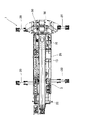
このカウンタウェイト着脱装置50は、図4(部分断面図)、図5(平面図、側面図、断面図)に示すように、旋回台10の後部の左右両側に取り付けられてロッド51aが下方に位置しシリンダチューブ51bが上方に位置するように配置された一対の昇降シリンダ51と、一対の昇降シリンダ51の各ロッド51aの先端部に形成された係合段部53と、カウンタウェイト30の上部に所定間隔を有して配置されて一対の昇降シリンダ51の各係合段部53と係合可能な一対の係合穴部60とを備える。
As shown in FIG. 4 (partial sectional view) and FIG. 5 (plan view, side view, sectional view), the counterweight attaching / detaching
昇降シリンダ51は、車体3に対して略垂直方向に配置され、油圧式の単動シリンダであり、ロッド側油室に繋がるバルブ(図示せず)の給排を制御してロッド51aの伸縮動が制御可能になっている。ロッド51aの先端部に形成された係合段部53は、ロッド51aの先端部からロッド51aの径方向外側に突出して環状に形成されている。つまり、係合段部53の外径はロッド51aのそれより大きい径である。係合段部53の上面は車体3に対して略平行に延びている。
The elevating
係合穴部60は、カウンタウェイト30の底部に設けられたウェイト分割体31に設けられた支持部材32の上端部に取り付けられている。なお、ウェイト分割体31は平板状のウェイト本体33と、このウェイト本体33の両端部に取り付けられて上方へ延びる前述した一対の支持部材32とを有してなり、ウェイト本体33の後側には左右一対の位置決め孔34が設けられている。係合穴部60は、カウンタウェイト30を車体後部に位置決めして載置した状態で車体3の前後方向に対向配置された一対の案内板61と、各案内板61の上部に設けられて対向する他の案内板61側へ突出する係止突起部63とを有してなる。
The
一対の案内板61間には、旋回台10の旋回によって移動する係合段部53が係合穴部60に対して左右両側から通過可能に開放された空間部62が形成されている。つまり、空間部62は係合段部53の移動軌跡を含む大きさを有している。この空間部62は左右両側と上部が開放されて係合段部53の通過を可能にしている。
A
また、一対の係止突出部63間には、空間部62の上部を開口して、旋回台10の旋回によって移動する昇降シリンダ51のロッド51aが係合穴部60に対して左右両側から通過可能であって、係合段部53と係止突出部63が係合可能に開放された開口部64が形成されている。つまり、開口部64はロッド51aの移動軌跡より大きく且つ係合段部53のそれより小さい大きさを有している。この開口部64は左右両側と上部が開放されてロッド51aの通過を可能にしている。係止突起部63の先端部は、直線状に形成されているが、ロッド51aの通過が可能であれば直線状に限るものではなく、湾曲状に形成されてもよい。一対の係止突起部63の高さは略同一である。
Further, between the pair of locking
支持部材32の他の支持部材32に対向する側の外周面には、上下方向に延びてウェイト本体33に接続された固定板35が取り付けられている。この固定板35の上部には係止凹部36が設けられている。
A fixing
また、旋回台10の後部には、カウンタウェイト着脱装置50によって引き上げられたカウンタウェイト30を旋回台後部に固定するための固定装置70が取り付けられている。この固定装置70は、旋回台10の後部両側面に取り付けられた回動シリンダ71と、回動シリンダ71よりも下方の旋回台10の後部に上下方向に回動自在に取り付けられた固定用アーム72と、固定用アーム72の下端部に回動自在に取り付けられて係止凹部36に係合可能なローラ部73とを有してなる。回動シリンダ71の先端部は、リンク部材75を介して固定用アーム72の上端部に接続されて、回動シリンダ71の伸縮を固定用アーム72の上下揺動に変えるようになっている。この回動シリンダ71の伸縮制御によって、固定用アーム72は略垂直方向に下方へ延びる固定位置と、旋回台10の底面に沿って延びる格納位置との間を移動可能である。回動シリンダ71の伸縮は、前述した操作キャビン25内に設けられた操作スイッチの操作によって遠隔操作可能になっている。
Further, a fixing
このように構成されたカウンタウェイト着脱装置50によって吊り上げられるカウンタウェイト30は、図6(斜視図)に示すように、中央部にウェイト分割体31上に複数のウェイト本体33を積層し、これらの両側に他のウェイト分割体38を掛止するようにして構成されている。カウンタウェイト30の上部には、カウンタウェイト30が車体後部に載置された状態で、昇降シリンダ51の前述した係合段部53が移動可能な案内溝部39が形成されている。
As shown in FIG. 6 (perspective view), the
また、カウンタウェイト着脱装置50を取り付ける旋回台10の前部には、図7(平面図)に示すように、左前側に延びる位置決め部材11が取り付けられている。この位置決め部材11の先端部には、ロックピン13を挿通する図示しない孔部が形成され、この孔部と車体3に設けられた図示しないロック孔にロックピン13を挿通すると、前述した係合段部53と係合穴部60が係合可能な位置に旋回台10の旋回位置を位置決めすることができるようになっている。
Further, as shown in FIG. 7 (plan view), a positioning member 11 extending to the left front side is attached to the front portion of the
次に、このように構成されたカウンタウェイト着脱装置50によってカウンタウェイト30を旋回台10の後部に装着する装着方法について説明する。先ず、図8(背面図)に示すように、カウンタウェイト30を車体3の後部の所定位置に載置する。このとき、車体後部に設けられた図示しない位置決めピンが前述したウェイト分割体31の位置決め孔34に挿通してカウンタウェイト30が車体後部の所定位置に位置決めされる。
Next, a mounting method for mounting the
そして、一対の昇降シリンダ51の各ロッド51aを下方へ伸長し、旋回台10を左右いずれの方向に旋回させる。つまり、旋回台10の旋回方向は、作業現場の状況に応じて決定される。このように、旋回台10の旋回方向は左右いずれでもよいので、旋回台10の旋回方向が制限されることはなく、狭い作業現場でも所望の方向に旋回台10を旋回させることができるので、カウンタウェイト30の装着の作業性を向上することができる。
And each
そして、図4に示すように、一対の昇降シリンダ51の各ロッド51aの先端部に形成された係合段部53がカウンタウェイト30の上部に配置された対応する係合穴部60と係合することができるように、旋回台10を旋回して、係合穴部60の空間部62内に係合段部53を移動させる。このとき、係合段部53は係合穴部60の空間部62を通過可能であるので、一方の係合段部53と対応する係合穴部60が、この係合段部53と対応しない他の係合穴部60よりも旋回方向下流側に位置しても、一方の係合段部53は、他の係合穴部60を通過して対応する係合穴部60に移動することができる。このため、昇降シリンダ51のロッド51aを伸長させた状態において、旋回台10の旋回角度が限られることはない。従って、旋回台10のいずれの旋回位置で昇降シリンダ51のロッド51aを伸長させて旋回台10を旋回させることができ、装着作業の作業性を向上することができる。また、ロッド51aが係合穴部60に衝突する虞はなく、昇降シリンダ51や係合穴部60の損傷を防止することができる。
And as shown in FIG. 4, the
そして、係合段部53が係合穴部60と係合可能な位置に移動すると、旋回台10の旋回を止める。このとき、係合段部53と係合穴部60の係止突起部63との係合部分は平面的に対向して移動方向に所定の幅を有するので、旋回台10の停止位置が多少ずれても係合段部53と係合穴部60との係合は可能である。このため、旋回台10の旋回停止位置を厳密にする必要はなく、停止作業を容易にすることができる。
And if the
そして、図4及び図7に示すように、旋回台10の旋回をロックするため、旋回台10に取り付けられた支持部材11を介してロックピン13を車体3に設けられたロック孔に挿入する。この旋回台10の旋回ロック作業によって、旋回台10は、係合段部53と係合穴部60を係合可能位置に位置させた状態で、旋回台10の旋回位置を位置決めすることができる。この旋回ロック作業は、カウンタウェイト30から前側に離れた旋回台10の前部において行われるので、カウンタウェイト30を気にせずに作業をすることができる。
Then, as shown in FIGS. 4 and 7, in order to lock the turning of the
そして、一対の昇降シリンダ51を縮小させて係合段部53と係合穴部60を係合し、さらに昇降シリンダ51を縮小してカウンタウェイト30を旋回台10の後部の装着位置まで引き上げる。そして、固定装置70の固定シリンダ71を縮小して、固定用アーム72を下方へ揺動させて固定位置に移動させる。固定用アーム72が固定位置に移動すると、ローラ部73が係止凹部36に係合してカウンタウェイト30が旋回台10の後部に固定される。このように旋回台後部の装着位置にカウンタウェイト30が引き上げられると、固定装置70がカウンタウェイト30を旋回台10に固定するので、カウンタウェイト30の固定作業を作業者が直接に行う必要はなく、作業者の労力負担を軽減することができる。
Then, the pair of elevating
なお、前述した実施例では、オールテレーンクレーンを例にして説明したが、ラフテレーンクレーンでも同様に本発明のカウンタウェイト着脱装置を装備することができる。また車体3を走行可能にする手段として車輪5を示したが、クローラでもよい。
In the above-described embodiment, the all terrain crane has been described as an example. However, the rough terrain crane can be similarly equipped with the counterweight attaching / detaching device of the present invention. Moreover, although the wheel 5 is shown as a means for enabling the
1 ホイールクレーン(移動式クレーン)
3 車体
5 車輪(走行手段)
10 旋回台
15 ブーム
30 カウンタウェイト
50 カウンタウェイト着脱装置
51 昇降シリンダ
51a ロッド
51b シリンダチューブ
53 係合段部
60 係合穴部
61 案内板
62 空間部
63 係止突起部
64 開口部
70 固定装置
1 Wheel crane (mobile crane)
3 Car body 5 Wheel (traveling means)
DESCRIPTION OF
Claims (6)
前記旋回台の後部の左右両側にロッドが下方に位置しシリンダチューブが上方に位置するように配設された一対の昇降シリンダと、
前記一対の昇降シリンダの各ロッドの先端部に設けられた係合段部と、
前記カウンタウェイトの上部に所定間隔を有して配置され、前記一対の昇降シリンダの各係合段部と係合可能な一対の係合穴部とを備え、
前記カウンタウェイトが前記車体の後部に載置された状態で、前記旋回台の旋回によって、前記係合段部を前記係合穴部に対して左右両側から通過移動可能にしたことを特徴とする移動式クレーンのカウンタウェイト着脱装置。 A vehicle body having a traveling means and capable of self-propelling, a swivel arranged to turn left and right with respect to the car body, a boom attached to the swivel so as to be raised and lowered, and a rear part of the swivel A counterweight attaching / detaching device for a mobile crane equipped with a counterweight detachably attached,
A pair of elevating cylinders arranged such that the rod is located below and the cylinder tube is located above both the left and right sides of the rear part of the swivel;
An engaging step provided at the tip of each rod of the pair of lifting cylinders;
A pair of engagement hole portions that are arranged at a predetermined interval on the upper part of the counterweight and are engageable with the engagement step portions of the pair of lifting cylinders;
With the counterweight placed on the rear portion of the vehicle body, the engagement step portion can be moved from both the left and right sides with respect to the engagement hole portion by turning the swivel base. Counterweight attachment / detachment device for mobile cranes.
前記一対の昇降シリンダは、前記旋回台の旋回中心から同一の所定距離を有した位置に配置され、
前記一対の係合穴部は、前記カウンタウェイトを車体後部に載置した状態で前記旋回台の旋回中心から同一の前記所定距離を有した位置に配置され、
前記係合穴部は、前記カウンタウェイトを車体後部に載置した状態で前記車体の前後方向に対向配置された一対の案内板と、各案内板の上部に設けられて対向する他の案内板側へ突出する係止突起部とを有し、前記一対の案内板間には前記旋回台の旋回によって移動する前記係合段部が通過可能に開放された空間部が形成され、前記一対の係止突出部間には前記空間部の上部を開口して前記旋回台の旋回によって移動する前記昇降シリンダの前記ロッドが通過可能に開放された開口部が形成されていることを特徴とする請求項1に記載の移動式クレーンのカウンタウェイト着脱装置。 The engaging step portion is formed in an annular shape so as to protrude radially outward of the rod from the tip portion of the rod,
The pair of lifting cylinders are disposed at positions having the same predetermined distance from the turning center of the swivel base,
The pair of engagement hole portions are disposed at positions having the same predetermined distance from the turning center of the swivel base in a state where the counterweight is placed on the rear portion of the vehicle body.
The engaging hole portion includes a pair of guide plates disposed opposite to each other in the front-rear direction of the vehicle body in a state where the counterweight is placed on the rear portion of the vehicle body, and another guide plate provided at an upper portion of each guide plate and facing each other. A locking projection that protrudes to the side, and a space portion is formed between the pair of guide plates that is open so that the engagement stepped portion that moves by turning of the swivel can pass therethrough. An opening is formed between the locking protrusions so that the upper portion of the space is opened and the rod of the elevating cylinder that moves by turning of the swivel base is opened so as to pass therethrough. Item 2. A counterweight attaching / detaching device for a mobile crane according to Item 1.
前記カウンタウェイトを前記車体の後部の所定位置に載置し、
前記旋回台の後部に設けられた一対の昇降シリンダの各ロッドを下方へ伸長して前記旋回台を左右いずれの方向に旋回させ、
前記一対の昇降シリンダの各ロッドの先端部に設けられた係合段部を、前記カウンタウェイトの上部に配置された一対の係合穴部の対応する前記係合穴部に係合可能な位置に移動させ、
前記旋回台の旋回をロックピンによってロックし、
前記一対の昇降シリンダを縮小して前記係合段部と前記係合穴部を係合して前記カウンタウェイトを前記旋回台の後部の装着位置まで引き上げることを特徴とする移動式クレーンのカウンタウェイト装着方法。 A mobile crane counter provided with a traveling means having a swivel base on a self-propelled vehicle body, a boom mounted on the swivel base, and a counterweight detachably attached to the rear part of the swivel base. A weight mounting method,
Place the counterweight at a predetermined position on the rear part of the vehicle body,
Extending each rod of a pair of lifting cylinders provided at the rear of the swivel downward to turn the swivel in either the left or right direction,
Positions at which the engagement step portions provided at the tip portions of the rods of the pair of lift cylinders can be engaged with the corresponding engagement hole portions of the pair of engagement hole portions arranged on the upper portion of the counterweight. Move to
Locking the swivel with the lock pin,
A counterweight for a mobile crane, wherein the pair of elevating cylinders are reduced to engage the engagement step portion and the engagement hole portion to raise the counterweight to a mounting position at the rear portion of the swivel base. Wearing method.
Priority Applications (1)
| Application Number | Priority Date | Filing Date | Title |
|---|---|---|---|
| JP2006225246A JP2008050068A (en) | 2006-08-22 | 2006-08-22 | Counterweight attachment/detachment device and fitting method for mobile crane |
Applications Claiming Priority (1)
| Application Number | Priority Date | Filing Date | Title |
|---|---|---|---|
| JP2006225246A JP2008050068A (en) | 2006-08-22 | 2006-08-22 | Counterweight attachment/detachment device and fitting method for mobile crane |
Publications (2)
| Publication Number | Publication Date |
|---|---|
| JP2008050068A true JP2008050068A (en) | 2008-03-06 |
| JP2008050068A5 JP2008050068A5 (en) | 2009-09-10 |
Family
ID=39234476
Family Applications (1)
| Application Number | Title | Priority Date | Filing Date |
|---|---|---|---|
| JP2006225246A Pending JP2008050068A (en) | 2006-08-22 | 2006-08-22 | Counterweight attachment/detachment device and fitting method for mobile crane |
Country Status (1)
| Country | Link |
|---|---|
| JP (1) | JP2008050068A (en) |
Cited By (5)
| Publication number | Priority date | Publication date | Assignee | Title |
|---|---|---|---|---|
| CN101624165B (en) * | 2008-07-07 | 2011-06-29 | 徐州重型机械有限公司 | Combined counterweight device and crane using same |
| CN102358578A (en) * | 2011-08-31 | 2012-02-22 | 三一汽车起重机械有限公司 | Crane and counterweight self-assembly device thereof |
| CN102583176A (en) * | 2012-03-09 | 2012-07-18 | 三一汽车起重机械有限公司 | Mobile counterweight mechanism for engineering machine |
| CN102627230A (en) * | 2012-04-11 | 2012-08-08 | 徐州重型机械有限公司 | Crane and balancing weight device thereof |
| CN103407914A (en) * | 2013-08-27 | 2013-11-27 | 徐州重型机械有限公司 | Balance weight hooking device and crane |
Citations (4)
| Publication number | Priority date | Publication date | Assignee | Title |
|---|---|---|---|---|
| JPH02132094U (en) * | 1989-04-07 | 1990-11-02 | ||
| JPH0422112U (en) * | 1990-06-07 | 1992-02-24 | ||
| JPH07223797A (en) * | 1994-02-08 | 1995-08-22 | Tadano Ltd | Attaching/detaching device for counter weight of moving crane |
| JP2002194774A (en) * | 2000-12-25 | 2002-07-10 | Kobelco Contstruction Machinery Ltd | Method and device for detaching/attaching counter weight of construction machinery |
-
2006
- 2006-08-22 JP JP2006225246A patent/JP2008050068A/en active Pending
Patent Citations (4)
| Publication number | Priority date | Publication date | Assignee | Title |
|---|---|---|---|---|
| JPH02132094U (en) * | 1989-04-07 | 1990-11-02 | ||
| JPH0422112U (en) * | 1990-06-07 | 1992-02-24 | ||
| JPH07223797A (en) * | 1994-02-08 | 1995-08-22 | Tadano Ltd | Attaching/detaching device for counter weight of moving crane |
| JP2002194774A (en) * | 2000-12-25 | 2002-07-10 | Kobelco Contstruction Machinery Ltd | Method and device for detaching/attaching counter weight of construction machinery |
Cited By (5)
| Publication number | Priority date | Publication date | Assignee | Title |
|---|---|---|---|---|
| CN101624165B (en) * | 2008-07-07 | 2011-06-29 | 徐州重型机械有限公司 | Combined counterweight device and crane using same |
| CN102358578A (en) * | 2011-08-31 | 2012-02-22 | 三一汽车起重机械有限公司 | Crane and counterweight self-assembly device thereof |
| CN102583176A (en) * | 2012-03-09 | 2012-07-18 | 三一汽车起重机械有限公司 | Mobile counterweight mechanism for engineering machine |
| CN102627230A (en) * | 2012-04-11 | 2012-08-08 | 徐州重型机械有限公司 | Crane and balancing weight device thereof |
| CN103407914A (en) * | 2013-08-27 | 2013-11-27 | 徐州重型机械有限公司 | Balance weight hooking device and crane |
Similar Documents
| Publication | Publication Date | Title |
|---|---|---|
| US9777459B2 (en) | Attachment for a skid steer loader and method of use thereof | |
| JP5513820B2 (en) | Trunnion transport system and crane using the same | |
| JP4914833B2 (en) | Crane boom telescopic device | |
| CN103711437A (en) | Hoisting derrick specially for coiled tubing equipment | |
| JP5586573B2 (en) | Crane boom telescopic device | |
| JP2008050068A (en) | Counterweight attachment/detachment device and fitting method for mobile crane | |
| US10611616B2 (en) | Aerial device with quick-coupling implement | |
| JP5328338B2 (en) | Telescopic track frame | |
| JP5442574B2 (en) | Work machine | |
| JP2010076940A (en) | Vehicle body connection system and crane using the same | |
| KR101552554B1 (en) | Counterweight for heavy-duty lift device | |
| US20170089035A1 (en) | Machine having removable tool system | |
| JP4683971B2 (en) | Jib connection structure of mobile crane | |
| JP2008050068A5 (en) | ||
| JP2015030563A (en) | Outrigger connection mechanism | |
| JP6559605B2 (en) | Auxiliary lifting device and work machine with auxiliary lifting device | |
| CN111677027B (en) | Low-top-height excavator and assembling construction method thereof | |
| JP2002194774A (en) | Method and device for detaching/attaching counter weight of construction machinery | |
| US6675719B1 (en) | Railroad car wheel handler and method | |
| JP2006028880A (en) | Pile hole excavator | |
| JP6830513B2 (en) | Auxiliary lifting device and hydraulic cylinder | |
| EP3176124B1 (en) | Crane | |
| JP6250382B2 (en) | Boom desorption structure | |
| JP6342775B2 (en) | Work vehicle | |
| JP5991291B2 (en) | Mobile crane |
Legal Events
| Date | Code | Title | Description |
|---|---|---|---|
| A521 | Written amendment |
Free format text: JAPANESE INTERMEDIATE CODE: A523 Effective date: 20090723 |
|
| A621 | Written request for application examination |
Free format text: JAPANESE INTERMEDIATE CODE: A621 Effective date: 20090723 |
|
| A977 | Report on retrieval |
Free format text: JAPANESE INTERMEDIATE CODE: A971007 Effective date: 20111222 |
|
| A131 | Notification of reasons for refusal |
Free format text: JAPANESE INTERMEDIATE CODE: A131 Effective date: 20120117 |
|
| A02 | Decision of refusal |
Free format text: JAPANESE INTERMEDIATE CODE: A02 Effective date: 20120529 |