JP2008035308A - Electronic camera and lens unit - Google Patents
Electronic camera and lens unit Download PDFInfo
- Publication number
- JP2008035308A JP2008035308A JP2006207496A JP2006207496A JP2008035308A JP 2008035308 A JP2008035308 A JP 2008035308A JP 2006207496 A JP2006207496 A JP 2006207496A JP 2006207496 A JP2006207496 A JP 2006207496A JP 2008035308 A JP2008035308 A JP 2008035308A
- Authority
- JP
- Japan
- Prior art keywords
- imaging
- driving
- angle
- tilt
- unit
- Prior art date
- Legal status (The legal status is an assumption and is not a legal conclusion. Google has not performed a legal analysis and makes no representation as to the accuracy of the status listed.)
- Pending
Links
Images


Classifications
-
- G—PHYSICS
- G03—PHOTOGRAPHY; CINEMATOGRAPHY; ANALOGOUS TECHNIQUES USING WAVES OTHER THAN OPTICAL WAVES; ELECTROGRAPHY; HOLOGRAPHY
- G03B—APPARATUS OR ARRANGEMENTS FOR TAKING PHOTOGRAPHS OR FOR PROJECTING OR VIEWING THEM; APPARATUS OR ARRANGEMENTS EMPLOYING ANALOGOUS TECHNIQUES USING WAVES OTHER THAN OPTICAL WAVES; ACCESSORIES THEREFOR
- G03B17/00—Details of cameras or camera bodies; Accessories therefor
- G03B17/02—Bodies
- G03B17/17—Bodies with reflectors arranged in beam forming the photographic image, e.g. for reducing dimensions of camera
-
- G—PHYSICS
- G03—PHOTOGRAPHY; CINEMATOGRAPHY; ANALOGOUS TECHNIQUES USING WAVES OTHER THAN OPTICAL WAVES; ELECTROGRAPHY; HOLOGRAPHY
- G03B—APPARATUS OR ARRANGEMENTS FOR TAKING PHOTOGRAPHS OR FOR PROJECTING OR VIEWING THEM; APPARATUS OR ARRANGEMENTS EMPLOYING ANALOGOUS TECHNIQUES USING WAVES OTHER THAN OPTICAL WAVES; ACCESSORIES THEREFOR
- G03B2205/00—Adjustment of optical system relative to image or object surface other than for focusing
- G03B2205/0007—Movement of one or more optical elements for control of motion blur
- G03B2205/0023—Movement of one or more optical elements for control of motion blur by tilting or inclining one or more optical elements with respect to the optical axis
Abstract
Description
本発明は、被写体を撮像して静止画で記録する電子カメラ及びこの電子カメラに用いられるレンズユニットに関する。 The present invention relates to an electronic camera that captures an image of a subject and records it as a still image, and a lens unit used in the electronic camera.
従来、手ブレ補正機能を具備する電子カメラや、あおり撮影機能を具備する電子カメラが提案されてるに至っている。手ブレ補正機能を具備する電子カメラにおいては、検出した手ブレ量に応じて、CCD等の撮像素子を光軸と垂直方向に上下左右に駆動することにより、ブレのある画像の撮影を防止する(特許文献1参照)。 Conventionally, an electronic camera having a camera shake correction function and an electronic camera having a tilt shooting function have been proposed. In an electronic camera having a camera shake correction function, an image pickup device such as a CCD is driven vertically and horizontally in the direction perpendicular to the optical axis in accordance with the detected amount of camera shake, thereby preventing shooting of a blurred image. (See Patent Document 1).
また、あおり撮影機能を具備する電子カメラにおいては、撮像レンズを内蔵する鏡筒本体と、撮像素子及びこの撮像素子をシフトさせるシフト機構を内蔵する撮像素子ブロックとが一体に固着されている。そして、この撮像素子ブロックが一体に固着された鏡筒本体を回動部材により回動させることにより、あおり撮影を可能にする(特許文献2参照)。このあおり撮影により、例えばビルなどを見上げる撮影でも、中央だけでなく(距離の違う)ビルの上下端にもピントを合わせた撮影ができたり、広角では通常湾曲して撮影されてしまうビルの縁などを図面のように直線に撮影する等が可能となる。
しかしながら、前者の電子カメラにあっては、手ブレ補正機能は具備するもの、あおり撮影機能を具備するものではなく、後者の電子カメラにあっては、あおり撮影機能は具備するもの、手ブレ補正機能を具備するものではない。しかも、後者にあっては、撮像素子をシフトさせるシフト機構を内蔵する撮像素子ブロックが一体に固着された鏡筒本体を回動させる構成であることから、駆動(回動)する対象が大きく、コンパクトサイズの電子カメラに採用することは困難である。 However, the former electronic camera has a camera shake correction function and does not have a tilt shooting function. The latter electronic camera has a tilt shooting function and has a camera shake correction function. It does not have a function. In addition, in the latter, since the imaging element block incorporating the shift mechanism for shifting the imaging element is configured to rotate the lens barrel body fixed integrally, the object to be driven (rotated) is large. It is difficult to adopt for a compact electronic camera.
本発明は、かかる従来の課題に鑑みてなされたものであり、簡単な構造でありながら、手ブレ補正機能とあおり撮影機能とを併有する電子カメラ及びレンズユニットを提供することを目的とする。 The present invention has been made in view of such conventional problems, and an object thereof is to provide an electronic camera and a lens unit that have both a camera shake correction function and a tilt shooting function while having a simple structure.
前記課題を解決するために請求項1記載の発明に係る電子カメラは、光学系により結像される被写体像を撮像する撮像面を有する撮像手段と、この撮像手段を駆動して前記撮像面に沿った方向に変位させる駆動手段と、カメラ本体のブレを検出するブレ検出手段と、 In order to solve the above-described problem, an electronic camera according to a first aspect of the present invention includes an imaging unit having an imaging surface for imaging a subject image formed by an optical system, and driving the imaging unit to the imaging surface. Driving means for displacing in the direction along, blur detection means for detecting blur of the camera body,
このブレ検出手段により検出される前記カメラ本体のブレに基づき、前記駆動手段を制御し前記撮像手段を変位させるブレ補正制御手段と、設定モードに応じて前記駆動手段を制御し、前記撮像手段を変位させるとともに当該変位させた位置に定位させる撮影制御手段とを備える。 Based on the blur of the camera body detected by the blur detection means, the blur correction control means for controlling the driving means to displace the imaging means, the driving means according to a setting mode, and the imaging means Photographing control means for displacing and localizing to the displaced position.
また、請求項2記載の発明に係る電子カメラは、外部からの光を光学系に反射させる反射手段と、この反射手段を駆動して反射角度を変化させる第1の駆動手段と、前記光学系により結像される被写体像を撮像する撮像面を有する撮像手段と、この撮像手段を駆動して前記撮像面を角度変化させる第2の駆動手段と、カメラ本体のブレを検出するブレ検出手段と、このブレ検出手段により検出される前記カメラ本体のブレに基づき、前記第1の駆動手段を制御し前記反射手段を角度変化させるブレ補正制御手段と、設定モードに応じて前記第2の駆動手段を制御し、前記撮像手段を角度変化させるとともに当該角度変化させた位置に定位させる撮影制御手段とを備える。 According to a second aspect of the present invention, there is provided an electronic camera comprising: a reflecting means for reflecting light from the outside to the optical system; a first driving means for driving the reflecting means to change a reflection angle; and the optical system. Imaging means having an imaging surface for imaging the subject image formed by the image forming apparatus, second driving means for driving the imaging means to change the angle of the imaging surface, and blur detection means for detecting camera shake. And a blur correction control means for controlling the first drive means to change the angle of the reflection means based on the shake of the camera body detected by the shake detection means, and the second drive means according to a setting mode. And an imaging control unit that changes the angle of the imaging unit and localizes the imaging unit to the position where the angle is changed.
また、請求項記3載の発明に係る電子カメラは、前記撮影制御手段は、前記ブレ補正制御手段による撮像手段の動作範囲よりも広い動作範囲において、前記撮像手段を変位又は角度変化させる。 In the electronic camera according to the third aspect of the invention, the photographing control unit displaces or changes the angle of the imaging unit in an operation range wider than the operation range of the imaging unit by the blur correction control unit.
また、請求項4記載の発明に係る電子カメラは、第1及び第2のモードを選択的に設定するモード設定手段と、このモード設定手段により第1のモードが設定されている状態においては、前記ブレ補正制御手段を動作させ、前記第2のモードが設定されている状態においては、前記撮影制御手段を動作させる動作制御手段を更に備える。 According to a fourth aspect of the present invention, in the electronic camera according to the invention, the mode setting means for selectively setting the first and second modes, and the state in which the first mode is set by the mode setting means, In the state where the blur correction control means is operated and the second mode is set, operation control means for operating the photographing control means is further provided.
また、請求項5記載の発明に係る電子カメラは、前記モード設定手段は、更に第3のモードを選択的に設定し、前記動作制御手段は、前記第3のモードが設定されている状態においては、前記撮影制御手段を動作させた状態で前記ブレ補正制御手段を動作させる。 In the electronic camera according to the fifth aspect of the present invention, the mode setting means further selectively sets the third mode, and the operation control means is in a state where the third mode is set. Operates the blur correction control means in a state where the photographing control means is operated.
また、請求項6記載の発明に係る電子カメラは、前記撮影制御手段を動作させた状態で前記ブレ補正制御手段を動作させる。 An electronic camera according to a sixth aspect of the invention operates the blur correction control unit in a state where the photographing control unit is operated.
また、請求項7記載の発明に係る電子カメラは、前記撮影制御手段は、操作に応じた位置に前記撮像手段を変位させる手動変位手段と、所定の演算を実行し算出された位置に前記撮像手段を変位させる自動変位手段とを含む。 According to a seventh aspect of the present invention, in the electronic camera according to the seventh aspect of the invention, the photographing control means performs manual calculation means for displacing the image pickup means to a position corresponding to an operation, and performs a predetermined calculation to obtain the image pickup position. Automatic displacement means for displacing the means.
また、請求項8記載の発明に係る電子カメラは、前記駆動手段は、前記撮像手段を前記撮像面に沿った上下方向に変位させる上下駆動手段と、前記撮像面に沿った左右方向に変位させる左右駆動手段とを備える。 According to an eighth aspect of the present invention, in the electronic camera according to the eighth aspect, the driving unit displaces the imaging unit in a vertical direction along the imaging surface and a horizontal driving unit along the imaging surface. Left and right drive means.
また、請求項9記載の発明に係る電子カメラは、前記撮影制御手段は、操作に応じた角度に前記撮像手段を変化させる手動変角手段と、所定の演算を実行し算出された角度に前記撮像手段を変化させる自動変角手段とを含む。 Further, in the electronic camera according to a ninth aspect of the present invention, the photographing control means includes a manual angle changing means for changing the imaging means to an angle corresponding to an operation, and a predetermined calculation to execute the predetermined calculation. Automatic angle changing means for changing the imaging means.
また、請求項10記載の発明に係る電子カメラは、前記第1及び第2の駆動手段は、前記反射手段又は撮像手段を水平軸を中心にして上下方向に角度変化させる上下駆動手段と、垂直軸を中心にして左右方向に角度変化させる左右駆動手段ととを備える。 According to a tenth aspect of the present invention, in the electronic camera according to the tenth aspect, the first and second driving means include a vertical driving means for changing the angle of the reflecting means or the imaging means in the vertical direction around a horizontal axis, and a vertical driving means. Left-right drive means for changing the angle in the left-right direction about the axis.
また、請求項11記載の発明に係るレンズユニットは、光学系と、外部からの光を前記光学系に反射させる反射手段と、この反射手段を駆動して反射角度を変化させる第1の駆動手段と、前記光学系により結像される被写体像を撮像する撮像面を有する撮像手段と、この撮像手段を駆動して前記撮像面を角度変化させる第2の駆動手段とを備える。 According to an eleventh aspect of the present invention, there is provided a lens unit comprising: an optical system; reflecting means for reflecting light from outside to the optical system; and first driving means for driving the reflecting means to change a reflection angle. And imaging means having an imaging surface for imaging a subject image formed by the optical system, and second driving means for driving the imaging means to change the angle of the imaging surface.
以上説明したように請求項1に係る電子カメラによれば、光学系により結像される被写体像を撮像する撮像面を有する撮像手段を、カメラ本体のブレに基づき変位させ、また、設定モードに応じて変位させるとともに当該変位させた位置に定位させるようにしたことから、撮像手段を駆動する簡単な構造でありながら、手ブレ補正機能とあおり撮影機能とを併有することができる。 As described above, according to the electronic camera of the first aspect, the image pickup means having the image pickup surface for picking up the subject image formed by the optical system is displaced based on the shake of the camera body, and the setting mode is set. Accordingly, the camera shake correction function and the tilt shooting function can be provided together with a simple structure for driving the image pickup means.
また、請求項2に係る電子カメラ及び請求項10に係るレンズユニットによれば、外部からの光を光学系に反射させる反射手段をカメラ本体のブレに基づき角度変化させ、また、光学系により結像される被写体像を撮像する撮像面を有する撮像手段とを角度変化させるようにしたことから、共に光学系と関係して配置される反射手段と撮像手段とを駆動する簡単な構造でありながら、手ブレ補正機能とあおり撮影機能とを併有することができる。
Further, according to the electronic camera according to
以下、本発明の一実施の形態を図に従って説明する。
(第1の実施の形態)
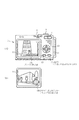
図1(A)は各実施の形態に共通するデジタルカメラ1の正面図、(B)は側面透視図、図2(A)は背面図、(B)は表示画面例を示す図である。このデジタルカメラ1の本体2には、その上面部に半押し機能を備えたレリーズ釦(シャッタースイッチ)3と電源スイッチ4とが配置されており、正面部にはグリップ部5、ストロボ6及び撮像レンズ部の受光窓7が配置されている。また、背面部には、モード切替スイッチ8、ズーム操作キー9、カーソルキー10、決定/OKキー11、手振れ量表示のオン・オフキーとして兼用されるDISPキー12、メニューキー13及び電子ファインダとしても機能するLCDからなる表示部14が配置されている。この表示部14には、モードに応じてブレ量の表示部14aと、あおり撮又はティルト(上下方向の回動)/スィング(左右方向の回動)量の表示部14bとが選択的に表示される。また、内部には垂直方向の角速度を検出する第1角速度センサ16と水平方向の角加速度を検出する第2角速度センサ17が配置されているとともに、回動式ミラー18、レンズ群19及び撮像素子20等が配置され、撮像素子20は撮像素子駆動機構21に固定されている。
Hereinafter, an embodiment of the present invention will be described with reference to the drawings.
(First embodiment)
FIG. 1A is a front view of a digital camera 1 common to each embodiment, FIG. 1B is a side perspective view, FIG. 2A is a rear view, and FIG. The
図3は、前記撮像素子駆動機構21の詳細を示す斜視図である。この撮像素子駆動機構21は、平面視において略コ字状の固定台22を有しており、固定台22の前面には開口部22aが設けられている。この固定台22の上端部間にはX方向ガイドレール23が架装され、下端部間にはX方向駆動スクリュー24が回転自在に架装されている。X方向駆動スクリュー24の一端部には、減速歯車25が固定され、この減速歯車25はステップモータであるX方向駆動用モータ26の回転軸に固定された駆動歯車27に噛合されている。
FIG. 3 is a perspective view showing details of the image
前記X方向ガイドレール23には、側面視において略コ字状であって前面に開口部28aを有するX方向スライダ28の上端部が摺動自在に外嵌されており、前記X方向駆動スクリュー24にはX方向スライダ28の下端部が螺合されている。また、X方向スライダ28の上下端部間には、上下方向に延在する平行なY方向ガイドレール29とY方向駆動スクリュー30とが配置されている。Y方向駆動スクリュー30は回転自在であって、下端部には減速歯車31が固定され、この減速歯車31はステップモータであるY方向駆動用モータ32の回転軸に固定された駆動歯車33に噛合されている。また、前記Y方向ガイドレール29は、Y方向スライダ34の一端部が摺動自在に外嵌されており、前記Y方向駆動スクリュー30にはY方向スライダ34の他端部が螺合されている。
An upper end portion of an
そして、このY方向スライダ34の前面に前記撮像素子20が固着されており、よって、撮像素子20の撮像面は、前記両開口部22a、28aを介して外部に露出している。また、X方向駆動用モータ26が正転又は逆転することにより、X方向スライダ28がX方向に駆動されて撮像素子20がX方向に移動し、Y方向駆動用モータ32が正転又は逆転することにより、Y方向スライダ34がY方向に駆動されて撮像素子20がY方向に移動するように構成されている。
The
図4は、デジタルカメラ1の回路構成を示すブロック図である。図において、操作入力部40は、前記レリーズ釦3や電源スイッチ4等の図1に示したスイッチやキー群等で構成され、このスイッチ及びキー群の操作情報は、入力回路41を介して、主制御部42に入力される。主制御部42は、CPU43及びその周辺回路と、CPU43の作業用メモリであるRAM等から構成されるマイクロコンピュータであり、各部を制御する。
FIG. 4 is a block diagram showing a circuit configuration of the digital camera 1. In the figure, an
この主制御部42には、表示駆動回路44、画像バッファメモリ45、信号処理回路46、プログラムメモリ47、データメモリ48、入出力インターフェース49、電源制御ブロック50、通信制御ブロック51、撮影制御部52及びHDD・IF53が接続されている。表示駆動回路44は、前記表示部14を駆動し、画像バッファメモリ45は、画像データを処理する際等において該画像データを一時的に格納する。
The
信号処理回路46は、撮像素子20から取り込んだ画像信号に対する各種処理を実行するCDS54、アンプ55、A/D変換器56、WB補正部57、カラー補間部58、ガンマ補正部59、マトリクス60からなる。画像CODEC61は、この信号処理回路46で処理され画像バッファメモリ45に記憶された画像画像データを記録時には圧縮符号化処理し、記録した画像データを再生する際には伸長復号化処理する。プログラムメモリ47は、後述するフローチャートに示す主制御部42の制御プログラムを格納しており、データメモリ48は各種データが予め格納されているとともに画像データ以外の他のデータを格納する。入出力インターフェース49は、着脱自在な外部メモリ媒体62に接続されている。通信制御ブロック51は無線LAN等送受信部63を介してアンテナ64に接続され、電源制御ブロック50には、電池65が接続されている。電池65からの電力は電源制御ブロック50及び主制御部42を介して各部に供給される。
The
前記撮影制御部52には、前記ストロボ6を駆動するストロボ駆動回路66が接続されているとともに、測距センサ67と測光センサ68からの信号を検出して出力す検出回路69、70が接続されている。さらに前記撮影制御部52には、前記第1及び第2角速度センサ16、17が各々検出回路71、72、積分器75、76及びブレ量計測部77を介して接続されている。
A
一方、前記レンズ群19の後方には前記撮像素子駆動機構21に固定された前記撮像素子20が配置されているとともに、レンズ群19中には絞り78が介挿され、撮像素子20の前面にはシャッター79が配置されている。
On the other hand, the
さらに、前記撮影制御部52には、焦点レンズ駆動部80、変倍レンズ駆動部81、絞り駆動部82とシャッター駆動部83、撮像素子あおり駆動部84、撮像素子走査信号駆動部85が接続されている。一方、撮影制御部52には、ズーム/AF制御部86、被写体距離計測部87、露出制御部88、あおり撮影制御部89、撮像素子移動制御部91、ブレ補正制御部90、撮影モード選択部92が設けられている。ズーム/AF制御部86は、両検出回路69からの検出値に基づき被写体距離計測部87が計測した距離に応じて、焦点レンズ駆動部80、変倍レンズ駆動部81を制御する。露出制御部88は、検出回路70からの検出値と撮影モード選択部92で選択された撮影モードとに基づき、両駆動回路82、83を制御する。あおり撮影制御部89には、ズーム/AF制御部86と被写体距離計測部87及び撮影モード選択部92からの信号が入力され、撮像素子移動制御部91にはあおり撮影制御部89とブレ補正制御部90からの信号が入力される。撮像素子移動制御部91はこれら入力信号に基づき、撮像素子あおり駆動部84を制御し、撮像素子あおり駆動部84は前記撮像素子駆動機構21のX方向駆動用モータ26とY方向駆動用モータ32とを駆動する。また、撮像素子走査信号駆動部85は、撮像素子20と信号処理回路46とを駆動する。
Further, a focus lens driving unit 80, a variable magnification
他方、HDD・IF53には、HDD記憶装置93が接続されている。HDD記憶装置93は、ディスク媒体94を有するとともに、モータ95、モータドライバ96、マイコン部97、VCモータ98、ヘッドアンプ99、リード/ライトチャンネル100、HDD制御部101等を有している。
On the other hand, an
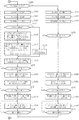
以上の構成に係る本実施の形態において、主制御部42がプログラムメモリ47に格納されているプログラムに基づき各部を制御することにより、デジタルカメラ1は図5及び図6に示す一連のフローチャートに示すように動作する。先ず、ユーザによる操作入力部40での操作に応じて、撮影モードを設定するとともに、複数のAF枠から選択されたAF枠の設定やストロボの発光条件等の撮影条件を設定する(図5;ステップS101)。また、ユーザによる操作入力部40での操作により、手ブレ補正撮影モードが設定されている否かを判断し(ステップS102)、手ブレ補正撮影モード設定されていない場合には図6のステップS120に進む。
In the present embodiment having the above configuration, the digital camera 1 is shown in a series of flowcharts shown in FIGS. 5 and 6 when the
手ブレ補正撮影モードが設定されている場合には、測光処理、WB処理を実行するとともに(ステップS103)、ズーム処理、AF処理を実行した後(ステップS104)、被写体像のスルー画像を表示部14に表示させる(ステップS105)。したがって、ユーザはこの表示部14に表示されたスルー画像を見ながら、このデジタルカメラ1の向きを調整する。
When the camera shake correction shooting mode is set, photometry processing and WB processing are executed (step S103), zoom processing and AF processing are executed (step S104), and a through image of the subject image is displayed on the display unit. 14 is displayed (step S105). Therefore, the user adjusts the direction of the digital camera 1 while viewing the through image displayed on the
この間、レリーズ釦3が半押しされたか否かを判断し(ステップS106)、レリーズ釦3が半押しされるまでステップS103からの処理を繰り返す。そして、ユーザがレリーズ釦3を半押しすると、ステップS106の判断がYESとなる。したがって、ステップS106からステップS107に進み、測光処理を行って、前記ステップS101で設定された撮影条件と、この測光処理により得られた測光値とに応じて、露出条件を設定する(ステップS107)。両角速度センサ16、17等からなるブレ検出回路により検出されている当該デジタルカメラ1の垂直方向及び水平方向のブレ量の検出を開始し(ステップS108)、前記ステップS101での撮影条件の設定により選択されているAF枠が合焦するように、AF処理を実行する(ステップS109)。次に、レリーズ釦3が全押しされたか否かを判断し(ステップS110)、レリーズ釦3が全押しされるまで待機する。
During this time, it is determined whether or not the
そして、ユーザが半押ししていたレリーズ釦3を全押しすると、ステップS110の判断がYESとなる。したがって、ステップS110からステップS111に進み、前記ステップS107で設定された露出条件が示す設定露出時間に従って、露出時間タイマーを設定し、タイマー計時を開始する(ステップS111)。また、両角速度センサ16、17により検出されている当該デジタルカメラ1の垂直方向及び水平方向のブレ量を検出する(ステップS112)。そして、この検出したブレ量に応じて、撮像素子駆動機構21により撮像素子20を上下、左右に駆動するとともに(ステップS113)、撮影条件に応じて露出(露光)及び撮影処理を実行する(ステップS114)。
When the
次に、前記露出タイマーにより計時している露出時間が終了となったか否か、つまり露出タイマーの残時間が「0」となったか否かを判断し(ステップS115)、露出時間が終了となってない場合には、ステップS112に戻って、このステップS112からの処理を繰り返し実行する。そして、露出時間が終了し露出タイマーの残存時間が「0」となった場合には、撮影画像データを圧縮、符号化し(ステップS116)、この圧縮、符号化した撮影画像をメモリ(外部メモリ媒体62又はディスク媒体94)に記録する(ステップS117)。さらに、撮影画像を表示部14にレビュー表示し(ステップS118)、撮像素子駆動機構21により撮像素子20を初期位置(中央)に戻す(ステップS119)。
Next, it is determined whether or not the exposure time counted by the exposure timer has ended, that is, whether or not the remaining time of the exposure timer has become “0” (step S115), and the exposure time ends. If not, the process returns to step S112 and the process from step S112 is repeatedly executed. When the exposure time ends and the remaining time of the exposure timer reaches “0”, the captured image data is compressed and encoded (step S116), and the compressed and encoded captured image is stored in the memory (external memory medium). 62 or the disk medium 94) (step S117). Further, the photographed image is reviewed and displayed on the display unit 14 (step S118), and the
他方、前記ステップS102での判断の結果、手ブレ補正撮影モードが設定されていなかった場合には、このステップS102から図6のフローに進み、あおり撮影モードが設定されているか否かを判断する(ステップS120)。あおり撮影モードが設定されている場合には、測光処理、WB処理を実行するとともに(ステップS121)、ズーム処理、AF処理を実行した後(ステップS122)、被写体像のスルー画像を表示部14に表示させる(ステップS123)。したがって、ユーザはこの表示部14に表示されたスルー画像を見ながら、このデジタルカメラ1の向きを調整する。
On the other hand, if the camera shake correction shooting mode is not set as a result of the determination in step S102, the process proceeds from this step S102 to the flow of FIG. 6 to determine whether the tilt shooting mode is set. (Step S120). When the tilt shooting mode is set, photometry processing and WB processing are executed (step S121), zoom processing and AF processing are executed (step S122), and a through image of the subject image is displayed on the
次に、あおり撮影モードにおける「自動あおり」が設定されているか否かを判断する(ステップS124)。設定されていない場合には、ユーザによる操作入力部40での操作に応じて、撮像素子20の移動量であるあおり量dを設定する(ステップS125)。また、「自動あおり」が設定されている場合には、ユーザの操作入力部40での操作よる被写体の高さ(h)を入力させ、撮影距離(L)を測定又は入力させ、焦点距離(f)、画角(θ)又は撮像サイズ(Y′)の情報を読み込む(ステップS126)。引き続き、被写体の高さ(h)と撮影距離(L)、焦点距離(f)等に応じて、下記例示式によりあおり量(撮像素子の移動量)dを算出して設定する(ステップS127)。
d=[(h/L)−tan(θ/2)]×f
又は、
d=[f×(h/L)−(Y′/2)]
Next, it is determined whether or not “automatic tilt” in the tilt shooting mode is set (step S124). If not set, a tilt amount d that is a moving amount of the
d = [(h / L) −tan (θ / 2)] × f
Or
d = [f × (h / L) − (Y ′ / 2)]
さらに、このステップS127又は前記ステップS125で設定されたあおり量dだけ、撮像素子駆動機構21により撮像素子20を(例えば下方に)移動する(ステップS128)。次に、レリーズ釦3が半押しされたか否かを判断し(ステップS129)、レリーズ釦3が半押しされるまでステップS121からの処理を繰り返す。そして、ユーザがレリーズ釦3を半押しすると、ステップS129の判断がYESとなる。したがって、ステップS129からステップS130に進み、測光処理を行って、前記ステップS101で設定された撮影条件と、この測光処理により得られた測光値とに応じて、露出条件を設定する(ステップS130)。また、中央及び上下(又は左右)のAF枠が共に合焦するように、AF処理を実行する(ステップS131)。つまり、あおり撮影モードが設定されている場合には、前記ステップS123で表示部14にスルー画像を表示する際に、表示部14の中央及び上下左右にAF枠を表示し、この央及び上下(又は左右)のAF枠内の画像が合焦するように、AF処理を実行する。
Further, the
引き続き、レリーズ釦3が全押しされたか否かを判断し(ステップS132)、レリーズ釦3が全押しされるまで待機する。そして、ユーザが半押ししていたレリーズ釦3を全押しすると、ステップS132の判断がYESとなる。したがって、ステップS132からステップS133に進み、前記ステップS130で設定された露出条件が示す設定露出時間に従って、露出時間タイマーを設定し、タイマー計時を開始する(ステップS133)。また、撮影条件に応じて露出(露光)及び撮影処理を実行し(ステップS134)、前記露出タイマーにより計時している露出時間が終了となったか否か、つまり露出タイマーの残時間が「0」となったか否かを判断する(ステップS135)。露出時間が終了となってない場合には、ステップS134に戻って処理を繰り返し実行する。露出時間が終了し露出タイマーの残存時間が「0」となった場合には、前述した図5のステップS116に進んでS116〜S119の処理を実行する。
Subsequently, it is determined whether or not the
また、ステップS120の判断がNOである場合、つまり手ブレ補正撮影モードもあおり撮影モードのいずれも設定されていない場合には、ステップS136に進む。そして、測光処理、WB処理を実行するとともに(ステップS136)、ズーム処理、AF処理を実行した後(ステップS137)、被写体像のスルー画像を表示部14に表示させる(ステップS138)。したがって、ユーザはこの表示部14に表示されたスルー画像を見ながら、このデジタルカメラ1の向きを調整する。
If the determination in step S120 is no, that is, if there is a camera shake correction shooting mode and no shooting mode is set, the process proceeds to step S136. Then, photometry processing and WB processing are executed (step S136), and after zoom processing and AF processing are executed (step S137), a through image of the subject image is displayed on the display unit 14 (step S138). Therefore, the user adjusts the direction of the digital camera 1 while viewing the through image displayed on the
次に、レリーズ釦3が半押しされたか否かを判断し(ステップS139)、レリーズ釦3が半押しされるまでステップS136からの処理を繰り返す。そして、ユーザがレリーズ釦3を半押しすると、ステップS139の判断がYESとなる。したがって、ステップS139からステップS140に進み、測光処理を行って、前記ステップS101で設定された撮影条件と、この測光処理により得られた測光値とに応じて、露出条件を設定する(ステップS140)。また、選択されているAF枠が合焦するように、AF処理を実行し(ステップS141)、レリーズ釦3が全押しされたか否かを判断し(ステップS142)、レリーズ釦3が全押しされるまで待機する。そして、ユーザが半押ししていたレリーズ釦3を全押しすると、ステップS142の判断がYESとなる。したがって、ステップS142からステップS143に進み、前記ステップS140で設定された露出条件が示す設定露出時間に従って、露出時間タイマーを設定し、タイマー計時を開始する(ステップS143)。また、撮影条件に応じて露出(露光)及び撮影処理を実行し(ステップS144)、前記露出タイマーにより計時している露出時間が終了となったか否か、つまり露出タイマーの残時間が「0」となったか否かを判断する(ステップS145)。露出時間が終了となってない場合には、ステップS144に戻って処理を繰り返し実行する。露出時間が終了し露出タイマーの残存時間が「0」となった場合には、前述した図5のステップS116に進んでS116〜S119の処理を実行する。
Next, it is determined whether or not the
以上の第1の実施の形態において、予め「ライズ/フォール、又はシフト」について説明すると、レンズ光輪に対して垂直方向の上下にレンズ又はフィルム位置を平行移動させると、構図や像の歪みの修正ができる。例えば、高いビルを下から見上げる角度で撮影すると、遠近感によりビルは上すぼまりで写ってしまうが、このとき、レンズ面と撮像面がビルと平行になるように配し、レンズ側をライズ(=撮像面側をフォール)させると、上すぼまりな像を補正して図面のようにまっすぐに撮影できる。また、逆にレンズ側をフォールさせると、遠近感を誇張したような撮影もできる。シフトでは、同様に、光軸に対して垂直方向の左右に、レンズ面又は撮像面を平行移動させて、構図の修正や歪みの矯正ができる。例えば、鏡の中心より左右にずれた位置から撮影しても、撮影者が映らず、鏡の中央で撮ったような写真が得られる。 In the first embodiment described above, “rise / fall or shift” will be described in advance. When the lens or film position is moved up and down in the vertical direction with respect to the lens halo, the composition and image distortion are corrected. Can do. For example, if you shoot a high building at an angle looking up from the bottom, the building will appear as a concavity due to perspective, but at this time, the lens surface and the imaging surface are parallel to the building, and the lens side is When rising (= falling on the imaging surface side), it is possible to shoot straight as shown in the drawing after correcting the narrow image. On the other hand, if the lens side is folded, it is possible to shoot with an exaggerated perspective. In the shift, similarly, the lens surface or the imaging surface can be translated to the left and right in the direction perpendicular to the optical axis to correct the composition and correct the distortion. For example, even if an image is taken from a position that is shifted to the left or right from the center of the mirror, the photographer does not appear and a photograph that is taken at the center of the mirror can be obtained.
そして、第1の実施の形態の撮影モードにおける撮影である「あおり撮影」(あおり撮影(1)という)では、フィールドカメラや蛇腹式カメラや、あるいは、あおり撮影用シフトレンズにおける「ライズ/フォール」や「シフト」などのいわゆるあおり撮影(ディスプレースメント)とは、逆に撮影レンズ側を移動させるのではなく、撮像素子20側(撮像面側)を移動させる。しかし、このようなあおり撮影においても、同等の撮影効果を得ることができる。
In “aori shooting” (referred to as “aori shooting (1)”) that is shooting in the shooting mode of the first embodiment, “rise / fall” in a field camera, a bellows type camera, or a tilt shooting shift lens. In contrast to so-called tilt shooting (displacement) such as “shift”, the
例えば、図7に示すように、通常、建物を下から見上げるような角度で撮影すると、遠近感によりビルは上すぼまりで写ってしまう。また、光輪中心近くにピント合わせると、上部や下部はピンボケになる。このとき、図8に示すように、レンズ面と撮像面が建物と平行になるようにカメラを構えて、撮像素子20側を下側に平行移動させると(レンズ側をライズさせることに相当)、図の撮影画像例(A)のように、上すぼまりに歪んだ像を補正して正面図のようにまっすぐに撮影できる。また、建物の中央だけでなく、上下端にも同時にピントを合わせた撮影が可能になる。このとき、撮像素子の移動量(あおり量)dは、例えば次式で求めることができる。
For example, as shown in FIG. 7, usually, when the building is photographed at an angle that looks up from below, the building appears to be narrowed due to perspective. Also, when focusing near the center of the halo, the upper and lower parts become out of focus. At this time, as shown in FIG. 8, if the camera is held so that the lens surface and the imaging surface are parallel to the building, and the
移動量(あおり量)d={(被写体の高さh/撮影距離L)−tan(画角θ/2)}×焦点距離f
したがって、被写体の遠近感による構図や歪みを補正して、正面図のようにまっすぐに、また、被写体前面にピントが合うようにあおり量(ライズ/フォール量、シフト量)を自動設定して、「自動あおり補正撮影」する場合には、ビルの高さなど被写体の高さ(h)、及び、撮影距離(L)を、予め入力するか、三角測量法の原理で(ミラーやプリズムとPSD受光センサ等により)距離計測したり、超音波や赤外光などによる往復距離からアクティブ式に自動距離計測して、また、撮影時のズームレンズなど撮影レンズの焦点距離(f)情報、及び、それに相当する画角(θ)情報を読み込んで、算出された所要の移動量(あおり量)dを、自動あおり設定操作により設定して、撮像素子駆動機構によりその移動量(あおり量)dに相当する駆動動作を行えばよい。
Movement amount (tilting amount) d = {(subject height h / shooting distance L) -tan (angle of view θ / 2)} × focal length f
Therefore, the composition and distortion due to the perspective of the subject are corrected, and the tilt amount (rise / fall amount, shift amount) is automatically set so that it is straight as shown in the front view and the subject is in focus. When performing “automatic tilt correction shooting”, the height (h) of the subject such as the height of the building and the shooting distance (L) are input in advance or based on the principle of triangulation (mirror, prism and PSD). Distance measurement (by a light receiving sensor or the like), automatic distance measurement automatically from a round trip distance by ultrasonic waves or infrared light, etc., and focal length (f) information of a photographing lens such as a zoom lens at the time of photographing, and The corresponding angle of view (θ) information is read, the calculated required movement amount (tilting amount) d is set by an automatic tilt setting operation, and the moving amount (tilting amount) d is set by the image sensor driving mechanism. Equivalent That may be carried out the driving operation.
また、このとき、ズームレンズ等において、撮像素子の縦(又は横)方向の撮像サイズ(Y′)と焦点距離(f)と縦(又は横)方向の撮影画角(θ)との関係から、画角θは、Y′/2f =tan(θ/2)又は、画角θ=2tan−1(Y′/2f)となるので、移動量(アオリ量)d=[(h/L)−(Y′/2f)]×f=[fx(h/L)−(Y′/2)]と計算して、tan(画角θ/2)などの三角関数計算を不要としてもよい。また、逆に、撮像素子側を上側に平行移動させると(レンズ側をフォールさせることに相当)、遠近感を誇張、強調したようなあおり撮影による作画表現をしてもよい。また、上下方向(ライズ/フォール)に平行移動するではなく、左右方向(シフト)に平行移動して撮影する場合も同様であり、また、上下、左右を組合わせて、それぞれ所望のあおり量だけ、撮像面を偏心させた位置で撮影してもよい。また、カーソルキー10などにより、手動であおり量(ライズ/フォール量、シフト量)、又は、あおり位置等を操作してあおり撮影してもよい。
At this time, in a zoom lens or the like, from the relationship between the imaging size (Y ′) in the vertical (or horizontal) direction, the focal length (f), and the shooting field angle (θ) in the vertical (or horizontal) direction of the imaging device. Since the angle of view θ is Y ′ / 2f = tan (θ / 2) or the angle of view θ = 2 tan −1 (Y ′ / 2f), the movement amount (tilt amount) d = [(h / L) -(Y '/ 2f)] * f = [fx (h / L)-(Y' / 2)] is calculated, and trigonometric functions such as tan (angle of view θ / 2) may be unnecessary. Conversely, when the image sensor side is translated upward (equivalent to falling the lens side), drawing expression by tilt shooting may be used in which the perspective is exaggerated and emphasized. The same applies when shooting in parallel with the horizontal direction (shift) instead of parallel movement in the vertical direction (rise / fall). The image may be taken at a position where the imaging surface is decentered. Further, manual shooting may be performed by operating the tilt amount (rise / fall amount, shift amount), tilt position, or the like manually with the
また、図9(A)に示す手ブレのない状態から、同図(B)に示す手ブレが生じた場合には、前述したステップS112及びS113での処理により、プレ検出信号に応じて光軸上の撮像素子20を上下、左右に移動させて光軸を一定に保ち、ブレをキャンセルすることができる。したがって、従来の手ブレ補正装置やコンパクトカメラではできなかった「あおり撮影(1)」ができるようにするとともに、機器が大型になることなく、手ブレ補正装置とも兼用できるように構成することができる。
In addition, when the camera shake shown in FIG. 9B occurs from the state where there is no camera shake shown in FIG. 9A, the light in accordance with the pre-detection signal is obtained by the processing in steps S112 and S113 described above. The
(第2の実施の形態) (Second Embodiment)
図10は、本発明の第2の実施の形態における動作を示すフローチャートであり、主制御部42がプログラムメモリ47に格納されているプログラムに基づき各部を制御することにより、デジタルカメラ1は図9に示すフローチャートに示すように動作する。先ず、ユーザによる操作入力部40での操作に応じて、撮影モードを設定するとともに、複数のAF枠から選択されたAF枠の設定やストロボの発光条件等の撮影条件を設定する(ステップS201)。また、ユーザによる操作入力部40での操作により、あおり撮影モードが設定されているか否かを判断し(ステップS202)、あおり撮影モードが設定されていない場合には、その他の撮影モード処理に移行する(ステップS203)。あおり撮影モードが設定されている場合には、測光処理、WB処理を実行するとともに(ステップS204)、ズーム処理、AF処理を実行した後(ステップS205)、被写体像のスルー画像を表示部14に表示させる(ステップS206)。したがって、ユーザはこの表示部14に表示されたスルー画像を見ながら、このデジタルカメラ1の向きを調整する。
FIG. 10 is a flowchart showing the operation in the second embodiment of the present invention. When the
次に、あおり撮影モードにおける「自動あおり」が設定されているか否かを判断する(ステップS207)。「自動あおり」が設定されておらず、「手動あおり」が設定されている場合には、ユーザによる操作入力部40での操作に応じて、撮像素子20の移動量であるあおり量dを設定する(ステップS208)。また、「自動あおり」が設定されている場合には、ユーザの操作入力部40での操作よる被写体の高さ(h)を入力させ、撮影距離(L)を測定又は入力させ、焦点距離(f)、画角(θ)又は撮像サイズ(Y′)の情報を読み込む(ステップS209)。引き続き、被写体の高さ(h)と撮影距離(L)、焦点距離(f)等に応じて、下記例示式によりあおり量(撮像素子の移動量)dを算出して設定する(ステップS210)。
d=[(h/L)−tan(θ/2)]×f
又は、
Y′/2f=tan(θ/2)より、d=[f×(h/L)−(Y′/2)]
Next, it is determined whether or not “automatic tilt” in the tilt shooting mode is set (step S207). When “automatic tilt” is not set and “manual tilt” is set, the tilt amount d, which is the movement amount of the
d = [(h / L) −tan (θ / 2)] × f
Or
From Y ′ / 2f = tan (θ / 2), d = [f × (h / L) − (Y ′ / 2)]
さらに、このステップS210又は前記ステップS208で設定されたあおり量dだけ、撮像素子駆動機構21により撮像素子20を(下方に)移動する(ステップS211)。次に、レリーズ釦3が半押しされたか否かを判断し(ステップS212)、レリーズ釦3が半押しされるまでステップS204からの処理を繰り返す。そして、ユーザがレリーズ釦3を半押しすると、ステップS212の判断がYESとなる。したがって、ステップS212からステップS213に進み、測光処理を行って、前記ステップS201で設定された撮影条件と、この測光処理により得られた測光値とに応じて、露出条件を設定する(ステップS213)。
Further, the
次に、手ブレ補正撮影モードが設定されている否かを判断し(ステップS214)、手ブレ補正撮影モード設定されていない場合には、ステップS215の処理を行うことなくステップS215に進む。手ブレ補正撮影モードが設定されている場合には、両角速度センサ16、17等からなるブレ検出回路により検出されている当該デジタルカメラ1の垂直方向及び水平方向のブレ量の検出を開始する(ステップS215)。また、中央及び上下(又は左右)のAF枠が共に合焦するように、AF処理を実行する(ステップS216)。つまり、あおり撮影モードが設定されている場合には、前記ステップS206で表示部14にスルー画像を表示する際に、表示部14の中央及び上下左右にAF枠を表示し、この央及び上下(又は左右)のAF枠内の画像が合焦するように、AF処理を実行する。
Next, it is determined whether or not the camera shake correction shooting mode is set (step S214). If the camera shake correction shooting mode is not set, the process proceeds to step S215 without performing the process of step S215. When the camera shake correction shooting mode is set, detection of the shake amount in the vertical direction and the horizontal direction of the digital camera 1 detected by the shake detection circuit including the both
引き続き、レリーズ釦3が全押しされたか否かを判断し(ステップS217)、レリーズ釦3が全押しされるまで待機する。そして、ユーザが半押ししていたレリーズ釦3を全押しすると、ステップS217の判断がYESとなる。したがって、ステップS217からステップS218に進み、前記ステップS213で設定された撮影条件が示す設定露出時間に従って、露出時間タイマーを設定し、タイマー計時を開始する(ステップS233)。また、再度手ブレ補正撮影モードが設定されている否かを判断し(ステップS219)、手ブレ補正撮影モード設定されていない場合には、ステップS220及びS221の処理を行うことなくステップS222に進む。
Subsequently, it is determined whether or not the
手ブレ補正撮影モードが設定されている場合には、両角速度センサ16、17により検出されている当該デジタルカメラ1の垂直方向及び水平方向のブレ量を検出する(ステップS220)。そして、この検出したブレ量に応じて、撮像素子駆動機構21により撮像素子20をあおり位置を中心に上下、左右に駆動する(ステップS221)。ここで、あおり位置とは、前記ステップS211での処理により、移動された撮像素子20のあおり撮影時の位置である。また、撮影条件に応じて露出(露光)及び撮影処理を実行し(ステップS222)、前記露出タイマーにより計時している露出時間が終了となったか否か、つまり露出タイマーの残時間が「0」となったか否かを判断する(ステップS223)。露出時間が終了となってない場合には、ステップS219に戻って、このステップS219からの処理を繰り返し実行する。そして、露出時間が終了し露出タイマーの残存時間が「0」となった場合には、撮影画像データを圧縮、符号化し(ステップS224)、この圧縮、符号化した撮影画像をメモリ(外部メモリ媒体62又はディスク媒体94)に記録する(ステップS225)。さらに、撮影画像を表示部14にレビュー表示し(ステップS226)、撮像素子駆動機構21により撮像素子20を初期位置(中央)に戻す(ステップS227)。
When the camera shake correction shooting mode is set, the vertical and horizontal blur amounts of the digital camera 1 detected by the both
したがって、本実施の形態によれば、図11に示すように前記ステップS211での処理によるあおり設定により、撮像素子20を前記あおり量dだけ下方にスライド移動さた状態で、前記ステップS221での処理による手ブレ補正により、前記スライド移動させた位置の中央からのブレ量に応じて、撮像素子20を上下、左右に移動させることができる。したがって、従来のあおり撮影装置ではできなかったあおり撮影時の手ブレ補正動作も同時に行える利点がある。
Therefore, according to the present embodiment, as shown in FIG. 11, with the tilt setting by the processing in step S <b> 211, the
なお、第1及び第2の実施の形態においては、自動計測した被写体高さや撮影距離を焦点距離と撮像サイズから求めた撮影画角から所望のあおり量を算出するようにしたが、これらの条件やその一部をユーザーが手入力で設定したり、選択したり、あるいは、それに応じて量を設定してもよい。また、それらの条件や一部を、他の方法で自動計測や自動設定してもよい。 In the first and second embodiments, the desired tilt amount is calculated from the shooting angle of view obtained from the focal length and the imaging size of the automatically measured subject height and shooting distance. Or some of them may be set manually by the user, selected, or the amount set accordingly. Also, these conditions and some of them may be automatically measured or automatically set by other methods.
また、「ベストショット機能」など、シーン別の撮影プログラム等の選択に応じて、撮影モードや撮影シーン毎に最適なあおり量を自動的に設定して、あおり撮影や自動あおり補正撮影、又は遠近感や像の歪みやピント面を変えるような撮影や、補正や誇張、強調した撮影ができるように制御しても良い。 Also, according to the selection of the shooting program for each scene, such as the “best shot function”, the optimal tilt amount is automatically set for each shooting mode and shooting scene, and tilt shooting, automatic tilt correction shooting, or perspective You may control so that imaging | photography which changes a feeling, distortion of an image, and a focus surface, correction | amendment, exaggeration, and emphasized imaging | photography can be performed.
(第1及び第2の実施の形態の変形例) (Modification of the first and second embodiments)
図12は、撮像素子駆動機構の他の構成例を示す図である。この撮像素子駆動機構201は、平面視において略コ字状の固定台202を有しており、この固定台202の上端部間と下端部間には、上下一対のX方向ガイドレール203、204が架装されている。この両X方向ガイドレール203、204には、X方向スライダ205の上下端部が各々摺動自在に外嵌されている。また、X方向スライダ205の両端部であって上下端部間には、上下方向に延在する平行な左右一対のY方向ガイドレール206、207が架装されている。この両Y方向ガイドレール206、207には、Y方向スライダ208の左右端部が各々摺動自在に外嵌されており、このY方向スライダ208に撮像素子20が固定されている。
FIG. 12 is a diagram illustrating another configuration example of the image sensor driving mechanism. The image
さらに、前記固定台202の左側部にはY方向駆動用VCM(ボイスコイルモータ)アクチュエータ209が上下方向配置され、下部にはX方向駆動用VCMアクチュエータ210が左右方向に配置されている。この両VCMアクチュエータ209、210は、同一の構成であって、図13に示すように、相対向する一対のステータ部(ヨーク、継鉄)211、212と、一方のステータ部211の内側に配置された磁石213、他方のステータ部212に移動自在に支持されたボビン状の可動コイル214、この可動コイル214に一端部を固定されたムーバー215とを有している。そして、このムーバー215の他端部が各々X方向スライダ205とY方向スライダ208とに連結されている。なお、前記撮像素子20は、FPC(フレキシブル配線)兼スライダ指示バネ216を介して、固定台202に固着された接続コネクタ217に接続され、接続コネクタ217には、FPC218が接続されている。
Further, a Y-direction driving VCM (voice coil motor)
係る構成において、可動コイル214に電流(i)を流すと、「フレミングの左手の法則」によりヨーク部の磁界方向と電流方向とに垂直な方向に次式の電磁力Fが発生し、可動コイルをスライド駆動できる。
発生力F=2πr・N・i・B
(ただし、r:コイル半径、N:巻き数、i:電流、B:磁束密度)
In such a configuration, when a current (i) is passed through the
Generated force F = 2πr · N · i · B
(Where r: coil radius, N: number of turns, i: current, B: magnetic flux density)
したがって、前述の実施の形態で用いた撮像素子駆動機構21と同様に、X方向駆動用VCMアクチュエータ210によりX方向スライダ205を左右方向にスライド移動させるとともに、Y方向駆動用VCMアクチュエータ211によりY方向スライダ208を上下方向にスライド移動させることができる。これにより、Y方向スライダ208に固定された撮像素子20を、撮影レンズのイメージサークル内の任意の所定位置に移動させることができる。
また、可動コイル214に流す電流の方向と大きさにより可動コイル214の移動方向と駆動加速度や変位量を制御でき、X、Y各方向の可動コイル214に連結されたX、Y各方向のムーバー215及びスライダ205、208を、各方向に平行移動させたり直線往復運動させたりできる。ステップモータに比べて応答性や駆動力に優れ、圧電アクチュエータ等と相違して、変位量が数mm〜数十mmと大きく取ることができる利点がある。
Therefore, similarly to the image
Further, the moving direction of the moving
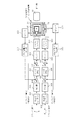
図14は、手ブレ量の検出回路とブレ補正回路の構成例を示すブロック図である。垂直方向の角速度を検出する第1角速度センサ301と水平方向の角加速度を検出する第2角速度センサ302には、積分器303、304、加減算器305、306、サーボ回路307、308、加算器317、318、ドライバ309、310を順次介してアクチュエータ(Y)311とアクチュエータ(X)312とに接続されている。アクチュエータ(Y)311は、前記撮像素子駆動機構21の撮像素子20が固定されたY方向スライダ34を駆動し、アクチュエータ(X)312は、X方向スライダ28を駆動する。光センサ313、314は、各々Y方向スライダ34とX方向スライダ28の位置に応じた信号を出力し、補正位置(Y)検出部315、補正位置(X)検出部316は、光センサ313、314からの信号に基づき、Y方向スライダ34とX方向スライダ28の位置を示す信号を前記加減算器305、306に入力する。また、加算器317、318には、あおりシフト量(Y)の設定値とあおりシフト量(X)の設定値とが入力される。
FIG. 14 is a block diagram illustrating a configuration example of a camera shake amount detection circuit and a shake correction circuit. The first
係る構成において、第1角速度センサ301と第2角速度センサ302で手ブレなどで生じたプレ量を逐次検出し、積分器303、304からの検出されたプレ量の積分値と、フィードバック信号として現在の補正量とがサーボ回路307、308に入力され、プレ量の積分値と補正量との差が小さくなるようにサーボ制御された信号がドライバー(駆動回路)309、310に出力され、アクチュエータ(Y)311とアクチュエータ(X)312が各スライダ34、28をX、Y方向に駆動し、撮像素子20が移動駆動される。あおり撮影をする場合には、さらに±のあおり量を加算した信号がドライバー309、310に加えられ、X,Y各方向のあおり量だけ、変心した位置を中心にプレ補正される。なお、これらの制御をマイコンによるソフトウェア制御で行ってもよい。
In such a configuration, the first
図15、16は、前記角速度センサ16、17の具体的構成例を示す図である。図15は、三角柱の音片型振動ジャイロ400を示すものであり、三角柱の振動子にはエリンバー等の恒弾性金属401が用いられ、これに圧電セラミックス402、端子403〜405を設けた構成である。この音片型振動ジャイロ400は、発振回路406、位相補正回路4040、差動増幅器408、同期検波器409、直流増幅器410に接続されて回路構成される。かかる音片型振動ジャイロ400を用いることにより、共振型の高感度の利点を生かしながら、振動方向の稜線のトリミングにより振動姿勢や他辺に影響を与えずに共振周波数を調整できる利点がある。そして、一辺a、長さl、質量m、ヤング率Y、密度ρの振動子の共振周波数frは、
fr=(m2a/4πl2)√(Y/6ρ)等で求めることができる。
15 and 16 are diagrams showing specific configuration examples of the
fr = (m 2 a / 4πl 2 ) √ (Y / 6ρ) or the like.
図16は、セラミックバイモルフ振動子を用いた圧電式の振動ジャイロ501であり、支持ピン(兼リード線)501a、圧電素子502を有している。この振動ジャイロ501は、HPF502、LPF503等に接続されて回路構成される。
FIG. 16 shows a
これらの振動ジャイロでは、図15(C)、図16(C)に示す回路によって、回転によって生じるコリオリの力を圧電素子で電圧信号に変換し、角速度に比例した電圧を検出できる。手振れ検出では、3Hz〜20Hz程度のブレの発生頻度が高く、応答性:50Hz、検出範囲:±360deg/s程度の超小型センサが利用できる。周囲温度の変化による静止時出力の温度ドリフトを除去するために、センサー出力に(カットオフ周波数fc=0.3〜0.5Hz程度の)HPF(ハイパスフィルタ)を接続してDC成分を除去し、また、センサ内部の振動ノイズ(20〜25kHz付近)等を除去するために、応答周波数以上の高周波成分を除去する(fc=1k〜数kHz程度の)LPF(ローパスフィルタ)を接続する。手ブレによる振動をジャイロにより角速度信号として検出し、A/D変換器でデジタル信号に変換し、マイコン回路などで積分演算して変位角度に変換し、角速度及び/又は変位角度に基づいてプレ補正量を決定し、撮像素子駆動機構21を駆動すればよい。
In these vibrating gyros, the circuit shown in FIGS. 15C and 16C can convert the Coriolis force generated by the rotation into a voltage signal by the piezoelectric element, and detect a voltage proportional to the angular velocity. In camera shake detection, a blurring frequency of about 3 Hz to 20 Hz is high, and an ultra-small sensor with a response of 50 Hz and a detection range of about ± 360 deg / s can be used. In order to remove the temperature drift of the stationary output due to the change of the ambient temperature, an HPF (high pass filter) (with a cut-off frequency fc = 0.3 to 0.5 Hz) is connected to the sensor output to remove the DC component. In addition, in order to remove vibration noise (around 20 to 25 kHz) and the like inside the sensor, an LPF (low pass filter) that removes high frequency components higher than the response frequency (from fc = 1 k to several kHz) is connected. Vibration caused by camera shake is detected as an angular velocity signal by a gyro, converted to a digital signal by an A / D converter, integrated by a microcomputer circuit and converted to a displacement angle, and pre-corrected based on the angular velocity and / or displacement angle. The amount may be determined and the image
(第3の実施の形態) (Third embodiment)
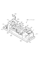
図17は、本発明の第3の実施の形態におけるデジタルカメラ1に搭載されるレンズユニット600の構成を示す斜視図である。図に示すように、レンズユニット600はズームユニット基板601を有し、このズームユニット基板601上には、相対向する起立部材602、603が立設されている。この起立部材602、603間には、一方側にガイドレール604が架装され、他方側にスクリューからなるズーム駆動用リードスクリュー605とフォーカス駆動用リードスクリュー606とが回転自在に架装されている。ガイドレール604には、フォーカス移動体607とズーム移動体608の一端部が摺動自在に外嵌され、ズーム駆動用リードスクリュー605にはズーム移動体608の他端部が螺合され、フォーカス駆動用リードスクリュー606にはフォーカス移動体607の他端部が螺合あされている。フォーカス移動体607とズーム移動体608及び一方の起立部材603には、光軸を同一にするレンズ609が設けられており、他方の起立部材602には、貫通穴610が設けられている。
FIG. 17 is a perspective view showing a configuration of a lens unit 600 mounted on the digital camera 1 according to the third embodiment of the present invention. As shown in the drawing, the lens unit 600 has a
また、ズームユニット基板601上には、ズーム駆動用リードスクリュー605を回転駆動するズーム駆動用モータ&ギア611と、フォーカス駆動用リードスクリュー606を駆動するフォーカス駆動用モータ&ギア612とが設けられている。したがって、このズーム駆動用モータ&ギア611とフォーカス駆動用モータ&ギア612の動作に伴って、ズーム駆動用リードスクリュー605とフォーカス駆動用リードスクリュー606とが回転することにより、フォーカス移動体607とズーム移動体608とが個別に前後移動するように構成されている。
Further, on the
また、前記起立部材602の外側上部には、外部からの光が入射する前記受光窓7(図1(A)参照)が設けられており、この受光窓7の下部には、回転式ミラー駆動機構614が配置されている。この回転式ミラー駆動機構614は、図18に示すように、垂直なYaw回転軸615に上下中央部を固定されたYaw回転ジンバル616と、このYaw回転ジンバル616の左右中央部に設けられたPitch回転軸617と、このPitch回転軸617に両側中央部を固定されて、Yaw回転ジンバル616内に配置されたPitch回転ジンバル618とが設けられ、このPitch回転ジンバル618にミラー619が配置されている。そして、Yaw駆動用VCM(ボイスコイルモータ)アクチュエータ620のムーバーとYaw回転軸615間に設けられたラック&ピニオン(図示せず)により、ムーバーが左右方向に直線移動することにより、Yaw回転ジンバル616がYaw回転軸615を中心に回転駆動される。また、Pitch駆動用VCMアクチュエータ621のムーバーとPitch回転軸617間に設けられたラック&ピニオン(図示せず)により、ムーバーが上下方向に直線移動することにより、Pitch回転ジンバル618がPitch回転軸617を中心に回転駆動されるように構成されている。
Further, the light receiving window 7 (see FIG. 1A) through which light from the outside is incident is provided on the outer upper portion of the standing
また、図17に示した他方の起立部材603の内部には、図19に示す撮像素子傾斜回転駆動機構622が設けられている。この撮像素子傾斜回転駆動機構622には、垂直なY回転軸623に下部中央を固定された傾斜&回転ジンバル624と、この傾斜&回転ジンバル624の左右中央部に設けられた傾斜回転軸625と、この傾斜回転軸625に両側中央部を固定されて、傾斜&回転ジンバル624内に配置された撮像素子取付部630とが設けられ、この撮像素子取付部630に撮像素子20が固定されている。そして、Y回転軸623は、減速歯車626を介してステップモータ627により回転駆動され、傾斜回転軸625は減速歯車628を介してステップモータ269により回転駆動されるように構成されている。
In addition, an imaging element tilt
そして、前記回転式ミラー駆動機構614と撮像素子傾斜回転駆動機構622の電気系統は、図17に示したフレキシブル配線を介して、制御部に接続される。なお、この第3の実施の形態におけるデジタルカメラ1の回路構成は、図4に示した第1及び第2の実施の形態とほぼ同様であるが、主制御部42により制御される撮影制御部52により、回転式ミラー駆動機構614と撮像素子傾斜回転駆動機構622の動作が制御される回路構成である。
The electrical system of the rotary
図20は、本発明の第2の実施の形態における動作を示すフローチャートであり、図4に示した主制御部42がプログラムメモリ47に格納されているプログラムに基づき各部を制御することにより、デジタルカメラ1は図20に示すフローチャートに示すように動作する。先ず、ユーザによる操作入力部40での操作に応じて、撮影モードを設定するとともに、複数のAF枠から選択されたAF枠の設定やストロボの発光条件等の撮影条件を設定する(ステップS301)。また、ユーザによる操作入力部40での操作により、ティルト/スィング撮影モードが設定されているか否かを判断し(ステップS302)、ティルト/スィング撮影モードが設定されていない場合には、その他の撮影モード処理に移行する(ステップS303)。ティルト/スィング撮影モードが設定されている場合には、測光処理、WB処理を実行するとともに(ステップS304)、ズーム処理、AF処理を実行した後(ステップS305)、被写体像のスルー画像を表示部14に表示させる(ステップS306)。すなわち、受光窓7をより入射されてミラー619により反射され、複数のレンズ609により撮像素子20に結像された被写体像のスルー画像を表示部14に表示させる。したがって、ユーザはこの表示部14に表示されたスルー画像を見ながら、このデジタルカメラ1の向きを調整する。
FIG. 20 is a flowchart showing the operation in the second embodiment of the present invention. The
次に、ティルト/スィング撮影モードにおける「自動ティルト/スィング」が設定されているか否かを判断する(ステップS307)。「自動ティルト/スィング」が設定されておらず、「手動ティルト/スィング」が設定されている場合には、ユーザによる操作入力部40での操作に応じて、ティルト/スィング角(傾斜回転角)φ設定する(ステップS308)。また、「自動ティルト/スィング」が設定されている場合には、レンズ面とピントを合わせたい被写体面との交点S(3面交会線)までの距離(L)、焦点距離(f)情報などを計測又は入力(ユーザの操作入力部40での操作よる入力)させる(ステップS309)。引き続き、下記例示式により、撮像素子20のティルト/スィング角(傾斜回転角)φを算出して設定する(ステップS310)。
(例)φ=tan−1(f/L)]
Next, it is determined whether or not “auto tilt / swing” in the tilt / swing shooting mode is set (step S307). When “automatic tilt / swing” is not set and “manual tilt / swing” is set, the tilt / swing angle (tilt rotation angle) is set according to the operation of the
(Example) φ = tan −1 (f / L)]
さらに、このステップS310又は前記ステップS308で設定されたティルト/スィング角(傾斜回転角)φに応じて、撮像素子傾斜回転駆動機構622により撮像素子20を傾斜回転させる(ステップS311)。次に、レリーズ釦3が半押しされたか否かを判断し(ステップS312)、レリーズ釦3が半押しされるまでステップS304からの処理を繰り返す。そして、ユーザがレリーズ釦3を半押しすると、ステップS312の判断がYESとなる。したがって、ステップS312からステップS313に進み、測光処理を行って、前記ステップS301で設定された撮影条件と、この測光処理により得られた測光値とに応じて、露出条件を設定する(ステップS313)。
Further, the
次に、手ブレ補正撮影モードが設定されている否かを判断し(ステップS314)、手ブレ補正撮影モード設定されていない場合には、ステップS315の処理を行うことなくステップS315に進む。手ブレ補正撮影モードが設定されている場合には、両角速度センサ16、17等からなるブレ検出回路により検出されている当該デジタルカメラ1の垂直方向及び水平方向のブレ量の検出を開始する(ステップS315)。また、中央及び上下(又は左右)のAF枠が共に合焦するように、AF処理を実行する(ステップS316)。つまり、ティルト/スィング撮影モードが設定されている場合には、前記ステップS306で表示部14にスルー画像を表示する際に、表示部14の中央及び上下左右にAF枠を表示し、この央及び上下(又は左右)のAF枠内の画像が合焦するように、AF処理を実行する。
Next, it is determined whether or not the camera shake correction shooting mode is set (step S314). If the camera shake correction shooting mode is not set, the process proceeds to step S315 without performing the process of step S315. When the camera shake correction shooting mode is set, detection of the shake amount in the vertical direction and the horizontal direction of the digital camera 1 detected by the shake detection circuit including the both
引き続き、レリーズ釦3が全押しされたか否かを判断し(ステップS317)、レリーズ釦3が全押しされるまで待機する。そして、ユーザが半押ししていたレリーズ釦3を全押しすると、ステップS317の判断がYESとなる。したがって、ステップS317からステップS318に進み、前記ステップS313で設定された撮影条件が示す設定露出時間に従って、露出時間タイマーを設定し、タイマー計時を開始する(ステップS333)。また、再度手ブレ補正撮影モードが設定されている否かを判断し(ステップS319)、手ブレ補正撮影モード設定されていない場合には、ステップS320及びS321の処理を行うことなくステップS322に進む。
Subsequently, it is determined whether or not the
手ブレ補正撮影モードが設定されている場合には、両角速度センサ16、17により検出されている当該デジタルカメラ1の垂直方向及び水平方向のブレ量(角速度)を検出する(ステップS320)。そして、この検出したブレ量の積分値(ブレ角度)θに応じて、回転式ミラー駆動機構614によりミラー619を(−θ/2)回転駆動する(ステップS321)。また、撮影条件に応じて露出(露光)及び撮影処理を実行し(ステップS322)、前記露出タイマーにより計時している露出時間が終了となったか否か、つまり露出タイマーの残時間が「0」となったか否かを判断する(ステップS323)。露出時間が終了となってない場合には、ステップS319に戻って、このステップS319からの処理を繰り返し実行する。そして、露出時間が終了し露出タイマーの残存時間が「0」となった場合には、撮影画像データを圧縮、符号化し(ステップS324)、この圧縮、符号化した撮影画像をメモリ(外部メモリ媒体62又はディスク媒体94)に記録する(ステップS325)。さらに、撮影画像を表示部14にレビュー表示し(ステップS326)、撮像素子駆動機構21により撮像素子20を初期位置(中央)に戻す(ステップS327)。
When the camera shake correction shooting mode is set, the blur amount (angular velocity) in the vertical direction and the horizontal direction of the digital camera 1 detected by the both
以上の第3の実施の形態において、予め「ティルト、又はスィング」について説明すると、ティルトでは、光輪に対して、前後方向にレンズ又は撮像面を傾けて撮影して、ピント状態を修正したり、歪みの矯正ができる。奥行きのある被写体を斜め上から撮影する場合、ピント面は撮像面と平行に生じ、限られた範囲しかピントは合わないが、レンズ側をピントを合わせたい面の傾きに合わせて(被写体面の延長線と撮像面の延長線との交点に向けて、レンズ面の延長線が交わるように)傾けると、絞りを変えることなく被写体全体にピントを合わせることができる。また、逆に傾ければ、ピント範囲を極端に狭めた写真も撮影できる。スィングでは、光輪に対して垂直な線を軸にしてレンズ面又は撮像面を(左右に)傾斜回転させ、左右に奥行きのある複数の被写体にピントを合せたり、遠近感を変更できる。 In the third embodiment described above, “tilt or swing” will be described in advance. In the tilt, the lens or the imaging surface is tilted in the front-rear direction with respect to the halo, and the focus state is corrected. Can correct distortion. When shooting a subject with a depth from above, the focus surface is parallel to the imaging surface and the focus is limited to a limited range, but the lens side is aligned with the tilt of the surface to be focused (on the subject surface). By tilting toward the intersection of the extension line and the extension line of the imaging surface (so that the extension line of the lens surface intersects), the entire subject can be focused without changing the aperture. You can also take a picture with the focus range extremely narrowed by tilting in the opposite direction. In the swing, the lens surface or the imaging surface is tilted and rotated (left and right) about a line perpendicular to the halo, so that a plurality of subjects having depths on the left and right can be focused or the perspective can be changed.
そして、本実施の形態においては、図21に示すように、撮像素子20の撮像面を光軸に垂直の面に対して、上下にティルト傾斜させて撮影する場合、あるいは、図22に示すように、撮像素子20の撮像面を光軸に垂直の輪の周りに左右にスィング傾斜させて撮影する場合には、大判カメラのティルト、及び、スィングの撮影技法ではよく知られる様に、「シャインプルーク(Scheimpflug)の法則」(又は、「3面交会の条件」)に従って、被写体面の延長面と、レンズ主面の延長面と、撮像面の延長面とが1線(S)で交わるようにすると、被写体面全体にピントが合わせられる。
In the present embodiment, as shown in FIG. 21, the imaging surface of the
本実施の形態では、図21、22に示すように、被写体面の延長面とレンズ主面の延長面が交わる交線に撮像面の延長面が交わるように、撮像面のチルト傾斜角やスィング傾斜角を制御すれば、絞りが開放でも、手前から奥まで被写体面全体、すなわち図の点A、B、Cにピントが合わせられる。ただし、この場合には、各点A、B、Cでは倍率が異なるので、像には被写体が歪んで写る。このとき、被写体平面全体にピントを合せる(合焦させる)ための傾斜角(ティルト/スィング角)φは、撮像面−レンズ主面一被写体平面が交会する交点(線)をSとすると、撮像面中心から3面交会線である交点Sまでの距離をJ、又は、レンズ中心から交点Sまでの距離をLとすると、次式で表わされる。
傾斜角φ=sin−1(焦点距離f/撮像面中心と3面交会線(交点S)との距離J)、
又は
傾斜角φ=tan−1(焦点距離f/レンズ中心と3面交会線(交点S)との距離L)
In the present embodiment, as shown in FIGS. 21 and 22, the tilt angle of the imaging surface and the swing are set so that the extended surface of the imaging surface intersects the intersection line where the extended surface of the subject surface and the extended surface of the lens main surface intersect. If the tilt angle is controlled, the entire object surface, that is, points A, B, and C in the figure, can be focused from the front to the back even when the aperture is fully open. However, in this case, since the magnification is different at each of the points A, B, and C, the subject appears distorted in the image. At this time, the tilt angle (tilt / swing angle) φ for focusing (focusing) on the entire subject plane is defined as S, where the intersection (line) where the subject plane meets the subject plane on the lens main surface is S. If the distance from the center of the surface to the intersection S, which is a three-plane intersection line, is J, or L is the distance from the center of the lens to the intersection S, it is expressed by the following equation.
Inclination angle φ = sin −1 (focal length f / distance J between imaging surface center and three-plane intersection line (intersection point S)),
Or inclination angle φ = tan −1 (focal length f / distance L between lens center and three-plane intersection line (intersection point S))
このように、撮像素子の傾斜回転機構を用いて、光輪に垂直な通常の撮像面に対して、撮像素子面をティルトやスィングさせて撮影するあおり撮影(あおり撮影(2)という)を行うことにより、遠近感や像の歪みを制御し、またピント状態を制御することによって、独特の表現の画像が撮影できる。 As described above, tilting and swinging the imaging device surface with respect to a normal imaging surface perpendicular to the halo using the tilting and rotating mechanism of the imaging device is used to perform tilt shooting (referred to as tilt shooting (2)). Therefore, by controlling the perspective and distortion of the image, and controlling the focus state, an image with a unique expression can be taken.
そして、本実施の形態において、被写体面前面にピントを合わせるように、あおり量(ティルト角やスィング角)を自動設定する場合には、上述のように、被写体面の延長線とカメラ又はレンズ面の延長線が交わる交点に撮像面の延長線が交わるように、
傾斜角φ=sin−1(焦点距離f/撮像面中心と3面交会線(交点S)との距離J)、
すなわち、
傾斜角φ=tan−1(焦点距離f/レンズ中心と3面交会線(交点S)との距離L)
となるように、撮像面の傾斜角φを制御すればよい。
In this embodiment, when the tilt amount (tilt angle or swing angle) is automatically set so as to focus on the front surface of the subject surface, as described above, the extension line of the subject surface and the camera or lens surface So that the extension line of the imaging plane intersects the intersection where the extension line of
Inclination angle φ = sin −1 (focal length f / distance J between imaging surface center and three-plane intersection line (intersection point S)),
That is,
Inclination angle φ = tan −1 (focal length f / distance L between lens center and three-plane intersection line (intersection point S))
The inclination angle φ of the imaging surface may be controlled so that
勿論、所定の被写体A,Bなどを選択して、当該被写体までの(鉛直又は水平方向の)距離や角度から、当該被写体A,Bを通る被写体面又はその延長面と、カメラ又はレンズ主面又はその延長面とが交会する直線S(3面交会線)の距離及び角度、又は、簡易には(鉛直又は水平方向の)交点Sの距離及び角度を求め、それに応じて、レンズ中心と3面交会線(交点S)との(鉛直又は水平方向の)距離Lを自動計算して、(鉛直又は水平方向の)傾斜角φを設定するようにしてもよい。あるいは、図2のカメラの外観構成図におけるカーソルキー10などにより、手動であおり量(ティルト角やスィング角)をそれぞれ操作してあおり撮影してもよい。
Of course, a predetermined subject A, B, etc. is selected, and from the distance or angle (vertical or horizontal) to the subject, the subject surface passing through the subject A, B or its extended surface, and the camera or lens main surface Alternatively, the distance and angle of the straight line S (three-plane intersection line) where the extended surface intersects, or simply the distance and angle of the intersection S (vertical or horizontal) are obtained, and the
なお、ビューカメラやフィールドカメラによる平面被写体の斜め写真撮影で被写体面の全面にピントを合せるには、「撮像面−レンズ面一被写体平面の3つの平面が1本の直線で交会していなければならない」という条件があり、これは、「シャインプルークの条件」又は「三面交会の条件」と呼ばれる。 In addition, in order to focus on the entire surface of the subject surface when shooting an oblique photograph of a planar subject using a view camera or a field camera, “If the three planes of the imaging plane—the lens plane and the subject plane do not meet on a single straight line, There is a condition of “not to be”, and this is called “the condition of Shine-Pluke” or “the condition of three-way party”.
また、図23の(A)に示す手ブレの無い状態から、(B)に示す手ブレが乗じた状態となった際には、前記ステップS321での処理により、(C)に示すように、手ブレ量θに応じて、ミラー619を−θ/2(逆方向)だけ回転させることにより、手ブレを補正した状態を形成することができる。さらに、図24の(A)であおり撮影(2)により、撮像素子20の撮像面を所定角度φだけ傾けてあおり撮影(ティルト撮影)を行っている状態で手ブレが生じた際には、同図(B)に示すように、あおり撮影(2)+手ブレ補正により、撮像素子20の撮像面を所定角度φだけ傾けてあおり撮影(ティルト撮影)を行いつつ、検出ブレ量θに応じてミラー619を−θ/2(逆方向)だけ、ダイナミックに回転させてブレ補正することもできる。
When the camera shake shown in (B) is multiplied from the camera shake-free state shown in (A) of FIG. 23, as shown in (C) by the processing in step S321. By rotating the
なお、実施の形態において、図1、2に示した外部構造のデジタルカメラ1に本発明を適用するようにしたが、これに限ることなく、静止画撮影機能を備えた携帯電話、大型のデジタルカメラ、本体と蓋体とからなり一方にLCDファインダーを備え他方にモニターを備える二つ折りのデジタルカメラ、ユーザの操作により当該ユーザ自身を撮影可能なデジタルカメラ等、他の構造からなる撮像装置、あるいは撮像機能を備えた携帯電話等の各種機器に本発明を適用することができる。 In the embodiment, the present invention is applied to the digital camera 1 having the external structure shown in FIGS. 1 and 2. However, the present invention is not limited to this, and is not limited to this. An imaging device having another structure such as a camera, a two-fold digital camera comprising an LCD finder on one side and a monitor on the other side, a digital camera capable of photographing the user itself by a user operation, or The present invention can be applied to various devices such as a mobile phone having an imaging function.
1 デジタルカメラ
2 本体
3 レリーズ釦
14 表示部
16 第1角速度センサ
16 第2角速度センサ
17 第2角速度センサ
20 撮像素子
21 撮像素子駆動機構
23 X方向ガイドレール
24 X方向駆動スクリュー
25 減速歯車
26 X方向駆動用モータ
27 駆動歯車
28 X方向スライダ
29 Y方向ガイドレール
30 Y方向駆動スクリュー
31 減速歯車
32 Y方向駆動用モータ
33 駆動歯車
34 Y方向スライダ
40 操作入力部
41 入力回路
42 主制御部
43 CPU
47 プログラムメモリ
48 データメモリ
201 撮像素子駆動機構
600 レンズユニット
614 回転式ミラー駆動機構
622 撮像素子傾斜回転駆動機構
DESCRIPTION OF SYMBOLS 1
47
Claims (11)
この撮像手段を駆動して前記撮像面に沿った方向に変位させる駆動手段と、
カメラ本体のブレを検出するブレ検出手段と、
このブレ検出手段により検出される前記カメラ本体のブレに基づき、前記駆動手段を制御し前記撮像手段を変位させるブレ補正制御手段と、
設定モードに応じて前記駆動手段を制御し、前記撮像手段を変位させるとともに当該変位させた位置に定位させる撮影制御手段と、
を備えることを特徴とする電子カメラ。 An imaging unit having an imaging surface for imaging a subject image formed by an optical system;
Driving means for driving the imaging means to displace it in a direction along the imaging surface;
Blur detection means for detecting camera shake,
Based on the blur of the camera body detected by the blur detection means, the blur correction control means for controlling the driving means and displacing the imaging means;
An imaging control unit that controls the driving unit according to a setting mode to displace the imaging unit and to localize the displaced position;
An electronic camera comprising:
この反射手段を駆動して反射角度を変化させる第1の駆動手段と、
前記光学系により結像される被写体像を撮像する撮像面を有する撮像手段と、
この撮像手段を駆動して前記撮像面を角度変化させる第2の駆動手段と、
カメラ本体のブレを検出するブレ検出手段と、
このブレ検出手段により検出される前記カメラ本体のブレに基づき、前記第1の駆動手段を制御し前記反射手段を角度変化させるブレ補正制御手段と、
設定モードに応じて前記第2の駆動手段を制御し、前記撮像手段を角度変化させるとともに当該角度変化させた位置に定位させる撮影制御手段と、
を備えることを特徴とする電子カメラ。 Reflection means for reflecting light from the outside to the optical system;
First driving means for driving the reflecting means to change the reflection angle;
Imaging means having an imaging surface for imaging a subject image formed by the optical system;
Second driving means for driving the imaging means to change the angle of the imaging surface;
Blur detection means for detecting camera shake,
A blur correction control means for controlling the first driving means and changing the angle of the reflecting means based on the blur of the camera body detected by the blur detection means;
Shooting control means for controlling the second driving means in accordance with a setting mode to change the angle of the imaging means and to localize the angle changed position;
An electronic camera comprising:
このモード設定手段により第1のモードが設定されている状態においては、前記ブレ補正制御手段を動作させ、前記第2のモードが設定されている状態においては、前記撮影制御手段を動作させる動作制御手段を更に備えることを特徴とする請求項1、2又は3記載の電子カメラ。 Mode setting means for selectively setting the first and second modes;
When the first mode is set by the mode setting means, the blur correction control means is operated, and when the second mode is set, the photographing control means is operated. 4. The electronic camera according to claim 1, further comprising means.
前記動作制御手段は、前記第3のモードが設定されている状態においては、前記撮影制御手段を動作させた状態で前記ブレ補正制御手段を動作させることを特徴とする請求項4記載の電子カメラ。 The mode setting means further selectively sets the third mode,
5. The electronic camera according to claim 4, wherein the motion control means operates the blur correction control means in a state where the photographing control means is operated in a state where the third mode is set. .
外部からの光を前記光学系に反射させる反射手段と、
この反射手段を駆動して反射角度を変化させる第1の駆動手段と、
前記光学系により結像される被写体像を撮像する撮像面を有する撮像手段と、
この撮像手段を駆動して前記撮像面を角度変化させる第2の駆動手段と、
を備えることを特徴とするレンズユニット。
Optical system,
Reflecting means for reflecting light from the outside to the optical system;
First driving means for driving the reflecting means to change the reflection angle;
Imaging means having an imaging surface for imaging a subject image formed by the optical system;
Second driving means for driving the imaging means to change the angle of the imaging surface;
A lens unit comprising:
Priority Applications (1)
| Application Number | Priority Date | Filing Date | Title |
|---|---|---|---|
| JP2006207496A JP2008035308A (en) | 2006-07-31 | 2006-07-31 | Electronic camera and lens unit |
Applications Claiming Priority (1)
| Application Number | Priority Date | Filing Date | Title |
|---|---|---|---|
| JP2006207496A JP2008035308A (en) | 2006-07-31 | 2006-07-31 | Electronic camera and lens unit |
Publications (2)
| Publication Number | Publication Date |
|---|---|
| JP2008035308A true JP2008035308A (en) | 2008-02-14 |
| JP2008035308A5 JP2008035308A5 (en) | 2009-09-10 |
Family
ID=39124250
Family Applications (1)
| Application Number | Title | Priority Date | Filing Date |
|---|---|---|---|
| JP2006207496A Pending JP2008035308A (en) | 2006-07-31 | 2006-07-31 | Electronic camera and lens unit |
Country Status (1)
| Country | Link |
|---|---|
| JP (1) | JP2008035308A (en) |
Cited By (16)
| Publication number | Priority date | Publication date | Assignee | Title |
|---|---|---|---|---|
| JP2010117591A (en) * | 2008-11-13 | 2010-05-27 | Nikon Corp | Imaging device |
| JP2010130633A (en) * | 2008-12-01 | 2010-06-10 | Nikon Corp | Imaging apparatus |
| US8743181B2 (en) | 2011-03-04 | 2014-06-03 | Olympus Corporation | Image pickup apparatus |
| JP2015070337A (en) * | 2013-09-26 | 2015-04-13 | 株式会社エフネット | Imaging apparatus, imaging method and program |
| JP2015106144A (en) * | 2013-12-03 | 2015-06-08 | 株式会社エフネット | Imaging apparatus |
| JP2017098613A (en) * | 2015-11-18 | 2017-06-01 | キヤノン株式会社 | Imaging apparatus, its control method, and control program |
| JP2017122791A (en) * | 2016-01-06 | 2017-07-13 | キヤノン株式会社 | Optical controller, optical instrument and optical control program |
| JP2017220864A (en) * | 2016-06-09 | 2017-12-14 | キヤノン株式会社 | Imaging apparatus and imaging program |
| US10084963B2 (en) | 2015-11-30 | 2018-09-25 | Ricoh Imaging Company, Ltd. | Stage apparatus, image projector apparatus having stage apparatus, and imaging apparatus having stage apparatus |
| US10142546B2 (en) | 2016-03-16 | 2018-11-27 | Ricoh Imaging Company, Ltd. | Shake-correction device and shake-correction method for photographing apparatus |
| US10341567B2 (en) | 2016-03-16 | 2019-07-02 | Ricoh Imaging Company, Ltd. | Photographing apparatus |
| US10432862B2 (en) | 2015-11-30 | 2019-10-01 | Ricoh Imaging Company, Ltd. | Imaging apparatus, image projector apparatus, and stage apparatus |
| EP3606042A1 (en) * | 2018-07-31 | 2020-02-05 | Canon Kabushiki Kaisha | Control apparatus, imaging apparatus, and program |
| EP3644601A1 (en) * | 2018-10-26 | 2020-04-29 | Canon Kabushiki Kaisha | Imaging apparatus and monitoring system |
| CN113395447A (en) * | 2021-05-31 | 2021-09-14 | 江西晶浩光学有限公司 | Anti-shake mechanism, image pickup device, and electronic apparatus |
| JP2022026134A (en) * | 2020-07-30 | 2022-02-10 | 富士フイルム株式会社 | Image pickup device |
Citations (8)
| Publication number | Priority date | Publication date | Assignee | Title |
|---|---|---|---|---|
| JPS63197926A (en) * | 1987-02-12 | 1988-08-16 | Canon Inc | Optical device |
| JPH0115258Y2 (en) * | 1981-11-11 | 1989-05-08 | ||
| JPH0389222A (en) * | 1989-08-31 | 1991-04-15 | Minolta Camera Co Ltd | Shift camera |
| JP2001094841A (en) * | 1999-09-21 | 2001-04-06 | Asahi Optical Co Ltd | Digital still camera having camera movements function |
| JP2002277736A (en) * | 2001-03-21 | 2002-09-25 | Olympus Optical Co Ltd | Image pickup device |
| JP2002325199A (en) * | 2001-04-25 | 2002-11-08 | Ricoh Co Ltd | Electronic imaging device |
| JP2004219930A (en) * | 2003-01-17 | 2004-08-05 | Minolta Co Ltd | Camera with camera-shake correction function |
| JP2005352240A (en) * | 2004-06-11 | 2005-12-22 | Olympus Corp | Optical system |
-
2006
- 2006-07-31 JP JP2006207496A patent/JP2008035308A/en active Pending
Patent Citations (8)
| Publication number | Priority date | Publication date | Assignee | Title |
|---|---|---|---|---|
| JPH0115258Y2 (en) * | 1981-11-11 | 1989-05-08 | ||
| JPS63197926A (en) * | 1987-02-12 | 1988-08-16 | Canon Inc | Optical device |
| JPH0389222A (en) * | 1989-08-31 | 1991-04-15 | Minolta Camera Co Ltd | Shift camera |
| JP2001094841A (en) * | 1999-09-21 | 2001-04-06 | Asahi Optical Co Ltd | Digital still camera having camera movements function |
| JP2002277736A (en) * | 2001-03-21 | 2002-09-25 | Olympus Optical Co Ltd | Image pickup device |
| JP2002325199A (en) * | 2001-04-25 | 2002-11-08 | Ricoh Co Ltd | Electronic imaging device |
| JP2004219930A (en) * | 2003-01-17 | 2004-08-05 | Minolta Co Ltd | Camera with camera-shake correction function |
| JP2005352240A (en) * | 2004-06-11 | 2005-12-22 | Olympus Corp | Optical system |
Cited By (25)
| Publication number | Priority date | Publication date | Assignee | Title |
|---|---|---|---|---|
| JP2010117591A (en) * | 2008-11-13 | 2010-05-27 | Nikon Corp | Imaging device |
| JP2010130633A (en) * | 2008-12-01 | 2010-06-10 | Nikon Corp | Imaging apparatus |
| US8743181B2 (en) | 2011-03-04 | 2014-06-03 | Olympus Corporation | Image pickup apparatus |
| JP2015070337A (en) * | 2013-09-26 | 2015-04-13 | 株式会社エフネット | Imaging apparatus, imaging method and program |
| JP2015106144A (en) * | 2013-12-03 | 2015-06-08 | 株式会社エフネット | Imaging apparatus |
| JP2017098613A (en) * | 2015-11-18 | 2017-06-01 | キヤノン株式会社 | Imaging apparatus, its control method, and control program |
| US10084963B2 (en) | 2015-11-30 | 2018-09-25 | Ricoh Imaging Company, Ltd. | Stage apparatus, image projector apparatus having stage apparatus, and imaging apparatus having stage apparatus |
| US10432862B2 (en) | 2015-11-30 | 2019-10-01 | Ricoh Imaging Company, Ltd. | Imaging apparatus, image projector apparatus, and stage apparatus |
| JP2017122791A (en) * | 2016-01-06 | 2017-07-13 | キヤノン株式会社 | Optical controller, optical instrument and optical control program |
| US10345615B2 (en) | 2016-01-06 | 2019-07-09 | Canon Kabushiki Kaisha | Optical control apparatus, optical apparatus, and storage medium for storing optical control program |
| US10142546B2 (en) | 2016-03-16 | 2018-11-27 | Ricoh Imaging Company, Ltd. | Shake-correction device and shake-correction method for photographing apparatus |
| US10341567B2 (en) | 2016-03-16 | 2019-07-02 | Ricoh Imaging Company, Ltd. | Photographing apparatus |
| JP2017220864A (en) * | 2016-06-09 | 2017-12-14 | キヤノン株式会社 | Imaging apparatus and imaging program |
| US10911688B2 (en) | 2018-07-31 | 2021-02-02 | Canon Kabushiki Kaisha | Control apparatus, imaging apparatus, and storage medium |
| JP2020020901A (en) * | 2018-07-31 | 2020-02-06 | キヤノン株式会社 | Control device, image capturing device, and program |
| EP3606042A1 (en) * | 2018-07-31 | 2020-02-05 | Canon Kabushiki Kaisha | Control apparatus, imaging apparatus, and program |
| JP7207888B2 (en) | 2018-07-31 | 2023-01-18 | キヤノン株式会社 | CONTROL DEVICE, IMAGING DEVICE, CONTROL METHOD OF CONTROL DEVICE, AND PROGRAM |
| EP3644601A1 (en) * | 2018-10-26 | 2020-04-29 | Canon Kabushiki Kaisha | Imaging apparatus and monitoring system |
| CN111107263A (en) * | 2018-10-26 | 2020-05-05 | 佳能株式会社 | Image pickup apparatus and monitoring system |
| CN111107263B (en) * | 2018-10-26 | 2022-04-19 | 佳能株式会社 | Image pickup apparatus and monitoring system |
| US11399126B2 (en) | 2018-10-26 | 2022-07-26 | Canon Kabushiki Kaisha | Imaging apparatus and monitoring system for performing a focus control and an angle control |
| JP2022026134A (en) * | 2020-07-30 | 2022-02-10 | 富士フイルム株式会社 | Image pickup device |
| JP7266561B2 (en) | 2020-07-30 | 2023-04-28 | 富士フイルム株式会社 | Imaging device |
| CN113395447A (en) * | 2021-05-31 | 2021-09-14 | 江西晶浩光学有限公司 | Anti-shake mechanism, image pickup device, and electronic apparatus |
| CN113395447B (en) * | 2021-05-31 | 2023-04-04 | 江西晶浩光学有限公司 | Anti-shake mechanism, image pickup device, and electronic apparatus |
Similar Documents
| Publication | Publication Date | Title |
|---|---|---|
| JP2008035308A (en) | Electronic camera and lens unit | |
| JP4622882B2 (en) | Digital camera | |
| JP4441565B2 (en) | Imaging device | |
| US9769384B2 (en) | Imaging apparatus capable of detecting position of movable image pickup device at first resolving power and at second resolving power higher than first resolving power and, at which second resolving power, deviation amount is less than or equal to pixel shift amount | |
| JP4968885B2 (en) | IMAGING DEVICE AND ITS CONTROL METHOD, IMAGING SYSTEM, IMAGE PROCESSING METHOD, AND PROGRAM | |
| JP2006171528A (en) | Driving mechanism, driving device, vibration correction unit, and imaging apparatus | |
| JP2005003719A (en) | Photographing device | |
| JP4875971B2 (en) | Image capturing apparatus and adjustment method thereof | |
| JP2008160175A (en) | Digital camera | |
| JP2009036986A (en) | Photographing device and control method for photographing device | |
| JP2010518443A (en) | A device that provides a stable image with a handheld camera | |
| JP2008003130A (en) | Image stabilizing apparatus and photographing apparatus | |
| JP5203657B2 (en) | Camera with enlarged display function | |
| JP2008054062A (en) | Image pickup device | |
| JP2009244490A (en) | Camera, camera control program and camera control method | |
| JP2009036985A (en) | Photographing device and control method for photographing device | |
| JP2006091106A (en) | Imaging apparatus and its control method | |
| JP5458521B2 (en) | Lens barrel, lens barrel adjustment method, optical device, and optical device adjustment method | |
| JP2003091027A (en) | Photographing device | |
| JP2012042589A (en) | Image shake correction mechanism, lens barrel, and image sensor | |
| JP2012159796A (en) | Focus adjustment device and imaging apparatus | |
| JP2006220834A (en) | Imaging apparatus | |
| JP5027029B2 (en) | Camera with enlargement display function and camera control method | |
| JP2008107731A (en) | Lens device, imaging apparatus, digital camera and portable telephone | |
| JP2008070566A (en) | Camera system, camera body, interchangeable lens unit and image blur correction method |
Legal Events
| Date | Code | Title | Description |
|---|---|---|---|
| A521 | Request for written amendment filed |
Free format text: JAPANESE INTERMEDIATE CODE: A523 Effective date: 20090724 |
|
| A621 | Written request for application examination |
Free format text: JAPANESE INTERMEDIATE CODE: A621 Effective date: 20090724 |
|
| A977 | Report on retrieval |
Free format text: JAPANESE INTERMEDIATE CODE: A971007 Effective date: 20110127 |
|
| A131 | Notification of reasons for refusal |
Free format text: JAPANESE INTERMEDIATE CODE: A131 Effective date: 20110208 |
|
| A521 | Request for written amendment filed |
Free format text: JAPANESE INTERMEDIATE CODE: A523 Effective date: 20110406 |
|
| A131 | Notification of reasons for refusal |
Free format text: JAPANESE INTERMEDIATE CODE: A131 Effective date: 20110726 |
|
| A02 | Decision of refusal |
Free format text: JAPANESE INTERMEDIATE CODE: A02 Effective date: 20120110 |