JP2008024206A - Control device for controlling power supply of mobile body - Google Patents
Control device for controlling power supply of mobile body Download PDFInfo
- Publication number
- JP2008024206A JP2008024206A JP2006200567A JP2006200567A JP2008024206A JP 2008024206 A JP2008024206 A JP 2008024206A JP 2006200567 A JP2006200567 A JP 2006200567A JP 2006200567 A JP2006200567 A JP 2006200567A JP 2008024206 A JP2008024206 A JP 2008024206A
- Authority
- JP
- Japan
- Prior art keywords
- power
- power supply
- mobile
- mobile body
- ground
- Prior art date
- Legal status (The legal status is an assumption and is not a legal conclusion. Google has not performed a legal analysis and makes no representation as to the accuracy of the status listed.)
- Granted
Links
Images


Abstract
Description
本発明は、列車鉄道システム、新交通システム、物流システムなど、走行路上を走行する移動体の電力供給を管理制御する移動体電力供給管理制御装置に関する。 The present invention relates to a mobile power supply management control device that manages and controls power supply of a mobile body that travels on a traveling path, such as a train railway system, a new transportation system, and a logistics system.
本発明は、列車鉄道システム、新交通システム、物流システムなど、走行路上を走行する車両、例えば、列車、自動車、搬送車などの移動体は、地上電力供給設備(変電所)から電力を供給されて走行している。以下、移動体として鉄道システムの車両を例に採り説明する。 In the present invention, a vehicle traveling on a road such as a train railway system, a new transportation system, and a logistics system, for example, a moving body such as a train, an automobile, and a transportation vehicle is supplied with electric power from a ground power supply facility (substation). Running. Hereinafter, a railway system vehicle will be described as an example of the moving body.
図7は列車鉄道システムの説明図である。列車鉄道システムでは停車場がホーム1a、1bであり、車両2a、2bが走行路3a、3bを走行する。列車運行のための電力は、変電所4から架線などの電力線を通じて車両2a、2bに供給され、列車は予め定められた運転ダイヤに基づいて運転される。列車の運転は、標準車両の車両特性に基づいて作成される運転曲線に沿ってなされる。運転曲線は、列車の各位置に対する列車速度や運転ノッチ操作を規定したものである。
FIG. 7 is an explanatory diagram of the train railway system. In the train railway system, the stops are the homes 1a and 1b, and the
変電所4では運転ダイヤに見合う電力を列車に供給できるよう電力機器の設定がなされているが、運転ダイヤの本数増加などの経年にわたる運用の変更や、車両故障などに起因する運転ダイヤの乱れに対して、必ずしも、常に十分で余剰のない電力供給がなされるとは限らない。特に、変電所から遠い末端の区間では電力供給が十分でない場合も発生し得る。 In substation 4, power equipment is set up so that it can supply the train with electric power commensurate with the driving schedule. However, due to changes in operation over time, such as an increase in the number of driving schedules, and disruption of driving schedules due to vehicle breakdowns, etc. On the other hand, there is not always a sufficient and surplus power supply. In particular, the power supply may not be sufficient in the end section far from the substation.
これらに対して、変電所にサイリスタ整流器を設置し、き電電圧の制御を行うという試みもある。現在では、限られた一部の変電所では手動で実施しているものの中央の電力管理システムとの間でダイナミックに電力制御を実施するようなことは行われていない。 On the other hand, there is an attempt to control a feeding voltage by installing a thyristor rectifier in a substation. At present, although some limited substations are manually implemented, power control is not performed dynamically with a central power management system.
一方、最近では、回生ブレーキを使用する車両が多く、回生ブレーキは回生できない場合には失効しエネルギーはロスとなる。また、機械ブレーキが作動するために、メンテナンス上も改善の余地がある。そのため、車両内に蓄電装置を設置する列車の開発が進められている。 On the other hand, recently, there are many vehicles that use a regenerative brake, and when the regenerative brake cannot be regenerated, it expires and the energy is lost. In addition, since the mechanical brake operates, there is room for improvement in terms of maintenance. For this reason, development of trains that install power storage devices in vehicles is underway.
ここで、電力を利用して走行路上を移動する列車が利用する電力を蓄電する電力貯蔵手段の貯蔵残電力を計測し、検出された残電力量等に基づいて列車の走行計画を立て、最適かつ安全性に富んだ列車等の走行体の制御を行うようにしたものがある(例えば、特許文献1参照)。
しかし、変電所からの給電が十分でない場合には、電車線の電圧低下により、列車が所望の速度を出せないので、その結果所要時間が増大し遅延がよりひどくなることがある。また、列車を同時に複数台起動できなくなり起動に制約が課せられることがある。 However, when the power supply from the substation is not sufficient, the train cannot produce the desired speed due to the voltage drop of the train line, and as a result, the required time increases and the delay may become worse. In addition, a plurality of trains cannot be started at the same time, and restrictions may be imposed on the start-up.
また、変電所の容量以上に列車本数を増加させることができないので、列車本数を増加させるためには電力供給設備の増強が必要であるが、供給電力を1割増程度を行うにも多くのコストが発生する。 In addition, since the number of trains cannot be increased beyond the capacity of the substation, it is necessary to reinforce the power supply facilities in order to increase the number of trains. Will occur.
本発明の目的は、移動体の全体での電力管理を行うことができ、省エネルギーを実現し運行の乱れの防止や機器の最適化を図ることができる移動体電力供給管理制御装置を提供することにある。 An object of the present invention is to provide a mobile power supply management control device that can perform power management for the entire mobile body, realize energy saving, prevent disturbance of operation, and optimize equipment. It is in.
本発明の移動体電力供給管理制御装置は、地上電力供給設備を用いて移動体に電力を供給するき電装置があり、移動体の一部に蓄電装置を備え、移動体が集電した電力と蓄電装置に内蔵の電力を利用して走行路上を移動する移動体に供給する電力を管理制御する移動体電力供給管理制御装置において、移動体の運行をつかさどる運転ダイヤと移動体の位置とに基づいて移動体運行のための所要電力を予測し予想所要電力を前記地上電力供給設備の間で最適に配分するための電力管理システムと、前記電力管理システムで配分された電力供給指示に基づいて地上電力供給設備から前記移動体への供給電力を制御する地上電力制御装置と、前記電力管理システムで配分された電力供給指示に基づいて前記移動体への供給電力を制御する移動体電力制御装置と、
を備えたことを特徴とする。
The mobile power supply management control device of the present invention includes a power feeder that supplies power to a mobile using ground power supply equipment, and includes a power storage device in a part of the mobile, and the power collected by the mobile In the mobile power supply management control device that manages and controls the power supplied to the moving body moving on the traveling path using the power built in the power storage device, the operation diagram that controls the operation of the moving body and the position of the moving body A power management system for predicting the required power for mobile operation based on this and optimally allocating the expected required power among the ground power supply facilities, and based on a power supply instruction distributed by the power management system A ground power control device that controls power supplied from a ground power supply facility to the mobile body, and a mobile power that controls power supplied to the mobile body based on a power supply instruction distributed by the power management system And a control device,
It is provided with.
本発明によれば、移動体の全体での電力管理を行うことができ、省エネルギーを実現し運行の乱れの防止や機器の最適化を図ることができる。 ADVANTAGE OF THE INVENTION According to this invention, the power management of the whole mobile body can be performed, energy saving can be implement | achieved, the disturbance of operation can be prevented, and the optimization of an apparatus can be aimed at.
図1は本発明の実施の形態に係わる移動体電力供給管理制御装置のブロック構成図である。図1では、都市内の鉄道や民鉄などに採用されている直流き電システムに適用した場合を示している。路線トータルの電力を管理するシステムとして、地上に電力管理システム11を設置する。電力管理システム11は電力管理システム中央装置11aと電力管理システム子局11bとからなる。電力管理システム中央装置11aは、列車の運行を管理する運行管理システム12とLAN13で結合されている。これにより、全列車の位置は、運行管理システム12で認識しているものをリアルタイムに電力管理システム11で利用できるようになっている。
FIG. 1 is a block diagram of a mobile power supply management control apparatus according to an embodiment of the present invention. FIG. 1 shows a case where the present invention is applied to a DC feeder system employed in urban railways and private railways. A power management system 11 is installed on the ground as a system for managing the total power of the route. The power management system 11 includes a power management system
地上電力供給設備(変電所)14には電力管理システム子局11bが設置され、これらは、電力管理システム11のLAN15で結合されている。電力管理システム子局11bは、必ずしも地上電力供給設備14に設置される必要はなく、地上電力供給設備14以外の場所に設置可能である。電力管理システム子局11bの間は、地上のLAN設備でなく無線ネットワークで構成されてもよい。
A power management
地上電力供給設備14には、電力会社や自営の発電所から交流で送電されてくる電力を受電する受電端と交流母線16、直流で電車にき電するための直流母線17、交流から直流に変換するための変換器18、ならびに変換器18を制御するための地上電力制御装置19が設置されている。
The ground
移動体(車両)20は、き電装置21を介して地上電力供給設備14の直流母線17から電力の供給を受ける。また、移動体20は蓄電装置22及び移動体電力制御装置24を備え、移動体電力制御装置24は、移動体20が集電した電力と蓄電装置22に内蔵の電力を制御してて走行路23上を移動する。
The mobile body (vehicle) 20 is supplied with power from the DC
電力管理システム11は、移動体20の運行をつかさどる運転ダイヤと移動体20の位置とに基づいて移動体20の運行のための所要電力を予測し、予想所要電力を地上電力供給設備14や移動体20内の蓄電装置22との間で最適に配分する。地上電力制御装置19は、電力管理システム11で配分された電力供給指示に基づいて変換器18を制御し、地上電力供給設備14から移動体20への供給電力を制御する。また、移動体電力制御装置24は、電力管理システム14で配分された電力供給指示の情報を地上−車上情報伝送装置25を介して受信し、受信した配分された電力供給指示に基づいて移動体20内の蓄電装置22から移動体20への供給電力を制御する。
The power management system 11 predicts the required power for the operation of the
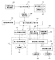
図2は電力管理システム11の構成図である。図2において、電力管理システム11では、移動体位置検出装置26で検出されたすべての移動体(列車)20の位置と運行管理システム12で決定する運転ダイヤ37を用いて全移動体20の走行予測を行う。
FIG. 2 is a configuration diagram of the power management system 11. In FIG. 2, in the power management system 11, the travel of all the
移動体20の位置検出方法としては、移動体位置検出装置26で検出することに代えて、運行管理システム12から入手する方法がある。また、移動体位置検出装置26としては、移動体20内に発信器を搭載し、走行路内に分散する移動体20の位置を把握する方法、移動体20にGPSやTGを搭載し、移動体20が自己の移動体20の位置を検出し、車上−地上伝送により電力管理システム11に情報を集める方式などが考えられる。
As a method for detecting the position of the moving
走行予測手段27は、運行管理システム12から入力した移動体20の運行をつかさどる運転ダイヤと、移動体位置検出装置26で検出した移動体20の位置とに基づいて将来の移動体20の走行を予測する。所要電力予測手段28は、走行予測手段27で得られた走行予測結果に基づき、一定期間の移動体20を走行させるのに必要な所要電力を予測する。
The travel predicting means 27 predicts the future travel of the
図3は運転ダイヤのダイヤグラムの説明図である。この運転ダイヤのダイヤグラムに基づき、走行予測について説明する。図3の横軸は時刻であり、縦軸は移動体20の位置である。移動体20は、図3の上からもしくは下から右方向に進行する。現在時刻t1から右側が予測結果である。移動体20の走行を、移動体20の遅延も考慮してある予測期間T1に亘って運転ダイヤや運転曲線データなどを使用して予測する。移動体20の遅延がなければ、運転ダイヤに従ってスジをのばせばよい。遅延があれば平行移動するか予め計算しておいた遅延回復時間を使ってスジを立たせる。
所要電力予測手段28は、このようにして得られた走行予測結果に基づき、所要電力を予測する。通常、移動体(列車)20の運転は運転曲線で規定される。運転曲線には、モータを駆動して加速する力行やだ行、ブレーキ走行といったノッチ操作が計画され、これらが記載されており、これと移動体20の所要電力特性とから所要電力が計算できる。
FIG. 3 is an explanatory diagram of a diagram of the driving diagram. Based on this driving diagram, the travel prediction will be described. The horizontal axis in FIG. 3 is time, and the vertical axis is the position of the
The required power prediction means 28 predicts the required power based on the travel prediction result obtained in this way. Usually, the operation of the moving body (train) 20 is defined by an operation curve. In the running curve, notching operations such as power running and running to accelerate by driving the motor, and brake running are planned, and these are described, and the required power can be calculated from this and the required power characteristics of the moving
電力供給最適化計算手段29は、所要電力予測手段28で得られた所要電力を複数の地上電力供給設備14の間で最適に配分するものである。電力供給最適配分の方法として、スケジュール運転とリアルタイム運転とによる配分がある。スケジュール運転では、移動体20に遅延がない場合、つまり、移動体20が運行ダイヤに沿って運転できるときは、予め、運転ダイヤと運転曲線、所要電力特性データを用いて、オフラインで各時間帯の各地上電力供給設備14の最適な運転方法を決定しておき、それを各地上電力制御装置19や移動体電力制御装置24に内蔵させ制御を実行させるものである。
The power supply
一方、リアルタイム運転では、所要電力予測値に基づき、電力供給最適配分を計算することによって、地上電力供給設備14のき電電圧目標値を算出し、移動体20で集電をするかしないかの判断を決定する。時々刻々の地上電力供給設備14の電圧・電流・電力を電気量検出装置30で計測し、その計測値と照らし合わせて各地上電力供給設備14の運転を決定する。
On the other hand, in real-time operation, whether or not the
そして、地上情報伝送装置31を介して地上電力制御装置19に指令を出力するとともに、地上−車上情報伝送装置25を介して移動体電力制御装置24に指令を出力する。移動体20で集電をしないとの判断である場合には、き電切り離し装置32によりき電装置21が切り離される。移動体20で集電をするかしないかの状態は、移動体電力制御装置24を介して、移動体20の運行を管理する移動体運行管理装置33に入力される。
Then, a command is output to the ground
図4は移動体20の構成図である。移動体20は、き電装置21から電力の供給を受けるとともに蓄電装置22からの電力の供給を受け、運転計画作成手段34で作成された運転計画に基づいて、移動体電力制御装置24により駆動装置35に電力を供給し移動体20を走行させる。また、減速装置36からの回生電力を蓄電装置22に蓄電する。運転計画作成手段34は、運転ダイヤ37、路線データベース38、車両性能データベース39に基づき運転計画を作成する。
FIG. 4 is a configuration diagram of the moving
蓄電装置22の電力の残量は残電力検出手段40で検出され、移動体電力制御装置24に入力される。これにより、移動体電力制御装置24は蓄電装置22の供給可能な残電力を監視している。また、移動体電力制御装置24には移動体運行管理装置33が接続されており移動体運行管理装置33により移動体20の運行が管理される。移動体20の速度は速度認識手段41で検出され、また、移動体20の位置は位置検出手段42で検出され、それぞれ移動体電力制御装置24に入力され、移動体20の走行制御に用いられる。さらに、移動体電力制御装置24は伝送手段43を介して、地上電力供給設備14の地上−車上情報伝送装置25と通信を行うようになっている。
The remaining power of the
次に、電力供給最適化計算手段29での最適化計算について説明する。最適化計算は最適化のためのシステムの定式化を行い、いわゆる最適化手法に基づき演算する方法がある。ここでは、オフラインで電力供給分担を設定し、データベース化して使用する場合について説明する。 Next, optimization calculation by the power supply optimization calculation means 29 will be described. Optimization calculation involves formulating a system for optimization and performing a calculation based on a so-called optimization technique. Here, a case will be described in which power supply sharing is set off-line and used as a database.
図5は、電力供給最適化計算手段29に予め記憶される電力配分テーブルの一例の説明図である。図5では3つのケースA、B、Cを示している。電力配分内容としては、「各地上電力供給設備(変電所)のき電電圧設定値のパターン」と「移動体のき電からの切離しをする/しない」とがあり、これらのパターンの組合せを予めケースA、B、Cに割り振っておく。ケースAは地上電力供給設備のき電電圧設定値のパターンがP1で、き電の切り離しが無の場合、ケースBは地上電力供給設備のき電電圧設定値のパターンがP2で、き電の切り離しが無の場合、ケースCは地上電力供給設備のき電電圧設定値のパターンがP3で、き電の切り離しが有の場合を示している。
FIG. 5 is an explanatory diagram of an example of a power distribution table stored in advance in the power supply
図6は、地上電力供給設備のき電電圧設定値のパターンがP1、P2、P3の説明図である。図6のにおいて、SS1は第1の地上電力供給設備、SS2は第2の地上電力供給設備、SS3は第3の地上電力供給設備であり、き電電圧設定値のパターンP1は、標準のパターンを示しており、第1の地上電力供給設備SS1、第2の地上電力供給設備SS2、第3の地上電力供給設備SS3は、いずれも供給電圧は標準である場合のパターンである。き電電圧設定値のパターンP2は、第1の地上電力供給設備SS1及び第2の地上電力供給設備SS2の供給電圧は標準で、第2の地上電力供給設備SS2の供給電圧を高くした場合のパターンである。き電電圧設定値のパターンP3は、第1の地上電力供給設備SS1、第2の地上電力供給設備SS2、第3の地上電力供給設備SS3の供給電圧を高くした場合のパターンである。 FIG. 6 is an explanatory diagram for patterns P1, P2, and P3 of the feeding voltage setting value of the ground power supply facility. In FIG. 6, SS1 is a first ground power supply facility, SS2 is a second ground power supply facility, SS3 is a third ground power supply facility, and a feeding voltage setting value pattern P1 is a standard pattern. The first ground power supply facility SS1, the second ground power supply facility SS2, and the third ground power supply facility SS3 are all patterns when the supply voltage is standard. The feeding voltage set value pattern P2 is a case where the supply voltage of the first ground power supply facility SS1 and the second ground power supply facility SS2 is standard, and the supply voltage of the second ground power supply facility SS2 is increased. It is a pattern. The feeding voltage set value pattern P3 is a pattern when the supply voltages of the first ground power supply facility SS1, the second ground power supply facility SS2, and the third ground power supply facility SS3 are increased.
各々の地上電力供給設備SS1、SS2、SS3では、例えば変圧器のタップを切り替えて供給電圧を高くしたり、あるいは、サイリスタ整流器などを用いて供給電力を高くする。 In each terrestrial power supply facility SS1, SS2, SS3, for example, the tap of the transformer is switched to increase the supply voltage, or the supply power is increased using a thyristor rectifier or the like.
電力供給最適化計算手段29で算出した電力供給配分内容(き電電圧設定値やき電切離しの有無)は、ある固定もしくはイベントドリブンの制御タイミングで各地上電力供給設備の地上電力制御装置19や移動体電力制御装置24に送信される。電力管理システム11から各地上電力供給設備の地上電力制御装置19へは有線のLANでも無線伝送でもかまわない。移動体20への移動体通信として、ここでは、無線伝送を考える。情報量が小さければレールを介した伝送でもよい。
The power supply distribution content calculated by the power supply optimization calculation means 29 (feed voltage setting value and presence / absence of power supply disconnection) is determined based on the ground
地上電力供給設備14では、電力管理システム11から伝送された制御指令(き電電圧設定値のパターンP1、P2、P3)を受け取りき電電圧設定値を変更する。この際、ローカルで自己の地上電力供給設備ならびに他の地上電力供給設備の電圧・電流・電力・故障などの状態監視を行い、中央の指令値に対し変更を加えることもできる。
The ground
移動体20では、電力管理システム11から伝送された制御指令(き電切り離しの有無)を受け取り、き電を切離すか継続するかの制御を行う。この際、移動体20内の蓄電装置22の状態監視結果を考慮することもできる。
The
また、移動体20では、蓄電装置22の蓄電電力の残量の検出や故障などの状態監視を実施し、移動運行管理手段33に情報を伝送し、監視状態の表示や音声放送などを行う。また、伝送手段43を経由して、電力供給最適化計算手段29に情報を伝送する。電力供給最適化計算手段29での電力供給最適化計算において、移動体20の蓄電装置22の電力の残量や故障などの状態監視情報を使用する。さらに、これらの情報はメンテナンス情報として蓄積し、保守管理や故障解析などに活用することができる。
Further, the
このように、運行管理と電力管理とを統合的に管理することにより、また、伝送手段を統合/適正分担することにより、鉄道システム全体の効率化や省コスト化を図ることができ、さらに一元管理を行うことができる。 In this way, by managing the operation management and power management in an integrated manner, and by integrating / appropriately sharing the transmission means, it is possible to improve the efficiency and cost saving of the entire railway system. Management can be performed.
ここで、路線長が長くなく輸送力の大きくない地域交通では、通常、地上電力供給設備(変電所)は一箇所であり、地上電力供給設備14に電力管理システム11が設置されている。このような場合には、地上電力供給設備14の電圧制御と移動体20へのき電切離し指令とを以下のように実施する。
Here, in the regional traffic where the route length is not long and the transportation capacity is not large, the ground power supply facility (substation) is usually one place, and the power management system 11 is installed in the ground
まず、全移動体20の位置を移動体位置検出装置26で検出し、全移動体20の在線分布を把握し、き電電圧の分布をシミュレーションなどを使用して模擬し、き電電圧の分布を推定する。そして、き電電圧の低下している区間を走行する移動体20に対しては、集電せず蓄電装置22に蓄えた電力を使用して走行するように指令する。この場合、地上−車上情報伝送装置14としては、保安制御手段や運行管理手段で設置されているものを利用してもよい。また、列車無線を使用して、人間系で実施することも可能である。
First, the position of the entire moving
また、移動体20を走行させるにあたり、地上電力供給設備14に蓄電装置22を設置し、地上電力供給設備14に設置した蓄電装置22から移動体20に電力を供給するようにしてもよい。このようにすることにより、蓄電装置22を備えていない移動体20に対しても運行制御が可能となる。この場合、電力供給最適化計算手段29は、地上電力供給設備14に設置した蓄電装置22から供給できる電力も考慮して最適化計算を行うことになる。これにより、路線サイズに見合ったコンパクトな全体設計を行うことができる。
Further, when traveling the
次に、鉄道システムなどでは、運行ダイヤで輸送負荷を予め見込むことができる。従って、定常的もしくは慢性的な電力負荷バランスを予想することができる。このような場合には、以下のように移動体20を走行制御する。
Next, in a railway system or the like, the transportation load can be estimated in advance by an operation schedule. Therefore, a steady or chronic power load balance can be predicted. In such a case, traveling control of the moving
例えば、地上電力供給設備(変電所)が中央などにあり、路線の末端のターミナル駅において、移動体(車両)20が混雑し、き電電圧低下が見込まれるようなシステム構成においては、路線を複数の区間に分け、区間ごとに時間帯別に移動体20の蓄電装置22に蓄積された電力のみで走行する。
For example, in a system configuration where the ground power supply facility (substation) is in the center, etc., and the mobile unit (vehicle) 20 is congested at the terminal station at the end of the route and the feeder voltage is expected to drop, The vehicle is divided into a plurality of sections, and travels with only the electric power stored in the
このとき、運行ダイヤには時間帯による粗密がある場合があることから、時間帯により制御を分けるスケジュール運転を行う。すなわち、移動体20が予め定めた時間帯に予め定めた走行区間を走行するときは、移動体20内の蓄電装置22に蓄積された電力で移動体20を走行させる。また、初期システム設計において、末端部では初めから蓄電エネルギーを使用して走行し、末端駅などにおいて蓄電装置22に給電することを考慮することも可能である。
At this time, since there are cases in which the operation schedule is dense depending on the time zone, a schedule operation is performed in which the control is divided according to the time zone. That is, when the
この場合、移動体20は時間帯及び自己の位置を認識する必要があるので、時計手段及び位置検出手段を設ける。つまり、各々の移動体20に位置認識手段42を設け、この位置認識手段42で走行位置を検出し走行区間を識別する。また、移動体20で位置や区間を検出することに代えて地上側で位置もしくは区間検出を行い、各移動体20に伝送するようにしてもよい。
In this case, since the moving
さらに簡易な方法として、走行区間の検知ではなく、移動体20の地点通過情報を電力制御のトリガーとして利用するようにしてもよい。また、すべての移動体20には、蓄電装置22を搭載する必要はなく、蓄電装置22を搭載する車両と搭載しない移動体20の混在運転も可能である。蓄電装置22を搭載しない移動体20に対しては、例えば、地上電力供給設備(変電所)に設けた蓄電装置から電力を供給するようにする。これにより、簡便な方法で、既存の路線の輸送力拡大や新規路線の敷設を容易に行うことができる利点がある。
As a simpler method, the point passing information of the moving
このように、省エネルギーのために列車走行の駆動源である電力を移動体20の蓄電装置22に貯蔵し、ひいては架線によるき電を行わずして、例えば鉄道車両が自動車のように動力源をもった形で自在に走行することが可能となる。
In this way, to save energy, electric power, which is a driving source for train travel, is stored in the
このとき、対象とする走行路を走行する車両すべてに蓄電装置22を搭載する必要はなく、一部区間に電車線があり残りの区間に電車線がない場合も適用できる。電車線がない区間においては、移動体20の蓄電装置22に電力を供給する電力供給ポイントが設置し、その電力供給ポイントから移動体20の蓄電装置22に電力を供給することになる。
At this time, it is not necessary to mount the
本発明の実施の形態によれば、蓄電装置を一部の移動体20に搭載する鉄道システムあるいは新交通システム、自動運転バスシステムなど、路線上を走行する移動体20に対して、地上電力供給設備(変電所)からの供給電力の分担の最適化を図ることができ、トータルの電力使用量を抑制し、また定時性にも優れた運行を実現することができる。
According to the embodiment of the present invention, ground power is supplied to a
1…ホーム、2…車両、3…走行路、4…変電所、11…電力管理システム、12…運行管理システム、13…LAN、14…地上電力供給設備、15…LAN、16…交流母線、17…直流母線、18…変換器、19…地上電力制御装置、20…移動体、21…き電装置、22…蓄電装置、23…走行路、24…移動体電力制御装置、25…地上−車上情報伝送装置、26…移動体位置検出装置、27…走行予測手段、28…所要電力予測手段、29…電力供給最適化計算手段、30…電気量検出装置、31…地上情報伝送装置、32…き電切り離し装置、33…移動体運行管理装置、34…運転計画作成手段、35…駆動装置、36…減速装置、37…運転ダイヤ、38…路線データベース、39…車両性のデータベース、40…残電力検出手段、41…速度認識手段、42…位置認識手段、43…伝送手段
DESCRIPTION OF
Claims (10)
移動体の運行をつかさどる運転ダイヤと移動体の位置とに基づいて移動体運行のための所要電力を予測し予想所要電力を前記地上電力供給設備の間で最適に配分するための電力管理システムと、
前記電力管理システムで配分された電力供給指示に基づいて地上電力供給設備から前記移動体への供給電力を制御する地上電力制御装置と、
前記電力管理システムで配分された電力供給指示に基づいて前記移動体への供給電力を制御する移動体電力制御装置と、
を備えたことを特徴とする移動体電力供給管理制御装置。 There is a power feeder that supplies power to a mobile unit using ground power supply facilities. A part of the mobile unit has a power storage device, and the mobile unit uses the power collected by the mobile unit and the built-in power in the power storage device. In a mobile power supply management control device for managing and controlling power supplied to a mobile moving on the road,
A power management system for predicting the required power for moving the vehicle based on the driving schedule that controls the operation of the moving object and the position of the moving object, and optimally allocating the expected required power among the ground power supply facilities; ,
A ground power control device that controls power supplied from a ground power supply facility to the mobile unit based on a power supply instruction distributed by the power management system;
A mobile power control apparatus for controlling power supplied to the mobile based on a power supply instruction distributed by the power management system;
A mobile power supply management control device comprising:
移動体の運行をつかさどる運転ダイヤと移動体の位置とに基づいて将来の移動体の走行を予測し走行予測結果に基づき移動体運行のための所要電力を予測する所要電力予測手段と、
前記所要電力予測手段で得られた所要電力を複数の地上電力供給設備の間で最適に配分するための電力供給最適化計算手段と、
前記地上電力供給設備に対する電力供給指示を地上電力制御装置に伝送する地上情報伝送装置と、
前記移動体に対する電力供給指示を移動体電力制御装置に伝送する地上−車上情報伝送装置と、
を備えたことを特徴とする請求項1記載の移動体電力供給管理制御装置。 The power management system includes:
A required power predicting means for predicting a future travel of the mobile body based on a driving schedule for controlling the travel of the mobile body and a position of the mobile body and predicting a required power for the mobile body based on the travel prediction result;
Power supply optimization calculating means for optimally allocating the required power obtained by the required power prediction means among a plurality of ground power supply facilities;
A ground information transmission device that transmits a power supply instruction to the ground power supply facility to a ground power control device;
A ground-on-vehicle information transmission device for transmitting a power supply instruction to the mobile body to the mobile power control device;
The mobile power supply management control device according to claim 1, further comprising:
移動体の運行をつかさどる運転ダイヤと移動体の位置とに基づいて将来の移動体の走行を予測し走行予測結果に基づき移動体運行のための所要電力を予測する所要電力予測手段と、
前記地上電力供給設備のひとつもしくは複数のポイントにおける電力・電圧・電流を検出する電気量検出手段と、
前記電気量検出手段の検出値及び前記移動体の蓄電装置の電力の残量に基づいて前記所要電力予測手段で得られた所要電力を複数の地上電力供給設備の間で最適に配分するための電力供給最適化計算手段と、
前記地上電力供給設備に対する電力供給指示を地上電力制御装置に伝送する地上情報伝送装置と、
前記移動体においてき電を切り離すか否かの指示を移動体電力制御装置に伝送する地上−車上情報伝送装置と、
を備えたことを特徴とする移動体電力供給管理制御装置。 The power management system includes:
A required power predicting means for predicting a future travel of the mobile body based on a driving schedule for controlling the travel of the mobile body and a position of the mobile body and predicting a required power for the mobile body based on the travel prediction result;
An electric quantity detection means for detecting power, voltage, and current at one or more points of the ground power supply facility;
For optimally distributing the required power obtained by the required power prediction means based on the detection value of the electric quantity detection means and the remaining power of the power storage device of the mobile body among a plurality of ground power supply facilities Power supply optimization calculation means;
A ground information transmission device that transmits a power supply instruction to the ground power supply facility to a ground power control device;
A ground-on-vehicle information transmission device for transmitting an instruction to the mobile power control device whether or not to remove the feeding power in the mobile body;
A mobile power supply management control device comprising:
10. The vehicle according to claim 9, wherein instead of the predetermined travel section, when the mobile body passes a predetermined point passing point, the mobile body is caused to travel with the electric power stored in the power storage device in the mobile body. Mobile power supply management control device.
Priority Applications (1)
| Application Number | Priority Date | Filing Date | Title |
|---|---|---|---|
| JP2006200567A JP4909666B2 (en) | 2006-07-24 | 2006-07-24 | Feeding system |
Applications Claiming Priority (1)
| Application Number | Priority Date | Filing Date | Title |
|---|---|---|---|
| JP2006200567A JP4909666B2 (en) | 2006-07-24 | 2006-07-24 | Feeding system |
Publications (2)
| Publication Number | Publication Date |
|---|---|
| JP2008024206A true JP2008024206A (en) | 2008-02-07 |
| JP4909666B2 JP4909666B2 (en) | 2012-04-04 |
Family
ID=39115280
Family Applications (1)
| Application Number | Title | Priority Date | Filing Date |
|---|---|---|---|
| JP2006200567A Expired - Fee Related JP4909666B2 (en) | 2006-07-24 | 2006-07-24 | Feeding system |
Country Status (1)
| Country | Link |
|---|---|
| JP (1) | JP4909666B2 (en) |
Cited By (11)
| Publication number | Priority date | Publication date | Assignee | Title |
|---|---|---|---|---|
| JP2010068625A (en) * | 2008-09-10 | 2010-03-25 | Chugoku Electric Power Co Inc:The | Control device and control method of dc transmission/distribution system and program |
| WO2012111607A1 (en) * | 2011-02-18 | 2012-08-23 | 三菱重工業株式会社 | Analysis device of catenary-based transportation system, analysis method and program therefor |
| WO2013069518A1 (en) * | 2011-11-09 | 2013-05-16 | 三菱重工業株式会社 | Charging fee calculation device, charging fee calculation method, and program therefor |
| JP2013095398A (en) * | 2011-11-07 | 2013-05-20 | Hitachi Ltd | Monitoring and control system of electric railway |
| WO2013161882A1 (en) * | 2012-04-26 | 2013-10-31 | 日立建機株式会社 | Operation management system |
| WO2014002717A1 (en) * | 2012-06-25 | 2014-01-03 | 株式会社日立製作所 | Railway system |
| US8831801B1 (en) | 2013-03-14 | 2014-09-09 | Mitsubishi Electric Research Laboratories, Inc. | System and method for optimizing energy consumption in railway systems |
| JP2015036286A (en) * | 2013-08-14 | 2015-02-23 | 株式会社日立製作所 | Train operation management system and train operation simulation method |
| US9180790B2 (en) | 2012-02-22 | 2015-11-10 | Mitsubishi Electric Corporation | DC feeder voltage control apparatus and DC feeder voltage control system |
| JP2017121835A (en) * | 2016-01-05 | 2017-07-13 | 株式会社東芝 | Train battery control device, method and program |
| JP2019188887A (en) * | 2018-04-19 | 2019-10-31 | 三菱電機株式会社 | Direct-current feed voltage control device, direct-current feed voltage control method, and direct-current feed voltage control program |
Citations (3)
| Publication number | Priority date | Publication date | Assignee | Title |
|---|---|---|---|---|
| JPH07304353A (en) * | 1994-05-13 | 1995-11-21 | Toshiba Corp | Feeding voltage controller for railway substation |
| JPH10322905A (en) * | 1997-05-22 | 1998-12-04 | Mitsubishi Electric Corp | Contract power excess prevention device for railway substation |
| JP2005124291A (en) * | 2003-10-15 | 2005-05-12 | Toshiba Corp | Control unit and travel body equipped with the same |
-
2006
- 2006-07-24 JP JP2006200567A patent/JP4909666B2/en not_active Expired - Fee Related
Patent Citations (3)
| Publication number | Priority date | Publication date | Assignee | Title |
|---|---|---|---|---|
| JPH07304353A (en) * | 1994-05-13 | 1995-11-21 | Toshiba Corp | Feeding voltage controller for railway substation |
| JPH10322905A (en) * | 1997-05-22 | 1998-12-04 | Mitsubishi Electric Corp | Contract power excess prevention device for railway substation |
| JP2005124291A (en) * | 2003-10-15 | 2005-05-12 | Toshiba Corp | Control unit and travel body equipped with the same |
Cited By (24)
| Publication number | Priority date | Publication date | Assignee | Title |
|---|---|---|---|---|
| JP2010068625A (en) * | 2008-09-10 | 2010-03-25 | Chugoku Electric Power Co Inc:The | Control device and control method of dc transmission/distribution system and program |
| US9035495B2 (en) | 2011-02-18 | 2015-05-19 | Mitsubishi Heavy Industries, Ltd. | Analysis device of catenary-based transportation system, analysis method and program therefor |
| WO2012111607A1 (en) * | 2011-02-18 | 2012-08-23 | 三菱重工業株式会社 | Analysis device of catenary-based transportation system, analysis method and program therefor |
| JP2012171415A (en) * | 2011-02-18 | 2012-09-10 | Mitsubishi Heavy Ind Ltd | Analyzer and analyzing method of catenary-based transportation system, and program thereof |
| CN102971180A (en) * | 2011-02-18 | 2013-03-13 | 三菱重工业株式会社 | Analysis device of catenary-based transportation system, analysis method and program therefor |
| JP2013095398A (en) * | 2011-11-07 | 2013-05-20 | Hitachi Ltd | Monitoring and control system of electric railway |
| WO2013069518A1 (en) * | 2011-11-09 | 2013-05-16 | 三菱重工業株式会社 | Charging fee calculation device, charging fee calculation method, and program therefor |
| JP2013101554A (en) * | 2011-11-09 | 2013-05-23 | Mitsubishi Heavy Ind Ltd | Charging fee calculation apparatus, charging fee calculation method and program therefor |
| US9180790B2 (en) | 2012-02-22 | 2015-11-10 | Mitsubishi Electric Corporation | DC feeder voltage control apparatus and DC feeder voltage control system |
| US9452679B2 (en) | 2012-04-26 | 2016-09-27 | Hitachi Construction Machinery Co., Ltd. | Operation management system |
| JP2013230039A (en) * | 2012-04-26 | 2013-11-07 | Hitachi Constr Mach Co Ltd | Operation management system |
| DE112013002340B9 (en) | 2012-04-26 | 2023-06-22 | Hitachi Construction Machinery Co., Ltd. | operations management system |
| DE112013002340B4 (en) | 2012-04-26 | 2023-02-16 | Hitachi Construction Machinery Co., Ltd. | operations management system |
| CN104245407A (en) * | 2012-04-26 | 2014-12-24 | 日立建机株式会社 | Operation management system |
| WO2013161882A1 (en) * | 2012-04-26 | 2013-10-31 | 日立建機株式会社 | Operation management system |
| WO2014002717A1 (en) * | 2012-06-25 | 2014-01-03 | 株式会社日立製作所 | Railway system |
| JP2014004914A (en) * | 2012-06-25 | 2014-01-16 | Hitachi Ltd | Railroad system |
| CN104379397A (en) * | 2012-06-25 | 2015-02-25 | 株式会社日立制作所 | Railway system |
| JP2014177269A (en) * | 2013-03-14 | 2014-09-25 | Mitsubishi Electric Corp | System and method for optimizing energy consumption in railway system |
| US8831801B1 (en) | 2013-03-14 | 2014-09-09 | Mitsubishi Electric Research Laboratories, Inc. | System and method for optimizing energy consumption in railway systems |
| JP2015036286A (en) * | 2013-08-14 | 2015-02-23 | 株式会社日立製作所 | Train operation management system and train operation simulation method |
| JP2017121835A (en) * | 2016-01-05 | 2017-07-13 | 株式会社東芝 | Train battery control device, method and program |
| JP2019188887A (en) * | 2018-04-19 | 2019-10-31 | 三菱電機株式会社 | Direct-current feed voltage control device, direct-current feed voltage control method, and direct-current feed voltage control program |
| JP7049166B2 (en) | 2018-04-19 | 2022-04-06 | 三菱電機株式会社 | DC feeder voltage controller, DC feeder voltage control method, and DC feeder voltage control program |
Also Published As
| Publication number | Publication date |
|---|---|
| JP4909666B2 (en) | 2012-04-04 |
Similar Documents
| Publication | Publication Date | Title |
|---|---|---|
| JP4909666B2 (en) | Feeding system | |
| WO2010026786A1 (en) | Power feed control system, and power feed control method | |
| de la Fuente et al. | Railway electrical smart grids: An introduction to next-generation railway power systems and their operation | |
| CN100509471C (en) | Method and system for monitoring and regulating consumpted power of transport system | |
| JP2576719B2 (en) | Railway system | |
| JP2019004696A (en) | Method for performing load distribution of plural charging stations to movement load in charging station network and charging station network | |
| WO2013099171A1 (en) | Transportation management device, transportation management system, and control program | |
| CN101804823B (en) | Method and device for automatically controlling railway route entry | |
| JP6047827B2 (en) | Operation control device, operation control method, and control program | |
| CN105711618B (en) | Railway control system with on-board management | |
| KR102432480B1 (en) | Method and system for navigation of electric transport device based on power guide of energy storage charging pile | |
| JP2017165237A (en) | Train operation support system | |
| JP2015060570A (en) | Operation plan generation device and operation plan generation method | |
| KR20110038046A (en) | Power adjustment system adapted for powering an electric line for supplying power to vehicles | |
| EA025731B1 (en) | Method for controlling a powered system based on mission plan | |
| CN109398161A (en) | A kind of trackside signalling arrangement system in ATP automatic passing over of neutral section area | |
| JP5317620B2 (en) | Railway system | |
| JP3161154B2 (en) | Train operation management system | |
| JP2008161055A (en) | Motor car run system | |
| US9376034B2 (en) | Method for minimizing the electricity consumption required for a public transport network and associated algorithmic platform | |
| JP2012040954A (en) | System for supplying electric power for electric railroad | |
| RU2629622C1 (en) | System for controlling and monitoring power and energy consumed by transport system | |
| KR101497345B1 (en) | Method and system for compensation of railway power load using a fuel battery train | |
| JPH05176457A (en) | Power system controller for railway | |
| RU2811608C1 (en) | System for monitoring and regulating power and energy consumed by transport system |
Legal Events
| Date | Code | Title | Description |
|---|---|---|---|
| A621 | Written request for application examination |
Free format text: JAPANESE INTERMEDIATE CODE: A621 Effective date: 20090223 |
|
| A131 | Notification of reasons for refusal |
Free format text: JAPANESE INTERMEDIATE CODE: A131 Effective date: 20111004 |
|
| A521 | Request for written amendment filed |
Free format text: JAPANESE INTERMEDIATE CODE: A523 Effective date: 20111202 |
|
| TRDD | Decision of grant or rejection written | ||
| A01 | Written decision to grant a patent or to grant a registration (utility model) |
Free format text: JAPANESE INTERMEDIATE CODE: A01 Effective date: 20111220 |
|
| A01 | Written decision to grant a patent or to grant a registration (utility model) |
Free format text: JAPANESE INTERMEDIATE CODE: A01 |
|
| A61 | First payment of annual fees (during grant procedure) |
Free format text: JAPANESE INTERMEDIATE CODE: A61 Effective date: 20120116 |
|
| FPAY | Renewal fee payment (event date is renewal date of database) |
Free format text: PAYMENT UNTIL: 20150120 Year of fee payment: 3 |
|
| R151 | Written notification of patent or utility model registration |
Ref document number: 4909666 Country of ref document: JP Free format text: JAPANESE INTERMEDIATE CODE: R151 |
|
| FPAY | Renewal fee payment (event date is renewal date of database) |
Free format text: PAYMENT UNTIL: 20150120 Year of fee payment: 3 |
|
| LAPS | Cancellation because of no payment of annual fees |