JP2008020003A - Process for producing track member and valve gear, and track member - Google Patents
Process for producing track member and valve gear, and track member Download PDFInfo
- Publication number
- JP2008020003A JP2008020003A JP2006192994A JP2006192994A JP2008020003A JP 2008020003 A JP2008020003 A JP 2008020003A JP 2006192994 A JP2006192994 A JP 2006192994A JP 2006192994 A JP2006192994 A JP 2006192994A JP 2008020003 A JP2008020003 A JP 2008020003A
- Authority
- JP
- Japan
- Prior art keywords
- temperature
- cam follower
- region
- manufacturing
- hardness
- Prior art date
- Legal status (The legal status is an assumption and is not a legal conclusion. Google has not performed a legal analysis and makes no representation as to the accuracy of the status listed.)
- Pending
Links
Images


Classifications
-
- F—MECHANICAL ENGINEERING; LIGHTING; HEATING; WEAPONS; BLASTING
- F16—ENGINEERING ELEMENTS AND UNITS; GENERAL MEASURES FOR PRODUCING AND MAINTAINING EFFECTIVE FUNCTIONING OF MACHINES OR INSTALLATIONS; THERMAL INSULATION IN GENERAL
- F16C—SHAFTS; FLEXIBLE SHAFTS; ELEMENTS OR CRANKSHAFT MECHANISMS; ROTARY BODIES OTHER THAN GEARING ELEMENTS; BEARINGS
- F16C33/00—Parts of bearings; Special methods for making bearings or parts thereof
- F16C33/30—Parts of ball or roller bearings
- F16C33/58—Raceways; Race rings
- F16C33/64—Special methods of manufacture
-
- C—CHEMISTRY; METALLURGY
- C21—METALLURGY OF IRON
- C21D—MODIFYING THE PHYSICAL STRUCTURE OF FERROUS METALS; GENERAL DEVICES FOR HEAT TREATMENT OF FERROUS OR NON-FERROUS METALS OR ALLOYS; MAKING METAL MALLEABLE, e.g. BY DECARBURISATION OR TEMPERING
- C21D1/00—General methods or devices for heat treatment, e.g. annealing, hardening, quenching or tempering
- C21D1/06—Surface hardening
- C21D1/09—Surface hardening by direct application of electrical or wave energy; by particle radiation
- C21D1/10—Surface hardening by direct application of electrical or wave energy; by particle radiation by electric induction
-
- C—CHEMISTRY; METALLURGY
- C21—METALLURGY OF IRON
- C21D—MODIFYING THE PHYSICAL STRUCTURE OF FERROUS METALS; GENERAL DEVICES FOR HEAT TREATMENT OF FERROUS OR NON-FERROUS METALS OR ALLOYS; MAKING METAL MALLEABLE, e.g. BY DECARBURISATION OR TEMPERING
- C21D9/00—Heat treatment, e.g. annealing, hardening, quenching or tempering, adapted for particular articles; Furnaces therefor
- C21D9/40—Heat treatment, e.g. annealing, hardening, quenching or tempering, adapted for particular articles; Furnaces therefor for rings; for bearing races
-
- C—CHEMISTRY; METALLURGY
- C23—COATING METALLIC MATERIAL; COATING MATERIAL WITH METALLIC MATERIAL; CHEMICAL SURFACE TREATMENT; DIFFUSION TREATMENT OF METALLIC MATERIAL; COATING BY VACUUM EVAPORATION, BY SPUTTERING, BY ION IMPLANTATION OR BY CHEMICAL VAPOUR DEPOSITION, IN GENERAL; INHIBITING CORROSION OF METALLIC MATERIAL OR INCRUSTATION IN GENERAL
- C23C—COATING METALLIC MATERIAL; COATING MATERIAL WITH METALLIC MATERIAL; SURFACE TREATMENT OF METALLIC MATERIAL BY DIFFUSION INTO THE SURFACE, BY CHEMICAL CONVERSION OR SUBSTITUTION; COATING BY VACUUM EVAPORATION, BY SPUTTERING, BY ION IMPLANTATION OR BY CHEMICAL VAPOUR DEPOSITION, IN GENERAL
- C23C8/00—Solid state diffusion of only non-metal elements into metallic material surfaces; Chemical surface treatment of metallic material by reaction of the surface with a reactive gas, leaving reaction products of surface material in the coating, e.g. conversion coatings, passivation of metals
- C23C8/06—Solid state diffusion of only non-metal elements into metallic material surfaces; Chemical surface treatment of metallic material by reaction of the surface with a reactive gas, leaving reaction products of surface material in the coating, e.g. conversion coatings, passivation of metals using gases
- C23C8/28—Solid state diffusion of only non-metal elements into metallic material surfaces; Chemical surface treatment of metallic material by reaction of the surface with a reactive gas, leaving reaction products of surface material in the coating, e.g. conversion coatings, passivation of metals using gases more than one element being applied in one step
- C23C8/30—Carbo-nitriding
- C23C8/32—Carbo-nitriding of ferrous surfaces
-
- C—CHEMISTRY; METALLURGY
- C23—COATING METALLIC MATERIAL; COATING MATERIAL WITH METALLIC MATERIAL; CHEMICAL SURFACE TREATMENT; DIFFUSION TREATMENT OF METALLIC MATERIAL; COATING BY VACUUM EVAPORATION, BY SPUTTERING, BY ION IMPLANTATION OR BY CHEMICAL VAPOUR DEPOSITION, IN GENERAL; INHIBITING CORROSION OF METALLIC MATERIAL OR INCRUSTATION IN GENERAL
- C23C—COATING METALLIC MATERIAL; COATING MATERIAL WITH METALLIC MATERIAL; SURFACE TREATMENT OF METALLIC MATERIAL BY DIFFUSION INTO THE SURFACE, BY CHEMICAL CONVERSION OR SUBSTITUTION; COATING BY VACUUM EVAPORATION, BY SPUTTERING, BY ION IMPLANTATION OR BY CHEMICAL VAPOUR DEPOSITION, IN GENERAL
- C23C8/00—Solid state diffusion of only non-metal elements into metallic material surfaces; Chemical surface treatment of metallic material by reaction of the surface with a reactive gas, leaving reaction products of surface material in the coating, e.g. conversion coatings, passivation of metals
- C23C8/80—After-treatment
-
- F—MECHANICAL ENGINEERING; LIGHTING; HEATING; WEAPONS; BLASTING
- F01—MACHINES OR ENGINES IN GENERAL; ENGINE PLANTS IN GENERAL; STEAM ENGINES
- F01L—CYCLICALLY OPERATING VALVES FOR MACHINES OR ENGINES
- F01L1/00—Valve-gear or valve arrangements, e.g. lift-valve gear
- F01L1/12—Transmitting gear between valve drive and valve
- F01L1/18—Rocking arms or levers
- F01L1/181—Centre pivot rocking arms
-
- F—MECHANICAL ENGINEERING; LIGHTING; HEATING; WEAPONS; BLASTING
- F16—ENGINEERING ELEMENTS AND UNITS; GENERAL MEASURES FOR PRODUCING AND MAINTAINING EFFECTIVE FUNCTIONING OF MACHINES OR INSTALLATIONS; THERMAL INSULATION IN GENERAL
- F16C—SHAFTS; FLEXIBLE SHAFTS; ELEMENTS OR CRANKSHAFT MECHANISMS; ROTARY BODIES OTHER THAN GEARING ELEMENTS; BEARINGS
- F16C19/00—Bearings with rolling contact, for exclusively rotary movement
- F16C19/22—Bearings with rolling contact, for exclusively rotary movement with bearing rollers essentially of the same size in one or more circular rows, e.g. needle bearings
- F16C19/44—Needle bearings
- F16C19/46—Needle bearings with one row or needles
-
- F—MECHANICAL ENGINEERING; LIGHTING; HEATING; WEAPONS; BLASTING
- F01—MACHINES OR ENGINES IN GENERAL; ENGINE PLANTS IN GENERAL; STEAM ENGINES
- F01L—CYCLICALLY OPERATING VALVES FOR MACHINES OR ENGINES
- F01L1/00—Valve-gear or valve arrangements, e.g. lift-valve gear
- F01L1/12—Transmitting gear between valve drive and valve
- F01L1/14—Tappets; Push rods
- F01L1/146—Push-rods
-
- F—MECHANICAL ENGINEERING; LIGHTING; HEATING; WEAPONS; BLASTING
- F01—MACHINES OR ENGINES IN GENERAL; ENGINE PLANTS IN GENERAL; STEAM ENGINES
- F01L—CYCLICALLY OPERATING VALVES FOR MACHINES OR ENGINES
- F01L1/00—Valve-gear or valve arrangements, e.g. lift-valve gear
- F01L1/12—Transmitting gear between valve drive and valve
- F01L1/18—Rocking arms or levers
- F01L1/185—Overhead end-pivot rocking arms
-
- F—MECHANICAL ENGINEERING; LIGHTING; HEATING; WEAPONS; BLASTING
- F01—MACHINES OR ENGINES IN GENERAL; ENGINE PLANTS IN GENERAL; STEAM ENGINES
- F01L—CYCLICALLY OPERATING VALVES FOR MACHINES OR ENGINES
- F01L1/00—Valve-gear or valve arrangements, e.g. lift-valve gear
- F01L1/20—Adjusting or compensating clearance
-
- F—MECHANICAL ENGINEERING; LIGHTING; HEATING; WEAPONS; BLASTING
- F01—MACHINES OR ENGINES IN GENERAL; ENGINE PLANTS IN GENERAL; STEAM ENGINES
- F01L—CYCLICALLY OPERATING VALVES FOR MACHINES OR ENGINES
- F01L2301/00—Using particular materials
-
- F—MECHANICAL ENGINEERING; LIGHTING; HEATING; WEAPONS; BLASTING
- F01—MACHINES OR ENGINES IN GENERAL; ENGINE PLANTS IN GENERAL; STEAM ENGINES
- F01L—CYCLICALLY OPERATING VALVES FOR MACHINES OR ENGINES
- F01L2303/00—Manufacturing of components used in valve arrangements
-
- F—MECHANICAL ENGINEERING; LIGHTING; HEATING; WEAPONS; BLASTING
- F01—MACHINES OR ENGINES IN GENERAL; ENGINE PLANTS IN GENERAL; STEAM ENGINES
- F01L—CYCLICALLY OPERATING VALVES FOR MACHINES OR ENGINES
- F01L2305/00—Valve arrangements comprising rollers
-
- F—MECHANICAL ENGINEERING; LIGHTING; HEATING; WEAPONS; BLASTING
- F01—MACHINES OR ENGINES IN GENERAL; ENGINE PLANTS IN GENERAL; STEAM ENGINES
- F01L—CYCLICALLY OPERATING VALVES FOR MACHINES OR ENGINES
- F01L2800/00—Methods of operation using a variable valve timing mechanism
- F01L2800/18—Testing or simulation
-
- F—MECHANICAL ENGINEERING; LIGHTING; HEATING; WEAPONS; BLASTING
- F16—ENGINEERING ELEMENTS AND UNITS; GENERAL MEASURES FOR PRODUCING AND MAINTAINING EFFECTIVE FUNCTIONING OF MACHINES OR INSTALLATIONS; THERMAL INSULATION IN GENERAL
- F16C—SHAFTS; FLEXIBLE SHAFTS; ELEMENTS OR CRANKSHAFT MECHANISMS; ROTARY BODIES OTHER THAN GEARING ELEMENTS; BEARINGS
- F16C2360/00—Engines or pumps
- F16C2360/18—Camshafts
-
- Y—GENERAL TAGGING OF NEW TECHNOLOGICAL DEVELOPMENTS; GENERAL TAGGING OF CROSS-SECTIONAL TECHNOLOGIES SPANNING OVER SEVERAL SECTIONS OF THE IPC; TECHNICAL SUBJECTS COVERED BY FORMER USPC CROSS-REFERENCE ART COLLECTIONS [XRACs] AND DIGESTS
- Y02—TECHNOLOGIES OR APPLICATIONS FOR MITIGATION OR ADAPTATION AGAINST CLIMATE CHANGE
- Y02P—CLIMATE CHANGE MITIGATION TECHNOLOGIES IN THE PRODUCTION OR PROCESSING OF GOODS
- Y02P10/00—Technologies related to metal processing
- Y02P10/25—Process efficiency
-
- Y—GENERAL TAGGING OF NEW TECHNOLOGICAL DEVELOPMENTS; GENERAL TAGGING OF CROSS-SECTIONAL TECHNOLOGIES SPANNING OVER SEVERAL SECTIONS OF THE IPC; TECHNICAL SUBJECTS COVERED BY FORMER USPC CROSS-REFERENCE ART COLLECTIONS [XRACs] AND DIGESTS
- Y10—TECHNICAL SUBJECTS COVERED BY FORMER USPC
- Y10T—TECHNICAL SUBJECTS COVERED BY FORMER US CLASSIFICATION
- Y10T29/00—Metal working
- Y10T29/49—Method of mechanical manufacture
- Y10T29/49826—Assembling or joining
Abstract
Description
本発明は軌道部材の製造方法、動弁装置の製造方法および軌道部材に関し、より特定的には、その一部が塑性変形することにより隣接する部材に対して固定される軌道部材とその製造方法、および当該軌道部材を有するカムフォロアを備えた動弁装置の製造方法に関するものである。 TECHNICAL FIELD The present invention relates to a method for manufacturing a track member, a method for manufacturing a valve operating device, and a track member, and more specifically, a track member that is fixed to an adjacent member by plastic deformation of a part thereof, and a method for manufacturing the track member. And a method of manufacturing a valve gear including a cam follower having the track member.
一般に、転がり軸受は、外輪、内輪などの軌道部材と、当該軌道部材に接触して配置される玉、ころなどの転動体とを備えている。そして、転がり軸受は、軌道部材である内輪および外輪の少なくともいずれか一方が、当該軌道部材に隣接する他の部材に対して固定されて使用される。ここで、軌道部材の固定は、当該軌道部材を隣接する他の部材に対して嵌め込むことにより行なわれるほか、たとえばかしめ加工のように当該軌道部材の一部の領域を塑性変形させることにより行なわれる場合もある。 In general, a rolling bearing includes race members such as an outer ring and an inner ring, and rolling elements such as balls and rollers arranged in contact with the race member. In the rolling bearing, at least one of an inner ring and an outer ring, which are track members, is fixed to another member adjacent to the track member. Here, the race member is fixed by fitting the race member to another adjacent member, or by plastically deforming a part of the race member, for example, by caulking. There is also a case.
このような塑性変形を利用した軌道部材の固定は、嵌め込みによる固定に比べて、固定のための新たな部材を必要としないため、低コスト化およびコンパクト化が可能であることなどの利点を有している。一方、塑性変形を利用した軌道部材の固定を行なうためには、軌道部材における硬度分布に十分留意する必要がある。すなわち、塑性変形を利用した固定を行なう場合、軌道部材において塑性変形される領域は、塑性変形時の割れの発生を抑制する観点から、比較的低硬度、たとえば300HV以下の硬度を有する必要がある。これに対し、軌道部材において、転動体と接触する表面である転走面は、十分な転動疲労寿命を確保する観点から、高硬度、たとえは653HV(58HRC)以上の硬度を有する必要がある。 Fixing the raceway member using plastic deformation does not require a new member for fixing as compared to fixing by fitting, and thus has advantages such as low cost and compactness. is doing. On the other hand, in order to fix the race member using plastic deformation, it is necessary to pay sufficient attention to the hardness distribution in the race member. That is, when fixing using plastic deformation, the region that is plastically deformed in the raceway member needs to have a relatively low hardness, for example, 300 HV or less, from the viewpoint of suppressing the occurrence of cracks during plastic deformation. . On the other hand, in the race member, the rolling surface that is a surface that contacts the rolling element needs to have a high hardness, for example, a hardness of 653HV (58HRC) or more from the viewpoint of securing a sufficient rolling fatigue life. .
塑性変形を利用した軌道部材の固定は、上述のような利点を有していることから、近年広く採用されている。たとえば、転がり軸受の一種である総ころタイプ(保持器を有さないタイプ)のラジアルころ軸受が、エンジンの給排気弁を動作させる動弁装置のローラ付きカムフォロアとして採用される場合がある。このローラ付きカムフォロアの取り付けにおいても、当該カムフォロアを構成する軌道部材の一部の領域を塑性変形させて保持部材に対して固定することにより、カムフォロアを保持部材に取り付けることができる。そのため、ローラ付きカムフォロアとして使用可能な転がり軸受に関しては、寿命向上等に関する多くの検討がなされると同時に(たとえば特許文献1〜9参照)、寿命向上と塑性変形を利用した固定とを両立することに関する提案がなされている(たとえば特許文献10〜12参照)。
上述のように、一部の領域が塑性変形することにより、他の部材に対して固定される軌道部材においては、転走面を含む領域が十分な硬度を有していると同時に、塑性変形する領域が割れ等を発生することなく塑性変形可能な硬度を有していることが要求される。しかしながら、上述の特許文献10〜12に記載されているように、単に塑性変形する領域が焼入硬化されていないのみでは、塑性変形する領域の硬度が十分に制御されない。そのため、軌道部材の形状や同時に熱処理される数量などによって塑性変形する領域の硬度がばらつき、当該領域の硬度を安定して好ましい範囲とすることができない。その結果、実際の量産工程において、塑性変形を利用した固定が困難となる場合がある。一方、特許文献12に記載されているように、軌道部材全体を焼入硬化下後、高温焼戻を実施すれば、塑性変形する領域の硬度を十分に制御することができる。しかし、この場合、熱処理の工程数が増加し、軌道部材の製造コストが上昇するという問題がある。
As described above, in a race member fixed to another member by plastic deformation of a part of the region, the region including the rolling surface has sufficient hardness and at the same time plastic deformation. It is required that the region to be processed has a hardness that can be plastically deformed without causing cracks or the like. However, as described in
そこで、本発明の目的は、製造コストの上昇を抑制しつつ、転走面を含む領域の硬度を十分に高くして十分な転動疲労寿命を確保するとともに、塑性変形する領域の硬度を安定して制御可能な軌道部材の製造方法を提供することである。また、本発明の他の目的は、製造コストの上昇を抑制しつつ、十分な耐久性を有しているとともに、塑性変形を利用したカムフォロアの取り付けが容易な動弁装置の製造方法を提供することである。また、本発明のさらに他の目的は、製造コストの上昇が抑制されつつ、転走面を含む領域の硬度が十分に高く、十分な転動疲労寿命が確保されているとともに、塑性変形する領域の硬度が安定して制御された軌道部材を提供することである。 Accordingly, an object of the present invention is to sufficiently increase the hardness of the region including the rolling surface while ensuring a sufficient rolling fatigue life while stabilizing the hardness of the plastically deformed region while suppressing an increase in manufacturing cost. Thus, a method for manufacturing a controllable track member is provided. Another object of the present invention is to provide a method of manufacturing a valve operating apparatus that has sufficient durability while suppressing an increase in manufacturing cost and that is easy to mount a cam follower using plastic deformation. That is. Another object of the present invention is to provide a region in which the hardness of the region including the rolling surface is sufficiently high, a sufficient rolling fatigue life is ensured, and the plastic deformation is suppressed while an increase in manufacturing cost is suppressed. It is an object to provide a track member whose hardness is stably controlled.
本発明に従った軌道部材の製造方法は、鋼からなり、軌道部材の概略形状に成形された部材である鋼製部材が準備される鋼製部材準備工程と、鋼製部材が熱処理される熱処理工程と、熱処理工程において熱処理された鋼製部材が、仕上げ加工される仕上げ加工工程とを備えている。熱処理工程は、浸炭窒化工程と、温度保持工程と、高周波焼入工程とを含んでいる。浸炭窒化工程では、鋼製部材が、A1点以上の温度である浸炭窒化温度に加熱されて浸炭窒化される。温度保持工程では、浸炭窒化工程において浸炭窒化された鋼製部材が、浸炭窒化温度から、A1点よりも100℃低い温度以上A1点未満の温度域に冷却されて、当該温度域に60分間以上180分間以下の時間保持される。高周波焼入工程では、温度保持工程よりも後で、鋼製部材において、軌道部材の転走面となるべき領域を含む高硬度領域以外の領域である低硬度領域が焼入硬化されることなく、高硬度領域が高周波焼入される。 The track member manufacturing method according to the present invention includes a steel member preparation step in which a steel member made of steel and formed into a schematic shape of the track member is prepared, and a heat treatment in which the steel member is heat-treated. And a finishing process in which the steel member heat-treated in the heat treatment process is finished. The heat treatment process includes a carbonitriding process, a temperature holding process, and an induction hardening process. In the carbonitriding step, the steel member is heated to a carbonitriding temperature that is a temperature of one point A or higher and carbonitrided. A temperature holding step, carbonitriding process the steel member that is carbonitrided in the carburizing the nitriding temperature, is cooled to a temperature range below 100 ° C. temperature lower than A 1 point than point A, 60 to the temperature range It is held for a period of time not less than 180 minutes and not more than 180 minutes. In the induction hardening process, after the temperature holding process, in the steel member, the low hardness region, which is a region other than the high hardness region including the region to be the rolling surface of the race member, is not hardened. The high hardness region is induction hardened.
浸炭窒化された鋼製部材が直ちに焼入硬化されない場合、鋼製部材は連続的に冷却されるのが一般的である。しかし、その場合、同じ熱処理設備を使用した場合でも、鋼製部材の形状、大きさ、同時に処理される鋼製部材の量などに依存して、鋼製部材の冷却速度は変化する。また、鋼製部材の形状によっては、鋼製部材の部位によって冷却速度が異なる場合もある。 If the carbonitrided steel member is not immediately quenched and hardened, the steel member is typically cooled continuously. However, in that case, even when the same heat treatment equipment is used, the cooling rate of the steel member varies depending on the shape and size of the steel member, the amount of the steel member to be processed at the same time, and the like. Depending on the shape of the steel member, the cooling rate may vary depending on the portion of the steel member.
A1点以上の温度に加熱された鋼製部材が焼入硬化されずに冷却される場合、鋼製部材を構成する鋼の組織は、基本的にはパーライト変態する。このとき、パーライト組織(α鉄であるフェライト相と鉄の炭化物とからなる鋼組織)を構成する鉄の炭化物(セメンタイト;Fe3C;以下、炭化物という)を粗大化、凝集化させることにより、鋼製部材の硬度を抑制する、たとえば300HV以下の硬度とすることができる。ここで、炭化物を粗大化、凝集化させるためには、鋼製部材が冷却される際の冷却速度(単位時間あたりの温度低下)を小さくすることが有効である。 A When a steel member heated to a temperature of one point or more is cooled without being quenched and hardened, the steel structure constituting the steel member basically undergoes pearlite transformation. At this time, by coarsening and agglomerating iron carbide (cementite; Fe 3 C; hereinafter referred to as carbide) constituting a pearlite structure (a steel structure composed of a ferrite phase which is α iron and an iron carbide), The hardness of the steel member can be suppressed, for example, a hardness of 300 HV or less. Here, in order to coarsen and agglomerate the carbide, it is effective to reduce the cooling rate (temperature decrease per unit time) when the steel member is cooled.
しかし、上述のように、鋼製部材の形状等に起因した冷却速度の変化や、鋼製部材内の部位による冷却速度の相違を考慮すると、鋼製部材の形状等によって必要な冷却条件が変化するため、軌道部材において塑性変形する領域の硬度を安定して制御することは容易ではない。また、冷却速度を無制限に小さくすれば、塑性変形する領域の硬度を安定して抑制することができるが、熱処理に要する時間が長くなるため生産効率が低下し、製造コストが上昇するという問題がある。 However, as described above, considering the change in the cooling rate due to the shape of the steel member and the difference in the cooling rate depending on the part in the steel member, the necessary cooling conditions change depending on the shape of the steel member. For this reason, it is not easy to stably control the hardness of the region of the raceway member that undergoes plastic deformation. Further, if the cooling rate is reduced to an unlimited level, the hardness of the plastically deformed region can be stably suppressed, but the time required for the heat treatment becomes longer, so the production efficiency is lowered and the manufacturing cost is increased. is there.
これに対し、本発明者は浸炭窒化後の鋼製部材の硬度を、鋼製部材の形状、大きさ、同時に処理される鋼製部材の量などによらず安定させるための熱処理履歴に関して詳細に検討した。その結果、以下の知見を得た。 On the other hand, the present inventor details the heat treatment history for stabilizing the hardness of the steel member after carbonitriding regardless of the shape and size of the steel member, the amount of the steel member processed at the same time, etc. investigated. As a result, the following knowledge was obtained.
すなわち、浸炭窒化された鋼製部材をA1点未満の温度に冷却する際、A1点よりも100℃低い温度よりも低い温度域に鋼製部材が短時間で冷却されると、炭化物の粗大化、凝集化が不十分となり、鋼製部材の形状等によっては割れを発生させること無く塑性変形させることが困難となる場合がある。また、A1点よりも100℃低い温度以上A1点未満の温度域に保持される時間が60分間未満では、鋼のパーライト変態が完了せず、その後の冷却速度によっては微細な炭化物や層状の炭化物が鋼中に析出して硬度が上昇し、割れを発生させること無く塑性変形させることが困難となる。一方、当該温度域においては、180分間以内には鋼のパーライト変態はほぼ完了し、その後の冷却速度によらず割れを発生させること無く塑性変形させることが可能となる。そのため、180分間を超えて当該温度域に保持する利点は小さく、むしろ軌道部材の生産効率を低下させる結果となる。 That is, the steel member is carbonitrided upon cooling to a temperature lower than A 1 point, the steel member is cooled in a short time in a temperature range lower than 100 ° C. lower temperature than point A, the carbide Coarseness and agglomeration become insufficient, and it may be difficult to plastically deform without causing cracks depending on the shape of the steel member. Further, it is less than the time which is held in a temperature range of less than 1 point 100 ° C. temperature lower than A than A 1 point is 60 minutes, without pearlite transformation of the steel is completed, depending on the subsequent cooling rate fine carbides and layered This carbide precipitates in the steel and increases its hardness, making it difficult to plastically deform without causing cracks. On the other hand, in the temperature range, the pearlite transformation of the steel is almost completed within 180 minutes, and can be plastically deformed without generating cracks regardless of the subsequent cooling rate. Therefore, the advantage of maintaining the temperature range over 180 minutes is small, and rather the production efficiency of the track member is lowered.
以上より、本発明の軌道部材の製造方法によれば、熱処理工程の浸炭窒化工程において浸炭窒化された鋼製部材が、温度保持工程においてA1点よりも100℃低い温度以上A1点未満の温度域に冷却されて、当該温度域に60分間以上180分間以下の時間保持される。そのため、鋼製部材が適切な温度域に必要かつ十分な時間保持され、鋼製部材を構成する鋼が恒温変態、あるいは冷却速度が非常に小さい状態でパーライト変態し、当該変態がほぼ完了するとともに炭化物が粗大化、凝集化する。その結果、鋼製部材は、安定して、割れを発生させることなく塑性変形させることが可能な硬度を有する。そして、高周波焼入工程において、軌道部材の転走面となる領域を含む領域である高硬度領域を高周波焼入して部分的に硬化することにより、焼入硬化されない領域の塑性加工の容易性と軌道部材の転走面における転動疲労寿命とを両立することができる。その結果、本発明の軌道部材の製造方法によれば、製造コストの上昇を抑制しつつ、転走面を含む領域の硬度を十分に高くして十分な転動疲労寿命を確保するとともに、塑性変形する領域の硬度を安定して制御することができる。 From the above, according to the manufacturing method of the raceway member of the present invention, the steel member is carbonitrided in the carbonitriding step of the heat treatment step, the A less than 1 point 100 ° C. temperature lower or higher than A 1 point in the temperature holding step It is cooled to a temperature range and held in the temperature range for 60 minutes to 180 minutes. Therefore, the steel member is kept in an appropriate temperature range for a necessary and sufficient time, and the steel constituting the steel member undergoes pearlite transformation in a state of constant temperature transformation or a very low cooling rate, and the transformation is almost completed. Carbide becomes coarse and aggregates. As a result, the steel member has a hardness that can be stably plastically deformed without generating cracks. In the induction hardening process, the high hardness region, which is the region including the region that becomes the rolling surface of the raceway member, is induction hardened and partially cured, thereby facilitating plastic working of the region that is not quenched and hardened. And the rolling fatigue life on the rolling surface of the raceway member can be made compatible. As a result, according to the track member manufacturing method of the present invention, while suppressing an increase in manufacturing cost, the hardness of the region including the rolling surface is sufficiently increased to ensure a sufficient rolling fatigue life, and plasticity The hardness of the region to be deformed can be controlled stably.
本発明に従った動弁装置の製造方法は、カムフォロアと、カムフォロアを保持する保持部材とを有し、エンジンの給気弁および排気弁の少なくともいずれか一方を動作させる動弁装置の製造方法である。この動弁装置の製造方法は、カムフォロアを製造するカムフォロア製造工程と、保持部材を準備する保持部材製造工程と、カムフォロアを、保持部材に取り付ける取り付け工程とを備えている。そして、カムフォロア製造工程においては、カムフォロアを構成する軌道部材が、上述の軌道部材の製造方法により製造される。また、取り付け工程においては、低硬度領域が塑性加工されることにより、軌道部材が保持部材に対して固定されて、カムフォロアが保持部材に取り付けられる。 A method for manufacturing a valve operating apparatus according to the present invention is a method for manufacturing a valve operating apparatus that includes a cam follower and a holding member that holds the cam follower, and operates at least one of an intake valve and an exhaust valve of an engine. is there. This method for manufacturing a valve operating apparatus includes a cam follower manufacturing process for manufacturing a cam follower, a holding member manufacturing process for preparing a holding member, and an attaching process for attaching the cam follower to the holding member. And in a cam follower manufacturing process, the track member which comprises a cam follower is manufactured by the manufacturing method of the above-mentioned track member. In the attaching step, the low hardness region is plastically processed, whereby the raceway member is fixed to the holding member, and the cam follower is attached to the holding member.
本発明の動弁装置の製造方法によれば、カムフォロアを構成する軌道部材が、上述の軌道部材の製造方法により製造されるため、当該軌道部材の製造コストの上昇を抑制しつつ、転走面を含む領域の硬度を十分に高くして十分な転動疲労寿命を確保するとともに、塑性変形する領域の硬度を安定して制御することができる。そして、硬度が安定して制御された軌道部材の低硬度領域が塑性加工されることにより、軌道部材が保持部材に対して固定され、カムフォロアが保持部材に取り付けられる。そのため、製造コストの上昇を抑制しつつ、軌道部材が十分な転動疲労寿命を有していることにより十分な耐久性を有しているとともに、塑性変形を利用したカムフォロアの取り付けが容易な動弁装置の製造方法を提供することができる。 According to the method for manufacturing a valve gear of the present invention, since the race member constituting the cam follower is produced by the race member production method described above, the rolling surface is suppressed while suppressing an increase in the production cost of the race member. It is possible to secure a sufficient rolling fatigue life by sufficiently increasing the hardness of the region including, and to stably control the hardness of the region that undergoes plastic deformation. The low hardness region of the raceway member whose hardness is stably controlled is plastically processed, whereby the raceway member is fixed to the holding member, and the cam follower is attached to the holding member. Therefore, while suppressing an increase in manufacturing cost, the raceway member has sufficient durability due to having a sufficient rolling fatigue life, and a cam follower that uses plastic deformation can be easily attached. A method for manufacturing a valve device can be provided.
本発明に従った軌道部材は、上述の軌道部材の製造方法により製造されている。本発明の軌道部材によれば、上述の本発明の軌道部材の製造方法により製造されていることにより、製造コストの上昇が抑制されつつ、転走面を含む領域の硬度が高く、十分な転動疲労寿命を確保されているとともに、塑性変形する領域の硬度が安定して制御された軌道部材を提供することができる。 The track member according to the present invention is manufactured by the above-described track member manufacturing method. According to the track member of the present invention, since it is manufactured by the above-described method for manufacturing the track member of the present invention, an increase in manufacturing cost is suppressed, and the hardness of the region including the rolling surface is high and sufficient rolling is achieved. It is possible to provide a race member in which the dynamic fatigue life is ensured and the hardness of the plastic deformation region is stably controlled.
以上の説明から明らかなように、本発明の軌道部材の製造方法によれば、製造コストの上昇を抑制しつつ、転走面を含む領域の硬度を十分に高くして十分な転動疲労寿命を確保するとともに、塑性変形する領域の硬度を安定して制御可能な軌道部材の製造方法を提供することができる。また、本発明の動弁装置の製造方法によれば、製造コストの上昇を抑制しつつ、十分な耐久性を有しているとともに、塑性変形を利用したカムフォロアの取り付けが容易な動弁装置の製造方法を提供することができる。また、本発明の軌道部材によれば、製造コストの上昇を抑制されつつ、転走面を含む領域の硬度が十分に高く、十分な転動疲労寿命を確保されているとともに、塑性変形する領域の硬度が安定して制御された軌道部材を提供することができる。 As is apparent from the above description, according to the method for manufacturing a raceway member of the present invention, sufficient rolling fatigue life can be achieved by sufficiently increasing the hardness of the region including the rolling surface while suppressing an increase in manufacturing cost. In addition, it is possible to provide a method for manufacturing a raceway member that can stably control the hardness of the plastic deformation region. Further, according to the method for manufacturing a valve operating device of the present invention, a valve operating device that has sufficient durability while suppressing an increase in manufacturing cost and is easy to attach a cam follower using plastic deformation. A manufacturing method can be provided. In addition, according to the race member of the present invention, the region including the rolling surface has a sufficiently high hardness, a sufficient rolling fatigue life is ensured, and the plastic deformation region is suppressed while an increase in manufacturing cost is suppressed. It is possible to provide a raceway member whose hardness is stably controlled.
以下、図面に基づいて本発明の実施の形態を説明する。なお、以下の図面において同一または相当する部分には同一の参照番号を付しその説明は繰返さない。 Hereinafter, embodiments of the present invention will be described with reference to the drawings. In the following drawings, the same or corresponding parts are denoted by the same reference numerals, and description thereof will not be repeated.
(実施の形態1)
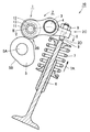
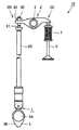
図1は、本発明の一実施の形態である実施の形態1における軌道部材を含むカムフォロアを備えた動弁装置の構成を示す概略図である。また、図2は、図1の線分II−IIに沿う概略断面図である。また、図3は、図2のカムフォロア付近を拡大して示した概略部分断面図である。図1〜図3を参照して、実施の形態1における軌道部材を含むカムフォロアを備えた動弁装置について説明する。
(Embodiment 1)
FIG. 1 is a schematic diagram illustrating a configuration of a valve operating apparatus including a cam follower including a track member according to the first embodiment which is an embodiment of the present invention. FIG. 2 is a schematic sectional view taken along line II-II in FIG. FIG. 3 is an enlarged schematic partial cross-sectional view showing the vicinity of the cam follower in FIG. With reference to FIGS. 1-3, the valve gear provided with the cam follower containing the track member in
図1および図2を参照して、動弁装置10は、総ころタイプのラジアルころ軸受であるカムフォロア1と、カムフォロア1を一方の端部2Bにおいて保持する保持部材としてのロッカーアーム2と、カムフォロア1の外輪としてのローラ11の外周面に、外周面5Bにおいて接触するように配置されたカム5と、ロッカーアーム2の他方の端部2Cに形成された貫通穴2Dに挿入され、ロックナット8によりロッカーアーム2に固定されたアジャストねじ9と、アジャストねじ9の一方の端部に、一方の端部において連結されたエンジンの給気または排気用の弁であるバルブ6とを備えている。
Referring to FIGS. 1 and 2, a
カムフォロア1は、外輪としての円環状のローラ11と、ローラ11を貫通する中空円筒状の軸12と、ローラ11および軸12の間に配置される複数のころ13を含んでいる。ロッカーアーム2は、中央部において軸受メタル4などを介してロッカーアーム軸3に保持されており、ロッカーアーム軸3を支点として回動自在となっている。バルブ6は、ばね7の弾性力により矢印7Aの向きに付勢されている。そのため、カムフォロア1はアジャストねじ9、ロッカーアーム2を介してばね7の弾性力により、常にカム5の外周面5Bに押し付けられている。カム5は、カムフォロア1の内輪である軸12の軸方向に垂直な断面において、卵形の断面形状を有している。そして、カム5はカムシャフト5Aと一体に形成されており、カムシャフト5Aを軸として回転可能に構成されている。
The
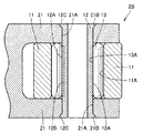
図2を参照して、ロッカーアーム2の一方の端部2B側は、1対の側壁21が形成された二股状の形状を有している。1対の側壁21のそれぞれには同軸の円柱状の貫通穴21Aが形成されている。そして、1対の側壁21の両方の貫通穴21Aを貫通するようにカムフォロア1の軸12が嵌め込まれている。軸12の外周面には軸転走面12Aが形成されており、軸転走面12Aに外周面であるころ転走面13Aにおいて接触するように、複数のころ13が配置されている。さらに、ローラ11は、1対の側壁21の間に配置され、かつローラ11の内周面には、軸転走面12Aに対向するようにローラ転走面11Aが形成されている。そして、ころ13は、ころ転走面13Aにおいて、ローラ転走面11Aと接触するように配置されている。これにより、ローラ11は軸12に対して回転自在に保持されている。
Referring to FIG. 2, one
さらに、図3を参照して、貫通穴21Aのそれぞれの外壁側開口付近には、軸12の軸方向に垂直な断面における直径が徐々に大きくなるテーパー部21Bが形成されている。そして、軸12の両端部は、300HV以下の硬度を有する低硬度領域12Cとなっており、塑性加工であるかしめ加工されることによりテーパー部21Bに沿うように変形されている。これにより、軌道部材としての軸12は、保持部材としてのロッカーアーム2に対して固定されている。一方、軸12の軸転走面12Aを含む環状の領域は、高周波焼入され、653HV以上の硬度を有する高硬度領域12Bとなっている。
Further, referring to FIG. 3, a tapered
なお、図1〜図3においては、軽量化のため中空状の軸12が採用された場合を示しているが、強度および剛性などを重視して中実の軸12を採用してもよい。
1 to 3 show a case where the
次に、実施の形態1における動弁装置10の動作について説明する。図1を参照して、カム5がカムシャフト5Aとともにカムシャフト5Aを軸として回転すると、カムシャフト5Aからカム5とカムフォロア1との接触部までの距離が周期的に変化する。そのため、ロッカーアーム2はロッカーアーム軸3を支点として揺動する。その結果、アジャストねじ9を介してバルブ6が往復運動する。これにより、エンジンの吸気弁または排気弁が開閉する。
Next, the operation of the
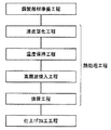
次に、実施の形態1における軌道部材としてのカムフォロア1の軸12および動弁装置10の製造方法について説明する。図4は、実施の形態1におけるカムフォロアの軸の製造方法の概略を示す図である。
Next, a method for manufacturing the
図4を参照して、実施の形態1におけるカムフォロアの軸の製造方法においては、まず鋼からなり、軌道部材としての軸12の概略形状に成形された部材である鋼製部材が準備される鋼製部材準備工程が実施される。具体的には、たとえばJIS規格SUJ2などの軸受鋼、SCM420などのクロムモリブデン鋼、SCr420などのクロム鋼などからなる鋼材が鍛造、切削等により加工されて、鋼製部材が作製される。
Referring to FIG. 4, in the method for manufacturing the cam follower shaft according to the first embodiment, a steel member is first prepared which is made of steel and is a member formed into a schematic shape of
次に、鋼製部材準備工程において準備された鋼製部材が熱処理される熱処理工程が実施される。熱処理工程は、浸炭窒化工程と、温度保持工程と、高周波焼入工程と、焼戻工程とを含んでいる。この熱処理工程の詳細については、後述する。 Next, a heat treatment step is performed in which the steel member prepared in the steel member preparation step is heat treated. The heat treatment process includes a carbonitriding process, a temperature holding process, an induction hardening process, and a tempering process. Details of this heat treatment step will be described later.
そして、熱処理工程において熱処理された鋼製部材が、仕上げ加工される仕上げ加工工程が実施される。具体的には、熱処理が完了した鋼製部材に対して研削加工、超仕上げ加工などの仕上げ加工が施されることにより、カムフォロア1の軸12が完成する。
And the finishing process in which the steel member heat-processed in the heat processing process is finished is implemented. Specifically, the
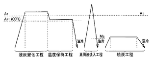
次に、実施の形態1におけるカムフォロアの軸の製造方法に含まれる熱処理工程の詳細について説明する。図5は、実施の形態1におけるカムフォロアの軸の製造方法に含まれる熱処理工程を示す図である。図5において、横方向は時間を示しており右に行くほど時間が経過していることを示している。また、図5において、縦方向は温度を示しており上に行くほど温度が高いことを示している。 Next, details of the heat treatment step included in the method for manufacturing the cam follower shaft in the first embodiment will be described. FIG. 5 is a diagram showing a heat treatment step included in the method for manufacturing the cam follower shaft in the first embodiment. In FIG. 5, the horizontal direction indicates time, and the time elapses toward the right. In FIG. 5, the vertical direction indicates the temperature, and the higher the temperature, the higher the temperature.
図5を参照して、熱処理工程においては、まず、鋼製部材が、A1点以上の温度である浸炭窒化温度に加熱されて浸炭窒化される浸炭窒化工程が実施される。具体的には、鋼製部材準備工程において準備された鋼製部材は、A1点以上の温度である800℃以上1000℃以下の温度、たとえば850℃に加熱され、60分間以上300分間以下の時間、たとえば150分間保持される。このとき、RXガスにアンモニア(NH3)を添加した雰囲気において加熱されることにより、鋼製部材の表層部の炭素濃度および窒素濃度が所望の濃度に調整される。 Referring to FIG. 5, in the heat treatment step, first, a carbonitriding step is performed in which the steel member is heated to a carbonitriding temperature that is a temperature equal to or higher than point A 1 and carbonitrided. Specifically, the steel member prepared in the steel member preparation step is heated to a temperature of 800 ° C. or higher and 1000 ° C. or lower, which is a temperature of one point or higher, for example, 850 ° C., and is 60 minutes or longer and 300 minutes or shorter. Hold for a time, eg 150 minutes. At this time, by heating in an atmosphere in which ammonia (NH 3 ) is added to RX gas, the carbon concentration and the nitrogen concentration in the surface layer portion of the steel member are adjusted to desired concentrations.
次に、浸炭窒化工程において浸炭窒化された鋼製部材が、浸炭窒化温度から、A1点よりも100℃低い温度以上A1点未満の温度域に冷却されて当該温度域に60分間以上180分間以下の時間保持される温度保持工程が実施される。 Then, the steel member is carbonitrided in the carbonitriding process, carburization from nitriding temperature, is cooled to a temperature range below 100 ° C. temperature lower than A 1 point than A 1 point or more for 60 minutes in the temperature range 180 A temperature holding step is performed in which the time is kept for a period of minutes or less.
このとき、鋼製部材を構成する鋼は、A1変態点未満の温度に冷却されることによりパーライト変態を開始する。パーライト変態は、時間が経過すれば、温度を下げなくても進行する。そのため上述のように60分間以上180分間以下の時間、上記温度域で保持されることにより、鋼製部材を構成する鋼の変態は、恒温変態の状態あるいは冷却速度が非常に小さい状態が確保されつつ、ほぼ完了する。その結果、当該鋼中の炭化物が十分に粗大化、凝集化して硬度が抑制される。 At this time, the steel forming the steel member starts pearlite transformation by being cooled to a temperature lower than the A 1 transformation point. The pearlite transformation proceeds over time without lowering the temperature. Therefore, as described above, by maintaining the temperature in the above temperature range for 60 minutes or more and 180 minutes or less, the transformation of the steel constituting the steel member is maintained in a constant temperature transformation state or a state where the cooling rate is very small. While almost complete. As a result, the carbides in the steel are sufficiently coarsened and agglomerated to suppress the hardness.
また、パーライト変態が進行する期間において、鋼製部材の温度が上記温度範囲に保持されるため、鋼製部材の形状、大きさ、同時に処理される鋼製部材の量などに関わらず、一定の状態に炭化物を粗大化、凝集化させることができる。さらに、鋼製部材の部位によって冷却速度が大きく異なることもないため、部位によらず、一定の状態に炭化物を粗大化、凝集化させることができる。その結果、軸12における低硬度領域12Cの硬度を安定して制御することが可能となり、割れを発生させることなく塑性加工することが可能な低硬度領域12Cを有する軸12を安定して製造することができる。また、浸炭窒化を実施した後、焼入を実施し、さらに高温焼戻を実施する従来の工程に比べて、熱処理工程を簡略化できるため、製造コストの上昇を抑制することができる。
In addition, since the temperature of the steel member is maintained in the above temperature range during the period when the pearlite transformation proceeds, the steel member has a constant temperature regardless of the shape and size of the steel member and the amount of the steel member processed at the same time. The carbide can be coarsened and agglomerated in the state. Furthermore, since the cooling rate does not vary greatly depending on the part of the steel member, the carbide can be coarsened and agglomerated in a constant state regardless of the part. As a result, the hardness of the
ここで、温度保持工程において、鋼製部材が保持されるべき温度は、炭化物の粗大化、凝集化を十分に進行させる観点から、具体的には、650℃以上720℃以下とされることが好ましい。また、より詳細には、鋼製部材が保持されることが好ましい温度は、鋼製部材を構成する鋼の種類によっても多少異なり、たとえばJIS SUJ2の場合650℃以上700℃以下、SCM420の場合670℃以上700℃以下であることが好ましい。さらに、温度保持工程において、鋼製部材が上述の温度域に保持される時間は、生産効率の向上とパーライト変態の十分な進行および冷却速度のばらつき抑制とを両立させる観点から、60分間以上120分間以下とされることが好ましい。 Here, in the temperature holding step, the temperature at which the steel member should be held may be specifically set to 650 ° C. or more and 720 ° C. or less from the viewpoint of sufficiently proceeding coarsening and agglomeration of carbides. preferable. More specifically, the temperature at which the steel member is preferably held is somewhat different depending on the type of steel constituting the steel member. For example, in the case of JIS SUJ2, 650 ° C. to 700 ° C., and in the case of SCM420, 670 It is preferable that it is 700 degreeC or more. Furthermore, in the temperature holding step, the time during which the steel member is held in the above-described temperature range is 60 minutes or longer from the viewpoint of achieving both improvement in production efficiency, sufficient progress of pearlite transformation, and suppression of variation in cooling rate. It is preferable that the time is not more than minutes.
次に、図5を参照して、温度保持工程が実施された鋼製部材は、取り扱いが容易な温度、たとえば室温まで冷却される。このとき、前述のように温度保持工程において、鋼製部材を構成する鋼のパーライト変態はほぼ完了しているため、冷却速度は鋼製部材の硬度にほとんど影響を与えない。したがって、生産効率を向上させるため、油冷、水冷などを実施して、鋼製部材を急冷することができる。 Next, referring to FIG. 5, the steel member that has been subjected to the temperature holding step is cooled to a temperature that is easy to handle, for example, room temperature. At this time, since the pearlite transformation of the steel constituting the steel member is almost completed in the temperature holding step as described above, the cooling rate hardly affects the hardness of the steel member. Therefore, in order to improve production efficiency, oil cooling, water cooling, etc. can be implemented and steel members can be rapidly cooled.
次に、鋼製部材において、軌道部材としての軸12の軸転走面12Aとなるべき領域を含む高硬度領域12B以外の領域である低硬度領域12C(両端部)が焼入硬化されることなく、高硬度領域12Bが高周波焼入される高周波焼入工程が実施される。具体的には、高硬度領域12Bの表面が誘導コイルに対向するように鋼製部材が高周波焼入装置にセットされ、当該誘導コイルに高周波電流が流されることにより高硬度領域12BがA1点以上の温度である800℃以上1000℃以下の温度、たとえば900℃に誘導加熱される。その後、A1点以上の温度域からMS点未満の温度まで、たとえば油冷または水冷されることにより急冷される。これにより、低硬度領域12Cが焼入硬化されることなく、高硬度領域12Bが焼入硬化される。ここで、高硬度領域12Bを含む鋼製部材の表層部は浸炭窒化工程において浸炭窒化されている。そのため、高周波焼入工程において高硬度領域12Bが高周波焼入れされることにより、軸転走面12Aは転動疲労に対する抵抗性の高い領域となり、軸12に優れた転動疲労寿命特性を付与することができる。
Next, in the steel member, the
また、軸転走面12A直下の表層部は、浸炭窒化された後、高周波焼入れされることにより、10体積%以上50体積%以下、あるいはより好ましい範囲である15体積%以上35体積%以下の残留オーステナイト量を含むとともに、オーステナイト結晶粒度が11番以上(旧オーステナイト結晶粒の粒度番号;JIS G 0551)の鋼組織とされる。そのため、軸12の転動疲労寿命特性は、一層向上する。なお、表層部とは、転走面からの距離が0.2mm以内の領域をいう。
Further, the surface layer portion immediately below the
ここで、高周波焼入工程における上記誘導加熱は、被処理物である軸12の内部に発生するうず電流によるジュール熱とヒステリシス損失による仕事量に相当する熱の発生により実現されるため、誘導コイルに流される高周波電流の周波数、電源の出力、加熱時間などを制御することにより、軸12のうち所望部分のみを局所的に加熱することができる。そのため、容易に、低硬度領域12Cを焼入硬化することなく、高硬度領域12Bを焼入硬化することができる。
Here, the induction heating in the induction hardening process is realized by the generation of heat corresponding to the work due to the Joule heat generated by the eddy current and the hysteresis loss generated in the
次に、図5を参照して、焼戻工程が実施される。具体的には、高周波焼入工程が実施された鋼製部材が、A1点未満の温度である150℃以上350℃以下の温度、たとえば180℃に加熱され、30分間以上240分間以下の時間、たとえば120分間保持されて、その後室温の空気中で冷却される(空冷)。以上の手順により、実施の形態1における軌道部材の製造工程に含まれる熱処理工程は完了する。 Next, referring to FIG. 5, a tempering step is performed. Specifically, the steel member subjected to the induction hardening process is heated to a temperature of 150 ° C. or higher and 350 ° C. or lower, which is a temperature below A 1 point, for example, 180 ° C., and a time of 30 minutes or longer and 240 minutes or shorter. For example, it is held for 120 minutes and then cooled in air at room temperature (air cooling). By the above procedure, the heat treatment process included in the manufacturing process of the raceway member in the first embodiment is completed.
上記実施の形態1における軌道部材としての軸12の製造方法によれば、製造コストの上昇を抑制しつつ、浸炭窒化された転走面12Aを含む高硬度領域12Bの硬度を十分に高くして、転走面12Aに優れた転動疲労寿命特性を付与するとともに、軸12の両端部である低硬度領域12Cの硬度を安定して制御して抑制することにより、軸12の両端部(低硬度領域12C)を割れの発生を回避しながら塑性変形可能とし、塑性変形による固定が容易な軸12を製造することができる。
According to the method of manufacturing the
そして、上記実施の形態1における軌道部材の製造方法により製造された本発明に実施の形態1における軌道部材としての軸12は、製造コストの上昇が抑制されつつ、転走面を含む領域の硬度が高く、十分な転動疲労寿命を確保されているとともに、塑性変形する領域の硬度が安定して制御された軌道部材となっている。
The
ここで、A1点とは鋼を加熱した場合に、鋼の組織がフェライトからオーステナイトに変態を開始する温度に相当する点をいう。また、MS点とはオーステナイト化した鋼が冷却される際に、マルテンサイト化を開始する温度に相当する点をいう。 Here, the point A 1 in the case of heating the steel refers to a point that the structure of the steel corresponds to the temperature to start the transformation from ferrite to austenite. Further, the M S point when the steel was austenitized is cooled, it refers to a point corresponding to a temperature to initiate the martensite.
次に、実施の形態1における動弁装置10の製造方法について説明する。図6は、実施の形態1における動弁装置10の製造方法の概略を示す図である。
Next, the manufacturing method of the
図1および図6を参照して、実施の形態1における動弁装置10の製造方法は、カムフォロア1と、カムフォロア1を保持する保持部材としてのロッカーアーム2とを有し、エンジン(図示しない)の給気弁または排気弁であるバルブ6を動作させる動弁装置の製造方法である。当該動弁装置10の製造方法は、カムフォロア1を製造するカムフォロア製造工程と、保持部材としてのロッカーアーム2を製造する保持部材製造工程と、カムフォロア1を、保持部材としてのロッカーアーム2に取り付ける取り付け工程と、カムフォロアが取り付けられたロッカーアーム2と、別途準備されたカム5、バルブ6、ばね7などとを組み合わせて動弁装置10を組立てる組立て工程とを備えている。
Referring to FIGS. 1 and 6, the method for manufacturing
ここで、カムフォロア製造工程においては、カムフォロア1を構成する軌道部材としての軸12が、上述の実施の形態1における軌道部材の製造方法により製造される。
Here, in the cam follower manufacturing process, the
また、取り付け工程においては、図3を参照して、軸12の両端部である低硬度領域12Cが塑性加工されることにより、軸12がロッカーアーム2に対して固定されて、カムフォロア1がロッカーアーム2に取り付けられる。より詳細に説明すると、ローラ11とローラ11のローラ転走面11Aに接触するように配置された複数のころ13がロッカーアーム2の一方の端部2B側に形成された1対の側壁21の間に挿入される。その後、1対の側壁21のそれぞれに形成された貫通穴21Aを同時に貫通し、かつ軸転走面12Aが複数のころ13に接触するように、軸12が挿入される。そして、軸12の両端部である低硬度領域12Cが塑性加工であるかしめ加工されることにより、軸12がロッカーアーム2に対して固定され、カムフォロア1がロッカーアーム2に取り付けられる。
Further, in the attaching process, referring to FIG. 3, the
実施の形態1における動弁装置10の製造方法においては、軸12が、上述の実施の形態1における軌道部材の製造方法により製造され、当該軸12がかしめ加工されることにより軸12がロッカーアーム2に対して固定され、カムフォロア1がロッカーアーム2に取り付けられる。そのため、実施の形態1における動弁装置10の製造方法によれは、製造コストの上昇を抑制しつつ、軌道部材としての軸12が十分な転動疲労寿命を有していることにより十分な耐久性を有しているとともに、塑性変形を利用したカムフォロアの取り付けを容易に実施することができる動弁装置10の製造方法を提供することができる。
In the manufacturing method of the
(実施の形態2)
図7は、本発明の一実施の形態である実施の形態2における軌道部材を含むカムフォロアを備えた動弁装置の構成を示す概略図である。図7を参照して、実施の形態2における軌道部材を含むカムフォロアを備えた動弁装置およびその製造方法について説明する。
(Embodiment 2)
FIG. 7 is a schematic diagram showing a configuration of a valve gear including a cam follower including a track member according to the second embodiment which is an embodiment of the present invention. With reference to FIG. 7, the valve operating apparatus provided with the cam follower containing the track member in
図7を参照して、実施の形態2における動弁装置10は、上述の実施の形態1における動弁装置10と基本的には同様の構成を有している。しかし、実施の形態2における動弁装置10は、ロッカーアーム2の回動の支点がロッカーアーム2の一方の端部2Bとなる点において、実施の形態1の動弁装置10とは異なっている。
Referring to FIG. 7,
すなわち、実施の形態2における動弁装置10においては、ロッカーアーム2の一方の端部2B側に図示しないピボットが当接するピボット当接部22が形成されている。そして、ロッカーアーム2は、ピボット当接部22を支点として回動自在に保持されている。
That is, in the
カム5がカムシャフト5Aとともにカムシャフト5Aを軸として回転すると、カムシャフト5Aからカム5とカムフォロア1との接触部までの距離が周期的に変化する。そのため、ロッカーアーム2はピボット当接部22を支点として揺動する。その結果、バルブ6が往復運動して、エンジンの吸気弁または排気弁が開閉する。
When the
なお、実施の形態2における軌道部材としての軸12および動弁装置10は、上述のように実施の形態1における軸12および動弁装置10と基本的には同様の構成を有しており、同様の製造方法により製造することができる。
The
(実施の形態3)
図8は、本発明の一実施の形態である実施の形態3における軌道部材を含むカムフォロアを備えた動弁装置の構成を示す概略図である。また、図9は、図8のカムフォロア周辺を拡大して示した概略図である。図8および図9を参照して、実施の形態3における軌道部材を含むカムフォロアを備えた動弁装置およびその製造方法について説明する。
(Embodiment 3)
FIG. 8 is a schematic view showing a configuration of a valve gear including a cam follower including a track member according to the third embodiment which is an embodiment of the present invention. FIG. 9 is an enlarged schematic view showing the periphery of the cam follower in FIG. With reference to FIG. 8 and FIG. 9, the valve operating apparatus provided with the cam follower containing the track member in
図8および図9を参照して、実施の形態3における動弁装置10は、上述の実施の形態1における動弁装置10と基本的には同様の構成を有している。しかし、実施の形態3における動弁装置10は、ロッカーアーム2に直接カムフォロア1が取り付けられるのではなく、ロッカーアーム2とカムフォロア1との間にプッシュロッド90が介在し、カムフォロア1がプッシュロッド90に取り付けられている点において、実施の形態1の動弁装置10とは異なっている。
Referring to FIGS. 8 and 9,
すなわち、ロッカーアーム2の一方の端部2Bには、ロックナット82によりロッカーアーム2に対して固定されたアジャストねじ80および連結部材81を介して、棒状の形状を有するプッシュロッド90が連結されている。保持部材としてのプッシュロッド90において、ロッカーアーム2と連結されている側とは反対側の端部には、カムフォロア1が取り付けられている。そして、カム5は、外周面5Bにおいてカムフォロア1のローラ11の外周面と接触するように配置されている。
That is, a
カム5がカムシャフト5Aとともにカムシャフト5Aを軸として回転すると、カムシャフト5Aからカム5とカムフォロア1との接触部までの距離が周期的に変化する。そのため、ロッカーアーム2はプッシュロッド90により一方の端部2Bが押されることにより、ロッカーアーム軸3を支点として揺動する。その結果、バルブ6が往復運動して、エンジンの吸気弁または排気弁が開閉する。
When the
なお、実施の形態3における軌道部材としての軸12および動弁装置10は、上述のように実施の形態1における軸12および動弁装置10と基本的には同様の構成を有しており、同様の製造方法により製造することができる。
In addition, the
以下、本発明の実施例1について説明する。本発明の軌道部材の製造方法により製造した軌道部材の特性を評価する試験を行なった。試験の手順は以下のとおりである。
まず、試験の対象となる試験片の作製方法について説明する。本発明の実施例として、素材として軸受鋼であるJIS SUJ2を採用し、図4および図5に基づいて説明した実施の形態1における軌道部材としての軸12の製造方法と同様の製造方法により、外径14.6mm、長さ17.3mmの中実円柱状の試験片(カムフォロアの軸)を作製した。熱処理工程においては、図5を参照して、A1点以上の温度である850℃に加熱して浸炭窒化した後(浸炭窒化工程)、A1点よりも100℃低い温度以上A1点未満の温度である650℃まで冷却し、120分間650℃に保持した(温度保持工程)。その後、油中に浸漬することにより冷却(油冷)した。さらに、転走面となるべき領域を含む領域を焼入硬化する高周波焼入を実施した後(高周波焼入工程)、180℃に加熱して120分間保持することにより焼戻を行ない(焼戻工程)、熱処理工程を終了した(実施例A、B)。
First, a method for producing a test piece to be tested will be described. As an example of the present invention, JIS SUJ2 which is a bearing steel is adopted as a raw material, and by a manufacturing method similar to the manufacturing method of the
一方、本発明の範囲外の比較例として、上記試験片と同様の工程において、熱処理工程の浸炭窒化工程および温度保持工程を省略し、高周波焼入工程および焼戻工程のみを行なった試験片も作製した(比較例A、B)。 On the other hand, as a comparative example outside the scope of the present invention, a test piece in which the carbonitriding process and the temperature holding process of the heat treatment process are omitted and only the induction hardening process and the tempering process are performed in the same process as the above test piece It produced (comparative example A, B).
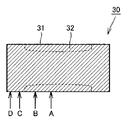
次に、特性評価の方法について説明する。上記試験片の外周面の硬度、転走面における残留オーステナイト量およびオーステナイト結晶粒度番号を調査した。図10は、試験片の硬度の測定位置を示す図である。図10を参照して、試験片としてのカムフォロアの軸30の外周面の硬度は、外周面の端部から長手方向にそれぞれ8.65mm、5.0mm、2.0mmおよび1.0mm離れた位置である測定位置A、B、CおよびDを、ビッカース硬度計により測定した。ここで、測定位置AおよびBは高硬度領域32の表面である転走面31に含まれる位置、測定位置CおよびDは転走面31以外の領域に含まれる位置である。
Next, a characteristic evaluation method will be described. The hardness of the outer peripheral surface of the test piece, the amount of retained austenite on the rolling surface, and the austenite grain size number were investigated. FIG. 10 is a diagram showing a measurement position of the hardness of the test piece. Referring to FIG. 10, the hardness of the outer peripheral surface of the
転走面31における残留オーステナイト量は、X線回折計(XRD)を用いて、当該部位のマルテンサイトα(211)面とオーステナイトγ(220)面との回折強度とを測定することにより、算出した。また、オーステナイト結晶粒度番号は、JIS G 0551に記載された旧オーステナイト結晶粒の粒度番号の測定方法により測定した。
The amount of retained austenite on the rolling

表1に、特性評価の結果を示す。表1を参照して、本発明の実施例の製造方法により作製された実施例Aおよび実施例Bは、転走面31に含まれる測定位置AおよびBにおける硬度が790〜805HVとなっており、転動疲労寿命の向上が期待できる硬度となっている。また、転走面31以外の領域である測定位置CおよびDにおける硬度は、220〜235HVとなっており、かしめ加工などの塑性加工を、割れを発生させることなく実施できる硬度範囲である300HV以下となっている。
Table 1 shows the results of the characteristic evaluation. Referring to Table 1, in Example A and Example B produced by the manufacturing method of the example of the present invention, the hardness at measurement positions A and B included in the rolling
一方、本発明の範囲外である従来の製造方法により作製された比較例AおよびBは、転走面31に含まれる測定位置AおよびBにおける硬度が735〜780HVとなっている。実施例AおよびBに比べて硬度が低くなっているのは、比較例AおよびBの試験片が浸炭窒化されていないことに起因していると考えられる。また、転走面31以外の領域である測定位置CおよびDにおける硬度は、200〜220HVとなっている。
On the other hand, Comparative Examples A and B produced by a conventional manufacturing method that is outside the scope of the present invention have hardnesses of 735 to 780 HV at measurement positions A and B included in the rolling
また、実施例Aおよび実施例Bは、転走面31における残留オーステナイト量が31.5〜32.5体積%となっている。これは、転動疲労寿命、特に硬質の異物が潤滑剤に混入する異物混入環境等における転動疲労寿命の向上と、寸法安定性とを両立するために好ましい範囲である10体積%以上50体積%以下、特に好ましい範囲である15体積%以上35体積%以下に含まれる。
In Examples A and B, the amount of retained austenite on the rolling
一方、比較例Aおよび比較例Bは、転走面31における残留オーステナイト量が7.5〜8.5体積%となっている。実施例AおよびBに比べて残留オーステナイト量が少なくなっているのは、比較例AおよびBの試験片が浸炭窒化されていないことに起因していると考えられる。その結果、比較例AおよびBの残留オーステナイト量は、転動疲労寿命、特に異物混入環境等における転動疲労寿命の向上と、寸法安定性とを両立するために好ましい範囲である10体積%以上50体積%以下の範囲外となっている。
On the other hand, in Comparative Example A and Comparative Example B, the amount of retained austenite on the rolling
また、実施例Aおよび実施例Bは、転走面31におけるオーステナイト結晶粒の粒度番号が12となっており、転動疲労寿命、靭性等を向上させるために好ましい範囲である11以上となっている。
In Examples A and B, the austenite grain size number in the rolling
一方、比較例Aおよび比較例Bは、転走面31におけるオーステナイト結晶粒の粒度番号が10.5〜11となっている。実施例AおよびBに比べて粒度番号が小さく(旧オーステナイト結晶粒が大きく)なっているのは、比較例AおよびBの試験片が浸炭窒化されていないため、高周波焼入の際にオーステナイト結晶粒の生成サイトとなる炭化物の数密度が実施例AおよびBに比べて少なくなっていることに起因していると考えられる。
On the other hand, in Comparative Example A and Comparative Example B, the austenite crystal grain size numbers in the rolling
以上より、本発明の軌道部材の製造方法により作製された軌道部材は、従来の軌道部材に比べて転走面の硬度およびオーステナイト結晶粒度番号が大きく、残留オーステナイト量が好ましい範囲となっているとともに、塑性加工が容易な領域が形成されている。そのため、本発明の軌道部材の製造方法により作製された軌道部材は、転走面の転動疲労寿命が優れているとともに、かしめ加工などの塑性加工を利用した軌道部材の固定が容易となっていることが確認された。 As described above, the race member produced by the method for producing a race member according to the present invention has a rolling surface hardness and austenite grain size number larger than those of conventional race members, and the amount of retained austenite is in a preferred range. A region where plastic processing is easy is formed. Therefore, the race member produced by the method for producing a race member of the present invention has an excellent rolling fatigue life of the raceway surface, and it becomes easy to fix the race member using plastic working such as caulking. It was confirmed that
以下、本発明の実施例2について説明する。本発明の軌道部材の製造方法により製造した軌道部材の転動疲労寿命を調査する試験を行なった。試験の手順は以下のとおりである。
上述の実施例1において作製された図10に示す試験片であるカムフォロアの軸を内輪として、外輪回転型転動疲労寿命試験を実施した。図11は、実施例2の試験に用いられた転動疲労寿命試験機の主要部を示す概略図である。図11を参照して、実施例2の転動疲労寿命試験の試験方法について説明する。 The outer ring rotation type rolling fatigue life test was conducted using the cam follower shaft, which is the test piece shown in FIG. FIG. 11 is a schematic view showing a main part of a rolling fatigue life tester used in the test of Example 2. With reference to FIG. 11, the test method of the rolling fatigue life test of Example 2 will be described.
図11を参照して、転動疲労寿命試験機40は、図示しない動力源に接続された回転軸41と、中心を含む領域を回転軸41が貫通し、回転軸41と一体に回転可能に構成された円盤状の駆動ローラ42と、回転軸41を軸周りに回転自在に支持する1対の軸受45とを備えている。
Referring to FIG. 11, the rolling
そして、駆動ローラの外周面42Aに対して外周面において接触するように円環状の外輪43が配置され、外輪43の内周面に対して外周面において接触するように複数のころ44が配置される。さらに、図10および図11を参照して、外輪43を貫通し、転走面31においてころ44に接触するように、試験片としてのカムフォロアの軸30が固定されて配置される。
An annular
図示しない動力源により回転軸41が軸周りに回転すると、回転軸41と一体に駆動ローラ42が回転する。そして、駆動ローラ42により駆動されて、外輪43が回転する。その結果、固定されたカムフォロアの軸30の転走面31をころ44が転走する。ここで、カムフォロアの軸30に負荷される荷重は2200N、外輪43の回転速度は7000回転/分、潤滑油はエンジンオイル(SAE粘度規格:10W−30)、油温は100℃の条件の下で、試験を実施した。この条件によれば、試験中に表面損傷または内部起点剥離のいずれかが発生する。したがって、本試験により、表面損傷および内部起点剥離の両方の寿命を確認することができる。そして、カムフォロアの軸30に剥離が発生するまでの時間(転動疲労寿命)を調査した。さらに、実験の結果得られた転動疲労寿命を統計的に解析し、10%の試験片が剥離するまでの時間(L10寿命)を算出した。表2に試験結果を示す。
When the
表2においては、比較例AのL10寿命を1とした場合の、各試験片の寿命比が示されている。表2を参照して、本発明の実施例である実施例AおよびBのカムフォロアの軸は、従来のカムフォロアの軸である比較例AおよびBに対して3倍程度の転動疲労寿命を有している。これは、実施例AおよびBにおいては、浸炭窒化処理が実施されることにより、前述のように、オーステナイト結晶粒度が小さく、かつ残留オーステナイト量が好ましい範囲とされていることに起因していると考えられる。 In Table 2, the life ratio of each test piece when the L10 life of Comparative Example A is set to 1 is shown. Referring to Table 2, the cam follower shafts of Examples A and B, which are embodiments of the present invention, have a rolling fatigue life of about three times that of Comparative Examples A and B, which are conventional cam follower shafts. is doing. In Examples A and B, when carbonitriding is performed, the austenite grain size is small and the amount of retained austenite is within a preferable range as described above. Conceivable.
以上の実施例1および2の結果より、本発明の軌道部材の製造方法によれば、熱処理工程の工程数を増加させないことにより製造コストの上昇を抑制しつつ、浸炭窒化および高周波焼入により転走面を含む領域を硬度が十分に高く、かつ転動疲労に対する抵抗の大きい材質にするとともに、転走面以外の領域の硬度を安定して制御して抑制し、当該領域の塑性変形を利用した軌道部材の固定が容易な軌道部材を製造することができることが確認された。 From the results of Examples 1 and 2 above, according to the raceway member manufacturing method of the present invention, the increase in the manufacturing cost is suppressed by not increasing the number of steps of the heat treatment step, and carbon nitrided and induction hardening are used. The area including the running surface is made of a material with sufficiently high hardness and high resistance to rolling fatigue, and the hardness of the area other than the rolling surface is stably controlled and suppressed, and plastic deformation in the area is used. It was confirmed that a track member that can be easily fixed can be manufactured.
今回開示された実施の形態および実施例はすべての点で例示であって、制限的なものではないと考えられるべきである。本発明の範囲は上記した説明ではなくて特許請求の範囲によって示され、特許請求の範囲と均等の意味、および範囲内でのすべての変更が含まれることが意図される。 The embodiments and examples disclosed herein are illustrative in all respects and should not be construed as being restrictive. The scope of the present invention is defined by the terms of the claims, rather than the description above, and is intended to include any modifications within the scope and meaning equivalent to the terms of the claims.
本発明の軌道部材および軌道部材の製造方法は、その一部が塑性変形することにより隣接する部材に対して固定される軌道部材およびその製造方法に、特に有利に適用され得る。また、本発明の動弁装置の製造方法は、その一部が塑性変形することにより隣接する部材に対して固定される軌道部材を有するカムフォロアを備えた動弁装置の製造方法に、特に有利に適用され得る。 The track member and the track member manufacturing method of the present invention can be applied particularly advantageously to a track member fixed to an adjacent member by plastic deformation of a part of the track member and the method of manufacturing the track member. In addition, the method for manufacturing a valve operating apparatus according to the present invention is particularly advantageous for a method for manufacturing a valve operating apparatus including a cam follower having a track member that is fixed to an adjacent member by plastic deformation of a part thereof. Can be applied.
1 カムフォロア、2 ロッカーアーム、2B 一方の端部、2C 他方の端部、2D 貫通穴、3 ロッカーアーム軸、4 軸受メタル、5 カム、5A カムシャフト、5B 外周面、6 バルブ、7 ばね、8 ロックナット、9 アジャストねじ、10 動弁装置、11 ローラ、11A ローラ転走面、12 軸、12A 軸転走面、12B 高硬度領域、12C 低硬度領域、13 ころ、13A ころ転走面、21 側壁、21A 貫通穴、21B テーパー部、22 ピボット当接部、30 カムフォロアの軸、31 転走面、32 高硬度領域、40 転動疲労寿命試験機、41 回転軸、42 駆動ローラ、42A 外周面、43 外輪、44 ころ、45 軸受、80 アジャストねじ、81 連結部材、82 ロックナット、90 プッシュロッド。 1 cam follower, 2 rocker arm, 2B one end, 2C other end, 2D through hole, 3 rocker arm shaft, 4 bearing metal, 5 cam, 5A camshaft, 5B outer peripheral surface, 6 valve, 7 spring, 8 Lock nut, 9 adjustment screw, 10 valve gear, 11 roller, 11A roller rolling surface, 12 shafts, 12A shaft rolling surface, 12B high hardness region, 12C low hardness region, 13 rollers, 13A roller rolling surface, 21 Side wall, 21A through hole, 21B taper part, 22 pivot contact part, 30 cam follower shaft, 31 rolling surface, 32 high hardness region, 40 rolling fatigue life tester, 41 rotating shaft, 42 driving roller, 42A outer peripheral surface , 43 Outer ring, 44 Roller, 45 Bearing, 80 Adjustment screw, 81 Connecting member, 82 Lock nut, 90 Push lock De.
Claims (3)
前記鋼製部材が熱処理される熱処理工程と、
前記熱処理工程において熱処理された前記鋼製部材が、仕上げ加工される仕上げ加工工程とを備え、
前記熱処理工程は、
前記鋼製部材が、A1点以上の温度である浸炭窒化温度に加熱されて浸炭窒化される浸炭窒化工程と、
前記浸炭窒化工程において浸炭窒化された前記鋼製部材が、前記浸炭窒化温度から、A1点よりも100℃低い温度以上A1点未満の温度域に冷却されて前記温度域に60分間以上180分間以下の時間保持される温度保持工程と、
前記温度保持工程よりも後で、前記鋼製部材において、前記軌道部材の転走面となるべき領域を含む高硬度領域以外の領域である低硬度領域が焼入硬化されることなく、前記高硬度領域が高周波焼入される高周波焼入工程とを含む、軌道部材の製造方法。 A steel member preparation step in which a steel member, which is a member made of steel and formed into a schematic shape of a raceway member, is prepared,
A heat treatment step in which the steel member is heat treated;
The steel member that has been heat-treated in the heat treatment step includes a finishing process for finishing.
The heat treatment step includes
A carbonitriding step in which the steel member is heated to a carbonitriding temperature which is a temperature of one point A or more and carbonitrided;
Wherein said steel member is carbonitrided in the carbonitriding process, the carburization from nitriding temperature, is cooled to a temperature range below 100 ° C. temperature lower than A 1 point than A 1 point or more for 60 minutes in the temperature range 180 A temperature holding step that is held for a period of minutes or less;
After the temperature holding step, in the steel member, the low hardness region which is a region other than the high hardness region including the region to be the rolling surface of the raceway member is not hardened and hardened. A method of manufacturing a raceway member, including an induction hardening process in which a hardness region is induction hardened.
前記カムフォロアを製造するカムフォロア製造工程と、
前記保持部材を製造する保持部材製造工程と、
前記カムフォロアを、前記保持部材に取り付ける取り付け工程とを備え、
前記カムフォロア製造工程においては、前記カムフォロアを構成する軌道部材が、請求項1に記載の軌道部材の製造方法により製造され、
前記取り付け工程においては、前記低硬度領域が塑性加工されることにより、前記軌道部材が前記保持部材に対して固定されて、前記カムフォロアが前記保持部材に取り付けられる、動弁装置の製造方法。 A method for manufacturing a valve operating device having a cam follower and a holding member for holding the cam follower, and operating at least one of an intake valve and an exhaust valve of an engine,
A cam follower manufacturing process for manufacturing the cam follower;
A holding member manufacturing process for manufacturing the holding member;
An attachment step of attaching the cam follower to the holding member;
In the cam follower manufacturing process, the track member constituting the cam follower is manufactured by the track member manufacturing method according to claim 1,
In the attachment step, the low hardness region is plastically processed, whereby the track member is fixed to the holding member, and the cam follower is attached to the holding member.
A track member manufactured by the method for manufacturing a track member according to claim 1.
Priority Applications (4)
| Application Number | Priority Date | Filing Date | Title |
|---|---|---|---|
| JP2006192994A JP2008020003A (en) | 2006-07-13 | 2006-07-13 | Process for producing track member and valve gear, and track member |
| CN2007800262017A CN101490431B (en) | 2006-07-13 | 2007-06-11 | Process for producing track member, process for producing valve gear, and track member |
| US12/373,379 US20090276992A1 (en) | 2006-07-13 | 2007-06-11 | Method for manufacturing raceway member, method for manufacturing valve train and raceway member |
| PCT/JP2007/061698 WO2008007509A1 (en) | 2006-07-13 | 2007-06-11 | Process for producing track member, process for producing valve gear, and track member |
Applications Claiming Priority (1)
| Application Number | Priority Date | Filing Date | Title |
|---|---|---|---|
| JP2006192994A JP2008020003A (en) | 2006-07-13 | 2006-07-13 | Process for producing track member and valve gear, and track member |
Publications (1)
| Publication Number | Publication Date |
|---|---|
| JP2008020003A true JP2008020003A (en) | 2008-01-31 |
Family
ID=38923075
Family Applications (1)
| Application Number | Title | Priority Date | Filing Date |
|---|---|---|---|
| JP2006192994A Pending JP2008020003A (en) | 2006-07-13 | 2006-07-13 | Process for producing track member and valve gear, and track member |
Country Status (4)
| Country | Link |
|---|---|
| US (1) | US20090276992A1 (en) |
| JP (1) | JP2008020003A (en) |
| CN (1) | CN101490431B (en) |
| WO (1) | WO2008007509A1 (en) |
Cited By (2)
| Publication number | Priority date | Publication date | Assignee | Title |
|---|---|---|---|---|
| WO2010037414A1 (en) * | 2008-09-30 | 2010-04-08 | Aktiebolaget Skf | Bearing heater |
| WO2023243332A1 (en) * | 2022-06-17 | 2023-12-21 | 日本トムソン株式会社 | Follower bearing, follower bearing module, and method of manufacturing inner member of follower bearing |
Families Citing this family (12)
| Publication number | Priority date | Publication date | Assignee | Title |
|---|---|---|---|---|
| WO2009054530A1 (en) * | 2007-10-24 | 2009-04-30 | Nippon Steel Corporation | Carbonitrided induction-hardened steel part with excellent rolling contact fatigue strength at high temperature and process for producing the same |
| US8109247B2 (en) * | 2008-05-19 | 2012-02-07 | GM Global Technology Operations LLC | Wear resistant camshaft and follower material |
| JP5898092B2 (en) * | 2010-12-13 | 2016-04-06 | 川崎重工業株式会社 | DRIVE CAM, MANUFACTURING METHOD THEREOF AND ENGINE VALVE DEVICE |
| JP2014503752A (en) | 2011-01-27 | 2014-02-13 | スクデリ グループ インコーポレイテッド | Lost motion variable valve actuation system with valve deactivation |
| WO2012103401A2 (en) * | 2011-01-27 | 2012-08-02 | Scuderi Group, Llc | Lost-motion variable valve actuation system with cam phaser |
| CN102219023B (en) * | 2011-04-21 | 2013-06-12 | 天津赛瑞机器设备有限公司 | Processing method of twisted guide rail |
| JP2015506436A (en) | 2012-01-06 | 2015-03-02 | スクデリ グループ インコーポレイテッド | Lost motion variable valve actuation system |
| EP2971636A1 (en) | 2013-03-15 | 2016-01-20 | Scuderi Group, Inc. | Split-cycle engines with direct injection |
| EP2971624B1 (en) | 2013-03-15 | 2018-03-14 | Roller Bearing Company of America, Inc. | Needle roller cam follower for higher mileage applications of light, medium and heavy duty vehicles |
| JP6433689B2 (en) * | 2014-06-12 | 2018-12-05 | Ntn株式会社 | Sliding constant velocity universal joint |
| CN104712383A (en) * | 2015-02-06 | 2015-06-17 | 上海尤顺汽车部件有限公司 | Rocker arm of improved engine valve mechanism and preparation method thereof |
| JP2017197829A (en) * | 2016-04-28 | 2017-11-02 | 株式会社ジェイテクト | Shaft member for rolling contact |
Citations (6)
| Publication number | Priority date | Publication date | Assignee | Title |
|---|---|---|---|---|
| JP2002194438A (en) * | 2000-12-22 | 2002-07-10 | Nsk Ltd | Rolling bearing |
| JP2004340221A (en) * | 2003-05-14 | 2004-12-02 | Nsk Ltd | Pinion shaft |
| JP2005299914A (en) * | 2003-06-05 | 2005-10-27 | Ntn Corp | Rolling bearing, cam follower with roller, and cam |
| JP2006002194A (en) * | 2004-06-16 | 2006-01-05 | Nsk Ltd | Method for manufacturing shaft |
| JP2006063915A (en) * | 2004-08-27 | 2006-03-09 | Ntn Corp | Rocker arm structure |
| JP4566036B2 (en) * | 2005-03-11 | 2010-10-20 | Ntn株式会社 | Rolling bearing |
Family Cites Families (3)
| Publication number | Priority date | Publication date | Assignee | Title |
|---|---|---|---|---|
| US7438477B2 (en) * | 2001-11-29 | 2008-10-21 | Ntn Corporation | Bearing part, heat treatment method thereof, and rolling bearing |
| JP3990254B2 (en) * | 2002-10-17 | 2007-10-10 | Ntn株式会社 | Full-roller type rolling bearing |
| JP2004293632A (en) * | 2003-03-26 | 2004-10-21 | Ntn Corp | Rolling bearing |
-
2006
- 2006-07-13 JP JP2006192994A patent/JP2008020003A/en active Pending
-
2007
- 2007-06-11 WO PCT/JP2007/061698 patent/WO2008007509A1/en active Application Filing
- 2007-06-11 US US12/373,379 patent/US20090276992A1/en not_active Abandoned
- 2007-06-11 CN CN2007800262017A patent/CN101490431B/en not_active Expired - Fee Related
Patent Citations (6)
| Publication number | Priority date | Publication date | Assignee | Title |
|---|---|---|---|---|
| JP2002194438A (en) * | 2000-12-22 | 2002-07-10 | Nsk Ltd | Rolling bearing |
| JP2004340221A (en) * | 2003-05-14 | 2004-12-02 | Nsk Ltd | Pinion shaft |
| JP2005299914A (en) * | 2003-06-05 | 2005-10-27 | Ntn Corp | Rolling bearing, cam follower with roller, and cam |
| JP2006002194A (en) * | 2004-06-16 | 2006-01-05 | Nsk Ltd | Method for manufacturing shaft |
| JP2006063915A (en) * | 2004-08-27 | 2006-03-09 | Ntn Corp | Rocker arm structure |
| JP4566036B2 (en) * | 2005-03-11 | 2010-10-20 | Ntn株式会社 | Rolling bearing |
Cited By (3)
| Publication number | Priority date | Publication date | Assignee | Title |
|---|---|---|---|---|
| WO2010037414A1 (en) * | 2008-09-30 | 2010-04-08 | Aktiebolaget Skf | Bearing heater |
| US9012819B2 (en) | 2008-09-30 | 2015-04-21 | Aktiebolaget Skf | Bearing heater |
| WO2023243332A1 (en) * | 2022-06-17 | 2023-12-21 | 日本トムソン株式会社 | Follower bearing, follower bearing module, and method of manufacturing inner member of follower bearing |
Also Published As
| Publication number | Publication date |
|---|---|
| CN101490431B (en) | 2011-01-05 |
| WO2008007509A1 (en) | 2008-01-17 |
| US20090276992A1 (en) | 2009-11-12 |
| CN101490431A (en) | 2009-07-22 |
Similar Documents
| Publication | Publication Date | Title |
|---|---|---|
| JP2008020003A (en) | Process for producing track member and valve gear, and track member | |
| EP2256307B1 (en) | Roller follower and valve train | |
| JP5611828B2 (en) | Rotating elements or rotating rings formed from bearing steel | |
| JP4486411B2 (en) | Cam follower with roller | |
| JP5895493B2 (en) | Rolling bearing manufacturing method, induction heat treatment apparatus | |
| JP5045491B2 (en) | Large rolling bearing | |
| US7377988B2 (en) | Positional fixing of a shaft | |
| JP2009052119A (en) | Heat-treatment method for steel, method for producing machine part, and machine part | |
| JP2008019482A (en) | Method for manufacturing orbital member, method for manufacturing dynamic valve, and orbital member | |
| JP2008063603A (en) | Method for manufacturing track member, method for manufacturing valve device, and track member | |
| JP2007182926A (en) | Manufacturing method for needle-like roll bearing raceway member, needle-like roll bearing raceway member, and needle-like roll bearing | |
| JP2007182609A (en) | Rolling member for use in wheel bearing device, manufacturing method therefor and wheel bearing device | |
| JP2007182607A (en) | Method for manufacturing rolling member for use in constant velocity joint, rolling member for use in constant velocity joint, and constant velocity joint | |
| JP2008064159A (en) | Method of manufacturing track member, method of manufacturing valve gear, and track member | |
| JP2009228829A (en) | Manufacturing method of stem, manufacturing method of bearing, stem, and bearing | |
| JP4228725B2 (en) | Method for manufacturing rolling and sliding parts and rolling bearing | |
| JP2010024492A (en) | Heat-treatment method for steel, method for manufacturing machine component, and machine component | |
| JP2007182603A (en) | Method for manufacturing rolling member, rolling member and rolling bearing | |
| JP5207236B2 (en) | Manufacturing method of shaft rod, manufacturing method of bearing, shaft rod and bearing | |
| JP4897060B2 (en) | Manufacturing method of roller shaft | |
| JP2006002194A (en) | Method for manufacturing shaft | |
| JP4134690B2 (en) | Hardening heat treatment method for cast iron member and hardened heat treated cast iron member | |
| JP2007327112A (en) | Machine member and rolling bearing | |
| JP4421334B2 (en) | bearing | |
| JP2006063917A (en) | Rolling bearing to be used for rocker arm |
Legal Events
| Date | Code | Title | Description |
|---|---|---|---|
| A621 | Written request for application examination |
Free format text: JAPANESE INTERMEDIATE CODE: A621 Effective date: 20090616 |
|
| A131 | Notification of reasons for refusal |
Free format text: JAPANESE INTERMEDIATE CODE: A131 Effective date: 20120522 |
|
| A02 | Decision of refusal |
Free format text: JAPANESE INTERMEDIATE CODE: A02 Effective date: 20120807 |