JP2008002090A - Housing building - Google Patents
Housing building Download PDFInfo
- Publication number
- JP2008002090A JP2008002090A JP2006170502A JP2006170502A JP2008002090A JP 2008002090 A JP2008002090 A JP 2008002090A JP 2006170502 A JP2006170502 A JP 2006170502A JP 2006170502 A JP2006170502 A JP 2006170502A JP 2008002090 A JP2008002090 A JP 2008002090A
- Authority
- JP
- Japan
- Prior art keywords
- floor
- space
- equipment
- residential building
- wall surface
- Prior art date
- Legal status (The legal status is an assumption and is not a legal conclusion. Google has not performed a legal analysis and makes no representation as to the accuracy of the status listed.)
- Pending
Links
Images


Abstract
Description
本発明は、住宅建物に関するものである。 The present invention relates to a residential building.
一般に、住宅建物内には、ガス、水道、空調、換気などの設備が設けられており、それらの設備配管などは、住宅建物内の居住空間の一部に設けたパイプスペースや、床下空間、天井裏空間などを介して住宅建物内に巡らされている。 In general, facilities such as gas, water, air conditioning, and ventilation are provided in residential buildings, and the equipment piping and the like are pipe space provided in a part of the living space in the residential building, underfloor space, It is circulated in the residential building through the space behind the ceiling.
従来より、これらの設備や配管は、それぞれが独立して設計されていた。すなわち、空調設備などは、各部屋毎に設けられている場合が多いので、各部屋毎に室内機を設置して室外機は、各部屋の外の外壁に固定したり、バルコニーに設けたりしていた。水道設備は、洗面、トイレ、風呂、キッチンなどをある程度近くに設けて配管が長くなるのを防止するとともに、給湯器は、これら設備の屋外の外壁に固定したり、バルコニーに設けたりしていた。 Conventionally, each of these facilities and piping has been designed independently. In other words, air conditioning equipment is often installed in each room, so an indoor unit is installed in each room, and the outdoor unit is fixed to the outer wall of each room or installed on the balcony. It was. The water supply facilities provided a washbasin, toilet, bath, kitchen, etc. close to some extent to prevent the pipes from becoming long, and the water heaters were fixed to the outdoor walls of these facilities or provided on the balcony .
また、換気設備については、例えば、上下フロア間の配管スペースを無くして各フロア毎に独立して設備および配管を設けることが提案されている(特許文献1参照)。
しかし、上記従来の換気設備の場合、配管スペースを無くすことができるものの、設備自体は住宅建物内の屋根裏や床下の狭小空間に設けられるので、設備の故障などを生じた場合には、これら屋根裏や床下の狭小空間で、メンテナンスを行わなければならないこととなる。 However, in the case of the conventional ventilation equipment described above, although the piping space can be eliminated, the equipment itself is provided in the attic in the residential building or in a narrow space under the floor. And maintenance in a small space under the floor.
また、上記従来の設備や配管は、水道、空調、換気などの設備毎にそれぞれが独立して設計されていたため、住宅建物のプランによっては、外壁のあらゆるところに給湯器や室外機が設けられ、外観が悪化することとなる。 In addition, since the conventional facilities and pipes are designed independently for each facility such as water supply, air conditioning, and ventilation, water heaters and outdoor units are installed everywhere on the outer wall depending on the plan of the residential building. The appearance will be deteriorated.
本発明は、係る実情に鑑みてなされたものであって、住宅建物の外観の向上を図るとともに、優れたメンテナンス性が得られ、住宅建物内部の空間設計の自由度を向上させることができる住宅建物を提供することを目的としている。 The present invention has been made in view of the actual situation, and it is possible to improve the appearance of a residential building, to obtain excellent maintainability, and to improve the freedom of space design inside the residential building. The purpose is to provide buildings.
上記課題を解決するための本発明の住宅建物は、住宅建物内の設備配管が、居住空間内の上下フロア間を通ることなく、住宅建物の一側壁面のみからそれぞれ屋外に取り出され、これらの配管は、この一側壁面の屋外に設置された住宅建物内の全ての設備装置とぞれぞれ接続されるとともに、これら配管および設備装置を被覆するように、住宅建物の一側壁面の屋外に被覆壁が設けられてなるものである。 In the residential building of the present invention for solving the above-mentioned problems, the facility piping in the residential building is taken out outdoors only from one side wall surface of the residential building without passing between the upper and lower floors in the living space. The piping is connected to all the equipment in the residential building installed on the outside of this one side wall, and the outside of the one side of the residential building is covered so as to cover these piping and equipment. Is provided with a covering wall.
また、設備配管は、床下空間および天井裏空間を介して住宅建物の一側壁面のみからそれぞれ屋外に取り出されてなるものである。 The facility piping is taken out from only one side wall surface of the residential building through the underfloor space and the ceiling back space.
以上述べたように、本発明によると、住宅建物の設備配管および設備装置を、住宅建物の一側壁面のみに設け、これら配管および設備装置を被覆するように、住宅建物の一側壁面に被覆壁を設けているので、住宅建物の外観からは、設備装置が一切見えないこととなり、住宅建物と被覆壁とが一体化した優れた外観が得られることとなる。 As described above, according to the present invention, the facility piping and equipment of the residential building are provided only on one side wall surface of the residential building, and the one side wall surface of the residential building is covered so as to cover these piping and equipment device. Since the wall is provided, the facility device cannot be seen at all from the appearance of the residential building, and an excellent appearance in which the residential building and the covering wall are integrated is obtained.
また、住宅建物の一側壁面に設備装置と配管とが集中しているので、メンテナンスが容易に行える。 Moreover, since the equipment and piping are concentrated on one side wall surface of the residential building, maintenance can be easily performed.
さらに、設備配管は、居住空間内の上下フロア間を通ることなく、床下空間および天井裏空間を介して、住宅建物の一側壁面のみからそれぞれ屋外に取り出しているので、居住空間は、パイプスペースを考慮する必要が無く、空間設計の自由度が向上することとなる。 Furthermore, since the facility piping is taken out from only one side wall surface of the residential building through the under floor space and the ceiling back space without passing between the upper and lower floors in the living space, the living space is the pipe space. Thus, the degree of freedom in space design is improved.
以下、本発明の実施の形態を図面を参照して説明する。 Hereinafter, embodiments of the present invention will be described with reference to the drawings.
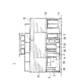
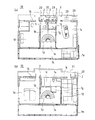
図1および図2は、住宅建物1の全体構成の概略を示し、図3は同住宅建物1の要部を示し、図4は同住宅建物1の間取りを示している。
1 and 2 show an outline of the overall configuration of the
すなわち、この住宅建物1は、住宅建物1内の設備配管2が、居住空間10内の上下フロア間を通ることなく、一階床下空間11、一階天井裏空間(二階床下空間)12および二階天井裏空間13を介して住宅建物1の一側壁面14のみからそれぞれ屋外に取り出され、これらの配管2は、この一側壁面14の屋外に設置された設備装置20とそれぞれ接続されるとともに、これら配管2および設備装置20を被覆するように、住宅建物の一側壁面14に被覆壁3、手摺り壁31が設けられいる。
That is, in this
住宅建物1は、玄関土間1aを入って奥行き方向Dに沿った全体が廊下1bを構成するようになされており、玄関土間1aの間口方向Wに隣接した位置にはキッチン1cが設けられている。キッチン1cから奥行きD方向に沿って順に、螺旋階段1dが設けられた階段室ホール1e、居間1fが設けられている。螺旋階段1dの間口方向Wに沿った背後には、家事室1g、納戸1hが設けられている。家事室1gから間口方向Wに沿って隣接した一側壁面14際の空間はトイレ1iとなされている。また、納戸1hから間口方向Wに沿って隣接した一側壁面14際の空間は住宅建物1内の電気関連の設備配線と電気関連の設備装置が設けられる機械室1jとなされている。
The
螺旋階段1dを上がった二階階段ホール1kから間口方向Wに隣接した一階の玄関土間1aと廊下1bとに相当する位置は、一階と同様に奥行き方向Dに沿った全体が廊下1mとなされている。一階の居間1fに相当する二階部分は寝室1nとなされており、一階のキッチン1cに相当する二階部分は和室1oとなされている。一階の納戸1hに相当する二階部分は書斎1pとなされている。一階の家事室1gに相当する二階部分は納戸1qとなされている。一階のトイレ1iおよび機械室1jに相当する二階部分は浴室1rおよび洗面所1sとなされている。和室1o、浴室1r、洗面所1s、寝室1nが隣接する一側壁面14に沿って、奥行き方向D全体にバルコニー1tが設けられている。
The position corresponding to the
設備配管2としては、住宅建物1内のガス管、上水道管、下水道管、給湯管、空調配管、換気配管などが挙げられる。設備装置20としては、給湯器または貯湯タンク、空調室外機、ガスメーターまたはプロパンガスボンベ、水道メーターなどが挙げられる。
Examples of the
各設備装置20は、一側壁面14の屋外で、バルコニー1tの下の空間に納まるように設置される。一部室外機はバルコニー1tに設置される。どこにどの設備装置20を設置するかは、一側壁面14から屋外へと取り出される各設備配管2の数や位置などを考慮して決定される。また、設備装置20によっては、一台だけ設けられ、一箇所からの分岐で各設備配管2に接続されて各部屋へと取り回されるものであってもよいし、各設備配管2に応じて複数台が設けられるものであってもよい。
Each
一階各部屋の設備配管2のうち、ガス管、上水道管、下水道管、給湯管は、それぞれ一階床下空間11から一側壁面14を介して屋外に取り出され、この屋外で一側壁面14に沿って各設備配管2を取り回してそれぞれの設備装置20と接続するようになされている。
Of the
一階各部屋の設備配管2のうち、空調配管、換気配管は、一階天井裏空間(二階床下空間)12から一側壁面14を介して屋外に取り出され、この屋外で、バルコニー1tの床下空間および一側壁面14に沿って各設備配管2を取り回してそれぞれの設備装置20と接続するようになされている。
Of the
二階各部屋の設備配管2のうち、ガス管、上水道管、下水道管、給湯管は、それぞれ二階天井裏空間(二階床下空間)12から一側壁面14を介して屋外に取り出され、この屋外で、バルコニー1tの床下空間および一側壁面13に沿って各設備配管2を取り回してそれぞれの設備装置20と接続するようになされている。
Of the
二階各部屋の設備配管2のうち、空調配管、換気配管は、二階天井裏空間13から一側壁面14を介して屋外に取り出され、それぞれの設備装置20と接続される。
Of the
ただし、空調装置(図示省略)が、天井噴出し型ではなく、一側壁面14の室内側に室内機(図示省略)を設けた壁取付型の場合、空調配管は、一階天井裏空間(二階床下空間)12や二階天井裏空間13からではなく、この室内機(図示省略)から直接一側壁面14を介して屋外に取り出される。
However, when the air conditioner (not shown) is not a ceiling ejection type but a wall-mounted type in which an indoor unit (not shown) is provided on the indoor side of the one
屋外に取り出された各設備配管2のうち、給湯管、空調配管などは、断熱被覆される。また、各設備配管2は、一側壁面14と近似する色のものを用いて意匠的に統一感を持たせてもよい。下水道管の場合、接続する設備装置20は無く、地中の下水本管や汚水マスへと接続されるが、一側壁面14を介して屋外に取り出してから取り回すことで、室内では、特に二階からの排水音を消して快適な居住環境を提供することができる。
Of each
被覆壁3は、アルミ製のルーバーを有する面材からなり、防犯と視線制御、通風を兼ね備えるようになされている。この被覆壁3は、二階バルコニー1tの手摺り壁31から連続して面一となるように設けられ、住宅建物1の外観からは、手摺り壁31および被覆壁3が住宅建物1と一体化して見えるようになされている。
The covering
このようにして構成される住宅建物1によると、設備配管2および設備装置20を、住宅建物1の一側壁面14のみに設け、これら設備配管2および設備装置20を被覆するように被覆壁3を設けているので、住宅建物1の外観からは、設備配管2や設備装置20が一切見えないこととなり、住宅建物1と被覆壁3と手摺り壁31とが一体化した優れた外観が得られることとなる。
According to the
また、住宅建物1の一側壁面14に全ての設備装置20と設備配管2とが集中しているので、メンテナンスが容易に行える。電気関連の設備配線および設備装置も、この一側壁面14から入って直ぐの機械室1kに集中させているので、住宅建物1の全ての設備管理を、この一側壁面14側から容易に行うことができる。
Moreover, since all the
さらに、全ての設備配管2は、居住空間内の上下フロア間を通ることなく、一側壁面14から直接、または、一階床下空間11、一階天井裏空間(二階床下空間)12および二階天井裏空間13を介して住宅建物1の一側壁面14のみからそれぞれ屋外に取り出しているので、居住空間10は、パイプスペースを考慮する必要が無く、空間設計の自由度が向上することとなる。
Further, all the
なお、本実施の形態において、設備装置20である空調室外機は、他の設備装置20と同様に、一側壁面14の屋外で、バルコニー1tの下の空間に納まるように設置しても良いが、本実施の形態の場合、バルコニー1tの手摺り壁31によって、被覆壁3と同様に、この空調室外機を隠すことができる。したがって、この空調室外機については、バルコニー1tに設けるようにしてもよい。特に、設備装置20が空調室外機の場合、一階天井裏空間(二階床下空間)12および二階天井裏空間13を介して住宅建物1の一側壁面14から取り出された設備配管2と接続されるので、一階の地面の高さに設けるより、出来るだけ高い位置に設けた方が効率的である。したがって、本実施の形態の場合には、バルコニー1tに設けるようにすることができるが、このバルコニー1tが存在しない場合には、被覆壁3で隠れる位置で、出来るだけ高い一側壁面14に空調室外機を固定することが好ましい。
In the present embodiment, the air conditioner outdoor unit that is the
また、一階床下空間11から一側壁面14を介して屋外に取り出される設備配管2のうち、下水道管のように直接地中の下水本管に導いた方が良い場合には、そのようにしてもよい。
Moreover, when it is better to directly lead to the underground sewage main pipe like the sewer pipe among the
設備配管のメンテナンス性に優れた住宅建物として利用できる。 It can be used as a residential building with excellent maintainability of equipment piping.
1 住宅建物
11 一階床下空間
12 一階天井裏空間(二階床下空間)
13 二階天井裏空間
14 一側壁面14
2 設備配管
20 設備装置
3 被覆壁
31 手摺り壁(被覆壁)
1
13 Second
2 Equipment piping 20
Claims (2)
Priority Applications (1)
| Application Number | Priority Date | Filing Date | Title |
|---|---|---|---|
| JP2006170502A JP2008002090A (en) | 2006-06-20 | 2006-06-20 | Housing building |
Applications Claiming Priority (1)
| Application Number | Priority Date | Filing Date | Title |
|---|---|---|---|
| JP2006170502A JP2008002090A (en) | 2006-06-20 | 2006-06-20 | Housing building |
Publications (1)
| Publication Number | Publication Date |
|---|---|
| JP2008002090A true JP2008002090A (en) | 2008-01-10 |
Family
ID=39006696
Family Applications (1)
| Application Number | Title | Priority Date | Filing Date |
|---|---|---|---|
| JP2006170502A Pending JP2008002090A (en) | 2006-06-20 | 2006-06-20 | Housing building |
Country Status (1)
| Country | Link |
|---|---|
| JP (1) | JP2008002090A (en) |
Cited By (2)
| Publication number | Priority date | Publication date | Assignee | Title |
|---|---|---|---|---|
| JP2012062736A (en) * | 2010-09-17 | 2012-03-29 | Toyota Home Kk | Exterior wall structure of building |
| JP2014084629A (en) * | 2012-10-23 | 2014-05-12 | Toyota Home Kk | Exterior wall structure of building |
Citations (1)
| Publication number | Priority date | Publication date | Assignee | Title |
|---|---|---|---|---|
| JPH04198559A (en) * | 1990-11-28 | 1992-07-17 | Misawa Homes Co Ltd | Equipment cover |
-
2006
- 2006-06-20 JP JP2006170502A patent/JP2008002090A/en active Pending
Patent Citations (1)
| Publication number | Priority date | Publication date | Assignee | Title |
|---|---|---|---|---|
| JPH04198559A (en) * | 1990-11-28 | 1992-07-17 | Misawa Homes Co Ltd | Equipment cover |
Cited By (2)
| Publication number | Priority date | Publication date | Assignee | Title |
|---|---|---|---|---|
| JP2012062736A (en) * | 2010-09-17 | 2012-03-29 | Toyota Home Kk | Exterior wall structure of building |
| JP2014084629A (en) * | 2012-10-23 | 2014-05-12 | Toyota Home Kk | Exterior wall structure of building |
Similar Documents
| Publication | Publication Date | Title |
|---|---|---|
| US20050188632A1 (en) | Modular core wall construction system | |
| ES2743102T3 (en) | System for buildings with a ventilation system and procedure for reconditioning an existing building in such a building | |
| JP2797245B2 (en) | Housing structure | |
| JP2008002090A (en) | Housing building | |
| JP2016216890A (en) | Apartment house | |
| EP3743570A1 (en) | A partially prefabricated building and method | |
| JPH08120955A (en) | Multiple dwelling house | |
| JP6018735B2 (en) | Housing drainage system | |
| KR20160122557A (en) | Duplex Structure for Apartment Buildings | |
| KR20190002855A (en) | Flat layout of residential buildings | |
| JP6956991B1 (en) | Underfloor structure of a multi-storey building | |
| JP7194568B2 (en) | collective housing building | |
| JPH09195537A (en) | Arrangement structure of habitable rooms and bathunit in living facilities | |
| JP2002021345A (en) | Multiple dwelling house | |
| JPH06128989A (en) | Installed piping structure of apartment house | |
| RU15486U1 (en) | RESIDENTIAL ROOM (OPTIONS), SEPARATE RESIDENTIAL PREMISES (OPTIONS), SEPARATE RESIDENTIAL PREMISES, SEPARATE APARTMENT (OPTIONS), RESIDENTIAL HOUSE SECTION (OPTIONS) | |
| Jarrar et al. | Design Of Mechanical System For The Public Services Center In Ramallah Municipality | |
| JPH1018370A (en) | Multiple dwelling house | |
| KR200437935Y1 (en) | Double air duct with noiseproof inter layer | |
| JP2015203547A (en) | Ventilation equipment of building | |
| Bohne | Building Services and Energy Efficient Buildings | |
| FI12408U1 (en) | Room unit | |
| JP2002235433A (en) | Tabular multiple dwelling house | |
| JP6506542B2 (en) | Variable structure of dwelling unit area of collective housing | |
| Wikström | HVAC solutions in standardised bathroom modules |
Legal Events
| Date | Code | Title | Description |
|---|---|---|---|
| A621 | Written request for application examination |
Effective date: 20080717 Free format text: JAPANESE INTERMEDIATE CODE: A621 |
|
| A977 | Report on retrieval |
Effective date: 20110325 Free format text: JAPANESE INTERMEDIATE CODE: A971007 |
|
| A131 | Notification of reasons for refusal |
Effective date: 20110426 Free format text: JAPANESE INTERMEDIATE CODE: A131 |
|
| A02 | Decision of refusal |
Free format text: JAPANESE INTERMEDIATE CODE: A02 Effective date: 20110913 |