JP2007532311A - Dynamic mixer and container combination - Google Patents
Dynamic mixer and container combination Download PDFInfo
- Publication number
- JP2007532311A JP2007532311A JP2007508817A JP2007508817A JP2007532311A JP 2007532311 A JP2007532311 A JP 2007532311A JP 2007508817 A JP2007508817 A JP 2007508817A JP 2007508817 A JP2007508817 A JP 2007508817A JP 2007532311 A JP2007532311 A JP 2007532311A
- Authority
- JP
- Japan
- Prior art keywords
- paste
- flow path
- container
- outlet
- mixing chamber
- Prior art date
- Legal status (The legal status is an assumption and is not a legal conclusion. Google has not performed a legal analysis and makes no representation as to the accuracy of the status listed.)
- Withdrawn
Links
Images


Classifications
-
- B—PERFORMING OPERATIONS; TRANSPORTING
- B05—SPRAYING OR ATOMISING IN GENERAL; APPLYING FLUENT MATERIALS TO SURFACES, IN GENERAL
- B05C—APPARATUS FOR APPLYING FLUENT MATERIALS TO SURFACES, IN GENERAL
- B05C17/00—Hand tools or apparatus using hand held tools, for applying liquids or other fluent materials to, for spreading applied liquids or other fluent materials on, or for partially removing applied liquids or other fluent materials from, surfaces
- B05C17/005—Hand tools or apparatus using hand held tools, for applying liquids or other fluent materials to, for spreading applied liquids or other fluent materials on, or for partially removing applied liquids or other fluent materials from, surfaces for discharging material from a reservoir or container located in or on the hand tool through an outlet orifice by pressure without using surface contacting members like pads or brushes
- B05C17/00503—Details of the outlet element
- B05C17/00516—Shape or geometry of the outlet orifice or the outlet element
-
- A—HUMAN NECESSITIES
- A61—MEDICAL OR VETERINARY SCIENCE; HYGIENE
- A61C—DENTISTRY; APPARATUS OR METHODS FOR ORAL OR DENTAL HYGIENE
- A61C5/00—Filling or capping teeth
- A61C5/60—Devices specially adapted for pressing or mixing capping or filling materials, e.g. amalgam presses
- A61C5/62—Applicators, e.g. syringes or guns
- A61C5/64—Applicators, e.g. syringes or guns for multi-component compositions
-
- A—HUMAN NECESSITIES
- A61—MEDICAL OR VETERINARY SCIENCE; HYGIENE
- A61C—DENTISTRY; APPARATUS OR METHODS FOR ORAL OR DENTAL HYGIENE
- A61C9/00—Impression cups, i.e. impression trays; Impression methods
- A61C9/0026—Syringes or guns for injecting impression material; Mixing impression material for immediate use
-
- B—PERFORMING OPERATIONS; TRANSPORTING
- B01—PHYSICAL OR CHEMICAL PROCESSES OR APPARATUS IN GENERAL
- B01F—MIXING, e.g. DISSOLVING, EMULSIFYING OR DISPERSING
- B01F27/00—Mixers with rotary stirring devices in fixed receptacles; Kneaders
- B01F27/05—Stirrers
- B01F27/09—Stirrers characterised by the mounting of the stirrers with respect to the receptacle
- B01F27/092—Stirrers characterised by the mounting of the stirrers with respect to the receptacle occupying substantially the whole interior space of the receptacle
-
- B—PERFORMING OPERATIONS; TRANSPORTING
- B01—PHYSICAL OR CHEMICAL PROCESSES OR APPARATUS IN GENERAL
- B01F—MIXING, e.g. DISSOLVING, EMULSIFYING OR DISPERSING
- B01F27/00—Mixers with rotary stirring devices in fixed receptacles; Kneaders
- B01F27/05—Stirrers
- B01F27/11—Stirrers characterised by the configuration of the stirrers
- B01F27/112—Stirrers characterised by the configuration of the stirrers with arms, paddles, vanes or blades
- B01F27/1121—Stirrers characterised by the configuration of the stirrers with arms, paddles, vanes or blades pin-shaped
-
- B—PERFORMING OPERATIONS; TRANSPORTING
- B01—PHYSICAL OR CHEMICAL PROCESSES OR APPARATUS IN GENERAL
- B01F—MIXING, e.g. DISSOLVING, EMULSIFYING OR DISPERSING
- B01F27/00—Mixers with rotary stirring devices in fixed receptacles; Kneaders
- B01F27/05—Stirrers
- B01F27/11—Stirrers characterised by the configuration of the stirrers
- B01F27/19—Stirrers with two or more mixing elements mounted in sequence on the same axis
- B01F27/191—Stirrers with two or more mixing elements mounted in sequence on the same axis with similar elements
-
- B—PERFORMING OPERATIONS; TRANSPORTING
- B05—SPRAYING OR ATOMISING IN GENERAL; APPLYING FLUENT MATERIALS TO SURFACES, IN GENERAL
- B05C—APPARATUS FOR APPLYING FLUENT MATERIALS TO SURFACES, IN GENERAL
- B05C17/00—Hand tools or apparatus using hand held tools, for applying liquids or other fluent materials to, for spreading applied liquids or other fluent materials on, or for partially removing applied liquids or other fluent materials from, surfaces
- B05C17/005—Hand tools or apparatus using hand held tools, for applying liquids or other fluent materials to, for spreading applied liquids or other fluent materials on, or for partially removing applied liquids or other fluent materials from, surfaces for discharging material from a reservoir or container located in or on the hand tool through an outlet orifice by pressure without using surface contacting members like pads or brushes
- B05C17/00553—Hand tools or apparatus using hand held tools, for applying liquids or other fluent materials to, for spreading applied liquids or other fluent materials on, or for partially removing applied liquids or other fluent materials from, surfaces for discharging material from a reservoir or container located in or on the hand tool through an outlet orifice by pressure without using surface contacting members like pads or brushes with means allowing the stock of material to consist of at least two different components
- B05C17/00566—Hand tools or apparatus using hand held tools, for applying liquids or other fluent materials to, for spreading applied liquids or other fluent materials on, or for partially removing applied liquids or other fluent materials from, surfaces for discharging material from a reservoir or container located in or on the hand tool through an outlet orifice by pressure without using surface contacting members like pads or brushes with means allowing the stock of material to consist of at least two different components with a dynamic mixer in the nozzle
Abstract
本発明は、ダイナミックミキサ(10)と、第1ペーストを収容する第1容器(11)と、第1ペーストと混合される第2ペーストを収容する第2容器(12)と、の組合せであって、ミキサ(10)が、混合チャンバ(20)と、混合ロータ(25)と、第1ペーストのための入口開口(21)と、第2ペーストのための入口開口(22)と、第1ペーストのための入口開口(21)から混合チャンバ(20)まで延在する第1流路と、第1ペーストのための入口開口(22)から混合チャンバ(20)まで延在する第2流路と、を備え、第1容器(11)が、第1ペーストのための出口開口(14)を備えた出口ソケット(13)と、出口ソケット(13)を通して出口開口(14)まで延在する第3流路と、を備え、出口ソケット(13)が、第1容器(11)から混合チャンバ(20)まで延在する第1全体流路を形成するようにミキサ(10)に接続され、第2容器(12)が、第2ペーストのための出口開口(16)を備えた出口ソケット(15)と、出口ソケット(15)を通して出口開口(16)まで延在する第4流路と、を備え、出口ソケット(15)が、第2容器(12)から混合チャンバ(20)まで延在する第2全体流路を形成するようにミキサ(10)に接続され、第1全体流路が、1.8mm2を上回る最小断面積(Aoc)を有し、第2全体流路が、第1全体流路の最小断面積(Aoc)より大きい最小断面積(Aob)を有する、組合せに関する。The present invention is a combination of a dynamic mixer (10), a first container (11) that contains a first paste, and a second container (12) that contains a second paste to be mixed with the first paste. The mixer (10) includes a mixing chamber (20), a mixing rotor (25), an inlet opening (21) for the first paste, an inlet opening (22) for the second paste, and a first A first flow path extending from the inlet opening (21) for the paste to the mixing chamber (20) and a second flow path extending from the inlet opening (22) for the first paste to the mixing chamber (20) A first container (11) having an outlet socket (13) with an outlet opening (14) for the first paste and extending through the outlet socket (13) to the outlet opening (14). 3 outlets, and an outlet socket (1 ) Is connected to the mixer (10) to form a first general flow path extending from the first container (11) to the mixing chamber (20), and the second container (12) is for the second paste An outlet socket (15) with an outlet opening (16) and a fourth flow path extending through the outlet socket (15) to the outlet opening (16), the outlet socket (15) being a second container A minimum cross-sectional area (Aoc) connected to the mixer (10) to form a second overall flow path extending from (12) to the mixing chamber (20), the first overall flow path being greater than 1.8 mm 2 And the second overall flow path has a minimum cross-sectional area (Aob) greater than the minimum cross-sectional area (Aoc) of the first overall flow path.
Description
本発明は、少なくとも2つのペーストを混合して、好ましくは歯科用物質を生成するダイナミックミキサに関する。本発明はまた、混合されるペーストのための容器に関する。さらに、本発明は、ダイナミックミキサと容器との組合せに関する。 The present invention relates to a dynamic mixer that mixes at least two pastes to produce a dental material, preferably. The invention also relates to a container for the paste to be mixed. Furthermore, the present invention relates to a combination of a dynamic mixer and a container.
特に、本発明は、たとえば歯科用印象材等の歯科用物質を、2つのペースト状成分、たとえば触媒ペーストおよび基剤ペーストから生成するために使用される、ダイナミックミキサと容器とに関する。 In particular, the present invention relates to a dynamic mixer and a container used to produce a dental substance, such as a dental impression material, from two pasty components, such as a catalyst paste and a base paste.
歯科用印象材等の歯科用物質を、2つのペースト状成分、たとえば触媒ペーストおよび基剤ペーストから生成するために使用されるダイナミックミキサおよび容器は、本技術分野において周知である。たとえば、以下の文献、すなわち(特許文献1)、(特許文献2)、(特許文献3)、(特許文献4)および(特許文献5)の各々は、歯科用印象材を触媒ペーストおよび基剤ペーストから生成するダイナミックミキサであって、混合チャンバと、混合チャンバ内の混合ロータと、触媒ペーストのための入口開口と、基剤ペーストのための入口開口と、触媒ペーストのための入口開口から混合チャンバまで延在する第1流路と、基剤ペーストのための入口開口から混合チャンバまで延在する第2流路と、を備えるダイナミックミキサについて開示している。 Dynamic mixers and containers used to produce dental materials, such as dental impression materials, from two pasty components, such as a catalyst paste and a base paste, are well known in the art. For example, each of the following documents, that is, (Patent Document 1), (Patent Document 2), (Patent Document 3), (Patent Document 4), and (Patent Document 5) is a dental impression material made of a catalyst paste and base A dynamic mixer that generates from a paste, mixing from a mixing chamber, a mixing rotor in the mixing chamber, an inlet opening for a catalyst paste, an inlet opening for a base paste, and an inlet opening for a catalyst paste A dynamic mixer is disclosed that includes a first flow path that extends to a chamber and a second flow path that extends from an inlet opening for a base paste to a mixing chamber.
(特許文献1)および(特許文献2)の各々はまた、混合されるペーストを収容する2つの容器であって、ダイナミックミキサと接続されるように設計され、第1容器が触媒ペーストを収容し第2容器が基剤ペーストを収容し、第1容器が触媒ペーストのための出口開口を有する出口ソケットを備え、第3流路が出口ソケットを通して出口開口まで延在し、第2容器が基剤ペーストのための出口開口を有する出口ソケットを備え、第4流路が出口ソケットを通して出口開口まで延在する、容器であり、第1容器がミキサに接続されると、第1全体流路が第1の容器から混合チャンバまで延在し、第2容器がミキサに接続されると、第2全体流路が第2容器から混合チャンバまで延在する、容器について開示している。 Each of (Patent Document 1) and (Patent Document 2) is also two containers containing pastes to be mixed, designed to be connected to a dynamic mixer, the first container containing a catalyst paste. The second container contains the base paste, the first container comprises an outlet socket having an outlet opening for the catalyst paste, the third flow path extends through the outlet socket to the outlet opening, and the second container is the base A container comprising an outlet socket having an outlet opening for paste, wherein the fourth flow path extends through the outlet socket to the outlet opening, and when the first container is connected to the mixer, the first overall flow path is Disclosed is a container that extends from one container to the mixing chamber, and when the second container is connected to the mixer, the second overall flow path extends from the second container to the mixing chamber.
コールテン/ウェイルデント(Coltene Whaledent)、デンツプライ(Dentsply)、GCおよびケテンバッハ(Kettenbach)といった会社は、各々、(特許文献1)の上述したダイナミックミキサに類似するダイナミックミキサ(以下、それぞれCWM1、DYM、GCMおよびKEM1として識別する)と、それに取り付けられそれぞれ触媒ペーストおよび基剤ペーストが充填される一対の第1容器および第2容器(以下、それぞれCWC1、DYC、GCCおよびKECとして識別する)と、を提案した。より詳細には、コールテン/ウェイルデント(Coltene Whaledent)は、それぞれ触媒容器および基剤容器(CWC1)に充填される印象材「プレジデント・システム360ヘヴィ・ボディ(President System 360 heavy body)を、この印象材を混合するかかるダイナミックミキサ(CWM1)とともに提案した。デンツプライ(Dentsply)は、各々触媒容器および基剤容器(DYC)に充填される印象材「アクアシル・モノフェーズ(Aquasil Monophase)FS DECA」および「アクアシル・ヘヴィ(Aquasil Heavy)FS DECA」を、これらの印象材を混合するかかるダイナミックミキサ(DYM)とともに提案した。GCは、各々がそれぞれの触媒容器および基剤容器(GCC)に充填される印象材「エクサジェット・ヘヴィ・ボディ・ノーマル・セット(Exajet Heavy Body Normal Set」および「エクサジェット・ヘヴィ・ボディ・ファスト・セット(Exajet Heavy Body Fast Set)」を、これらの印象材を混合するかかるダイナミックミキサ(GCM)とともに提案した。ケテンバッハ(Kettenbach)は、各々がそれぞれの触媒容器および基剤容器(KEC)に充填される「ケットシル(Kettosil)」、「モノプレン・トランスファ(Monopren Transfer)」、「パナシル・ビネティクス・パテ・ファスト(Panasil binetics putty fast)」、「パナシル・ビネティクス・パテ・ソフト(Panasil binetics putty soft)」、「パナシル・トレイ・ファスト(Panasil tray fast)」および「パナシル・トレイ・ソフト(Panasil tray soft)」を、これらの印象材を混合するかかるダイナミックミキサ(KEM1)とともに提案した。 Companies such as Colten Waledent, Dentsply, GC and Kettenbach are respectively dynamic mixers similar to the dynamic mixers described above (Patent Document 1) (hereinafter referred to as CWM1, DYM, GCM, respectively). And a pair of first and second containers (hereinafter identified as CWC1, DYC, GCC, and KEC, respectively) attached thereto and filled with catalyst paste and base paste, respectively. did. More specifically, Colten Waledent has added the impression material “Presidentent 360 heavy body” filled in the catalyst container and the base container (CWC1), respectively. Proposed together with such a dynamic mixer (CWM1) to mix the materials, Dentsply is the impression material “Aquasil Monophase FS DECA” and “Filled in catalyst and base containers (DYC), respectively. "Aquasil Heavy FS DECA" was proposed with such a dynamic mixer (DYM) to mix these impression materials. GC is an impression material “Exajet Heavy Body Normal Set” and “Exadget Heavy Body Fast” each filled in its respective catalyst container and base container (GCC). “Exajet Heavy Body Fast Set” was proposed with such a dynamic mixer (GCM) to mix these impression materials. Kettenbach each filled in its own catalyst container and base container (KEC) "Kettosil", "Monoprene Transfer", "Panasil binetics putty fa t) "," Panasil binetics putty soft "," Panasil tray fast "and" Panasil tray soft ", these impressions Proposed with such a dynamic mixer (KEM1) to mix the materials.
コールテン/ウェイルデント(Coltene Whaledent)およびケテンバッハ(Kettenbach)は、各々、(特許文献2)の上述したダイナミックミキサに類似するダイナミックミキサ(以下、それぞれCWM2およびKEM2として識別する)と、それに取り付けられかつそれぞれ触媒ペーストおよび基剤ペーストが充填される一対の第1容器および第2容器(以下、それぞれCWC2およびKECとして識別する)と、も提案した。より詳細には、コールテン/ウェイルデント(Coltene Whaledent)は、それぞれ触媒容器および基剤容器(CWC2)に充填される印象材「アフィニス・システム360モノ・ボディ(Affinis System 360 mono body)」および「アフィニス・システム360ヘヴィ・ボディ(Affinis System 360 heavy body)」を、これらの印象材を混合するかかるダイナミックミキサ(CWM2)とともに提案した。ケテンバッハ(Kettenbach)は、各々がそれぞれの触媒容器および基剤容器(KEC)に充填される上述した印象材「ケットシル(Kettosil)」、「モノプレン・トランスファ(Monopren Transfer)」、「パナシル・ビネティクス・パテ・ファスト(Panasil binetics putty fast)」、「パナシル・ビネティクス・パテ・ソフト(Panasil binetics putty soft)」、「パナシル・トレイ・ファスト(Panasil tray fast)」および「パナシル・トレイ・ソフト(Panasil tray soft)」を、これらの印象材を混合するかかるダイナミックミキサ(KEM2)とともに提案した。 Colten Waledent and Kettenbach are each a dynamic mixer (hereinafter identified as CWM2 and KEM2, respectively) similar to the dynamic mixer described above in (Patent Document 2), and attached to and respectively. A pair of first and second containers (hereinafter identified as CWC2 and KEC, respectively) filled with catalyst paste and base paste have also been proposed. More specifically, Colten Waledent is an impression material “Affinis System 360 mono body” and “Affinis” filled in a catalyst container and a base container (CWC2), respectively. A system 360 heavy body "was proposed along with such a dynamic mixer (CWM2) that mixes these impression materials. Kettenbach has the impression materials “Kettosil”, “Monoprene Transfer”, “Panacil Vinetics Putty” described above, each filled in a respective catalyst container and base container (KEC).・ “Panasil binetics putty fast”, “Panasil binetics putty soft”, “Panasil tray fast” and “Panasil tray fast (Pasyl tray fat)” Was proposed along with such a dynamic mixer (KEM2) to mix these impression materials.
カニエデンタ(Kaniedenta)といった会社は、(特許文献3)の上述したダイナミックミキサに類似するダイナミックミキサ(以下KAMとして識別する)と、そこに取り付けられかつそれぞれ触媒ペーストおよび基剤ペーストが充填される一対の第1容器および第2容器(以下KACとして識別する)と、を提案した。より詳細には、カニエデンタ(Kaniedenta)は、各々がそれぞれの触媒容器および基剤容器(KAC)に充填される印象材「シンメトリック・コンフォート(Symmetric Comfort)」、「シンメトリック・クイック・コンフォート(Symmetric Quick Comfort)」、「ダイナミック・コンフォート(Dynamic Comfort)」および「メガシル・コンフォート(Megasil Comfort)」を、これら印象材を混合するかかるダイナミックミキサ(KAM)とともに提案した。 A company such as Kaniedenta has a pair of dynamic mixers (hereinafter identified as KAM) similar to the dynamic mixers described above (Patent Document 3) and a pair of catalyst pastes and base pastes that are attached to the dynamic mixers. A first container and a second container (hereinafter identified as KAC) were proposed. More specifically, Kaniedenta describes impression materials “Symmetric Comfort”, “Symmetric Quick” each filled in a respective catalyst container and base container (KAC). "Quick Comfort", "Dynamic Comfort" and "Megasil Comfort" have been proposed along with such a dynamic mixer (KAM) that mixes these impression materials.
ビシコ(Bisico)およびヘレウス・クルツァー(Heraeus Kulzer)といった会社は、各々、(特許文献4)の上述したダイナミックミキサに類似するダイナミックミキサ(以下、それぞれBIMおよびHKMとして識別する)と、それに取り付けられかつそれぞれ触媒ペーストおよび基剤ペーストが充填される一対の第1容器および第2容器(以下、それぞれBICおよびHKC2として識別する)と、を提案した。より詳細には、ビシコ(Bisico)は、各々がそれぞれの触媒容器および基剤容器(BIC)に充填される印象材「コンプレス・モノ(Compress mono)」および「コンプレス・ヘヴィ(Compress heavy)」を、これら印象材を混合するこうしたダイナミックミキサ(BIM)とともに提案した。ヘレウス・クルツァー(Heraeus Kulzer)は、各々がそれぞれの触媒容器および基剤容器(HKC2)に充填される印象材「フレックスタイム・マグナム360ヘヴィ・トレイ(Flexitime Magnum 360 Heavy Tray)」、「フレックスタイム・マグナム360ヘヴィ・モノフェイズ(Flexitime Magnum 360 Heavy Monophase)」、「P2ポリエーテル・マグナム360ヘヴィ(Polyether Magnum 360 Heavy)」および「P2ポリエーテル・マグナム360モノフェイズ(Polyether Magnum 360 Monophase)」を、これら印象材を混合するかかるダイナミックミキサ(HKM)とともに提案した。 Companies such as Bisco and Heraeus Kulzer are each attached to and attached to a dynamic mixer (hereinafter identified as BIM and HKM, respectively) similar to the dynamic mixer described above in US Pat. A pair of first and second containers (hereinafter identified as BIC and HKC2, respectively) filled with catalyst paste and base paste, respectively, have been proposed. More specifically, Bisco is an impression material “Compress mono” and “Compress heavy” each filled into a respective catalyst container and base container (BIC). Was proposed with such a dynamic mixer (BIM) to mix these impression materials. Heraeus Kulzer has developed an impression material “Flextime Magnum 360 Heavy Tray”, “Flextime®,” each filled into a respective catalyst container and base container (HKC2). Magnum 360 Heavy Monophase "," P2 Polyether Magnum 360 Heavy "and" P2 Polyether Magnum 360 Monophase " Proposed with such a dynamic mixer (HKM) to mix impression material.
以下、上述した提案されているダイナミックミキサおよび容器を、まとめて「競合ダイナミックミキサ」および「競合容器」と呼ぶ。 Hereinafter, the proposed dynamic mixers and containers described above are collectively referred to as “competitive dynamic mixers” and “competitive containers”.
3Mエスペ(3M ESPE)といった会社は、(特許文献5)の上述したダイナミックミキサに類似するダイナミックミキサ(以下3MMとして識別する)と、それに取り付けられかつそれぞれ触媒ペーストおよび基剤ペーストが充填される一対の第1容器および第2容器(以下3MCとして識別する)と、を提案した。より詳細には、3Mエスペ(3M ESPE)は、各々がそれぞれの触媒容器および基剤容器(3MC)に充填される印象材「ポジション(Position)TMペンタ(Penta)TM」、「ポジション・ペンタ(Position Penta)TMクイック(Quick)」、「インプレガム(Impregum)TMペンタ(Penta)TMソフト(Soft)」、「インプレガム(Impregum)TMペンタ(Penta)TMH デュオソフト(DuoSoft)」、「インプレガム(Impregum)TMペンタ(Penta)TML デュオソフト(DuoSoft)」、「インプレガム(Impregum)TMペンタ(Penta)」、「パーマダイン(Permadyne)TMペンタ(Penta)TMH」、「パーマダイン(Permadyne)TMペンタ(Penta)TML」、「ディメンション(Dimension)TMペンタ(Penta)TMH」、「ディメンション(Dimension)TMペンタ(Penta)TML」、「ディメンション(Dimension)TMペンタ(Penta)TMH クイック(Quick)」および「ラミテック(Ramitec)TMペンタ(Penta)TM」を、これら印象材を混合するかかるダイナミックミキサ(3MM)とともに提案した。 A company such as 3M ESPE has a dynamic mixer (hereinafter identified as 3MM) similar to the dynamic mixer described above in (Patent Document 5), and a pair attached to it and filled with a catalyst paste and a base paste, respectively. And proposed a first container and a second container (hereinafter identified as 3MC). More specifically, 3M ESPE is an impression material “Position ™ Penta ™ ”, “Position Penta” (3M ESPE), each filled in a respective catalyst vessel and base vessel (3MC). Position Penta TM Quick, Impregum TM Penta TM Soft, Impregum TM Penta TM H DuoSoft DuoSoft, Impressum Impregum TM Penta TM L DuoSoft "," Impregum TM Penta "," Permadyne TM Penta TM H "," Permadine ( P rmadyne) TM Penta (Penta) TM L "," dimension (Dimension) TM Penta (Penta) TM H "," dimension (Dimension) TM Penta (Penta) TM L "," dimension (Dimension) TM Penta (Penta) TM "H Quick" and "Ramitec ™ Penta ™ " were proposed with such a dynamic mixer (3MM) to mix these impression materials.
上述した提案されているダイナミックミキサおよび容器はすべて、それぞれの会社により、たとえば3Mエスペ(3M ESPE)から販売されているモータ駆動分注装置「ペンタミックス(PENTAMIX)TM2」等の既知のモータ駆動分注装置と互換性があるように意図されている。このペンタミックス(PENTAMIX)TM2分注装置は、第1または触媒容器および第2または基剤容器を保持するチャンバと、第1チャンバおよび第2チャンバとそれぞれ関連する2つのモータ駆動プランジャと、容器に取り付けられたダイナミックミキサを駆動するモータと、を備える。これらダイナミックミキサは、各々、全長が約5cmであり全直径が約3cmである。 All the proposed dynamic mixers and containers mentioned above are known motor drives such as the motor driven dispenser “PENTAMIX ™ 2” sold by the respective companies, for example from 3M ESPE. It is intended to be compatible with dispensing equipment. The PENTAMIX ™ 2 dispenser includes a chamber that holds a first or catalyst container and a second or base container, two motor-driven plungers associated with the first and second chambers, respectively, and a container And a motor for driving a dynamic mixer attached to the motor. Each of these dynamic mixers has a total length of about 5 cm and a total diameter of about 3 cm.
上述した印象材の各々は、基剤対触媒容量混合比が5:1であることが必要であり、すなわち、最良の結果に達するために、そのそれぞれの基剤ペーストの5容量単位が、割り当てられた触媒ペーストの1容量単位と混合されなければならない。 Each of the impression materials described above requires a base to catalyst volume mixing ratio of 5: 1, i.e., 5 volume units of its respective base paste are assigned to achieve the best results. Must be mixed with one volume unit of the catalyst paste produced.
競合ダイナミックミキサにおいて分注プロセスの完了後に起こる場合がある1つの問題点は、「逆汚染(backward contamination)」と呼ばれる。逆汚染は、一方のペーストが、本来他方のペーストのために意図された流路を逆方向に流れ、それによって両ペーストがこの流路の意図された混合地点の上流で接触する場合に起こる。これによって、凝固または硬化のために目詰まりが起こる可能性があり、それが容器の出口ソケットに位置する場合、この容器はそこに収容されている残りのペーストをさらに送り出すために使用することができなくなる。 One problem that may occur after completion of the dispensing process in a competitive dynamic mixer is referred to as “backward contamination”. Back-contamination occurs when one paste flows in a reverse direction through the channel originally intended for the other paste, thereby causing both pastes to contact upstream of the intended mixing point of this channel. This can cause clogging due to solidification or curing, and if it is located in the outlet socket of the container, this container can be used to further deliver the remaining paste contained therein. become unable.
逆汚染の危険を低減するために、(特許文献1)および(特許文献2)は、ペーストが混合チャンバに入る領域において混合ロータのシャフトから延在するバッフル要素または方向変更要素を提案している。ミキサCWM1、DYM、GCM、KEM1、CWM2およびKEM2は、かかるバッフル要素または方向変更要素を備える。しかしながら、逆汚染は依然として発生することが分かった。さらに、バッフル要素および方向変更要素によって構造が複雑になり、そのため製造費が増大することになる。 In order to reduce the risk of back-contamination, US Pat. Nos. 5,057,086 and 4,096,086 propose a baffle element or a redirecting element that extends from the shaft of the mixing rotor in the region where the paste enters the mixing chamber. . The mixers CWM1, DYM, GCM, KEM1, CWM2 and KEM2 comprise such baffle elements or direction changing elements. However, it was found that back-contamination still occurs. In addition, the baffle element and the redirecting element add complexity to the structure, which increases manufacturing costs.
既知のダイナミックミキサのこれらのかつ/または他の欠点を克服することが望ましい。 It would be desirable to overcome these and / or other shortcomings of known dynamic mixers.
本発明の発明者は、上述したダイナミックミキサとそれらのそれぞれの容器とを検査し、特徴的であるものとしていくつかの特定の寸法を特定し測定した。これらの寸法については、図1および図2を参照して説明するが、それら図面は、ダイナミックミキサ10とそれに取り付けられる関連する一対の第1または触媒容器11および第2または基剤容器12との全般的な構造の断面図を例として概略的に示すものである。図1では、ミキサ10と容器11および12とは分離されており、図2はそれらが組み立てられている状態を示す。
The inventors of the present invention inspected the dynamic mixers described above and their respective containers and identified and measured some specific dimensions as being characteristic. These dimensions will be described with reference to FIGS. 1 and 2, which show the
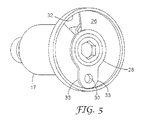
図1および図2によれば、触媒容器11は、触媒ペーストのための出口開口14を有する出口ソケット13を備え、同様に、基剤容器12は、基剤ペーストのための出口開口16を有する出口ソケット15を備える。ミキサ10は、管状ハウジング17と、出口ソケット13と接続するための第1接続ソケット18と、出口ソケット15と接続するための第2接続ソケット19と、を備える。ハウジング17は、混合チャンバ20を画定する。第1接続ソケット18および第2接続ソケット19は、それぞれ入口開口21および22を有し、それらは、ハウジング17の後端に取り付けられたベースプレート23から延在する。ダイナミックミキサ10は、さらに混合チャンバ20内に混合ロータを備えるが、これはより明確にするために図1および図2には示されていない。
According to FIGS. 1 and 2, the
図1において分かるように、第1流路(点線として表す)は、入口開口21から混合チャンバ20まで延在し、第2流路(破線として表す)は、入口開口22から混合チャンバ20まで延在する。さらに、第3流路(点線として表す)は、出口ソケット13を通して出口開口14まで延在し、第4流路(破線として表す)は、出口ソケット15を通して出口開口16まで延在する。ダイナミックミキサのスタイルが異なる場合、これらの流路は異なってもよく、そのため図面に示す流路は、サンプルとしての一組の流路を表すように意図されている。
As can be seen in FIG. 1, the first flow path (represented as a dotted line) extends from the inlet opening 21 to the mixing
図1の第1流路は、第1セグメントと第2セグメントとを備える。第1セグメントは、入口開口21で開始し、接続ソケット18を通ってベースプレート23まで延在し、一定の直径DImcの円形内部断面形状を有する。ここで、DImcは、入口開口21の内径である。第2セグメントは、第1セグメントに続き、ベースプレート23を通って混合チャンバ20まで延在し、また一定であるがより小さい、故に幅狭部分24を画定する直径Dmcの円形内部断面形状を有する。このため、第1流路は、幅狭部分24の断面積に対応しAmc=Dmc2/4*πからもたらされる最小断面積Amcを有する。
The first flow path in FIG. 1 includes a first segment and a second segment. The first segment starts at the
図1の第2流路は、入口開口22で開始し、接続ソケット19およびベースプレート23を通して混合チャンバ20まで延在し、一定の直径DImbの円形内部断面形状を有する。ここで、DImbは入口開口22の内径である。このため、第2流路は、第1流路に比較して、混合チャンバ20に向かって幅狭部分がなく、そのため入口開口22の断面積に対応しAmb=DImb2/4*πからもたらされる最小断面積Ambを有する。
The second flow path of FIG. 1 starts at the
しかしながら、図1には示さないが、第2流路は、第1流路の上記幅狭部分24のような幅狭部分を有してもよい。この場合、その最小断面積Ambは、それに従って、この幅狭部分の断面積に対応することになる。
However, although not shown in FIG. 1, the second channel may have a narrow portion such as the
図1の第3流路は、第1容器11の内側から出口開口14まで延在し、一定の直径DOccの円形内部断面形状を有する。ここでDOccは、出口開口14の内径である。このため、第3流路は、第2流路のように、出口開口14に向かって幅狭部分がなく、そのため、出口開口14の断面積に対応しAcc=DOcc2/4*πからもたらされる最小断面積Accを有する。
The third flow path in FIG. 1 extends from the inside of the
図1の第4流路は、同様に、第2容器12の内側から出口開口16まで延在し、一定の直径DOcbの円形内部断面形状を有する。ここで、DOcbは出口開口16の内径である。このため、第4流路は、第2流路のように、出口開口16に向かって幅狭部分がなく、そのため出口開口16の断面積に対応しAcb=DOcb2/4*πからもたらされる最小断面積Acbを有する。
Similarly, the fourth flow path of FIG. 1 extends from the inside of the
しかしながら、図1には示さないが、第3流路および第4流路の各々は、第1流路の上記幅狭部分24のような幅狭部分を有してもよい。この場合、最小断面積AccおよびAcbは、それにしたがって、それぞれの幅狭部分の断面積に対応することになる。
However, although not shown in FIG. 1, each of the third flow path and the fourth flow path may have a narrow portion such as the
図2において分かるように、出口ソケット13は接続ソケット18内に嵌合し、出口ソケット15は接続ソケット19の上に嵌合する。その結果、第1流路および第3流路ならびに第2流路および第4流路はそれぞれ結合され、それにより、第1全体流路(点線として表す)は、第1容器11の内側から混合チャンバ20まで延在し、第2全体流路(破線として表す)は、第2容器12の内側から混合チャンバ20まで延在する。
As can be seen in FIG. 2, the
図2の第1全体流路は、第1セグメントと第2セグメントとを備える。第1セグメントは、本実施形態では出口開口14が幅狭部分24を接合するように第1流路の第1セグメントを完全に充填する、出口ソケット13によって構成され、そのため第3流路に対応する。第2セグメントは第1セグメントに続き、幅狭部分24によって構成され、そのため、第1流路の第2セグメントに対応する。ここで、第1全体流路の最幅狭部分を、最小断面積AmcおよびAccを比較し、2つの面積のうちの小さい方を使用することによって確定してもよい。このため、第1全体流路は、上記最幅狭部分に対応しAoc=min(Amc,Acc)からもたらされる最小断面積Aocを有する。図2において分かるように、幅狭部分24の直径Dmcは、図示する例では出口開口14の直径DOccに等しく、そのためAoc=Amc=Accとなる。
The first entire flow path in FIG. 2 includes a first segment and a second segment. The first segment is constituted by an
図2の第2全体流路もまた、第1セグメントと第2セグメントとを備える。接続ソケット19は、出口ソケット15内に完全に嵌合するが、本実施形態ではそれを部分的にしか充填せず、第1セグメントは、接続ソケット19を覆わずまたは接続ソケット19によって充填されない出口ソケット15のその部分(すなわち、入口開口22の上の部分)によって構成され、そのため、容器12の内側から入口開口22まで延在する第4流路のその部分に対応する。第2セグメントは、第1セグメントに続き、接続ソケット19とベースプレート23の隣接部分とによって構成され、そのため、第2流路に対応する。ここで、第2全体流路の最幅狭部分を、最小断面積AmbおよびAcbを比較しそれら2つの面積のうちの小さい方を使用することによって確定してもよい。このため、第2全体流路は、上記最幅狭部分に対応しAob=min(Amb,Acb)からもたらされる最小断面積Aobを有する。図2において分かるように、入口開口22の直径DImbは、図示する例では出口開口16の直径DOcbより小さく、そのためAob=Ambである。
The second overall flow path of FIG. 2 also includes a first segment and a second segment. The
以下、提案されたミキサおよび容器の本発明者らによる検査の結果と本発明者らによる測定および評価の結果とを、図1および図2を参照してより詳細に説明する。 Hereinafter, the results of inspection of the proposed mixer and container by the inventors and the results of measurement and evaluation by the inventors will be described in more detail with reference to FIGS. 1 and 2.
ミキサに対する測定および評価の結果を、以下の表1で要約しその後で説明する。 The measurement and evaluation results for the mixer are summarized in Table 1 below and described below.

ミキサCWM1、DYM、GCM、KEM1、CWM2、KEM2、KAM、BIM、HKMおよび3MMの各々は、触媒ペーストのための第1または触媒流路と、基剤ペーストのための第2または基剤流路と、を示す。各触媒流路は、内径DImc=3.2mmである円形内部断面形状を有する入口開口21で開始するが、幅狭部分24がない。各基剤流路は、円形内部断面形状を有する入口開口22で開始し、幅狭部分はない。
Each of the mixers CWM1, DYM, GCM, KEM1, CWM2, KEM2, KAM, BIM, HKM and 3MM has a first or catalyst flow path for the catalyst paste and a second or base flow path for the base paste And. Each catalyst channel starts with an
ミキサCWM1、DYMおよびGCMは同じである。幅狭部分24は、内径Dmc=1.5mmの円形内部断面形状を有する。このため、触媒流路は、最小断面積Amc=1.8mm2である。入口開口22はDImb=6.8mmである。このため、基剤流路は、最小断面積Amb=36mm2である。
The mixers CWM1, DYM and GCM are the same. The
ミキサKEM1は、CWM1、DYMおよびGCMと同じ全体構造を有し、その幅狭部分24がDmc=2.0mmでありそのためAmc=3.1mm2であるという点が異なっている。
The mixer KEM1 has the same overall structure as CWM1, DYM and GCM, except that its
ミキサCWM2およびKEM2は同じであり、CWM1、DYM、GCMおよびKEM1と同様の全体構造を有する。それらは、幅狭部分24が半円断面形状を有するという点が異なる。このため、触媒流路は、最小断面積Amc=(DImc2/4*π)/2=4.0mm2である。それらは、さらに、入口開口22がDImb=6.9mmであり、そのためAmb=37mm2である、という点が異なる。
The mixers CWM2 and KEM2 are the same and have the same overall structure as CWM1, DYM, GCM and KEM1. They differ in that the
ミキサKAMは、図1のミキサ10と非常に類似する。幅狭部分24は、内径Dmc=1.2mmの円形内部断面形状を有し、そのためAmc=1.1mm2である。入口開口22はDImb=7.0mmであり、そのためAmb=38mm2である。
The mixer KAM is very similar to the
ミキサBIMおよびHKMは同じであり、図1のミキサ10に非常に類似する。幅狭部分24は内径Dmc=1.2mmの円形内部断面形状を有し、そのためAmc=1.1mm2である。入口開口22はDImb=6.9mmであり、このためAmb=37mm2である。
The mixers BIM and HKM are the same and are very similar to the
ミキサ3MMは図1のミキサ10に非常に類似する。幅狭部分24は、内径Dmc=1.6mmの円形内部断面形状を有し、このためAmc=2.0mm2である。入口開口22はDImb=6.3mmであり、このためAmb=31mm2である。
The mixer 3MM is very similar to the
本発明者らは、これらの値を比較し、提案されたミキサが、Amc4.0mm2以下の第1流路の最小断面積と、Amb/Amc=9.3以上の第2流路と第1流路との最小断面積の比と、を示すことが分かった。 The inventors have compared these values, and the proposed mixer has a minimum cross-sectional area of the first flow path of Amc 4.0 mm 2 or less, a second flow path of Amb / Amc = 9.3 or more, and the second flow path. It was found that the ratio of the minimum cross-sectional area to one flow path was shown.
容器対に対する測定および評価の結果を以下の表2に要約しその後で説明する。 The measurement and evaluation results for the container pair are summarized in Table 2 below and described below.
容器対CWC1、DYC、GCC、KEC、CWC2、KAC、BIC、HKC1、HKC2および3MCの各々は、図1の容器の対11、12と非常に類似しており、触媒ペーストのための第1または触媒容器11と、基剤ペーストのための第2または基剤容器12と、を備える。各触媒容器11は、出口ソケット13を通して延在する触媒ペーストのための第3または触媒流路を示す。各触媒流路は、一定の直径DOccの円形内部断面形状を有し、出口ソケット13を通して幅狭部分がなく、そのため最小断面積Acc=DOcc2/4*πである。各基剤容器12は、出口ソケット15を通して延在する基剤ペーストのための第4または基剤流路を示す。各基剤流路は、一定の直径DOcbの円形内部断面形状を有し、出口ソケット15を通して幅狭部分がなく、そのため、最小断面積Acb=DOcb2/4*πである。さらに、これらの容器対11、12の各々は、図2に示すようにその割り当てられたミキサ10と、すなわち出口ソケット13を接続ソケット18内にかつ出口ソケット15を接続ソケット19の上に嵌合させることによって、組み立てられる。
Each of the container pairs CWC1, DYC, GCC, KEC, CWC2, KAC, BIC, HKC1, HKC2 and 3MC are very similar to the container pairs 11, 12 of FIG. A
容器対CWC1は、DOcc=1.6mmであり故にAcc=2.0mm2である出口開口14を有する。出口開口16は、DOcb=8.6mmであり故にAcb=58mm2である。
The container pair CWC1 has an
容器対DYC、GCC、KECおよびCWC2は同じであり、CWC1と同じ全体構造を有する。それらは、DOcc=1.5mmであり故にAcc=1.8mm2である点、およびDOcb=8.5mmであり故にAcb=57mm2である点で異なる。 The container pairs DYC, GCC, KEC and CWC2 are the same and have the same overall structure as CWC1. They differ in that DOcc = 1.5 mm and hence Acc = 1.8 mm 2 and DOcb = 8.5 mm and hence Acb = 57 mm 2 .
容器対KACはDOcc=1.9mmであり、故にAcc=2.8mm2であり、それはDOcb=8.5mmであり、故にAcb=57mm2である。 The container pair KAC has DOcc = 1.9 mm, hence Acc = 2.8 mm 2 , which is DOcb = 8.5 mm, and thus Acb = 57 mm 2 .
容器対BICは、KACに類似する全体構造を有し、DOcc=2.2mmであり故にAcc=3.8mm2である点で異なる。 The container pair BIC has an overall structure similar to KAC, with the difference that DOcc = 2.2 mm and hence Acc = 3.8 mm 2 .
容器対HKC1はDOcc=2.0mmであり、故にAcc=3.1mm2であり、それはDOcb=8.5mmであり故にAcb=57mm2である。 The container pair HKC1 has DOcc = 2.0 mm, hence Acc = 3.1 mm 2 , which is DOcb = 8.5 mm and hence Acb = 57 mm 2 .
容器対HKC2は、HKC1と同じ全体構造を有し、DOcc=0.7mmであり故にAcc=0.4mm2である点で異なる。 The container pair HKC2 has the same overall structure as HKC1 and differs in that DOcc = 0.7 mm and hence Acc = 0.4 mm 2 .
容器対3MCはDOcc=1.2mmであり、故にAcc=1.1mm2であり、それはDOcb=8.6mmであり、故にAcb=58mm2である。 The container pair 3MC has DOcc = 1.2 mm, hence Acc = 1.1 mm 2 , which is DOcb = 8.6 mm, hence Acb = 58 mm 2 .
本発明者らは、これらの値を比較し、提案された容器対がAcc=3.8mm2以下の第3流路の最小断面積と、Acb/Acc=14.9以上の第4流路と第3流路との最小断面積の比率と、を示すことが分かった。 The inventors compare these values, and the proposed container pair has a minimum cross-sectional area of the third flow path of Acc = 3.8 mm 2 or less and a fourth flow path of Acb / Acc = 14.9 or more. And the ratio of the minimum cross-sectional area of the third flow path.
割り当てられたミキサおよび容器対のアセンブリに対する評価の結果を、以下の表3に要約しその後に説明する。 The results of the evaluation for the assigned mixer and container pair assembly are summarized in Table 3 below and described below.
本発明者らは、これらの値を比較し、割り当てられたミキサおよび容器対のアセンブリは、Aoc=1.8mm2以下の第1全体流路の最小断面積と、Aob/Aoc=21以上の第2全体流路と第1全体流路との最小断面積の比率と、を示すことが分かった。 The inventors have compared these values, and the assigned mixer and container pair assembly has a minimum cross-sectional area of the first overall flow path of Aoc = 1.8 mm 2 or less and Aob / Aoc = 21 or more. It was found that the ratio of the minimum cross-sectional area between the second general flow path and the first general flow path is shown.
ダイナミックミキサにおける、かつ本明細書で説明するタイプのシステムにおける性能の向上を、いくつかの部品をいくつかの幾何学的割合を用いて設計することにより得ることができると考えられる。これについては、概してかつ明確に後により詳細に説明する。 It is believed that improved performance in dynamic mixers and in systems of the type described herein can be obtained by designing several parts with several geometric ratios. This will be described in more detail later in general and clearly.
第1態様では、本発明は、少なくとも第1ペーストと第2ペーストとを混合して歯科用物質を生成するダイナミックミキサであって、
混合チャンバと、
第1ペーストのための入口開口と、
第2ペーストのための入口開口と、
第1ペーストのための入口開口から混合チャンバまで延在する第1流路と、
第2ペーストのための入口開口から混合チャンバまで延在する第2流路と、
を備え、
第1流路が、4.0mm2を上回る最小断面積を有し、
第2流路が、第1流路の最小断面積より大きい最小断面積を有する、ダイナミックミキサに関する。
In a first aspect, the present invention is a dynamic mixer for producing a dental material by mixing at least a first paste and a second paste,
A mixing chamber;
An inlet opening for the first paste;
An inlet opening for the second paste;
A first flow path extending from the inlet opening for the first paste to the mixing chamber;
A second flow path extending from the inlet opening for the second paste to the mixing chamber;
With
The first flow path has a minimum cross-sectional area greater than 4.0 mm 2 ;
The second mixer has a minimum cross-sectional area greater than the minimum cross-sectional area of the first flow path.
第2態様では、本発明は、少なくとも第1ペーストと第2ペーストとを混合して歯科用物質を生成するダイナミックミキサであって、
混合チャンバと、
第1ペーストのための入口開口と、
第2ペーストのための入口開口と、
第1ペーストのための入口開口から混合チャンバまで延在する第1流路と、
第2ペーストのための入口開口から混合チャンバまで延在する第2流路と、
を備え、
第2流路と第1流路との最小断面積が、1:1を上回りかつ9.3:1を下回る比率である、ダイナミックミキサに関する。
In a second aspect, the present invention is a dynamic mixer for producing a dental substance by mixing at least a first paste and a second paste,
A mixing chamber;
An inlet opening for the first paste;
An inlet opening for the second paste;
A first flow path extending from the inlet opening for the first paste to the mixing chamber;
A second flow path extending from the inlet opening for the second paste to the mixing chamber;
With
The present invention relates to a dynamic mixer in which the minimum cross-sectional area between the second flow path and the first flow path is a ratio that is greater than 1: 1 and less than 9.3: 1.
第3態様では、本発明は、第1ペーストを収容する第1容器と、第1ペーストと混合される第2ペーストを収容する第2容器と、の組合せであって、
第1容器が、
第1ペーストのための出口開口を備えた出口ソケットと、
出口ソケットを通して出口開口まで延在する第3流路と、
を備え、
第2容器が、
第2ペーストのための出口開口を備えた出口ソケットと、
出口ソケットを通して出口開口まで延在する第4流路と、
を備え、
それら容器が、少なくとも第1ペーストと第2ペーストとを混合して歯科用物質を生成するダイナミックミキサに接続されるように設計され、ミキサが、
混合チャンバと、
第1ペーストのための入口開口と、
第2ペーストのための入口開口と、
第1ペーストのための入口開口から混合チャンバまで延在する第1流路と、
第2ペーストのための入口開口から混合チャンバまで延在する第2流路と、
を備え、
第3流路が、3.8mm2を上回る最小断面積を有し、
第4流路が、第3流路の最小断面積より大きい最小断面積を有する、組合せに関する。
In a third aspect, the present invention is a combination of a first container that contains a first paste and a second container that contains a second paste to be mixed with the first paste,
The first container
An outlet socket with an outlet opening for the first paste;
A third flow path extending through the outlet socket to the outlet opening;
With
The second container
An outlet socket with an outlet opening for a second paste;
A fourth flow path extending through the outlet socket to the outlet opening;
With
The containers are designed to be connected to a dynamic mixer that mixes at least the first paste and the second paste to produce dental material,
A mixing chamber;
An inlet opening for the first paste;
An inlet opening for the second paste;
A first flow path extending from the inlet opening for the first paste to the mixing chamber;
A second flow path extending from the inlet opening for the second paste to the mixing chamber;
With
The third flow path has a minimum cross-sectional area greater than 3.8 mm 2 ;
The fourth channel relates to a combination having a minimum cross-sectional area that is greater than the minimum cross-sectional area of the third channel.
第4態様では、本発明は、第1ペーストを収容する第1容器と、第1ペーストと混合される第2ペーストを収容する第2容器と、の組合せに関し、
第1容器が、
第1ペーストのための出口開口を備えた出口ソケットと、
出口ソケットを通して出口開口まで延在する第3流路と、
を備え、
第2容器が、
第2ペーストのための出口開口を備えた出口ソケットと、
出口ソケットを通して出口開口まで延在する第4流路と、
を備え、
それら容器が、第1ペーストと第2ペーストとを混合して歯科用物質を生成するダイナミックミキサに接続されるように設計され、ミキサが、
混合チャンバと、
第1ペーストのための入口開口と、
第2ペーストのための入口開口と、
第1ペーストのための入口開口から混合チャンバまで延在する第1流路と、
第2ペーストのための入口開口から混合チャンバまで延在する第2流路と、
を備え、
第4流路と第3流路との最小断面積が、1:1を上回りかつ14.9:1を下回る比率である、組合せに関する。
In a fourth aspect, the present invention relates to a combination of a first container containing a first paste and a second container containing a second paste mixed with the first paste,
The first container
An outlet socket with an outlet opening for the first paste;
A third flow path extending through the outlet socket to the outlet opening;
With
The second container
An outlet socket with an outlet opening for a second paste;
A fourth flow path extending through the outlet socket to the outlet opening;
With
The containers are designed to be connected to a dynamic mixer that mixes the first paste and the second paste to produce a dental material,
A mixing chamber;
An inlet opening for the first paste;
An inlet opening for the second paste;
A first flow path extending from the inlet opening for the first paste to the mixing chamber;
A second flow path extending from the inlet opening for the second paste to the mixing chamber;
With
The minimum cross-sectional area of a 4th flow path and a 3rd flow path is related with the combination which is a ratio exceeding 1: 1 and less than 14.9: 1.
第5態様では、本発明は、少なくとも第1ペーストと第2ペーストとを混合して歯科用物質を生成するダイナミックミキサであって、
混合チャンバと、
第1ペーストのための入口開口と、
第2ペーストのための入口開口と、
第1ペーストのための入口開口から混合チャンバまで延在する第1流路と、
第2ペーストのための入口開口から混合チャンバまで延在する第2流路と、
を備え、
第1ペーストを収容する第1容器と第2ペーストを収容する第2容器とに接続されるように設計され、第1容器が、
第1ペーストのための出口開口を有する出口ソケットと、
出口ソケットを通して出口開口まで延在する第3流路と、
を備え、
第2容器が、
第2ペーストのための出口開口を有する出口ソケットと、
出口ソケットを通して出口開口まで延在する第4流路と、
を備え、
第1の容器がミキサに接続されると、第1全体流路が第1容器から混合チャンバまで延在し、
第2容器がミキサに接続されると、第2全体流路が第2容器から混合チャンバまで延在し、
第1全体流路が、1.8mm2を上回る最小断面積を有し、
第2全体流路が、第1全体流路の最小断面積より大きい最小断面積を有する、ダイナミックミキサに関する。
In a fifth aspect, the present invention is a dynamic mixer for producing a dental substance by mixing at least a first paste and a second paste,
A mixing chamber;
An inlet opening for the first paste;
An inlet opening for the second paste;
A first flow path extending from the inlet opening for the first paste to the mixing chamber;
A second flow path extending from the inlet opening for the second paste to the mixing chamber;
With
Designed to be connected to a first container containing a first paste and a second container containing a second paste, the first container is
An outlet socket having an outlet opening for the first paste;
A third flow path extending through the outlet socket to the outlet opening;
With
The second container
An outlet socket having an outlet opening for a second paste;
A fourth flow path extending through the outlet socket to the outlet opening;
With
When the first container is connected to the mixer, a first overall flow path extends from the first container to the mixing chamber;
When the second container is connected to the mixer, a second overall flow path extends from the second container to the mixing chamber;
The first overall flow path has a minimum cross-sectional area greater than 1.8 mm 2 ;
The second mixer has a minimum cross-sectional area that is larger than the minimum cross-sectional area of the first general channel.
第6態様では、本発明は、少なくとも第1ペーストと第2ペーストとを混合して歯科用物質を生成するダイナミックミキサであって、
混合チャンバと、
第1ペーストのための入口開口と、
第2ペーストのための入口開口と、
第1ペーストのための入口開口から混合チャンバまで延在する第1流路と、
第2ペーストのための入口開口から混合チャンバまで延在する第2流路と、
を備え、
第1ペーストを収容する第1容器と第2ペーストを収容する第2容器とに接続されるように設計され、第1容器が、
第1ペーストのための出口開口を有する出口ソケットと、
出口ソケットを通して出口開口まで延在する第3流路と、
を備え、
第2容器が、
第2ペーストのための出口開口を有する出口ソケットと、
出口ソケットを通して出口開口まで延在する第4流路と、
を備え、
第1の容器がミキサに接続されると、第1全体流路が第1容器から混合チャンバまで延在し、
第2容器がミキサに接続されると、第2全体流路が第2容器から混合チャンバまで延在し、
第2全体流路と第1全体流路との最小断面積が、1:1を上回りかつ20.6:1を下回る比率である、ダイナミックミキサに関する。
In a sixth aspect, the present invention is a dynamic mixer for producing a dental substance by mixing at least a first paste and a second paste,
A mixing chamber;
An inlet opening for the first paste;
An inlet opening for the second paste;
A first flow path extending from the inlet opening for the first paste to the mixing chamber;
A second flow path extending from the inlet opening for the second paste to the mixing chamber;
With
Designed to be connected to a first container containing a first paste and a second container containing a second paste, the first container is
An outlet socket having an outlet opening for the first paste;
A third flow path extending through the outlet socket to the outlet opening;
With
The second container
An outlet socket having an outlet opening for a second paste;
A fourth flow path extending through the outlet socket to the outlet opening;
With
When the first container is connected to the mixer, a first overall flow path extends from the first container to the mixing chamber;
When the second container is connected to the mixer, a second overall flow path extends from the second container to the mixing chamber;
The minimum cross-sectional area of a 2nd whole flow path and a 1st whole flow path is related with the dynamic mixer which is a ratio exceeding 1: 1 and less than 20.6: 1.
第7態様では、本発明は、第2ペーストと混合される第1ペーストを収容する容器であって、
第1ペーストのための出口開口を有する出口ソケットと、
出口ソケットを通して出口開口まで延在する第3流路と、
を備え、
第1ペーストと第2ペーストとを混合して歯科用物質を生成するダイナミックミキサと接続されるように設計され、ミキサが、
混合チャンバと、
第1ペーストのための入口開口と、
第2ペーストのための入口開口と、
第1ペーストのための入口開口から混合チャンバまで延在する第1流路と、
第2ペーストのための入口開口から混合チャンバまで延在する第2流路と、
を備え、
ミキサが、第2ペーストを収容する第2容器とに接続されるように設計され、第2容器が、
第2ペーストのための出口開口を有する出口ソケットと、
出口ソケットを通して出口開口まで延在する第4流路と、
を備え、
第1の容器がミキサに接続されると、第1全体流路が第1容器から混合チャンバまで延在し、
第2容器がミキサに接続されると、第2全体流路が第2容器から混合チャンバまで延在し、
第1全体流路が、1.8mm2を上回る最小断面積を有し、
第2全体流路が、第1全体流路の最小断面積より大きい最小断面積を有する、容器に関する。
In a seventh aspect, the present invention is a container for storing a first paste to be mixed with a second paste,
An outlet socket having an outlet opening for the first paste;
A third flow path extending through the outlet socket to the outlet opening;
With
Designed to be connected to a dynamic mixer that mixes a first paste and a second paste to produce a dental material,
A mixing chamber;
An inlet opening for the first paste;
An inlet opening for the second paste;
A first flow path extending from the inlet opening for the first paste to the mixing chamber;
A second flow path extending from the inlet opening for the second paste to the mixing chamber;
With
The mixer is designed to be connected to a second container containing a second paste, the second container being
An outlet socket having an outlet opening for a second paste;
A fourth flow path extending through the outlet socket to the outlet opening;
With
When the first container is connected to the mixer, a first overall flow path extends from the first container to the mixing chamber;
When the second container is connected to the mixer, a second overall flow path extends from the second container to the mixing chamber;
The first overall flow path has a minimum cross-sectional area greater than 1.8 mm 2 ;
The second overall flow path relates to a container having a minimum cross-sectional area greater than the minimum cross-sectional area of the first overall flow path.
第8態様では、本発明は、第2ペーストと混合される第1ペーストを収容する容器であって、
第1ペーストのための出口開口を有する出口ソケットと、
出口ソケットを通して出口開口まで延在する第3流路と、
を備え、
第1ペーストと第2ペーストとを混合して歯科用物質を生成するダイナミックミキサと接続されるように設計され、ミキサが、
混合チャンバと、
第1ペーストのための入口開口と、
第2ペーストのための入口開口と、
第1ペーストのための入口開口から混合チャンバまで延在する第1流路と、
第2ペーストのための入口開口から混合チャンバまで延在する第2流路と、
を備え、
ミキサが、第2ペーストを収容する第2容器と接続されるように設計され、第2容器が、
第2ペーストのための出口開口を有する出口ソケットと、
出口ソケットを通して出口開口まで延在する第4流路と、
を備え、
第1の容器がミキサに接続されると、第1全体流路が第1容器から混合チャンバまで延在し、
第2容器がミキサに接続されると、第2全体流路が第2容器から混合チャンバまで延在し、
第2全体流路と第1全体流路との最小断面積が、1:1を上回りかつ20.6:1を下回る比率である、容器に関する。
In an eighth aspect, the present invention is a container for storing a first paste to be mixed with a second paste,
An outlet socket having an outlet opening for the first paste;
A third flow path extending through the outlet socket to the outlet opening;
With
Designed to be connected to a dynamic mixer that mixes a first paste and a second paste to produce a dental material,
A mixing chamber;
An inlet opening for the first paste;
An inlet opening for the second paste;
A first flow path extending from the inlet opening for the first paste to the mixing chamber;
A second flow path extending from the inlet opening for the second paste to the mixing chamber;
With
The mixer is designed to be connected to a second container that contains a second paste, the second container
An outlet socket having an outlet opening for a second paste;
A fourth flow path extending through the outlet socket to the outlet opening;
With
When the first container is connected to the mixer, a first overall flow path extends from the first container to the mixing chamber;
When the second container is connected to the mixer, a second overall flow path extends from the second container to the mixing chamber;
The minimum cross-sectional area of a 2nd whole flow path and a 1st whole flow path is related with the container which is a ratio which exceeds 1: 1 and is less than 20.6: 1.
第9態様では、本発明は、ダイナミックミキサと、第1ペーストを収容する第1容器と、第1ペーストと混合される第2ペーストを収容する第2容器と、の組合せに関し、ミキサが、
混合チャンバと、
第1ペーストのための入口開口と、
第2ペーストのための入口開口と、
第1ペーストのための入口開口から混合チャンバまで延在する第1流路と、
第2ペーストのための入口開口から混合チャンバまで延在する第2流路と、
を備え、
第1容器が、
第1ペーストのための出口開口を備えた出口ソケットと、
出口ソケットを通して出口開口まで延在する第3流路と、を備え、出口ソケットが、第1容器から混合チャンバまで延在する第1全体流路を形成するようにミキサに接続され、
第2容器が、
第2ペーストのための出口開口を備えた出口ソケットと、
出口ソケットを通して出口開口まで延在する第4流路と、を備え、出口ソケットが、第2容器から混合チャンバまで延在する第2全体流路を形成するようにミキサに接続され、
第1全体流路が、1.8mm2を上回る最小断面積を有し、
第2全体流路が、第1全体流路の最小断面積より大きい最小断面積を有する、組合せに関する。
In a ninth aspect, the present invention relates to a combination of a dynamic mixer, a first container that contains a first paste, and a second container that contains a second paste to be mixed with the first paste.
A mixing chamber;
An inlet opening for the first paste;
An inlet opening for the second paste;
A first flow path extending from the inlet opening for the first paste to the mixing chamber;
A second flow path extending from the inlet opening for the second paste to the mixing chamber;
With
The first container
An outlet socket with an outlet opening for the first paste;
A third flow path extending through the outlet socket to the outlet opening, the outlet socket connected to the mixer to form a first general flow path extending from the first container to the mixing chamber;
The second container
An outlet socket with an outlet opening for a second paste;
A fourth flow path extending through the outlet socket to the outlet opening, the outlet socket connected to the mixer to form a second general flow path extending from the second container to the mixing chamber;
The first overall flow path has a minimum cross-sectional area greater than 1.8 mm 2 ;
The second overall flow path relates to a combination having a minimum cross-sectional area greater than the minimum cross-sectional area of the first overall flow path.
第10態様では、本発明は、ダイナミックミキサと、第1ペーストを収容する第1容器と、第1ペーストと混合される第2ペーストを収容する第2容器と、の組合せに関し、ミキサが、
混合チャンバと、
第1ペーストのための入口開口と、
第2ペーストのための入口開口と、
第1ペーストのための入口開口から混合チャンバまで延在する第1流路と、
第2ペーストのための入口開口から混合チャンバまで延在する第2流路と、
を備え、
第1容器が、
第1ペーストのための出口開口を備えた出口ソケットと、
出口ソケットを通して出口開口まで延在する第3流路と、を備え、出口ソケットが、第1容器から混合チャンバまで延在する第1全体流路を形成するようにミキサに接続され、
第2容器が、
第2ペーストのための出口開口を備えた出口ソケットと、
出口ソケットを通して出口開口まで延在する第4流路と、を備え、出口ソケットが、第2容器から混合チャンバまで延在する第2全体流路を形成するようにミキサに接続され、
第2全体流路と第1全体流路との最小断面積が、1:1を上回りかつ20.6:1を下回る比率である、組合せに関する。
In a tenth aspect, the present invention relates to a combination of a dynamic mixer, a first container that contains a first paste, and a second container that contains a second paste to be mixed with the first paste.
A mixing chamber;
An inlet opening for the first paste;
An inlet opening for the second paste;
A first flow path extending from the inlet opening for the first paste to the mixing chamber;
A second flow path extending from the inlet opening for the second paste to the mixing chamber;
With
The first container
An outlet socket with an outlet opening for the first paste;
A third flow path extending through the outlet socket to the outlet opening, the outlet socket connected to the mixer to form a first general flow path extending from the first container to the mixing chamber;
The second container
An outlet socket with an outlet opening for a second paste;
A fourth flow path extending through the outlet socket to the outlet opening, the outlet socket connected to the mixer to form a second general flow path extending from the second container to the mixing chamber;
The minimum cross-sectional area of a 2nd whole flow path and a 1st whole flow path is related with the combination whose ratio is more than 1: 1 and less than 20.6: 1.
第11態様によれば、本発明は、少なくとも1つのダイナミックミキサと、第1ペーストを収容する少なくとも1つの第1容器と、第1ペーストと混合される第2ペーストを収容する少なくとも1つの第2容器と、を備えるキットであって、ミキサが、
混合チャンバと、
第1ペーストのための入口開口と、
第2ペーストのための入口開口と、
第1ペーストのための入口開口から混合チャンバまで延在する第1流路と、
第2ペーストのための入口開口から混合チャンバまで延在する第2流路と、
を備え、
第1容器が、
第1ペーストのための出口開口を備えた出口ソケットと、
出口ソケットを通して出口開口まで延在する第3流路と、を備え、出口ソケットが、第1容器から混合チャンバまで延在する第1全体流路を形成するようにミキサに接続され、
第2容器が、
第2ペーストのための出口開口を備えた出口ソケットと、
出口ソケットを通して出口開口まで延在する第4流路と、を備え、出口ソケットが、第2容器から混合チャンバまで延在する第2全体流路を形成するようにミキサに接続され、
第1全体流路が、1.8mm2を上回る最小断面積を有し、
第2全体流路が、第1全体流路の最小断面積より大きい最小断面積を有する、キットに関する。
According to an eleventh aspect, the present invention provides at least one dynamic mixer, at least one first container containing a first paste, and at least one second containing a second paste mixed with the first paste. And a container, wherein the mixer is
A mixing chamber;
An inlet opening for the first paste;
An inlet opening for the second paste;
A first flow path extending from the inlet opening for the first paste to the mixing chamber;
A second flow path extending from the inlet opening for the second paste to the mixing chamber;
With
The first container
An outlet socket with an outlet opening for the first paste;
A third flow path extending through the outlet socket to the outlet opening, the outlet socket connected to the mixer to form a first general flow path extending from the first container to the mixing chamber;
The second container
An outlet socket with an outlet opening for a second paste;
A fourth flow path extending through the outlet socket to the outlet opening, the outlet socket connected to the mixer to form a second general flow path extending from the second container to the mixing chamber;
The first overall flow path has a minimum cross-sectional area greater than 1.8 mm 2 ;
The second overall flow path relates to a kit, wherein the second overall flow path has a minimum cross-sectional area greater than the minimum cross-sectional area of the first overall flow path.
第12態様によれば、本発明は、少なくとも1つのダイナミックミキサと、第1ペーストを収容する少なくとも1つの第1容器と、第1ペーストと混合される第2ペーストを収容する少なくとも1つの第2容器と、を備えるキットであって、ミキサが、
混合チャンバと、
第1ペーストのための入口開口と、
第2ペーストのための入口開口と、
第1ペーストのための入口開口から混合チャンバまで延在する第1流路と、
第2ペーストのための入口開口から混合チャンバまで延在する第2流路と、
を備え、
第1容器が、
第1ペーストのための出口開口を備えた出口ソケットと、
出口ソケットを通して出口開口まで延在する第3流路と、を備え、出口ソケットが、第1容器から混合チャンバまで延在する第1全体流路を形成するようにミキサに接続され、
第2容器が、
第2ペーストのための出口開口を備えた出口ソケットと、
出口ソケットを通して出口開口まで延在する第4流路と、を備え、出口ソケットが、第2容器から混合チャンバまで延在する第2全体流路を形成するようにミキサに接続され、
第2全体流路と第1全体流路との最小断面積が、1:1を上回りかつ20.6:1を下回る比率である、キットに関する。
According to a twelfth aspect, the present invention provides at least one dynamic mixer, at least one first container containing a first paste, and at least one second containing a second paste mixed with the first paste. And a container, wherein the mixer is
A mixing chamber;
An inlet opening for the first paste;
An inlet opening for the second paste;
A first flow path extending from the inlet opening for the first paste to the mixing chamber;
A second flow path extending from the inlet opening for the second paste to the mixing chamber;
With
The first container
An outlet socket with an outlet opening for the first paste;
A third flow path extending through the outlet socket to the outlet opening, the outlet socket connected to the mixer to form a first general flow path extending from the first container to the mixing chamber;
The second container
An outlet socket with an outlet opening for a second paste;
A fourth flow path extending through the outlet socket to the outlet opening, the outlet socket connected to the mixer to form a second general flow path extending from the second container to the mixing chamber;
The minimum cross-sectional area of a 2nd whole flow path and a 1st whole flow path is related with the kit which is a ratio which exceeds 1: 1 and is less than 20.6: 1.
本発明者らは、驚くべきことに、本発明によるダイナミックミキサ、組合せ、容器およびキットにより、逆汚染の危険を増大させることなく、分注中に第1ペーストの流動抵抗を、提案されたミキサおよび容器に比較して実質的に低減することができるということが分かった。さらに、本発明者らは、驚くべきことに、混合されるペーストの所望の容量混合比、たとえば上述した5:1の基剤対触媒容量混合比を、たとえばペンタミックス(PENTAMIX)TM2分注装置を使用する場合、維持することができる。 The inventors surprisingly found that the dynamic mixers, combinations, containers and kits according to the present invention provide the proposed mixer with the flow resistance of the first paste during dispensing without increasing the risk of back-contamination. And it has been found that it can be substantially reduced compared to containers. In addition, the inventors surprisingly found that the desired volume mixing ratio of the paste to be mixed, such as the 5: 1 base to catalyst volume mixing ratio described above, for example, PENTAMIX ™ 2 dispensing. When using the device, it can be maintained.
本発明は、流動抵抗が低減するために、ここで、同じ分注装置、たとえばペンタミックス(PENTAMIX)TM2分注装置を用いて、はるかに粘度が高いペーストを使用しかつ/またははるかに高速で通常のペーストを分注することが可能であるという利点を提供する。 The present invention now uses a much more viscous paste and / or much faster using the same dispenser, eg, PENTAMIX ™ 2 dispenser, because of the reduced flow resistance. Provides the advantage that it is possible to dispense a normal paste.
本発明は、(特許文献1)および(特許文献2)によって提案されたようなバッフルまたは方向変更要素が必要ではないというさらなる利点を提供する。しかしながら、本発明はまた、かかる要素を備えるミキサも包含する。 The present invention provides the further advantage that no baffles or redirection elements as proposed by US Pat. However, the invention also encompasses mixers comprising such elements.
混合されるペーストおよび混合された歯科用物質は、0.5mPas〜50MPas、特に1mPas〜10MPasの範囲の粘度を有してもよい。それらは、高粘性材料、すなわち、80mm未満の直径で測定されるDIN 4823クラス0〜3による粘稠度試験によって確定される粘度を有する材料であってもよい。 The mixed paste and the mixed dental material may have a viscosity in the range of 0.5 mPas to 50 MPas, in particular 1 mPas to 10 MPas. They may be highly viscous materials, i.e. materials having a viscosity determined by a consistency test according to DIN 4823 class 0-3 measured at a diameter of less than 80 mm.
本発明は、2つのペーストを混合することに制限されず、3つ以上のペーストの混合も包含する。 The present invention is not limited to mixing two pastes, but also includes mixing three or more pastes.
第1流路は、約4.0mm2以上、詳細には約4.1mm2以上、より詳細には約4.2mm2以上、より詳細には約4.3mm2以上の最小断面積を有することが可能である。 The first flow path is about 4.0 mm 2 or more, in particular about 4.1 mm 2 or above, more specifically about 4.2 mm 2 or more, more specifically having from about 4.3 mm 2 or more the minimum cross-sectional area of the It is possible.
第2流路と第1流路との最小断面積は、約9.3:1以下、詳細には約9.2:1以下、より詳細には約9.1:1以下、より詳細には約9:1以下、より詳細には約8:1以下、より詳細には約7.5:1以下、より詳細には約7:1以下、より詳細には約5:1以下、より詳細には約4.6:1以下、より詳細には約4.5:1以下、より詳細には約4.4:1以下の比率であることが可能である。 The minimum cross-sectional area of the second flow path and the first flow path is about 9.3: 1 or less, specifically about 9.2: 1 or less, more specifically about 9.1: 1 or less, more specifically Is about 9: 1 or less, more specifically about 8: 1 or less, more specifically about 7.5: 1 or less, more specifically about 7: 1 or less, more specifically about 5: 1 or less, more Specifically, the ratio can be about 4.6: 1 or less, more specifically about 4.5: 1 or less, and more specifically about 4.4: 1 or less.
第2流路と第1流路との最小断面積は、1:1を上回り、詳細には1.1:1以上、より詳細には1.2:1以上、より詳細には1.5:1以上、より詳細には2:1以上、より詳細には3:1以上、より詳細には4:1以上、より詳細には5:1以上、より詳細には6:1以上の比率であることが可能である。 The minimum cross-sectional area of the second flow path and the first flow path is greater than 1: 1, specifically 1.1: 1 or more, more specifically 1.2: 1 or more, and more specifically 1.5. 1 or more, more particularly 2: 1 or more, more particularly 3: 1 or more, more particularly 4: 1 or more, more particularly 5: 1 or more, more particularly 6: 1 or more. It is possible that
第1全体流路は、最小断面積が、1.8mm2を上回り、詳細には約1.9mm2以上、より詳細には約2.0mm2以上、より詳細には約3.0mm2以上、より詳細には約4.0mm2以上、より詳細には約5.0mm2以上、より詳細には約6.0mm2以上、より詳細には約6.2mm2以上、より詳細には約6.4mm2以上、より詳細には約7.0mm2以上であることが可能である。 The first overall flow path, the minimum cross-sectional area, greater than 1.8 mm 2, in particular about 1.9 mm 2 or above, more specifically about 2.0 mm 2 or more, about 3.0 mm 2 or more and more More specifically about 4.0 mm 2 or more, more specifically about 5.0 mm 2 or more, more specifically about 6.0 mm 2 or more, more specifically about 6.2 mm 2 or more, more specifically about It can be 6.4 mm 2 or more, more specifically about 7.0 mm 2 or more.
第2全体流路と第1全体流路との最小断面積は、約20.6:1以下、詳細には約20.3:1以下、より詳細には約20.0:1以下、より詳細には約19:1以下、より詳細には約18:1以下、より詳細には約16:1以下、より詳細には約13:1以下、より詳細には約10.6:1以下、より詳細には約10.4:1以下、より詳細には約10.2:1以下、より詳細には約10:1以下の比率であることが可能である。 The minimum cross-sectional area of the second general flow path and the first general flow path is about 20.6: 1 or less, specifically about 20.3: 1 or less, more specifically about 20.0: 1 or less, more More specifically about 19: 1 or less, more specifically about 18: 1 or less, more specifically about 16: 1 or less, more specifically about 13: 1 or less, and more specifically about 10.6: 1 or less. A ratio of about 10.4: 1 or less, more particularly about 10.2: 1 or less, and more specifically about 10: 1 or less.
第2全体流路と第1全体流路との最小断面積は、1:1を上回り、詳細には2:1以上、より詳細には3:1以上、より詳細には4:1以上、より詳細には6:1以上、より詳細には8:1以上、より詳細には10:1以上、より詳細には12:1以上、より詳細には14:1以上、より詳細には16:1以上の比率であることが可能である。 The minimum cross-sectional area of the second overall flow path and the first overall flow path is greater than 1: 1, specifically 2: 1 or more, more specifically 3: 1 or more, more specifically 4: 1 or more, More specifically 6: 1 or more, more specifically 8: 1 or more, more particularly 10: 1 or more, more particularly 12: 1 or more, more particularly 14: 1 or more, more specifically 16 The ratio can be 1 or more.
各流路は、任意の断面形状を有してもよい。たとえば、断面形状は、円形または半円形または楕円形または矩形または台形であってもよく、それは、サイズおよび/または形状が一定であってもよく、またはサイズおよび/または形状がその長さに沿って変化してもよい。 Each flow path may have an arbitrary cross-sectional shape. For example, the cross-sectional shape may be circular or semi-circular or oval or rectangular or trapezoidal, which may be constant in size and / or shape, or size and / or shape along its length May change.
さらに、各流路は、任意の進路、すなわち長手方向または流動方向の形状を有していてもよい。たとえば、進路は、直線状であっても、または湾曲していても、または屈曲していても、または折り重なっていても、または分岐していてもよく、もしくはかかるまたは任意の他の長手方向形状の1つまたは複数のセグメントを含んでもよい。 Furthermore, each flow path may have an arbitrary path, that is, a shape in a longitudinal direction or a flow direction. For example, the path may be straight, curved, bent, folded, or bifurcated, or such or any other longitudinal shape One or more segments.
遅延チャンバまたは遅延チャネル等の遅延セグメントが、流路のうちの任意のものの一部であってもよく、または流路のうちの任意のものに接続されていてもよい。かかる遅延セグメントは、空の混合チャンバの初期充填中に1つのペーストを別のペーストに対して遅延させることができる。たとえば、遅延チャンバおよび/または遅延チャネルは第2または基剤流路に続くことにより、基剤ペーストがより長い通路を流動して遅延チャンバまたはチャネルがない場合より遅く混合チャンバに入るようにしてもよい。それらは、優れた混合品質を達成するために、触媒ペーストが混合チャンバに入る時と基剤チャンバが混合チャンバに入る時との間の時間を望ましいように調整するのに役立つ。 A delay segment, such as a delay chamber or delay channel, may be part of any of the flow paths or may be connected to any of the flow paths. Such a delay segment can delay one paste relative to another during the initial filling of an empty mixing chamber. For example, the delay chamber and / or the delay channel may follow the second or base flow path so that the base paste flows through a longer path and enters the mixing chamber later than if there is no delay chamber or channel. Good. They help to adjust as desired the time between when the catalyst paste enters the mixing chamber and when the base chamber enters the mixing chamber in order to achieve superior mixing quality.
本発明のさらなる好ましい特徴および実施形態については特許請求の範囲に記載されている。 Further preferred features and embodiments of the invention are described in the claims.
本発明によるダイナミックミキサは、少なくとも第1ペーストと第2ペーストとを1:10以上および1:2以下の混合比で混合して歯科用物質を生成するために使用されることが可能である。 The dynamic mixer according to the present invention can be used to produce a dental material by mixing at least a first paste and a second paste in a mixing ratio of 1:10 or more and 1: 2 or less.
本発明によるダイナミックミキサまたは容器または組合せでは、第1全体流路の最小断面積が第1流路または第3流路に位置することが可能である。 In the dynamic mixer or container or combination according to the invention, the minimum cross-sectional area of the first overall flow path can be located in the first flow path or the third flow path.
本発明による組合せまたはキットは、ペーストを容器からミキサに送り出しミキサを駆動するモータ駆動分注装置をさらに備えることが可能である。 The combination or kit according to the present invention may further comprise a motor driven dispensing device that delivers paste from the container to the mixer and drives the mixer.
本発明による容器または組合せでは、第1ペーストを収容する容器が第1ペーストを収容しており、すなわち第1ペーストで充填されていることが可能である。 In the container or combination according to the invention, the container containing the first paste contains the first paste, ie it can be filled with the first paste.
本発明のよる組合せでは、第2ペーストを収容する容器が第2ペーストを収容しており、すなわち第2ペーストで充填されていることが可能である。 In the combination according to the invention, the container containing the second paste contains the second paste, ie it can be filled with the second paste.
本発明による容器または組合せは、上述した特許請求の範囲のうちの1つによる少なくとも1つのダイナミックミキサをさらに備えることが可能である。 The container or combination according to the invention can further comprise at least one dynamic mixer according to one of the above-mentioned claims.
本発明によれば、パッケージが、2つ以上、詳細には20以上、より詳細には50以上のダイナミックミキサを収容することが可能である。 According to the present invention, a package can contain two or more dynamic mixers, in particular 20 or more, more particularly 50 or more dynamic mixers.
本発明のさまざまな実施形態を、単に一例としての添付図面を参照して以下より詳細に説明する。 Various embodiments of the present invention will be described in more detail below with reference to the accompanying drawings, by way of example only.
図1および図2については、章「課題を解決するための手段」においてすでに上述したため、繰返しを避けるためにそれを参照する。 1 and 2 have already been described above in the chapter “Means for Solving the Problems”, so reference is made to avoid repetition.
しかしながら、図1および図2は、上述したミキサおよび容器の全般的な構造を概略的に示すのみでなく、第1実施形態におけるダイナミックミキサ10と第1実施形態における関連する一対の容器11、12と、も示す。本発明によるミキサ10および容器11、12のこれら第1実施形態は、触媒入口開口21および基剤入口開口22、幅狭部分24、触媒出口開口14および基剤出口開口16ならびに第1〜第4流路の以下の寸法において上述したミキサおよび容器から区別される。
However, FIGS. 1 and 2 not only schematically show the general structure of the mixer and container described above, but also the
したがって、本発明では、第1全体流路および第2全体流路の以下の寸法と比率とが適用される。 Therefore, in the present invention, the following dimensions and ratios of the first general flow path and the second general flow path are applied.
第1代替態様では、触媒入口開口21および基剤入口開口22、幅狭部分24、触媒出口開口14および基剤出口開口16ならびに第1〜第4流路の寸法は以下の通りである。
In the first alternative mode, the dimensions of the catalyst inlet opening 21 and the base inlet opening 22, the
したがって、第1全体流路および第2全体流路の以下の寸法および比率が適用される。 Accordingly, the following dimensions and ratios of the first overall flow path and the second overall flow path are applied.
第2代替態様では、触媒入口開口21および基剤入口開口22、幅狭部分24、触媒出口開口14および基剤出口開口16ならびに第1〜第4流路の寸法は以下の通りである。
In the second alternative embodiment, the dimensions of the catalyst inlet opening 21 and the base inlet opening 22, the
したがって、第1全体流路および第2全体流路の以下の寸法および比率が適用される。 Accordingly, the following dimensions and ratios of the first overall flow path and the second overall flow path are applied.
図3〜図6は、図1および図2の一対の容器11、12と協働する第2実施形態におけるダイナミックミキサ10を示す。
FIGS. 3-6 shows the
図3は、ハウジング17に回転可能に取り付けられた混合ロータ25を含むミキサ10を示し、図4は、より明確にするために混合ロータ25のないミキサ10を示す。
FIG. 3 shows the
図3および図4において分かるように、ミキサ10の全般的な構造は、図1および図2のミキサ10に非常に類似しており、後述するようにベースプレート23のレイアウトが主に異なる。
As can be seen in FIGS. 3 and 4, the general structure of the
ベースプレート23は、前部ディスク26と、後部ディスク27と、ディスク26、27を接続することによりそれらの間で遅延チャンバ29が画定されるようにするディスタンスピース28と、を備える。触媒接続ソケット18および基剤接続ソケット19は、後部ディスク27から延在し、それぞれ穴30において混合チャンバ20内に且つ穴31において遅延チャンバ29内に開口している。
The
図1のミキサ10と同様に、第1流路は、入口開口21で開始し、接続ソケット18およびベースプレート23を通して、より厳密には後部ディスク27、ディスタンスピース28および前部ディスク26を通して混合チャンバ20まで延在し、幅狭部分のようなもの(但し図3〜図6には示さず)を有する。
Similar to the
図1のミキサ10と同様に、第2流路は、入口開口22で開始し、接続ソケット19およびベースプレート23を通して混合チャンバ20まで延在する。より厳密には、前部ディスク26は穴32を有するため、第2流路は、穴31で後部ディスク27を出て遅延チャンバに入に入り、穴32で遅延チャンバを出る。
Similar to the
図4および図5において分かるように、穴32は、およそ台形形状を有し、その面積はAtrz=(a+b)*h/2である。ここで、aおよびbは、台形の長い辺と短い平行な辺とであり、hは台形の高さである。ミキサ10のこの第2実施形態では、穴32は以下の寸法を有する。すなわち、a=6.3mm、b=3.2mmおよびh=5.6mmであり、その結果Atrz=27mm2となり、ミキサ10のこの第2実施形態と容器11、12の第1実施形態とのアセンブリは、触媒入口開口21および基剤入口開口22、幅狭部分24、穴31、触媒出口開口14および基剤出口開口16ならびに第1〜第4流路の以下の寸法において従来のミキサおよび容器とは区別される。
As can be seen in FIGS. 4 and 5, the
したがって、第1全体流路および第2全体流路の以下の寸法および比率が適用される。 Accordingly, the following dimensions and ratios of the first overall flow path and the second overall flow path are applied.
第1代替態様では、触媒入口開口21および基剤入口開口22、幅狭部分24、穴31、触媒出口開口14および基剤出口開口16ならびに第1〜第4流路の寸法は以下の通りである。
In the first alternative embodiment, the dimensions of the catalyst inlet opening 21 and the base inlet opening 22, the
したがって、第1全体流路および第2全体流路の以下の寸法および比率が適用される。 Accordingly, the following dimensions and ratios of the first overall flow path and the second overall flow path are applied.
第2代替態様では、触媒入口開口21および基剤入口開口22、幅狭部分24、穴31、触媒出口開口14および基剤出口開口16ならびに第1〜第4流路の寸法は以下の通りである。
In the second alternative aspect, the dimensions of the catalyst inlet opening 21 and the base inlet opening 22, the
したがって、第1全体流路および第2全体流路の以下の寸法および比率が適用される。 Accordingly, the following dimensions and ratios of the first overall flow path and the second overall flow path are applied.
以下、遅延チャンバの機能について説明する。基剤ペーストは、基剤容器12から搾り出されると、基剤接続ソケット19および穴31を通って遅延チャンバ内に流れ込み、最初に、図5において2つの矢印によって示すように、ディスタンスピース28の端壁33によって停止されるまで、ミキサ10の長手方向軸の周りを右回り方向にかつ左回り方向に流れることによってそれを充填する。そして、基剤ペーストは、さらに穴32を通って混合チャンバ20に流れ込む。このため、基剤ペーストは、たとえば図1のミキサのように遅延チャンバがない場合(基剤ペーストは接続ソケット19から混合チャンバ20内に即座に流れ込む)より遅く混合チャンバに入る。
Hereinafter, the function of the delay chamber will be described. As the base paste is squeezed out of the
ミキサ10の第2実施形態では、穴32は、ミキサ10の長手方向軸を中心に穴31に対して角度が変位している(図5および図6を参照)。また、それは、角度がより多くまたは少なく変位しており、たとえば、部分的にまたは全体として穴31とオーバラップするかまたは1つの端壁33に隣接して位置することも可能である。さらに、穴32はここでは台形形状であるが、たとえば円形形状のように任意の形状であってもよい。さらに、前部ディスク26に2つ以上の穴32を設けてもよい。
In the second embodiment of the
ここでは、本発明について、そのいくつかの実施形態を参照して説明した。当業者には、本発明の範囲から逸脱することなく説明した実施形態において多くの変更を行うことができることが明らかとなろう。このため、本発明の範囲は、この出願で説明した構造に限定されるべきではなく、特許請求の範囲によって説明される構造およびそれら構造の等価物によってのみ限定されるべきである。 The present invention has been described herein with reference to several embodiments thereof. It will be apparent to those skilled in the art that many changes can be made in the embodiments described without departing from the scope of the invention. Thus, the scope of the present invention should not be limited to the structures described in this application, but only by the structures described by the claims and their equivalents.
10 ダイナミックミキサ
11 触媒容器
12 基剤容器
13 容器11の出口ソケット
14 容器11の出口開口
15 容器12の出口ソケット
16 容器12の出口開口
17 ハウジング
18 第1接続ソケット
19 第2接続ソケット
20 混合チャンバ
21 第1接続ソケット18の入口開口
22 第2接続ソケット19の入口開口
23 ベースプレート
24 幅狭部分
25 混合ロータ
26 前部ディスク
27 後部ディスク
28 ディスタンスピース
29 遅延チャンバ
30 前部ディスク26の穴
31 後部ディスク27の穴
32 前部ディスク26の穴
33 端壁
DImc 入口開口21の内径
Dmc 幅狭部分24の内径
Amc 第1流路の最小断面積
DImb 入口開口22の内径
Amb 第2流路の最小断面積
DOcc 出口開口14の内径
Acc 第3流路の最小断面積
DOcb 出口開口16の内径
Acb 第4流路の最小断面積
Aoc 第1全体流路の最小断面積
Aob 第2全体流路の最小断面積
DESCRIPTION OF
Claims (27)
混合チャンバ(20)と、
混合ロータ(25)と、
該第1ペーストのための入口開口(21)と、
該第2ペーストのための入口開口(22)と、
該第1ペーストのための該入口開口(21)から該混合チャンバ(20)まで延在する第1流路と、
該第1ペーストのための該入口開口(22)から該混合チャンバ(20)まで延在する第2流路と、
を備え、
該第1容器(11)が、
該第1ペーストのための出口開口(14)を備えた出口ソケット(13)と、
該出口ソケット(13)を通して該出口開口(14)まで延在する第3流路と、を備え、該出口ソケット(13)が、該第1容器(11)から該混合チャンバ(20)まで延在する第1全体流路を形成するように該ミキサ(10)に接続され、
該第2容器(12)が、
該第2ペーストのための出口開口(16)を備えた出口ソケット(15)と、
該出口ソケット(15)を通して該出口開口(16)まで延在する第4流路と、を備え、該出口ソケット(15)が、該第2容器(12)から該混合チャンバ(20)まで延在する第2全体流路を形成するように該ミキサ(10)に接続され、
該第1全体流路が、1.8mm2を上回る最小断面積(Aoc)を有し、
該第2全体流路が、該第1全体流路の該最小断面積(Aoc)より大きい最小断面積(Aob)を有する、組合せ。 A combination of a dynamic mixer (10), a first container (11) containing a first paste, and a second container (12) containing a second paste mixed with the first paste, The mixer (10)
A mixing chamber (20);
A mixing rotor (25);
An inlet opening (21) for the first paste;
An inlet opening (22) for the second paste;
A first flow path extending from the inlet opening (21) for the first paste to the mixing chamber (20);
A second flow path extending from the inlet opening (22) for the first paste to the mixing chamber (20);
With
The first container (11)
An outlet socket (13) with an outlet opening (14) for the first paste;
A third flow path extending through the outlet socket (13) to the outlet opening (14), the outlet socket (13) extending from the first container (11) to the mixing chamber (20). Connected to the mixer (10) to form an existing first general flow path;
The second container (12)
An outlet socket (15) with an outlet opening (16) for the second paste;
A fourth flow path extending through the outlet socket (15) to the outlet opening (16), the outlet socket (15) extending from the second container (12) to the mixing chamber (20). Connected to the mixer (10) to form an existing second overall flow path;
The first overall flow path has a minimum cross-sectional area (Aoc) greater than 1.8 mm 2 ;
A combination wherein the second overall flow path has a minimum cross-sectional area (Aob) that is greater than the minimum cross-sectional area (Aoc) of the first overall flow path.
混合チャンバ(20)と、
混合ロータ(25)と、
該第1ペーストのための入口開口(21)と、
該第2ペーストのための入口開口(22)と、
該第1ペーストのための該入口開口(21)から該混合チャンバ(20)まで延在する第1流路と、
該第1ペーストのための該入口開口(22)から該混合チャンバ(20)まで延在する第2流路と、
を備え、
該第1容器(11)が、
該第1ペーストのための出口開口(14)を備えた出口ソケット(13)と、
該出口ソケット(13)を通して該出口開口(14)まで延在する第3流路と、を備え、該出口ソケット(13)が、該第1容器(11)から該混合チャンバ(20)まで延在する第1全体流路を形成するように該ミキサ(10)に接続され、
該第2容器(12)が、
該第2ペーストのための出口開口(16)を備えた出口ソケット(15)と、
該出口ソケット(15)を通して該出口開口(16)まで延在する第4流路と、を備え、該出口ソケット(15)が、該第2容器(12)から該混合チャンバ(20)まで延在する第2全体流路を形成するように該ミキサ(10)に接続され、
該第2全体流路と該第1全体流路との最小断面積(Aob、Aoc)が、1:1を上回りかつ20.6:1を下回る比率である、組合せ。 A combination of a dynamic mixer (10), a first container (11) containing a first paste, and a second container (12) containing a second paste to be mixed with the first paste, the mixer (10)
A mixing chamber (20);
A mixing rotor (25);
An inlet opening (21) for the first paste;
An inlet opening (22) for the second paste;
A first flow path extending from the inlet opening (21) for the first paste to the mixing chamber (20);
A second flow path extending from the inlet opening (22) for the first paste to the mixing chamber (20);
With
The first container (11)
An outlet socket (13) with an outlet opening (14) for the first paste;
A third flow path extending through the outlet socket (13) to the outlet opening (14), the outlet socket (13) extending from the first container (11) to the mixing chamber (20). Connected to the mixer (10) to form an existing first general flow path;
The second container (12)
An outlet socket (15) with an outlet opening (16) for the second paste;
A fourth flow path extending through the outlet socket (15) to the outlet opening (16), the outlet socket (15) extending from the second container (12) to the mixing chamber (20). Connected to the mixer (10) to form an existing second overall flow path;
A combination in which the minimum cross-sectional area (Aob, Aoc) of the second general flow path and the first general flow path is a ratio that is greater than 1: 1 and less than 20.6: 1.
混合チャンバ(20)と、
混合ロータ(25)と、
該第1ペーストのための入口開口(21)と、
該第2ペーストのための入口開口(22)と、
該第1ペーストのための該入口開口(21)から該混合チャンバ(20)まで延在する第1流路と、
該第2ペーストのための該入口開口(22)から該混合チャンバ(20)まで延在する第2流路と、
を備え、
該第1ペーストを収容する第1容器(11)と該第2ペーストを収容する第2容器(12)とに接続されるように設計され、該第1容器(11)が、
該第1ペーストのための出口開口(14)を有する出口ソケット(13)と、
該出口ソケット(13)を通して該出口開口まで延在する第3流路と、
を備え、
該第2容器(12)が、
該第2ペーストのための出口開口(16)を有する出口ソケット(15)と、
該出口ソケット(15)を通して該出口開口まで延在する第4流路と、
を備え、
該第1の容器(11)が当該ミキサ(10)に接続されると、第1全体流路が該第1容器(11)から該混合チャンバ(20)まで延在し、
該第2容器(12)が当該ミキサ(10)に接続されると、第2全体流路が該第2容器(12)から該混合チャンバ(20)まで延在し、
該第1全体流路が、1.8mm2を上回る最小断面積(Aoc)を有し、
該第2全体流路が、該第1全体流路の該最小断面積(Aoc)より大きい最小断面積(Aob)を有する、ダイナミックミキサ。 A dynamic mixer (10) for producing a dental material by mixing at least a first paste and a second paste,
A mixing chamber (20);
A mixing rotor (25);
An inlet opening (21) for the first paste;
An inlet opening (22) for the second paste;
A first flow path extending from the inlet opening (21) for the first paste to the mixing chamber (20);
A second flow path extending from the inlet opening (22) for the second paste to the mixing chamber (20);
With
Designed to be connected to a first container (11) containing the first paste and a second container (12) containing the second paste, the first container (11)
An outlet socket (13) having an outlet opening (14) for the first paste;
A third flow path extending through the outlet socket (13) to the outlet opening;
With
The second container (12)
An outlet socket (15) having an outlet opening (16) for the second paste;
A fourth flow path extending through the outlet socket (15) to the outlet opening;
With
When the first container (11) is connected to the mixer (10), a first overall flow path extends from the first container (11) to the mixing chamber (20),
When the second container (12) is connected to the mixer (10), a second overall flow path extends from the second container (12) to the mixing chamber (20),
The first overall flow path has a minimum cross-sectional area (Aoc) greater than 1.8 mm 2 ;
A dynamic mixer, wherein the second overall flow path has a minimum cross-sectional area (Aob) that is greater than the minimum cross-sectional area (Aoc) of the first overall flow path.
混合チャンバ(20)と、
混合ロータ(25)と、
該第1ペーストのための入口開口(21)と、
該第2ペーストのための入口開口(22)と、
該第1ペーストのための該入口開口(21)から該混合チャンバ(20)まで延在する第1流路と、
該第2ペーストのための該入口開口(22)から該混合チャンバ(20)まで延在する第2流路と、
を備え、
該第1ペーストを収容する第1容器(11)と該第2ペーストを収容する第2容器(12)とに接続されるように設計され、該第1容器(11)が、
該第1ペーストのための出口開口(14)を有する出口ソケット(13)と、
該出口ソケット(13)を通して該出口開口まで延在する第3流路と、
を備え、
該第2容器(12)が、
該第2ペーストのための出口開口(16)を有する出口ソケット(15)と、
該出口ソケット(15)を通して該出口開口まで延在する第4流路と、
を備え、
該第1の容器(11)が当該ミキサ(10)に接続されると、第1全体流路が該第1容器(11)から該混合チャンバ(20)まで延在し、
該第2容器(12)が当該ミキサ(10)に接続されると、第2全体流路が該第2容器(12)から該混合チャンバ(20)まで延在し、
該第2全体流路と該第1全体流路との最小断面積(Aob、Aoc)が、1:1を上回りかつ20.6:1を下回る比率である、ダイナミックミキサ。 A dynamic mixer (10) for producing a dental material by mixing at least a first paste and a second paste,
A mixing chamber (20);
A mixing rotor (25);
An inlet opening (21) for the first paste;
An inlet opening (22) for the second paste;
A first flow path extending from the inlet opening (21) for the first paste to the mixing chamber (20);
A second flow path extending from the inlet opening (22) for the second paste to the mixing chamber (20);
With
Designed to be connected to a first container (11) containing the first paste and a second container (12) containing the second paste, the first container (11)
An outlet socket (13) having an outlet opening (14) for the first paste;
A third flow path extending through the outlet socket (13) to the outlet opening;
With
The second container (12)
An outlet socket (15) having an outlet opening (16) for the second paste;
A fourth flow path extending through the outlet socket (15) to the outlet opening;
With
When the first container (11) is connected to the mixer (10), a first overall flow path extends from the first container (11) to the mixing chamber (20),
When the second container (12) is connected to the mixer (10), a second overall flow path extends from the second container (12) to the mixing chamber (20),
A dynamic mixer in which a minimum cross-sectional area (Aob, Aoc) between the second general flow path and the first general flow path is a ratio that is greater than 1: 1 and less than 20.6: 1.
該第1ペーストのための出口開口(14)を有する出口ソケット(13)と、
該出口ソケット(13)を通して該出口開口まで延在する第3流路と、
を備え、
請求項3に記載のダイナミックミキサ(10)と接続されるように設計される、容器。 A container (11) containing a first paste to be mixed with a second paste,
An outlet socket (13) having an outlet opening (14) for the first paste;
A third flow path extending through the outlet socket (13) to the outlet opening;
With
A container designed to be connected to a dynamic mixer (10) according to claim 3.
該第1ペーストのための出口開口(14)を有する出口ソケット(13)と、
該出口ソケット(13)を通して該出口開口(14)まで延在する第3流路と、
を備え、
請求項4に記載のダイナミックミキサ(10)と接続されるように設計される、容器。 A container (11) containing a first paste to be mixed with a second paste,
An outlet socket (13) having an outlet opening (14) for the first paste;
A third flow path extending through the outlet socket (13) to the outlet opening (14);
With
A container designed to be connected to a dynamic mixer (10) according to claim 4.
該第1容器(11)が、
該第1ペーストのための出口開口(14)を備えた出口ソケット(13)と、
該出口ソケット(13)を通して該出口開口(14)まで延在する第3流路と、を備え、該出口ソケット(13)が、該第1容器(11)から該混合チャンバ(20)まで延在する第1全体流路を形成するように該ミキサ(10)に接続され、
該第2容器(12)が、
該第2ペーストのための出口開口(16)を備えた出口ソケット(15)と、
該出口ソケット(15)を通して該出口開口(16)まで延在する第4流路と、を備え、該出口ソケット(15)が、該第2容器(12)から該混合チャンバ(20)まで延在する第2全体流路を形成するように該ミキサ(10)に接続される、キット。 4. At least one dynamic mixer (10) according to claim 3, at least one first container (11) containing a first paste, and at least one containing a second paste mixed with the first paste. A second container (12), comprising:
The first container (11)
An outlet socket (13) with an outlet opening (14) for the first paste;
A third flow path extending through the outlet socket (13) to the outlet opening (14), the outlet socket (13) extending from the first container (11) to the mixing chamber (20). Connected to the mixer (10) to form an existing first general flow path;
The second container (12)
An outlet socket (15) with an outlet opening (16) for the second paste;
A fourth flow path extending through the outlet socket (15) to the outlet opening (16), the outlet socket (15) extending from the second container (12) to the mixing chamber (20). A kit connected to the mixer (10) to form an existing second overall flow path.
該第1容器(11)が、
該第1ペーストのための出口開口(14)を備えた出口ソケット(13)と、
該出口ソケット(13)を通して該出口開口(14)まで延在する第3流路と、を備え、該出口ソケット(13)が、該第1容器(11)から該混合チャンバ(20)まで延在する第1全体流路を形成するように該ミキサ(10)に接続され、
該第2容器(12)が、
該第2ペーストのための出口開口(16)を備えた出口ソケット(15)と、
該出口ソケット(15)を通して該出口開口(16)まで延在する第4流路と、を備え、該出口ソケット(15)が、該第2容器(12)から該混合チャンバ(20)まで延在する第2全体流路を形成するように該ミキサ(10)に接続される、キット。 5. At least one dynamic mixer (10) according to claim 4, at least one first container (11) containing paste K, and at least one first containing a second paste mixed with said first paste. A kit comprising two containers (12),
The first container (11)
An outlet socket (13) with an outlet opening (14) for the first paste;
A third flow path extending through the outlet socket (13) to the outlet opening (14), the outlet socket (13) extending from the first container (11) to the mixing chamber (20). Connected to the mixer (10) to form an existing first general flow path;
The second container (12)
An outlet socket (15) with an outlet opening (16) for the second paste;
A fourth flow path extending through the outlet socket (15) to the outlet opening (16), the outlet socket (15) extending from the second container (12) to the mixing chamber (20). A kit connected to the mixer (10) to form an existing second overall flow path.
混合チャンバ(20)と、
混合ロータ(25)と、
該第1ペーストのための入口開口(21)と、
該第2ペーストのための入口開口(22)と、
該第1ペーストのための該入口開口(21)から該混合チャンバ(20)まで延在する第1流路と、
該第2ペーストのための該入口開口(22)から該混合チャンバ(20)まで延在する第2流路と、
を備え、
該第1流路が、4.0mm2を上回る最小断面積(Amc)を有し、
該第2流路が、該第1流路の該最小断面積(Amc)より大きい最小断面積(Amb)を有する、ダイナミックミキサ。 A dynamic mixer that mixes at least a first paste and a second paste to produce a dental substance,
A mixing chamber (20);
A mixing rotor (25);
An inlet opening (21) for the first paste;
An inlet opening (22) for the second paste;
A first flow path extending from the inlet opening (21) for the first paste to the mixing chamber (20);
A second flow path extending from the inlet opening (22) for the second paste to the mixing chamber (20);
With
The first flow path has a minimum cross-sectional area (Amc) greater than 4.0 mm 2 ;
The dynamic mixer, wherein the second flow path has a minimum cross-sectional area (Amb) greater than the minimum cross-sectional area (Amc) of the first flow path.
混合チャンバ(20)と、
混合ロータ(25)と、
該第1ペーストのための入口開口(21)と、
該第2ペーストのための入口開口(22)と、
該第1ペーストのための該入口開口(21)から該混合チャンバ(20)まで延在する第1流路と、
該第2ペーストのための該入口開口(22)から該混合チャンバ(20)まで延在する第2流路と、
を備え、
該第2全体流路と該第1全体流路との最小断面積(Amb、Amc)が、1:1を上回りかつ9.3:1を下回る比率である、ダイナミックミキサ。 A dynamicmic mixer (10) for producing a dental material by mixing at least a first paste and a second paste,
A mixing chamber (20);
A mixing rotor (25);
An inlet opening (21) for the first paste;
An inlet opening (22) for the second paste;
A first flow path extending from the inlet opening (21) for the first paste to the mixing chamber (20);
A second flow path extending from the inlet opening (22) for the second paste to the mixing chamber (20);
With
A dynamic mixer in which a minimum cross-sectional area (Amb, Amc) between the second whole flow path and the first whole flow path is a ratio that is greater than 1: 1 and less than 9.3: 1.
該第1ペーストのための出口開口(14)を有する出口ソケット(13)と、
該出口ソケット(13)を通して該出口開口まで延在する第3流路と、
を備え、
該第2容器(12)が、
該第2ペーストのための出口開口(16)を有する出口ソケット(15)と、
該出口ソケット(15)を通して該出口開口まで延在する第4流路と、
を備え、
該容器(11、12)が、少なくとも第1ペーストと第2ペーストとを混合して歯科用物質を生成するダイナミックミキサ(10)と接続されるように設計され、該ミキサ(10)が、
混合チャンバ(20)と、
混合ロータ(25)と、
該第1ペーストのための入口開口(21)と、
該第2ペーストのための入口開口(22)と、
該第1ペーストのための該入口開口(21)から該混合チャンバ(20)まで延在する第1流路と、
該第2ペーストのための該入口開口(22)から該混合チャンバ(20)まで延在する第2流路と、
を備え、
該第3流路が、3.8mm2を上回る最小断面積(Acc)を有し、
該第4流路が、該第3流路全体の該最小断面積(Acc)より大きい最小断面積(Acb)を有する、組合せ。 A combination of a first container (11) containing a first paste and a second container (12) containing a second paste to be mixed with the first paste, the first container (11) being ,
An outlet socket (13) having an outlet opening (14) for the first paste;
A third flow path extending through the outlet socket (13) to the outlet opening;
With
The second container (12)
An outlet socket (15) having an outlet opening (16) for the second paste;
A fourth flow path extending through the outlet socket (15) to the outlet opening;
With
The container (11, 12) is designed to be connected to a dynamic mixer (10) that mixes at least a first paste and a second paste to produce a dental material, the mixer (10) comprising:
A mixing chamber (20);
A mixing rotor (25);
An inlet opening (21) for the first paste;
An inlet opening (22) for the second paste;
A first flow path extending from the inlet opening (21) for the first paste to the mixing chamber (20);
A second flow path extending from the inlet opening (22) for the second paste to the mixing chamber (20);
With
The third flow path has a minimum cross-sectional area (Acc) greater than 3.8 mm 2 ;
The combination wherein the fourth flow path has a minimum cross-sectional area (Acb) that is greater than the minimum cross-sectional area (Acc) of the entire third flow path.
該第1ペーストのための出口開口(14)を有する出口ソケット(13)と、
該出口ソケット(13)を通して該出口開口まで延在する第3流路と、
を備え、
該第2容器(12)が、
該第2ペーストのための出口開口(16)を有する出口ソケット(15)と、
該出口ソケット(15)を通して該出口開口まで延在する第4流路と、
を備え、
該容器(11、12)が、少なくとも第1ペーストと第2ペーストとを混合して歯科用物質を生成するダイナミックミキサ(10)と接続されるように設計され、該ミキサ(10)が、
混合チャンバ(20)と、
混合ロータ(25)と、
該第1ペーストのための入口開口(21)と、
該第2ペーストのための入口開口(22)と、
該第1ペーストのための該入口開口(21)から該混合チャンバ(20)まで延在する第1流路と、
該第2ペーストのための該入口開口(22)から該混合チャンバ(20)まで延在する第2流路と、
を備え、
該第4流路全体と該第3流路全体との最小断面積(Acb、Acc)が、1:1を上回りかつ14.9:1を下回る比率である、組合せ。 A combination of a first container (11) containing a first paste and a second container (12) containing a second paste to be mixed with the first paste, the first container (11) being ,
An outlet socket (13) having an outlet opening (14) for the first paste;
A third flow path extending through the outlet socket (13) to the outlet opening;
With
The second container (12)
An outlet socket (15) having an outlet opening (16) for the second paste;
A fourth flow path extending through the outlet socket (15) to the outlet opening;
With
The container (11, 12) is designed to be connected to a dynamic mixer (10) that mixes at least a first paste and a second paste to produce a dental material, the mixer (10) comprising:
A mixing chamber (20);
A mixing rotor (25);
An inlet opening (21) for the first paste;
An inlet opening (22) for the second paste;
A first flow path extending from the inlet opening (21) for the first paste to the mixing chamber (20);
A second flow path extending from the inlet opening (22) for the second paste to the mixing chamber (20);
With
A combination in which the minimum cross-sectional area (Acb, Acc) of the entire fourth channel and the entire third channel is a ratio that is greater than 1: 1 and less than 14.9: 1.
Applications Claiming Priority (2)
| Application Number | Priority Date | Filing Date | Title |
|---|---|---|---|
| EP04009218A EP1588779A1 (en) | 2004-04-19 | 2004-04-19 | Dynamic mixer |
| PCT/EP2005/004119 WO2005099913A1 (en) | 2004-04-19 | 2005-04-18 | Combination of dynamic mixer and containers |
Publications (2)
| Publication Number | Publication Date |
|---|---|
| JP2007532311A true JP2007532311A (en) | 2007-11-15 |
| JP2007532311A5 JP2007532311A5 (en) | 2008-05-15 |
Family
ID=34924652
Family Applications (1)
| Application Number | Title | Priority Date | Filing Date |
|---|---|---|---|
| JP2007508817A Withdrawn JP2007532311A (en) | 2004-04-19 | 2005-04-18 | Dynamic mixer and container combination |
Country Status (7)
| Country | Link |
|---|---|
| US (2) | US20050232073A1 (en) |
| EP (2) | EP1588779A1 (en) |
| JP (1) | JP2007532311A (en) |
| CN (1) | CN1968761A (en) |
| AU (1) | AU2005232886A1 (en) |
| CA (1) | CA2562876A1 (en) |
| WO (1) | WO2005099913A1 (en) |
Cited By (2)
| Publication number | Priority date | Publication date | Assignee | Title |
|---|---|---|---|---|
| JP2011521670A (en) * | 2007-09-10 | 2011-07-28 | スルザー ミックスパック アクチェンゲゼルシャフト | Dynamic mixer |
| JP2014087790A (en) * | 2012-10-23 | 2014-05-15 | Nordson Corp | Dispensing assembly and method for dispensing mixed fluid |
Families Citing this family (17)
| Publication number | Priority date | Publication date | Assignee | Title |
|---|---|---|---|---|
| DE10112904C5 (en) | 2001-03-15 | 2010-04-22 | 3M Espe Ag | Dynamic mixer and method for mixing at least two paste components |
| JP2006519699A (en) * | 2003-03-06 | 2006-08-31 | デンツプライ インターナショナル インコーポレーテッド | Dispensing and mixing tips |
| DE60300822T2 (en) * | 2003-08-14 | 2006-04-13 | 3M Espe Ag | Mixing element for a multi-component paste mixer, and mixer with this mixing element |
| WO2005082549A2 (en) * | 2004-02-27 | 2005-09-09 | Heraeus Kulzer Gmbh | Method for the production of dental moulding materials and device therefor |
| EP1588779A1 (en) * | 2004-04-19 | 2005-10-26 | 3M Espe AG | Dynamic mixer |
| EP1640060A1 (en) | 2004-09-22 | 2006-03-29 | 3M Espe Ag | Mixer for multi-component pastes, kit, and method of mixing paste components |
| US8322909B2 (en) * | 2004-09-22 | 2012-12-04 | 3M Deutschland Gmbh | Mixer for multi-component pastes, kit, and method of mixing paste components |
| CA2672200C (en) * | 2006-12-15 | 2015-01-13 | 3M Innovative Properties Company | Mixing and dispensing curable multi-component materials |
| US7731413B2 (en) * | 2008-02-20 | 2010-06-08 | Zhermack S.P.A. | Mixer for multi-components substance for dental casting |
| GB0922294D0 (en) * | 2009-12-22 | 2010-02-03 | 3M Innovative Properties Co | A dispensing device for a dental material and a method of filling the device |
| DE102010019771A1 (en) * | 2010-05-07 | 2011-11-10 | Dürr Systems GmbH | Atomizer with a lattice mixer |
| KR101091062B1 (en) * | 2011-07-04 | 2011-12-08 | (주) 세일덴텍 | A mixing tip of automatic style dental impression material |
| CN102513265A (en) * | 2011-12-06 | 2012-06-27 | 上海义馨控制设备有限公司 | Glue-pouring integrated machine and coating method thereof |
| FR2998551B1 (en) * | 2012-11-26 | 2015-05-22 | Oreal | DEVICE AND METHOD FOR FILLING A CONTAINER |
| KR101355130B1 (en) * | 2013-04-25 | 2014-01-27 | (주)디엑스엠 | Impression mixing tip |
| KR101406068B1 (en) * | 2013-09-05 | 2014-06-11 | (주)디엑스엠 | Impression mixing tip |
| CN108273702A (en) * | 2018-01-05 | 2018-07-13 | 佛山杰致信息科技有限公司 | A kind of point glue equipment during electronic components fabrication |
Family Cites Families (81)
| Publication number | Priority date | Publication date | Assignee | Title |
|---|---|---|---|---|
| US175186A (en) * | 1876-03-21 | Improvement in washing-machines | ||
| US190082A (en) * | 1877-04-24 | Improvement in apparatus for cooling liquids | ||
| US123323A (en) * | 1872-02-06 | Improvement in cigar-molds | ||
| US2816518A (en) * | 1956-01-10 | 1957-12-17 | Daggett Chocolate Company | Ice cream blending apparatus |
| US3051455A (en) * | 1960-07-25 | 1962-08-28 | Gen Electric | Mixing nozzle |
| BE625883A (en) * | 1961-12-08 | |||
| DE1486405A1 (en) * | 1965-04-15 | 1969-06-04 | H V Hardman Company Inc | Device for mixing and dispensing materials |
| US3390814A (en) * | 1965-09-24 | 1968-07-02 | Chem Dev Corp | Mixing device |
| US3570719A (en) * | 1968-07-02 | 1971-03-16 | Louis Schiff | Reagent mixing and dispensing apparatus |
| US3570716A (en) * | 1968-11-04 | 1971-03-16 | Continental Can Co | Fluidizer and dispenser |
| US3587982A (en) * | 1969-01-15 | 1971-06-28 | Ncr Co | Adhesive and sealant dispenser with grinding means |
| US3606094A (en) * | 1969-06-05 | 1971-09-20 | Peter B Mills | Mixing and dispensing syringe |
| US3774809A (en) * | 1971-07-12 | 1973-11-27 | F Bratton | Containers for extrudable materials |
| US3767085A (en) * | 1971-08-02 | 1973-10-23 | J Cannon | Mixing syringe |
| US4107793A (en) * | 1977-05-26 | 1978-08-15 | Monsanto Company | Mixer apparatus for continuously coagulating an aqueous latex and consolidating as a paste coagulum |
| DE2949369A1 (en) * | 1979-12-07 | 1981-06-11 | Hilti AG, 9494 Schaan | DEVICE FOR DELIVERING MULTI-COMPONENT DIMENSIONS |
| US4408890A (en) * | 1981-03-11 | 1983-10-11 | E. I. Du Pont De Nemours And Company | Pigment pre-blending mixhead attachment |
| US4469153A (en) * | 1981-05-15 | 1984-09-04 | Kidde, Inc. | Apparatus for mixing and dispensing liquids |
| DE3128611C2 (en) * | 1981-07-20 | 1994-07-14 | Hilti Ag | Dosing device for multi-component masses |
| DE3234250A1 (en) * | 1982-09-15 | 1984-03-15 | Hilti AG, 9494 Schaan | HAND DEVICE FOR DELIVERING MULTI-COMPONENT DIMENSIONS |
| US4538920A (en) * | 1983-03-03 | 1985-09-03 | Minnesota Mining And Manufacturing Company | Static mixing device |
| DE3542522C2 (en) * | 1985-12-02 | 1993-10-28 | Hilti Ag | Handheld device for mixing and dispensing two-component masses |
| US4767026A (en) * | 1987-01-16 | 1988-08-30 | Keller Wilhelm A | Dispensing and mixing apparatus |
| US5033650A (en) * | 1987-03-09 | 1991-07-23 | Laurence Colin | Multiple barrel dispensing device |
| US4995540A (en) * | 1987-12-07 | 1991-02-26 | Laurence Colin | Unit dosage dispenser for dental impression materials |
| DE3723517A1 (en) * | 1987-07-16 | 1989-01-26 | Licentia Gmbh | HAND-DRIVEN, MOTOR-DRIVEN ELECTRIC TOOL |
| DE3725291A1 (en) * | 1987-07-30 | 1989-02-09 | Hilti Ag | CARTRIDGE MAGAZINE FOR FLOWABLE MEASURES |
| US4771919A (en) * | 1987-10-28 | 1988-09-20 | Illinois Tool Works Inc. | Dispensing device for multiple components |
| DE8900469U1 (en) * | 1989-01-17 | 1990-05-23 | Espe Stiftung & Co Produktions- Und Vertriebs Kg, 8031 Seefeld, De | |
| US4951843A (en) * | 1989-08-16 | 1990-08-28 | Sealant Equipment & Engineering, Inc. | Disposable mixing chamber liner and paddle for a dynamic mixing and dispensing gun |
| DE3932359A1 (en) * | 1989-09-28 | 1991-04-11 | Basf Ag | IMPACT MODIFIED THERMOPLASTIC POLYURETHANE-POLYESTER MOLDING MATERIALS, METHOD FOR THEIR PRODUCTION AND THEIR USE |
| US5249709A (en) * | 1989-10-16 | 1993-10-05 | Plas-Pak Industries, Inc. | Cartridge system for dispensing predetermined ratios of semi-liquid materials |
| US5064098A (en) * | 1990-02-23 | 1991-11-12 | Physical Systems, Inc. | Dual component dispenser gun |
| DE9017323U1 (en) * | 1990-12-21 | 1992-04-16 | Thera Patent Gmbh & Co Kg Gesellschaft Fuer Industrielle Schutzrechte, 8031 Seefeld, De | |
| DE9200521U1 (en) * | 1991-11-12 | 1993-03-25 | Thera Patent Gmbh & Co Kg Gesellschaft Fuer Industrielle Schutzrechte, 8031 Seefeld, De | |
| US5186363A (en) * | 1992-02-21 | 1993-02-16 | Haynes Joel E | Liquid mixing and dispensing nozzle |
| GB2267653B (en) * | 1992-06-09 | 1995-08-09 | Frenkel Ag C D | Mixing machinery of the transfermix type |
| EP0584428B1 (en) * | 1992-08-24 | 1996-03-13 | Wilhelm A. Keller | Mixer for double dispensing cartridges |
| EP0664153B1 (en) * | 1994-01-19 | 1999-03-17 | Wilhelm A. Keller | Mixer |
| US6769574B1 (en) * | 1995-03-13 | 2004-08-03 | Mixpac Systems Ag | Dispensing assembly having coded attachment of an accessory to a multiple component cartridge or dispensing device using differently sized inlets and outlets |
| US5918772A (en) * | 1995-03-13 | 1999-07-06 | Wilhelm A. Keller | Bayonet fastening device for the attachment of an accessory to a multiple component cartridge or dispensing device |
| DE29705741U1 (en) * | 1997-04-01 | 1998-08-06 | Muehlbauer Ernst Kg | Dynamic mixer for dental impression materials |
| DE29706235U1 (en) * | 1997-04-08 | 1998-08-27 | Muehlbauer Ernst Kg | Arrangement for dispensing a mixed dental multicomponent mass |
| EP0885651B1 (en) * | 1997-06-18 | 2002-11-06 | Wilhelm A. Keller | Mixer |
| JP2000126569A (en) * | 1998-09-18 | 2000-05-09 | Sulzer Chemtech Ag | Device for mixing and distributing a plurality of flowing components |
| DE59908763D1 (en) * | 1998-10-14 | 2004-04-08 | Kettenbach Gmbh & Co Kg A | Device for opening two tubular bags each containing a pasty mass |
| DE29818499U1 (en) * | 1998-10-16 | 2000-03-02 | Espe Dental Ag | Mixer for multi-component pastes |
| DE29819661U1 (en) * | 1998-11-04 | 1999-02-25 | Kress Elektrik Gmbh & Co | Device for squeezing and dispensing flowable multi-components |
| DE29820832U1 (en) * | 1998-11-20 | 1999-10-07 | Muehlbauer Ernst Kg | Arrangement for mixing multicomponent materials, in particular for dental purposes |
| DE29902666U1 (en) * | 1999-02-15 | 2000-06-29 | Muehlbauer Ernst Kg | Device for dispensing mixed multicomponent materials, in particular for dental purposes |
| ATA49899A (en) * | 1999-03-19 | 2002-06-15 | Immuno Ag | METHOD AND DEVICE FOR MIXING COMPONENTS |
| US6115935A (en) * | 1999-03-26 | 2000-09-12 | Collins; Scott | Brush and roller spinner and paint mixer |
| DE29912890U1 (en) * | 1999-07-23 | 1999-09-16 | Prestele Eugen | Two-component cartridge |
| EP1072323B1 (en) * | 1999-07-29 | 2003-09-10 | Wilhelm A. Keller | Cartridge discharge device with actuator for dynamic mixers |
| DE19947331C2 (en) * | 1999-10-01 | 2002-02-28 | 3M Espe Ag | Dynamic mixer |
| US6394314B1 (en) * | 1999-10-12 | 2002-05-28 | Discus Dental Impressions, Inc. | Double-barreled syringe with detachable locking mixing tip |
| EP1099470B1 (en) * | 1999-11-12 | 2004-08-11 | Kettenbach GmbH & Co. KG | Device for mixing two pasty materials, especially for mixing a dental impression material with a catalyst material |
| US6443612B1 (en) * | 1999-12-02 | 2002-09-03 | Wilhelm A. Keller | Dynamic mixer |
| US6345776B1 (en) * | 1999-12-23 | 2002-02-12 | Fomo Products Inc. | Two-component dispensing gun |
| EP1110599B1 (en) * | 1999-12-23 | 2003-04-09 | Ernst Mühlbauer GmbH & Co.KG | Dynamic mixer for dental impression pastes |
| DE50103064D1 (en) | 2000-03-29 | 2004-09-09 | Heraeus Kulzer Gmbh & Co Kg | Dynamic mixer |
| DE10019893C2 (en) * | 2000-04-20 | 2003-05-28 | 3M Espe Ag | Device in the form of a dynamic mixer or a cartridge front and their use |
| DE10112904C5 (en) * | 2001-03-15 | 2010-04-22 | 3M Espe Ag | Dynamic mixer and method for mixing at least two paste components |
| US6321945B1 (en) * | 2001-07-13 | 2001-11-27 | Gaston Girouard | Compact motor driven dispenser |
| DE10156075B4 (en) * | 2001-11-16 | 2004-04-15 | 3M Espe Ag | Device and method for storing, mixing and dispensing a flowable mass |
| DE10164385C1 (en) * | 2001-12-28 | 2003-03-06 | Kettenbach Gmbh & Co Kg | Device for mixing two paste-like substances for dental work includes first channel extending through coupling section and having first and second parts with adjoining deflection section inbetween to ensure constant mixing ratio at outlet |
| GB0206343D0 (en) * | 2002-03-18 | 2002-05-01 | Cussons Int Ltd | Fluid dispenser |
| DE10233051A1 (en) * | 2002-07-19 | 2004-02-05 | Coltène/Whaledent GmbH + Co. KG | Dispensing system for fluid substances |
| DE10254409A1 (en) * | 2002-11-21 | 2004-06-03 | Ernst Mühlbauer Gmbh & Co. Kg | Device for mixing and dispensing multicomponent masses |
| JP2006519699A (en) * | 2003-03-06 | 2006-08-31 | デンツプライ インターナショナル インコーポレーテッド | Dispensing and mixing tips |
| US20050035153A1 (en) * | 2003-08-11 | 2005-02-17 | Brown Daniel P. | Multi-component fluid dispensing device with mixing enhancement |
| DE60300822T2 (en) * | 2003-08-14 | 2006-04-13 | 3M Espe Ag | Mixing element for a multi-component paste mixer, and mixer with this mixing element |
| DE102004002654A1 (en) * | 2004-01-16 | 2005-08-18 | Heraeus Kulzer Gmbh | Device for level control of multi-component materials |
| EP1588779A1 (en) * | 2004-04-19 | 2005-10-26 | 3M Espe AG | Dynamic mixer |
| EP1763404A1 (en) * | 2004-07-08 | 2007-03-21 | Mixpac Systems AG | Dispensing system comprising a syringe or cartridge and a mixer |
| WO2006005213A1 (en) * | 2004-07-08 | 2006-01-19 | Mixpac Systems Ag | Disposable discharge device |
| US8322909B2 (en) * | 2004-09-22 | 2012-12-04 | 3M Deutschland Gmbh | Mixer for multi-component pastes, kit, and method of mixing paste components |
| KR101332704B1 (en) * | 2005-12-29 | 2013-11-25 | 술저 믹스팩 아게 | Dispensing device for single use |
| US7387432B2 (en) * | 2006-10-11 | 2008-06-17 | Meditech International Ltd.-Samoa | Slidable securing device for a mixer to allow communication between a mixer housing and a mixer inlet portion of the mixer |
| DE102007018143B3 (en) * | 2007-04-16 | 2008-06-05 | Kettenbach Gmbh & Co. Kg | Container e.g. tubular bag, for receiving e.g. liquid substance, has nozzle and sleeve with lengths adjusted such that sleeve is movable from storage position, in which sleeve does not project, into activation position, by inserting pieces |
| DE102007000802A1 (en) * | 2007-10-01 | 2009-04-02 | Hilti Aktiengesellschaft | Foil bundles with juxtaposed foil bag chambers |
-
2004
- 2004-04-19 EP EP04009218A patent/EP1588779A1/en not_active Withdrawn
- 2004-06-30 US US10/880,787 patent/US20050232073A1/en not_active Abandoned
-
2005
- 2005-04-18 CA CA002562876A patent/CA2562876A1/en not_active Abandoned
- 2005-04-18 JP JP2007508817A patent/JP2007532311A/en not_active Withdrawn
- 2005-04-18 EP EP05729920A patent/EP1740317A1/en not_active Withdrawn
- 2005-04-18 AU AU2005232886A patent/AU2005232886A1/en not_active Abandoned
- 2005-04-18 WO PCT/EP2005/004119 patent/WO2005099913A1/en active Application Filing
- 2005-04-18 CN CNA2005800202591A patent/CN1968761A/en active Pending
-
2007
- 2007-12-14 US US11/956,760 patent/US20080087683A1/en not_active Abandoned
Cited By (2)
| Publication number | Priority date | Publication date | Assignee | Title |
|---|---|---|---|---|
| JP2011521670A (en) * | 2007-09-10 | 2011-07-28 | スルザー ミックスパック アクチェンゲゼルシャフト | Dynamic mixer |
| JP2014087790A (en) * | 2012-10-23 | 2014-05-15 | Nordson Corp | Dispensing assembly and method for dispensing mixed fluid |
Also Published As
| Publication number | Publication date |
|---|---|
| US20050232073A1 (en) | 2005-10-20 |
| WO2005099913A1 (en) | 2005-10-27 |
| CA2562876A1 (en) | 2005-10-27 |
| EP1740317A1 (en) | 2007-01-10 |
| US20080087683A1 (en) | 2008-04-17 |
| CN1968761A (en) | 2007-05-23 |
| EP1588779A1 (en) | 2005-10-26 |
| AU2005232886A1 (en) | 2005-10-27 |
Similar Documents
| Publication | Publication Date | Title |
|---|---|---|
| JP2007532311A (en) | Dynamic mixer and container combination | |
| US5498078A (en) | Mixer for double dispensing cartridges or dispensing appliances | |
| US10946349B2 (en) | Mixing element for a static mixer | |
| JP4153307B2 (en) | Dynamic mixer | |
| JP4782264B2 (en) | Multi-component paste mixer | |
| CN101056697B (en) | Static mixer | |
| JP4445207B2 (en) | Tube mixer with vertical built-in body | |
| US20130077432A1 (en) | Mixer for multi-component pastes, kit, and method of mixing paste components | |
| JP6342638B2 (en) | Discharge assembly and method for discharging mixed fluid | |
| US20090034357A1 (en) | Mixer for multi-component pastes, kit, and method of mixing paste components | |
| JP6158496B2 (en) | Mixing elements for static mixers | |
| AU765279B2 (en) | Dynamic mixer | |
| CA2755064C (en) | Apparatus for the discharge of a filler material | |
| US20090207685A1 (en) | Mixer | |
| JP6077469B2 (en) | Dynamic mixer | |
| JPH1199325A (en) | Mixer | |
| JP2008528386A (en) | Multi-component foil type container | |
| BRPI0616966A2 (en) | dynamic mixer | |
| JP2005059004A (en) | Mixer element for mixing of multicomponent paste and mixer using the same | |
| JP2005305436A (en) | Stationary agitator for curable mixture product | |
| EP1892033B1 (en) | Apparatus and method for mixing a multi-component substance for dental castings | |
| US20170265969A1 (en) | Dispensing device for a dental material and a method of filling the device | |
| KR20070021207A (en) | Combination of dynamic mixer and containers | |
| KR102513669B1 (en) | Mixers with compensation channels and/or storage chambers | |
| BRPI0801637B1 (en) | MIXER-MIXER |
Legal Events
| Date | Code | Title | Description |
|---|---|---|---|
| A521 | Written amendment |
Free format text: JAPANESE INTERMEDIATE CODE: A523 Effective date: 20080314 |
|
| A621 | Written request for application examination |
Free format text: JAPANESE INTERMEDIATE CODE: A621 Effective date: 20080314 |
|
| A761 | Written withdrawal of application |
Free format text: JAPANESE INTERMEDIATE CODE: A761 Effective date: 20100712 |
|
| A977 | Report on retrieval |
Free format text: JAPANESE INTERMEDIATE CODE: A971007 Effective date: 20100714 |