EP1892033B1 - Apparatus and method for mixing a multi-component substance for dental castings - Google Patents
Apparatus and method for mixing a multi-component substance for dental castings Download PDFInfo
- Publication number
- EP1892033B1 EP1892033B1 EP06425594A EP06425594A EP1892033B1 EP 1892033 B1 EP1892033 B1 EP 1892033B1 EP 06425594 A EP06425594 A EP 06425594A EP 06425594 A EP06425594 A EP 06425594A EP 1892033 B1 EP1892033 B1 EP 1892033B1
- Authority
- EP
- European Patent Office
- Prior art keywords
- mixing
- mixer
- dynamic
- static
- anyone
- Prior art date
- Legal status (The legal status is an assumption and is not a legal conclusion. Google has not performed a legal analysis and makes no representation as to the accuracy of the status listed.)
- Active
Links
- 238000002156 mixing Methods 0.000 title claims abstract description 92
- 238000005266 casting Methods 0.000 title claims abstract description 9
- 239000000126 substance Substances 0.000 title claims description 4
- 238000000034 method Methods 0.000 title claims description 3
- 239000000463 material Substances 0.000 claims abstract description 55
- 239000013072 incoming material Substances 0.000 claims description 2
- 238000007599 discharging Methods 0.000 claims 1
- 239000012530 fluid Substances 0.000 claims 1
- 239000003054 catalyst Substances 0.000 abstract description 9
- 230000003068 static effect Effects 0.000 description 12
- 238000004519 manufacturing process Methods 0.000 description 5
- 229920003023 plastic Polymers 0.000 description 4
- 239000004033 plastic Substances 0.000 description 3
- 239000003190 viscoelastic substance Substances 0.000 description 3
- 239000011345 viscous material Substances 0.000 description 3
- 230000002411 adverse Effects 0.000 description 2
- 210000002455 dental arch Anatomy 0.000 description 2
- 238000000265 homogenisation Methods 0.000 description 2
- 239000000203 mixture Substances 0.000 description 2
- 229940006076 viscoelastic substance Drugs 0.000 description 2
- 239000002699 waste material Substances 0.000 description 2
- 241000183024 Populus tremula Species 0.000 description 1
- 239000000853 adhesive Substances 0.000 description 1
- 230000001070 adhesive effect Effects 0.000 description 1
- 230000015572 biosynthetic process Effects 0.000 description 1
- 239000003795 chemical substances by application Substances 0.000 description 1
- 230000006835 compression Effects 0.000 description 1
- 238000007906 compression Methods 0.000 description 1
- 239000000470 constituent Substances 0.000 description 1
- 238000011109 contamination Methods 0.000 description 1
- 239000006260 foam Substances 0.000 description 1
- 238000010438 heat treatment Methods 0.000 description 1
- 235000014366 other mixer Nutrition 0.000 description 1
- 239000002984 plastic foam Substances 0.000 description 1
- 238000007789 sealing Methods 0.000 description 1
Images

Classifications
-
- B—PERFORMING OPERATIONS; TRANSPORTING
- B01—PHYSICAL OR CHEMICAL PROCESSES OR APPARATUS IN GENERAL
- B01F—MIXING, e.g. DISSOLVING, EMULSIFYING OR DISPERSING
- B01F25/00—Flow mixers; Mixers for falling materials, e.g. solid particles
- B01F25/40—Static mixers
- B01F25/42—Static mixers in which the mixing is affected by moving the components jointly in changing directions, e.g. in tubes provided with baffles or obstructions
- B01F25/43—Mixing tubes, e.g. wherein the material is moved in a radial or partly reversed direction
- B01F25/431—Straight mixing tubes with baffles or obstructions that do not cause substantial pressure drop; Baffles therefor
-
- A—HUMAN NECESSITIES
- A61—MEDICAL OR VETERINARY SCIENCE; HYGIENE
- A61C—DENTISTRY; APPARATUS OR METHODS FOR ORAL OR DENTAL HYGIENE
- A61C9/00—Impression cups, i.e. impression trays; Impression methods
- A61C9/0026—Syringes or guns for injecting impression material; Mixing impression material for immediate use
-
- A—HUMAN NECESSITIES
- A61—MEDICAL OR VETERINARY SCIENCE; HYGIENE
- A61C—DENTISTRY; APPARATUS OR METHODS FOR ORAL OR DENTAL HYGIENE
- A61C5/00—Filling or capping teeth
- A61C5/60—Devices specially adapted for pressing or mixing capping or filling materials, e.g. amalgam presses
- A61C5/62—Applicators, e.g. syringes or guns
- A61C5/64—Applicators, e.g. syringes or guns for multi-component compositions
-
- B—PERFORMING OPERATIONS; TRANSPORTING
- B01—PHYSICAL OR CHEMICAL PROCESSES OR APPARATUS IN GENERAL
- B01F—MIXING, e.g. DISSOLVING, EMULSIFYING OR DISPERSING
- B01F25/00—Flow mixers; Mixers for falling materials, e.g. solid particles
- B01F25/40—Static mixers
- B01F25/42—Static mixers in which the mixing is affected by moving the components jointly in changing directions, e.g. in tubes provided with baffles or obstructions
- B01F25/43—Mixing tubes, e.g. wherein the material is moved in a radial or partly reversed direction
- B01F25/431—Straight mixing tubes with baffles or obstructions that do not cause substantial pressure drop; Baffles therefor
- B01F25/4317—Profiled elements, e.g. profiled blades, bars, pillars, columns or chevrons
-
- B—PERFORMING OPERATIONS; TRANSPORTING
- B01—PHYSICAL OR CHEMICAL PROCESSES OR APPARATUS IN GENERAL
- B01F—MIXING, e.g. DISSOLVING, EMULSIFYING OR DISPERSING
- B01F25/00—Flow mixers; Mixers for falling materials, e.g. solid particles
- B01F25/40—Static mixers
- B01F25/42—Static mixers in which the mixing is affected by moving the components jointly in changing directions, e.g. in tubes provided with baffles or obstructions
- B01F25/43—Mixing tubes, e.g. wherein the material is moved in a radial or partly reversed direction
- B01F25/431—Straight mixing tubes with baffles or obstructions that do not cause substantial pressure drop; Baffles therefor
- B01F25/43197—Straight mixing tubes with baffles or obstructions that do not cause substantial pressure drop; Baffles therefor characterised by the mounting of the baffles or obstructions
- B01F25/431972—Mounted on an axial support member, e.g. a rod or bar
-
- B—PERFORMING OPERATIONS; TRANSPORTING
- B01—PHYSICAL OR CHEMICAL PROCESSES OR APPARATUS IN GENERAL
- B01F—MIXING, e.g. DISSOLVING, EMULSIFYING OR DISPERSING
- B01F27/00—Mixers with rotary stirring devices in fixed receptacles; Kneaders
- B01F27/27—Mixers with stator-rotor systems, e.g. with intermeshing teeth or cylinders or having orifices
- B01F27/272—Mixers with stator-rotor systems, e.g. with intermeshing teeth or cylinders or having orifices with means for moving the materials to be mixed axially between the surfaces of the rotor and the stator, e.g. the stator rotor system formed by conical or cylindrical surfaces
- B01F27/2722—Mixers with stator-rotor systems, e.g. with intermeshing teeth or cylinders or having orifices with means for moving the materials to be mixed axially between the surfaces of the rotor and the stator, e.g. the stator rotor system formed by conical or cylindrical surfaces provided with ribs, ridges or grooves on one surface
-
- B—PERFORMING OPERATIONS; TRANSPORTING
- B01—PHYSICAL OR CHEMICAL PROCESSES OR APPARATUS IN GENERAL
- B01F—MIXING, e.g. DISSOLVING, EMULSIFYING OR DISPERSING
- B01F33/00—Other mixers; Mixing plants; Combinations of mixers
- B01F33/50—Movable or transportable mixing devices or plants
- B01F33/501—Movable mixing devices, i.e. readily shifted or displaced from one place to another, e.g. portable during use
- B01F33/5011—Movable mixing devices, i.e. readily shifted or displaced from one place to another, e.g. portable during use portable during use, e.g. hand-held
-
- B—PERFORMING OPERATIONS; TRANSPORTING
- B01—PHYSICAL OR CHEMICAL PROCESSES OR APPARATUS IN GENERAL
- B01F—MIXING, e.g. DISSOLVING, EMULSIFYING OR DISPERSING
- B01F33/00—Other mixers; Mixing plants; Combinations of mixers
- B01F33/80—Mixing plants; Combinations of mixers
- B01F33/82—Combinations of dissimilar mixers
- B01F33/822—Combinations of dissimilar mixers with moving and non-moving stirring devices in the same receptacle
-
- B—PERFORMING OPERATIONS; TRANSPORTING
- B05—SPRAYING OR ATOMISING IN GENERAL; APPLYING FLUENT MATERIALS TO SURFACES, IN GENERAL
- B05C—APPARATUS FOR APPLYING FLUENT MATERIALS TO SURFACES, IN GENERAL
- B05C17/00—Hand tools or apparatus using hand held tools, for applying liquids or other fluent materials to, for spreading applied liquids or other fluent materials on, or for partially removing applied liquids or other fluent materials from, surfaces
- B05C17/005—Hand tools or apparatus using hand held tools, for applying liquids or other fluent materials to, for spreading applied liquids or other fluent materials on, or for partially removing applied liquids or other fluent materials from, surfaces for discharging material from a reservoir or container located in or on the hand tool through an outlet orifice by pressure without using surface contacting members like pads or brushes
- B05C17/00553—Hand tools or apparatus using hand held tools, for applying liquids or other fluent materials to, for spreading applied liquids or other fluent materials on, or for partially removing applied liquids or other fluent materials from, surfaces for discharging material from a reservoir or container located in or on the hand tool through an outlet orifice by pressure without using surface contacting members like pads or brushes with means allowing the stock of material to consist of at least two different components
- B05C17/00566—Hand tools or apparatus using hand held tools, for applying liquids or other fluent materials to, for spreading applied liquids or other fluent materials on, or for partially removing applied liquids or other fluent materials from, surfaces for discharging material from a reservoir or container located in or on the hand tool through an outlet orifice by pressure without using surface contacting members like pads or brushes with means allowing the stock of material to consist of at least two different components with a dynamic mixer in the nozzle
-
- B—PERFORMING OPERATIONS; TRANSPORTING
- B01—PHYSICAL OR CHEMICAL PROCESSES OR APPARATUS IN GENERAL
- B01F—MIXING, e.g. DISSOLVING, EMULSIFYING OR DISPERSING
- B01F2101/00—Mixing characterised by the nature of the mixed materials or by the application field
- B01F2101/2305—Mixers of the two-component package type, i.e. where at least two components are separately stored, and are mixed in the moment of application
-
- B—PERFORMING OPERATIONS; TRANSPORTING
- B01—PHYSICAL OR CHEMICAL PROCESSES OR APPARATUS IN GENERAL
- B01F—MIXING, e.g. DISSOLVING, EMULSIFYING OR DISPERSING
- B01F27/00—Mixers with rotary stirring devices in fixed receptacles; Kneaders
- B01F27/05—Stirrers
- B01F27/07—Stirrers characterised by their mounting on the shaft
- B01F27/072—Stirrers characterised by their mounting on the shaft characterised by the disposition of the stirrers with respect to the rotating axis
- B01F27/0722—Stirrers characterised by their mounting on the shaft characterised by the disposition of the stirrers with respect to the rotating axis perpendicular with respect to the rotating axis
Definitions
- the present invention relates to a mixer and in more detail to a mixer that is simultaneously dynamic and static and is suitable for mixing viscoelastic two-component materials for dental castings.
- the two constituent materials are held in separate containers such as two cylindrical elements of plastic material, for example.
- the containers are compatible with a machine enabling suitable dispensing of the materials by acting on pistons, placed at the inside of the containers themselves, by compression.
- the mixer is connected to the openings of the containers by means of two inlets formed thereon and the shape of which matches that of the respective openings of said containers, and is also provided with a dispensing duct from which the mixed material is discharged for subsequent uses.
- the mixer consists of a completely hollow body made of plastic material which at an end thereof has said inlets for admission of the base and the catalyst contained in the cylinders.
- a mixing chamber in which a rotating element is housed which is provided with suitable fins to enable optimal homogenisation of the base and catalyst.
- the rotating element has an actuating shaft directly connected to the dispensing machine in such a manner that the machine itself can simultaneously urge the materials to the mixer's inlets in the desired amounts and volume ratios and can then drive in rotation the rotating element provided with fins.
- the rotation speed of the fins as well as pressure imposed to the materials, and therefore the feeding speed, are such studied that an optimal base-catalyst blend is ensured, which blend therefore comes out of the dispensing outlet in a homogeneous manner.
- the second document mentioned above discloses a dynamic mixer suitable for mixing particularly viscous substances involving use of paths of travel expressly studied for the materials entering the mixing chamber in order to avoid mutual contamination and improve the subsequent mixing.
- the outlet section is increased so as to reduce the flow resistance.
- Document EP 1029585 A1 shows a general configuration of a mixing device adapted to be alternately used with a static-mixing screw, therefore defining a "static mixer", or with a dynamic rotor within the mixing chamber so as to define a "dynamic mixer”.
- the dynamic mixer enables a rather quick passage of the components through the mixing chamber and consequently, in order to obtain the appropriate mixing degree, rather long dynamic mixers are to be made or at all events mixers having a minimum number of mixing fins.
- the sizes of the mixing chamber adversely affect the amount of material remaining within the mixer after use, which material is therefore wasted.
- the present invention aims at substantially solving all the above mentioned drawbacks.
- a further aim of the invention is to manufacture a mixer enabling satisfactory flow rates to be obtained even with an important increase in the viscosity of the products.
- Auxiliary objects of the invention involve reduction in the length of the dynamic rotor and/or the number of fins used, without on the other hand adversely affecting the mixer performance.
- the invention also aims at achieving lower production costs while at the same time manufacturing a mixer which is compatible with the containers of the materials of the dispensing devices presently on the market.
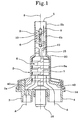
- a mixer particularly adapted to mix viscoelastic substances such as a base and a catalyst being the components of pastes for dental castings has been generally identified with reference numeral 1.
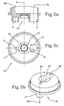
- Said mixer consists of a holding body 2 made of generally transparent plastic material and formed with an outer shell 15 and a base body or plate 14 sealingly coupled to the outer shell.
- the base plate 14 has an inlet 3 designed to receive a first component to be mixed and a second inlet 4 designed to receive the second component to be mixed.
- the two components enter the mixer through the inlets 3, 4 having an axis parallel to the axis 8 of the mixer itself. It is however to be noticed that, alternatively, an inlet with an inclined axis transverse to the symmetry axis 8 can be provided too.
- the base plate 14 and outer shell 15 in cooperation define a pre-chamber 41 for entry of the components, which is capable of deviating the incoming flow from parallel to the axis 8 of the mixer to inclined to the axis itself by means of the inclined surfaces 40 and also radially directed (directions C, D) towards the axis itself through suitable shaped ducts 42, 43.
- the shaped ducts 42, 43 can be inclined in the plane so that the two components are directed to the pre-chamber 41 with inclined directions and opposite ways in the plane (directions C 1 , D 1 ); in this manner an improvement in mixing can be obtained which can be useful in particular as far as rather viscous substances are concerned.
- pre-mixing chamber 41 is not concerned with any fin 12 that could incorporate air bubbles during mixing.
- Fig. 6 contemplates direct entry of the materials into the pre-mixing chamber 41 without any delay being involved, but merely making the two flows run in opposite directions.
- the holding body 2, and in detail the outer shell 15 have a longitudinal extension starting from a first end 2a where the base plate 14 is, as far as an opposite end 2b where an outlet 5 is defined which is adapted to enable the mixed material to go out.
- a mixing chamber 6 defined within the holding body 2 is a mixing chamber 6 in which the two components introduced through the inlets 3, 4 are intimately mixed until the desired homogeneity, being then discharged through the outlet 5.
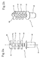
- a dynamic-mixing element 7 a portion 7a of which, made up of the central core 13 and a predetermined number of fins 12 radially emerging therefrom, is positioned movable in rotation around its longitudinal extension axis 8 inside the mixing chamber 6.
- the dynamic-mixing element 7 is provided with a shaped lower attachment 16 designed to be engaged by actuating means (a suitable rotating shaft, for example) that can set it in rotation.
- actuating means a suitable rotating shaft, for example
- This actuating means is not shown or further described as it is of a known type presently on the market.
- the dynamic-mixing element 7 takes up a first region 6a of the mixing chamber 6 generally having a cylindrical conformation with a constant passage section.
- the strictly cylindrical shape of the mixing chamber section however is not binding, but a section having a portion becoming larger or narrower towards the outlet can be also conceived.
- the fins 12 preferably placed at different heights along the extension axis 8 of the mixing element and in a suitable number for each level (in the embodiment shown four fins spaced apart through 90° for each of the four levels), extend from the central core 13 as far as the inner surface of the first region 6a of the mixing chamber so that substantially the whole section is concerned therewith.
- the fins of the rotating shaft are differentiated as follows; a first series has a slender shape, while the end fins 21 are larger and at the upper part thereof have scrapers 22 that nearly touch the inner walls of the tapering portion 20.
- the static-mixing structure 9 is placed immediately downstream of the dynamic-mixing element 7 and exactly terminates at the outlet 5.
- Said structure 9 is rigidly secured to the holding body and in particular to a second region 6b of the mixing chamber 6.
- the second region 6b has an average passage section smaller than the average passage section of the first region 6a.
- the second region 6b too will be of cylindrical conformation and will have a constant passage section.
- static elements 10 of structure 9 define fixed paths for the material flowing through the mixer. These paths are directed transversely of the extension axis 8 of structure 9.
- the elements 10 of the static-mixing structure 9 comprise an Archimedean screw portion in which the surfaces force the material passing therethrough to spin around the mixer axis 8.
- a mixer can be manufactured which has one to four of said shaped surfaces 10.
- Each of the two components is forced by a dispensing machine to enter the mixer under pressure, through the first and second inlets 3, 4 having differentiated passage sections so as to obtain the desired volume ratios between the two products at the entry.
- the base and catalyst are submitted to a first mixing step within the first three fourths of chamber 6, said first mixing step being carried out by the dynamic-mixing element rotating around its axis 8.
- the remaining fourth before entering the static mixer, due to the shape of the last mixing fins 21 and the flow resistance caused by the static element, mixing has a further improvement.
- the material moves forward from the inlets 3, 4 as far as the outlet 5 due to pressure of the incoming material generated by the dispensing machine.
- the material after being mixed in chamber 6a by the dynamic mixer 7, is forced to pass through the second region 6b of the mixing chamber where the static-mixing structure 9 described above is located, which structure induces a third additional mixing operation. Then the material comes out of the outlet 5 so that it can be used.
- the invention achieves important advantages.
- the static portion of the mixer slows down the overall feeding speed of the material that therefore is obliged to remain inside the dynamic-mixing region longer.
- the dynamic-mixing element 7 can ensure better homogenisation of the materials without too long lengths and/or too many fins being required.
- the static mixer is able to carry out an additional mixing operation that further improves the properties of the outgoing material. Therefore, due to the presence of this static-mixing structure 9, the mixer can also operate with substances of different viscosity and obtain a good mixing degree in all cases.
- the end obstruction does not reduce the flow rate if suitable expedients to improve the flow in the other mixer sections are adopted.
- the static element introduces an obstruction that, if suitably studied, enables mixing of the dynamic mixer to be improved and optimisation of the mixing operation to be carried out in the final portion of the mixer itself.
Abstract
Description
- The present invention relates to a mixer and in more detail to a mixer that is simultaneously dynamic and static and is suitable for mixing viscoelastic two-component materials for dental castings.
- It is known that there are presently on the market and are widely spread, devices that are designed to enable dispensing and mixing of two-component materials suitable for castings of the dental arches of a patient.
- In particular, the two constituent materials (base and catalyst) are held in separate containers such as two cylindrical elements of plastic material, for example.
- The containers are compatible with a machine enabling suitable dispensing of the materials by acting on pistons, placed at the inside of the containers themselves, by compression.
- The mixer is connected to the openings of the containers by means of two inlets formed thereon and the shape of which matches that of the respective openings of said containers, and is also provided with a dispensing duct from which the mixed material is discharged for subsequent uses.
- In particular, the mixer consists of a completely hollow body made of plastic material which at an end thereof has said inlets for admission of the base and the catalyst contained in the cylinders.
- Inside the mixer there is a mixing chamber in which a rotating element is housed which is provided with suitable fins to enable optimal homogenisation of the base and catalyst.
- In particular, the rotating element has an actuating shaft directly connected to the dispensing machine in such a manner that the machine itself can simultaneously urge the materials to the mixer's inlets in the desired amounts and volume ratios and can then drive in rotation the rotating element provided with fins.
- The rotation speed of the fins as well as pressure imposed to the materials, and therefore the feeding speed, are such studied that an optimal base-catalyst blend is ensured, which blend therefore comes out of the dispensing outlet in a homogeneous manner.
- The prior art briefly described above is illustrated for example in document
EP 1274501 B1 orEP 1368113 B1 in the name of 3M ESPE or in the documentEP 1 640 060 . - The second document mentioned above discloses a dynamic mixer suitable for mixing particularly viscous substances involving use of paths of travel expressly studied for the materials entering the mixing chamber in order to avoid mutual contamination and improve the subsequent mixing. In addition it is important to notice that, when known dynamic mixers are designed to work with particularly viscous materials, the outlet section is increased so as to reduce the flow resistance.
- In addition, it is known from document
EP 0603492 A1 a device for mixing and distributing materials such as adhesives or sealing agents in which a first "static" component is provided, and in which each of the material components is introduced in a separate condition and distributed, being still kept separate from the other component, at a plurality of points for entry into the true dynamic mixer. - From the inlet region of the dynamic mixer on, the materials start being mixed together by an Archimedean screw driven in rotation around its axis.
- Document
EP 1029585 A1 , on the contrary, shows a general configuration of a mixing device adapted to be alternately used with a static-mixing screw, therefore defining a "static mixer", or with a dynamic rotor within the mixing chamber so as to define a "dynamic mixer". - It is also known, from the document
US 3208958 , a method and an apparatus for producing plastic foam in which two kind of mixers are used. In particular, it is provided a dynamic mixer for mixing and making homogeneous the components of the plastic introduced within the apparatus and a grid arranged downstream the dynamic mixer, for producing an homogeneous foam.<page 3bis> - As clearly described in the text, the two solutions are to be used alternately and cannot be combined together.
- Although the devices briefly described above are presently widespread on the market in a plurality of different versions, the same however have some limits and/or operating drawbacks.
- It is in particular to be noted that the dynamic mixers presently known do not always allow optimal mixing of the base and catalyst.
- In fact, if the material viscosity, rotational speed of the dynamic element and feeding speed of the material itself within the mixer are not optimised, there is a risk of the material coming out in a non-homogeneously mixed manner thus giving rise, as a result, to subsequent problems during manufacture of the casting of the dental arch.
- It is apparent that, once the mixer has been optimised, a change in the viscosity parameters necessarily involves bad mixing of the components and an important reduction in the flow rates if particularly viscous products are used.
- Another negative aspect encountered above all with the most viscous products is creation of air bubbles within the mixed mass, which air bubbles result from an incorrect inner geometry.
- In addition, the dynamic mixer enables a rather quick passage of the components through the mixing chamber and consequently, in order to obtain the appropriate mixing degree, rather long dynamic mixers are to be made or at all events mixers having a minimum number of mixing fins.
- Finally, the sizes of the mixing chamber adversely affect the amount of material remaining within the mixer after use, which material is therefore wasted.
- Accordingly, the present invention aims at substantially solving all the above mentioned drawbacks.
- It is a first object of the invention to manufacture a mixer for viscoelastic materials to be used in the dental sector, which enables a homogeneous and optimal mixing of base and catalyst.
- It is then an aim of the invention to avoid formation of bubbles or other mixing faults inside the mixing chamber and therefore in the discharged material.
- A further aim of the invention is to manufacture a mixer enabling satisfactory flow rates to be obtained even with an important increase in the viscosity of the products.
- Furthermore, it is necessary that, even when very different viscosity and consistency levels are concerned, the homogeneity of the outgoing product should be always ensured.
- Auxiliary objects of the invention involve reduction in the length of the dynamic rotor and/or the number of fins used, without on the other hand adversely affecting the mixer performance.
- It is a further auxiliary object to reduce the residual material inside the mixer at the end of the mixer use, thereby reducing wastes.
- The invention also aims at achieving lower production costs while at the same time manufacturing a mixer which is compatible with the containers of the materials of the dispensing devices presently on the market.
- The foregoing and further aims that will become more apparent in the course of the present description are substantially achieved by a mixer in accordance with the features recited in the appended claims.
- Further features and advantages will be best understood from the detailed description of a preferred but not exclusive embodiment of a specific mixer for viscoelastic substances such as components of pastes for dental castings in accordance with the present invention.
- This description will be set out hereinafter with reference to the accompanying drawings, given by way of non-limiting example, in which:
-
Fig. 1 is a longitudinal section of a mixer in accordance with the present invention; -
Figs. 2a and 2b show the dynamic rotor adopted in the device of the invention; -
Figs. 3a, 3b and 3c show the base body of the mixer seen inFig. 1 ; -
Figs. 4a and 4b show the outer shell of the mixer seen inFig. 1 ; -
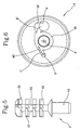
Fig. 5 shows an alternative embodiment of a dynamic mixer in accordance with the invention; and -
Fig. 6 shows an alternative embodiment of the base body of the mixer. - With reference to the drawings a mixer particularly adapted to mix viscoelastic substances such as a base and a catalyst being the components of pastes for dental castings has been generally identified with reference numeral 1.
- Said mixer consists of a
holding body 2 made of generally transparent plastic material and formed with anouter shell 15 and a base body orplate 14 sealingly coupled to the outer shell. - As can be noticed, the
base plate 14 has aninlet 3 designed to receive a first component to be mixed and asecond inlet 4 designed to receive the second component to be mixed. - In the embodiment shown the two components enter the mixer through the
inlets axis 8 of the mixer itself. It is however to be noticed that, alternatively, an inlet with an inclined axis transverse to thesymmetry axis 8 can be provided too. - As can be viewed from
Fig. 1 , the flow of the components is then submitted to a deviation forcing them to enter the mixing chamber with a direction transverse to therotation axis 8. This deviation is in particular caused by the presence of inclinedlower surfaces 40 of theouter shell 15. - Still from the point of view of the entry directions and looking at
Figs. 3b and 3c , it is possible to see that the incoming substances are directed perpendicular to theaxis 8 of the mixer in a horizontal plane (directions C, D inFig. 3c ). - In detail, the
base plate 14 andouter shell 15 in cooperation define a pre-chamber 41 for entry of the components, which is capable of deviating the incoming flow from parallel to theaxis 8 of the mixer to inclined to the axis itself by means of theinclined surfaces 40 and also radially directed (directions C, D) towards the axis itself through suitableshaped ducts - Alternatively (
Fig. 6 ), theshaped ducts - It is finally to be noted that the
pre-mixing chamber 41 is not concerned with anyfin 12 that could incorporate air bubbles during mixing. - At all events, also the embodiment shown in
Fig. 6 contemplates direct entry of the materials into thepre-mixing chamber 41 without any delay being involved, but merely making the two flows run in opposite directions. - In this manner better mixing can be ensured under some situations because the materials enter the mixing chamber with optimal flow inclinations and velocities, that are not necessarily parallel to
axis 8. - The
holding body 2, and in detail theouter shell 15 have a longitudinal extension starting from afirst end 2a where thebase plate 14 is, as far as anopposite end 2b where anoutlet 5 is defined which is adapted to enable the mixed material to go out. - Defined within the
holding body 2 is amixing chamber 6 in which the two components introduced through theinlets outlet 5. - It is possible to see the presence of a dynamic-mixing
element 7 aportion 7a of which, made up of thecentral core 13 and a predetermined number offins 12 radially emerging therefrom, is positioned movable in rotation around itslongitudinal extension axis 8 inside themixing chamber 6. - For the purpose, the dynamic-mixing
element 7 is provided with a shapedlower attachment 16 designed to be engaged by actuating means (a suitable rotating shaft, for example) that can set it in rotation. This actuating means is not shown or further described as it is of a known type presently on the market. - In detail the dynamic-mixing
element 7 takes up afirst region 6a of the mixingchamber 6 generally having a cylindrical conformation with a constant passage section. - The strictly cylindrical shape of the mixing chamber section however is not binding, but a section having a portion becoming larger or narrower towards the outlet can be also conceived.
- In addition, in the embodiment shown there is the presence of a tapering portion 20 (of frustoconical shape) connecting the
first region 6a to thesecond region 6b of the mixingchamber 6. - Within the
first region 6a thefins 12 preferably placed at different heights along theextension axis 8 of the mixing element and in a suitable number for each level (in the embodiment shown four fins spaced apart through 90° for each of the four levels), extend from thecentral core 13 as far as the inner surface of thefirst region 6a of the mixing chamber so that substantially the whole section is concerned therewith. - In particular, the fins of the rotating shaft are differentiated as follows; a first series has a slender shape, while the
end fins 21 are larger and at the upper part thereof havescrapers 22 that nearly touch the inner walls of the taperingportion 20. - Alternatively, adoption of a frustoconical
central core 13 becoming larger from the base to the outlet (Fig. 5 ) can be provided. This involves a further narrowing of the free passage section for the material flowing therethrough. Obviously a frustoconicalcentral core 13 becoming narrower towards theoutlet 5 is also possible. - As shown in the accompanying drawings, downstream of the dynamic-mixing
element 7 along the feeding direction A of the material there is a further mixing structure of thestatic type 9 comprising a plurality ofshaped elements 10 adapted to enable a further subsequent mixing of the materials before they come out of the mixer. - In particular, the static-mixing
structure 9 is placed immediately downstream of the dynamic-mixingelement 7 and exactly terminates at theoutlet 5. - Said
structure 9 is rigidly secured to the holding body and in particular to asecond region 6b of the mixingchamber 6. - It is to be pointed out that the
second region 6b has an average passage section smaller than the average passage section of thefirst region 6a. Generally, thesecond region 6b too will be of cylindrical conformation and will have a constant passage section. - It is also to be pointed out that the
static elements 10 ofstructure 9 define fixed paths for the material flowing through the mixer. These paths are directed transversely of theextension axis 8 ofstructure 9. - In addition, due to passage of said material through such shaped elements in succession, the material is forced to take directions transverse to each other along the feeding travel.
- From a geometric point of view, the
elements 10 of the static-mixingstructure 9 comprise an Archimedean screw portion in which the surfaces force the material passing therethrough to spin around themixer axis 8. - If there is more than one Archimedean screw portion, they will be angularly offset through 90°.
- Obviously, the number of these elements can be stated depending on the material viscosity, the necessary mixing degree to be obtained, the flow resistance generated by this static mixer and all the other design specifications affecting the choice.
- For instance, a mixer can be manufactured which has one to four of said shaped surfaces 10.
- After the above description, operation of the mixer in accordance with the invention is as follows.
- Each of the two components is forced by a dispensing machine to enter the mixer under pressure, through the first and
second inlets chamber 6, said first mixing step being carried out by the dynamic-mixing element rotating around itsaxis 8. In the remaining fourth, before entering the static mixer, due to the shape of thelast mixing fins 21 and the flow resistance caused by the static element, mixing has a further improvement. - The material moves forward from the
inlets outlet 5 due to pressure of the incoming material generated by the dispensing machine. - The material, after being mixed in
chamber 6a by thedynamic mixer 7, is forced to pass through thesecond region 6b of the mixing chamber where the static-mixingstructure 9 described above is located, which structure induces a third additional mixing operation. Then the material comes out of theoutlet 5 so that it can be used. - The invention achieves important advantages.
- It is to be pointed out first of all that adoption of a mixer consisting of a first dynamic portion and a second static portion improves homogeneity of the outgoing material.
- In fact, the static portion of the mixer slows down the overall feeding speed of the material that therefore is obliged to remain inside the dynamic-mixing region longer.
- Due to the above, the dynamic-mixing
element 7 can ensure better homogenisation of the materials without too long lengths and/or too many fins being required. - Besides being a region acting as a "plug", i.e. a region enabling slowing down of the material speed, the static mixer is able to carry out an additional mixing operation that further improves the properties of the outgoing material. Therefore, due to the presence of this static-mixing
structure 9, the mixer can also operate with substances of different viscosity and obtain a good mixing degree in all cases. - In addition, in contrast to common beliefs, the end obstruction does not reduce the flow rate if suitable expedients to improve the flow in the other mixer sections are adopted.
- The static element introduces an obstruction that, if suitably studied, enables mixing of the dynamic mixer to be improved and optimisation of the mixing operation to be carried out in the final portion of the mixer itself.
- Finally, due to the presence of a smaller number of fins of slenderer geometry, heating of the material passing through the mixer is reduced and furthermore, being the mixing chamber of smaller volume, material wastes are reduced too.
Claims (13)
- A mixers for viscoelastic two-component materials for dental castings, comprising:- a holding body (2) which at one end (2a) has at least one inlet (3) for a first component to be mixed and at least one inlet (4) for a second component to be mixed, the holding body (2) further having an outlet (5) disposed to an opposite end (2b) relative to the inlets (3, 4) and in fluid communication with them, the outlet (5) being adapted to enable discharge of the mixed substance, the holding body (2) defining a mixing chamber (6) at the inside thereof;- a dynamic-mixing element (7) having at least one portion (7a) placed inside the mixing chamber (6) and movable in rotation around its longitudinal extension axis (8) to enable mixing of the two components,characterised in that downstream of the dynamic-mixing element (7) along a material feeding direction (A), there is a static-mixing structure (9) comprising a predetermined number of shaped elements (10) adapted to enable further mixing of the materials before discharge from the mixer.
- A mixer as claimed in claim 1, characterised in that the mixing chamber (6) comprises a first region (6a) adapted to contain the dynamic-mixing element (7) and to allow rotation thereof, and a second region (6b) adapted to contain the static-mixing structure (9), the first region (6a) having an average passage section wider than the average passage section of the second region (6b).
- A mixer as claimed in claim 2, characterised in that the second region (6b) is of cylindrical conformation and has a constant passage section, preferably the first region (6a) too being of cylindrical conformation and having a constant passage section, the two regions (6a, 6b) being mutually connected by a tapering portion (20).
- A mixer as claimed in anyone of the preceding claims, characterised in that the static-mixing structure (9) is rigidly secured to the holding body intercepting the whole passage region of the materials.
- A mixer as claimed in anyone of the preceding claims, characterised in that the shaped elements (10) of the static-mixing structure (9) define fixed paths for the material that are directed transversely of the extension axis (8) of the structure (9), said fixed paths in turn defining mutually transverse directions for the material flowing along the feeding travel of the material itself.
- A mixer as claimed in anyone of the preceding claims, characterised in that the static-mixing structure (9) is placed downstream of the dynamic-mixing element and terminates at the outlet (5).
- A mixer as claimed in anyone of the preceding claims, characterised in that the holding body (2) defines a pre-chamber (41) capable of deviating the flow of the incoming materials from parallel to the axis (8) to inclined through inclined surfaces (40).
- A mixer as claimed in claim 7, characterised in that the pre-chamber (41) has shaped ducts (42, 43) to force the two components to the entry according to opposite directions and ways.
- A mixer as claimed in anyone of the preceding claims, characterised in that the dynamic-mixing element (7) comprises a predetermined number of fins (12) radially emerging from a central core (13), the fins (12) being preferably placed to different heights along the extension axis (8) of the mixing element.
- A mixer as claimed in anyone of the preceding claims, characterised in that the dynamic-mixing element (7) further comprises end fins (21) radially emerging from a central core (13), said end fins (21) having scrapers (22) at their upper part which substantially conform in shape to the inner walls of the tapering portion (20).
- A mixer as claimed in anyone of the preceding claims, characterised in that the dynamic-mixing element (7) comprises a central core (13) of frustoconical conformation preferably having a section becoming larger towards the mixer's outlet (5).
- A mixer as claimed in anyone of the preceding claims, characterised in that the holding body (2) comprises an outer shell (15) and a base plate (14) sealingly coupled to the outer shell (15), the base plate (2) being provided with said inlets (3, 4), which inlets (3, 4) have different entrance sections to enable entry of said first and second components to predetermined volume ratios.
- A process for mixing viscoelastic two-component materials for dental castings, comprising the following steps:- introducing the first and second components to be mixed into a mixing chamber (6) through two inlets (3, 4);- carrying out a first mixing operation through a dynamic-mixing element (7) set in rotation around its axis;- carrying out a subsequent second mixing operation through a static-mixing structure (9) comprising a predetermined number of shaped elements (10) adapted to promote further mixing of the materials before discharge from the mixer; and- discharging the homogeneously mixed material from an outlet (5) disposed at an opposite end (2b) relative to the inlets (3, 4).
Priority Applications (4)
| Application Number | Priority Date | Filing Date | Title |
|---|---|---|---|
| AT06425594T ATE395129T1 (en) | 2006-08-21 | 2006-08-21 | DEVICE AND METHOD FOR MIXING A MULTI-COMPONENT MASS FOR DENTAL CAST WORKPIECES |
| DE602006001206T DE602006001206D1 (en) | 2006-08-21 | 2006-08-21 | Apparatus and method for mixing a multicomponent mass for dental castings |
| EP06425594A EP1892033B1 (en) | 2006-08-21 | 2006-08-21 | Apparatus and method for mixing a multi-component substance for dental castings |
| ES06425594T ES2306411T3 (en) | 2006-08-21 | 2006-08-21 | APPARATUS AND PROCEDURE FOR MIXING A MULTI-COMPONENT SUBSTANCE FOR DENTAL MOLDINGS. |
Applications Claiming Priority (1)
| Application Number | Priority Date | Filing Date | Title |
|---|---|---|---|
| EP06425594A EP1892033B1 (en) | 2006-08-21 | 2006-08-21 | Apparatus and method for mixing a multi-component substance for dental castings |
Publications (2)
| Publication Number | Publication Date |
|---|---|
| EP1892033A1 EP1892033A1 (en) | 2008-02-27 |
| EP1892033B1 true EP1892033B1 (en) | 2008-05-14 |
Family
ID=37649297
Family Applications (1)
| Application Number | Title | Priority Date | Filing Date |
|---|---|---|---|
| EP06425594A Active EP1892033B1 (en) | 2006-08-21 | 2006-08-21 | Apparatus and method for mixing a multi-component substance for dental castings |
Country Status (4)
| Country | Link |
|---|---|
| EP (1) | EP1892033B1 (en) |
| AT (1) | ATE395129T1 (en) |
| DE (1) | DE602006001206D1 (en) |
| ES (1) | ES2306411T3 (en) |
Cited By (1)
| Publication number | Priority date | Publication date | Assignee | Title |
|---|---|---|---|---|
| WO2013026722A1 (en) | 2011-08-24 | 2013-02-28 | Kettenbach Gmbh & Co. Kg | Mixer |
Families Citing this family (8)
| Publication number | Priority date | Publication date | Assignee | Title |
|---|---|---|---|---|
| WO2009071318A2 (en) * | 2007-12-07 | 2009-06-11 | Sg-Isy Gmbh & Co. Kg | Mixing device, system for mixing components, squeeze-out device for film bags, mixing attachment for high-pressure mixing and/or dosing systems having a mixing device, and joint connector for hoses and/or pipes |
| US8197122B2 (en) * | 2008-04-24 | 2012-06-12 | Tyco Healthcare Group Lp | Dynamic mixing applicator |
| EP2399666B1 (en) | 2010-06-22 | 2013-02-20 | 3M Innovative Properties Company | Mixer for preparing a dental material, and system comprising the same |
| RU2586692C1 (en) * | 2014-12-31 | 2016-06-10 | Федеральное государственное бюджетное образовательное учреждение высшего профессионального образования "Российский химико-технологический университет имени Д.И. Менделеева (РХТУ им. Д.И. Менделеева)" | Mixer-aerator for liquid-phase streams |
| DE102015105186A1 (en) | 2015-04-02 | 2016-10-06 | Rublic + Canzler GmbH | Discharge device for pasty masses |
| JP6994112B2 (en) | 2017-07-28 | 2022-01-14 | 3エルエムエーデー ゲゼルシャフト ミット ベシュレンクテル ハフツング | mixer |
| DE102017117199A1 (en) | 2017-07-28 | 2019-01-31 | 3lmed GmbH | Mixer with compensation channel and / or stowage chamber |
| EP3823744A1 (en) * | 2018-07-18 | 2021-05-26 | Nordson Corporation | Adapter with integral mixer element |
Family Cites Families (7)
| Publication number | Priority date | Publication date | Assignee | Title |
|---|---|---|---|---|
| US3208958A (en) * | 1963-03-04 | 1965-09-28 | Pacific Vegets Le Oil Corp | Method and apparatus for producing plastic foam |
| JPS6052926B2 (en) * | 1981-05-18 | 1985-11-22 | 積水化成品工業株式会社 | Thermoplastic resin foam manufacturing method and device |
| JPS58122029A (en) * | 1981-09-14 | 1983-07-20 | Mitsuo Mochizuki | Liquefying device of fine granular powder |
| FR2548043A1 (en) * | 1983-06-14 | 1985-01-04 | Saint Gobain Vitrage | METHOD AND DEVICE FOR CASTING MANUFACTURE OF TRANSPARENT OPTICALLY HOMOGENEOUS LAYER FROM COMPONENT MIXTURE |
| US5149720A (en) * | 1991-08-12 | 1992-09-22 | The Procter & Gamble Company | Process for preparing emulsions that are polymerizable to absorbent foam materials |
| DE4235736C1 (en) * | 1992-10-23 | 1994-03-24 | Bergmann Franz Josef | Device for mixing and distributing paste pulp - comprises combination of static mixer with channels for the breakdown and pre-distribution of the pulp into a number of thin strands |
| EP1640060A1 (en) * | 2004-09-22 | 2006-03-29 | 3M Espe Ag | Mixer for multi-component pastes, kit, and method of mixing paste components |
-
2006
- 2006-08-21 EP EP06425594A patent/EP1892033B1/en active Active
- 2006-08-21 ES ES06425594T patent/ES2306411T3/en active Active
- 2006-08-21 AT AT06425594T patent/ATE395129T1/en not_active IP Right Cessation
- 2006-08-21 DE DE602006001206T patent/DE602006001206D1/en active Active
Cited By (1)
| Publication number | Priority date | Publication date | Assignee | Title |
|---|---|---|---|---|
| WO2013026722A1 (en) | 2011-08-24 | 2013-02-28 | Kettenbach Gmbh & Co. Kg | Mixer |
Also Published As
| Publication number | Publication date |
|---|---|
| DE602006001206D1 (en) | 2008-06-26 |
| ATE395129T1 (en) | 2008-05-15 |
| ES2306411T3 (en) | 2008-11-01 |
| EP1892033A1 (en) | 2008-02-27 |
Similar Documents
| Publication | Publication Date | Title |
|---|---|---|
| US7731413B2 (en) | Mixer for multi-components substance for dental casting | |
| EP1892033B1 (en) | Apparatus and method for mixing a multi-component substance for dental castings | |
| AU2012222534B2 (en) | Dynamic mixer | |
| US6540395B2 (en) | Dynamic mixer for dental impression compounds | |
| CN101282781B (en) | Dynamic mixer | |
| JP6077469B2 (en) | Dynamic mixer | |
| US7771110B2 (en) | Twisted static paste mixer with a dynamic premixing chamber | |
| JP2000117080A (en) | Mixer for multicomponent paste | |
| US8123394B2 (en) | Mixer for liquid colorants and method for mixing liquid colorants | |
| KR20080046280A (en) | Apparatus and method for mixing liquid colour and method for colouring plastics with liquid colour | |
| CN102946985B (en) | For the preparation of blender and the system comprising described blender of dental material | |
| JP5382287B2 (en) | Mixer | |
| US20080264809A1 (en) | Method for the Production of Dental Moulding Materials and Device Therefor | |
| JP4413561B2 (en) | Dental impression mixing mixer | |
| BRPI0801637B1 (en) | MIXER-MIXER | |
| RU2455957C2 (en) | Mixer | |
| KR101713870B1 (en) | Dynamic mixer and use thereof | |
| CN218358570U (en) | Sanitary high-viscosity small-proportion high-efficiency dynamic mixer | |
| CN212549345U (en) | Novel dual-mode disposable tooth impression material mixer | |
| CN219765086U (en) | Dynamic glue mixing stirrer | |
| CN211514342U (en) | Continuous mixer | |
| MX2008004420A (en) | Dynamic mixer |
Legal Events
| Date | Code | Title | Description |
|---|---|---|---|
| GRAP | Despatch of communication of intention to grant a patent |
Free format text: ORIGINAL CODE: EPIDOSNIGR1 |
|
| PUAI | Public reference made under article 153(3) epc to a published international application that has entered the european phase |
Free format text: ORIGINAL CODE: 0009012 |
|
| 17P | Request for examination filed |
Effective date: 20070213 |
|
| AK | Designated contracting states |
Kind code of ref document: A1 Designated state(s): AT BE BG CH CY CZ DE DK EE ES FI FR GB GR HU IE IS IT LI LT LU LV MC NL PL PT RO SE SI SK TR |
|
| AX | Request for extension of the european patent |
Extension state: AL BA HR MK YU |
|
| GRAS | Grant fee paid |
Free format text: ORIGINAL CODE: EPIDOSNIGR3 |
|
| GRAA | (expected) grant |
Free format text: ORIGINAL CODE: 0009210 |
|
| AK | Designated contracting states |
Kind code of ref document: B1 Designated state(s): AT BE BG CH CY CZ DE DK EE ES FI FR GB GR HU IE IS IT LI LT LU LV MC NL PL PT RO SE SI SK TR |
|
| AX | Request for extension of the european patent |
Extension state: AL BA HR MK RS |
|
| REG | Reference to a national code |
Ref country code: GB Ref legal event code: FG4D |
|
| REG | Reference to a national code |
Ref country code: CH Ref legal event code: EP |
|
| REG | Reference to a national code |
Ref country code: IE Ref legal event code: FG4D Free format text: LANGUAGE OF EP DOCUMENT: FRENCH |
|
| REF | Corresponds to: |
Ref document number: 602006001206 Country of ref document: DE Date of ref document: 20080626 Kind code of ref document: P |
|
| REG | Reference to a national code |
Ref country code: CH Ref legal event code: NV Representative=s name: BUGNION S.A. |
|
| PG25 | Lapsed in a contracting state [announced via postgrant information from national office to epo] |
Ref country code: SI Free format text: LAPSE BECAUSE OF FAILURE TO SUBMIT A TRANSLATION OF THE DESCRIPTION OR TO PAY THE FEE WITHIN THE PRESCRIBED TIME-LIMIT Effective date: 20080514 |
|
| PG25 | Lapsed in a contracting state [announced via postgrant information from national office to epo] |
Ref country code: FI Free format text: LAPSE BECAUSE OF FAILURE TO SUBMIT A TRANSLATION OF THE DESCRIPTION OR TO PAY THE FEE WITHIN THE PRESCRIBED TIME-LIMIT Effective date: 20080514 |
|
| REG | Reference to a national code |
Ref country code: ES Ref legal event code: FG2A Ref document number: 2306411 Country of ref document: ES Kind code of ref document: T3 |
|
| NLV1 | Nl: lapsed or annulled due to failure to fulfill the requirements of art. 29p and 29m of the patents act | ||
| AKX | Designation fees paid |
Designated state(s): AT BE BG CH CY CZ DE DK EE ES FI FR GB GR HU IE IS IT LI LT LU LV MC NL PL PT RO SE SI SK TR |
|
| AXX | Extension fees paid |
Extension state: RS Payment date: 20080303 Extension state: HR Payment date: 20080303 Extension state: MK Payment date: 20080303 Extension state: BA Payment date: 20080303 Extension state: AL Payment date: 20080303 |
|
| PG25 | Lapsed in a contracting state [announced via postgrant information from national office to epo] |
Ref country code: AT Free format text: LAPSE BECAUSE OF FAILURE TO SUBMIT A TRANSLATION OF THE DESCRIPTION OR TO PAY THE FEE WITHIN THE PRESCRIBED TIME-LIMIT Effective date: 20080514 Ref country code: PL Free format text: LAPSE BECAUSE OF FAILURE TO SUBMIT A TRANSLATION OF THE DESCRIPTION OR TO PAY THE FEE WITHIN THE PRESCRIBED TIME-LIMIT Effective date: 20080514 Ref country code: NL Free format text: LAPSE BECAUSE OF FAILURE TO SUBMIT A TRANSLATION OF THE DESCRIPTION OR TO PAY THE FEE WITHIN THE PRESCRIBED TIME-LIMIT Effective date: 20080514 Ref country code: LV Free format text: LAPSE BECAUSE OF FAILURE TO SUBMIT A TRANSLATION OF THE DESCRIPTION OR TO PAY THE FEE WITHIN THE PRESCRIBED TIME-LIMIT Effective date: 20080514 |
|
| PG25 | Lapsed in a contracting state [announced via postgrant information from national office to epo] |
Ref country code: IS Free format text: LAPSE BECAUSE OF FAILURE TO SUBMIT A TRANSLATION OF THE DESCRIPTION OR TO PAY THE FEE WITHIN THE PRESCRIBED TIME-LIMIT Effective date: 20080914 |
|
| PG25 | Lapsed in a contracting state [announced via postgrant information from national office to epo] |
Ref country code: LT Free format text: LAPSE BECAUSE OF FAILURE TO SUBMIT A TRANSLATION OF THE DESCRIPTION OR TO PAY THE FEE WITHIN THE PRESCRIBED TIME-LIMIT Effective date: 20080514 Ref country code: SE Free format text: LAPSE BECAUSE OF FAILURE TO SUBMIT A TRANSLATION OF THE DESCRIPTION OR TO PAY THE FEE WITHIN THE PRESCRIBED TIME-LIMIT Effective date: 20080814 Ref country code: DK Free format text: LAPSE BECAUSE OF FAILURE TO SUBMIT A TRANSLATION OF THE DESCRIPTION OR TO PAY THE FEE WITHIN THE PRESCRIBED TIME-LIMIT Effective date: 20080514 Ref country code: CZ Free format text: LAPSE BECAUSE OF FAILURE TO SUBMIT A TRANSLATION OF THE DESCRIPTION OR TO PAY THE FEE WITHIN THE PRESCRIBED TIME-LIMIT Effective date: 20080514 |
|
| PG25 | Lapsed in a contracting state [announced via postgrant information from national office to epo] |
Ref country code: PT Free format text: LAPSE BECAUSE OF FAILURE TO SUBMIT A TRANSLATION OF THE DESCRIPTION OR TO PAY THE FEE WITHIN THE PRESCRIBED TIME-LIMIT Effective date: 20081014 Ref country code: SK Free format text: LAPSE BECAUSE OF FAILURE TO SUBMIT A TRANSLATION OF THE DESCRIPTION OR TO PAY THE FEE WITHIN THE PRESCRIBED TIME-LIMIT Effective date: 20080514 Ref country code: RO Free format text: LAPSE BECAUSE OF FAILURE TO SUBMIT A TRANSLATION OF THE DESCRIPTION OR TO PAY THE FEE WITHIN THE PRESCRIBED TIME-LIMIT Effective date: 20080514 Ref country code: BE Free format text: LAPSE BECAUSE OF FAILURE TO SUBMIT A TRANSLATION OF THE DESCRIPTION OR TO PAY THE FEE WITHIN THE PRESCRIBED TIME-LIMIT Effective date: 20080514 |
|
| PLBE | No opposition filed within time limit |
Free format text: ORIGINAL CODE: 0009261 |
|
| STAA | Information on the status of an ep patent application or granted ep patent |
Free format text: STATUS: NO OPPOSITION FILED WITHIN TIME LIMIT |
|
| PG25 | Lapsed in a contracting state [announced via postgrant information from national office to epo] |
Ref country code: MC Free format text: LAPSE BECAUSE OF NON-PAYMENT OF DUE FEES Effective date: 20080831 |
|
| 26N | No opposition filed |
Effective date: 20090217 |
|
| PG25 | Lapsed in a contracting state [announced via postgrant information from national office to epo] |
Ref country code: BG Free format text: LAPSE BECAUSE OF FAILURE TO SUBMIT A TRANSLATION OF THE DESCRIPTION OR TO PAY THE FEE WITHIN THE PRESCRIBED TIME-LIMIT Effective date: 20080814 Ref country code: EE Free format text: LAPSE BECAUSE OF FAILURE TO SUBMIT A TRANSLATION OF THE DESCRIPTION OR TO PAY THE FEE WITHIN THE PRESCRIBED TIME-LIMIT Effective date: 20080514 |
|
| REG | Reference to a national code |
Ref country code: IE Ref legal event code: MM4A |
|
| PG25 | Lapsed in a contracting state [announced via postgrant information from national office to epo] |
Ref country code: IE Free format text: LAPSE BECAUSE OF NON-PAYMENT OF DUE FEES Effective date: 20080821 |
|
| PG25 | Lapsed in a contracting state [announced via postgrant information from national office to epo] |
Ref country code: CY Free format text: LAPSE BECAUSE OF FAILURE TO SUBMIT A TRANSLATION OF THE DESCRIPTION OR TO PAY THE FEE WITHIN THE PRESCRIBED TIME-LIMIT Effective date: 20080514 Ref country code: HU Free format text: LAPSE BECAUSE OF FAILURE TO SUBMIT A TRANSLATION OF THE DESCRIPTION OR TO PAY THE FEE WITHIN THE PRESCRIBED TIME-LIMIT Effective date: 20081115 Ref country code: LU Free format text: LAPSE BECAUSE OF NON-PAYMENT OF DUE FEES Effective date: 20080821 |
|
| PG25 | Lapsed in a contracting state [announced via postgrant information from national office to epo] |
Ref country code: TR Free format text: LAPSE BECAUSE OF FAILURE TO SUBMIT A TRANSLATION OF THE DESCRIPTION OR TO PAY THE FEE WITHIN THE PRESCRIBED TIME-LIMIT Effective date: 20080514 |
|
| PG25 | Lapsed in a contracting state [announced via postgrant information from national office to epo] |
Ref country code: GR Free format text: LAPSE BECAUSE OF FAILURE TO SUBMIT A TRANSLATION OF THE DESCRIPTION OR TO PAY THE FEE WITHIN THE PRESCRIBED TIME-LIMIT Effective date: 20080815 |
|
| REG | Reference to a national code |
Ref country code: FR Ref legal event code: PLFP Year of fee payment: 11 |
|
| REG | Reference to a national code |
Ref country code: FR Ref legal event code: PLFP Year of fee payment: 12 |
|
| REG | Reference to a national code |
Ref country code: FR Ref legal event code: PLFP Year of fee payment: 13 |
|
| REG | Reference to a national code |
Ref country code: DE Ref legal event code: R079 Ref document number: 602006001206 Country of ref document: DE Free format text: PREVIOUS MAIN CLASS: B01F0003080000 Ipc: B01F0023400000 |
|
| P01 | Opt-out of the competence of the unified patent court (upc) registered |
Effective date: 20230515 |
|
| PGFP | Annual fee paid to national office [announced via postgrant information from national office to epo] |
Ref country code: IT Payment date: 20230711 Year of fee payment: 18 Ref country code: GB Payment date: 20230629 Year of fee payment: 18 Ref country code: ES Payment date: 20230908 Year of fee payment: 18 Ref country code: CH Payment date: 20230902 Year of fee payment: 18 |
|
| PGFP | Annual fee paid to national office [announced via postgrant information from national office to epo] |
Ref country code: FR Payment date: 20230703 Year of fee payment: 18 Ref country code: DE Payment date: 20230703 Year of fee payment: 18 |