JP2007524003A - Method for treating aluminum in rotary or reflective furnaces - Google Patents
Method for treating aluminum in rotary or reflective furnaces Download PDFInfo
- Publication number
- JP2007524003A JP2007524003A JP2007500266A JP2007500266A JP2007524003A JP 2007524003 A JP2007524003 A JP 2007524003A JP 2007500266 A JP2007500266 A JP 2007500266A JP 2007500266 A JP2007500266 A JP 2007500266A JP 2007524003 A JP2007524003 A JP 2007524003A
- Authority
- JP
- Japan
- Prior art keywords
- aluminum
- furnace
- concentration
- volume
- stage
- Prior art date
- Legal status (The legal status is an assumption and is not a legal conclusion. Google has not performed a legal analysis and makes no representation as to the accuracy of the status listed.)
- Pending
Links
Images

Classifications
-
- F—MECHANICAL ENGINEERING; LIGHTING; HEATING; WEAPONS; BLASTING
- F27—FURNACES; KILNS; OVENS; RETORTS
- F27B—FURNACES, KILNS, OVENS, OR RETORTS IN GENERAL; OPEN SINTERING OR LIKE APPARATUS
- F27B3/00—Hearth-type furnaces, e.g. of reverberatory type; Tank furnaces
- F27B3/10—Details, accessories, or equipment peculiar to hearth-type furnaces
- F27B3/28—Arrangement of controlling, monitoring, alarm or the like devices
-
- C—CHEMISTRY; METALLURGY
- C22—METALLURGY; FERROUS OR NON-FERROUS ALLOYS; TREATMENT OF ALLOYS OR NON-FERROUS METALS
- C22B—PRODUCTION AND REFINING OF METALS; PRETREATMENT OF RAW MATERIALS
- C22B21/00—Obtaining aluminium
- C22B21/0084—Obtaining aluminium melting and handling molten aluminium
- C22B21/0092—Remelting scrap, skimmings or any secondary source aluminium
-
- C—CHEMISTRY; METALLURGY
- C22—METALLURGY; FERROUS OR NON-FERROUS ALLOYS; TREATMENT OF ALLOYS OR NON-FERROUS METALS
- C22B—PRODUCTION AND REFINING OF METALS; PRETREATMENT OF RAW MATERIALS
- C22B21/00—Obtaining aluminium
- C22B21/06—Obtaining aluminium refining
-
- C—CHEMISTRY; METALLURGY
- C22—METALLURGY; FERROUS OR NON-FERROUS ALLOYS; TREATMENT OF ALLOYS OR NON-FERROUS METALS
- C22B—PRODUCTION AND REFINING OF METALS; PRETREATMENT OF RAW MATERIALS
- C22B9/00—General processes of refining or remelting of metals; Apparatus for electroslag or arc remelting of metals
- C22B9/006—General processes of refining or remelting of metals; Apparatus for electroslag or arc remelting of metals with use of an inert protective material including the use of an inert gas
-
- F—MECHANICAL ENGINEERING; LIGHTING; HEATING; WEAPONS; BLASTING
- F27—FURNACES; KILNS; OVENS; RETORTS
- F27D—DETAILS OR ACCESSORIES OF FURNACES, KILNS, OVENS, OR RETORTS, IN SO FAR AS THEY ARE OF KINDS OCCURRING IN MORE THAN ONE KIND OF FURNACE
- F27D19/00—Arrangements of controlling devices
-
- F—MECHANICAL ENGINEERING; LIGHTING; HEATING; WEAPONS; BLASTING
- F27—FURNACES; KILNS; OVENS; RETORTS
- F27D—DETAILS OR ACCESSORIES OF FURNACES, KILNS, OVENS, OR RETORTS, IN SO FAR AS THEY ARE OF KINDS OCCURRING IN MORE THAN ONE KIND OF FURNACE
- F27D19/00—Arrangements of controlling devices
- F27D2019/0006—Monitoring the characteristics (composition, quantities, temperature, pressure) of at least one of the gases of the kiln atmosphere and using it as a controlling value
-
- F—MECHANICAL ENGINEERING; LIGHTING; HEATING; WEAPONS; BLASTING
- F27—FURNACES; KILNS; OVENS; RETORTS
- F27D—DETAILS OR ACCESSORIES OF FURNACES, KILNS, OVENS, OR RETORTS, IN SO FAR AS THEY ARE OF KINDS OCCURRING IN MORE THAN ONE KIND OF FURNACE
- F27D19/00—Arrangements of controlling devices
- F27D2019/0028—Regulation
- F27D2019/0034—Regulation through control of a heating quantity such as fuel, oxidant or intensity of current
-
- Y—GENERAL TAGGING OF NEW TECHNOLOGICAL DEVELOPMENTS; GENERAL TAGGING OF CROSS-SECTIONAL TECHNOLOGIES SPANNING OVER SEVERAL SECTIONS OF THE IPC; TECHNICAL SUBJECTS COVERED BY FORMER USPC CROSS-REFERENCE ART COLLECTIONS [XRACs] AND DIGESTS
- Y02—TECHNOLOGIES OR APPLICATIONS FOR MITIGATION OR ADAPTATION AGAINST CLIMATE CHANGE
- Y02P—CLIMATE CHANGE MITIGATION TECHNOLOGIES IN THE PRODUCTION OR PROCESSING OF GOODS
- Y02P10/00—Technologies related to metal processing
- Y02P10/20—Recycling
Abstract
Description
本発明は、アルミニウム含有物質および必要に応じて1つ以上の塩および/またはスラッジおよび/または再循環ドロスは炉内に導入され、この物質はことによるとスラッジ、特にアルミナを含む、で覆われた溶融アルミニウムを得るように酸化剤および燃料を供給する少なくとも1つのバーナを用いて加熱することによって溶融され、かつ一酸化炭素および/または水素濃度は炉雰囲気または煙道ガスで測定される炉内のアルミニウムの処理方法に関する。 The present invention covers an aluminum-containing material and optionally one or more salts and / or sludge and / or recirculating dross that is introduced into the furnace, this material possibly including sludge, especially alumina. In a furnace which is melted by heating with at least one burner supplying oxidant and fuel to obtain molten aluminum and whose carbon monoxide and / or hydrogen concentration is measured in the furnace atmosphere or flue gas The present invention relates to a method for treating aluminum.
二次アルミニウム溶融の分野において、この操作は回転炉または反射炉でなされる。この溶融処理は連続でもよいが、通常、前記物質は溶融金属が使用の場に注入される前に1つまたはそれ以上の連続的循環で炉に装填される、バッチでなされる。この目的のために、溶融金属は約740℃の温度を有する必要がある。750℃以上で、溶融アルミニウムの酸加速度は顕著にかつ殆ど指数関数的に増加する。 In the field of secondary aluminum melting, this operation is done in a rotary furnace or a reflection furnace. This melting process may be continuous, but usually the material is made in batches where the molten metal is loaded into the furnace in one or more continuous cycles before being injected into the field of use. For this purpose, the molten metal needs to have a temperature of about 740 ° C. Above 750 ° C., the acid acceleration of molten aluminum increases significantly and almost exponentially.
溶融循環の間、物質が固体で大量の熱の吸収をなす初期期間は約660℃でのアルミニウム溶融で素早く識別できる。 During the melting cycle, the initial period during which the material is solid and absorbs a large amount of heat can be quickly identified by melting aluminum at about 660 ° C.
使用される炉の種類に関係なく、スラッジまたは“ドロス”は溶融表面に見出される。識別は、有機物およびより一般的に装填に初期に存在される非金属物質の熱分解によって発生される種々の廃固体有機化合物(ポリ環状芳香族炭化水素、煤等)、酸化物中に封じ込められるアルミニウム酸化物およびアルミニウム、の塩(処理が塩を使用されるなら)の混合物である“黒”ドロスと称される一方と、溶融を目的とする専ら金属合金からなる装填物を清浄に処理する炉内で生産される、アルミニウム酸化物およびアルミニウムを主体として構成される“白”ドロスと称される他方との間で一般的にもたらされる。“黒”ドロスは煙道ガスで未燃焼炭化水素の富化にて蒸発有機化合物(VOC)の大量の放出によって随伴されることを気が付くべきである。 Regardless of the type of furnace used, sludge or “dross” is found on the molten surface. Identification is encapsulated in various waste solid organic compounds (polycyclic aromatic hydrocarbons, soot, etc.), oxides generated by pyrolysis of organic matter and more generally non-metallic materials initially present in the load Cleanly treat a charge consisting of a metal alloy exclusively for melting purposes, referred to as “black” dross, which is a mixture of aluminum oxide and aluminum salts (if the process uses salt) It is generally produced between the other, referred to as “white” dross, composed mainly of aluminum oxide and aluminum, produced in a furnace. It should be noted that “black” dross is accompanied by a large release of vaporized organic compounds (VOC) in the flue gas enrichment of unburned hydrocarbons.
このスラッジまたはドロスは、アルミニウム生産者にとって無視し得ない物質の減量を表し、かつ溶融処理の収益性を向上するために最小に減少すべき“強熱減量”とやはり称される、失われるかまたは酸化された金属のある量を含む。酸化を減少するために、アルミニウム溶融温度を約750℃以下の値に維持することが知られている。しかしながら、この方法は高温個所が局所的酸化に起因して表面に現れることを経験する。 Is this sludge or dross lost, which represents a weight loss of material that is not negligible for aluminum producers and is also referred to as “ignition weight loss” that should be reduced to a minimum to improve the profitability of the melting process? Or contain some amount of oxidized metal. In order to reduce oxidation, it is known to maintain the aluminum melting temperature at a value below about 750 ° C. However, this method experiences that hot spots appear on the surface due to local oxidation.
他の知られた解決は、酸化剤との金属表面の接触を低減することによって酸化を防ぐ。 Other known solutions prevent oxidation by reducing metal surface contact with the oxidant.
したがって、文献JP 58−227706は非鉄金属溶解炉に据え付けられたバーナが消費されずに残っている燃料の一部で、95%と100%の間の範囲にある燃料流速に対する酸化剤の比の値の範囲の亜理論モードで操作することを立証するために煙道ガス中のCOおよびH2量の測定を用いることを提示している。 The document JP 58-227706 is therefore part of the remaining fuel that is not consumed by the burner installed in the non-ferrous metal melting furnace, with the ratio of oxidizer to fuel flow rate in the range between 95% and 100%. It is proposed to use measurements of the amount of CO and H 2 in the flue gas to demonstrate operating in a sub-theoretical mode of value range.
文献EP 962 540は、酸素富化ガスが液状金属と接するバーナの炎上の炉に送られる、炉内金属溶融用燃焼処理を記載している。 Document EP 962 540 describes a combustion process for in-furnace metal melting in which an oxygen-enriched gas is sent to a burner flame furnace in contact with a liquid metal.
亜理論モードで操作する、前記バーナは前記酸素富化ガスと溶融表面の間に障壁を創る還元炎を生成する。 Operating in sub-theoretical mode, the burner produces a reducing flame that creates a barrier between the oxygen-enriched gas and the molten surface.
文献US 5 563 903は、不活性または還元ガスがアルミニウム溶融表面と炉の上部に位置する燃焼ゾーンの間に障壁を創る方法が記載している。 Document US 5 563 903 describes a method in which an inert or reducing gas creates a barrier between the aluminum melting surface and the combustion zone located at the top of the furnace.
文献US 3 759 702は、溶融が溶融されるべき物質の表面上を動くバーナにて、開放空気で初期に生じる方法を記載している。前記バーナ炎は、還元であるので僅かに亜理論である。 Document US 3 759 702 describes a method in which melting occurs initially in open air in a burner that moves over the surface of the material to be melted. The burner flame is slightly sub-theory because it is a reduction.
全てのこれら方法は、不完全な結果をもたらし、溶融の期間中を通して適用され、かつアルミニウム酸化の危険が存在するときのみでない。 All these methods give incomplete results, are applied throughout the period of melting, and not only when there is a risk of aluminum oxidation.
現在、第1段階が“黒”ドロスを生成せず、従って高VOCを放出し、同時に方法の最終段階の間、アルミニウムの酸化を最小にするとしても適用可能であるアルミニウムを処理する方法が必要である。 Currently, there is a need for a method of treating aluminum that does not produce "black" dross in the first stage, and thus releases high VOC, and at the same time is applicable even if aluminum oxidation is minimized during the final stage of the process. It is.
本発明の方法は、提示される問題を解決するために供し、かつアルミニウム酸化物の形成を減少する。 The method of the present invention serves to solve the problems presented and reduces the formation of aluminum oxide.
少なくとも1つのバーナに供給される酸化剤は10体積%を超える酸素、好ましくは21体積%を超える酸素を含み、かつ前記方法は少なくとも1つのバーナに噴射される燃料の流速が雰囲気または煙道ガスで一酸化炭素および/または水素濃度の関数であるか、またはその反対(すなわち、燃料流速が実質的に一定で、かつ酸化剤流速がそれらを以下に設定する限り同じ限界内に含まれるCOおよび/またはH2濃度に依存する)のときに前記酸化剤流速が実質的に一定である、間に前記溶融アルミニウムの酸化を低減する最終段階を含み、一酸化炭素および/または水素濃度は3体積%と15体積%の間(反対に、燃料流速が一定で酸化剤流速がCOおよび/またはH2濃度に依存する可能性を意味する)ことを特徴とする。 The oxidant fed to the at least one burner comprises more than 10% by volume oxygen, preferably more than 21% by volume, and the method has a flow rate of fuel injected into the at least one burner of atmosphere or flue gas Is a function of carbon monoxide and / or hydrogen concentration, or vice versa (i.e., CO and within the same limits as long as the fuel flow rate is substantially constant and the oxidant flow rate is set below) The oxidant flow rate is substantially constant (depending on the H 2 concentration), including a final stage during which the oxidation of the molten aluminum is reduced, with a carbon monoxide and / or hydrogen concentration of 3 volumes % And 15% by volume (conversely, meaning that the fuel flow rate is constant and the oxidant flow rate may depend on CO and / or H 2 concentration).
好ましくは、前記酸化剤は88体積%を超えるO2、好ましくは95体積%を超えるO2を含む。より好ましくは、前記酸化剤は工業的に純粋な酸素である。 Preferably, the oxidizing agent contains more than 88% by volume O 2 , preferably more than 95% by volume O 2 . More preferably, the oxidant is industrially pure oxygen.
前記燃料は、いくつかの炭化水素または軽もしくは重燃料油(前記バーナの適切な燃料油噴射システムで)でもよく、天然ガス、メタン、プロパン等が好ましく用いられる。燃料に対する酸素の容積比は、1と5の間、好ましくは1.5と3の間に維持される。 The fuel may be some hydrocarbon or light or heavy fuel oil (with the appropriate fuel oil injection system of the burner), preferably natural gas, methane, propane, etc. The volume ratio of oxygen to fuel is maintained between 1 and 5, preferably between 1.5 and 3.
本発明の1つの変形によれば、COおよび/またはH2濃度は6体積%と10体積%の間の値でこの酸化限界段階全体を通して本質的に一定に維持される(この最終段階の間、目標値C2はそれゆえこの範囲内の値に設定されることが好ましい)。 According to one variant of the invention, the CO and / or H 2 concentration is kept essentially constant throughout this oxidation limit stage at a value between 6 and 10% by volume (during this final stage). The target value C2 is therefore preferably set to a value within this range).
一般的に、前記酸化限界段階は前記物質に存在される本質的に全ての有機化合物が熱分解により破壊される、ことによると(必要でないが)安定化段階がこれに続く、間のVOC燃焼段階に先行される。 In general, the oxidation limit stage involves essentially all organic compounds present in the material being destroyed by thermal decomposition, possibly followed by a stabilization stage (but not necessary) during VOC combustion. Preceding the stage.
好ましくは、VOC燃焼段階はこの段階の間、燃料の容積流速に対する酸化剤に含まれる酸素の容積流速が以下に定義される閾値S、以下に下がるときに終結する。一般的に、一時的なずれに対処するためにこの炭化水素燃焼段階の条件は炉または煙道ガスで測定されるCOの目標値(C1値〜C2値)を変化させることによって第1段階に入る前に、値R<Sの推移を確認するために更なる期間Δt(当該の炭化水素燃焼段階の5%と20%の間)に維持される(例えば、図2に例示されるようにCO濃度での変化の可能な限りのずれを考慮する)。この期間Δtの段階は、検出段階と同様に以下に参照される。 Preferably, the VOC combustion phase ends during this phase when the volumetric flow rate of oxygen contained in the oxidizer relative to the volumetric flow rate of the fuel falls below a threshold value S defined below. In general, this hydrocarbon combustion stage condition is changed to the first stage by changing the target value of CO (C1 value to C2 value) measured in the furnace or flue gas in order to deal with temporary deviations. Before entering, it is maintained for a further period Δt (between 5% and 20% of the relevant hydrocarbon combustion stage) to confirm the transition of the value R <S (eg as illustrated in FIG. 2). Taking into account possible deviations in changes in CO concentration). The stage of this period Δt is referred to below as well as the detection stage.
本発明の好ましい態様によれば、方法は有機化合物の完全な分解を確認するために意図される一般的に短い検出段階によってできる限り分離される2つの段階(液状アルミニウムが注入される前に何回か繰り返すことができる)を含む。 According to a preferred embodiment of the present invention, the method is generally divided into two stages separated by as much as possible by a generally short detection stage intended to confirm complete decomposition of the organic compound (whatever the liquid aluminum is before being injected). Can be repeated several times).
好ましくは、第1段階の間に炉雰囲気および/または煙道ガスのCO濃度は0.1vol%と5vol%の間(目標値C1)である。下限は、煙道ガス(または雰囲気)が最大1000ppmの酸素を含むように実際のところ決定される。 Preferably, during the first stage, the CO concentration of the furnace atmosphere and / or the flue gas is between 0.1 vol% and 5 vol% (target value C1). The lower limit is actually determined so that the flue gas (or atmosphere) contains up to 1000 ppm oxygen.
一般的に、約0.5vol%のCO値が適切であることがわかった。この第1段階の間に、目標は雰囲気中で最低限のCOを得る、すなわち炉内で非酸化雰囲気を維持する間に0.1vol%と5vol%の間隔にて最低限の値でCO濃度の目標値C1に調節することである。 In general, a CO value of about 0.5 vol% has been found to be appropriate. During this first phase, the goal is to obtain a minimum CO in the atmosphere, i.e. a minimum CO concentration at intervals of 0.1 vol% and 5 vol% while maintaining a non-oxidizing atmosphere in the furnace. To the target value C1.
制御の欠如において、COおよび/またはH2濃度は、上に選択された目標値C1以上に上昇する。反対に、最終段階の間に、H2および/またはCO濃度(本発明が適用されないならば)は目標値C1より低くなり、かつ本発明の目標の1つはこの濃度を増加することである。 In the absence of control, the CO and / or H 2 concentration rises above the target value C1 selected above. Conversely, during the final stage, the H 2 and / or CO concentration (if the invention is not applied) will be lower than the target value C1, and one of the goals of the invention is to increase this concentration. .
したがって初期段階において、目標値C1の調節を用いてCOおよび/またはH2濃度を減少させることが一般的に有益であり、一方、最終段階において目標値C2の調節はCOおよび/またはH2濃度を増加することに用いられる。 Therefore, in the initial stage, it is generally beneficial to reduce the CO and / or H 2 concentration with the adjustment of the target value C1, while in the final stage the adjustment of the target value C2 is the CO and / or H 2 concentration. Used to increase
本発明によれば、1つの段階から他の段階への遷移は閾値S以上の値から閾値S以下の値に動く比R(R=容積酸素流速/容積燃料流速)の持続的な変動の検出に基づかれる。 According to the present invention, the transition from one stage to the other stage detects a continuous variation in the ratio R (R = volume oxygen flow rate / volume fuel flow rate) that moves from a value above the threshold S to a value below the threshold S. Based on.
前記比Rの閾値Sは、以下のように本発明が遂行される炉での前もっての試験によって定義される:
−煙道ガスおよび/または雰囲気のCO濃度が(比Rの変化を用いて)調節される目標値C1は、装填物および(一般的に本発明に係るレーザダイオード)を用いてCO検出を試験される炉に対して最低限の値で設定される。この値は、しばしば約0.1vol%である。通常の処理での装填物を有する炉で、前記CO値はこの非常に低目標値に調節され、ある間隔の後に容積酸素/燃料流速の比は安定化される。この安定化が維持されるときの比Rは、上に定義される閾値Sである。
The threshold R for the ratio R is defined by a prior test in a furnace in which the present invention is carried out as follows:
The target value C1 at which the CO concentration in the flue gas and / or atmosphere is adjusted (using a change in the ratio R) is used to test the CO detection using the load and (generally a laser diode according to the invention) The minimum value is set for the furnace to be used. This value is often about 0.1 vol%. In a furnace with a charge in normal processing, the CO value is adjusted to this very low target value and after a certain interval the volume oxygen / fuel flow rate ratio is stabilized. The ratio R when this stabilization is maintained is the threshold value S defined above.
したがって本発明の方法において、COおよび/またはH2濃度は0.1vol%と5vol%(0.5vol%はしばしば満足する)の間の目標値に関する第1段階(蒸発有機化合物VOCsの燃焼)の間に調節され、かつ上に定義される比Rは測定される。RがSより少なく減少する場合、調節は目標値C1まで一般的に続行され、それから僅かな時間の後(段階が変化、すなわち全てのVOCsが燃焼されることを確認した後)、目標値は3vol%と15vol%の間(好ましくは6vol%と10vol%の間)の新しい目標値C2に変化され、比Rは溶融金属が注入されるまでS以下に留まる最終段階が始まる。 Thus, in the process of the invention, the CO and / or H 2 concentration is of the first stage (combustion of evaporated organic compounds VOCs) with respect to a target value between 0.1 vol% and 5 vol% (0.5 vol% is often satisfactory). The ratio R, adjusted between and defined above, is measured. If R decreases below S, adjustment generally continues to target value C1, and after a short time (after confirming that the phase has changed, ie, all VOCs are burned), the target value is A new target value C2 between 3 vol% and 15 vol% (preferably between 6 vol% and 10 vol%) is changed, and the ratio R starts a final stage where it remains below S until molten metal is injected.
これに対し、最終段階のある期間後、アルミニウム廃棄物(缶等)は調節が再度目標値C1近くで進行し、かつそれからかねてよりの目標値C2近くに移る初期段階を再発生するために再導入されることができる。 In contrast, after some period of the final stage, aluminum waste (such as cans) is regenerated to regenerate the initial stage where the adjustment proceeds again near the target value C1 and then moves closer to the target value C2. Can be introduced.
1つの最終段階(VOCの放出なしで装填物を清浄にする)のみを含む本発明の変形によれば、調節は3vol%と15vol%の間のCOの目標値C2、COおよび/またはH2による目標値の調節なしの状態で、同じ装填物を持つ同じ炉でCO濃度より高い値、近くで直接的になされる。 According to a variant of the invention comprising only one final stage (cleaning the charge without VOC release), the adjustment is between a CO target value C2, CO and / or H 2 between 3 vol% and 15 vol%. Without adjustment of the target value by means of the same furnace with the same charge, it is made directly at a value close to the CO concentration.
前記アルミニウム酸化限界段階は、炉内にアルミニウム含有物質の新たな装填物の再導入、または使用目標に向ける液状アルミニウムの注入で終結される。 The aluminum oxidation limit phase ends with the reintroduction of a new charge of aluminum-containing material into the furnace or the injection of liquid aluminum towards the intended use.
本発明の状況において、アルミニウム含有物質は特に、例えば塊状アルミニウム、アルミニウム部品の切削からのチップ、清涼飲料および食品の缶、スクラップ、生産廃棄物、ドロス、アルミニウム含有スラッジ、およびいかなる一般的なアルミニウム含有物質であってもよい。当然、本発明は液状アルミニウム温度保持炉にも適用する。 In the context of the present invention, aluminum-containing materials are in particular, for example, bulk aluminum, chips from cutting aluminum parts, soft drinks and food cans, scrap, production waste, dross, aluminum-containing sludge, and any common aluminum-containing material. It may be a substance. Of course, the present invention also applies to a liquid aluminum temperature holding furnace.
本発明は、限定されない例として供される以下の例、示される図面との共同でより一層理解されるであろう。 The invention will be better understood in conjunction with the following examples, given as non-limiting examples, in the drawings shown.
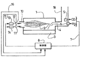
図1は、本発明に係る炉および制御システムの概略図(断面図)である。 FIG. 1 is a schematic view (cross-sectional view) of a furnace and a control system according to the present invention.
バーナ10は、液状形態で金属3を加熱、溶融する炎を作る。炉から排出し、燃焼、特にバーナによって生成される煙道ガス4は、前記煙道中のCOおよび/またはH2濃度を測定するためにCOおよび/またはH2検出器5,6がそれぞれ置かれるライン18を通して除去される。それぞれの検出器5,6から出た信号は、接続ラインを通して操作が以下に説明される制御ユニット8に送信される。前記バーナ10は、適切な流速の酸化剤および燃料を前記バーナに配送するためのそれぞれの制御バルブ12,11(例えばマスフローメータ)を通してそれぞれ酸化剤および燃料が供給される。この流速は、接続ライン15を通して制御デバイス8によって制御される。接続ライン17,16は、前記バルブ12,11の開度の測定を前記制御システム8に送信し、このシステムはまたセンサを通して溶融金属の温度のデータを受信する。前記制御システム8は、特に値C1から値C2に進めるために時間の関数として変換されることができるCO(および/またはH2)濃度目標値の調節を備える。センサ5で前記制御デバイス8に送信されるCOおよび/またはH2濃度の測定が前記目標より高いか低いかによって、制御信号を接続15を通して酸化剤および燃料の注入を調節する制御バルブ12,11に発生し、前記煙道ガスの一酸化炭素および/または水素濃度減少および増加を得る。
The
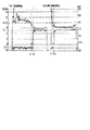
図2は、前述した溶融サイクルの2つの段階処理の状況における比R(酸化剤の流速または好ましくは燃料の流速が一定に保持されている)と煙道ガス中のCOおよび/またはH2濃度の典型的な変形を示す。段階IおよびIIの同じ連続サイクルにおいてC1=C2およびC1<C2(C1=C2であれば、単一段階のみであろう)の全ての場合で、段階Iの間、COおよび/またはH2目標値は0.1vol%と5vol%の間のC1の値に設定され、一方段階IIにおいて、この目標値は実質的に高い、3vol%と15vol%の間の値C2に調節される。溶融が始まるので、COおよび/またはH2を目標値にサーボ制御するために、制御は過剰酸化剤を供給してVOCsを燃焼のために比Rの値を増加する。装填物およびそれらの燃焼によるVOCの生成は、ピークに達し、それから段階Iの最後でゼロに落ちる。比Rは、R MAXで示されるピークに上昇することによるこの傾向をたどり、それから段階Iに減少する。目標値C1のために、前記VOCsが殆ど全て消費される場合、比Rは必然的かつ最終的に既に定義された閾値Sを通過し、それからR MINで示される最小に落ちる。前記比Rが閾値Sに達すると、少量のVOCは装填物に実質的に残り、前記目標値C1より低いCOおよび/またはH2のレベルを生じる。このときから、制御器は比Rを調節し、この目標からのずれを補償するためにさらにそれ(バーナによるCOおよび/またはH2の生産)を減少する。全てのVOCsは、比がR MINに達するときに燃焼される。それから段階IIが始まるので、制御方法を変える時間である。本発明は、t2=t1+Δtによって定義される時間t2で、制御方法で変化を生じさせるために考慮される溶融段階I(時間t1で終結する)の5%と20%の間の検出時間Δtと結合される閾値超過の時間t1を用いることからなる。このとき、目標値はC2に等しくなる。 FIG. 2 shows the ratio R (the oxidant flow rate or preferably the fuel flow rate is kept constant) and the CO and / or H 2 concentration in the flue gas in the two-stage process situation of the aforementioned melting cycle. The typical deformation of is shown. In all cases where C1 = C2 and C1 <C2 (if C1 = C2 it would be only a single stage) in the same continuous cycle of stages I and II, during stage I, CO and / or H 2 targets The value is set to a value of C1 between 0.1 vol% and 5 vol%, while in stage II this target value is adjusted to a substantially high value C2 between 3 vol% and 15 vol%. As melting begins, in order to servo control CO and / or H 2 to a target value, the control supplies excess oxidant to increase the value of ratio R for burning VOCs. The production of VOCs from the charges and their combustion reaches a peak and then falls to zero at the end of stage I. The ratio R follows this trend by rising to the peak indicated by R MAX and then decreases to stage I. For the target value C1, if almost all of the VOCs are consumed, the ratio R inevitably and finally passes the already defined threshold S, and then falls to the minimum indicated by R MIN. When the ratio R reaches the threshold S, a small amount of VOC remains substantially in the charge, resulting in CO and / or H 2 levels below the target value C1. From this point on, the controller adjusts the ratio R and further reduces it (CO and / or H 2 production by the burner) to compensate for deviations from this target. All VOCs are burned when the ratio reaches RMIN. Then Phase II begins, so it's time to change the control method. The present invention has a detection time Δt between 5% and 20% of the melting stage I (which ends at time t1), which is considered to cause a change in the control method at time t2 defined by t2 = t1 + Δt It consists of using a combined threshold excess time t1. At this time, the target value is equal to C2.
本発明の変形によれば、逆の言い方をすれば炉への新鮮な物質の導入を検出すること、および酸化限界段階からVOC燃焼段階への切り替えることができる。事実、段階II間のアルミニウムの装填を考慮すると、装填相対VOCsは放出され、かつ制御器はこの目標値C2からのずれを補償するためにその(バーナによるCOおよび/またはH2の生成を減少すること)を増大することによって比Rを調節する。同様に、比Rは物理処理が段階Iであることを示す、所望の時間t3で閾値Sを越え、それゆえ指示器によって指示される制御方法での変化はt4=t3+Δtで定義される時間t4で生じる。この時間t4で、目標値はそれゆえ上に定義された値C1に復帰される。前記処理制御ユニットにとって、段階IIの終わりはそれゆえ時間t4である。 According to a variant of the invention, in other words it is possible to detect the introduction of fresh material into the furnace and to switch from the oxidation limit stage to the VOC combustion stage. In fact, considering the loading of aluminum during stage II, the loading relative VOCs are released and the controller reduces its (CO and / or H 2 production by the burner to compensate for deviations from this target value C2. The ratio R is adjusted by increasing Similarly, the ratio R exceeds the threshold S at the desired time t3, indicating that the physical process is stage I, and therefore the change in the control method indicated by the indicator is the time t4 defined by t4 = t3 + Δt. It occurs in. At this time t4, the target value is therefore restored to the value C1 defined above. For the process control unit, the end of phase II is therefore time t4.
例
13MWバーナが装着された回転炉において、27トンの塩および27トンのアルミニウムスクラップが装填され、装填物は2550Sm3の天然ガスが消費されるまで加熱され、それから65トンのアルミニウムスクラップ(この例において清涼飲料缶)が再び装填され、前記装填物は追加の850Sm3の天然ガスが消費されるまで加熱される。35トンのアルミニウムスクラップ(アルミニウム切削屑)はそれから再び装填され、その装填物は追加の1350Sm3の天然ガスが消費されるまで加熱され、99トンのアルミニウムはさらに注入され、炉内に存在される塩およびドロスは総量5500Sm3の天然ガスが消費されるまでさらに加熱される。炉内に残存するアルミニウムはそれから流れ出る:9トンのアルミニウム。
EXAMPLE In a rotary furnace fitted with a 13 MW burner, 27 tonnes of salt and 27 tonnes of aluminum scrap are loaded, the charge is heated until 2550 Sm 3 of natural gas is consumed, and then 65 tons of aluminum scrap (in this example The soft drink can) is again loaded and the charge is heated until an additional 850 Sm 3 of natural gas is consumed. 35 tons of aluminum scrap (aluminum swarf) is then reloaded, the charge is heated until an additional 1350 Sm 3 of natural gas is consumed, and 99 tons of aluminum is further injected and present in the furnace The salt and dross are further heated until a total amount of 5500 Sm 3 of natural gas is consumed. The aluminum remaining in the furnace then flows out: 9 tonnes of aluminum.
図3は、前述した2つのアルミニウム装填物の溶融の間に、煙道ガスで測定されたCOの変化および上に定義された比Rの変化を示す。これらの曲線において、方法での自動的変化の効果は明らかに観測できる。事実、本発明に係る指示器は第1装填物が塗装された清涼飲料缶、それゆえ高濃度の有機化合物を持つ、からなるので、時間t2で中間溶融段階変化を始動する。さらに、有機化合物が乏しい第2装填物(アルミニウム切削屑)を溶融する間に、指示器は段階が始まった後の短いt’2で段階変化を制御し、それによって段階IIに適合される制御方法の初期に最適化する。この指示器は、下記表に示すように炉に投入する装填物の種類に係わりなく酸化損失を低減するため貢献する。

Claims (12)
Applications Claiming Priority (2)
| Application Number | Priority Date | Filing Date | Title |
|---|---|---|---|
| FR0450351A FR2866656B1 (en) | 2004-02-25 | 2004-02-25 | PROCESS FOR TREATING ALUMINUM IN A ROTARY OR REVERB FURNACE |
| PCT/FR2005/050074 WO2005085732A1 (en) | 2004-02-25 | 2005-02-07 | Method for processing aluminium in a rotary or reverberating furnace |
Publications (2)
| Publication Number | Publication Date |
|---|---|
| JP2007524003A true JP2007524003A (en) | 2007-08-23 |
| JP2007524003A5 JP2007524003A5 (en) | 2010-08-26 |
Family
ID=34834242
Family Applications (1)
| Application Number | Title | Priority Date | Filing Date |
|---|---|---|---|
| JP2007500266A Pending JP2007524003A (en) | 2004-02-25 | 2005-02-07 | Method for treating aluminum in rotary or reflective furnaces |
Country Status (10)
| Country | Link |
|---|---|
| US (1) | US7655067B2 (en) |
| EP (1) | EP1721111B1 (en) |
| JP (1) | JP2007524003A (en) |
| AT (1) | ATE399296T1 (en) |
| CA (1) | CA2557288A1 (en) |
| DE (1) | DE602005007710D1 (en) |
| ES (1) | ES2308464T3 (en) |
| FR (1) | FR2866656B1 (en) |
| PL (1) | PL1721111T3 (en) |
| WO (1) | WO2005085732A1 (en) |
Cited By (2)
| Publication number | Priority date | Publication date | Assignee | Title |
|---|---|---|---|---|
| JP2009002639A (en) * | 2007-05-02 | 2009-01-08 | Air Products & Chemicals Inc | Method for supplying heat to melting furnace |
| CN102085689A (en) * | 2010-11-26 | 2011-06-08 | 卢文成 | Production method for inorganic foaming board |
Families Citing this family (12)
| Publication number | Priority date | Publication date | Assignee | Title |
|---|---|---|---|---|
| FR2832732B1 (en) * | 2001-11-29 | 2004-02-13 | Air Liquide | USE OF FUME ANALYSIS IN ALUMINUM OVENS |
| FR2854408B1 (en) * | 2003-04-30 | 2006-05-26 | Air Liquide | PROCESS FOR TREATING ALUMINUM IN AN OVEN |
| EP1790738B1 (en) * | 2005-11-29 | 2008-08-13 | Linde Aktiengesellschaft | Control of a melting process |
| US8071062B2 (en) * | 2009-03-06 | 2011-12-06 | Siemens Energy, Inc. | High temperature catalytic process to reduce emissions of carbon monoxide |
| GB2477753B (en) * | 2010-02-11 | 2012-04-18 | Rifat Al Chalabi | Metal recovery process |
| FR2959298B1 (en) * | 2010-04-23 | 2012-09-21 | Air Liquide | FLAME OVEN AND METHOD FOR CONTROLLING COMBUSTION IN A FLAME OVEN |
| PL2664884T3 (en) | 2012-05-18 | 2020-02-28 | Air Products And Chemicals, Inc. | Method and apparatus for heating metals |
| CN105890347B (en) * | 2016-04-29 | 2018-04-10 | 青岛智邦炉窑设计研究有限公司 | A kind of rotary kiln type reduction roasting device and technique |
| US10991087B2 (en) | 2017-01-16 | 2021-04-27 | Praxair Technology, Inc. | Flame image analysis for furnace combustion control |
| KR20200118493A (en) * | 2018-03-02 | 2020-10-15 | 프랙스에어 테크놀로지, 인코포레이티드 | Flame image analysis for furnace combustion control |
| JP2021025882A (en) * | 2019-08-06 | 2021-02-22 | 日本エア・リキード合同会社 | Method for controlling furnace, and analyzer for implementing the same |
| EP3974754A1 (en) * | 2020-09-23 | 2022-03-30 | Nippon Gases Euro-Holding, S.L.U. | System for measuring temperature in a furnace and method for controlling combustion inside the same |
Citations (1)
| Publication number | Priority date | Publication date | Assignee | Title |
|---|---|---|---|---|
| JPS60121235A (en) * | 1983-12-01 | 1985-06-28 | Furukawa Electric Co Ltd:The | Method for melting nonferrous metal in gas firing reverberatory furnace |
Family Cites Families (10)
| Publication number | Priority date | Publication date | Assignee | Title |
|---|---|---|---|---|
| US3759702A (en) | 1971-04-07 | 1973-09-18 | Chemetron Corp | Method of melting aluminum |
| US5616167A (en) * | 1993-07-13 | 1997-04-01 | Eckert; C. Edward | Method for fluxing molten metal |
| US5563903A (en) * | 1995-06-13 | 1996-10-08 | Praxair Technology, Inc. | Aluminum melting with reduced dross formation |
| FR2777075B1 (en) * | 1998-04-02 | 2000-05-19 | Air Liquide | METHOD FOR OPERATING AN OVEN AND DEVICE FOR IMPLEMENTING THE METHOD |
| DE19824573A1 (en) * | 1998-06-02 | 1999-12-09 | Linde Ag | Process for melting metals |
| US6245122B1 (en) * | 2000-01-20 | 2001-06-12 | J. W. Aluminum Company | Apparatus and method for reclaiming scrap metal |
| AT409269B (en) * | 2000-09-08 | 2002-07-25 | Heribert Dipl Ing Dr Summer | METHOD FOR SALTLESS AND OXIDATION-FREE REMELING OF ALUMINUM |
| DE10114179A1 (en) * | 2001-03-23 | 2002-09-26 | Linde Ag | Device for melting aluminum scrap |
| FR2832732B1 (en) * | 2001-11-29 | 2004-02-13 | Air Liquide | USE OF FUME ANALYSIS IN ALUMINUM OVENS |
| FR2854408B1 (en) * | 2003-04-30 | 2006-05-26 | Air Liquide | PROCESS FOR TREATING ALUMINUM IN AN OVEN |
-
2004
- 2004-02-25 FR FR0450351A patent/FR2866656B1/en not_active Expired - Fee Related
-
2005
- 2005-02-07 AT AT05717705T patent/ATE399296T1/en not_active IP Right Cessation
- 2005-02-07 DE DE200560007710 patent/DE602005007710D1/en active Active
- 2005-02-07 WO PCT/FR2005/050074 patent/WO2005085732A1/en active IP Right Grant
- 2005-02-07 JP JP2007500266A patent/JP2007524003A/en active Pending
- 2005-02-07 PL PL05717705T patent/PL1721111T3/en unknown
- 2005-02-07 EP EP05717705A patent/EP1721111B1/en not_active Not-in-force
- 2005-02-07 US US10/589,935 patent/US7655067B2/en active Active
- 2005-02-07 ES ES05717705T patent/ES2308464T3/en active Active
- 2005-02-07 CA CA 2557288 patent/CA2557288A1/en not_active Abandoned
Patent Citations (1)
| Publication number | Priority date | Publication date | Assignee | Title |
|---|---|---|---|---|
| JPS60121235A (en) * | 1983-12-01 | 1985-06-28 | Furukawa Electric Co Ltd:The | Method for melting nonferrous metal in gas firing reverberatory furnace |
Cited By (2)
| Publication number | Priority date | Publication date | Assignee | Title |
|---|---|---|---|---|
| JP2009002639A (en) * | 2007-05-02 | 2009-01-08 | Air Products & Chemicals Inc | Method for supplying heat to melting furnace |
| CN102085689A (en) * | 2010-11-26 | 2011-06-08 | 卢文成 | Production method for inorganic foaming board |
Also Published As
| Publication number | Publication date |
|---|---|
| FR2866656A1 (en) | 2005-08-26 |
| US20070171954A1 (en) | 2007-07-26 |
| ATE399296T1 (en) | 2008-07-15 |
| PL1721111T3 (en) | 2008-11-28 |
| ES2308464T3 (en) | 2008-12-01 |
| DE602005007710D1 (en) | 2008-08-07 |
| US7655067B2 (en) | 2010-02-02 |
| FR2866656B1 (en) | 2006-05-26 |
| WO2005085732A1 (en) | 2005-09-15 |
| EP1721111A1 (en) | 2006-11-15 |
| CA2557288A1 (en) | 2005-09-15 |
| EP1721111B1 (en) | 2008-06-25 |
Similar Documents
| Publication | Publication Date | Title |
|---|---|---|
| JP2007524003A (en) | Method for treating aluminum in rotary or reflective furnaces | |
| JP2007524003A5 (en) | ||
| RU2507461C2 (en) | Furnace operation method, as well as device for implementation of this method | |
| RU2242520C2 (en) | Method of starting up of a process of a direct melting | |
| CN103796735B (en) | A process for incinerating nh3 and a nh3 incinerator | |
| BR112012027190B1 (en) | FUEL FEED OVEN AND METHOD TO CONTROL COMBUSTION IN A FUEL FED OVEN | |
| US20210131734A1 (en) | Furnace system and method for operating a furnace | |
| JP4554596B2 (en) | In-furnace aluminum treatment method | |
| CA2198682A1 (en) | Furnace waste gas combustion control | |
| RU2346057C2 (en) | Advanced method of melting for receiving of iron | |
| JP5406482B2 (en) | Operation control method for fluidized bed incinerator and fluidized bed incinerator | |
| RU2182603C2 (en) | Method of control of rhomelt process | |
| ES2207389B1 (en) | IMPROVEMENTS IN THE OBJECT OF THE MAIN PATENT N.200102624, BY "PROCEDURE FOR THE MELTING OF AN ALUMINUM LOAD". | |
| JP2005213591A (en) | Method for blowing solid fuel into blast furnace and blowing lance | |
| JP4295134B2 (en) | Refining furnace operation method | |
| US20230194082A1 (en) | Combustion process | |
| WO2004083469A1 (en) | Process for melting an aluminum charge containing organic material | |
| US20200284513A1 (en) | Method for controlling a combustion and furnace | |
| SU1364639A1 (en) | Method of heating open-hearth furnace | |
| US6245124B1 (en) | Vertical shaft furnaces | |
| JP2002121612A (en) | Method for melting cold iron | |
| Motlagh | Desulphurization of steel during melting | |
| JPH0470364B2 (en) | ||
| JPH0438815B2 (en) | ||
| JP2005213592A (en) | Method for blowing solid fuel into blast furnace |
Legal Events
| Date | Code | Title | Description |
|---|---|---|---|
| A621 | Written request for application examination |
Free format text: JAPANESE INTERMEDIATE CODE: A621 Effective date: 20071214 |
|
| A524 | Written submission of copy of amendment under article 19 pct |
Free format text: JAPANESE INTERMEDIATE CODE: A524 Effective date: 20100707 |
|
| A131 | Notification of reasons for refusal |
Free format text: JAPANESE INTERMEDIATE CODE: A131 Effective date: 20101026 |
|
| A521 | Request for written amendment filed |
Free format text: JAPANESE INTERMEDIATE CODE: A523 Effective date: 20110120 |
|
| A02 | Decision of refusal |
Free format text: JAPANESE INTERMEDIATE CODE: A02 Effective date: 20110726 |