JP2007511368A - Apparatus for generating a rotating laser beam - Google Patents
Apparatus for generating a rotating laser beam Download PDFInfo
- Publication number
- JP2007511368A JP2007511368A JP2006530193A JP2006530193A JP2007511368A JP 2007511368 A JP2007511368 A JP 2007511368A JP 2006530193 A JP2006530193 A JP 2006530193A JP 2006530193 A JP2006530193 A JP 2006530193A JP 2007511368 A JP2007511368 A JP 2007511368A
- Authority
- JP
- Japan
- Prior art keywords
- laser beam
- reflecting surface
- rotating
- optical system
- rotating laser
- Prior art date
- Legal status (The legal status is an assumption and is not a legal conclusion. Google has not performed a legal analysis and makes no representation as to the accuracy of the status listed.)
- Ceased
Links
- 230000003287 optical effect Effects 0.000 claims abstract description 73
- 230000001681 protective effect Effects 0.000 claims description 11
- 238000012545 processing Methods 0.000 claims description 6
- 230000000007 visual effect Effects 0.000 claims 2
- 238000003466 welding Methods 0.000 abstract description 26
- 238000005520 cutting process Methods 0.000 abstract description 3
- 238000005553 drilling Methods 0.000 abstract description 2
- 238000000227 grinding Methods 0.000 abstract 1
- 210000000695 crystalline len Anatomy 0.000 description 27
- 238000003754 machining Methods 0.000 description 6
- 238000012986 modification Methods 0.000 description 4
- 230000004048 modification Effects 0.000 description 4
- 238000000034 method Methods 0.000 description 3
- 230000004075 alteration Effects 0.000 description 2
- 239000006185 dispersion Substances 0.000 description 2
- 238000005452 bending Methods 0.000 description 1
- 230000015572 biosynthetic process Effects 0.000 description 1
- 239000000470 constituent Substances 0.000 description 1
- 238000001816 cooling Methods 0.000 description 1
- 239000000498 cooling water Substances 0.000 description 1
- 239000000428 dust Substances 0.000 description 1
- 210000000887 face Anatomy 0.000 description 1
- 238000003780 insertion Methods 0.000 description 1
- 230000037431 insertion Effects 0.000 description 1
- 238000007689 inspection Methods 0.000 description 1
- 239000000463 material Substances 0.000 description 1
- 239000002184 metal Substances 0.000 description 1
- 238000013021 overheating Methods 0.000 description 1
- 238000002360 preparation method Methods 0.000 description 1
Images
Classifications
-
- B—PERFORMING OPERATIONS; TRANSPORTING
- B23—MACHINE TOOLS; METAL-WORKING NOT OTHERWISE PROVIDED FOR
- B23K—SOLDERING OR UNSOLDERING; WELDING; CLADDING OR PLATING BY SOLDERING OR WELDING; CUTTING BY APPLYING HEAT LOCALLY, e.g. FLAME CUTTING; WORKING BY LASER BEAM
- B23K26/00—Working by laser beam, e.g. welding, cutting or boring
- B23K26/02—Positioning or observing the workpiece, e.g. with respect to the point of impact; Aligning, aiming or focusing the laser beam
- B23K26/06—Shaping the laser beam, e.g. by masks or multi-focusing
- B23K26/064—Shaping the laser beam, e.g. by masks or multi-focusing by means of optical elements, e.g. lenses, mirrors or prisms
- B23K26/0648—Shaping the laser beam, e.g. by masks or multi-focusing by means of optical elements, e.g. lenses, mirrors or prisms comprising lenses
-
- B—PERFORMING OPERATIONS; TRANSPORTING
- B23—MACHINE TOOLS; METAL-WORKING NOT OTHERWISE PROVIDED FOR
- B23K—SOLDERING OR UNSOLDERING; WELDING; CLADDING OR PLATING BY SOLDERING OR WELDING; CUTTING BY APPLYING HEAT LOCALLY, e.g. FLAME CUTTING; WORKING BY LASER BEAM
- B23K26/00—Working by laser beam, e.g. welding, cutting or boring
- B23K26/02—Positioning or observing the workpiece, e.g. with respect to the point of impact; Aligning, aiming or focusing the laser beam
- B23K26/03—Observing, e.g. monitoring, the workpiece
- B23K26/032—Observing, e.g. monitoring, the workpiece using optical means
-
- B—PERFORMING OPERATIONS; TRANSPORTING
- B23—MACHINE TOOLS; METAL-WORKING NOT OTHERWISE PROVIDED FOR
- B23K—SOLDERING OR UNSOLDERING; WELDING; CLADDING OR PLATING BY SOLDERING OR WELDING; CUTTING BY APPLYING HEAT LOCALLY, e.g. FLAME CUTTING; WORKING BY LASER BEAM
- B23K26/00—Working by laser beam, e.g. welding, cutting or boring
- B23K26/02—Positioning or observing the workpiece, e.g. with respect to the point of impact; Aligning, aiming or focusing the laser beam
- B23K26/06—Shaping the laser beam, e.g. by masks or multi-focusing
- B23K26/064—Shaping the laser beam, e.g. by masks or multi-focusing by means of optical elements, e.g. lenses, mirrors or prisms
- B23K26/0643—Shaping the laser beam, e.g. by masks or multi-focusing by means of optical elements, e.g. lenses, mirrors or prisms comprising mirrors
-
- B—PERFORMING OPERATIONS; TRANSPORTING
- B23—MACHINE TOOLS; METAL-WORKING NOT OTHERWISE PROVIDED FOR
- B23K—SOLDERING OR UNSOLDERING; WELDING; CLADDING OR PLATING BY SOLDERING OR WELDING; CUTTING BY APPLYING HEAT LOCALLY, e.g. FLAME CUTTING; WORKING BY LASER BEAM
- B23K26/00—Working by laser beam, e.g. welding, cutting or boring
- B23K26/08—Devices involving relative movement between laser beam and workpiece
- B23K26/10—Devices involving relative movement between laser beam and workpiece using a fixed support, i.e. involving moving the laser beam
- B23K26/103—Devices involving relative movement between laser beam and workpiece using a fixed support, i.e. involving moving the laser beam the laser beam rotating around the fixed workpiece
-
- B—PERFORMING OPERATIONS; TRANSPORTING
- B23—MACHINE TOOLS; METAL-WORKING NOT OTHERWISE PROVIDED FOR
- B23K—SOLDERING OR UNSOLDERING; WELDING; CLADDING OR PLATING BY SOLDERING OR WELDING; CUTTING BY APPLYING HEAT LOCALLY, e.g. FLAME CUTTING; WORKING BY LASER BEAM
- B23K26/00—Working by laser beam, e.g. welding, cutting or boring
- B23K26/20—Bonding
- B23K26/21—Bonding by welding
- B23K26/24—Seam welding
- B23K26/28—Seam welding of curved planar seams
Landscapes
- Physics & Mathematics (AREA)
- Optics & Photonics (AREA)
- Engineering & Computer Science (AREA)
- Plasma & Fusion (AREA)
- Mechanical Engineering (AREA)
- Laser Beam Processing (AREA)
- Mechanical Optical Scanning Systems (AREA)
- Laser Surgery Devices (AREA)
- Lasers (AREA)
Abstract
溶接、切断、孔開け、研削等のさまざまなアプリケーションに用いることのできる回転レーザービーム(5)を生成する装置(1)を提供すること。
【課題】本発明の装置は、高速で回転し、正確なレーザービームを生成することができる。本発明の装置は、メインの回転可能な光学装置(100)を有し、これは、光学装置が交差する軸(X1)を中心に回転する反射面(102)を有する。
【選択図】図1To provide an apparatus (1) for generating a rotating laser beam (5) that can be used for various applications such as welding, cutting, drilling, grinding and the like.
An apparatus of the present invention can rotate at high speed and generate an accurate laser beam. The device of the present invention has a main rotatable optical device (100), which has a reflective surface (102) that rotates about an axis (X1) that the optical device intersects.
[Selection] Figure 1
Description
本発明は、回転レーザビームを生成する装置に関し、特に正確且つ高速に環状に機械加工および/または溶接を行う装置に関する。このような装置は、環状に機械加工したり溶接する加工分野に適用可能である。 The present invention relates to an apparatus for generating a rotating laser beam, and more particularly, to an apparatus for machining and / or welding in an annular shape accurately and at high speed. Such an apparatus can be applied to a machining field in which machining or welding is performed in an annular shape.
以下の説明は、特に、溶接装置に関するものであるが、レーザビームのパラメータによっては、本発明の装置は、切断、孔開け、材料の切り落とし等の機械加工にも用いられる。 The following description relates in particular to a welding device, but depending on the parameters of the laser beam, the device according to the invention can also be used for machining such as cutting, drilling and material cutting.
レーザビームで環状に溶接するシステムは従来から公知である。 Systems for welding in a ring with a laser beam are known in the art.
このようなシステムのあるものは、溶接装置は、溶接すべき被加工物に対し、固定する方式に基づいている。レーザビームは、被加工物の溶接領域に一定の方向で向けられ、そしてこの被加工物を、レーザ手段を有する支持部材で回転させている。 Some such systems are based on a method in which the welding apparatus is fixed to the workpieces to be welded. The laser beam is directed in a certain direction to the welding area of the workpiece, and this workpiece is rotated by a support member having laser means.
しかし、このようなシステムは欠点がある。例えば、レーザビームに対し、被加工物の位置を正確に調整/配置することが困難であり、特に、被加工物が高速回転している時には致命的である。 However, such a system has drawbacks. For example, it is difficult to accurately adjust / place the position of the workpiece with respect to the laser beam, which is particularly fatal when the workpiece is rotating at high speed.
さらに、大量の被加工物を連続的に溶接する場合には、溶接作業は長時間に及ぶ。実際に、この溶接作業においては、被加工物は、被非加工物を支持する台を高速で回転させる前に、その支持台上に配置しなければならない。その後、溶接作業は、被加工物が所定の回転速度以上になった時点で行われる。溶接作業後、支持台は回転を停止し、被加工物が支持台から取り外され、次の被加工物がその台上に配置される。 Furthermore, when a large amount of workpieces are continuously welded, the welding operation takes a long time. In fact, in this welding operation, the workpieces must be placed on the support table before the table supporting the workpiece is rotated at high speed. Thereafter, the welding operation is performed when the workpiece becomes a predetermined rotational speed or more. After the welding operation, the support table stops rotating, the workpiece is removed from the support table, and the next workpiece is placed on the table.
他のシステムも公知である。例えば、被加工物は溶接作業の間静止状態にあり、レーザビームの方向が溶接領域全体を掃引するように変化するシステムである。レーザビームで溶接領域全体をカバーするために、2枚のミラーを、互いに独立に且つ2つの位置の間で傾斜させて、レーザビームの光学パスに配置する。かくして、第1ミラーは、第1方向X−X’に沿ってレーザビームの動きを制御し、第2ミラーは、第1方向X−X’に直交する第2方向Y−Y’に沿ってレーザビームの動きを制御する。かくして2枚のミラーのそれぞれの傾斜角を組み合わせることにより、被加工物の溶接領域全体をカバーしている。 Other systems are also known. For example, a system in which the workpiece is stationary during the welding operation and the direction of the laser beam changes to sweep the entire welding area. In order to cover the entire weld area with the laser beam, the two mirrors are placed in the optical path of the laser beam, tilted independently of each other and between the two positions. Thus, the first mirror controls the movement of the laser beam along the first direction XX ′, and the second mirror is along the second direction YY ′ orthogonal to the first direction XX ′. Control the movement of the laser beam. Thus, the entire welding area of the workpiece is covered by combining the inclination angles of the two mirrors.
しかし、このシステムの欠点は、溶接領域の寸法が大きくなるに連れて、各ミラーに対する端部位置の間が広がる。かくして、一方の端部から別の端部へミラーを傾斜させるのにかかる時間が長くなり、溶接作業の全体速度が低下することになる。 However, the disadvantage of this system is that the space between the end positions for each mirror increases as the size of the weld area increases. Thus, the time taken to tilt the mirror from one end to the other is lengthened and the overall speed of the welding operation is reduced.
特許文献1に開示された回転レーザビームを生成する装置は、この装置に対して静止位置にある長焦点距離のレンズと、回転する支持台上に搭載される第1反射面とを有する。この第1反射面により反射された光は、第2反射面に向けられ、その後、第3反射面に向けられる。 An apparatus for generating a rotating laser beam disclosed in Patent Document 1 includes a lens having a long focal length at a stationary position with respect to the apparatus, and a first reflecting surface mounted on a rotating support base. The light reflected by the first reflecting surface is directed to the second reflecting surface and then directed to the third reflecting surface.
しかし、この特許文献1に記載された3枚の全ての反射面は、断面が平面上であり、これらの反射面が長焦点レンズと組合わさった時には、溶接すべき被加工物上に形成される像焦点の形状に誤差を導入することになる。 However, all of the three reflecting surfaces described in Patent Document 1 have a flat cross section, and when these reflecting surfaces are combined with a long focal length lens, they are formed on the workpiece to be welded. An error is introduced into the shape of the image focus.
本発明の第1目的は、従来技術のシステムを改善することであり、被加工物を環状に機械加工を高速且つ信頼性高く実行する装置を提供することである A first object of the present invention is to improve the system of the prior art and to provide an apparatus for performing machining of a workpiece in an annular shape at high speed and with high reliability.
本発明は、レーザビームを供給する手段を有する装置に関する。レーザビームは、レーザ装置の光学システムを通る光学パスに沿い、この装置の出力点から出射され、被加工物の衝突(例:溶接)領域即ち入射領域に入る。本発明の光学システムは、中心軸X1を有し、入射領域におけるレーザビームの像焦点(image focal point)の位置を調整する。 The present invention relates to an apparatus having means for supplying a laser beam. The laser beam is emitted from the output point of the apparatus along an optical path through the optical system of the laser apparatus and enters the work piece impact (eg, welding) or incident area. The optical system of the present invention has a central axis X1 and adjusts the position of the image focal point of the laser beam in the incident area.
本発明の光学システムは、第1反射面と第2反射面とを有する。第1反射面は、中心軸X1に対して回転可能であり、且つレーザビームを第2反射面の方向に向け、第2反射面は、レーザビームを被加工物の方向に反射させる。本発明の装置は、第1反射面と回転中の光学システムとを駆動する手段を含む。本発明の装置は、光学システムは傾斜可能に配置された光学軸X2を有する回転レンズを含む。その結果、光学軸X2は、中心軸X1に対して傾斜可能である。これにより、被加工物上の像焦点の品質を向上させる。 The optical system of the present invention has a first reflecting surface and a second reflecting surface. The first reflecting surface is rotatable with respect to the central axis X1, and directs the laser beam toward the second reflecting surface, and the second reflecting surface reflects the laser beam toward the workpiece. The apparatus of the present invention includes means for driving the first reflecting surface and the rotating optical system. The apparatus of the present invention includes a rotating lens having an optical axis X2 in which the optical system is tiltably arranged. As a result, the optical axis X2 can be tilted with respect to the central axis X1. This improves the quality of the image focus on the workpiece.
かくして、例えば環状の機械加工/溶接が、反射面を単に回転動作させるだけで行うことができ、これにより、高速回転が可能となり、この回転速度は溶接の寸法とは無関係に設定できる。 Thus, for example, annular machining / welding can be performed by simply rotating the reflective surface, thereby enabling high speed rotation, which can be set independently of the size of the weld.
傾斜可能レンズが第1反射面と共に回転するために、被加工物上の像焦点の品質を微細に調整できる。この最後の特徴は、上記の公知のシステムに対して重要な改善点である。従来システムは、レーザビームの品質の調整ができないのに対し、本発明の調整は、反射面の動きを考慮に入れている。 Since the tiltable lens rotates with the first reflecting surface, the quality of the image focus on the workpiece can be finely adjusted. This last feature is an important improvement over the known system described above. Conventional systems cannot adjust the quality of the laser beam, whereas the adjustment of the present invention takes into account the movement of the reflecting surface.
本発明の一実施例によれば、第1反射面は光学システム内で固定配置される。この光学システムは、中心軸X1に対してモータ手段で回転可能である。 According to an embodiment of the invention, the first reflecting surface is fixedly arranged in the optical system. This optical system can be rotated by motor means with respect to the central axis X1.
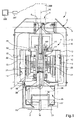
図1に本発明のレーザビーム溶接装置1が示されている。レーザビーム溶接装置1はメインハウジング2を有し、その中にレーザビーム溶接装置1の構成要素の大部分が収納される。ハウジング2は、被加工物の上方に、作業台3上に配置されるツール(図示せず)を保持する手段、例えば脚を有する。
FIG. 1 shows a laser beam welding apparatus 1 of the present invention. The laser beam welding apparatus 1 has a
ハウジング2は側面開口4を有し、この側面開口4をレーザビーム5が水平方向に貫通する。前記レーザビームは、遠隔操作されるレーザソース(図示せず)から生成される。レーザビーム5は、入射レーザビームに対し45度の角度を向いた半透明ミラー6に向けられ、この半透明ミラー6がレーザビームをほぼ垂直方向に向ける。
The
上部開口7が、半透明ミラー6の後方に、従来と同様に、配置される。この開口は、光学センサー200(例えばCCDカメラ)を配置するための観測窓である。光学センサー200は、プロセッサを有する信号処理装置201に接続され、この信号処理装置201はディスプレイ202に接続される。
The upper opening 7 is arranged behind the translucent mirror 6 in the same manner as in the prior art. This opening is an observation window for placing the optical sensor 200 (for example, a CCD camera). The
半透明ミラー6から下方向に向かうレーザビーム5の光学パスに沿って、チェンバ8が具備される。その中に可動ユニット9が中心軸X1の方向に直進できるよう、一部収納されている。可動ユニット9は、中心軸X1に平行な方向に延びる側面アーム10を介して、ハウジング2に接続され、ハウジング2の内側表面に配置された支持用延長部12の穴11と共働する。好ましくは、ボールベアリング13が、支持用延長部12の端部と穴11の間に挿入され、可動ユニット9が移動した時に、これら2つの要素の間のスライド動作を改善している。可動ユニット9の垂直方向の動きは、ハウジング2を介して調整される。これは、適宜の手段(例えば微細ネジ)で行われる。
A chamber 8 is provided along the optical path of the laser beam 5 directed downward from the semitransparent mirror 6. A part of the movable unit 9 is accommodated therein so that it can go straight in the direction of the central axis X1. The movable unit 9 is connected to the
可動ユニットは、中心に配置された光学システム100を有する。光学システム100は、スリーブ101により半径方向が規定される。スリーブ101は、離間した2つの環状ステップ部16を有し、その上にボールベアリング17が当接して、スリーブ101の位置を可動ユニット9に対して中心軸X1の方向に、且つ半径方向ではスリーブ101をガイドするように保持する。環状ネジ部材であるナット18が、スリーブ15のフロントエンド19のネジ部分と噛み合って、ボールベアリング17を対応する環状ステップ部16に対し、固定する。
The movable unit has an
ロータ20は、スリーブ101の周囲に直接配置される。このロータ20は2極の永久磁石の形態で形成される。
The
ステータ21は、ロータ20の周囲に同心上に配置される。ステータ21は、複数のコイル22を具備し、その内の2つが図に示されている。かくして、ロータ20とステータ21の組み合わせにより、モータを構成し、そのパワー供給手段が参照番号23として示されている。このモータの動作により、光学システム100が、スリーブ101の回転により回転動作を起こす。
The
可動ユニット9は、その下部部分にブロック24を有し、その中に中央空洞部25を具備する。この中央空洞部25は、第1の上部環状ミラー26と第2の下部環状ミラー27とを有する。図1に示されるように、両環状ミラー26、27は、断面が平面形状である。
The movable unit 9 has a block 24 in a lower part thereof, and a
従来手段が、ミラー26、27のそれぞれの位置を正確に調整するために具備される。例えば、対応するミラーから離間配置されたネジとスプリングの組(図示せず)である。かくして、ミラー26、27の軸の中心軸X1に対する傾斜を調整して、被加工物にレーザビームが入射する前のレーザビームの品質を制御する。
Conventional means are provided to accurately adjust the position of each of the
ブロック24は、装置のハウジング2に対し、複数のネジ部材28により保持される。
さらに、ブロック24は、カップ形状の保護窓30により閉じられた中央開口29を有する。この保護窓30は、レーザ装置の光学要素が溶接作業中にゴミあるいはプラズマにより汚染されるのを阻止する。中心軸X1とミラー26、27に対し、保護窓30の位置を正確に調整する手段が具備される。例えば、ネジ部材31である。
The block 24 is held by a plurality of
Further, the block 24 has a
保護窓30は、レーザビーム5の光束に直交するという要件を満たす限り、さまざまな形態を採ることができる。保護窓30は、レーザビームの伝搬に対し、光学的機能をを負わない。言い換えると、保護窓30の形状は、本発明の範囲内において、保護窓30の領域におけるレーザビーム5の伝搬方向に依存して、すなわち反射表面構造に依存して、様々変形例が可能である。
The
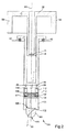
図2を参照して光学システム100を詳述する。同図において、スリーブ101は、光学部分のみを記載するために、省いている。
The
図2を参照すると、第1管状要素32は、可動ユニット9に対し静止しており、サポートフレームを規定する複数の半径方向延長部33を有する。第1管状要素32の端部34の領域には、レンズ35が配置され、このレンズ35の主な機能は、レーザビーム5の分散を抑えることである。
Referring to FIG. 2, the first
第1管状要素32は、第2管状要素38により部分的に包囲されている。その機能は、後述する。
The first
光学システム100は、スリーブ103を有する。このスリーブ103は、特に、光学装置104を有する。この光学装置104は、入力平面105と出力半球面106とを有する。
The
本発明の一実施例においては、光学装置104は、水晶体であり、その中に反射面102を形成する平面状のギャップが具備される。このギャップは、空気で満たされ、中心軸X1に対し、ある角度で方向付けられており、これにより、図1に示す入射レーザビームの方向を変える。光学装置104は、スリーブ103内で摩擦力により保持されている。
In one embodiment of the invention, the
反射面102は、本発明の範囲内で当業者は適宜の形状にできる。しかし、ミラーを使用することは、レーザビームの高出力故に、過熱のリスクがあるために、ギャップを使用するほど効率的ではない。かくして、従来のミラーの使用も可能であり、特に、ハイパワーのレーザビームが必要でないようなアプリケーションではそうである。
The
別の観点からすると、光学装置104の開示された形状は、光学システムの回転中に発生する慣性の点で有利である。
From another point of view, the disclosed shape of the
さらに、スリーブ103は、支持部材108により支持されている収束レンズ107を収納する。支持部材108は、スリーブ103に、図2の面に直交する方向に互いに整合している2個のピボットピン(図示せず)により機械的に接続される。支持部材は、第1ピン109、第2ピン110を有し、これらは互いに且つ中心軸X1の方向に平行で、支持部材108の非貫通孔(blind hole)に入るよう配列される。
Further, the
第1ピン109は、螺旋状のスプリング111により、その孔内に支持され、一方第2ピン110は、その孔に対し一定の位置に、挿入、ネジ込み(図示せず)により保持される。
The
管状要素112は、スリーブ103に通され、第1ピン109と第2ピン110にその下側表面で当接する。それ故に、図2から明らかなように、管状要素112が、支持部材108の方向の下側方向に挿入されると、力が第1ピン109と第2ピン110に掛かる。第2ピン110は支持部材108に固定されているために、第1ピン109にかかる力が増加しながら、支持部材108がピンを軸に回転運動(支軸動作)を引き起こす。従って、第1ピン109に掛かる力は、スプリング111に伝達され、さらに圧縮されて、力を吸収する。
The
その結果、収束レンズ107は傾斜する。言い換えると、光学軸X2は、中心軸X1に対して回転する。上記の例では、光学軸X2は時計方向に回転する(図2)。
As a result, the
第2管状要素38は、光学システム100の外部から管状要素112を操作するツールの役目をする。図2から分かるように、第2管状要素38は、複数の短いロッド39を有する。ロッド39は、第2管状要素38の下部表面から突出し、管状要素112の上部表面に具備された対応する非貫通孔113にはまる。第2管状要素38は、作業者が支持スプリング40を圧縮することにより、下方向に移動する。その結果、ロッド39が孔113に入る。その後、支持スプリング40が圧縮されながら、第2管状要素38が回転して管状要素112の回転運動を引き起こし、その結果、収束レンズ107を傾斜させる。第2管状要素38にかかる圧が解かれると、ロッド39は、孔113から解放され、管状要素112は一定の角度位置を保持する。
The second
収束レンズ107の機能は、レーザビーム5に作用して、溶接領域の像焦点の形状の収差の発生を回避すること、すなわち像焦点の品質を改善することである。
The function of the converging
同じ理由で、ミラー26、27のそれぞれの表面は、その伝搬プロセスの間、非常に注意深く取り扱わなければならない。ミラー表面の準備の高品質故に、像焦点の品質が向上する。
For the same reason, each surface of the
図1から明らかなように、本発明の装置を通過するレーザビーム5の光学パスは、光学システム100がモータにより回転駆動した時に、環状の溶接が可能となるようなものである。
As is apparent from FIG. 1, the optical path of the laser beam 5 passing through the apparatus of the present invention is such that annular welding is possible when the
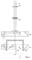
図3を参照して、本発明による装置で行われる光学原理を説明する。 With reference to FIG. 3, the optical principle performed in the apparatus according to the invention will be described.
可動ユニット9が中間位置にある時には、被加工物の入射(衝突)領域の像焦点は、F0にある。 When the movable unit 9 is in the intermediate position, the image focal point of the workpiece incident (collision) region is F0.
この状態からスタートして、ユーザは、可動ユニット9を上下に動かして、操作中にレーザビームにより走査される円の半径の値を、被加工物の寸法に応じて調整する。像焦点が、レーザビームの光学パスに沿って、可動ユニット9の移動と共に移動する。可動ユニット9がハウジング2に対し最高位置に配置された時には、像焦点はF1’にあり、可動ユニット9が最低位置に配置された時には、像焦点はF1にある。
Starting from this state, the user moves the movable unit 9 up and down and adjusts the value of the radius of the circle scanned by the laser beam during operation according to the size of the workpiece. The image focus moves along with the movement of the movable unit 9 along the optical path of the laser beam. When the movable unit 9 is disposed at the highest position with respect to the
焦点の位置の調整に関して説明した方法は、単なる例示で、限定的に解釈すべきものではない。異なる数のレンズあるいは異なる特性のレンズを選択することによりさまざまな変形例が可能である。 The method described with respect to the focus position adjustment is merely illustrative and should not be construed as limiting. Various modifications are possible by selecting different numbers of lenses or lenses with different characteristics.
光学システム100の入力点から出射すると、レーザビーム5は、レンズ35に入射するときには若干分散している。このレンズ35の機能は、ビームの分散を減少させることである。光学パスは、その後、傾斜可能な収束レンズ107を通り収束し、その焦点距離は、適宜選択できる。より具体的には、収束レンズ107の焦点距離は、本発明の装置の寸法に合わせて、被加工物の表面上に像焦点が形成されるように合わせることができる。
When exiting from the input point of the
前述したように、収束レンズ107は、第1反射面102に平行な軸の周囲で軸支可能である。その結果、光学軸X2は中心軸X1に対し傾斜する。かくして、被加工物の表面に形成された像焦点の品質は、例えば楕円状の焦点の形成を回避するために、収束レンズ107をピボット動作(軸支運動)させることにより微調整可能である。この最後の特徴は、傾斜可能な収束レンズ107と第1反射面102が一緒に回転し、その相互の方向が装置の動作中一定であるが故に、特に重要である。
As described above, the converging
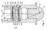
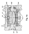
図4、4aを参照すると、本発明のスリーブ103の別の実施例が示されており、これは、図2の実施例を用いて以下説明する。
Referring to FIGS. 4 and 4a, another embodiment of the
特に、本発明は、収束レンズ107を支持する構造体の変形例に関し、光学軸X2と中心軸X1の間の方向角の調整手段を具備する。
In particular, the present invention relates to a modification of the structure that supports the converging
支持部材408は、スリーブ103に2個のピボットピン401、402の手段により機械的に固定される。このピボットピン401、402は、互いに図4の面に直交する方向、すなわち図4aの面に沿って整合している。
The
第1軟質リング403、404が、それぞれ、支持部材408の両側に具備される。これらの各リングは、平坦なリングを複数重ね合わせたものから形成される(図4,4a)。好ましくは、平坦なリングは、金属製で、それらの周囲で少なくとも部分的に溶接あるいは接着される。
First
各軟質リング403、404は、2個の孔405、406を有する。この孔405,406は、その厚み方向に貫通し、直径方向に対向して配置される。第1ネジ部材409、410が、各孔405,406内に配置される。
Each
各軟質リングの第1ネジ部材409は、軟質リングを接続領域で支持部材408に締め付ける。それぞれの接続領域は、直径方向に向かい合っている。
The
各軟質リングの第2ネジ部材410は、平坦なリングが互いに結合した状態に保持するものであり、対応する第1ネジ部材409よりも短い。全てのネジの頭は、軟質リングから支持部材408に対向する側に突出する。
The
従って、第1軟質リング403からのネジ頭は、管状要素112に当接する(図2)。一方、第2軟質リング404からのネジ頭は、スリーブ103の内側に形成されたステップ411に当接する。
Accordingly, the screw head from the first
支持部材408により形成された組立体の機能は、2個の軟質リング403、404と共に以下説明する。
The function of the assembly formed by the
図2で説明したのと同様に、管状要素112は支持部材408の方向にねじ込まれ、あるいは挿入され、力が第1軟質リング403のネジ頭に掛かる。
As described in FIG. 2, the
力が掛かった状態で、第1軟質リング403は曲げられ、第2軟質リング404も曲げられる。支持部材408は、剛性があり曲げに強い。軟質リング403、404の両方が、それぞれ曲げられた結果、支持部材408と収束レンズ107の光学軸X2は、中心軸X1の方向に対して傾斜する。特に、管状要素112が、図4に示されるようにネジ込まれるあるは挿入されると、収束レンズ107は時計方向に回転する。
In a state where a force is applied, the first
収束レンズ107の機能は、レーザビーム5に作用して、溶接領域の像焦点の形状の収差の発生を回避すること、すなわち像焦点の品質を改善することである。
The function of the converging
より一般的には、本発明の装置の重要な態様は、収束レンズ107と第1反射面102が同時に回転することである。
More generally, an important aspect of the apparatus of the present invention is that the converging
本発明の装置は、さまざまなアプリケーションで用いることができる。例えば、上記したように、光学センサー200と組み合わせて観測窓を用いることにより検査装置としても用いることができる。この場合、ハウジング2の側面開口4は、装置に入力されるレーザビームがないために必要ない。しかし、この側面開口4をそのまま保持して光源の入力点として用いて、検査すべき被加工物の領域を照らして観測画像のコントラストを向上させてもよい。
The apparatus of the present invention can be used in various applications. For example, as described above, the observation window can be used in combination with the
本発明の他の態様は、一連の被加工物を処理する際に、光学システムが処理すべき2個の連続する間で回転を維持することである。レーザビーム供給手段は、処理された被加工物を取り除いたり、新たな被加工物を配置するのに必要な時間だけ停止するだけでよく、これによりユーザの加工時間を節約できる。 Another aspect of the present invention is to maintain rotation between two consecutive to-be-processed optical systems when processing a series of workpieces. The laser beam supply means need only be stopped for the time required to remove the processed workpiece or place a new workpiece, thereby saving the user's processing time.
さらなる便利な特徴が上記の装置に本発明の範囲を離れることなく追加できる。例えば、冷却水供給回路をボールベアリング17を冷却するために具備することもできる。光学システムの回転速度を測定する装置も具備することができる。
Additional convenient features can be added to the above apparatus without departing from the scope of the present invention. For example, a cooling water supply circuit can be provided for cooling the
以上の説明は、本発明の一実施例に関するもので、この技術分野の当業者であれば、本発明の種々の変形例を考え得るが、それらはいずれも本発明の技術的範囲に包含される。特許請求の範囲の構成要素の後に記載した括弧内の番号は、図面の部品番号に対応し、発明の容易なる理解の為に付したものであり、発明を限定的に解釈するために用いてはならない。また、同一番号でも明細書と特許請求の範囲の部品名は必ずしも同一ではない。これは上記した理由による。 The above description relates to one embodiment of the present invention, and those skilled in the art can consider various modifications of the present invention, all of which are included in the technical scope of the present invention. The The numbers in parentheses described after the constituent elements of the claims correspond to the part numbers in the drawings, are attached for easy understanding of the invention, and are used for limiting the invention. Must not. In addition, the part numbers in the description and the claims are not necessarily the same even with the same number. This is for the reason described above.
1 レーザビーム溶接装置
2 メインハウジング
3 作業台
4 側面開口
5 レーザビーム
6 半透明ミラー
7 上部開口
8 メインチェンバ
9 可動ユニット
10 側面アーム
11 穴
12 支持用延長部
13 ボールベアリング
15 スリーブ
16 環状ステップ部
17 ボールベアリング
18 ナット
19 フロントエンド
20 ロータ
21 ステータ
22 コイル
23 レーザ
24 ブロック
25 中央空洞部
26 第1上部環状ミラー
27 第2下部環状ミラー
28 ネジ部材
29 中央開口
30 保護窓
31 ネジ部材
32 第1管状要素
33 半径方向延長部
34 端部
35 レンズ
38 第2管状要素
39 ロッド(棒)
X1 中心軸
X2 光学軸
被加工物
100 光学システム
101 スリーブ
102 反射面
103 スリーブ
104 光学装置
105 入力平面
106 出力半球面
107 収束レンズ
108 支持部材
109 第1ピン
110 第2ピン
111 スプリング
112 管状要素(環状?)
113 ブラインドホール
200 光学センサー
201 信号処理装置
202 ディスプレイ
401,402 ピボットピン
403 第1軟質リング
404 第2軟質リング
405,406 孔
408 支持部材
409 第1ネジ部材
410 第2ネジ部材
411 ステップ
DESCRIPTION OF SYMBOLS 1 Laser
X1 Central axis X2
113
Claims (19)
(A) レーザビームの入力手段(4)と、
前記レーザビームは、前記回転レーザビーム生成装置の光学システム(100)を通る光学パスに従い、前記装置から出力点(29)を介して出力され、被加工物の入射領域に入り、
前記光学システムは、中心軸(X1)を有し、前記入射領域の前記レーザビームの像焦点(F0、F1、F1’)の位置を調整し、
前記光学システムは、前記中心軸(X1)を中心に回転可能な第1反射面(102)を有し、
前記第1反射面(102)は、前記レーザビームを前記被加工物の方向に反射させるよう、第2反射面(26)の方向にレーザビームを方向付け、
(B) 前記第1反射面(102)を前記光学システムと共に、相互方向は一定にしながら、回転させる手段(20、21、22)と
を有し、
前記光学システム(100)は、傾斜可能な光学軸(X2)を有する回転レンズ(107)を有し、
前記光学軸(X2)は、前記中心軸(X1)に対し傾斜し、前記被加工物上の焦点の品質を向上させ、
前記レーザビームの光学パスは、第1反射面(102)に入る前に、前記回転レンズ(107)を通る
ことを特徴とする回転レーザビーム生成装置。 In a rotating laser beam generator for generating a rotating laser beam (5) in order to weld and / or machine a workpiece (W) annularly,
(A) Laser beam input means (4);
The laser beam follows an optical path through the optical system (100) of the rotating laser beam generating device, is output from the device via an output point (29), and enters the incident area of the workpiece.
The optical system has a central axis (X1) and adjusts the position of the image focus (F0, F1, F1 ′) of the laser beam in the incident area;
The optical system has a first reflecting surface (102) rotatable about the central axis (X1),
The first reflecting surface (102) directs the laser beam in the direction of the second reflecting surface (26) so as to reflect the laser beam in the direction of the workpiece,
(B) means (20, 21, 22) for rotating the first reflecting surface (102) together with the optical system while keeping the mutual direction constant;
The optical system (100) comprises a rotating lens (107) having a tiltable optical axis (X2);
The optical axis (X2) is inclined with respect to the central axis (X1) to improve the quality of the focus on the workpiece;
The optical path of the laser beam passes through the rotating lens (107) before entering the first reflecting surface (102).
ことを特徴とする請求項1記載の回転レーザビーム生成装置。 The rotating laser beam generating apparatus according to claim 1, wherein the first reflecting surface (102) is fixedly disposed on the optical system (100).
ことを特徴とする請求項2記載の回転レーザビーム生成装置。 The rotating laser beam generating apparatus according to claim 2, wherein the second reflecting surface reflects the laser beam in the direction of the central axis (X1).
前記第2反射面と第3反射面とは、断面が平面形状である
ことを特徴とする請求項2記載の回転レーザビーム生成装置。 The optical system (100) further comprises a third reflecting surface (26),
The rotating laser beam generating apparatus according to claim 2, wherein the second reflecting surface and the third reflecting surface have a planar shape in cross section.
ことを特徴とする請求項4記載の回転レーザビーム生成装置。 The rotating laser beam generator according to claim 4, wherein the third reflecting surface reflects the laser beam in the direction of the central axis (X1).
(X) 前記第1反射面(102)と前記回転レンズ(107)が配置されるスリーブ(103)と、
前記回転レンズ(107)は、支持部材(108、408)により支持され、
前記支持部材(108、408)は、前記スリーブに直径方向に対向した2本のピン(401、402)により傾斜可能に機械的に取り付けられ、
(Y) 前記スリーブ(103)の内側で前記支持部材に当接して配置される環状要素(112)と
これにより、前記光学軸(X2)と中心軸(X1)との間の角度を調整する
を有し、
ことを特徴とする請求項5記載の回転レーザビーム生成装置。 The optical system (100) comprises:
(X) a sleeve (103) on which the first reflecting surface (102) and the rotating lens (107) are disposed;
The rotating lens (107) is supported by support members (108, 408),
The support member (108, 408) is mechanically attached to the sleeve by two pins (401, 402) diametrically opposed to each other so as to be tiltable.
(Y) an annular element (112) disposed in contact with the support member inside the sleeve (103);
Thereby, adjusting the angle between the optical axis (X2) and the central axis (X1),
The rotating laser beam generator according to claim 5.
前記ロッドは、前記支持部材の上部表面から突出し、前記ピンの方向と直交する方向に沿って半径方向に対向して配置され、
前記ロッドの内の第1ロッド(110)は、前記支持部材(108)に固定され、
前記ロッドの内の第2ロッド(109)は、孔内に配置され、スプリング(111)により支持される
ことを特徴とする請求項6記載の回転レーザビーム生成装置。 The optical system (100) has two rods (109, 110);
The rod protrudes from the upper surface of the support member, and is disposed in a radial direction along a direction orthogonal to the direction of the pin,
A first rod (110) of the rods is fixed to the support member (108),
The rotating laser beam generator according to claim 6, wherein the second rod (109) of the rods is disposed in the hole and supported by a spring (111).
前記各軟質リングは、ある角度で前記支持部材の領域に結合され、
前記軟質リングと支持部材とのそれぞれの接続領域は、半径方向に対向し、
前記支持部材(408)と前記2個の軟質リング(403、404)とは、一方で環状要素(112)に当接し、他方で、スリーブ(103)に具備されたステップ(411)に当接する組立体を形成する
ことを特徴とする請求項7記載の回転レーザビーム生成装置。 The support member (108) has two soft rings (403, 404) disposed on both sides of the support member (408), respectively.
Each soft ring is coupled to an area of the support member at an angle;
Each connection region of the soft ring and the support member is opposed in the radial direction,
The support member (408) and the two soft rings (403, 404) abut on the annular element (112) on the one hand and abut on the step (411) provided on the sleeve (103) on the other hand. 8. The rotating laser beam generating apparatus according to claim 7, wherein an assembly is formed.
前記管状要素(38)は、前記スリーブ(103)と部分的に係合し、前記環状要素(112)と共働する手段を具備し、
前記環状要素(112)は、前記中心軸(X1)に対し、回転し、
前記中心軸(X1)の方向に対する前記環状要素(112)の位置は、前記スリーブ(103)の外側から調整可能である
ことを特徴とする請求項7記載の回転レーザビーム生成装置。 The optical system (100) further comprises a tubular element (38),
Said tubular element (38) comprises means for partially engaging said sleeve (103) and cooperating with said annular element (112);
The annular element (112) rotates relative to the central axis (X1);
The rotating laser beam generating device according to claim 7, wherein the position of the annular element (112) with respect to the direction of the central axis (X1) is adjustable from the outside of the sleeve (103).
前記光学装置(104)は、レーザビーム(5)の伝搬方向に沿って平面状入力表面(105)と半球状出力表面(106)とを有し、
前記第1反射面(102)は、平面状のギャップで形成される
ことを特徴とする請求項7記載の回転レーザビーム生成装置。 The first reflective surface (102) is disposed in the optical device (104),
The optical device (104) has a planar input surface (105) and a hemispherical output surface (106) along the propagation direction of the laser beam (5),
The rotating laser beam generator according to claim 7, wherein the first reflecting surface (102) is formed by a planar gap.
ことを特徴とする請求項10記載の回転レーザビーム生成装置。 11. The rotating laser beam generator according to claim 10, wherein the first reflecting surface (102) intersects the central axis (X1) at the center of curvature of the hemispherical output surface (106). .
ことを特徴とする請求項11記載の回転レーザビーム生成装置。 12. The rotating laser beam generator according to claim 11, wherein the optical system (100) has a protective window (30) in the region of the output (29) of the device.
ことを特徴とする請求項12記載の回転レーザビーム生成装置。 The rotating laser according to claim 12, wherein the protective window (30) has a shape arranged such that a central beam of the laser beam (5) intersects the protective window (30) at right angles. Beam generator.
ことを特徴とする請求項5記載の回転レーザビーム生成装置。 6. The rotating laser beam generator according to claim 5, wherein the quality of the image focus (F0, F1, F1 ′) is adjusted by an angle between the optical axis (X2) and the central axis (X1).
前記ハウジングは、前記レーザビーム入力手段(4)を有し、
(F) 可動ユニット(9)と
をさらに有し、
前記可動ユニットは、前記ハウジング内に少なくとも部分的に収納され、少なくとも前記光学システム(100)と前記第2反射面(26)とを有し、
前記可動ユニット(9)は、前記中心軸(X1)の方向に沿って、前記ハウジング(2)に対し、移動可能であり、これにより前記中心軸(X1)に沿って、その位置を調整する
ことを特徴とする請求項1記載の回転レーザビーム生成装置。 (C) Housing (2)
The housing has the laser beam input means (4);
(F) further having a movable unit (9),
The movable unit is at least partially housed in the housing and includes at least the optical system (100) and the second reflective surface (26);
The movable unit (9) is movable with respect to the housing (2) along the direction of the central axis (X1), thereby adjusting its position along the central axis (X1). The rotating laser beam generating apparatus according to claim 1.
ことを特徴とする請求項1記載の回転レーザビーム生成装置。 The drive means includes a rotor (20) fixedly arranged around the optical system (100) and a stator (21) arranged in the movable unit around the rotor (20). The rotating laser beam generator according to claim 1.
ことを特徴とする請求項1記載の回転レーザビーム生成装置。 The rotating laser beam generating apparatus according to claim 1, further comprising an observation window (7) capable of observing the incident region.
ことを特徴とする請求項17記載の回転レーザビーム生成装置。 18. The rotating laser beam generator according to claim 17, wherein the observation window (7) is connected to a visual device (200, 201, 202).
ことを特徴とする請求項18記載の回転レーザビーム生成装置。 19. The rotating laser beam generator according to claim 18, wherein the visual device comprises a camera (200), an image processing circuit (201), and a monitor (202).
Applications Claiming Priority (2)
| Application Number | Priority Date | Filing Date | Title |
|---|---|---|---|
| EP03011210A EP1477264A1 (en) | 2003-05-16 | 2003-05-16 | Apparatus for generating a rotating laser beam |
| PCT/EP2004/050799 WO2004101213A1 (en) | 2003-05-16 | 2004-05-13 | Apparatus for generating a rotating laser beam comprising a tiltable lens |
Publications (1)
| Publication Number | Publication Date |
|---|---|
| JP2007511368A true JP2007511368A (en) | 2007-05-10 |
Family
ID=33016915
Family Applications (2)
| Application Number | Title | Priority Date | Filing Date |
|---|---|---|---|
| JP2006530192A Expired - Fee Related JP4748728B2 (en) | 2003-05-16 | 2004-05-13 | Apparatus for generating a rotating laser beam |
| JP2006530193A Ceased JP2007511368A (en) | 2003-05-16 | 2004-05-13 | Apparatus for generating a rotating laser beam |
Family Applications Before (1)
| Application Number | Title | Priority Date | Filing Date |
|---|---|---|---|
| JP2006530192A Expired - Fee Related JP4748728B2 (en) | 2003-05-16 | 2004-05-13 | Apparatus for generating a rotating laser beam |
Country Status (7)
| Country | Link |
|---|---|
| US (2) | US7399946B2 (en) |
| EP (3) | EP1477264A1 (en) |
| JP (2) | JP4748728B2 (en) |
| CN (2) | CN100479973C (en) |
| AT (2) | ATE342146T1 (en) |
| DE (2) | DE602004002775T2 (en) |
| WO (2) | WO2004101213A1 (en) |
Cited By (2)
| Publication number | Priority date | Publication date | Assignee | Title |
|---|---|---|---|---|
| CN102079135A (en) * | 2010-12-24 | 2011-06-01 | 中国科学院长春光学精密机械与物理研究所 | Three-dimensional laser plastic welding processing head |
| US9868179B2 (en) | 2012-03-09 | 2018-01-16 | TOYOKOH, Co., Ltd. | Laser irradiation device, laser irradiation system, and method for removing coating or adhering matter |
Families Citing this family (37)
| Publication number | Priority date | Publication date | Assignee | Title |
|---|---|---|---|---|
| EP1477264A1 (en) * | 2003-05-16 | 2004-11-17 | Lasag Ag | Apparatus for generating a rotating laser beam |
| EP1504829B1 (en) | 2003-08-05 | 2006-06-07 | Lasag Ag | Process of manufacturing a medical needle |
| WO2006133044A1 (en) * | 2005-06-06 | 2006-12-14 | Graham Packaging Company, L.P. | System and method for laser trimming/scoring a plastic container with a rotatable and translatable axial beam guide |
| US8560047B2 (en) | 2006-06-16 | 2013-10-15 | Board Of Regents Of The University Of Nebraska | Method and apparatus for computer aided surgery |
| KR20080077424A (en) * | 2007-02-20 | 2008-08-25 | 삼성에스디아이 주식회사 | Secondary Battery and Manufacturing Method Thereof |
| DE102007038502B4 (en) * | 2007-08-14 | 2013-01-03 | Fraunhofer-Gesellschaft zur Förderung der angewandten Forschung e.V. | Method for joining at least two workpieces by means of a laser beam |
| US8442661B1 (en) * | 2008-11-25 | 2013-05-14 | Anybots 2.0, Inc. | Remotely controlled self-balancing robot including a stabilized laser pointer |
| IT1396262B1 (en) * | 2009-09-21 | 2012-11-16 | Enea Ente Nuove Tec | FOCUSING SYSTEM OF THE HIGH-POWER ND-YAG LASER BEAM WITH COMPRESSED AIR ROTATION OF THE FOCAL POINT. |
| US8788096B1 (en) | 2010-05-17 | 2014-07-22 | Anybots 2.0, Inc. | Self-balancing robot having a shaft-mounted head |
| CN102476245B (en) * | 2010-11-23 | 2015-01-21 | 武汉楚天激光(集团)股份有限公司 | Cutting head for laser cutting machine |
| US9168612B2 (en) * | 2011-01-28 | 2015-10-27 | Gas Technology Institute | Laser material processing tool |
| US9498231B2 (en) | 2011-06-27 | 2016-11-22 | Board Of Regents Of The University Of Nebraska | On-board tool tracking system and methods of computer assisted surgery |
| US11911117B2 (en) | 2011-06-27 | 2024-02-27 | Board Of Regents Of The University Of Nebraska | On-board tool tracking system and methods of computer assisted surgery |
| CA2840397A1 (en) | 2011-06-27 | 2013-04-11 | Board Of Regents Of The University Of Nebraska | On-board tool tracking system and methods of computer assisted surgery |
| US10201877B2 (en) | 2011-10-26 | 2019-02-12 | Titanova Inc | Puddle forming and shaping with primary and secondary lasers |
| DE102011085761B4 (en) | 2011-11-04 | 2016-03-24 | Trimble Kaiserslautern Gmbh | A light beam emitting device for a measuring instrument and method for changing the optical properties of a light beam |
| US10105149B2 (en) | 2013-03-15 | 2018-10-23 | Board Of Regents Of The University Of Nebraska | On-board tool tracking system and methods of computer assisted surgery |
| EP2923792A1 (en) * | 2014-03-27 | 2015-09-30 | Continental Automotive GmbH | Component, laser-welding apparatus and method for manufacturing a laser-welded joint |
| WO2016124656A1 (en) * | 2015-02-03 | 2016-08-11 | Mauser-Werke Oberndorf Maschinenbau Gmbh | Laser machining unit |
| US10794523B2 (en) * | 2015-12-14 | 2020-10-06 | Wilmarc Holdings, Llc | Laser induced sealing of concentrically layered materials |
| US9852997B2 (en) * | 2016-03-25 | 2017-12-26 | Applied Materials, Inc. | Hybrid wafer dicing approach using a rotating beam laser scribing process and plasma etch process |
| CN109689278B (en) * | 2016-09-09 | 2021-01-12 | 三菱电机株式会社 | Laser processing device and laser processing method |
| DE102017200080A1 (en) * | 2017-01-05 | 2018-07-05 | Volkswagen Aktiengesellschaft | Hollow shaft and non-rotating lens laser tool |
| WO2018127317A1 (en) * | 2017-01-05 | 2018-07-12 | Volkswagen Aktiengesellschaft | Laser tool with a focus adjustment unit |
| IT201700018859A1 (en) * | 2017-02-20 | 2018-08-20 | Innovative Welding Solutions Bv | DEVICE AND METHOD FOR JOINING METAL TUBULARS OF PITCHING WELLS |
| WO2018150318A1 (en) * | 2017-02-20 | 2018-08-23 | Innovative Welding Solutions B.V. | Device and method for joining metallic tubulars of drilling wells |
| JP2018207575A (en) * | 2017-05-30 | 2018-12-27 | 日本電産株式会社 | Rotary drive device |
| JP6851000B2 (en) * | 2017-10-26 | 2021-03-31 | パナソニックIpマネジメント株式会社 | Laser welding equipment and laser welding method |
| DE102018107662A1 (en) * | 2018-03-29 | 2019-10-02 | Alpha Laser Gmbh | Workpiece processing by means of laser radiation |
| DE102018107663A1 (en) * | 2018-03-29 | 2019-10-02 | Alpha Laser Gmbh | Workpiece processing by means of laser radiation |
| US11819940B2 (en) | 2019-02-05 | 2023-11-21 | Dukane Ias, Llc | Systems and methods for laser-welding a workpiece with a laser beam that reaches inaccessible areas of the workpiece using multiple reflecting parts |
| US10926355B2 (en) | 2019-02-05 | 2021-02-23 | Dukane Ias, Llc | Systems and methods for laser-welding tubular components using a single, fixed optical reflector with multiple reflecting surfaces |
| US11931823B2 (en) | 2019-02-05 | 2024-03-19 | Dukane Ias, Llc | Systems and methods for laser-welding a workpiece with a laser beam that reaches inaccessible areas of the workpiece using multiple reflecting parts |
| DE102019002600B4 (en) * | 2019-04-09 | 2022-07-07 | Bundesrepublik Deutschland, vertr. durch das Bundesministerium der Verteidigung, vertr. durch das Bundesamt für Ausrüstung, Informationstechnik und Nutzung der Bundeswehr | Glare and irritation device |
| DE102020215129A1 (en) | 2020-12-01 | 2022-06-02 | Fraunhofer-Gesellschaft zur Förderung der angewandten Forschung eingetragener Verein | Device for directing, rotating and/or shaping a laser beam |
| CN118068592B (en) * | 2024-04-17 | 2024-07-16 | 浙江大学医学院附属邵逸夫医院 | Front-view reflection imaging glasses |
| CN119194051B (en) * | 2024-09-18 | 2025-04-04 | 上海东湖机械厂 | Device and method for laser shock strengthening inside cylinder wall |
Citations (4)
| Publication number | Priority date | Publication date | Assignee | Title |
|---|---|---|---|---|
| JPS60236482A (en) * | 1984-05-09 | 1985-11-25 | 三菱電機株式会社 | Laser heating device |
| JPH03128183A (en) * | 1989-10-13 | 1991-05-31 | Toshiba Corp | Laser beam machine |
| JPH0433478U (en) * | 1990-07-13 | 1992-03-18 | ||
| JPH11138284A (en) * | 1997-10-31 | 1999-05-25 | Toshiba Corp | YAG laser processing equipment |
Family Cites Families (31)
| Publication number | Priority date | Publication date | Assignee | Title |
|---|---|---|---|---|
| CH497259A (en) * | 1967-09-25 | 1970-10-15 | Laser Tech Sa | Method and device for drilling workpieces by means of laser radiation |
| US3981705A (en) * | 1975-05-05 | 1976-09-21 | Bell Telephone Laboratories, Incorporated | Method of making optical waveguides from glass fibers |
| US4160894A (en) * | 1975-05-14 | 1979-07-10 | Winkler & Dunnebier Maschinenfabrik Und Eisengiesserei Kg | Method and apparatus for the focal form cutting of a moving web of material by a laser beam |
| JPS614915U (en) * | 1984-06-14 | 1986-01-13 | キヤノン株式会社 | Optical element holding device |
| JPS6146080U (en) * | 1984-08-30 | 1986-03-27 | 日本電気株式会社 | Optical device for laser marking |
| JPS6163387A (en) * | 1984-09-03 | 1986-04-01 | Toshiba Corp | Laser beam machine |
| JPS6199622A (en) * | 1984-10-22 | 1986-05-17 | Mitsubishi Electric Corp | Laser beam processing equipment |
| DE3601442A1 (en) * | 1986-01-20 | 1987-07-23 | Gebhard Birkle | Device for optically scanning objects |
| US4827098A (en) * | 1987-07-06 | 1989-05-02 | Westinghouse Electric Corp. | Flexible laser welding head for sleeve-to-tube welding |
| JPH0266382A (en) * | 1988-08-31 | 1990-03-06 | Suzuki Motor Co Ltd | Solenoid actuator |
| DE3903616C1 (en) * | 1989-02-08 | 1990-08-02 | Hpo Hanseatische Praezisions- Und Orbittechnik Gmbh, 2800 Bremen, De | |
| US4940881A (en) * | 1989-09-28 | 1990-07-10 | Tamarack Scientific Co., Inc. | Method and apparatus for effecting selective ablation of a coating from a substrate, and controlling the wall angle of coating edge portions |
| DE3939866A1 (en) * | 1989-12-01 | 1991-06-06 | Baasel Carl Lasertech | Laser engraving device for workpiece cylindrical mantle surface - has annular focussing mirror with curved mirror surface |
| JPH03210990A (en) * | 1990-01-16 | 1991-09-13 | Sumitomo Electric Ind Ltd | Laser processing method |
| EP0460338B1 (en) | 1990-06-05 | 1994-07-27 | R. Audemars Sa | Procedure of and device for cutting of material |
| FR2667527B1 (en) * | 1990-10-08 | 1993-01-22 | Fbfc | DRILLING AND / OR LASER CLOSURE EQUIPMENT OF THE POCKET HOLE OF A FUEL PENCIL. |
| JPH05253680A (en) * | 1992-03-12 | 1993-10-05 | Hitachi Ltd | Method and apparatus for modifying inner surface of tube |
| JP2750293B2 (en) * | 1994-09-26 | 1998-05-13 | トヨタ自動車株式会社 | Manufacturing method of molded article and molded article |
| JP3293401B2 (en) * | 1995-03-20 | 2002-06-17 | トヨタ自動車株式会社 | Laser welding method |
| JPH0966382A (en) | 1995-09-01 | 1997-03-11 | Ishikawajima Harima Heavy Ind Co Ltd | Laser irradiation torch |
| JP3943190B2 (en) * | 1997-05-30 | 2007-07-11 | 株式会社アマダエンジニアリングセンター | Laser cutting method and laser processing head used for the cutting method |
| US6326585B1 (en) * | 1998-07-14 | 2001-12-04 | General Electric Company | Apparatus for laser twist weld of compressor blisks airfoils |
| JP2000042772A (en) * | 1998-07-28 | 2000-02-15 | Ishikawajima Harima Heavy Ind Co Ltd | Laser cladding equipment |
| US6204979B1 (en) * | 1998-08-21 | 2001-03-20 | Fuji Photo Optical Co., Ltd. | Lens assembly and eccentricity adjustment apparatus thereof |
| JP2000089284A (en) * | 1998-09-09 | 2000-03-31 | Asahi Optical Co Ltd | Adapter with tilt mechanism |
| DE10009122B4 (en) * | 2000-02-26 | 2008-06-19 | Volkswagen Ag | Method and device for processing an inner surface of a cylindrical bore by means of a laser |
| US6362455B1 (en) * | 2000-03-07 | 2002-03-26 | Corning Incorporated | Spinning mirror laser system with focused beam |
| JP2001259877A (en) * | 2000-03-22 | 2001-09-25 | Sumitomo Heavy Ind Ltd | Optical system for laser beam emission and method of laser machining |
| DE10124954C1 (en) | 2001-05-21 | 2003-01-02 | Lpkf Laser & Electronics Ag | Device for processing materials using a laser beam comprises guiding the light emitted by the laser through a spherical optical element having a lens arrangement arranged in the laser beam path and eccentric to the optical axis |
| EP1477264A1 (en) * | 2003-05-16 | 2004-11-17 | Lasag Ag | Apparatus for generating a rotating laser beam |
| US8103454B2 (en) * | 2005-08-30 | 2012-01-24 | International Business Machines Corporation | Spatially heterogeneous stochastic petri-net modeling |
-
2003
- 2003-05-16 EP EP03011210A patent/EP1477264A1/en not_active Withdrawn
-
2004
- 2004-05-13 WO PCT/EP2004/050799 patent/WO2004101213A1/en not_active Ceased
- 2004-05-13 US US10/557,047 patent/US7399946B2/en not_active Expired - Fee Related
- 2004-05-13 DE DE602004002775T patent/DE602004002775T2/en not_active Expired - Fee Related
- 2004-05-13 AT AT04741570T patent/ATE342146T1/en not_active IP Right Cessation
- 2004-05-13 DE DE602004008287T patent/DE602004008287T2/en not_active Expired - Lifetime
- 2004-05-13 JP JP2006530192A patent/JP4748728B2/en not_active Expired - Fee Related
- 2004-05-13 WO PCT/EP2004/050798 patent/WO2004101212A1/en not_active Ceased
- 2004-05-13 US US10/557,049 patent/US7564006B2/en not_active Expired - Fee Related
- 2004-05-13 AT AT04732623T patent/ATE369935T1/en active
- 2004-05-13 EP EP04732623A patent/EP1641592B1/en not_active Expired - Lifetime
- 2004-05-13 CN CNB2004800163304A patent/CN100479973C/en not_active Expired - Fee Related
- 2004-05-13 CN CNB2004800163198A patent/CN100479972C/en not_active Expired - Fee Related
- 2004-05-13 JP JP2006530193A patent/JP2007511368A/en not_active Ceased
- 2004-05-13 EP EP04741570A patent/EP1626833B1/en not_active Expired - Lifetime
Patent Citations (4)
| Publication number | Priority date | Publication date | Assignee | Title |
|---|---|---|---|---|
| JPS60236482A (en) * | 1984-05-09 | 1985-11-25 | 三菱電機株式会社 | Laser heating device |
| JPH03128183A (en) * | 1989-10-13 | 1991-05-31 | Toshiba Corp | Laser beam machine |
| JPH0433478U (en) * | 1990-07-13 | 1992-03-18 | ||
| JPH11138284A (en) * | 1997-10-31 | 1999-05-25 | Toshiba Corp | YAG laser processing equipment |
Cited By (4)
| Publication number | Priority date | Publication date | Assignee | Title |
|---|---|---|---|---|
| CN102079135A (en) * | 2010-12-24 | 2011-06-01 | 中国科学院长春光学精密机械与物理研究所 | Three-dimensional laser plastic welding processing head |
| US9868179B2 (en) | 2012-03-09 | 2018-01-16 | TOYOKOH, Co., Ltd. | Laser irradiation device, laser irradiation system, and method for removing coating or adhering matter |
| US11135681B2 (en) | 2012-03-09 | 2021-10-05 | TOYOKOH, Co., Ltd. | Laser irradiation device, laser irradiation system, and method for removing coating or adhering matter |
| US12365050B2 (en) | 2012-03-09 | 2025-07-22 | Toyokoh Co., Ltd. | Laser irradiation device, laser irradiation system, and method for removing coating or adhering matter |
Also Published As
| Publication number | Publication date |
|---|---|
| EP1477264A1 (en) | 2004-11-17 |
| JP4748728B2 (en) | 2011-08-17 |
| US20070102404A1 (en) | 2007-05-10 |
| CN1805817A (en) | 2006-07-19 |
| DE602004008287D1 (en) | 2007-09-27 |
| CN100479973C (en) | 2009-04-22 |
| DE602004002775D1 (en) | 2006-11-23 |
| DE602004008287T2 (en) | 2008-05-29 |
| WO2004101212A1 (en) | 2004-11-25 |
| ATE369935T1 (en) | 2007-09-15 |
| US7399946B2 (en) | 2008-07-15 |
| WO2004101213A1 (en) | 2004-11-25 |
| EP1626833A1 (en) | 2006-02-22 |
| CN100479972C (en) | 2009-04-22 |
| US7564006B2 (en) | 2009-07-21 |
| EP1641592A1 (en) | 2006-04-05 |
| EP1641592B1 (en) | 2007-08-15 |
| DE602004002775T2 (en) | 2007-08-16 |
| US20070080147A1 (en) | 2007-04-12 |
| EP1626833B1 (en) | 2006-10-11 |
| JP2007502712A (en) | 2007-02-15 |
| ATE342146T1 (en) | 2006-11-15 |
| CN1805818A (en) | 2006-07-19 |
Similar Documents
| Publication | Publication Date | Title |
|---|---|---|
| JP4748728B2 (en) | Apparatus for generating a rotating laser beam | |
| JP5267722B2 (en) | Laser radar equipment | |
| KR101236632B1 (en) | Scanner head and related machine tools | |
| JPS5952363B2 (en) | Leveling device using laser beam | |
| JPH07185866A (en) | Laser beam oscillating device and laser processing device including the same | |
| US3993402A (en) | Apparatus for directing a laser beam | |
| WO2017141852A1 (en) | Laser processing machine | |
| EP0277444A1 (en) | Micro laser beam machine for intervening at objects having thin layers of material | |
| KR20220036095A (en) | LASER machining apparatus | |
| TWI759091B (en) | Focus length adjustment device and laser machining device | |
| JP3511049B2 (en) | Laser processing equipment | |
| JP2004188525A (en) | Cutting tool edge machining device | |
| JP3769105B2 (en) | Laser equipment | |
| KR102001203B1 (en) | Mount device of Optical element and laser system comprising the same | |
| JP2001038484A (en) | Injection optical system for laser processing device | |
| JP2002001565A (en) | Laser processing equipment | |
| CN210125805U (en) | Laser rotary-cut deep hole processing equipment | |
| JPS62197289A (en) | Laser beam machining device | |
| JPH05273455A (en) | Optical repeater for laser processing machine | |
| WO2019044294A1 (en) | Laser machining device and laser machining system | |
| JP2026047655A (en) | Laser irradiation point adjustment device, laser processing device, and laser irradiation point adjustment method | |
| KR20250141606A (en) | Laser welding device | |
| JPH0381081A (en) | Laser beam machining head | |
| JPH07185870A (en) | Method and device for maintaining length of optical path constant in laser beam machine | |
| JPH02211992A (en) | Optical head for laser beam machine |
Legal Events
| Date | Code | Title | Description |
|---|---|---|---|
| A621 | Written request for application examination |
Free format text: JAPANESE INTERMEDIATE CODE: A621 Effective date: 20070129 |
|
| A521 | Request for written amendment filed |
Free format text: JAPANESE INTERMEDIATE CODE: A821 Effective date: 20070105 |
|
| A072 | Dismissal of procedure [no reply to invitation to correct request for examination] |
Free format text: JAPANESE INTERMEDIATE CODE: A072 Effective date: 20070605 |
|
| A131 | Notification of reasons for refusal |
Free format text: JAPANESE INTERMEDIATE CODE: A131 Effective date: 20090819 |
|
| A521 | Request for written amendment filed |
Free format text: JAPANESE INTERMEDIATE CODE: A523 Effective date: 20091111 |
|
| A01 | Written decision to grant a patent or to grant a registration (utility model) |
Free format text: JAPANESE INTERMEDIATE CODE: A01 Effective date: 20100201 |
|
| A045 | Written measure of dismissal of application [lapsed due to lack of payment] |
Free format text: JAPANESE INTERMEDIATE CODE: A045 Effective date: 20100618 |