EP0277444A1 - Micro laser beam machine for intervening at objects having thin layers of material - Google Patents
Micro laser beam machine for intervening at objects having thin layers of material Download PDFInfo
- Publication number
- EP0277444A1 EP0277444A1 EP87402961A EP87402961A EP0277444A1 EP 0277444 A1 EP0277444 A1 EP 0277444A1 EP 87402961 A EP87402961 A EP 87402961A EP 87402961 A EP87402961 A EP 87402961A EP 0277444 A1 EP0277444 A1 EP 0277444A1
- Authority
- EP
- European Patent Office
- Prior art keywords
- laser beam
- plate
- machine according
- laser
- microscope objective
- Prior art date
- Legal status (The legal status is an assumption and is not a legal conclusion. Google has not performed a legal analysis and makes no representation as to the accuracy of the status listed.)
- Granted
Links
- 239000000463 material Substances 0.000 title claims description 8
- 230000003287 optical effect Effects 0.000 claims abstract description 34
- 210000001747 pupil Anatomy 0.000 claims description 15
- 230000005540 biological transmission Effects 0.000 claims description 9
- 239000013307 optical fiber Substances 0.000 claims description 6
- 239000011159 matrix material Substances 0.000 claims description 5
- 238000012986 modification Methods 0.000 claims 1
- 230000004048 modification Effects 0.000 claims 1
- 239000010409 thin film Substances 0.000 abstract 2
- 238000006073 displacement reaction Methods 0.000 description 6
- XKRFYHLGVUSROY-UHFFFAOYSA-N Argon Chemical compound [Ar] XKRFYHLGVUSROY-UHFFFAOYSA-N 0.000 description 4
- 229910052782 aluminium Inorganic materials 0.000 description 2
- XAGFODPZIPBFFR-UHFFFAOYSA-N aluminium Chemical compound [Al] XAGFODPZIPBFFR-UHFFFAOYSA-N 0.000 description 2
- 229910052786 argon Inorganic materials 0.000 description 2
- 230000007547 defect Effects 0.000 description 2
- 230000001687 destabilization Effects 0.000 description 2
- 230000003252 repetitive effect Effects 0.000 description 2
- 206010024769 Local reaction Diseases 0.000 description 1
- 238000006243 chemical reaction Methods 0.000 description 1
- 238000001816 cooling Methods 0.000 description 1
- 239000000498 cooling water Substances 0.000 description 1
- 230000006378 damage Effects 0.000 description 1
- 238000013016 damping Methods 0.000 description 1
- 238000001514 detection method Methods 0.000 description 1
- 230000005284 excitation Effects 0.000 description 1
- 239000000835 fiber Substances 0.000 description 1
- 238000001914 filtration Methods 0.000 description 1
- 238000005286 illumination Methods 0.000 description 1
- 230000004807 localization Effects 0.000 description 1
- 229910052751 metal Inorganic materials 0.000 description 1
- 239000002184 metal Substances 0.000 description 1
- 238000001465 metallisation Methods 0.000 description 1
- 238000004452 microanalysis Methods 0.000 description 1
- 238000004377 microelectronic Methods 0.000 description 1
- BASFCYQUMIYNBI-UHFFFAOYSA-N platinum Chemical compound [Pt] BASFCYQUMIYNBI-UHFFFAOYSA-N 0.000 description 1
- 230000003595 spectral effect Effects 0.000 description 1
Images


Classifications
-
- B—PERFORMING OPERATIONS; TRANSPORTING
- B23—MACHINE TOOLS; METAL-WORKING NOT OTHERWISE PROVIDED FOR
- B23K—SOLDERING OR UNSOLDERING; WELDING; CLADDING OR PLATING BY SOLDERING OR WELDING; CUTTING BY APPLYING HEAT LOCALLY, e.g. FLAME CUTTING; WORKING BY LASER BEAM
- B23K26/00—Working by laser beam, e.g. welding, cutting or boring
- B23K26/08—Devices involving relative movement between laser beam and workpiece
-
- B—PERFORMING OPERATIONS; TRANSPORTING
- B23—MACHINE TOOLS; METAL-WORKING NOT OTHERWISE PROVIDED FOR
- B23K—SOLDERING OR UNSOLDERING; WELDING; CLADDING OR PLATING BY SOLDERING OR WELDING; CUTTING BY APPLYING HEAT LOCALLY, e.g. FLAME CUTTING; WORKING BY LASER BEAM
- B23K26/00—Working by laser beam, e.g. welding, cutting or boring
- B23K26/02—Positioning or observing the workpiece, e.g. with respect to the point of impact; Aligning, aiming or focusing the laser beam
-
- B—PERFORMING OPERATIONS; TRANSPORTING
- B23—MACHINE TOOLS; METAL-WORKING NOT OTHERWISE PROVIDED FOR
- B23K—SOLDERING OR UNSOLDERING; WELDING; CLADDING OR PLATING BY SOLDERING OR WELDING; CUTTING BY APPLYING HEAT LOCALLY, e.g. FLAME CUTTING; WORKING BY LASER BEAM
- B23K26/00—Working by laser beam, e.g. welding, cutting or boring
- B23K26/08—Devices involving relative movement between laser beam and workpiece
- B23K26/082—Scanning systems, i.e. devices involving movement of the laser beam relative to the laser head
Definitions
- the invention relates to a laser microbeam intervention machine for objects with thin layers of material, for example for cutting them.
- Machines of this type are already known, which generally use a pulsed laser. These machines are difficult to use for interventions on integrated circuits and on thin layers, for example magnetic layers formed on the magnetic heads of video recorders or disk drives or computer diskettes, the time intervals between the laser pulses resulting in a cooling of the layer of material on which one operates and not allowing rapid execution and interesting cutting finesse.
- the subject of the invention is a laser micro-beam machine for working on objects with thin layers of material, which can be used industrially, which can be automated and which allows precise observation of the action of the laser micro-beam on the object. treat.
- the invention also relates to a machine of this type, which can be used not only for precise interventions on integrated circuits, for example for the correction of micro-faults, but also for micro-analysis, repair and reconfiguration of integrated circuits and various objects comprising thin layers of materials used in microelectronics for example.
- the invention proposes for this purpose a laser microbeam intervention machine for objects with thin layers of material, comprising a continuous laser coupled to a microscope making it possible to focus the laser beam at a particular point on the object and to observe the point of impact of the laser beam on the object, characterized in that it comprises a rigid plate, non-deformable and insensitive to vibrations, placed at the exit of the laser and to which are removably fixed at least one microscope objective and optical components defining three optical channels which are independent of each other and which include independent adjustment means, these three channels comprising a laser beam transmission channel up to the objective of the microscope oriented towards the object, a lighting channel transmitting a light beam towards said microscope objective, and an observation channel connecting the microscope objective to electronic means for visualizing the area line of the object and the point of impact of the laser beam on this area.
- the aforementioned plate comprises mechanical means for precise positioning of the optical components, making it possible to disassemble and replace them without modifying the optical settings.
- the observation path on the aforementioned plate comprises a matrix camera of the CCD type, the output of which is connected is connected to a display screen independent of the plate and the input of which is connected to the microscope objective by filters for attenuating the image of the point of impact of the laser beam, and by optical means for enlarging the image.
- Staff can thus continuously observe the object being treated and the real impact of the laser beam. Furthermore, the positioning of the laser beam on the object to be treated can be ensured with an accuracy of the order of 0.2 micrometer.
- the transmission path of the laser beam on the stage comprises a first deflection mirror followed by an afocal optical block for magnification of the laser beam, a dichroic plate traversed by the laser beam, and a another mirror for returning to the microscope objective.
- the first deflection mirror is optically conjugated with the pupil of the microscope objective. Its adjustment therefore does not influence the position of the laser beam relative to the center of the pupil but only the position of the point of impact of the laser beam focused on the object to be trailed.
- this first mirror is motorized, for example for scanning the point of impact of the laser beam on the surface of the object.
- this transmission path of the laser beam on the stage is connected to the laser output by another deflection mirror and an optical isolator, preventing reinjection of the laser beam by the laser output.
- the surface of the object to be treated comprises a highly reflective layer, for example of aluminum.
- the optical isolator which prevents the reinjection of the reflected laser beam, thus avoids destabilization of the laser.
- the deflection mirror associated with the optical isolator is optically conjugated with the targeted area of the object, to allow adjustment of the impact of the laser beam at the center of the entrance pupil of the microscope.
- the settings for the point of impact of the laser beam on the surface of the object to be trapped and the point of impact of the laser beam on the entrance pupil of the microscope objective are therefore independent of each other. .
- the lighting path carried by the plate comprises a bundle of optical fibers, one end of which is connected to a light source external to the plate and the other end of which is optically conjugated with the pupil d entry of the microscope objective, as well as a semi-transparent reflecting plate, in the direction of the dichroic plate crossed by the laser beam, the light beam leaving the optical fibers.
- the dichroic blade of the laser beam transmission path which is crossed by the laser beam and which reflects the lighting light beam, therefore serves as an interface between the laser beam transmission and lighting paths.
- the aforementioned semi-transparent plate is placed at the entrance to the observation path and is crossed by the light beam reflected by the object and directed towards the matrix camera C.C.D. from the observation path.
- the invention also provides that the object to be treated is mounted on a support associated with displacement means in three perpendicular directions, two of which are parallel to the plate, and that the object support is movable in rotation about its axis of movement perpendicular to the plate.
- electric stepping motors ensure the movement of the support of the object in the two directions parallel to the plate while the means of movement of the support in the third direction comprise means of manual adjustment, as well as piezoelectric motors ensuring fine adjustment of the position of the object to be treated.
- These different motor means can be controlled automatically by a microprocessor, in the case of repetitive interventions on identical objects.
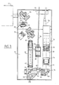
- the machine comprises a support 10 for an object to be treated, for example an integrated circuit, towards which the objective 12 of a microscope carried by a rigid stage 14 is oriented. , non-deformable and insensitive to vibrations, which is for example horizontal and is supported by a metal frame 16, a display screen 18 connected to the output of the observation path carried by the plate 14, a control panel 20 for adjustment focusing the laser beam on the object to be tracked and displacements of the object's support, and a control panel 22 comprising various means for controlling and adjusting the laser.
- a support 10 for an object to be treated for example an integrated circuit
- the objective 12 of a microscope carried by a rigid stage 14 is oriented.
- non-deformable and insensitive to vibrations which is for example horizontal and is supported by a metal frame 16
- a display screen 18 connected to the output of the observation path carried by the plate 14
- a control panel 20 for adjustment focusing the laser beam on the object to be tracked and displacements of the object's support
- a control panel 22 comprising
- the laser 24, of which only a part is shown in FIGS. 2 and 3, is a continuous Argon laser, having a multi-line optical power of the order of several Watts and a spectral band of 450 to 525 nm approximately.
- the emitted laser beam meets a first deflection mirror 26 which reflects the laser beam at right angles to an optical isolator 28 comprising a polarizing cube 30 and a quarter-wave plate 32 which prevents the reinjection of the laser energy into the exit cavity of the laser 24 during the passage of the point of impact of the laser beam over a highly reflective part, such as aluminum, from the surface of the object to be treated. This avoids destabilization of the laser 24.
- the laser beam meets another fixed deflection mirror 34, which reflects the laser beam at right angles to a deflection mirror 36 reflecting the laser beam at right angles to an afocal magnification device 38 comprising an input lens 40 movable in translation for focusing the laser beam and an output lens 42.
- This device 38 ensures an expansion of the laser beam with a linear magnification ratio of the order of three for example, which is compatible with the diameter of the entrance pupil of the microscope objective 12.
- the laser beam has a diameter, at the outlet of the device 38, which corresponds substantially to that of the entrance pupil of the objective 12, so that the laser beam is not diaphragmed by the objective 12, which would result in a loss of energy, and not be concentrated on a narrow area of the entrance pupil of the microscope, which would result in the risk of destruction of the lenses.
- this afocal magnification device 38 also makes it possible to compensate for the divergence of the laser beam for working in parallel light.
- the parallel laser beam leaving the device 38 crosses a dichroic blade 44 oriented at 45 ° and carried by a block 46 on which is mounted a deflection mirror 48 reflecting the laser beam at right angles to the entrance pupil of the lens 12 microscope, which is oriented towards the support 10 of the object to be treated.
- the microscope objective 12 is carried by a rotary turret 50 comprising several objectives having different magnifications.
- the deflection mirror 26 is optically conjugated with the surface of the object to be treated and allows, by two angular rotations, the deflection of the laser beam and the adjustment of its impact at the center of the pupil.
- the mirror 36 can be associated with motorization means, when it is necessary to scan the point of impact of the laser beam on the surface of the object to be tracked.
- the first deflection mirror 26 and the optical isolator 28 are carried by a plate 52 which is not integral with the plate 14 carrying the deflection mirrors 34 and 36, the afocal device 38 and the block 46 on which is mounted the turret 50 carrying the objectives of the microscope.
- the microscope can thus be made mobile relative to the laser.
- the plate 14 is associated with damping devices filtering the vibrations liable to be transmitted to the plate, for example the vibrations caused by the cooling water circuit of the laser 24.
- the various aforementioned optical means constitute the transmission path of the laser beam on the plate 14.
- This also carries a lighting track comprising a bundle 54 of optical fibers, one end of which is connected to a lighting source of any type, for example an incandescent lamp, external to the plate 14 and to the plate 52, and the other end of which is connected to a device 56 mounted on the plate 14 and comprising a plate 58 having a central orifice for the passage of the light beam leaving the optical fibers 56, to limit stray light, and a field diaphragm 60 which is optically conjugated with the surface of the object to be treated.
- a lighting track comprising a bundle 54 of optical fibers, one end of which is connected to a lighting source of any type, for example an incandescent lamp, external to the plate 14 and to the plate 52, and the other end of which is connected to a device 56 mounted on the plate 14 and comprising a plate 58 having a central orifice for the passage of the light beam leaving the optical fibers 56, to limit stray light, and a field diaphragm 60 which is optically
- the diaphragm light beam leaving the device 56 first crosses an optical doublet 62 carried by the aforementioned block 46, then is reflected at right angles on a semi-transparent plate 64 in the direction of the dichroic plate 44, and is finally reflected by this blade 44 on the aforementioned return mirror 48.
- the end of the fiber optic bundle 54, the device 56, the doublet 62, the semi-transparent plate 64, the dichroic plate 44 and the return mirror 48 associated with the microscope objective 12 constitute the lighting path, carried by the plate 14, of the object to be treated.
- An observation path is provided on the stage 14 and comprises, in addition to the microscope objective 12, the mirror 48 and the dichroic plate 44, the semi-transparent plate 64 which the beam passes through.
- luminous, a compact telephoto lens comprising converging lenses 66 and a deflection mirror 68 carried by a block 70 and divergent lenses 72 carried by another block 74 oriented towards the input objective of a CCD matrix camera 76 (charge transfer) fixed on the plate 14 and the output 78 of which is connected to the display screen 18 .
- Optical filters 80 and 82 are interposed between the input of the camera 76 and the output of the telephoto lens, to attenuate the image of the impact of the laser beam on the object to be trapped and allow viewing by the camera 76 and l screen 18 both the surface of the object to be treated and the impact of the laser beam on this surface.
- a prism can also be placed on the display channel of the plate 14 between the optical filter 80 and the output of the telephoto lens, to modify the direction of movement of the image on the display screen 18.
- the various optical components carried by the plate 14 are removably mounted thereon by screws and are associated with very precise mechanical positioning means, for example pins carried by the plate 14 and received in cavities of the supports of the components, to allow disassembly of these components and their replacement without the need to make new optical adjustments.
- the lighting path carried by the plate 14 has the advantage of a reduced bulk.
- the lighting light source is external to the plate 14, does not thermally influence the optical components mounted on this plate, and can be changed without it being necessary to make new adjustments. This also gives uniform illumination of the entire field of observation on the surface of the object to be tracked.
- the support 10 of the object to be treated comprises (FIGS. 2 and 4) an upper plate 84 on which the object to be treated is fixed by vacuum.
- This upper plate 84 is connected by vertical uprights 86 to a lower plate 88 associated with piezoelectric motors allowing fine adjustment of focus by vertical displacement of the plates 88 and 84, for example over a stroke of 100 microns with an accuracy of 0, 1 micron.
- All of the plates 84 and 88 are carried by a crown 90 rotating around the vertical axis, by manual or motorized control, to allow the surface of the object to be treated to be oriented with respect to two perpendicular horizontal axes of movement.
- the crown 90 is itself carried by a first table 92, movable along a horizontal axis by a stepping electric motor, and this table 92 is itself carried by a table 94 movable in translation along a perpendicular horizontal axis cular to the first by another electric stepper motor.
- These two motors have, for example, a stroke of 100 or 150 mm, with a minimum displacement of 0.1 micrometer.
- the set of tables 92 and 94 is carried by a column 96 which can be moved vertically by manual control, for rough adjustment of focus, with an accuracy of 1 micrometer over a stroke of approximately 12 to 15 mm.
- the electric stepping motors for moving tables 92 and 94 can be controlled from table 20 ( Figure 1) for example by means of a ball joint lever 98, movable in two perpendicular directions corresponding to the two directions of movement of tables 92 and 94.
- the table 20 also includes means 100 for displaying the coordinates on these two axes of a point on the surface of the object to be tracked, and a rotary button 102 for controlling the piezoelectric motors for fine adjustment of focus. .
- the machine according to the invention operates as follows.
- the object to be treated is placed on the upper plate 84 of the support 10 and is held in position by vacuum, which makes it possible inter alia to at least partially correct the flatness defects of the supports of thin layers.
- a lens 12 is selected having a magnification suitable for the envisaged intervention.
- the operation of the lighting path and the observation path makes it possible to search, on the display screen 18, for the particular area to be tracked on the surface of the object.
- the microscope objective 12 has a magnification of 50
- the diagonal of the field of view on the surface of the object to be treated is 135 micrometers
- the magnification ratio of the image on the display screen 18 is 2,000.
- a reticle 20 can be provided on the lighting path, being slightly defocused, so as to materialize the optical axis on the image while allowing to visualize what is behind the reticle.
- the laser 24 is started up and produces a laser beam at a relatively high power level ( of the order of 1 to 2 Watts) for a limited period of the order of one second for example, to initiate a thermochemical reaction between the thin layer to be cut and the underlying layer.
- the power of the laser beam is then reduced and, by controlling the electric motor, displacement of a table 92 or 94, the point of impact of the laser beam is displaced to make the desired cut.
- the diameter of the point of impact of the laser beam on the surface of the object to be treated is, with a magnification objective 50, of the order of 1 micrometer maximum.
- the depth of field is of the order of plus or minus 0.5 micrometer, the free working distance between the end of the objective 12 and the surface of the object to be treated being of the order of 8 mm.
- magnification ratio of the image on the display screen 18 is of the order of 4,000.
- the machine according to the invention can therefore make a fine cut of the connection connections on an integrated circuit, for example for the correction of micro-faults or short-circuits. It can also cut a metallization layer around a contact hole and it also allows detection and localization of sensitive points of a circuit supplied in the vicinity of its marginal voltage, by scanning with a laser beam. Excitation of critical points in the circuit can cause detectable logic errors, which makes it possible to locate these sensitive points.
- This machine also allows interventions in microchemistry, by means of local reactions induced by the laser beam.
- the plate 14 carrying most of the optical components of the machine is fixed, while the support of the object to be treated is mobile.
- this plate can be made mobile if necessary.
- a microprocessor can be coupled to the machine to automatically control, according to predetermined sequences, the movements of the object to be treated relative to the selected microscope objective and adjust the power level of the laser.
- An automatic focusing device of a conventional type, can also be used to continuously adjust the focusing of the laser beam on the surface of the object to be tracked and thus correct focusing errors caused for example by displacements of the object to be treated, defects in the flatness of its surface, etc.
Abstract
Machine à microfaisceau laser d'intervention sur des objets à couches minces, comprenant une platine (14) rigide et indéformable sur laquelle sont montés des composants optiques définissant une voie (34, 36, 38, 46) de transmission du faisceau laser, une voie (54, 56, 46) d'éclairage et une voie (70, 74, 76) d'observation. L'invention permet notamment des micro-interventions sur des circuits intégrés et des objets à couches minces.Laser microbeam intervention machine for thin film objects, comprising a rigid and non-deformable plate (14) on which are mounted optical components defining a path (34, 36, 38, 46) for transmitting the laser beam, a path (54, 56, 46) of lighting and a way (70, 74, 76) of observation. The invention allows in particular micro-interventions on integrated circuits and thin film objects.
Description
L'invention concerne une machine à microfaisceau laser d'intervention sur des objets à couches minces de matériau, par exemple pour leur découpe.The invention relates to a laser microbeam intervention machine for objects with thin layers of material, for example for cutting them.
On connaît déjà des machines de ce type, qui utilisent en général un laser à impulsions. Ces machines sont difficilement utilisables pour des interventions sur des circuits intégrés et sur des couches minces, par exemple des couches magnétiques formées sur les têtes magnétiques des magnétoscopes ou des lecteurs de disques ou de disquettes informatiques, les intervalles de temps entre les impulsions du laser se traduisant par un refroidissement de la couche de matériau sur laquelle on opère et ne permettant pas une rapidité d'exécution et une finesse de découpe intéressantes.Machines of this type are already known, which generally use a pulsed laser. These machines are difficult to use for interventions on integrated circuits and on thin layers, for example magnetic layers formed on the magnetic heads of video recorders or disk drives or computer diskettes, the time intervals between the laser pulses resulting in a cooling of the layer of material on which one operates and not allowing rapid execution and interesting cutting finesse.
On a déjà proposé d'utiliser dans ces machines un laser continu, du type à Argon, qui est couplé à un circuit optique comprenant un microscope pour permettre de focaliser le faisceau laser avec un diamètre de l'ordre du micromètre sur la surface de l'objet à traîter. Il s'agit cependant d'un appareil de laboratoire, qui nécessite des réglages extrêmement fins et délicats, et qui n'est pas utilisable industriellement.It has already been proposed to use in these machines a continuous laser, of the Argon type, which is coupled to an optical circuit comprising a microscope to enable the laser beam to be focused with a diameter of the order of a micrometer on the surface of the object to be treated. However, it is a laboratory device, which requires extremely fine and delicate adjustments, and which cannot be used industrially.
L'invention a pour objet une machine à microfaisceau laser pour intervention sur des objets à couches minces de matériau, qui puisse être utilisée de façon industrielle, qui soit automatisable et qui permette une observation précise de l'action du microfaisceau laser sur l'objet à traîter.The subject of the invention is a laser micro-beam machine for working on objects with thin layers of material, which can be used industrially, which can be automated and which allows precise observation of the action of the laser micro-beam on the object. treat.
L'invention a encore pour objet une machine de ce type, qui puisse être utilisée non seulement pour des interventions précises sur des circuits intégrés, par exemple pour la correction de microdéfauts, mais également pour une micro-analyse, une réparation et une reconfiguration de circuits intégrés et d'objet divers comprenant des couches minces de matériaux utilisés en micro-électronique par exemple.The invention also relates to a machine of this type, which can be used not only for precise interventions on integrated circuits, for example for the correction of micro-faults, but also for micro-analysis, repair and reconfiguration of integrated circuits and various objects comprising thin layers of materials used in microelectronics for example.
L'invention propose à cet effet une machine à microfaisceau laser d'intervention sur des objets à couches minces de matériau, comprenant un laser continu couplé à un microscope permettant de focaliser le faisceau laser en un point particulier de l'objet et d'observer le point d'impact du faisceau laser sur l'objet, caractérisée en ce qu'elle comprend une platine rigide, indéformable et insensible aux vibrations, placée à la sortie du laser et sur laquelle sont fixés amoviblement au moins un objectif de microscope et des composants optiques définissant trois voies optiques qui sont indépendantes l'une de l'autre et qui comportent des moyens indépendants de réglage, ces trois voies comprenant une voie de transmission du faisceau laser jusqu'à l'objectif du microscope orienté vers l'objet, une voie d'éclairage transmettant un faisceau lumineux vers ledit objectif de microscope, et une voie d'observation reliant l'objectif de microscope à des moyens électroniques de visualisation de la zone traîtée de l'objet et du point d'impact du faisceau laser sur cette zone.The invention proposes for this purpose a laser microbeam intervention machine for objects with thin layers of material, comprising a continuous laser coupled to a microscope making it possible to focus the laser beam at a particular point on the object and to observe the point of impact of the laser beam on the object, characterized in that it comprises a rigid plate, non-deformable and insensitive to vibrations, placed at the exit of the laser and to which are removably fixed at least one microscope objective and optical components defining three optical channels which are independent of each other and which include independent adjustment means, these three channels comprising a laser beam transmission channel up to the objective of the microscope oriented towards the object, a lighting channel transmitting a light beam towards said microscope objective, and an observation channel connecting the microscope objective to electronic means for visualizing the area line of the object and the point of impact of the laser beam on this area.
Il est ainsi possible, grâce à ces trois voies optiques indépendantes et à leurs moyens de réglage, de traîter une couche mince de matériau sur un object avec un faisceau laser dont le diamètre sur la surface de l'objet est de l'ordre du micromètre, et simultanément d'observer de façon continue, sans risques, l'action du faiceau laser sur la surface de l'objet à traîter pour guider le déplacement de ce faisceau sur toute la zone d'intervention.It is thus possible, thanks to these three independent optical channels and their means of adjustment, to trace a thin layer of material on an object with a laser beam whose diameter on the surface of the object is of the order of a micrometer , and simultaneously to observe continuously, without risks, the action of the laser beam on the surface of the object to be tracked to guide the movement of this beam over the entire intervention area.
Selon une autre caractéristique de l'invention, la platine précitée comprend des moyens mécaniques de positionnement précis des composants optiques, permettant de les démonter et de les remplacer sans modification des réglages optiques.According to another characteristic of the invention, the aforementioned plate comprises mechanical means for precise positioning of the optical components, making it possible to disassemble and replace them without modifying the optical settings.
On peut ainsi, très facilement et sans perte de temps, adapter la machine à une intervention d'une type déterminé.It is thus very easy and without loss of time to adapt the machine to an intervention of a specific type.
Selon encore une autre caractéristique de l'invention, la voie d'observation sur la platine précitée comprend une caméra matricielle du type C.C.D., dont la sortie est reliée est reliée à un écran de visualisation indépendant de la platine et dont l'entrée est reliée à l'objectif de microscope par des filtres d'atténuation de l'image du point d'impact du faisceau laser, et par des moyens optiques d'agrandissement d'image.According to yet another characteristic of the invention, the observation path on the aforementioned plate comprises a matrix camera of the CCD type, the output of which is connected is connected to a display screen independent of the plate and the input of which is connected to the microscope objective by filters for attenuating the image of the point of impact of the laser beam, and by optical means for enlarging the image.
Le personnel peut ainsi observer de façon continue l'objet traîté et l'impact réel du faisceau laser. Par ailleurs, le positionnement du faisceau laser sur l'objet à traîter peut être assuré avec une précision de l'ordre de 0,2 micromètre.Staff can thus continuously observe the object being treated and the real impact of the laser beam. Furthermore, the positioning of the laser beam on the object to be treated can be ensured with an accuracy of the order of 0.2 micrometer.
Selon encore une autre caractéristique de l'invention, la voie de transmission du faisceau laser sur la platine comprend un premier miroir de renvoi suivi d'un bloc optique afocal de grandissement du faisceau laser, une lame dichroïque traversée par le faisceau laser, et un autre miroir de renvoi vers l'objectif de microscope.According to yet another characteristic of the invention, the transmission path of the laser beam on the stage comprises a first deflection mirror followed by an afocal optical block for magnification of the laser beam, a dichroic plate traversed by the laser beam, and a another mirror for returning to the microscope objective.
Le premier miroir de renvoi est conjugué optiquement de la pupille d'entrée de l'objectif de microscope. Son réglage n'influence donc pas la position du faisceau laser par rapport au centre de la pupille mais uniquement la position du point d'impact du faisceau laser focalisé sur l'objet à traîter.The first deflection mirror is optically conjugated with the pupil of the microscope objective. Its adjustment therefore does not influence the position of the laser beam relative to the center of the pupil but only the position of the point of impact of the laser beam focused on the object to be trailed.
Avantageusement, ce premier miroir est motorisé, pour assurer par exemple un balayage du point d'impact du faisceau laser sur la surface de l'objet.Advantageously, this first mirror is motorized, for example for scanning the point of impact of the laser beam on the surface of the object.
Selon une autre caractéristique de l'invention, cette voie de transmission du faisceau laser sur la platine est reliée à la sortie du laser par un autre miroir de renvoi et un isolateur optique, empêchant une réinjection du faisceau laser par la sortie du laser.According to another characteristic of the invention, this transmission path of the laser beam on the stage is connected to the laser output by another deflection mirror and an optical isolator, preventing reinjection of the laser beam by the laser output.
Il se peut en effet que la surface de l'objet à traîter comprenne une couche très réfléchissante, par exemple en aluminium. L'isolateur optique, qui empêche la réinjection du faisceau laser réfléchi, évite ainsi une déstabilisation du laser.It may indeed be that the surface of the object to be treated comprises a highly reflective layer, for example of aluminum. The optical isolator, which prevents the reinjection of the reflected laser beam, thus avoids destabilization of the laser.
Avantageusement, le miroir de renvoi associé à l'isolateur optique est conjugué optiquement de la zone visée de l'objet, pour permettre le réglage de l'impact du faisceau laser au centre de la pupille d'entrée du microscope.Advantageously, the deflection mirror associated with the optical isolator is optically conjugated with the targeted area of the object, to allow adjustment of the impact of the laser beam at the center of the entrance pupil of the microscope.
Les réglages du point d'impact du faisceau laser sur la surface de l'objet à traîter et du point d'impact du faisceau laser sur la pupille d'entrée de l'objectif du microscope sont donc indépendants l'un de l'autre.The settings for the point of impact of the laser beam on the surface of the object to be trapped and the point of impact of the laser beam on the entrance pupil of the microscope objective are therefore independent of each other. .
Selon une autre caractéristique de l'invention, la voie d'éclairage portée par la platine comprend un faisceau de fibres optiques dont une extrémité est raccordée à une source lumineuse extérieure à la platine et dont l'autre extrémité est conjuguée optiquement de la pupille d'entrée de l'objectif de microscope, ainsi qu'une lame semi-transparente réfléchissant, en direction de la lame dichroïque traversée par le faisceau laser, le faisceau lumineux sortant des fibres optiques.According to another characteristic of the invention, the lighting path carried by the plate comprises a bundle of optical fibers, one end of which is connected to a light source external to the plate and the other end of which is optically conjugated with the pupil d entry of the microscope objective, as well as a semi-transparent reflecting plate, in the direction of the dichroic plate crossed by the laser beam, the light beam leaving the optical fibers.
La lame dichroïque de la voie de transmission du faisceau laser, qui est traversée par le faisceau laser et qui réfléchit le faisceau lumineux d'éclairage, sert donc d'interface entre les voies de transmission du faisceau laser et d'éclairage.The dichroic blade of the laser beam transmission path, which is crossed by the laser beam and which reflects the lighting light beam, therefore serves as an interface between the laser beam transmission and lighting paths.
Avantageusement, la lame semi-transparente précitée est placée à l'entrée de la voie d'observation et est traversée par le faisceau lumineux réfléchi par l'objet et dirigé vers la caméra matricielle C.C.D. de la voie d'observation.Advantageously, the aforementioned semi-transparent plate is placed at the entrance to the observation path and is crossed by the light beam reflected by the object and directed towards the matrix camera C.C.D. from the observation path.
L'invention prévoit également que l'objet à traîter est monté sur un support associé à des moyens de déplacement dans trois directions perpendiculaires, dont deux sont parallèles à la platine, et que le support de l'objet est mobile en rotation autour de son axe de déplacement perpendiculaire à la platine.The invention also provides that the object to be treated is mounted on a support associated with displacement means in three perpendicular directions, two of which are parallel to the plate, and that the object support is movable in rotation about its axis of movement perpendicular to the plate.
Selon un mode de réalisation préféré de l'invention, des moteurs électriques pas à pas assurent le déplacement du support du l'objet dans les deux directions parallèles à la platine tandis que les moyens de déplacement du support dans la troisième direction comprennent des moyens de réglage manuel, ainsi que des moteurs piézoélectriques assurant un réglage fin de la position de l'objet à traîter.According to a preferred embodiment of the invention, electric stepping motors ensure the movement of the support of the object in the two directions parallel to the plate while the means of movement of the support in the third direction comprise means of manual adjustment, as well as piezoelectric motors ensuring fine adjustment of the position of the object to be treated.
Ces différents moyens moteur peuvent être commandés automatiquement par un microprocesseur, dans le cas d'interventions répétitives sur des objets identiques.These different motor means can be controlled automatically by a microprocessor, in the case of repetitive interventions on identical objects.
L'invention sera mieux comprise et d'autres détails, caractéristiques et avantages de celle-ci apparaîtront au cours de la description qui va suivre, faite à titre d'exemple en référénce aux dessins anexés et dans lesquels:
- - la figure 1 est une vue schématique d'une machine selon l'invention;
- - la figure 2 est une vue schématique partielle en perspective de cette machine;
- - la figure 3 est une vue en plan de la platine optique de la machine;
- - la figure 4 est une vue schématique en coupe partielle, selon la ligne IV-IV de la figure 3.
- - Figure 1 is a schematic view of a machine according to the invention;
- - Figure 2 is a partial schematic perspective view of this machine;
- - Figure 3 is a plan view of the optical stage of the machine;
- FIG. 4 is a schematic view in partial section, along the line IV-IV of FIG. 3.
Comme on le voit schématiquement en figure 1, la machine selon l'invention comprend un support 10 d'un objet à traîter, par exemple un circuit intégré, vers lequel est orienté l'objectif 12 d'un microscope porté par une platine 14 rigide, indéformable et insensible aux vibrations, qui est par exemple horizontale et est supportée par un bâti métallique 16, un écran de visualisation 18 relié à la sortie de la voie d'observation portée par la platine 14, un tableau de commande 20 pour le réglage de la focalisation du faisceau laser sur l'objet à traîter et des déplacements du support de l'objet, et un tableau de commande 22 comprenant divers moyens de commande et de réglage du laser.As can be seen diagrammatically in FIG. 1, the machine according to the invention comprises a
Le laser 24, dont seule une partie est représentée dans les figures 2 et 3 est un laser continu à Argon, ayant une puissance optique multiraies de l'ordre de plusieurs Watts et une bande spectrale de 450 à 525 nm environ.The
Le faisceau laser émis rencontre un premier miroir de renvoi 26 qui réfléchit le faisceau laser à angle droit vers un isolateur optique 28 comprenant un cube polarisant 30 et une lame quart d'onde 32 qui empêche la réinjection de l'énergie laser dans la cavité de sortie du laser 24 lors du passage du point d'impact du faisceau laser sur une partie très réfléchissante, telle que de l'aluminium, de la surface de l'objet à traîter. On évite ainsi une déstabilisation du laser 24.The emitted laser beam meets a
A la sortie de l'isolateur optique 28, le faisceau laser rencontre un autre miroir de renvoi 34 fixe, qui réfléchit le faisceau laser à angle droit vers un miroir de renvoi 36 refléchissant le faisceau laser à angle droit vers un dispositif afocal de grandissement 38 comprenant un lentille d'entrée 40 mobile en translation pour la focalisation du faisceau laser et une lentille de sortie 42. Ce dispositif 38 assure un expansion du faisceau laser avec un rapport de grandissement linéaire de l'ordre de trois par exemple, qui est compatible avec le diamètre de la pupille d'entrée de l'objectif 12 de microscope. Ainsi, le faisceau laser a un diamètre, à la sortie du dispositif 38, qui correspond sensiblementà celui de la pupille d'entrée de l'objectif 12, de façon à ce que le faisceau laser ne soit pas diaphragmé par l'objectif 12, ce qui se traduirait par une perte d'énergie, et ne soit pas concentré sur une zone étroite de la pupille d'entrée du microscope, ce qui se traduirait par des risques de destruction des lentilles.At the output of the
Par ailleurs, ce dispositif afocal de grandissement 38 permet également de compenser la divergence du faisceau laser pour travailler en lumière parallèle.Furthermore, this
Le faisceau laser parallèle sortant du dispositif 38 traverse une lame dichroïque 44 orientée à 45 ° et portée par un bloc 46 sur lequel est monté un miroir de renvoi 48 réfléchissant le faisceau laser à angle droit sur la pupille d'entrée de l'objectif 12 de microscope, qui est orienté vers le support 10 de l'objet à traîter. L'objectif 12 de microscope est porté par une tourelle rotative 50 comprenant plusieurs objectifs ayant des grandissements différents.The parallel laser beam leaving the
Comme indiqué dans ce qui précède, le miroir de renvoi 26 est conjugué optiquement de la surface de l'objet à traîter et permet, par deux rotations angulaires, le renvoi du faisceau laser et le réglage de son impact au centre de la pupille d'entrée de l'objectif 12 de microscope tandis que le miroir de renvoi 36 est conjugué optiquement, par l'intermédiaire du dispositif 38, de la pupille d'entrée de l'objectif de microscope 12, de sorte que son réglage n'influence pas la position de l'impact du faisceau laser par rapport au centre de la pupille d'entrée de l'objectif 12, mais uniquement la position du point d'impact du faisceau laser focalisé sur l'objet à traîter. Ces deux réglages sont donc rendus indépendants. En outre, le miroir 36 peut être associé à des moyens de motorisation, lorsqu'il est nécessaire de réaliser un balayage du point d'impact du faisceau laser sur la surface de l'objet à traîter.As indicated in the foregoing, the
De préférence, le premier miroir de renvoi 26 et l'isolateur optique 28 sont portés par une plaque 52 qui n'est pas solidaire de la platine 14 portant les miroirs de renvoi 34 et 36, le dispositif afocal 38 et le bloc 46 sur lequel est montée la tourelle 50 portant les objectifs du microscope. Le microscope peut ainsi être rendu mobile par rapport au laser. La platine 14 est associée à des dispositifs amortisseurs filtrant les vibrations susceptibles d'être transmises à la platine, par exemple les vibrations provoquées par le circuit d'eau de refroidissement du laser 24.Preferably, the
Les différents moyens optiques précités constituent la voie de transmission du faisceau laser sur la platine 14.The various aforementioned optical means constitute the transmission path of the laser beam on the
Celle-ci porte également une voie d'éclairage comprenant un faisceau 54 de fibres optiques dont une extrémité est raccordée à une source d'éclairage d'un type quelconque, par exemple une lampe à incandescence, extérieure à la platine 14 et à la plaque 52, et dont l'autre extrémité est raccordée à un dispositif 56 monté sur la platine 14 et comportant une plaque 58 présentant un orifice central de passage du faisceau lumineux sortant des fibres optiques 56, pour limiter la lumière parasite, et un diaphragme de champe 60 qui est conjugué optiquement avec la surface de l'objet à traîter.This also carries a lighting track comprising a
Le faisceau lumineux diaphragmé sortant du dispositif 56 traverse tout d'abord un doublet optique 62 porté par le bloc 46 précité, puis est réfléchi à angle droit sur une lame semi-transparente 64 en direction de la lame dichroïque 44, et est finalement réfléchi par cette lame 44 sur le miroir de renvoi 48 précité.The diaphragm light beam leaving the
L'extrémité du faisceau de fibres optiques 54, le dispositif 56, le doublet 62, la lame semi-transparente 64, la lame dichroïque 44 et le miroir de renvoi 48 associé à l'objectif 12 de microscope constituent la voie d'éclairage, portée par la platine 14, de l'objet à traîter.The end of the fiber
Une voie d'observation, indépendante des deux voies précédentes, est prévue sur la platine 14 et comprend, outre l'objectif 12 de microscope, le miroir 48 et la lame dichroïque 44, la lame semi-transparente 64 que est traversée par le faisceau lumineux, un téléobjectif compact comprenant des lentilles 66 convergentes et un miroir de renvoi 68 porté par un bloc 70 et des lentilles 72 divergentes portées par un autre bloc 74 orienté vers l'objectif d'entrée d'une caméra matricielle C.C.D. 76 (à transfert de charge) fixée sur la platine 14 et dont la sortie 78 est reliée à l'écran de visualisation 18.An observation path, independent of the two previous paths, is provided on the
Des filtres optiques 80 et 82 sont interposés entre l'entrée de la caméra 76 et la sortie du téléobjectif, pour atténuer l'image de l'impact du faisceau laser sur l'objet à traîter et permettre de visualiser par la caméra 76 et l'écran 18 aussi bien la surface de l'objet à traîter que l'impact du faisceau laser sur cette surface.
Un prisme peut également être placé sur la voie de visualisation de la platine 14 entre le filtre optique 80 et la sortie du téléobjectif, pour modifier sur l'écran de visualisation 18 le sens de déplacement de l'image.A prism can also be placed on the display channel of the
Les différents composants optiques portés par la platine 14 sont montés de façon amovible sur celle-ci par des vis et sont associés à des moyens de positionnement mécanique très précis, par exemple des pions portés par la platine 14 et reçus dans des cavités des supports des composants, pour permettre le démontage de ces composants et leur remplacement sans qu'il soit nécessaire de procéder à des nouveaux réglages optiques. La voie d'éclairage portée par la platine 14 présente l'avantage d'un encombrement réduit. La source de lumière d'éclairage est extérieure à la platine 14, n'influence pas thermiquement les composants optiques montés sur cette platine, et peut être changée sans qu'il soit nécessaire de procéder à des nouveaux réglages. On obtient également ainsi un éclairage uniforme de tout le champ d'observation sur la surface de l'objet à traîter.The various optical components carried by the
Le support 10 de l'objet à traîter comprend (figures 2 et 4) une plaque supérieure 84 sur laquelle l'objet à traîter est fixé par dépression.The
Cette plaque supérieure 84 est reliée par des montants verticaux 86 à une plaque inférieure 88 associée à des moteurs piézoélectriques permettant un réglage fin de focalisation par déplacement vertical des plaques 88 et 84, par exemple sur une course de 100 microns avec une précision de 0,1 micron.This
L'ensemble des plaques 84 et 88 est porté par une couronne 90 rotative autour de l'axe vertical, par commande manuelle ou motorisée, pour permettre d'orienter la surface de l'objet à traîter par rapport à deux axes de déplacement horizontaux perpendiculaires. La couronne 90 est elle-même portée par une première table 92, déplacable le long d'un axe horizontal par un moteur électrique pas à pas, et cette table 92 est elle-même portée par une table 94 déplacable en translation le long d'un axe horizontal perpendi culaire au premier par un autre moteur électrique pas à pas. Ces deux moteurs ont par exemple une course de 100 ou 150 mm, avec un déplacement minimal de 0,1 micromètre.All of the
L'ensemble des tables 92 et 94 est porté par une colonne 96 déplacable verticalement par commande manuelle, pour un réglage grossier de focalisation, avec une précision de 1 micromètre sur une course de 12 à 15 mm environ.The set of tables 92 and 94 is carried by a
Les moteurs électriques pas à pas de déplacement des tables 92 et 94 peuvent être commandées à partir du tableau 20 (figure 1) par exemple au moyen d'un levier à rotule 98, déplacable dans deux directions perpendiculaires correspondant aux deux directions de déplacement des tables 92 et 94. Le tableau 20 comprend également des moyens 100 d'affichage des coordonnées sur ces deux axes d'un point de la surface de l'objet à traîter, et un bouton rotatif 102 de commande des moteurs piézoélectriques de réglage fin de focalisation.The electric stepping motors for moving tables 92 and 94 can be controlled from table 20 (Figure 1) for example by means of a ball
La machine selon l'invention fonctionne de la façon suivante.The machine according to the invention operates as follows.
L'objet à traîter est placé sur la plaque supérieure 84 du support 10 et est maintenu en position par dépression, ce qui permet entre autres de corriger au moins partiellement les défauts de planéité des supports de couches minces. Par rotation de la tourelle 50, on sélectionne un objectif 12 ayant un grossissement approprié à l'intervention envisagée.The object to be treated is placed on the
Le fonctionnement de la voie d'éclairage et de la voie d'observation permet de rechercher, sur l'écran de visualisation 18, la zone particulière à traîter sur la surface de l'objet. Lorsque l'objectif 12 de microscope a un grossissement de 50, la diagonale du champ d'observation sur la surface de l'objet à traîter est de 135 micromètres, tandis que le rapport de grandissement de l'image sur l'écran de visualisation 18 est de 2 000.The operation of the lighting path and the observation path makes it possible to search, on the
Un réticule 20 peut être prévu sur la voie d'éclairage, en étant légèrement défocalisé, de façon à matérialiser l'axe optique sur l'image tout en permettant de visualiser ce qui se trouver derrière le réticule. Lorsque l'axe optique est correctement positionné sur la surface de l'objet à traîter, par exemple au bord d'une couche mince à découper, le laser 24 est mis en route et produit un faisceau laser à un niveau de puissance relativement élevée (de l'ordre de 1 à 2 Watts) pendant une durée limitée de l'ordre d'une seconde par exemple, pour amorcer une réaction thermochimique entre la couche mince à découper et la couche sous-jacente. On réduit ensuite la puissance du faisceau laser et, par commande du moteur électrique de déplacement d'une table 92 ou 94, on déplace le point d'impact du faisceau laser pour réaliser la découpe voulue.A
Le diamètre du point d'impact du faisceau laser sur la surface de l'objet à traîter est, avec un objectif de grossissement 50, de l'ordre de 1 micromètre au maximum. La profondeur de champ est de l'ordre de plus ou moins 0,5 micromètre, la distance libre de travail entre l'extrémité de l'objectif 12 et la surface de l'objet à traîter étant de l'ordre de 8 mm.The diameter of the point of impact of the laser beam on the surface of the object to be treated is, with a
On peut également utiliser un objectif de microscope ayant un grossissement supérieur, par exemple de 100. Dans ce cas, le diamètre du faisceau laser focalisé est inférieur à 1 micromètre, la profondeur de champ est de plus ou moins 0,2 micromètre et la distance libre de travail entre l'extrémité de l'objectif et la surface de l'objet à traîter de l'ordre de 0,3 mm. Le rapport d'agrandissement de l'image sur l'écran de visualisation 18 est de l'ordre de 4 000.It is also possible to use a microscope objective having a greater magnification, for example of 100. In this case, the diameter of the focused laser beam is less than 1 micrometer, the depth of field is more or less 0.2 micrometer and the distance free of work between the end of the objective and the surface of the object to be treated in the order of 0.3 mm. The magnification ratio of the image on the
La machine selon l'invention peut donc réaliser une découpe fine des connections de liaison sur un circuit intégré, par exemple pour la correction de microdéfauts ou de court-circuits. Elle peut également réaliser la découpe d'une couche de métallisation autour d'un trou de contact et elle permet également une détection et une localisation des points sensibles d'un circuit alimenté au voisinage de sa tension marginale, par balayage par un faisceau laser. L'excitation des points critiques du circuit peut provoquer des erreurs logiques détectables, ce qui permet de localiser ces points sensibles.The machine according to the invention can therefore make a fine cut of the connection connections on an integrated circuit, for example for the correction of micro-faults or short-circuits. It can also cut a metallization layer around a contact hole and it also allows detection and localization of sensitive points of a circuit supplied in the vicinity of its marginal voltage, by scanning with a laser beam. Excitation of critical points in the circuit can cause detectable logic errors, which makes it possible to locate these sensitive points.
Cette machine permet également des interventions en microchimie, au moyen de réactions locales induites par le faisceau laser.This machine also allows interventions in microchemistry, by means of local reactions induced by the laser beam.
Dans l'exemple de réalisation qui a été décrit, la platine 14 portant l'essentiel des composants optiques de la machine est fixe, tandis que le support de l'objet à traîter est mobile. On peut cependant rendre cette platine mobile si nécessaire.In the embodiment which has been described, the
Pour les tâches répétitives, un microprocesseur peut être couplé à la machine pour commander automatiquement, selon des séquences prédéterminées, les déplacements de l'objet à traîter par rapport à l'objectif de microscope sélectionné et régler le niveau de puissance du laser. Un dispositif de focalisation automatique, d'un type classique, peut aussi être utilisé pour régler en continu la focalisation du faisceau laser sur la surface de l'objet à traîter et corriger ainsi des défauts de focalisation causés par exemple par les déplacements de l'objet à traîter, des défauts de planéité de sa surface, etc....For repetitive tasks, a microprocessor can be coupled to the machine to automatically control, according to predetermined sequences, the movements of the object to be treated relative to the selected microscope objective and adjust the power level of the laser. An automatic focusing device, of a conventional type, can also be used to continuously adjust the focusing of the laser beam on the surface of the object to be tracked and thus correct focusing errors caused for example by displacements of the object to be treated, defects in the flatness of its surface, etc.
Claims (16)
Applications Claiming Priority (2)
| Application Number | Priority Date | Filing Date | Title |
|---|---|---|---|
| FR8618079 | 1986-12-23 | ||
| FR8618079A FR2608484B1 (en) | 1986-12-23 | 1986-12-23 | LASER MICRO-BEAM MACHINE FOR WORKING ON THIN-FILM MATERIAL OBJECTS |
Publications (2)
| Publication Number | Publication Date |
|---|---|
| EP0277444A1 true EP0277444A1 (en) | 1988-08-10 |
| EP0277444B1 EP0277444B1 (en) | 1991-10-02 |
Family
ID=9342235
Family Applications (1)
| Application Number | Title | Priority Date | Filing Date |
|---|---|---|---|
| EP87402961A Expired - Lifetime EP0277444B1 (en) | 1986-12-23 | 1987-12-22 | Micro laser beam machine for intervening at objects having thin layers of material |
Country Status (9)
| Country | Link |
|---|---|
| US (1) | US4825034A (en) |
| EP (1) | EP0277444B1 (en) |
| JP (1) | JPS63238988A (en) |
| KR (1) | KR880007163A (en) |
| DE (1) | DE3773484D1 (en) |
| ES (1) | ES2026934T3 (en) |
| FR (1) | FR2608484B1 (en) |
| IL (1) | IL84897A (en) |
| IN (1) | IN172171B (en) |
Cited By (1)
| Publication number | Priority date | Publication date | Assignee | Title |
|---|---|---|---|---|
| EP0367507A2 (en) * | 1988-10-31 | 1990-05-09 | Spectra-Physics, Inc. | A diode-pumped, solid state laser-based workstation for precision materials processing and machining |
Families Citing this family (19)
| Publication number | Priority date | Publication date | Assignee | Title |
|---|---|---|---|---|
| FR2639567B1 (en) * | 1988-11-25 | 1991-01-25 | France Etat | LASER MICRO-BEAM MACHINE FOR WORKING ON THIN FILM OBJECTS, PARTICULARLY FOR CHEMICAL ENGRAVING OR DEPOSITION OF MATERIAL IN THE PRESENCE OF A REACTIVE GAS |
| FR2657803A1 (en) * | 1990-02-02 | 1991-08-09 | Bertin & Cie | LASER MICRO-BEAM MACHINE FOR WORKING ON THIN-FILM OBJECTS, SUCH AS INTEGRATED CIRCUITS. |
| DE69112272T2 (en) * | 1990-05-21 | 1996-02-01 | Ntn Toyo Bearing Co Ltd | Method and device for laser processing. |
| IT1240515B (en) * | 1990-07-27 | 1993-12-17 | Prima Ind Spa | ADJUSTMENT DEVICE TO ALIGN A LASER RADIUS ACCORDING TO A PERFORMANCE REFERENCE LINE |
| US5464960A (en) * | 1993-01-12 | 1995-11-07 | Iatrotech, Inc. | Laser calibration device |
| US5416821A (en) * | 1993-05-10 | 1995-05-16 | Trw Inc. | Grid formed with a silicon substrate |
| US5585016A (en) * | 1993-07-20 | 1996-12-17 | Integrated Device Technology, Inc. | Laser patterned C-V dot |
| JP3399590B2 (en) * | 1993-08-04 | 2003-04-21 | 富士通株式会社 | Wiring cutting device |
| US5872051A (en) * | 1995-08-02 | 1999-02-16 | International Business Machines Corporation | Process for transferring material to semiconductor chip conductive pads using a transfer substrate |
| US6472671B1 (en) * | 2000-02-09 | 2002-10-29 | Jean I. Montagu | Quantified fluorescence microscopy |
| US6794424B2 (en) * | 2001-12-04 | 2004-09-21 | Agilent Technologies, Inc. | Devices for calibrating optical scanners and methods of using the same |
| US20040094526A1 (en) * | 2002-11-15 | 2004-05-20 | Mccoy Edward D. | Cutting laser beam nozzle assembly |
| US7534561B2 (en) | 2003-04-02 | 2009-05-19 | Agilent Technologies, Inc. | Nucleic acid array in situ fabrication methods and arrays produced using the same |
| DE102004063692B3 (en) * | 2004-12-28 | 2006-05-11 | Georg-August-Universität Göttingen | Positioning device for moving objects along a carriage and having deflection elements for deflecting laser beams |
| DE102005059650B4 (en) * | 2005-12-14 | 2011-08-18 | Leica Microsystems CMS GmbH, 35578 | Mounting device for multiple lasers and microscope |
| DE102005059649B4 (en) * | 2005-12-14 | 2017-09-07 | Leica Microsystems Cms Gmbh | Device for mounting for several lasers |
| CA2691508C (en) * | 2007-06-26 | 2015-12-08 | Rolls-Royce Corporation | Prism mount for a laser deposition device |
| US8374818B2 (en) * | 2008-12-19 | 2013-02-12 | Affymetrix, Inc. | System, method and apparatus for calibrating inspection tools |
| DE102011000505A1 (en) * | 2011-02-04 | 2012-08-09 | A. Monforts Werkzeugmaschinen Gmbh & Co. Kg | Tool change carrier and tool system |
Citations (2)
| Publication number | Priority date | Publication date | Assignee | Title |
|---|---|---|---|---|
| EP0044019A1 (en) * | 1980-07-14 | 1982-01-20 | Olympus Optical Co., Ltd. | Safety device for medical treatment system |
| FR2541468A1 (en) * | 1983-02-17 | 1984-08-24 | Commissariat Energie Atomique | DEVICE FOR ALIGNING A LASER BEAM VIA OPTICAL MEANS, METHOD OF REPRESENTING THE LASER BEAM TRANSMISSION AXIS AND METHOD OF IMPLEMENTING THE DEVICE, FOR CONTROLLING ALIGNMENT |
Family Cites Families (4)
| Publication number | Priority date | Publication date | Assignee | Title |
|---|---|---|---|---|
| FR919297A (en) * | 1959-09-04 | 1947-04-01 | ||
| US3782823A (en) * | 1972-03-23 | 1974-01-01 | American Optical Corp | Laser microprobe |
| US3769663A (en) * | 1972-05-04 | 1973-11-06 | T Perl | Flashlight attachment clip for spectacles |
| FR2454635A1 (en) * | 1979-04-18 | 1980-11-14 | Commissariat Energie Atomique | METHOD AND DEVICE FOR ADJUSTING THE IMPACT ON A TARGET OF A MONOCHROMATIC LIGHT BEAM EMITTED BY A LASER SOURCE |
-
1986
- 1986-12-23 FR FR8618079A patent/FR2608484B1/en not_active Expired
-
1987
- 1987-12-21 IL IL84897A patent/IL84897A/en not_active IP Right Cessation
- 1987-12-22 DE DE8787402961T patent/DE3773484D1/en not_active Expired - Fee Related
- 1987-12-22 US US07/136,349 patent/US4825034A/en not_active Expired - Fee Related
- 1987-12-22 ES ES198787402961T patent/ES2026934T3/en not_active Expired - Lifetime
- 1987-12-22 EP EP87402961A patent/EP0277444B1/en not_active Expired - Lifetime
- 1987-12-23 KR KR870014875A patent/KR880007163A/en not_active Application Discontinuation
- 1987-12-23 JP JP62326626A patent/JPS63238988A/en active Pending
- 1987-12-29 IN IN1146/DEL/87A patent/IN172171B/en unknown
Patent Citations (2)
| Publication number | Priority date | Publication date | Assignee | Title |
|---|---|---|---|---|
| EP0044019A1 (en) * | 1980-07-14 | 1982-01-20 | Olympus Optical Co., Ltd. | Safety device for medical treatment system |
| FR2541468A1 (en) * | 1983-02-17 | 1984-08-24 | Commissariat Energie Atomique | DEVICE FOR ALIGNING A LASER BEAM VIA OPTICAL MEANS, METHOD OF REPRESENTING THE LASER BEAM TRANSMISSION AXIS AND METHOD OF IMPLEMENTING THE DEVICE, FOR CONTROLLING ALIGNMENT |
Non-Patent Citations (2)
| Title |
|---|
| PRODUCT ENGINEERING, vol. 4-1, no. 12, 8 juin 1970, pages 87,88, New York, US; "Building-block laser design adapts to machining jobs" * |
| WESTERN ELECTRIC, no. 20, octobre 1970, pages 19,20, New York, US; S. CHARSCHAN et al.: "Laser scribing apparatus" * |
Cited By (2)
| Publication number | Priority date | Publication date | Assignee | Title |
|---|---|---|---|---|
| EP0367507A2 (en) * | 1988-10-31 | 1990-05-09 | Spectra-Physics, Inc. | A diode-pumped, solid state laser-based workstation for precision materials processing and machining |
| EP0367507A3 (en) * | 1988-10-31 | 1990-10-17 | Spectra-Physics, Inc. | A diode-pumped, solid state laser-based workstation for precision materials processing and machining |
Also Published As
| Publication number | Publication date |
|---|---|
| IN172171B (en) | 1993-04-24 |
| IL84897A (en) | 1992-05-25 |
| IL84897A0 (en) | 1988-06-30 |
| ES2026934T3 (en) | 1992-05-16 |
| JPS63238988A (en) | 1988-10-05 |
| US4825034A (en) | 1989-04-25 |
| FR2608484A1 (en) | 1988-06-24 |
| KR880007163A (en) | 1988-08-26 |
| FR2608484B1 (en) | 1989-04-28 |
| DE3773484D1 (en) | 1991-11-07 |
| EP0277444B1 (en) | 1991-10-02 |
Similar Documents
| Publication | Publication Date | Title |
|---|---|---|
| EP0277444B1 (en) | Micro laser beam machine for intervening at objects having thin layers of material | |
| CN113039038B (en) | Laser processing device and laser processing method | |
| EP1209441B1 (en) | Three-dimensional shape-measuring instrument with laser scanner | |
| EP0119883B1 (en) | Method and apparatus for the alignment of a laser beam by optical aiming means, and method of using the apparatus for controlling the alignment | |
| JP4748728B2 (en) | Apparatus for generating a rotating laser beam | |
| EP0391801B1 (en) | Method and device for determining the angle of contact of a drop of liquid on a substrate | |
| EP0401351B1 (en) | Optical measurement device and method | |
| US20040262522A1 (en) | Infrared confocal scanning type microscope and measuring method | |
| CN101019058A (en) | Observation apparatus with focal position control mechanism | |
| CA2451166A1 (en) | Method and device for obtaining a sample with three-dimensional microscopy | |
| JPH0658214B2 (en) | Optical fiber seam detection device | |
| US8138446B2 (en) | Monitoring method and device by shadowscopy | |
| CN113056346B (en) | Laser processing device and laser processing method | |
| KR20180119553A (en) | Laser light irradiation apparatus and laser light irradiation method | |
| US5414458A (en) | Semiconductor device lead inspection system | |
| CA1289197C (en) | Machine with laser microbeam intended for working thin layer objects | |
| JP7293475B2 (en) | LASER PROCESSING APPARATUS AND LASER PROCESSING METHOD | |
| WO2021153317A1 (en) | Laser processing device and laser processing method | |
| JPH1123952A (en) | Automatic focusing device and laser beam machining device using the same | |
| JP2001516647A (en) | Laser processing equipment | |
| KR0120646Y1 (en) | Auto collimator for optical axis adjustment | |
| JP2004522936A5 (en) | ||
| JP7368246B2 (en) | Laser processing equipment and laser processing method | |
| JP3152130B2 (en) | Confocal light scanner | |
| TWI825210B (en) | Laser processing equipment |
Legal Events
| Date | Code | Title | Description |
|---|---|---|---|
| PUAI | Public reference made under article 153(3) epc to a published international application that has entered the european phase |
Free format text: ORIGINAL CODE: 0009012 |
|
| AK | Designated contracting states |
Kind code of ref document: A1 Designated state(s): BE CH DE ES FR GB IT LI NL SE |
|
| 17P | Request for examination filed |
Effective date: 19890126 |
|
| 17Q | First examination report despatched |
Effective date: 19900201 |
|
| RAP1 | Party data changed (applicant data changed or rights of an application transferred) |
Owner name: FRANCE TELECOM |
|
| GRAA | (expected) grant |
Free format text: ORIGINAL CODE: 0009210 |
|
| AK | Designated contracting states |
Kind code of ref document: B1 Designated state(s): BE CH DE ES FR GB IT LI NL SE |
|
| REF | Corresponds to: |
Ref document number: 3773484 Country of ref document: DE Date of ref document: 19911107 |
|
| ITF | It: translation for a ep patent filed |
Owner name: ST. ASSOC. MARIETTI & PIPPARELLI |
|
| GBT | Gb: translation of ep patent filed (gb section 77(6)(a)/1977) | ||
| REG | Reference to a national code |
Ref country code: ES Ref legal event code: FG2A Ref document number: 2026934 Country of ref document: ES Kind code of ref document: T3 |
|
| PLBE | No opposition filed within time limit |
Free format text: ORIGINAL CODE: 0009261 |
|
| STAA | Information on the status of an ep patent application or granted ep patent |
Free format text: STATUS: NO OPPOSITION FILED WITHIN TIME LIMIT |
|
| 26N | No opposition filed | ||
| PGFP | Annual fee paid to national office [announced via postgrant information from national office to epo] |
Ref country code: CH Payment date: 19931022 Year of fee payment: 7 |
|
| PGFP | Annual fee paid to national office [announced via postgrant information from national office to epo] |
Ref country code: SE Payment date: 19931027 Year of fee payment: 7 |
|
| PGFP | Annual fee paid to national office [announced via postgrant information from national office to epo] |
Ref country code: BE Payment date: 19931122 Year of fee payment: 7 |
|
| PGFP | Annual fee paid to national office [announced via postgrant information from national office to epo] |
Ref country code: ES Payment date: 19931214 Year of fee payment: 7 |
|
| PGFP | Annual fee paid to national office [announced via postgrant information from national office to epo] |
Ref country code: NL Payment date: 19931231 Year of fee payment: 7 |
|
| PGFP | Annual fee paid to national office [announced via postgrant information from national office to epo] |
Ref country code: FR Payment date: 19940927 Year of fee payment: 8 |
|
| PGFP | Annual fee paid to national office [announced via postgrant information from national office to epo] |
Ref country code: GB Payment date: 19941206 Year of fee payment: 8 |
|
| PG25 | Lapsed in a contracting state [announced via postgrant information from national office to epo] |
Ref country code: SE Effective date: 19941223 Ref country code: ES Free format text: LAPSE BECAUSE OF THE APPLICANT RENOUNCES Effective date: 19941223 |
|
| PGFP | Annual fee paid to national office [announced via postgrant information from national office to epo] |
Ref country code: DE Payment date: 19941223 Year of fee payment: 8 |
|
| PG25 | Lapsed in a contracting state [announced via postgrant information from national office to epo] |
Ref country code: LI Effective date: 19941231 Ref country code: CH Effective date: 19941231 Ref country code: BE Effective date: 19941231 |
|
| EAL | Se: european patent in force in sweden |
Ref document number: 87402961.4 |
|
| BERE | Be: lapsed |
Owner name: FRANCE TELECOM Effective date: 19941231 |
|
| PG25 | Lapsed in a contracting state [announced via postgrant information from national office to epo] |
Ref country code: NL Effective date: 19950701 |
|
| REG | Reference to a national code |
Ref country code: CH Ref legal event code: PL |
|
| NLV4 | Nl: lapsed or anulled due to non-payment of the annual fee |
Effective date: 19950701 |
|
| EUG | Se: european patent has lapsed |
Ref document number: 87402961.4 |
|
| PG25 | Lapsed in a contracting state [announced via postgrant information from national office to epo] |
Ref country code: GB Effective date: 19951222 |
|
| GBPC | Gb: european patent ceased through non-payment of renewal fee |
Effective date: 19951222 |
|
| PG25 | Lapsed in a contracting state [announced via postgrant information from national office to epo] |
Ref country code: FR Effective date: 19960830 |
|
| PG25 | Lapsed in a contracting state [announced via postgrant information from national office to epo] |
Ref country code: DE Effective date: 19960903 |
|
| REG | Reference to a national code |
Ref country code: FR Ref legal event code: ST |
|
| REG | Reference to a national code |
Ref country code: ES Ref legal event code: FD2A Effective date: 20010402 |
|
| PG25 | Lapsed in a contracting state [announced via postgrant information from national office to epo] |
Ref country code: IT Free format text: LAPSE BECAUSE OF NON-PAYMENT OF DUE FEES;WARNING: LAPSES OF ITALIAN PATENTS WITH EFFECTIVE DATE BEFORE 2007 MAY HAVE OCCURRED AT ANY TIME BEFORE 2007. THE CORRECT EFFECTIVE DATE MAY BE DIFFERENT FROM THE ONE RECORDED. Effective date: 20051222 |