JP2007506931A - Curved heat exchanger and manufacturing method thereof - Google Patents
Curved heat exchanger and manufacturing method thereof Download PDFInfo
- Publication number
- JP2007506931A JP2007506931A JP2006527451A JP2006527451A JP2007506931A JP 2007506931 A JP2007506931 A JP 2007506931A JP 2006527451 A JP2006527451 A JP 2006527451A JP 2006527451 A JP2006527451 A JP 2006527451A JP 2007506931 A JP2007506931 A JP 2007506931A
- Authority
- JP
- Japan
- Prior art keywords
- heat exchanger
- header
- tube
- deformation
- core
- Prior art date
- Legal status (The legal status is an assumption and is not a legal conclusion. Google has not performed a legal analysis and makes no representation as to the accuracy of the status listed.)
- Pending
Links
Images


Classifications
-
- F—MECHANICAL ENGINEERING; LIGHTING; HEATING; WEAPONS; BLASTING
- F28—HEAT EXCHANGE IN GENERAL
- F28D—HEAT-EXCHANGE APPARATUS, NOT PROVIDED FOR IN ANOTHER SUBCLASS, IN WHICH THE HEAT-EXCHANGE MEDIA DO NOT COME INTO DIRECT CONTACT
- F28D1/00—Heat-exchange apparatus having stationary conduit assemblies for one heat-exchange medium only, the media being in contact with different sides of the conduit wall, in which the other heat-exchange medium is a large body of fluid, e.g. domestic or motor car radiators
- F28D1/02—Heat-exchange apparatus having stationary conduit assemblies for one heat-exchange medium only, the media being in contact with different sides of the conduit wall, in which the other heat-exchange medium is a large body of fluid, e.g. domestic or motor car radiators with heat-exchange conduits immersed in the body of fluid
- F28D1/04—Heat-exchange apparatus having stationary conduit assemblies for one heat-exchange medium only, the media being in contact with different sides of the conduit wall, in which the other heat-exchange medium is a large body of fluid, e.g. domestic or motor car radiators with heat-exchange conduits immersed in the body of fluid with tubular conduits
- F28D1/053—Heat-exchange apparatus having stationary conduit assemblies for one heat-exchange medium only, the media being in contact with different sides of the conduit wall, in which the other heat-exchange medium is a large body of fluid, e.g. domestic or motor car radiators with heat-exchange conduits immersed in the body of fluid with tubular conduits the conduits being straight
- F28D1/0535—Heat-exchange apparatus having stationary conduit assemblies for one heat-exchange medium only, the media being in contact with different sides of the conduit wall, in which the other heat-exchange medium is a large body of fluid, e.g. domestic or motor car radiators with heat-exchange conduits immersed in the body of fluid with tubular conduits the conduits being straight the conduits having a non-circular cross-section
- F28D1/05366—Assemblies of conduits connected to common headers, e.g. core type radiators
-
- F—MECHANICAL ENGINEERING; LIGHTING; HEATING; WEAPONS; BLASTING
- F28—HEAT EXCHANGE IN GENERAL
- F28F—DETAILS OF HEAT-EXCHANGE AND HEAT-TRANSFER APPARATUS, OF GENERAL APPLICATION
- F28F1/00—Tubular elements; Assemblies of tubular elements
- F28F1/10—Tubular elements and assemblies thereof with means for increasing heat-transfer area, e.g. with fins, with projections, with recesses
- F28F1/12—Tubular elements and assemblies thereof with means for increasing heat-transfer area, e.g. with fins, with projections, with recesses the means being only outside the tubular element
- F28F1/126—Tubular elements and assemblies thereof with means for increasing heat-transfer area, e.g. with fins, with projections, with recesses the means being only outside the tubular element consisting of zig-zag shaped fins
- F28F1/128—Fins with openings, e.g. louvered fins
-
- F—MECHANICAL ENGINEERING; LIGHTING; HEATING; WEAPONS; BLASTING
- F28—HEAT EXCHANGE IN GENERAL
- F28F—DETAILS OF HEAT-EXCHANGE AND HEAT-TRANSFER APPARATUS, OF GENERAL APPLICATION
- F28F9/00—Casings; Header boxes; Auxiliary supports for elements; Auxiliary members within casings
- F28F9/02—Header boxes; End plates
- F28F9/0219—Arrangements for sealing end plates into casing or header box; Header box sub-elements
- F28F9/0221—Header boxes or end plates formed by stacked elements
-
- F—MECHANICAL ENGINEERING; LIGHTING; HEATING; WEAPONS; BLASTING
- F28—HEAT EXCHANGE IN GENERAL
- F28D—HEAT-EXCHANGE APPARATUS, NOT PROVIDED FOR IN ANOTHER SUBCLASS, IN WHICH THE HEAT-EXCHANGE MEDIA DO NOT COME INTO DIRECT CONTACT
- F28D1/00—Heat-exchange apparatus having stationary conduit assemblies for one heat-exchange medium only, the media being in contact with different sides of the conduit wall, in which the other heat-exchange medium is a large body of fluid, e.g. domestic or motor car radiators
- F28D1/02—Heat-exchange apparatus having stationary conduit assemblies for one heat-exchange medium only, the media being in contact with different sides of the conduit wall, in which the other heat-exchange medium is a large body of fluid, e.g. domestic or motor car radiators with heat-exchange conduits immersed in the body of fluid
- F28D2001/0253—Particular components
- F28D2001/026—Cores
- F28D2001/0273—Cores having special shape, e.g. curved, annular
Abstract
本発明は、長手軸(15)を有するチューブ(14)の束と、前記チューブが内部に開口する少なくとも1つのヘッダ(18)(20)とを備える熱交換器に関する。本発明によれば、ヘッダ(18)(20)は、少なくとも1つの湾曲領域(CI)(CE)を有する。本発明の好ましい実施形態では、チューブ(14)の長手軸(15)は互いに平行である。本発明は、自動車用熱交換器に特に適している。
The present invention relates to a heat exchanger comprising a bundle of tubes (14) having a longitudinal axis (15) and at least one header (18) (20) into which the tubes open. According to the invention, the header (18) (20) has at least one curved area (CI) (CE). In a preferred embodiment of the invention, the longitudinal axes (15) of the tubes (14) are parallel to each other. The invention is particularly suitable for automotive heat exchangers.
Description
本発明は、自動車用の熱交換器の分野に関する。 The present invention relates to the field of automotive heat exchangers.
詳細には、本発明は、長手軸を有するチューブからなるコアと、コアにおけるチューブが内部に開口する少なくとも1つのヘッダとを備える熱交換器に関する。 In particular, the present invention relates to a heat exchanger comprising a core made of a tube having a longitudinal axis and at least one header into which the tube in the core opens.
このタイプの熱交換器は、種類の異なる流体(ガス、液体、および多相流体)間の熱交換を行う多くの場面で使用されている。このような熱交換器は、例えば、自動車のエンジン冷却ラジエータ、客室暖房用ラジエータ、オイル冷却ラジエータ、空気調和コンデンサ、空気調和蒸発器等を構成するのに使用されている。 This type of heat exchanger is used in many scenes where heat is exchanged between different types of fluids (gas, liquid, and multiphase fluids). Such a heat exchanger is used to configure, for example, an automobile engine cooling radiator, a cabin heating radiator, an oil cooling radiator, an air conditioning condenser, an air conditioning evaporator, and the like.
最も一般的には、二次熱交換面がコアのチューブに結合される。ろう付け型熱交換器では、このような交換面は、通常、コアにおける隣接する2つのチューブの間に配置された波形中間体からなっている。 Most commonly, a secondary heat exchange surface is coupled to the core tube. In a brazed heat exchanger, such an exchange surface usually consists of a corrugated intermediate placed between two adjacent tubes in the core.
最もよく知られている熱交換器は、種々の部品からなる平らな組立体により製造された、おおむね平坦な形状のものである。 The best known heat exchangers are generally flat in shape, manufactured by a flat assembly of various parts.
しかし、最近の自動車では、各種の熱交換器用のスペースが、ますます限られてきている。さらに、最近の自動車設計においては、従来の平坦な熱交換器は、自動車の環境に必ずしも合わなくなっている。 However, in modern automobiles, space for various heat exchangers is increasingly limited. Furthermore, in modern automotive designs, conventional flat heat exchangers are not necessarily suitable for the automotive environment.
湾曲したろう付け型熱交換器を製造して、この熱交換器を、自動車環境に合わせるようにすることは、すでに提案されている。 It has already been proposed to produce a curved brazed heat exchanger so that this heat exchanger is adapted to the automotive environment.
しかし、現在公知のあらゆる解決法では、このようなろう付け型熱交換器は、チューブの方向に湾曲している。 However, in all currently known solutions, such brazed heat exchangers are curved in the direction of the tube.
湾曲型熱交換器の例が、例えば、特許文献1〜4に記載されている。 Examples of curved heat exchangers are described in Patent Documents 1 to 4, for example.
これらの公知の解決法では、チューブの方向に湾曲が行われるため、チューブ自体は湾曲させられるが、ヘッダは、通常の直線のままである。これらの公知の解決法は、熱交換面が、フラットフィンまたは波形中間体である種々のろう付け型熱交換器に適用することができる。 In these known solutions, the tube is bent in the direction of the tube, so that the tube itself is bent, but the header remains a normal straight line. These known solutions can be applied to various brazed heat exchangers where the heat exchange surfaces are flat fins or corrugated intermediates.
しかし、これらの公知の解決法は、ある構成には適しておらず、特に垂直流型熱交換器、すなわち、ヘッダはほぼ水平であるが、チューブが垂直となっている熱交換器を得たい場合には、適していない。
本発明の1つの目的は、前述した欠点を克服することにある。 One object of the present invention is to overcome the aforementioned drawbacks.
特に、本発明は、自動車の様々な形状に対応させて、公知の方法とは異なる方法で湾曲が行われる、前述したタイプの熱交換器を提案するものである。 In particular, the present invention proposes a heat exchanger of the type described above that is curved in a manner different from the known methods, corresponding to the various shapes of automobiles.
この目的のために、本発明は、ヘッダが少なくとも1つの湾曲領域を有し、好ましくは各ヘッダが、複数の部分で構成され、各々がほぼ同一の半径または曲率半径をもって湾曲している、この明細書の導入部で定義されたタイプの熱交換器を提案するものである。 For this purpose, the invention provides that the header has at least one curved region, preferably each header is composed of a plurality of parts, each curved with approximately the same radius or radius of curvature. A heat exchanger of the type defined in the introductory part of the description is proposed.
したがって、公知の解決法と比較して、ヘッダの方向に湾曲が行われるため、チューブが変形されることはない。 Therefore, compared to known solutions, the tube is not deformed because it is curved in the direction of the header.
このため、様々な構成、特に水平ヘッダの間に配置された垂直チューブに流体が流れる構成に適応可能な湾曲型熱交換器となる。したがって、このヘッダは、前部が湾曲している自動車に特に適した湾曲形状を有するものとなる。 For this reason, it becomes a curved heat exchanger adaptable to various structures, especially the structure which a fluid flows into the vertical tube arrange | positioned between horizontal headers. Therefore, this header has a curved shape particularly suitable for an automobile having a curved front portion.
本発明の好ましい実施形態では、チューブの長手軸は、互いに平行である。 In a preferred embodiment of the invention, the longitudinal axes of the tubes are parallel to each other.
本発明は、ろう付け型熱交換器に適用することが好ましいが、他のタイプの熱交換器、特に機械的に組み立てられた熱交換器にも適用することができる。 The present invention is preferably applied to brazed heat exchangers, but can also be applied to other types of heat exchangers, particularly mechanically assembled heat exchangers.
ヘッダが湾曲しているため、ヘッダの各部が異なる変形を受けることとなる。 Since the header is curved, each part of the header is subjected to different deformations.
このような理由で、各ヘッダが、少なくとも1つの側壁を有し、この側壁が、圧縮または伸長により変形可能な変形領域を有することが有利である。圧縮による変形は、材料の収縮として現れ、伸長による変形は、側壁の材料の伸張として現れる。 For this reason, it is advantageous for each header to have at least one side wall, which side wall has a deformation region that can be deformed by compression or expansion. Deformation due to compression appears as material shrinkage, and deformation due to elongation appears as side wall material elongation.
本発明は、種々のタイプのヘッダに適用することができる。 The present invention can be applied to various types of headers.
したがって、第1の実施形態では、各ヘッダが、チューブを嵌合しうる孔を有する底壁と、底壁に取り付けられた2つの側壁とを持つU字形断面を有し、好ましくは、変形領域は、側壁の少なくとも一方に形成される。 Therefore, in the first embodiment, each header has a U-shaped cross section having a bottom wall having a hole into which a tube can be fitted, and two side walls attached to the bottom wall, and preferably a deformation region. Is formed on at least one of the side walls.
この種のヘッダでは、「内壁」または「凹壁」と呼ばれる側壁の一方が、湾曲時に圧縮される。この場合、この内壁の圧縮による変形領域を設けることが有利である。このような圧縮による変形領域を、特に、くぼみ状に設けることができる。 In this type of header, one of the side walls, called the “inner wall” or “concave wall”, is compressed during bending. In this case, it is advantageous to provide a deformation area by compression of the inner wall. Such a deformation region due to compression can be provided in a particularly concave shape.
同様に、前述したタイプのU字形ヘッダでは、「外壁」または「凸壁」と呼ばれる側壁の一方が、湾曲時に伸長する。この場合、変形領域が伸張による変形領域であると有利である。このような伸張による変形領域を、例えば、蛇腹状のものとすることができる。 Similarly, in U-shaped headers of the type described above, one of the side walls, called “outer wall” or “convex wall”, extends when bent. In this case, it is advantageous if the deformation region is a deformation region due to expansion. The deformation region due to such extension can be, for example, a bellows shape.
U字形ヘッダの変形をさらに容易にするために、変形領域を、底壁の、チューブを嵌合する孔の間に設けることが有利である。これにより、チューブ嵌合孔を囲む領域が、屈曲時に影響を受けることがなくなる。 In order to further facilitate the deformation of the U-shaped header, it is advantageous to provide a deformation area between the holes in the bottom wall that fit the tube. As a result, the region surrounding the tube fitting hole is not affected during bending.
本発明は、他のタイプのヘッダ、特に、チューブを受ける一連の端板により形成されたヘッダにも適用することができる。 The invention can also be applied to other types of headers, in particular headers formed by a series of end plates that receive tubes.
フランス国特許出願第0117033号(公開第2834336号)は、2つの対向する孔あきボスを設けた端板に、チューブの各端部が入れ込まれる熱交換器を開示している。各ヘッダは、位置を合わせて配置されて、通常はろう付けにより、2つずつ接合される端板の組立体により形成される。 French Patent Application No. 0117033 (Publication No. 2834336) discloses a heat exchanger in which each end of a tube is inserted into an end plate provided with two opposing perforated bosses. Each header is formed by an assembly of end plates that are aligned and joined together, usually by brazing.
この場合、変形領域は、側壁を形成するボス内に形成される。 In this case, the deformation region is formed in a boss that forms the side wall.
本発明は、特に、屈曲部と交互にほぼ直線の部分を有する波形中間要素が、チューブ間に配置された熱交換器に適用することができる。 The present invention is particularly applicable to a heat exchanger in which corrugated intermediate elements having substantially straight portions alternately with bent portions are arranged between tubes.
本発明によれば、屈曲部は、コアの湾曲により生じる変形を吸収するようになっている。この屈曲部は、通常、所定の初期半径を持つ円弧状に形成され、熱交換器の湾曲時に、屈曲部の半径は変化させられる。この変化は、内面または凹面の半径の減少、あるいは外面または凸面の半径の増加として現れる。 According to the present invention, the bent portion absorbs deformation caused by the curvature of the core. The bent portion is usually formed in an arc shape having a predetermined initial radius, and the radius of the bent portion is changed when the heat exchanger is bent. This change appears as a decrease in the radius of the inner or concave surface or an increase in the radius of the outer or convex surface.
別の態様では、本発明は、チューブコアと、少なくとも1つのヘッダとを備え、全体として平坦な構成を有する前述した熱交換器が製造する方法であって、ヘッダを湾曲させる動作を含む方法に関する。 In another aspect, the present invention relates to a method of manufacturing a heat exchanger as described above comprising a tube core and at least one header and having a generally flat configuration, the method comprising an act of bending the header. .
本発明の方法は、
a)チューブコアとヘッダとを組み立てて、全体として平坦な構成を有する熱交換器を形成すること、
b)このようにして組み立てられた熱交換器を平坦にろう付けして、ろう付け型熱交換器を形成すること、
c)ろう付け型熱交換器を徐々に湾曲させてヘッダを湾曲させ、コアのチューブが互いにほぼ平行なままであるようにすることを含んでいる。
The method of the present invention comprises:
a) assembling the tube core and header to form a heat exchanger having a generally flat configuration;
b) brazing the heat exchanger thus assembled flatly to form a brazed heat exchanger;
c) gradually curling the brazed heat exchanger to curve the header so that the core tubes remain substantially parallel to each other.
したがって、まず、ろう付けされた平坦な熱交換器で湾曲が行われる。湾曲を徐々に行って、ヘッダを湾曲させる必要がある。コアのチューブは、互いにほぼ平行なままである。 Therefore, the bending is first performed with a brazed flat heat exchanger. It is necessary to bend gradually and bend the header. The core tubes remain substantially parallel to each other.
本方法の第1の実施形態では、湾曲動作は、チューブの長手軸と平行な軸を有するローラにより行われる。 In a first embodiment of the method, the bending action is performed by a roller having an axis parallel to the longitudinal axis of the tube.
そのために、湾曲動作を、動作b)によるろう付け型熱交換器が間に配置された、対向する対のローラと、対向する対のローラから徐々に離れて、熱交換器を徐々に湾曲させる第3の移動ローラとの3つのローラにより行う。 To that end, the curving operation is gradually curved away from the opposing pair of rollers and the opposing pair of rollers with the brazing heat exchanger according to operation b) disposed therebetween. This is done by three rollers, the third moving roller.
本方法の第2の実施形態では、湾曲動作c)は、間隔が可変な移動要素と相互に作用する移動プレスにより行われる。 In a second embodiment of the method, the bending operation c) is performed by a moving press that interacts with moving elements with variable spacing.
この湾曲動作は、凸状となる熱交換器の第1の面に当接するように配置された成形面を有するプレスと、凸状となる熱交換器の第2の面に当接するように配置された2つの反転ローラとにより行うのが好ましい。2つの反転ローラは、互いに平行で、かつコアのチューブの長手軸に対して平行な軸を有し、プレスが熱交換器の第1の面に向かって移動すると、互いに離れる方向に徐々に移動する。 This bending operation is arranged so as to abut on a press having a molding surface arranged so as to abut on the first surface of the convex heat exchanger and on a second surface of the convex heat exchanger. It is preferable to carry out with two reversed rollers. The two reversing rollers have axes parallel to each other and parallel to the longitudinal axis of the core tube, and gradually move away from each other as the press moves toward the first surface of the heat exchanger To do.
例として挙げる以下の説明においては、添付図面を参照する。 In the following description, given by way of example, reference is made to the accompanying drawings.
図1において、符号10は、本発明によるろう付け型熱交換器の全体を示す。この熱交換器10は、二次熱交換面を形成する波形中間体16を間に配置した複数の平行なフラットチューブ14により形成されたコア12を備えている。コア12のフラットチューブ14は、互いに平行な長手軸15を有する。図1においては、2つのフラットチューブ14の長手軸15のみを示してある。
In FIG. 1, the code |
この例では、熱交換器10は自動車に組み込まれるように構成され、フラットチューブ14はほぼ垂直になっている。フラットチューブ14の一端は、ヘッダ18(この場合上部)内に開口し、他端は、ヘッダ20(この場合下部)内に開口している。この種の熱交換器は、特に、自動車のエンジンを冷却するラジエータを形成するものである。
In this example, the
ヘッダ18、20は、湾曲しており、コア12も同様に湾曲している。フラットチューブ14は互いに平行であり、湾曲時に、波形中間体16は、一定の変形を受ける。
The
したがって、熱交換器は、内側CI(または凹側)と外側CE(または凸側)とを有する。 Accordingly, the heat exchanger has an inner CI (or concave side) and an outer CE (or convex side).
図示の例では、ヘッダの長さ全体にわたって、一様に湾曲されているが、各ヘッダの一部分のみを湾曲させ、他の部分を直線とすることも可能である。 In the illustrated example, the header is uniformly bent over the entire length of the header, but it is also possible to curve only a part of each header and make the other part a straight line.
本発明では、熱交換器の湾曲作業は、各種の部品の組立て後、およびろう付け後に行われる。 In the present invention, the bending operation of the heat exchanger is performed after assembling various parts and after brazing.
図2は、組立て前の熱交換器10の一部を示す。この場合、上方のヘッダ18は直線状であり、U字形断面を有する。ヘッダ18は、フラットチューブを嵌合する嵌孔24のある底壁22を備えている(図2および図3)。これらの嵌孔24は、互いに平行をなし、かつ、フラットチューブ14の一端を嵌合しうる細長い孔である。
FIG. 2 shows a portion of the
底壁22は、互いにほぼ平行をなす2つの側壁26と一体をなしている。ヘッダ18は、頂壁30と2つの端壁32とを有するカバー28により閉じられる(図2)。
The
下方のヘッダ20(図2には示さず)も、同様のカバーで閉じられている。熱交換器は、組立て後、ろう付けされて、湾曲形状となるよう変形される。この湾曲により、ヘッダ18、20およびコア12は湾曲するフラットチューブ14は、互いに平行のままであるが、波形中間体16は、わずかに変形する。
The lower header 20 (not shown in FIG. 2) is also closed with a similar cover. After assembly, the heat exchanger is brazed and deformed into a curved shape. This curvature causes the
図4は、ヘッダ18の変形を示す。内側の側壁26は圧縮(材料の収縮)による変形を受け、外側の側壁26が、材料の伸張による変形を受ける。
FIG. 4 shows a modification of the
図5は、圧縮(材料の収縮)による変形領域34と、伸長(材料の伸張)による変形領域36とを、より詳細に示す。
FIG. 5 shows in more detail the
これらの変形領域34,36は、ヘッダ18の湾曲時に、自然に発生する。
These
図6に示すように、底壁22にも、変形領域38が発生する。これらの変形領域38は、フラットチューブを嵌合するための嵌孔24、24の間の領域に発生する。
As shown in FIG. 6, a
前述した変形領域は、ヘッダの湾曲時に自然に発生する。 The deformation area described above occurs naturally when the header is bent.
このような変形が生じる位置を、少なくとも1つの側壁26と、必要に応じて底壁とに、予備変形を付与することによって制御すると有利である。
It is advantageous to control the position at which such deformation occurs by applying preliminary deformation to at least one
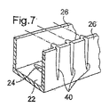
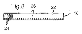
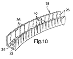
図7〜図11は、第1の実施形態を示す。 7 to 11 show the first embodiment.
この実施形態では、くぼみ40を含む圧縮による変形領域は、下側に位置する側壁26に設けられている。このくぼみ40は、互いにほぼ平行で、かつ湾曲の母線と平行な方向に延びる折り目状に形成されている。
In this embodiment, the deformation region by compression including the
図8および図9に示すように、くぼみ40を、底壁22における嵌孔24,24の間において、側壁26に設けると有利である。しかし、外側となる側壁26には、予備変形を行わない。
As shown in FIGS. 8 and 9, it is advantageous to provide a
図10に示すように、側壁26は、材料の伸張による変形を受ける。底壁22には、図6に示す変形領域38と同様の変形領域38が存在する。
As shown in FIG. 10, the
次に、図12〜図16に示す実施形態について説明する。先の実施形態と同様に、内側の側壁26には、平行な折り目状のくぼみ40が形成されている。また、外側の側壁26には、平行をなす蛇腹状凹部42が設けられ、これにより、湾曲時に外側壁が変形しやすくなっている。
Next, the embodiment shown in FIGS. 12 to 16 will be described. Similar to the previous embodiment, the
この場合、図13および図14に示すように、底壁22におけるフラットチューブを嵌合する嵌孔24の外側方において、側壁26に、蛇腹状凹部42を設けておくと有利である。
In this case, as shown in FIGS. 13 and 14, it is advantageous to provide a bellows-
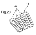
図17〜図20を参照して、フラットチューブ14の端部を受ける複数の端板44により、ヘッダ18が形成されている、本発明の別の実施形態について説明する。
With reference to FIGS. 17 to 20, another embodiment of the present invention in which the
各端板44はケーシングを形成し、その両端には、円形孔48を有する2つのボス46が連設されている。これらの端板は、互いに位置を合わせて配置され、対応する円形孔48をもって互いに連通し、コアのフラットチューブと連通するヘッダを形成している。
Each
この種の端板は、前述したフランス国特許出願第0117033号(公開第2834336号)に記載されている。 This type of end plate is described in the above-mentioned French patent application No. 0117033 (Publication No. 2834336).
端板は、ボス46同士をろう付けすることにより組み立てられている。最初に、端板44を、図18に示すように位置合わせする。次に、熱交換器全体を湾曲させる。これより、図19に示すように、端板44により形成されたヘッダは湾曲する。
The end plates are assembled by brazing the
図20は、ボスの領域に変形が生じた様子を示す。ボスは、ほぼ円錐台形であると有利であり、これにより変形が容易になる。 FIG. 20 shows a state in which deformation occurs in the boss area. The boss is advantageously substantially frustoconical, which facilitates deformation.
このようにして、ボスの変形により、蛇腹と同様に変形されたヘッダが製造される。 In this manner, a header that is deformed in the same manner as the bellows is manufactured by deformation of the boss.
図21は、フラットチューブ14を支持する端板44の具体的な実施形態を示す。図22は、図21に示す端板44とフラットチューブ14とから形成された組立体全体を湾曲させた熱交換器を示す。
FIG. 21 shows a specific embodiment of the
図17〜図20、図21および図22の実施形態では、図1に概略的に示すタイプの波形中間要素を、チューブ間に挿入することができる。 In the embodiment of FIGS. 17-20, 21 and 22, a corrugated intermediate element of the type schematically shown in FIG. 1 can be inserted between the tubes.
図23は、2つのフラットチューブ14、14の間に配置された波形中間体16により行われる変形を、誇張して示す。フラットチューブ14の拡大側50は、互いに平行であり、かつ他のチューブの拡大側と平行である。
FIG. 23 exaggerates the deformation performed by the corrugated intermediate 16 disposed between the two
最初は、フラットチューブ14および波形中間体16は、図23に実線で示す形状である。湾曲後、フラットチューブ間の角度はαとなり(図23では誇張してある)、波形中間体16も変形させられる(同様に図23では誇張してある)。湾曲後の形状を、図23に破線で示してある。
Initially, the
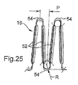
図24に示すように、波形中間体16は、最初に半径Rを有する屈曲部54により連接されたほぼ直線の部分52(必要に応じてルーバが設けられる)を備えている。一例として、この半径Rは、0.4mmとされる。
As shown in FIG. 24, the corrugated
湾曲部の外側では、波形中間体16は、伸長による変形を受ける。したがって、湾曲半径Rは減少し、例えば0.5mmから0.4mmに変化する。逆に、内側(図25)では、波形中間体16が圧縮による変形を受け、湾曲Rの半径は大となる。一例として、この内側の半径は、0.5mmから0.6mmに変化する。
Outside the curved portion, the corrugated intermediate 16 undergoes deformation due to expansion. Therefore, the radius of curvature R decreases and changes from 0.5 mm to 0.4 mm, for example. On the other hand, on the inner side (FIG. 25), the corrugated
一方、ピッチP(図24および図25)は、内側と外側の両方で同一のままである。 On the other hand, the pitch P (FIGS. 24 and 25) remains the same both inside and outside.
したがって、湾曲時の波形中間体16による変形は、屈曲部54で生じる。そのため、波形中間体16の屈曲部の曲率半径を適宜選択し、また熱交換器の湾曲領域の曲率半径を適宜選択すると、変形は波形中間体16に集中し、フラットチューブが変形することはない。またこの変形は、屈曲部に生じるため、屈曲部と熱交換器のチューブとのろう付け接合に影響を与えることはない。
Therefore, deformation by the corrugated intermediate 16 at the time of bending occurs at the
本発明による製造方法は、基本的に熱交換器のヘッダを湾曲させる作業を含んでいる。 The manufacturing method according to the present invention basically includes the operation of bending the header of the heat exchanger.
本発明により熱交換器を製造するための一実施形態では、最初に、第1の動作で、チューブコアとヘッダとを組み立てて、ほぼ平坦な構成を有する従来と同様の一般的な熱交換器を形成する。 In one embodiment for manufacturing a heat exchanger according to the present invention, first, in a first operation, a tube core and a header are assembled and a conventional general heat exchanger having a substantially flat configuration is assembled. Form.
第2の作業では、このようにして組み立てた熱交換器をろう付けして、ろう付け型熱交換器を形成する。この後に、第3の動作で、ろう付け型熱交換器を徐々に湾曲させてヘッダを湾曲させる。コアのチューブは互いにほぼ平行なままである。前述したように、波形中間体はコアのチューブの間にあるので、その変形は限定されたものとなる。 In the second operation, the heat exchanger thus assembled is brazed to form a brazed heat exchanger. Thereafter, in a third operation, the brazed heat exchanger is gradually bent to curve the header. The core tubes remain substantially parallel to each other. As described above, since the corrugated intermediate is between the core tubes, its deformation is limited.
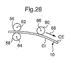
図26は、湾曲をローラにより行う方法の第1の実施形態を示す。詳細には、対向する1対のローラ56、58と、第3の移動ローラ60とを含む3個のローラにより、湾曲が行われる。これらのローラ56、58、60は、互いに平行で、かつ熱交換器のチューブの長手軸15と平行な軸62、64、66を有する。
FIG. 26 shows a first embodiment of a method for performing the bending with a roller. Specifically, the bending is performed by three rollers including a pair of
最初は平坦なろう付け型熱交換器10は、厚さに合わせた空間を間に画定する2つのローラ62、64の間を通る。熱交換器10の外側CEは、ローラ56、58から、矢印68の方向へ徐々に離れるローラ60の下を通る。
The initially flat brazed
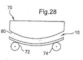
図27および図28は、プレス70と、軸76、78が互いに平行で、かつコアのチューブの長手軸15と平行な2つの反転ローラ72、74とを使用する、本発明による方法の別の実施形態を示す。
27 and 28 show another embodiment of the method according to the invention using a
プレス70は、凹状となる熱交換器10の第1の面に当接するように配置された成形面80を有する。この第1の面は、内側CIに対応する。反転ローラ72、74は、凸状となる反対側の面、すなわち外側CEに当接するようになっている。最初は平坦な熱交換器10は、交換器のチューブの長手軸15が、ローラの軸76、78とほぼ平行になるように、ローラ72、74上に配置される。
The
最初は、ローラ72、74は互いに近接しており、その後、プレスが矢印82で示す垂直方向に移動すると、矢印84で示すように、ローラ72、74は互いに離れる方向に移動する。これにより、徐々に変形が生じて、図28に示すように、完全な湾曲が生じ、ローラ72、74はできる限り互いに離れた状態に移動する。
Initially, the
プレス70の移動(矢印82)、およびローラ72、74の互いに離れる方向への移動(矢印84)は、徐々に、かつ同時に行われるのが有利である。しかし、この移動を、順次早めることも可能である。
The movement of the press 70 (arrow 82) and the movement of the
このようにして、1つまたは複数の湾曲領域を有する熱交換器を製造することができる。領域の各部分は、一定または可変の曲率半径を有することができる。 In this way, a heat exchanger having one or more curved regions can be manufactured. Each portion of the region can have a constant or variable radius of curvature.
また、1つまたは複数の湾曲領域と、1つまたは複数の非湾曲領域とを組み合わせることも可能である。湾曲領域は、対向する凹面を有して、例えば、S字型熱交換器を形成することができる。 It is also possible to combine one or more curved regions and one or more non-curved regions. The curved regions can have opposing concave surfaces to form, for example, an S-shaped heat exchanger.
以上、本発明について、2つのヘッダを有する熱交換器を参照しながら説明したが、本発明を、例えば、U字形の端部、またはヘアピンチューブが内部に開口する1つのヘッダを有する熱交換器に適用することもできる。 The present invention has been described above with reference to a heat exchanger having two headers. However, the present invention is, for example, a heat exchanger having a U-shaped end or one header having a hairpin tube open therein. It can also be applied to.
本発明を、自動車、すなわち自家用車、貨物用車、自動二輪車等の熱交換器に、好ましく適用することができる。 The present invention can be preferably applied to heat exchangers of automobiles, that is, private cars, freight cars, motorcycles and the like.
10 熱交換器
12 コア
14 フラットチューブ
15 長手軸
16 波形中間体
18、20 ヘッダ
CI、CE 湾曲領域
22 底壁
24 嵌孔
26 側壁
28 カバー
30 頂壁
32 端壁
34、36、38 変形領域
40 くぼみ
42 蛇腹状凹部
44 端板
46 ボス
48 円形孔
50 拡大側
52 直線の部分
54 屈曲部
56、58 ローラ
60 移動ローラ
62、64、66 軸
68 矢印
70 プレス
72、74 反転ローラ
76、78 軸
80 成形面
82、84 矢印
DESCRIPTION OF
Claims (18)
b)このようにして組み立てられた熱交換器(10)を、平坦にろう付けして、ろう付け型熱交換器を形成する動作と、
c)前記ろう付け型熱交換器(10)を徐々に湾曲させて、前記ヘッダ(18)(20)を湾曲させる動作とを含むことを特徴とする、請求項13に記載の方法。 a) assembling the core of the tube (14) and the header (18) (20) to form a heat exchanger having a generally flat configuration;
b) the heat exchanger (10) assembled in this way is brazed flat to form a brazed heat exchanger;
The method according to claim 13, comprising the step of: c) gradually bending the brazed heat exchanger (10) to curve the header (18) (20).
Applications Claiming Priority (2)
| Application Number | Priority Date | Filing Date | Title |
|---|---|---|---|
| FR0311303A FR2860289B1 (en) | 2003-09-26 | 2003-09-26 | HEAT EXCHANGER OF SHAPED SHAPE AND METHOD FOR MANUFACTURING THE SAME |
| PCT/FR2004/002432 WO2005031240A1 (en) | 2003-09-26 | 2004-09-27 | Curved heat exchanger and production method thereof |
Publications (2)
| Publication Number | Publication Date |
|---|---|
| JP2007506931A true JP2007506931A (en) | 2007-03-22 |
| JP2007506931A5 JP2007506931A5 (en) | 2007-11-15 |
Family
ID=34307193
Family Applications (1)
| Application Number | Title | Priority Date | Filing Date |
|---|---|---|---|
| JP2006527451A Pending JP2007506931A (en) | 2003-09-26 | 2004-09-27 | Curved heat exchanger and manufacturing method thereof |
Country Status (4)
| Country | Link |
|---|---|
| EP (1) | EP1668305A1 (en) |
| JP (1) | JP2007506931A (en) |
| FR (1) | FR2860289B1 (en) |
| WO (1) | WO2005031240A1 (en) |
Cited By (2)
| Publication number | Priority date | Publication date | Assignee | Title |
|---|---|---|---|---|
| KR20160148010A (en) * | 2014-05-06 | 2016-12-23 | 산화(항저우) 마이크로 채널 히트 익스체인저 컴퍼니 리미티드 | Bended heat exchanger |
| KR20190040974A (en) * | 2016-08-26 | 2019-04-19 | 댄포스 마이크로 채널 히트 익스체인저 (지아싱) 컴퍼니 리미티드 | Heat exchanger, heat exchanger module, and air conditioning system |
Families Citing this family (12)
| Publication number | Priority date | Publication date | Assignee | Title |
|---|---|---|---|---|
| KR101568200B1 (en) * | 2006-11-22 | 2015-11-11 | 존슨 컨트롤스 테크놀러지 컴퍼니 | Multichannel heat exchanger with dissimilar tube spacing |
| DE102006062261A1 (en) * | 2006-12-22 | 2008-06-26 | Konvekta Ag | Air conditioning system for vehicle, particularly for buses, has fluid circuit with condenser device, evaporator device and compressor unit |
| US7900689B2 (en) * | 2007-02-23 | 2011-03-08 | Delphi Technologies, Inc. | Bend relief spacer |
| EP2017563B1 (en) * | 2007-07-17 | 2009-09-23 | Delphi Technologies, Inc. | Header plate and method of manufacture thereof |
| CN101251319A (en) * | 2008-03-03 | 2008-08-27 | 孙海潮 | Cocurrent flow heat converter special for air conditioner |
| CN101603786B (en) * | 2008-06-13 | 2013-07-17 | 德尔菲技术公司 | Heat exchanger assembly with bending buffer space piece and its manufacture method |
| CN103075900A (en) * | 2013-01-17 | 2013-05-01 | 南通江华热动力机械有限公司 | Oil cooler for snowmobile |
| CN103411446B (en) * | 2013-08-28 | 2016-04-13 | 杭州三花微通道换热器有限公司 | Heat exchanger |
| KR101683948B1 (en) * | 2013-10-21 | 2016-12-07 | 현대자동차주식회사 | Heating and cooling cup holder |
| PL3133365T3 (en) * | 2014-04-16 | 2020-08-24 | Sanhua (Hangzhou) Micro Channel Heat Exchanger Co., Ltd. | Fins and bent heat exchanger with same |
| US10551131B2 (en) * | 2018-01-08 | 2020-02-04 | Hamilton Sundstrand Corporation | Method for manufacturing a curved heat exchanger using wedge shaped segments |
| US11197396B2 (en) * | 2019-09-20 | 2021-12-07 | Quanta Computer Inc. | Cooling system with curvilinear air to liquid heat exchanger |
Citations (7)
| Publication number | Priority date | Publication date | Assignee | Title |
|---|---|---|---|---|
| JPS5816185A (en) * | 1981-07-06 | 1983-01-29 | アクゾ・エヌ・ヴエ− | Device for transmitting heat through hollow fiber |
| JPS62248525A (en) * | 1986-04-18 | 1987-10-29 | Matsushita Refrig Co | Manufacture of hear exchanger |
| JPS63159666U (en) * | 1987-03-31 | 1988-10-19 | ||
| JPH01155196A (en) * | 1987-12-14 | 1989-06-19 | Nippon Denso Co Ltd | Heat exchanger and manufacture thereof |
| JPH03174971A (en) * | 1989-12-02 | 1991-07-30 | Toyo Radiator Co Ltd | Manufacture of core in heat exchanger |
| JPH0712481A (en) * | 1993-06-21 | 1995-01-17 | Toshiba Corp | Method and apparatus for manufacturing heat exchanger for air conditioning |
| JPH10206041A (en) * | 1997-01-24 | 1998-08-07 | Modine Mfg Co | Evaporator/condenser for heat pump |
Family Cites Families (2)
| Publication number | Priority date | Publication date | Assignee | Title |
|---|---|---|---|---|
| GB298541A (en) * | 1927-10-10 | 1928-12-20 | Delaunay Belleville Ets | Improvements in or relating to water tube steam boilers |
| FR2830229B1 (en) * | 2001-09-28 | 2004-01-23 | Valeo Equip Electr Moteur | FRONT PANEL OF MOTOR VEHICLE INCLUDING A BUMPER BEAM |
-
2003
- 2003-09-26 FR FR0311303A patent/FR2860289B1/en not_active Expired - Fee Related
-
2004
- 2004-09-27 EP EP04787455A patent/EP1668305A1/en not_active Withdrawn
- 2004-09-27 WO PCT/FR2004/002432 patent/WO2005031240A1/en active Application Filing
- 2004-09-27 JP JP2006527451A patent/JP2007506931A/en active Pending
Patent Citations (7)
| Publication number | Priority date | Publication date | Assignee | Title |
|---|---|---|---|---|
| JPS5816185A (en) * | 1981-07-06 | 1983-01-29 | アクゾ・エヌ・ヴエ− | Device for transmitting heat through hollow fiber |
| JPS62248525A (en) * | 1986-04-18 | 1987-10-29 | Matsushita Refrig Co | Manufacture of hear exchanger |
| JPS63159666U (en) * | 1987-03-31 | 1988-10-19 | ||
| JPH01155196A (en) * | 1987-12-14 | 1989-06-19 | Nippon Denso Co Ltd | Heat exchanger and manufacture thereof |
| JPH03174971A (en) * | 1989-12-02 | 1991-07-30 | Toyo Radiator Co Ltd | Manufacture of core in heat exchanger |
| JPH0712481A (en) * | 1993-06-21 | 1995-01-17 | Toshiba Corp | Method and apparatus for manufacturing heat exchanger for air conditioning |
| JPH10206041A (en) * | 1997-01-24 | 1998-08-07 | Modine Mfg Co | Evaporator/condenser for heat pump |
Cited By (5)
| Publication number | Priority date | Publication date | Assignee | Title |
|---|---|---|---|---|
| KR20160148010A (en) * | 2014-05-06 | 2016-12-23 | 산화(항저우) 마이크로 채널 히트 익스체인저 컴퍼니 리미티드 | Bended heat exchanger |
| KR101897385B1 (en) * | 2014-05-06 | 2018-09-10 | 산화(항저우) 마이크로 채널 히트 익스체인저 컴퍼니 리미티드 | Bended heat exchanger |
| KR20190040974A (en) * | 2016-08-26 | 2019-04-19 | 댄포스 마이크로 채널 히트 익스체인저 (지아싱) 컴퍼니 리미티드 | Heat exchanger, heat exchanger module, and air conditioning system |
| KR102329655B1 (en) * | 2016-08-26 | 2021-11-22 | 댄포스 마이크로 채널 히트 익스체인저 (지아싱) 컴퍼니 리미티드 | Heat exchangers, heat exchanger modules, and air conditioning systems |
| US11609024B2 (en) | 2016-08-26 | 2023-03-21 | Danfoss Micro Channel Heat Exchanger (Jiaxing) Co., Ltd. | Heat exchanger, heat exchanger module, and air conditioning system |
Also Published As
| Publication number | Publication date |
|---|---|
| FR2860289A1 (en) | 2005-04-01 |
| WO2005031240A1 (en) | 2005-04-07 |
| EP1668305A1 (en) | 2006-06-14 |
| FR2860289B1 (en) | 2017-10-20 |
Similar Documents
| Publication | Publication Date | Title |
|---|---|---|
| JP4724594B2 (en) | Heat exchanger | |
| US5307870A (en) | Heat exchanger | |
| US6523603B2 (en) | Double heat exchanger with condenser and radiator | |
| JP2007506931A (en) | Curved heat exchanger and manufacturing method thereof | |
| JP4724433B2 (en) | Heat exchanger | |
| EP1158260B1 (en) | Heat exchanger, method of manufacturing the heat exchanger, and method of manufacturing tube for heat exchange | |
| JP5861549B2 (en) | Tube and heat exchanger provided with the tube | |
| JP2007147172A (en) | Heat exchanger | |
| JP2006522306A (en) | Heat transfer body | |
| JP2007139416A (en) | Metal plate for producing flat tube, flat tube, and its manufacturing method | |
| EP2639539A1 (en) | Tube for heat exchanger | |
| JP4751662B2 (en) | Plate for manufacturing flat tube, method for manufacturing flat tube, and method for manufacturing heat exchanger | |
| US5890288A (en) | Method for making a heat exchanger tube | |
| US5709028A (en) | Process of manufacturing a heat exchanger | |
| US5934365A (en) | Heat exchanger | |
| US20080245518A1 (en) | Flat Tube Making Platelike Body, Flat Tube, Heat Exchanger and Process for Fabricating Heat Exchanger | |
| JP2007032952A (en) | Header tank for heat exchanger, and heat exchanger using the same | |
| JP4448354B2 (en) | Heat exchanger | |
| JP4351878B2 (en) | Heat exchanger | |
| JPH09113177A (en) | Condensor | |
| JP4852304B2 (en) | Heat exchanger | |
| JP4764647B2 (en) | Flat plate manufacturing plate, flat tube, heat exchanger, and heat exchanger manufacturing method | |
| JP2006297472A (en) | Manufacturing method of heat exchanger, and fin and tube of heat exchanger | |
| JP5250210B2 (en) | Flat tubes and heat exchangers | |
| KR100516195B1 (en) | Integrated heat exchanger for automobiles |
Legal Events
| Date | Code | Title | Description |
|---|---|---|---|
| A521 | Written amendment |
Free format text: JAPANESE INTERMEDIATE CODE: A523 Effective date: 20070926 |
|
| A621 | Written request for application examination |
Free format text: JAPANESE INTERMEDIATE CODE: A621 Effective date: 20070926 |
|
| A131 | Notification of reasons for refusal |
Free format text: JAPANESE INTERMEDIATE CODE: A131 Effective date: 20100209 |
|
| A02 | Decision of refusal |
Free format text: JAPANESE INTERMEDIATE CODE: A02 Effective date: 20100706 |