JP5250210B2 - Flat tubes and heat exchangers - Google Patents
Flat tubes and heat exchangers Download PDFInfo
- Publication number
- JP5250210B2 JP5250210B2 JP2007125388A JP2007125388A JP5250210B2 JP 5250210 B2 JP5250210 B2 JP 5250210B2 JP 2007125388 A JP2007125388 A JP 2007125388A JP 2007125388 A JP2007125388 A JP 2007125388A JP 5250210 B2 JP5250210 B2 JP 5250210B2
- Authority
- JP
- Japan
- Prior art keywords
- side wall
- wall forming
- flat
- forming portion
- wall
- Prior art date
- Legal status (The legal status is an assumption and is not a legal conclusion. Google has not performed a legal analysis and makes no representation as to the accuracy of the status listed.)
- Expired - Fee Related
Links
Images


Description
この発明は、熱交換器の熱交換管、たとえばカーエアコンのコンデンサやエバポレータの冷媒流通管、自動車用オイルクーラのオイル流通管、自動車用ラジエータのエンジン冷却水流通管、ヒータコアのエンジン冷却水流通管などとして使用される扁平管および扁平管を用いた熱交換器に関する。 The present invention relates to a heat exchange pipe for a heat exchanger, such as a condenser for an air conditioner or a refrigerant circulation pipe for an evaporator, an oil circulation pipe for an automobile oil cooler, an engine cooling water circulation pipe for an automobile radiator, and an engine cooling water circulation pipe for a heater core. The present invention relates to a flat tube and a heat exchanger using the flat tube.
この明細書において、「アルミニウム」という用語には、純アルミニウムの他にアルミニウム合金を含むものとする。 In this specification, the term “aluminum” includes aluminum alloys in addition to pure aluminum.
たとえば車両のカーエアコンのコンデンサに適用される熱交換器(70)としては、図14に示すように、上下方向にのびかつ左右方向に間隔をおいて配置された1対のアルミニウム製ヘッダ(71)(72)と、両ヘッダ(71)(72)間において幅方向を通風方向に向けるとともに上下方向に間隔をおいて配置され、かつ両端部が両ヘッダ(71)(72)に接続された複数のアルミニウム製熱交換管(73)と、隣り合う熱交換管(73)どうしの間、および上下両端の熱交換管(73)の外側に配置されて熱交換管(73)にろう付されたアルミニウム製コルゲートフィン(74)と、上下両端のコルゲートフィン(74)の外側に配置されてコルゲートフィン(74)にろう付されたサイドプレート(75)とよりなり、左側ヘッダ(71)が、高さ方向の中央部よりも上方において仕切部材(76)により上下2つのヘッダ部(71a)(71b)に仕切られ、右側ヘッダ(72)が、高さ方向の中央部よりも下方において仕切部材(76)により上下2つのヘッダ部(72a)(72b)に仕切られ、左側ヘッダ(71)の上ヘッダ部(71a)に流体入口(図示略)が形成され、流体入口に通じる流体流入路(77a)を有する入口部材(77)が上ヘッダ部(71a)にろう付され、右側ヘッダ(72)の下ヘッダ部(72b)に流体出口(図示略)が形成され、流体出口に通じる流体流出路(78a)を有する出口部材(78)が下ヘッダ部(72b)にろう付されているものが広く用いられている(特許文献1参照)。 For example, as shown in FIG. 14, as a heat exchanger (70) applied to a condenser of a car air conditioner of a vehicle, a pair of aluminum headers (71) extending in the vertical direction and spaced apart in the horizontal direction are arranged. ) (72) and both headers (71) (72) are oriented in the width direction in the ventilation direction and spaced apart in the vertical direction, and both ends are connected to both headers (71) (72) It is placed between the heat exchange tubes (73) made of aluminum and the adjacent heat exchange tubes (73) and outside the heat exchange tubes (73) at both upper and lower ends and brazed to the heat exchange tubes (73). The aluminum corrugated fin (74) and the side plate (75) brazed to the corrugated fin (74) arranged outside the corrugated fin (74) at both the upper and lower ends, the left header (71), Upper and lower two header parts (7) by the partition member (76) above the central part in the height direction 1a) (71b), the right header (72) is divided into two upper and lower header parts (72a) (72b) by the partition member (76) below the center in the height direction, and the left header ( 71) A fluid inlet (not shown) is formed in the upper header portion (71a), and an inlet member (77) having a fluid inflow passage (77a) communicating with the fluid inlet is brazed to the upper header portion (71a) A fluid outlet (not shown) is formed in the lower header portion (72b) of the header (72), and an outlet member (78) having a fluid outflow passage (78a) communicating with the fluid outlet is brazed to the lower header portion (72b). Are widely used (see Patent Document 1).
上述した熱交換器(70)の左右のヘッダ(71)(72)は、少なくとも外面にろう材層を有するアルミニウム製パイプ、たとえば両面にろう材層を有するアルミニウムブレージングシートからなる素板が筒状に成形されるとともに両側縁部が部分的に重ね合わされて相互にろう付されたろう付パイプからなるヘッダ本体(80)と、ヘッダ本体(80)の両端にろう付されてその両端開口を閉鎖するアルミニウム製閉鎖部材(81)とからなる。 The left and right headers (71), (72) of the heat exchanger (70) described above are cylindrical pipes made of aluminum brazing sheets having brazing material layers on at least the outer surfaces, for example, aluminum brazing sheets having brazing material layers on both sides. The header body (80) is made of a brazed pipe that is molded into a piece and brazed to each other with the side edges partially overlapped, and the both ends of the header body (80) are brazed to close the openings at both ends. And an aluminum closing member (81).
上記熱交換器(70)の熱交換管(73)は、熱交換効率が優れていることはもちろんのこと、その内部に高圧ガス冷媒が導入されるため耐圧性が要求される。しかも、コンデンサのコンパクト化を図るため扁平管の管壁が薄肉でかつ管高さが低いことが要求される。 The heat exchanger pipe (73) of the heat exchanger (70) is required not only to have excellent heat exchange efficiency but also to have pressure resistance because high-pressure gas refrigerant is introduced into the heat exchanger pipe (73). Moreover, in order to reduce the size of the capacitor, it is required that the tube wall of the flat tube is thin and the tube height is low.
上述したコンデンサに用いられる熱交換効率に優れた扁平管として、特許文献1に記載されたものが用いられていた。特許文献1に記載された扁平管は、互いに対向する1対の平坦壁と、両平坦壁の両側縁どうしにまたがって設けられた2つの側壁と、両側壁間において両平坦壁にまたがるとともに長さ方向に伸びかつ相互に所定間隔をおいて設けられた複数の補強壁とを備えているとともに、内部に複数の並列状流体通路を有しており、第1の側壁が両平坦壁と一体に形成され、第2の側壁が、各平坦壁の側縁に一体成形されて他の平坦壁側に突出し、かつ先端どうしが当接させられてろう付された側壁形成部により形成されている。 What was described in patent document 1 was used as a flat tube excellent in the heat exchange efficiency used for the capacitor | condenser mentioned above. The flat tube described in Patent Document 1 spans a pair of flat walls facing each other, two side walls provided across both side edges of both flat walls, and spans both flat walls between both side walls. A plurality of reinforcing walls extending in the vertical direction and spaced apart from each other, and having a plurality of parallel fluid passages therein, the first side wall being integrated with both flat walls The second side wall is formed by a side wall forming portion that is integrally formed on the side edge of each flat wall and protrudes to the other flat wall side, and is brazed with the tips being brought into contact with each other. .
このような扁平管は、全体が1枚の金属板よりなり、両平坦壁を形成する同幅の2つの平坦壁形成部、平坦壁形成部どうしを連結しかつ第1側壁を形成する連結部、両平坦壁形成部における連結部とは反対側の側縁にそれぞれ隆起状に一体成形されかつ第2側壁を形成する側壁形成部、および両平坦壁形成部にそれぞれ隆起状に一体成形された補強壁形成部を有する扁平管製造用板状体を、連結部においてヘアピン状に曲げ、両側壁形成部の先端どうしを突き合わせて相互にろう付するとともに、一方の平坦壁形成部に形成された補強壁形成部の先端と他方の平坦壁形成部に形成された補強壁形成部の先端とを突き合わせて相互にろう付することにより製造されている。そして、2つの側壁形成部どうしを突き合わせて相互にろう付することにより形成された第2側壁の肉厚は、連結部からなる第1側壁の肉厚よりも薄くなっている。 Such a flat tube is made of a single metal plate as a whole, and has two flat wall forming portions of the same width that form both flat walls, a connecting portion that connects the flat wall forming portions and forms the first side wall. In the two flat wall forming portions, the side edges opposite to the connecting portions are integrally formed in a raised shape, and the side wall forming portion forming the second side wall and the two flat wall forming portions are integrally formed in the raised shape. A flat tube manufacturing plate-like body having a reinforcing wall forming portion is bent into a hairpin shape at a connecting portion, and the ends of both side wall forming portions are brought into contact with each other and brazed to each other, and formed on one flat wall forming portion. The tip of the reinforcing wall forming portion and the tip of the reinforcing wall forming portion formed on the other flat wall forming portion are brought into contact with each other and brazed to each other. And the thickness of the 2nd side wall formed by making two side wall formation parts face each other and brazing is thinner than the thickness of the 1st side wall which consists of a connection part.
しかしながら、特許文献1記載の扁平管を上述したようなコンデンサに使用した場合、飛来した石等が2つの側壁形成部からなる第2側壁に当たると、その衝撃により第2側壁が破損するおそれがある。 However, when the flat tube described in Patent Document 1 is used for the capacitor as described above, when the flying stone hits the second side wall formed of the two side wall forming portions, the second side wall may be damaged by the impact. .
そこで、このような問題を解決するために、本出願人は、先に、互いに対向する1対の平坦壁と、両平坦壁の両側縁どうしにまたがって設けられた2つの側壁とを備えており、第1の側壁が両平坦壁と一体に形成され、第2の側壁が両平坦壁の側縁に一体成形された複数の側壁形成部を組み合わせることにより形成されており、第2側壁が、第1平坦壁の外側縁に形成されて第2平坦壁側に突出し、かつ先端が第2平坦壁に当接した第1側壁形成部と、第1平坦壁における第1側壁形成部の内側部分に形成されて第2平坦壁側に突出し、かつ先端が第2側壁の高さの中間部に位置する第2側壁形成部と、第2平坦壁の外側縁に形成されて第1平坦壁側に突出し、かつ先端が第2側壁形成部の先端面に当接した第2側壁形成部とよりなり、第1側壁形成部の先端と第2平坦壁、第1側壁と第2および第3側壁形成部、および第2側壁形成部と第3側壁形成部とがろう付されている扁平管を提案した(特許文献2参照)。 Therefore, in order to solve such a problem, the present applicant previously provided a pair of flat walls facing each other and two side walls provided across both side edges of both flat walls. The first side wall is formed integrally with the two flat walls, the second side wall is formed by combining a plurality of side wall forming portions formed integrally with the side edges of the two flat walls, and the second side wall is A first side wall forming part formed on an outer edge of the first flat wall and projecting toward the second flat wall side and having a tip abutting against the second flat wall; and an inner side of the first side wall forming part in the first flat wall A first side wall formed on the outer edge of the second flat wall, and a second side wall forming part which is formed in a portion and protrudes toward the second flat wall side and whose tip is located at an intermediate portion of the height of the second side wall. And a second side wall forming portion that protrudes to the side and a front end of which contacts the front end surface of the second side wall forming portion. A flat tube is proposed in which the tip of the wall forming part and the second flat wall, the first side wall and the second and third side wall forming parts, and the second side wall forming part and the third side wall forming part are brazed (patent) Reference 2).
特許文献2記載の扁平管は、全体が1枚の金属板よりなり、2つの平坦壁形成部と、両平坦壁形成部を一体に連結しかつ第1側壁を形成する連結部と、両平坦壁形成部における連結部とは反対側の側縁に、それぞれ平坦壁形成部から隆起するように設けられた第2および第3側壁形成部と、第1平坦壁形成部における連結部とは反対側の側縁を延長することにより設けられた第1側壁形成部用延長部とを備えている扁平管製造用板状体を、連結部の両側においてヘアピン状に折り曲げて第2および第3側壁形成部の先端部どうしを突き合わせること、第1側壁形成部用延長部を折り曲げて第1側壁形成部をつくるとともに、第1側壁形成部によって第2および第3側壁形成部の外面を覆ってかしめることにより折り曲げ体を作ること、ならびに折り曲げ体の第1側壁形成部の内側面の先端部と第2平坦壁形成部の第2側壁側(連結部とは反対側)の端面、第1側壁形成部と第2および第3側壁形成部、および第2側壁形成部と第3側壁形成部とを同時にろう付することにより製造される。したがって、第1側壁形成部と第2平坦壁形成部の第2側壁側の端面とのろう付部は、扁平管の一方の面に存在することになる。
The flat tube described in
ところで、特許文献2の扁平管は、図14に示す熱交換器の製造と同時に製造される。すなわち、少なくとも外面にろう材層を有し、かつ複数の管挿通穴を有するパイプ状のアルミニウム製ヘッダ本体素材を互いに間隔をおいて配置すること、各ヘッダ本体素材の両端に閉鎖部材を配置すること、各ヘッダ本体素材に仕切部材を配置すること、特許文献2記載の扁平管を製造する際の上述した折り曲げ体の両端部を両ヘッダ本体素材の管挿通穴内に嵌め入れること、隣り合う折り曲げ体間および両端の折り曲げ体の外側にコルゲートフィンを配置すること、両端のコルゲートフィンの外側にサイドプレートを配置すること、一方のヘッダ本体素材に入口部材を、他方のヘッダ本体素材に出口部材を配置すること、ならびに所定温度に加熱して折り曲げ体から上述のようにして扁平管を製造すると同時に、他の部品を一括してろう付することにより、熱交換器が製造される。
By the way, the flat tube of
しかしながら、特許文献2を製造する際の上述した折り曲げ体においては、第1側壁形成部と第2平坦壁の第2側壁側の端面との継ぎ目部分が、コルゲートフィンがろう付される面に存在することになる。したがって、熱交換器を製造する際に、ヘッダ本体素材から溶け出した溶融ろう材が、毛細管現象により、上記継ぎ目部分に沿って流れるとともに、折り曲げ体とコルゲートフィンとの接触部に沿って流れる。その結果、ヘッダ本体素材の外面を覆うろう材量を多くしておかなければならず、材料コストが高くなり、ひいては熱交換器の製造コストが高くなるという問題がある。
この発明の目的は、上記問題を解決し、熱交換器を製造する際の製造コストを低減しうる扁平管および熱交換器を提供することにある。 An object of the present invention is to provide a flat tube and a heat exchanger that can solve the above-described problems and can reduce the manufacturing cost when manufacturing the heat exchanger.
本発明は、上記目的を達成するために以下の態様からなる。 In order to achieve the above object, the present invention comprises the following aspects.
1)互いに対向する1対の平坦壁と、両平坦壁の両側縁どうしにまたがって設けられた2つの側壁とを備えており、第1の側壁が両平坦壁と一体に形成され、第2の側壁が両平坦壁の側縁部に一体成形された複数の側壁形成部を組み合わせることにより形成され、2つの平坦壁形成部と、両平坦壁形成部を一体に連結しかつ第1側壁を形成する連結部と、両平坦壁形成部における連結部とは反対側の側縁部に設けられた複数の側壁形成部とを備えている扁平管製造用板状体を、連結部においてヘアピン状に折り曲げ、さらにすべての側壁形成部を組み合わせてかしめることにより折り曲げ体を得た後、複数の側壁形成部をろう付することにより第2側壁がつくられており、横断面形状におけるろう付部の外側端部が、第2側壁の外面のみに全長にわたって露出している扁平管において、
第2側壁が、第1平坦壁の外側縁に形成されて第2平坦壁側に突出し、かつ先端が第2平坦壁に当接した第1側壁形成部と、第1平坦壁における第1側壁形成部の内側部分に間隔をおいて形成されて第2平坦壁側に突出し、かつ先端が第2側壁の高さの中間部に位置する厚肉部分、および厚肉部分の先端面の肉厚方向外側に一体に形成されて第2平坦壁側に突出するとともに先端が第2平坦壁に当接した薄肉部分よりなる第2側壁形成部と、第2平坦壁に形成されて第1平坦壁側に突出し、かつ第1側壁形成部と第2側壁形成部との間に嵌め入れられるとともに、先端が第1平坦壁に当接した第3側壁形成部と、第2平坦壁における第3側壁形成部の内側部分に間隔をおいて形成されて第1平坦壁側に突出し、かつ先端が第2側壁形成部の厚肉部分の先端面における肉厚方向内側に当接した第4側壁形成部とよりなり、両平坦壁の第2側壁側縁部の端面と第1側壁形成部の外面とにより第2側壁の外面が形成され、横断面形状において、第2平坦壁と第1側壁形成部の先端とのろう付部の外側端部が、第2側壁の外面に露出している扁平管。
1) It is provided with a pair of flat walls facing each other and two side walls provided across both side edges of both flat walls, the first side wall being formed integrally with both flat walls, The side walls of the two flat walls are formed by combining a plurality of side wall forming portions formed integrally with the side edges of the two flat walls, and the two flat wall forming portions and the two flat wall forming portions are integrally connected and the first side wall is formed. A flat tube manufacturing plate-like body provided with a connecting portion to be formed and a plurality of side wall forming portions provided on a side edge portion opposite to the connecting portion in both flat wall forming portions, and a hairpin shape at the connecting portion The second side wall is formed by brazing a plurality of side wall forming portions after the bent body is obtained by bending and bending all the side wall forming portions in combination. The outer end of the entire length only on the outer surface of the second side wall In flat tubes are exposed over,
A second side wall formed on an outer edge of the first flat wall, protruding toward the second flat wall, and having a tip abutting against the second flat wall; and a first side wall of the first flat wall A thick part formed at an interval in the inner part of the forming part and projecting to the second flat wall side and having a tip located at the middle part of the height of the second side wall, and a thickness of the tip surface of the thick part A second side wall forming portion formed of a thin wall portion integrally formed on the outer side in the direction and protruding toward the second flat wall side and having a tip abutting against the second flat wall; and a first flat wall formed on the second flat wall. And a third side wall forming portion that is fitted between the first side wall forming portion and the second side wall forming portion and whose tip is in contact with the first flat wall, and a third side wall in the second flat wall the first projecting flat wall side to the inner portion of the forming portion are formed at intervals and tip of the second side wall forming portion thickness, The fourth side wall forming portion is in contact with the inner side in the thickness direction on the front end surface of the portion, and the outer surface of the second side wall is formed by the end surface of the second side wall side edge of both flat walls and the outer surface of the first side wall forming portion. A flat tube which is formed and has an outer end portion of the brazed portion between the second flat wall and the tip of the first side wall forming portion exposed on the outer surface of the second side wall in a cross-sectional shape.
2)第2側壁の肉厚が、平坦壁の肉厚の1.5〜5倍となっている上記1)記載の扁平管。 2) The flat tube as described in 1) above, wherein the thickness of the second side wall is 1.5 to 5 times the thickness of the flat wall.
3)横断面形状において、第2側壁を形成する全側壁形成部のろう付長さが、第2側壁の肉厚の1.3〜7倍となっている上記1)または2)記載の扁平管。 3) The flat shape as described in 1) or 2) above, wherein in the cross-sectional shape, the brazing length of the entire side wall forming part forming the second side wall is 1.3 to 7 times the wall thickness of the second side wall. tube.
4)互いに間隔をおいて平行に配置された1対のヘッダ間に、上記1)〜3)のうちのいずれかに記載された複数の扁平管が相互に間隔をおいて並列状に位置され、すべての扁平管の両端がそれぞれ両ヘッダに接続され、隣り合う扁平管間の通風間隙にフィンが配置されるとともに、フィンが扁平管にろう付されている熱交換器。 4) between a pair arranged in parallel at intervals in another header, the 1) located in parallel form a plurality of flat tubes that are described at intervals from each other in any one of 1-3) A heat exchanger in which both ends of all flat tubes are connected to both headers, fins are arranged in the ventilation gap between adjacent flat tubes, and the fins are brazed to the flat tubes.
上記1)の扁平管によれば、第2側壁の外面のみに、全長にわたるろう付部が存在しているので、2つの平坦壁形成部と、両平坦壁形成部を一体に連結しかつ第1側壁を形成する連結部と、両平坦壁形成部における連結部とは反対側の側縁部に設けられた複数の側壁形成部とを備えている扁平管製造用板状体を、連結部においてヘアピン状に折り曲げ、さらにすべての側壁形成部を組み合わせてかしめることにより折り曲げ体を得た際には、第2側壁を形成する部分の外面のみに継ぎ目部分が存在することになる。したがって、当該扁平管を、たとえば図14に示す熱交換器の製造と同時に製造する場合、すなわち少なくとも外面にろう材層を有し、かつ複数の管挿通穴を有するアルミニウム製ヘッダ本体素材を互いに間隔をおいて配置すること、各ヘッダ本体素材の両端に閉鎖部材を配置すること、各ヘッダ本体素材に仕切部材を配置すること、上記1)の扁平管を製造する際の上述した折り曲げ体の両端部を両ヘッダ本体素材の管挿通穴内に嵌め入れること、隣り合う折り曲げ体間および両端の折り曲げ体の外側にコルゲートフィンを配置すること、両端のコルゲートフィンの外側にサイドプレートを配置すること、一方のヘッダ本体素材に入口部材を、他方のヘッダ本体素材に出口部材を配置すること、ならびに所定温度に加熱して折り曲げ体から上記1)の扁平管を製造すると同時に、他の部品を一括してろう付することによりなる方法により熱交換器を製造する場合にも、ヘッダ本体素材から溶け出した溶融ろう材が、毛細管現象により、上記継ぎ目部分に沿って流れることが防止され、その結果折り曲げ体とコルゲートフィンとの接触部に沿って流れることも防止される。したがって、ヘッダ本体素材の外面を覆うろう材量を少なくすることが可能になり、材料コストが安くなって熱交換器の製造コストを低減することができる。 According to the flat tube of the above 1), since the brazing portion extending over the entire length exists only on the outer surface of the second side wall, the two flat wall forming portions and the two flat wall forming portions are integrally connected and A flat tube manufacturing plate-like body comprising a connecting portion forming one side wall and a plurality of side wall forming portions provided on a side edge portion opposite to the connecting portion in both flat wall forming portions, When a bent body is obtained by bending into a hairpin shape and further caulking all the side wall forming portions in combination, a seam portion exists only on the outer surface of the portion forming the second side wall. Therefore, when the flat tube is manufactured at the same time as the manufacture of the heat exchanger shown in FIG. 14, for example, the aluminum header body material having a brazing filler metal layer on at least the outer surface and a plurality of tube insertion holes is spaced from each other. , Disposing a closing member on each end of each header body material, disposing a partition member on each header body material, both ends of the above-described bent body when manufacturing the flat tube of 1) above Part is inserted into the pipe insertion holes of both header body materials, corrugated fins are arranged between adjacent bent bodies and outside the bent bodies at both ends, side plates are arranged outside the corrugated fins at both ends, An inlet member is placed on the header body material of the other, and an outlet member is placed on the other header body material. When the heat exchanger is manufactured by the method of brazing together other parts at the same time as the flat tube of 1) is manufactured, the molten brazing material that has melted from the header body material is caused by capillary action. The flow along the seam portion is prevented, and as a result, the flow along the contact portion between the bent body and the corrugated fin is also prevented. Accordingly, the amount of brazing material covering the outer surface of the header body material can be reduced, the material cost can be reduced, and the manufacturing cost of the heat exchanger can be reduced.
上記2)の扁平管によれば、第2側壁の肉厚が、平坦壁の肉厚の1.5〜5倍となっているので、たとえばコンデンサなどの熱交換器に使用した場合にも、異物の衝突時による第2側壁の破損が防止され、冷媒などの洩れが防止される。 According to the flat tube of 2) above, since the thickness of the second side wall is 1.5 to 5 times the thickness of the flat wall, even when used in a heat exchanger such as a condenser, The second side wall is prevented from being damaged due to the collision of the foreign matter, and leakage of the refrigerant is prevented.
上記3)の扁平管によれば、横断面形状において、第2側壁を形成する全側壁形成部のろう付長さが、第2側壁の肉厚の1.3〜7倍となっているので、ろう付強度が向上するとともに、ろう付部の腐食による耐食性の低下を防止することができる。 According to the flat tube of the above 3), in the cross-sectional shape, the brazing length of the entire side wall forming part forming the second side wall is 1.3 to 7 times the wall thickness of the second side wall. The brazing strength can be improved and the corrosion resistance can be prevented from lowering due to the corrosion of the brazed portion.
上記4)の熱交換器を製造する際には、上記1)と同様な効果を奏する。 When producing the heat exchanger of 4), the same effects as in 1) are obtained.
以下、この発明の実施形態を、図面を参照して説明する。なお、以下の説明において、図1〜図3、図6、図8、図10、図12の上下、左右をそれぞれ上下、左右というものとする。 Embodiments of the present invention will be described below with reference to the drawings. In the following description, the upper and lower sides and the left and right sides of FIGS.
なお、全図面を通じて同一部分および同一物には同一符号を付して重複する説明を省略する。 In addition, the same code | symbol is attached | subjected to the same part and the same thing through all drawings, and the overlapping description is abbreviate | omitted.
実施形態1
この実施形態は図1〜図6に示すものである。
Embodiment 1
This embodiment is shown in FIGS.
図1および図2は実施形態1の扁平管を示し、図3は扁平管を製造するのに用いられる扁平管製造用板状体を示し、図4〜図6は扁平管を製造する工程の一部を示す。 1 and 2 show the flat tube of Embodiment 1, FIG. 3 shows a flat tube manufacturing plate used for manufacturing the flat tube, and FIGS. 4 to 6 show the steps of manufacturing the flat tube. Some are shown.
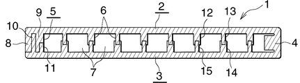
図1および図2において、扁平管(1)はアルミニウム製であり、互いに対向しかつ同一肉厚である平らな上下壁(2)(3)(1対の平坦壁)と、上下壁(2)(3)の右側縁どうしにまたがりかつ上下壁(2)(3)と一体に形成された右側壁(4)(第1側壁)と、上下壁(2)(3)の左側縁どうしにまたがりかつ上下壁(2)(3)の左側縁部に一体成形された複数の側壁形成部を組み合わせることにより形成された左側壁(5)(第2側壁)と、両側壁間(4)(5)において上下壁(2)(3)にまたがるとともに相互に所定間隔をおいて設けられ、かつ長さ方向に伸びる複数の補強壁(6)とよりなり、内部に並列状の複数の流体通路(7)を有するものである。なお、図示は省略したが、全ての補強壁(6)には、隣接する流体通路(7)どうしを通じさせる複数の連通穴が、全体として平面から見て千鳥配置状となるようにあけられている。 In FIG. 1 and FIG. 2, the flat tube (1) is made of aluminum, and has flat upper and lower walls (2) and (3) (a pair of flat walls) facing each other and having the same thickness, and upper and lower walls (2 ) (3) The right side wall (4) (first side wall) and the left side edge of the top and bottom walls (2) (3) The left side wall (5) (second side wall) formed by combining a plurality of side wall forming parts integrally formed on the left side edge of the upper and lower walls (2) and (3), and between the side walls (4) ( 5) a plurality of reinforcing walls (6) extending over the upper and lower walls (2) (3) and spaced apart from each other and extending in the length direction, and a plurality of fluid passages arranged in parallel inside (7) Although not shown in the figure, all the reinforcing walls (6) are provided with a plurality of communication holes through which the adjacent fluid passages (7) pass so as to form a staggered arrangement as viewed from above. Yes.
左側壁(5)は、上壁(2)(第1平坦壁)に一体に形成された第1側壁形成部(8)および第2側壁形成部(9)と、下壁(3)(第2平坦壁)に一体に形成された第3側壁形成部(10)および第4側壁形成部(11)とを組み合わせてろう付することにより形成されている。 The left side wall (5) includes a first side wall forming part (8) and a second side wall forming part (9) formed integrally with the upper wall (2) (first flat wall), and a lower wall (3) (first The second side wall forming portion (10) and the fourth side wall forming portion (11) integrally formed on the (2 flat walls) are brazed in combination.
第1側壁形成部(8)は、上壁(2)(第1平坦壁)の左側縁(外側縁)に一体に形成されて下壁(3)(第2平坦壁)側に突出し、かつ先端が下壁(3)上面に当接して下壁(3)にろう付されている。第2側壁形成部(9)は、上壁(2)における第1側壁形成部(8)の右側部分(内側部分)に間隔をおいて一体に形成されて下壁(3)側に突出し、かつ先端が左側壁(5)の高さの中間部に位置する厚肉部分(9a)、および厚肉部分(9a)の先端面の左側(肉厚方向外側)に一体に形成されて下壁(3)側に突出し、かつ先端が下壁(3)上面に当接して下壁(3)にろう付された薄肉部分(9b)よりなる。第3側壁形成部(10)は、下壁(3)に一体に形成されて上壁(2)側に突出し、かつ第1側壁形成部(8)と第2側壁形成部(9)との間に嵌め入れられるとともに、先端が上壁(2)に当接した状態で、第1および第2側壁形成部(8)(9)と上壁(2)にろう付されている。第4側壁形成部(11)は、下壁(3)における第3側壁形成部(10)の右側部分に間隔をおいて一体に形成されて上壁(2)側に突出し、かつ先端が第2側壁形成部(9)の厚肉部分(9a)の先端面の右側(肉厚方向内側)に当接した状態で、第2側壁形成部(9)にろう付されている。そして、上下壁(2)(3)の左端面(第2側壁(4)側縁部の端面)と第1側壁形成部(8)の外面とにより左側壁(5)の外面が形成され、下壁(3)と第1側壁形成部(8)の先端とのろう付部が、左側壁(5)の外面に存在している。 The first side wall forming portion (8) is integrally formed on the left edge (outer edge) of the upper wall (2) (first flat wall), protrudes toward the lower wall (3) (second flat wall), and The tip is in contact with the upper surface of the lower wall (3) and brazed to the lower wall (3). The second side wall forming part (9) is integrally formed with a space on the right side part (inner part) of the first side wall forming part (8) in the upper wall (2) and protrudes toward the lower wall (3). And the thick wall part (9a) located at the middle of the height of the left side wall (5), and the lower wall integrally formed on the left side (outside in the thickness direction) of the front end surface of the thick part (9a) It consists of a thin-walled portion (9b) that protrudes to the (3) side and whose tip is in contact with the upper surface of the lower wall (3) and brazed to the lower wall (3). The third side wall forming portion (10) is formed integrally with the lower wall (3) and protrudes toward the upper wall (2), and is formed between the first side wall forming portion (8) and the second side wall forming portion (9). The first and second side wall forming portions (8), (9) and the upper wall (2) are brazed with the tip inserted between them and in contact with the upper wall (2). The fourth side wall forming portion (11) is formed integrally with the right side portion of the third side wall forming portion (10) in the lower wall (3) at an interval, protrudes toward the upper wall (2), and the tip is the first. The second side wall forming portion (9) is brazed to the second side wall forming portion (9) while being in contact with the right side (thickness direction inner side) of the front end surface of the thick portion (9a) of the thick side wall forming portion (9). And the outer surface of the left side wall (5) is formed by the left end surface (end surface of the second side wall (4) side edge) of the upper and lower walls (2) and (3) and the outer surface of the first side wall forming portion (8), A brazed portion between the lower wall (3) and the tip of the first side wall forming portion (8) exists on the outer surface of the left side wall (5).
補強壁(6)は、上壁(2)より下方隆起状に一体成形された補強壁用凸条(12)(13)と、下壁(3)より上方隆起状に一体成形された補強壁用凸条(14)(15)とが、先端どうしが相互に突き合わされてろう付されることにより形成されている。上壁(2)および下壁(3)には、それぞれ肉厚の異なる2種類の補強壁用凸条(12)(13)および(14)(15)が左右方向に交互に形成されており、上壁(2)における肉厚の厚い補強壁用凸条(12)と下壁(3)における肉厚の薄い補強壁用凸条(15)とがろう付され、上壁(2)における肉厚の薄い補強壁用凸条(13)と下壁(3)における肉厚の厚い補強壁用凸条(14)とがろう付されている。以下、上下両壁(2)(3)の肉厚の厚い補強壁用凸条(12)(14)をそれぞれ第1補強壁用凸条といい、同じく薄い補強壁用凸条(13)(15)をそれぞれ第2補強壁用凸条というものとする。上下壁(2)(3)の第1補強壁用凸条(12)(14)の先端面には、それぞれその長さ方向に伸びかつ他方の壁(3)(2)の第2補強壁用凸条(15)(13)の先端部が嵌る凹溝(16)(17)が全長にわたって形成されている。そして、上壁(2)の第1補強壁用凸条(12)の凹溝(16)内に下壁(3)の第2補強壁用凸条(15)の先端部が、下壁(3)の第1補強壁用凸条(14)の凹溝(17)内に上壁(2)の第2補強壁用凸条(13)の先端部がそれぞれ圧入された状態で、両補強壁用凸条(12)(15)および(13)(14)がろう付されている。 The reinforcing wall (6) is a reinforcing wall projection (12) (13) integrally formed in a raised shape below the upper wall (2) and a reinforcing wall integrally formed in a raised shape above the lower wall (3). The projecting ridges (14) and (15) are formed by brazing the tips with each other being abutted against each other. On the upper wall (2) and lower wall (3), two types of reinforcing wall ridges (12) (13) and (14) (15) with different thicknesses are formed alternately in the left-right direction. The thick reinforcing wall ridges (12) on the upper wall (2) and the thin reinforcing wall ridges (15) on the lower wall (3) are brazed, and the upper wall (2) The thin reinforcing wall ridge (13) and the thick reinforcing wall ridge (14) on the lower wall (3) are brazed. Hereinafter, the thick reinforcing wall projections (12) and (14) on both the upper and lower walls (2) and (3) are referred to as first reinforcement wall projections, respectively, and the thin reinforcement wall projections (13) ( 15) shall be called the second reinforcing wall projections. The first reinforcing wall projections (12) and (14) of the upper and lower walls (2) and (3) are respectively extended in the length direction thereof and the second reinforcing wall of the other wall (3) and (2). Concave grooves (16) and (17) into which the tips of the projecting ridges (15) and (13) fit are formed over the entire length. And the front-end | tip part of the 2nd reinforcement wall protruding item | line (15) of the lower wall (3) is in the recessed wall (16) of the protruding item | line (12) for the 1st reinforcement wall of the upper wall (2), and the lower wall ( In the state where the tip of the second reinforcing wall projection (13) of the upper wall (2) is press-fitted into the concave groove (17) of the first reinforcing wall projection (14) of 3), both reinforcements Wall ridges (12) (15) and (13) (14) are brazed.
扁平管(1)は、図3に示す扁平管製造用板状体(20)を用いて製造される。 The flat tube (1) is manufactured using the flat tube manufacturing plate (20) shown in FIG.
図3において、扁平管製造用板状体(20)は、全体が両面にろう材層を有するアルミニウムブレージングシートからなる圧延素板を圧延することにより形成されたものであり、上下壁(2)(3)を形成する相互に同幅および同肉厚の平らな上壁形成部(21)(平坦壁形成部)および下壁形成部(22)(平坦壁形成部)と、上下壁形成部(21)(22)どうしを一体に連結するとともに右側壁(4)を形成する連結部(23)と、上壁形成部(21)の右側縁に右方に真っ直ぐに突出するように一体に形成された第1側壁形成部用延長部(24)と、上壁形成部(21)の右側縁部上面に上方突出状に一体に形成され、かつ厚肉部分(9a)および薄肉部分(9b)よりなる第2側壁形成部(9)と、下壁形成部(22)の左側縁部上面に左右方向に間隔をおいて上方突出状に一体に形成された第3側壁形成部(10)および第4側壁形成部(11)と、上壁形成部(21)および下壁形成部(22)にそれぞれ左右方向に所定間隔をおいて上方隆起状に一体成形された複数の第1および第2補強壁用凸条(12)(13)(14)(15)とを備えており、上壁形成部(21)の第1補強壁用凸条(12)と下壁形成部(22)の第2補強壁用凸条(15)、および下壁形成部(22)の第1補強壁用凸条(14)と上壁形成部(21)の第2補強壁用凸条(13)とが、それぞれ連結部(23)の左右方向の中心線に対して左右対称となる位置にある。扁平管製造用板状体(20)を形成するためのアルミニウムブレージングシートは、たとえばAl−Mn系合金製の芯材の両面にアルミニウムろう材層が形成されたものであり、上下両アルミニウムろう材層のクラッド率は同一である。 In FIG. 3, the flat tube manufacturing plate (20) is formed by rolling a rolling base plate made of an aluminum brazing sheet having a brazing filler metal layer on both sides, and includes upper and lower walls (2). Flat upper wall forming part (21) (flat wall forming part) and lower wall forming part (22) (flat wall forming part) having the same width and the same thickness to form (3), and upper and lower wall forming parts (21) (22) Connect the two together and connect the connecting part (23) forming the right side wall (4) and the right side edge of the upper wall forming part (21) so as to protrude straight to the right The first side wall forming portion extension (24) and the upper portion of the right side edge of the upper wall forming portion (21) are integrally formed so as to protrude upward, and the thick portion (9a) and the thin portion (9b) ) And a third side wall forming portion (10) integrally formed in an upward projecting manner on the upper surface of the left edge of the lower wall forming portion (22) with a space in the left-right direction. And second A plurality of first and second reinforcements integrally formed in a four-side wall forming portion (11), an upper wall forming portion (21), and a lower wall forming portion (22) in a raised shape at predetermined intervals in the left-right direction. Ridges (12), (13), (14), and (15) for walls, and the first ridges for reinforcing walls (12) of the upper wall forming portion (21) and the first ridges of the lower wall forming portion (22). 2 Reinforcing wall ridges (15), first reinforcing wall ridges (14) of the lower wall forming part (22) and second reinforcing wall ridges (13) of the upper wall forming part (21) , Respectively, are in positions symmetrical with respect to the center line in the left-right direction of the connecting portion (23). An aluminum brazing sheet for forming a flat tube manufacturing plate-like body (20) is, for example, an aluminum brazing material layer formed on both sides of a core material made of an Al-Mn alloy. The cladding rate of the layers is the same.
上壁形成部(21)の第1補強壁用凸条(12)の先端面に下壁形成部(22)の第2補強壁用凸条(15)が圧入される凹溝(16)が形成され、下壁形成部(22)の第1補強壁用凸条(14)の先端面に上壁形成部(21)の第2補強壁用凸条(13)が圧入される凹溝(17)が形成されている。上壁形成部(21)の第1補強壁用凸条(12)および下壁形成部(22)の第1補強壁用凸条(14)の寸法、すなわち高さ、肉厚、凹溝(16)(17)の幅および凹溝(16)(17)の深さは同一である。また、上壁形成部(21)の第2補強壁用凸条(13)および下壁形成部(22)の第2補強壁用凸条(15)の寸法、すなわち高さおよび肉厚は同一である。
A concave groove (16) into which the second reinforcing wall protrusion (15) of the lower wall forming part (22) is press-fitted into the front end surface of the first reinforcing wall protrusion (12) of the upper wall forming part (21). A ditch groove that is formed and the second reinforcing wall protrusion (13) of the upper wall forming portion (21) is press-fitted into the tip surface of the first reinforcing wall protrusion (14) of the lower wall forming portion (22). 17) is formed. The dimensions of the first reinforcing wall ridges (12) of the upper wall forming portion (21) and the first reinforcing wall ridges (14) of the lower wall forming portion (22), that is, the height, thickness, and groove ( The
扁平管製造用板状体(20)は、両面にろう材層が設けられたアルミニウムブレージングシートからなる圧延素板を圧延することにより、上壁形成部(21)、下壁形成部(22)、連結部(23)、第1側壁形成部用延長部(24)、第2〜第4側壁形成部(9)(10)(11)、および補強壁用凸条(12)(13)(14)(15)が一体成形されていることにより、下壁形成部(22)の左端面、および第1側壁形成部用延長部(24)の先端面(右端面)を除いた全体がろう材層により覆われている。 The flat tube manufacturing plate-like body (20) is obtained by rolling a rolling base plate made of an aluminum brazing sheet provided with a brazing filler metal layer on both sides, thereby forming an upper wall forming portion (21) and a lower wall forming portion (22). , Connecting portion (23), first side wall forming portion extension (24), second to fourth side wall forming portions (9), (10), (11), and reinforcing wall ridges (12), (13) ( 14) Since (15) is integrally molded, the entire structure excluding the left end surface of the lower wall forming portion (22) and the front end surface (right end surface) of the first side wall forming portion extension (24) is brazed. Covered by a material layer.
上記においては、扁平管製造用板状体(20)は、両面にろう材層が設けられたアルミニウムブレージングシートからなる圧延素板を用いたつくられているが、これに代えて、Al−Mn系合金製の芯材の片面にろう材層が設けられ、他面にAl−Zn合金からなる犠牲腐食層が設けられたアルミニウムブレージングシートからなる圧延素板を用いたつくられていてもよい。この場合、ろう材層面に、連結部(23)、第2〜第4側壁形成部(9)(10)(11)、および補強壁用凸条(12)(13)(14)(15)が一体成形される。 In the above, the plate for manufacturing a flat tube (20) is made using a rolled base plate made of an aluminum brazing sheet provided with a brazing filler metal layer on both sides, but instead of this, Al-Mn It may be made using a rolled base plate made of an aluminum brazing sheet in which a brazing filler metal layer is provided on one side of a core alloy-based core material and a sacrificial corrosion layer made of an Al-Zn alloy is provided on the other side. In this case, the connecting part (23), the second to fourth side wall forming parts (9) (10) (11), and the reinforcing wall projections (12) (13) (14) (15) Are integrally molded.
次に、扁平管製造用板状体(20)を用いての扁平管(1)の製造方法を、図4および図5を参照して説明する。 Next, a manufacturing method of the flat tube (1) using the flat tube manufacturing plate-like body (20) will be described with reference to FIG. 4 and FIG.
まず、ロールフォーミング法により、扁平管製造用板状体(20)を連結部(23)の左右両側で順次折り曲げていき(図4(a)参照)、最後にヘアピン状に折り曲げて、第2側壁形成部(9)の薄肉部分(9b)を第3側壁形成部(10)と第4側壁形成部(11)との間に圧入するとともに(図5(a)参照)、その先端を下壁形成部(22)に当接させる。これと同時に、第3側壁形成部(10)を第2側壁形成部(9)の外面に沿わせるとともに、その先端を上壁形成部(21)に当接させる。さらに、第2補強壁用凸条(13)(15)の先端部を第1補強壁用凸条(14)(12)の凹溝(17)(16)内に圧入する。 First, the flat tube manufacturing plate (20) is sequentially bent on both the left and right sides of the connecting portion (23) by roll forming (see FIG. 4 (a)), and finally is bent into a hairpin shape. The thin-walled portion (9b) of the side wall forming portion (9) is press-fitted between the third side wall forming portion (10) and the fourth side wall forming portion (11) (see FIG. 5 (a)), and the tip is lowered. It is made to contact | abut to a wall formation part (22). At the same time, the third side wall forming portion (10) is caused to run along the outer surface of the second side wall forming portion (9), and the tip thereof is brought into contact with the upper wall forming portion (21). Furthermore, the tip of the second reinforcing wall ridges (13) and (15) is press-fitted into the concave grooves (17) and (16) of the first reinforcing wall ridges (14) and (12).
ついで、第1側壁形成部用延長部(24)を折り曲げていき、第3側壁形成部(10)の外面に沿わせて第1側壁形成部(8)を形成するとともに、その先端を下壁形成部(22)に当接させ、さらに第1側壁形成部(8)により第3側壁形成部(10)を外側から押圧させ、第1〜第4側壁形成部(8)(9)(10)(11)を組み合わせてかしめることにより、折り曲げ体(20A)を得る(図4(b)および図5(b)参照)。 Next, the first side wall forming portion extension (24) is bent to form the first side wall forming portion (8) along the outer surface of the third side wall forming portion (10), and the tip of the first side wall forming portion is extended to the lower wall. The first side wall forming portion (8) is pressed from the outside by the first side wall forming portion (8), and the first side wall forming portion (8) (9) (10). ) And (11) are combined and caulked to obtain a bent body (20A) (see FIG. 4 (b) and FIG. 5 (b)).
その後、折り曲げ体(20A)を所定温度に加熱し、第1側壁形成部(8)と下壁形成部(22)および第3側壁形成部(10)、第2側壁形成部(9)と下壁形成部(22)、第2側壁形成部(9)と第3および第4側壁形成部(10)(11)、第3側壁形成部(10)と上壁形成部(21)、ならびに両補強壁用凸条(12)(15)および(13)(14)の先端部どうしを上記ろう材層を利用して相互にろう付することにより左側壁(5)と補強壁(6)を形成し、連結部(23)により右側壁(4)を形成し、さらに上壁形成部(21)により上壁(2)を、下壁形成部(22)により下壁(3)をそれぞれ形成する。こうして、扁平管(1)が製造される。 Thereafter, the bent body (20A) is heated to a predetermined temperature, and the first side wall forming part (8), the lower wall forming part (22), the third side wall forming part (10), the second side wall forming part (9) and the lower side are formed. Wall forming portion (22), second side wall forming portion (9) and third and fourth side wall forming portions (10) and (11), third side wall forming portion (10) and upper wall forming portion (21), and both The left wall (5) and the reinforcing wall (6) are brazed to each other by brazing the tips of the reinforcing wall projections (12), (15) and (13) (14) to each other using the brazing material layer. The right side wall (4) is formed by the connecting portion (23), the upper wall (2) is formed by the upper wall forming portion (21), and the lower wall (3) is formed by the lower wall forming portion (22). To do. Thus, the flat tube (1) is manufactured.
扁平管(1)が、たとえば図14に示すコンデンサに適用される熱交換器(70)に用いられる場合、扁平管(1)の製造は、熱交換器(70)の製造と同時に行われる。すなわち、熱交換器は次のようにして製造される。まず、複数の折り曲げ体(20A)、複数の折り曲げ体挿入穴を有し、かつ少なくとも外面にろう材層を有する1対のアルミニウム製ヘッダ本体素材、閉鎖部材(81)、複数のアルミニウム製コルゲートフィン(74)、サイドプレート(75)、入口部材(77)、および出口部材(78)を用意する。ついで、1対のヘッダ本体素材を間隔をおいて配置するとともに、両ヘッダ本体素材の両端に閉鎖部材(81)を配置する。また、折り曲げ体(20A)とフィン(74)とを交互に配置し、折り曲げ体(20A)の両端部をヘッダ本体素材の折り曲げ体挿入穴に挿入するとともに、両端のコルゲートフィン(74)の外側にサイドプレート(75)を配置し、さらに入口部材(77)および出口部材(78)を配置する。その後、これらを所定温度に加熱し、上述したようにして扁平管(1)を製造するのと同時に、ヘッダ本体素材からヘッダ本体(80)を製造するとともに、ヘッダ本体(80)と閉鎖部材(11)とによりヘッダ(71)(72)を製造し、扁平管(1)とヘッダ(71)(72)、扁平管(1)とコルゲートフィン(74)、コルゲートフィン(74)とサイドプレート(75)、ならびにヘッダ(71)(72)と入口部材(77)(78)および出口部材とを、それぞれ同時にろう付する。こうして、熱交換器(70)が製造される。 When the flat tube (1) is used in, for example, a heat exchanger (70) applied to the condenser shown in FIG. 14, the flat tube (1) is manufactured at the same time as the heat exchanger (70). That is, the heat exchanger is manufactured as follows. First, a pair of aluminum header body materials having a plurality of bent bodies (20A), a plurality of bent body insertion holes, and at least an outer surface having a brazing material layer, a closing member (81), and a plurality of aluminum corrugated fins (74), a side plate (75), an inlet member (77), and an outlet member (78) are prepared. Next, a pair of header body materials are arranged at intervals, and closing members (81) are arranged at both ends of both header body materials. Also, the folded body (20A) and the fins (74) are alternately arranged, and both ends of the folded body (20A) are inserted into the folded body insertion holes of the header body material, and the corrugated fins (74) at both ends are outside. A side plate (75) is arranged on the side, and an inlet member (77) and an outlet member (78) are further arranged. Thereafter, these are heated to a predetermined temperature, and at the same time as manufacturing the flat tube (1) as described above, the header body (80) is manufactured from the header body material, and the header body (80) and the closing member ( 11) to produce header (71) (72), flat tube (1) and header (71) (72), flat tube (1) and corrugated fin (74), corrugated fin (74) and side plate ( 75), and the headers (71) and (72) and the inlet members (77) and (78) and the outlet member are brazed at the same time. Thus, the heat exchanger (70) is manufactured.
上述した扁平管(1)を備えた熱交換器は、フロン系冷媒を使用し、かつ圧縮機、コンデンサおよびエバポレータを有する冷凍サイクルが、カーエアコンとして搭載されている車両、たとえば自動車において、上記冷凍サイクルのコンデンサとして用いられる。また、上記冷凍サイクルのエバポレータとして用いられる。さらに、上述した扁平管(1)を備えたオイルクーラやラジエータとして自動車に搭載されることもある。 A heat exchanger provided with the above-described flat tube (1) uses a refrigeration cycle and uses a refrigeration cycle having a compressor, a condenser, and an evaporator as a car air conditioner. Used as a cycle capacitor. Moreover, it is used as an evaporator of the refrigeration cycle. Furthermore, it may be mounted on an automobile as an oil cooler or radiator having the above-described flat tube (1).
なお、上述した扁平管(1)は、CO2冷媒などの超臨界冷媒を使用し、かつ圧縮機、ガスクーラ、エバポレータ、減圧器、およびガスクーラから出てきた冷媒とエバポレータから出てきた冷媒とを熱交換させる中間熱交換器を有する超臨界冷凍サイクルが、カーエアコンとして搭載されている車両、たとえば自動車において、ガスクーラやエバポレータに用いられることがある。 The above-described flat tube (1) uses a supercritical refrigerant such as a CO 2 refrigerant, and combines the refrigerant that has come out of the compressor, the gas cooler, the evaporator, the decompressor, and the gas cooler, and the refrigerant that has come out of the evaporator. A supercritical refrigeration cycle having an intermediate heat exchanger for heat exchange may be used for a gas cooler or an evaporator in a vehicle mounted as a car air conditioner, for example, an automobile.
実施形態2
この実施形態は図6および図7に示すものである。
This embodiment is shown in FIG. 6 and FIG.
図6は実施形態2の扁平管を示し、図7は扁平管を製造する工程の一部を示す。
FIG. 6 shows the flat tube of
図6に示すように、この実施形態の扁平管(30)の左側壁(5)は、上壁(2)に一体に形成された第1側壁形成部(31)および第2側壁形成部(32)と、下壁(3)に一体に形成された第3側壁形成部(33)とを組み合わせてろう付することにより形成されている。 As shown in FIG. 6, the left side wall (5) of the flat tube (30) of this embodiment includes a first side wall forming portion (31) and a second side wall forming portion (one) formed integrally with the upper wall (2). 32) and a third side wall forming portion (33) formed integrally with the lower wall (3) in combination and brazed.
第1側壁形成部(31)は、上壁(2)の左側縁に一体に形成されて下壁(3)側に突出し、かつ先端が下壁(3)上面に当接して下壁(3)にろう付されている。第2側壁形成部(32)は、上壁(2)おける第1側壁形成部(31)の右側部分に一体に形成されて下壁(3)側に突出し、かつ先端が左側壁(5)の高さの中間部に位置しており、第1側壁形成部(31)にろう付されている。第3側壁形成部(33)は、第1側壁形成部(31)の内側部分において下壁(3)に一体に形成されて上壁(2)側に突出し、かつ先端が左側壁(5)の高さの中間部に位置しており、第1側壁形成部(31)にろう付されている。また、第2側壁形成部(32)と第3側壁形成部(33)の先端部どうしは相欠き状に突き合わされて相互にろう付されている。すなわち、第2側壁形成部(32)の先端部は左半部が欠き取られたような形状となっているとともに、第3側壁形成部(33)の先端部は右半部が欠き取られたような形状となっており、第2側壁形成部(32)の残存した突出部(32a)が第3側壁形成部(33)の欠き取り部(33b)内に嵌り、第3側壁形成部(33)の残存した突出部(33a)が第2側壁形成部(32)の欠き取り部(32b)内に嵌った状態で相互にろう付されている。 The first side wall forming portion (31) is integrally formed on the left edge of the upper wall (2), protrudes toward the lower wall (3), and the tip abuts against the upper surface of the lower wall (3) to lower the lower wall (3 ) Is brazed. The second side wall forming portion (32) is formed integrally with the right side portion of the first side wall forming portion (31) in the upper wall (2), protrudes toward the lower wall (3), and has a tip at the left side wall (5). And is brazed to the first side wall forming portion (31). The third side wall forming portion (33) is integrally formed with the lower wall (3) at the inner portion of the first side wall forming portion (31), protrudes toward the upper wall (2), and has a tip at the left side wall (5). And is brazed to the first side wall forming portion (31). Further, the end portions of the second side wall forming portion (32) and the third side wall forming portion (33) are abutted in a phased manner and brazed to each other. In other words, the tip of the second side wall forming part (32) is shaped such that the left half is cut off, and the tip of the third side wall forming part (33) is cut off of the right half. The remaining protruding portion (32a) of the second side wall forming portion (32) is fitted into the notched portion (33b) of the third side wall forming portion (33), and the third side wall forming portion is formed. The remaining projecting portions (33a) of (33) are brazed to each other in a state of being fitted in the notched portion (32b) of the second side wall forming portion (32).
そして、上下壁(2)(3)の左端面と第1側壁形成部(31)の外面とにより左側壁(5)の外面が形成され、下壁(3)と第1側壁形成部(31)の先端とのろう付部が、左側壁(5)の外面に存在している。 An outer surface of the left side wall (5) is formed by the left end surfaces of the upper and lower walls (2) and (3) and the outer surface of the first side wall forming portion (31), and the lower wall (3) and the first side wall forming portion (31 ) Brazed to the tip of the left side wall (5).
その他の構成は実施形態1の扁平管(1)と同様である。 Other configurations are the same as those of the flat tube (1) of the first embodiment.
扁平管(30)は次のようにして製造される。 The flat tube (30) is manufactured as follows.
扁平管(30)を製造するための板状体(34)は、実施形態1の扁平管製造用板状体(20)と同様にして形成されたものであり、図示を省略したが、実施形態1の板状体(20)と同様に、連結部(23)および補強壁用凸条(12)(13)(14)(15)を有しており、これらの他に、上壁形成部(21)の連結部(23)とは反対側の側縁に外方に真っ直ぐに突出するように一体に形成された第1側壁形成部用延長部(35)と、上壁形成部(21)の連結部(23)とは反対側の側縁部上面に上方突出状に一体に形成された第2側壁形成部(32)と、下壁形成部(22)の連結部(23)とは反対側の側縁部に上方突出状に一体に形成された第3側壁形成部(33)とを備えている。 The plate-like body (34) for producing the flat tube (30) is formed in the same manner as the plate-like body (20) for producing the flat tube of the first embodiment, and although not shown, Similar to the plate-like body (20) of the form 1, it has the connecting portion (23) and the reinforcing wall projections (12) (13) (14) (15). A first side wall forming portion extension (35) integrally formed so as to protrude straight outward on the side edge of the portion (21) opposite to the connecting portion (23), and an upper wall forming portion ( 21) a second side wall forming portion (32) integrally formed on the upper surface of the side edge opposite to the connecting portion (23) so as to project upward, and a connecting portion (23) of the lower wall forming portion (22) And a third side wall forming part (33) integrally formed in an upward projecting manner on the side edge on the opposite side.
扁平管(30)の製造にあたっては、まず、ロールフォーミング法により、扁平管製造用板状体(34)を連結部(23)の左右両側で順次折り曲げていき(図7(a)参照)、最後にヘアピン状に折り曲げて、第2側壁形成部(32)および第3側壁形成部(33)の突出部(32a)(33a)と欠き取り部(32b)(33b)とを嵌め合わせることにより、両側壁形成部(32)(33)の先端部どうしを相欠き状に組み合わせる。ついで、第1側壁形成部用延長部(35)を折り曲げていき、第2および第3側壁形成部(32)(33)の外面に沿わせて第1側壁形成部(31)を形成するとともに、その先端を下壁形成部(22)に当接させ、さらに第1側壁形成部(31)により第2および第3側壁形成部(32)(33)を外側から押圧させ、第1〜第3側壁形成部(31)(32)(33)を組み合わせてかしめることにより、折り曲げ体(34A)を得る(図7(b)参照)。 In manufacturing the flat tube (30), first, the plate-shaped body (34) for manufacturing the flat tube is sequentially bent on the left and right sides of the connecting portion (23) by a roll forming method (see FIG. 7 (a)), Finally, it is bent into a hairpin shape, and the protrusions (32a) (33a) of the second side wall forming part (32) and the third side wall forming part (33) are fitted to the notch parts (32b) (33b). The tip portions of the side wall forming portions (32) and (33) are combined in a phase-out manner. Next, the first side wall forming portion extension (35) is bent to form the first side wall forming portion (31) along the outer surfaces of the second and third side wall forming portions (32) and (33). The tip is brought into contact with the lower wall forming portion (22), and the second and third side wall forming portions (32) and (33) are pressed from the outside by the first side wall forming portion (31), and the first to first By bending the three side wall forming portions (31), (32), and (33) in combination, a bent body (34A) is obtained (see FIG. 7 (b)).
その後は、折り曲げ体(34A)を所定温度に加熱し、第1側壁形成部(31)と下壁形成部(22)、第1側壁形成部(31)と第2側壁形成部(32)および第3側壁形成部(33)、ならびに第2側壁形成部(32)と第3側壁形成部(33)の先端部どうしを上記ろう材層を利用して相互にろう付することにより左側壁(5)を形成する。こうして、扁平管(30)が製造される。 Thereafter, the bent body (34A) is heated to a predetermined temperature, and the first side wall forming part (31) and the lower wall forming part (22), the first side wall forming part (31) and the second side wall forming part (32), and By brazing the third side wall forming portion (33) and the second side wall forming portion (32) and the tip end portions of the third side wall forming portion (33) to each other using the brazing material layer, the left side wall ( 5) is formed. In this way, a flat tube (30) is manufactured.
実施形態3
この実施形態は図8および図9に示すものである。
This embodiment is shown in FIG. 8 and FIG.
図8は実施形態3の扁平管を示し、図9は扁平管を製造する工程の一部を示す。
FIG. 8 shows the flat tube of
図8に示すように、この実施形態の扁平管(40)の左側壁(5)は、上壁(2)に一体に形成された第1側壁形成部(41)および第2側壁形成部(42)と、下壁(3)に一体に形成された第3側壁形成部(43)および第4側壁形成部(44)とを組み合わせてろう付することにより形成されている。 As shown in FIG. 8, the left side wall (5) of the flat tube (40) of this embodiment includes a first side wall forming portion (41) and a second side wall forming portion (one) formed integrally with the upper wall (2). 42) and a third side wall forming portion (43) and a fourth side wall forming portion (44) formed integrally with the lower wall (3) and brazed in combination.
第1側壁形成部(41)は、上壁(2)の左側縁に一体に形成されて下壁(3)側に突出し、かつ先端が下壁(3)近傍に位置している。第2側壁形成部(42)は、第1側壁形成部(41)の右側部分に間隔をおいて形成されて下壁(3)側に突出し、かつ先端が左側壁(5)の高さの中間部に位置している。第3側壁形成部(43)は、下壁(3)の左側縁部に形成された右方折り返し部(43a)、および右方折り返し部(43a)(内方折り返し部)の先端に形成されて上壁(2)側に突出し、かつ第1側壁形成部(41)と第2側壁形成部(42)との間に嵌め入れられるとともに、先端が上壁(2)に当接した突出部(43b)よりなり、上壁(2)および第1側壁形成部(41)にろう付されている。第4側壁形成部(44)は、下壁(3)における第3側壁形成部(43)の右側部分に形成されて上壁(2)側に突出し、かつ先端が左側壁(5)の高さの中間部に位置しており、第3側壁形成部(43)にろう付されている。また、第3側壁形成部(43)と第4側壁形成部(44)の先端部どうしは相欠き状に突き合わされて相互にろう付されている。すなわち、第2側壁形成部(42)の先端部は左半部が欠き取られたような形状となっているとともに、第4側壁形成部(44)の先端部は右半部が欠き取られたような形状となっており、第2側壁形成部(42)の残存した突出部(42a)が第4側壁形成部(44)の欠き取り部(44b)内に嵌り、第4側壁形成部(44)の残存した突出部(44a)が第2側壁形成部(42)の欠き取り部(42b)内に嵌った状態で相互にろう付されている。 The first side wall forming portion (41) is formed integrally with the left edge of the upper wall (2), protrudes toward the lower wall (3), and has a tip located near the lower wall (3). The second side wall forming portion (42) is formed on the right side portion of the first side wall forming portion (41) with a space therebetween and protrudes toward the lower wall (3), and has a tip at the height of the left side wall (5). Located in the middle. The third side wall forming portion (43) is formed at the front end of the right folded portion (43a) and the right folded portion (43a) (inward folded portion) formed at the left edge of the lower wall (3). And projecting toward the upper wall (2) and being fitted between the first side wall forming part (41) and the second side wall forming part (42) and having a tip abutting against the upper wall (2) (43b) and brazed to the upper wall (2) and the first side wall forming portion (41). The fourth side wall forming portion (44) is formed on the right side portion of the third side wall forming portion (43) in the lower wall (3), protrudes toward the upper wall (2), and has a tip at the height of the left side wall (5). It is located in the middle part of the wall and is brazed to the third side wall forming part (43). Further, the tip portions of the third side wall forming part (43) and the fourth side wall forming part (44) are abutted in a phased manner and brazed to each other. That is, the tip of the second side wall forming portion (42) is shaped such that the left half is cut off, and the tip of the fourth side wall forming portion (44) is cut off of the right half. The remaining protruding portion (42a) of the second side wall forming portion (42) is fitted into the notched portion (44b) of the fourth side wall forming portion (44), and the fourth side wall forming portion is formed. The remaining protrusions (44a) of (44) are brazed to each other in a state of being fitted in the notch (42b) of the second side wall forming part (42).
そして、上下壁(2)(3)の左端面と第1側壁形成部(41)の外面と第3側壁形成部(43)の右方折り返し部(43a)の外面とにより左側壁(5)の外面が形成され、第1側壁形成部(41)の先端と第3側壁形成部(43)の右方折り返し部(43b)とのろう付部が、左側壁(5)の外面に存在している。 The left side wall (5) is formed by the left end surface of the upper and lower walls (2) and (3), the outer surface of the first side wall forming portion (41), and the outer surface of the right folded portion (43a) of the third side wall forming portion (43). And a brazed portion between the tip of the first side wall forming portion (41) and the right folded portion (43b) of the third side wall forming portion (43) exists on the outer surface of the left side wall (5). ing.
扁平管(40)は次のようにして製造される。 The flat tube (40) is manufactured as follows.
扁平管(40)を製造するための板状体(45)は、実施形態1の扁平管製造用板状体(20)と同様にして形成されたものであり、図示を省略したが、実施形態1の板状体(20)と同様に、連結部(23)および補強壁用凸条(12)(13)(14)(15)を有しており、これらの他に、上壁形成部(21)の連結部(23)とは反対側の側縁に外方に真っ直ぐに突出するように一体に形成された第1側壁形成部用延長部(46)と、上壁形成部(21)の連結部(23)とは反対側の側縁部上面に上方突出状に一体に形成された第2側壁形成部(42)と、下壁形成部(22)の連結部(23)とは反対側の側縁に外方に真っ直ぐに突出するように一体に形成され、かつ下壁形成部(22)よりも薄肉であるとともに下面が下壁形成部(22)と面一になった第3側壁形成部用延長部(47)と、下壁形成部(22)の連結部(23)とは反対側の側縁部に上方突出状に一体に形成された第4側壁形成部(44)とを備えている。 The plate-like body (45) for producing the flat tube (40) is formed in the same manner as the plate-like body (20) for producing the flat tube of the first embodiment, and although not shown, Similar to the plate-like body (20) of the form 1, it has the connecting portion (23) and the reinforcing wall projections (12) (13) (14) (15). A first side wall forming portion extension (46) integrally formed so as to protrude straight outward on the side edge of the portion (21) opposite to the connecting portion (23), and an upper wall forming portion ( 21) a second side wall forming part (42) integrally formed in an upward projecting manner on the upper surface of the side edge opposite to the connecting part (23), and a connecting part (23) of the lower wall forming part (22) Is formed integrally with the opposite side edge so as to protrude straight outward, and is thinner than the lower wall forming portion (22), and the lower surface is flush with the lower wall forming portion (22). The third side wall forming part extension (47) and the lower wall forming part (22) are connected to the side edge on the opposite side of the connecting part (23). And a fourth side wall forming portion (44) integrally formed in a protruding shape.
扁平管(40)の製造にあたっては、まず、ロールフォーミング法により、扁平管製造用板状体(45)を連結部(23)の左右両側で順次折り曲げていくとともに(図9(a)参照)、第3側壁形成部用延長部(47)を曲げて第3側壁形成部(43)を形成し、最後にヘアピン状に折り曲げて、第2側壁形成部(42)および第4側壁形成部(44)の突出部(42a)(44a)と欠き取り部(42b)(44b)とを嵌め合わせることにより、両側壁形成部(42)(44)の先端部どうしを相欠き状に組み合わせる。ついで、第1側壁形成部用延長部(46)を折り曲げていき、第3側壁形成部(43)の外面に沿わせて第1側壁形成部(41)を形成するとともに、その先端を第3側壁形成部(43)の右方折り返し部(43a)に当接させ、さらに第1側壁形成部(41)により第3側壁形成部(43)を外側から押圧させ、第1〜第4側壁形成部(41)(42)(43)(44)を組み合わせてかしめることにより、折り曲げ体(45A)を得る(図9(b)参照)。 In manufacturing the flat tube (40), first, the plate-like body (45) for manufacturing the flat tube is sequentially bent on the left and right sides of the connecting portion (23) by a roll forming method (see FIG. 9 (a)). The third side wall forming part extension (47) is bent to form the third side wall forming part (43), and finally bent into a hairpin shape to form the second side wall forming part (42) and the fourth side wall forming part ( By fitting the protruding portions (42a) and (44a) of 44) and the notched portions (42b) and (44b), the end portions of the side wall forming portions (42) and (44) are combined in a phase-out shape. Next, the first side wall forming portion extension (46) is bent to form the first side wall forming portion (41) along the outer surface of the third side wall forming portion (43), and the tip thereof is the third side. The first side wall forming portion (43) is brought into contact with the right turn portion (43a), and the third side wall forming portion (43) is pressed from the outside by the first side wall forming portion (41) to form the first to fourth side walls. By bending the parts (41), (42), (43), and (44) together, a bent body (45A) is obtained (see FIG. 9 (b)).
その後は、折り曲げ体(45A)を所定温度に加熱し、第1側壁形成部(41)と第3側壁形成部(43)、第2側壁形成部(42)と第4側壁形成部(44)の先端部どうし、第3側壁形成部(43)と上壁形成部(21)、ならびに第3側壁形成部(43)と第2側壁形成部(42)および第4側壁形成部(44)とを上記ろう材層を利用して相互にろう付することにより左側壁(5)を形成する。こうして、扁平管(40)が製造される。 Thereafter, the bent body (45A) is heated to a predetermined temperature, and the first side wall forming part (41), the third side wall forming part (43), the second side wall forming part (42), and the fourth side wall forming part (44). And the third side wall forming part (43), the upper wall forming part (21), the third side wall forming part (43), the second side wall forming part (42), and the fourth side wall forming part (44). Are brazed to each other using the brazing material layer to form the left side wall (5). In this way, a flat tube (40) is manufactured.
実施形態4
この実施形態は図10および図11に示すものである。
This embodiment is shown in FIG. 10 and FIG.
図10は実施形態4の扁平管を示し、図11は扁平管を製造する工程の一部を示す。
FIG. 10 shows the flat tube of
図10に示すように、この実施形態の扁平管(50)の左側壁(5)は、上壁(2)に一体に形成された第1側壁形成部(51)および第2側壁形成部(52)と、下壁(3)に一体に形成された第3側壁形成部(53)および第4側壁形成部(54)とを組み合わせてろう付することにより形成されている。 As shown in FIG. 10, the left side wall (5) of the flat tube (50) of this embodiment includes a first side wall forming part (51) and a second side wall forming part (51) integrally formed on the upper wall (2). 52) and the third side wall forming part (53) and the fourth side wall forming part (54) formed integrally with the lower wall (3) and brazed in combination.
第1側壁形成部(51)は、上壁(2)の左側縁に一体に形成されて下壁(3)側に突出し、かつ先端が左側壁(5)の高さの中間部に位置する厚肉部分(51a)、および厚肉部分(51a)の先端面の右側(肉厚方向内側)に一体に形成されて下壁(3)側に突出し、かつ先端が厚肉部分(51a)先端よりも下壁(3)側に位置する薄肉部分(51b)よりなる。第2側壁形成部(52)は、上壁(2)における第1側壁形成部(51)の右側部分に形成されて下壁(3)側に突出し、かつ先端が左側壁(5)の高さの中間部に位置するとともに、第1側壁形成部(51)にろう付されている。なお、下壁(3)における第3側壁形成部(53)が形成されている部分の肉厚は、他の部分の肉厚よりも薄くなっている。第3側壁形成部(53)は、下壁(3)の外側縁に形成されて上壁(2)側に突出し、かつ先端が第1側壁形成部(51)の厚肉部分(51a)の先端面における左側(肉厚方向外側)に当接して第1側壁形成部(51)にろう付されている。第4側壁形成部(54)は、下壁(3)における第3側壁形成部(53)の右側部分に形成されて上壁(2)側に突出し、かつ先端が第1側壁形成部(51)の薄肉部分(51b)および第2側壁形成部(52)の先端面に当接して第1および第2側壁形成部(51)(52)にろう付されるとともに、第3側壁形成部(53)にろう付されている。第2側壁形成部(52)の先端面の左側部分には下方に突出した凸条(52a)が形成されており、第4側壁形成部(54)の先端面に形成された凹溝(54a)内に嵌め入れられている。 The first side wall forming portion (51) is formed integrally with the left edge of the upper wall (2), protrudes toward the lower wall (3), and has a tip located at the middle of the height of the left wall (5). The thick part (51a) and the thick part (51a) are integrally formed on the right side (inward in the thickness direction) of the front end surface of the thick part (51a) and project toward the lower wall (3). It consists of a thin part (51b) located on the lower wall (3) side. The second side wall forming portion (52) is formed on the right side portion of the first side wall forming portion (51) in the upper wall (2), protrudes toward the lower wall (3), and has a tip at the height of the left side wall (5). It is located in the middle part of the wall and is brazed to the first side wall forming part (51). In addition, the thickness of the part in which the 3rd side wall formation part (53) is formed in the lower wall (3) is thinner than the thickness of another part. The third side wall forming part (53) is formed on the outer edge of the lower wall (3) and protrudes toward the upper wall (2), and the tip thereof is the thick part (51a) of the first side wall forming part (51). The first side wall forming portion (51) is brazed to contact the left side (outside in the thickness direction) of the distal end surface. The fourth side wall forming portion (54) is formed on the right side of the third side wall forming portion (53) in the lower wall (3) and protrudes toward the upper wall (2), and the tip thereof is the first side wall forming portion (51). ) And the first and second side wall forming portions (51) and (52) are brought into contact with the thin wall portion (51b) and the front end surface of the second side wall forming portion (52) and brazed to the third side wall forming portion ( 53). A protrusion (52a) protruding downward is formed on the left side portion of the front end surface of the second side wall forming portion (52), and a concave groove (54a) formed on the front end surface of the fourth side wall forming portion (54). ).
そして、上下壁(2)(3)の左端面と第1側壁形成部(51)の厚肉部分(51a)の外面と第3側壁形成部(53)の外面とにより左側壁(5)の外面が形成され、第1側壁形成部(51)の厚肉部分(51a)の先端と第3側壁形成部(53)の先端とのろう付部が、左側壁(5)の外面に存在している。 The left side wall (5) is formed by the left end face of the upper and lower walls (2) and (3), the outer surface of the thick part (51a) of the first side wall forming part (51), and the outer surface of the third side wall forming part (53). An outer surface is formed, and a brazed portion between the tip of the thick portion (51a) of the first side wall forming portion (51) and the tip of the third side wall forming portion (53) is present on the outer surface of the left side wall (5). ing.
扁平管(50)は次のようにして製造される。 The flat tube (50) is manufactured as follows.
扁平管(50)を製造するための板状体(55)は、実施形態1の扁平管製造用板状体(20)と同様にして形成されたものであり、図示を省略したが、実施形態1の板状体(20)と同様に、連結部(23)および補強壁用凸条(12)(13)(14)(15)を有しており、これらの他に、上壁形成部(21)の連結部(23)とは反対側の側縁に外方に真っ直ぐに突出するように一体に形成され、かつ厚肉部分(56a)および厚肉部分(56a)の先端面の上側に形成された薄肉部分(56b)とよりなる第1側壁形成部用延長部(56)と、上壁形成部(21)の連結部(23)とは反対側の側縁部上面に上方突出状に一体に形成されかつ先端面に凸条(52a)を有する第2側壁形成部(52)と、下壁形成部(22)の連結部(23)とは反対側の側縁に外方に真っ直ぐに突出するように一体に形成され、かつ下壁形成部(22)よりも薄肉であるとともに下面が下壁形成部(22)と面一になった第3側壁形成部用延長部(57)と、下壁形成部(22)の連結部(23)とは反対側の側縁部に上方突出状に一体に形成され、かつ先端面に凹溝(54a)を有する第4側壁形成部(54)とを備えている。 The plate-like body (55) for producing the flat tube (50) is formed in the same manner as the plate-like body (20) for producing the flat tube of the first embodiment and is not shown in the drawings. Similar to the plate-like body (20) of the form 1, it has the connecting portion (23) and the reinforcing wall projections (12) (13) (14) (15). It is integrally formed on the side edge of the part (21) opposite to the connecting part (23) so as to protrude straight outward, and on the end face of the thick part (56a) and the thick part (56a). A first side wall forming portion extension portion (56) comprising a thin portion (56b) formed on the upper side, and an upper surface of the side edge portion on the side opposite to the connecting portion (23) of the upper wall forming portion (21) A second side wall forming portion (52) integrally formed in a projecting shape and having a ridge (52a) on the front end surface, and an outer edge on the side edge opposite to the connecting portion (23) of the lower wall forming portion (22) Is integrally formed so as to protrude straight in the direction of the wall, and is thinner than the lower wall forming portion (22). 3rd side wall forming part extension (57) which is flush with the lower wall forming part (22), and the side wall on the side opposite to the connecting part (23) of the lower wall forming part (22) And a fourth side wall forming portion (54) which is integrally formed in a protruding shape and has a concave groove (54a) on the tip surface.
扁平管(50)の製造にあたっては、まず、ロールフォーミング法により、扁平管製造用板状体(55)を連結部(23)の左右両側で順次ヘアピン状に折り曲げ(図11(a)参照)、第2側壁形成部(52)の凸条(52a)を第4側壁形成部(54)の凹溝(54a)内に圧入する。ついで、第1側壁形成用延長部(56)を曲げて第1側壁形成部(51)を形成したのち、第3側壁形成部用延長部(57)を折り曲げていき、第1側壁形成部(51)の薄肉部分(51b)の外面に沿わせて第3側壁形成部(53)を形成するとともに、その先端を第1側壁形成部(51)の厚肉部分(51a)の先端面の左側に当接させ、さらに第3側壁形成部(53)により第1側壁形成部(51)の薄肉部分(51b)および第4側壁形成部(54)を外側から押圧させ、第1〜第4側壁形成部(51)(52)(53)(54)を組み合わせてかしめることにより、折り曲げ体(55A)を得る(図11(b)参照)。 When manufacturing the flat tube (50), first, the plate-shaped body (55) for manufacturing the flat tube is bent into a hairpin shape on both the left and right sides of the connecting portion (23) by roll forming (see FIG. 11 (a)). Then, the ridge (52a) of the second side wall forming part (52) is press-fitted into the concave groove (54a) of the fourth side wall forming part (54). Next, the first side wall forming extension (56) is bent to form the first side wall forming part (51), and then the third side wall forming part extension (57) is bent to form the first side wall forming part ( The third side wall forming portion (53) is formed along the outer surface of the thin wall portion (51b) of 51), and the front end thereof is on the left side of the front end surface of the thick wall portion (51a) of the first side wall forming portion (51). And the third side wall forming portion (53) causes the thin-walled portion (51b) and the fourth side wall forming portion (54) of the first side wall forming portion (51) to be pressed from the outside, so that the first to fourth side walls are pressed. A bent body (55A) is obtained by caulking the forming portions (51), (52), (53), and (54) in combination (see FIG. 11B).
その後は、折り曲げ体(55A)を所定温度に加熱し、第1側壁形成部(51)と第2〜第4側壁形成部(52)(53)(54)、第2側壁形成部(52)と第4側壁形成部(54)、および第3側壁形成部(53)と第1および第4側壁形成部(51)(54)とを上記ろう材層を利用して相互にろう付することにより左側壁(5)を形成する。こうして、扁平管(50)が製造される。 Thereafter, the bent body (55A) is heated to a predetermined temperature, and the first side wall forming part (51), the second to fourth side wall forming parts (52) (53) (54), and the second side wall forming part (52) And the fourth sidewall forming portion (54), and the third sidewall forming portion (53) and the first and fourth sidewall forming portions (51) and (54) are brazed to each other using the brazing material layer. To form the left side wall (5). In this way, the flat tube (50) is manufactured.
実施形態5
この実施形態は図12および図13に示すものである。
This embodiment is shown in FIG. 12 and FIG.
図12は実施形態5の扁平管を示し、図13は扁平管を製造する工程の一部を示す。
FIG. 12 shows the flat tube of
図12に示すように、この実施形態の扁平管(60)の左側壁(5)は、上壁(2)に一体に形成された第1側壁形成部(61)および第2側壁形成部(62)と、下壁(3)に一体に形成された第3側壁形成部(63)および第4側壁形成部(64)とを組み合わせてろう付することにより形成されている。 As shown in FIG. 12, the left side wall (5) of the flat tube (60) of this embodiment includes a first side wall forming portion (61) and a second side wall forming portion (one) formed integrally with the upper wall (2). 62) and a third side wall forming part (63) and a fourth side wall forming part (64) formed integrally with the lower wall (3) and brazed in combination.
第1側壁形成部(61)は、上壁(2)の左側縁に一体に形成されて下壁(3)側に突出し、かつ先端が左側壁(5)の高さの中間部に位置する厚肉部分(61a)、および厚肉部分(61a)の先端面の右側(肉厚方向内側)に一体に形成されて下壁(3)側に突出し、かつ先端が下壁(3)に当接した薄肉部分(61b)よりなる。なお、下壁(3)における第1側壁形成部(61)の薄肉部分(61b)先端が当接した部分は、他の部分に比べて薄肉となっている。第2側壁形成部(62)は、上壁(2)における第1側壁形成部(61)の右側部分に形成されて下壁(3)側に突出し、かつ先端が左側壁(5)の高さの中間部に位置するとともに、第1側壁形成部(61)にろう付されている。第3側壁形成部(63)は、下壁(3)の外側縁に形成されて上壁(2)側に突出し、かつ先端が第1側壁形成部(61)の厚肉部分(61a)の先端面における左側(肉厚方向外側)に当接して第1側壁形成部(61)にろう付されている。第4側壁形成部(64)は、下壁(3)における第3側壁形成部(63)の右側部分に間隔をおいて形成されて上壁側に突出し、かつ先端が第2側壁形成部(62)の先端面に当接して第1および第2側壁形成部(62)にろう付されている。第2側壁形成部(62)の先端面の左右方向中央部には下方に突出した凸条(62a)が形成されており、第4側壁形成部(64)の先端面の左右方向中央部に形成された凹溝(64a)内に嵌め入れられている。 The first side wall forming portion (61) is formed integrally with the left edge of the upper wall (2), protrudes toward the lower wall (3), and has a tip located at the middle of the height of the left wall (5). The thick wall part (61a) and the thick wall part (61a) are integrally formed on the right side (in the wall thickness direction) of the front end surface and protrude toward the lower wall (3), and the front end touches the lower wall (3). It consists of a thin part (61b) in contact. In addition, the part which the thin wall part (61b) front-end | tip of the 1st side wall formation part (61) contact | abutted in the lower wall (3) is thin compared with another part. The second side wall forming part (62) is formed on the right side of the first side wall forming part (61) on the upper wall (2), protrudes toward the lower wall (3), and has a tip at the height of the left side wall (5). The first side wall forming part (61) is brazed to the intermediate part. The third side wall forming portion (63) is formed on the outer edge of the lower wall (3) and protrudes toward the upper wall (2), and the tip is the thick wall portion (61a) of the first side wall forming portion (61). The first side wall forming portion (61) is brazed to contact the left side (outside in the thickness direction) of the front end surface. The fourth side wall forming portion (64) is formed at a right side portion of the third side wall forming portion (63) in the lower wall (3) with a gap and protrudes to the upper wall side, and the tip thereof is the second side wall forming portion ( 62) and is brazed to the first and second side wall forming portions (62). A projecting ridge (62a) projecting downward is formed at the center in the left-right direction of the tip surface of the second side wall forming part (62), It is inserted into the formed concave groove (64a).
そして、上下壁(2)(3)の左端面と第1側壁形成部(61)の厚肉部分(61a)の外面と第3側壁形成部(63)の外面とにより左側壁(5)の外面が形成され、第1側壁形成部(61)の厚肉部分(61a)の先端と第3側壁形成部(63)の先端とのろう付部が、左側壁(5)の外面に存在している。 The left side wall (5) is formed by the left end surface of the upper and lower walls (2) and (3), the outer surface of the thick portion (61a) of the first side wall forming portion (61), and the outer surface of the third side wall forming portion (63). An outer surface is formed, and a brazed portion between the tip of the thick portion (61a) of the first side wall forming portion (61) and the tip of the third side wall forming portion (63) is present on the outer surface of the left side wall (5). ing.
扁平管(60)は次のようにして製造される。 The flat tube (60) is manufactured as follows.
扁平管(60)を製造するための板状体(65)は、実施形態1の扁平管製造用板状体(20)と同様にして形成されたものであり、図示を省略したが、実施形態1の板状体(20)と同様に、連結部(23)および補強壁用凸条(12)(13)(14)(15)を有しており、これらの他に、上壁形成部(21)の連結部(23)とは反対側の側縁に外方に真っ直ぐに突出するように一体に形成され、かつ厚肉部分(66a)および厚肉部分(66a)の先端面の上側に形成された薄肉部分(66b)とよりなる第1側壁形成部用延長部(66)と、上壁形成部(21)の連結部(23)とは反対側の側縁部上面に上方突出状に一体に形成されかつ先端面に凸条(62a)を有する第2側壁形成部(62)と、下壁形成部(22)の連結部(23)とは反対側の側縁に外方に真っ直ぐに突出するように一体に形成され、かつ下壁形成部(22)の左側縁部を除いた部分よりも薄肉であるとともに下面が下壁形成部(22)と面一になった第3側壁形成部用延長部(67)と、下壁形成部(22)の連結部(23)とは反対側の側縁部に上方突出状に一体に形成され、かつ先端面に凹溝(64a)を有する第4側壁形成部(64)とを備えている。
The plate-like body (65) for producing the flat tube (60) is formed in the same manner as the plate-like body (20) for producing the flat tube of the first embodiment, and is not shown. Similar to the plate-like body (20) of the form 1, it has the connecting portion (23) and the reinforcing wall projections (12) (13) (14) (15). It is integrally formed on the side edge of the part (21) opposite to the connecting part (23) so as to protrude straight outward, and on the tip surface of the thick part (66a) and the thick part (66a). The first side wall forming
扁平管(60)の製造にあたっては、まず、ロールフォーミング法により、扁平管製造用板状体(65)を連結部(23)の左右両側で順次ヘアピン状に折り曲げ(図13(a)参照)、第2側壁形成部(62)の凸条(62a)を第4側壁形成部(64)の凹溝(64a)内に圧入する。ついで、第1側壁形成用延長部(66)を曲げて第1側壁形成部(61)を形成して薄肉部分(61b)の先端を下壁形成部(22)に当接させるとともに、第2および第4側壁形成部(62)(64)の外側面に沿わせる。ついで、第3側壁形成部用延長部(47)を折り曲げていき、第1側壁形成部(61)の薄肉部分(61b)の外面に沿わせて第3側壁形成部(63)を形成するとともに、その先端を第1側壁形成部(61)の厚肉部分(61a)の先端面の左側に当接させ、さらに第3側壁形成部(63)により第1側壁形成部(61)を外側から押圧させ、第1〜第4側壁形成部(61)(62)(63)(64)を組み合わせてかしめることにより、折り曲げ体(65A)を得る(図13(b)参照)。 When manufacturing the flat tube (60), first, the plate-shaped body for manufacturing the flat tube (65) is bent into a hairpin shape on both the left and right sides of the connecting portion (23) by a roll forming method (see FIG. 13 (a)). Then, the ridges (62a) of the second side wall forming part (62) are press-fitted into the concave grooves (64a) of the fourth side wall forming part (64). Next, the first side wall forming extension portion (66) is bent to form the first side wall forming portion (61), and the tip of the thin portion (61b) is brought into contact with the lower wall forming portion (22). And along the outer side surfaces of the fourth side wall forming portions (62) and (64). Next, the third side wall forming portion extension (47) is bent to form the third side wall forming portion (63) along the outer surface of the thin portion (61b) of the first side wall forming portion (61). The tip is brought into contact with the left side of the tip surface of the thick portion (61a) of the first side wall forming portion (61), and the third side wall forming portion (63) is used to bring the first side wall forming portion (61) from the outside. By pressing and combining the first to fourth side wall forming portions (61) (62) (63) (64) and caulking, a bent body (65A) is obtained (see FIG. 13 (b)).
その後は、折り曲げ体(65A)を所定温度に加熱し、第1側壁形成部(61)と第2〜第4側壁形成(62)(63)(64)、第2側壁形成部(62)と第4側壁形成部(64)、および第3側壁形成部(63)と第1側壁形成部(61)とを上記ろう材層を利用して相互にろう付することにより左側壁(5)を形成する。こうして、扁平管(60)が製造される。 Thereafter, the bent body (65A) is heated to a predetermined temperature, and the first side wall forming part (61), the second to fourth side wall forming parts (62) (63) (64), the second side wall forming part (62), By brazing the fourth side wall forming part (64) and the third side wall forming part (63) and the first side wall forming part (61) to each other using the brazing material layer, the left side wall (5) is Form. In this way, a flat tube (60) is manufactured.
上記実施形態2〜5における扁平管(30)(40)(50)(60)の製造方法についての説明においては、補強壁(6)の形成方法については触れていないが、実施形態1の場合と同様である。
In the description of the method for manufacturing the flat tubes (30), (40), (50), and (60) in
また、上記実施形態2〜5において、扁平管(30)(40)(50)(60)が、たとえば図14に示すコンデンサに適用される熱交換器(70)に用いられる場合、扁平管(30)(40)(50)(60)の製造は、実施形態1の場合と同様に、熱交換器(70)の製造と同時に行われる。
Moreover, in the said Embodiments 2-5, when a flat tube (30) (40) (50) (60) is used for the heat exchanger (70) applied to the capacitor | condenser shown, for example in FIG. The manufacture of 30), 40, 50, and 60 is performed simultaneously with the manufacture of the
(1)(30)(40)(50)(60):扁平管
(2):上壁(第1の平坦壁)
(3):下壁(第2の平坦壁)
(4):右側壁(第1の側壁)
(5):左側壁(第2の側壁)
(8):第1側壁形成部
(9):第2側壁形成部
(9a):厚肉部分
(9b):薄肉部分
(10):第3側壁形成部
(11):第4側壁形成部
(20)(34)(45)(55)(65):扁平管製造用板状体
(21):上壁形成部(平坦壁形成部)
(22):下壁形成部(平坦壁形成部)
(23):連結部
(31):第1側壁形成部
(32):第2側壁形成部
(33):第3側壁形成部
(41):第1側壁形成部
(42):第2側壁形成部
(43):第3側壁形成部
(43a):内方折り返し部
(43b):突出部
(44):第4側壁形成部
(51):第1側壁形成部
(51a):厚肉部分
(51b):薄肉部分
(52):第2側壁形成部
(53):第3側壁形成部
(54):第4側壁形成部
(61):第1側壁形成部
(61a):厚肉部分
(61b):薄肉部分
(62):第2側壁形成部
(63):第3側壁形成部
(64):第4側壁形成部
(1) (30) (40) (50) (60): Flat tube
(2): Upper wall (first flat wall)
(3): Lower wall (second flat wall)
(4): Right side wall (first side wall)
(5): Left side wall (second side wall)
(8): 1st side wall formation part
(9): Second side wall forming part
(9a): Thick part
(9b): Thin part
(10): Third side wall forming part
(11): Fourth side wall forming part
(20) (34) (45) (55) (65): Plate for flat tube manufacturing
(21): Upper wall forming part (flat wall forming part)
(22): Lower wall forming part (flat wall forming part)
(23): Connection part
(31): First side wall forming part
(32): Second side wall forming part
(33): Third side wall forming part
(41): First side wall forming part
(42): Second side wall forming part
(43): Third side wall forming part
(43a): Inward turn part
(43b): Projection
(44): Fourth side wall forming part
(51): First side wall forming part
(51a): Thick part
(51b): Thin part
(52): Second side wall forming part
(53): Third side wall forming part
(54): Fourth side wall forming part
(61): First side wall forming part
(61a): Thick part
(61b): Thin part
(62): Second side wall forming part
(63): Third side wall forming part
(64): Fourth side wall forming part
Claims (4)
第2側壁が、第1平坦壁の外側縁に形成されて第2平坦壁側に突出し、かつ先端が第2平坦壁に当接した第1側壁形成部と、第1平坦壁における第1側壁形成部の内側部分に間隔をおいて形成されて第2平坦壁側に突出し、かつ先端が第2側壁の高さの中間部に位置する厚肉部分、および厚肉部分の先端面の肉厚方向外側に一体に形成されて第2平坦壁側に突出するとともに先端が第2平坦壁に当接した薄肉部分よりなる第2側壁形成部と、第2平坦壁に形成されて第1平坦壁側に突出し、かつ第1側壁形成部と第2側壁形成部との間に嵌め入れられるとともに、先端が第1平坦壁に当接した第3側壁形成部と、第2平坦壁における第3側壁形成部の内側部分に間隔をおいて形成されて第1平坦壁側に突出し、かつ先端が第2側壁形成部の厚肉部分の先端面における肉厚方向内側に当接した第4側壁形成部とよりなり、両平坦壁の第2側壁側縁部の端面と第1側壁形成部の外面とにより第2側壁の外面が形成され、横断面形状において、第2平坦壁と第1側壁形成部の先端とのろう付部の外側端部が、第2側壁の外面に露出している扁平管。 A pair of flat walls facing each other and two side walls provided across both side edges of the two flat walls, the first side wall being formed integrally with the two flat walls, the second side wall Is formed by combining a plurality of side wall forming portions integrally formed on the side edge portions of both flat walls, and connects the two flat wall forming portions and the two flat wall forming portions together to form a first side wall. A flat tube manufacturing plate-like body having a connecting portion and a plurality of side wall forming portions provided on a side edge portion opposite to the connecting portion in both flat wall forming portions is bent into a hairpin shape at the connecting portion. Further, after obtaining a folded body by caulking all the side wall forming portions in combination, the second side wall is formed by brazing the plurality of side wall forming portions, and the outer side of the brazing portion in the cross-sectional shape The end is full length only on the outer surface of the second side wall In flat tubes are exposed standing,
A second side wall formed on an outer edge of the first flat wall, protruding toward the second flat wall, and having a tip abutting against the second flat wall; and a first side wall of the first flat wall A thick part formed at an interval in the inner part of the forming part and projecting to the second flat wall side and having a tip located at the middle part of the height of the second side wall, and a thickness of the tip surface of the thick part A second side wall forming portion formed of a thin wall portion integrally formed on the outer side in the direction and protruding toward the second flat wall side and having a tip abutting against the second flat wall; and a first flat wall formed on the second flat wall. And a third side wall forming portion that is fitted between the first side wall forming portion and the second side wall forming portion and whose tip is in contact with the first flat wall, and a third side wall in the second flat wall the first projecting flat wall side to the inner portion of the forming portion are formed at intervals and tip of the second side wall forming portion thickness, The fourth side wall forming portion is in contact with the inner side in the thickness direction on the front end surface of the portion, and the outer surface of the second side wall is formed by the end surface of the second side wall side edge of both flat walls and the outer surface of the first side wall forming portion. A flat tube which is formed and has an outer end portion of the brazed portion between the second flat wall and the tip of the first side wall forming portion exposed on the outer surface of the second side wall in a cross-sectional shape.
Priority Applications (1)
| Application Number | Priority Date | Filing Date | Title |
|---|---|---|---|
| JP2007125388A JP5250210B2 (en) | 2007-05-10 | 2007-05-10 | Flat tubes and heat exchangers |
Applications Claiming Priority (1)
| Application Number | Priority Date | Filing Date | Title |
|---|---|---|---|
| JP2007125388A JP5250210B2 (en) | 2007-05-10 | 2007-05-10 | Flat tubes and heat exchangers |
Publications (2)
| Publication Number | Publication Date |
|---|---|
| JP2008281269A JP2008281269A (en) | 2008-11-20 |
| JP5250210B2 true JP5250210B2 (en) | 2013-07-31 |
Family
ID=40142228
Family Applications (1)
| Application Number | Title | Priority Date | Filing Date |
|---|---|---|---|
| JP2007125388A Expired - Fee Related JP5250210B2 (en) | 2007-05-10 | 2007-05-10 | Flat tubes and heat exchangers |
Country Status (1)
| Country | Link |
|---|---|
| JP (1) | JP5250210B2 (en) |
Cited By (1)
| Publication number | Priority date | Publication date | Assignee | Title |
|---|---|---|---|---|
| CN111504111A (en) * | 2019-01-22 | 2020-08-07 | Abb电网瑞士股份公司 | Evaporator and method of manufacture |
Families Citing this family (1)
| Publication number | Priority date | Publication date | Assignee | Title |
|---|---|---|---|---|
| JP5322631B2 (en) * | 2008-12-26 | 2013-10-23 | 株式会社ケーヒン・サーマル・テクノロジー | Plate for flat tube production, flat tube and heat exchanger |
Family Cites Families (4)
| Publication number | Priority date | Publication date | Assignee | Title |
|---|---|---|---|---|
| JP3951812B2 (en) * | 2001-06-08 | 2007-08-01 | 昭和電工株式会社 | Metal plate for flat tube manufacturing, flat tube and flat tube manufacturing method |
| JP4751662B2 (en) * | 2004-08-10 | 2011-08-17 | 昭和電工株式会社 | Plate for manufacturing flat tube, method for manufacturing flat tube, and method for manufacturing heat exchanger |
| JP2006322699A (en) * | 2005-04-20 | 2006-11-30 | Showa Denko Kk | Heat exchanger |
| DE602006017415D1 (en) * | 2005-08-31 | 2010-11-18 | Showa Denko Kk | PLATTER PLATE AND MANUFACTURING METHOD THEREFOR |
-
2007
- 2007-05-10 JP JP2007125388A patent/JP5250210B2/en not_active Expired - Fee Related
Cited By (3)
| Publication number | Priority date | Publication date | Assignee | Title |
|---|---|---|---|---|
| CN111504111A (en) * | 2019-01-22 | 2020-08-07 | Abb电网瑞士股份公司 | Evaporator and method of manufacture |
| US11277939B2 (en) | 2019-01-22 | 2022-03-15 | Hitachi Energy Switzerland Ag | Evaporator and manufacturing method |
| CN111504111B (en) * | 2019-01-22 | 2022-04-26 | 日立能源瑞士股份公司 | Evaporator and method of manufacture |
Also Published As
| Publication number | Publication date |
|---|---|
| JP2008281269A (en) | 2008-11-20 |
Similar Documents
| Publication | Publication Date | Title |
|---|---|---|
| JP4724594B2 (en) | Heat exchanger | |
| JP4724433B2 (en) | Heat exchanger | |
| JP4667077B2 (en) | Semi-finished joint plate, joint plate, joint plate manufacturing method, and heat exchanger | |
| JP4171760B2 (en) | Flat tube and manufacturing method of flat tube | |
| JP4751662B2 (en) | Plate for manufacturing flat tube, method for manufacturing flat tube, and method for manufacturing heat exchanger | |
| US20070131392A1 (en) | Heat exchanger and method of manufacturing outside plate used for header tanks of heat exchanger | |
| JP2009063228A (en) | Flat heat transfer tube | |
| JP5861549B2 (en) | Tube and heat exchanger provided with the tube | |
| US20080264620A1 (en) | Flat Tube, Platelike Body for Making the Flat Tube and Heat Exchanger | |
| JP2007147172A (en) | Heat exchanger | |
| JPH09280754A (en) | Heat exchanger | |
| CN101017063A (en) | Heat exchanger and method of manufacturing the same | |
| JP2007125590A (en) | Heat exchanger and method for manufacturing heat exchanger | |
| US20080245518A1 (en) | Flat Tube Making Platelike Body, Flat Tube, Heat Exchanger and Process for Fabricating Heat Exchanger | |
| JP4898672B2 (en) | Heat exchanger | |
| JP2007032952A (en) | Header tank for heat exchanger, and heat exchanger using the same | |
| JP5250210B2 (en) | Flat tubes and heat exchangers | |
| JP4764647B2 (en) | Flat plate manufacturing plate, flat tube, heat exchanger, and heat exchanger manufacturing method | |
| JP4852304B2 (en) | Heat exchanger | |
| JP2009216287A (en) | Heat exchanger | |
| JP5140803B2 (en) | Heat exchanger and manufacturing method thereof | |
| JP5066709B2 (en) | Manufacturing method of flat tube | |
| JP5322631B2 (en) | Plate for flat tube production, flat tube and heat exchanger | |
| JPH1071463A (en) | Manufacture of flat heat exchanger tube | |
| JP2006029765A (en) | Heat exchanger |
Legal Events
| Date | Code | Title | Description |
|---|---|---|---|
| A621 | Written request for application examination |
Free format text: JAPANESE INTERMEDIATE CODE: A621 Effective date: 20100204 |
|
| A977 | Report on retrieval |
Free format text: JAPANESE INTERMEDIATE CODE: A971007 Effective date: 20111025 |
|
| A131 | Notification of reasons for refusal |
Free format text: JAPANESE INTERMEDIATE CODE: A131 Effective date: 20111206 |
|
| A521 | Written amendment |
Free format text: JAPANESE INTERMEDIATE CODE: A523 Effective date: 20120201 |
|
| A131 | Notification of reasons for refusal |
Free format text: JAPANESE INTERMEDIATE CODE: A131 Effective date: 20120710 |
|
| A521 | Written amendment |
Free format text: JAPANESE INTERMEDIATE CODE: A523 Effective date: 20120907 |
|
| A711 | Notification of change in applicant |
Free format text: JAPANESE INTERMEDIATE CODE: A711 Effective date: 20120907 |
|
| RD03 | Notification of appointment of power of attorney |
Free format text: JAPANESE INTERMEDIATE CODE: A7423 Effective date: 20120907 |
|
| TRDD | Decision of grant or rejection written | ||
| A01 | Written decision to grant a patent or to grant a registration (utility model) |
Free format text: JAPANESE INTERMEDIATE CODE: A01 Effective date: 20130319 |
|
| A61 | First payment of annual fees (during grant procedure) |
Free format text: JAPANESE INTERMEDIATE CODE: A61 Effective date: 20130415 |
|
| R150 | Certificate of patent or registration of utility model |
Ref document number: 5250210 Country of ref document: JP Free format text: JAPANESE INTERMEDIATE CODE: R150 Free format text: JAPANESE INTERMEDIATE CODE: R150 |
|
| FPAY | Renewal fee payment (event date is renewal date of database) |
Free format text: PAYMENT UNTIL: 20160419 Year of fee payment: 3 |
|
| R250 | Receipt of annual fees |
Free format text: JAPANESE INTERMEDIATE CODE: R250 |
|
| R250 | Receipt of annual fees |
Free format text: JAPANESE INTERMEDIATE CODE: R250 |
|
| R250 | Receipt of annual fees |
Free format text: JAPANESE INTERMEDIATE CODE: R250 |
|
| LAPS | Cancellation because of no payment of annual fees |