JP2007333208A - Joint, and system and method for forming the joint - Google Patents
Joint, and system and method for forming the joint Download PDFInfo
- Publication number
- JP2007333208A JP2007333208A JP2007124048A JP2007124048A JP2007333208A JP 2007333208 A JP2007333208 A JP 2007333208A JP 2007124048 A JP2007124048 A JP 2007124048A JP 2007124048 A JP2007124048 A JP 2007124048A JP 2007333208 A JP2007333208 A JP 2007333208A
- Authority
- JP
- Japan
- Prior art keywords
- connector
- tubular structure
- tip
- joint
- proximal end
- Prior art date
- Legal status (The legal status is an assumption and is not a legal conclusion. Google has not performed a legal analysis and makes no representation as to the accuracy of the status listed.)
- Granted
Links
Images


Classifications
-
- B—PERFORMING OPERATIONS; TRANSPORTING
- B62—LAND VEHICLES FOR TRAVELLING OTHERWISE THAN ON RAILS
- B62D—MOTOR VEHICLES; TRAILERS
- B62D23/00—Combined superstructure and frame, i.e. monocoque constructions
- B62D23/005—Combined superstructure and frame, i.e. monocoque constructions with integrated chassis in the whole shell, e.g. meshwork, tubes, or the like
-
- B—PERFORMING OPERATIONS; TRANSPORTING
- B62—LAND VEHICLES FOR TRAVELLING OTHERWISE THAN ON RAILS
- B62D—MOTOR VEHICLES; TRAILERS
- B62D27/00—Connections between superstructure or understructure sub-units
- B62D27/02—Connections between superstructure or understructure sub-units rigid
- B62D27/023—Assembly of structural joints
-
- B—PERFORMING OPERATIONS; TRANSPORTING
- B62—LAND VEHICLES FOR TRAVELLING OTHERWISE THAN ON RAILS
- B62D—MOTOR VEHICLES; TRAILERS
- B62D27/00—Connections between superstructure or understructure sub-units
- B62D27/02—Connections between superstructure or understructure sub-units rigid
- B62D27/026—Connections by glue bonding
-
- B—PERFORMING OPERATIONS; TRANSPORTING
- B62—LAND VEHICLES FOR TRAVELLING OTHERWISE THAN ON RAILS
- B62D—MOTOR VEHICLES; TRAILERS
- B62D29/00—Superstructures, understructures, or sub-units thereof, characterised by the material thereof
- B62D29/001—Superstructures, understructures, or sub-units thereof, characterised by the material thereof characterised by combining metal and synthetic material
- B62D29/002—Superstructures, understructures, or sub-units thereof, characterised by the material thereof characterised by combining metal and synthetic material a foamable synthetic material or metal being added in situ
Abstract
Description
[優先権主張]
本願は、2006年5月9日に出願された米国特許仮出願第60/746,810号に対する利益を主張する2007年4月30日に出願された米国特許出願第11/742,025号に対する利益を主張する。
[Priority claim]
This application is directed to US patent application Ser. No. 11 / 742,025 filed Apr. 30, 2007, which claims the benefit of US Provisional Application No. 60 / 746,810, filed May 9, 2006. Insist on profit.
本発明は、一般に、運搬用車両などの製品のジョイントの形成に関し、より詳細には、本発明は、自動乗物の少なくとも1つの管状のフレーム部材を、この乗物の少なくとも1つの他の部材に相互連結するジョイントの形成に関する。 The present invention relates generally to the formation of joints for products such as transport vehicles, and more particularly, the present invention relates to at least one tubular frame member of an automatic vehicle with at least one other member of the vehicle. It relates to the formation of connecting joints.
製品の製造、特に運搬用乗物(自動乗物など)の製造における最近のトレンドにより、このような物品の形成に使用可能な、新しく革新的なジョイントの必要が生じている。一例として、ハイドロフォーミング、ロール成形などの成形技術を使用して、製品(自動車両など)の構造部材または他の部材(例えばピラー、フレーム部材など)を形成することがますます望ましくなっており、これらの成形技術は、コストがより安く、時間がかからないほか、より望ましい材料の使用が可能である。これらの技術では、所望の形状、輪郭(contour)および/または構成を有する部材(特に管状構造)を効果的に形成することができるものの、これらの技術は、これらの部材を、同じかまたは異なる技術によって形成された他の部材に連結するジョイントを形成する能力が限られてしまう。 Recent trends in the manufacture of products, particularly in the manufacture of transportation vehicles (such as automatic vehicles), have created a need for new and innovative joints that can be used to form such articles. As an example, it is increasingly desirable to form structural parts of products (automobiles, etc.) or other parts (eg pillars, frame parts, etc.) using molding techniques such as hydroforming, roll molding, These molding techniques are cheaper, less time consuming and allow the use of more desirable materials. Although these techniques can effectively form members (especially tubular structures) having a desired shape, contour and / or configuration, these techniques can be used to make these members the same or different. The ability to form joints that connect to other members formed by technology is limited.
別の例として、製品(自動乗物など)の構造部材または他の部材(例えばピラー、フレーム部材など)を、新しい組み立て技術を使用して組み立てることがますます望まれている。しかし、場合によっては、このような組み立て技術により部品許容誤差が大きくなる可能性があり、この誤差を、その部材を他の部材に連結するジョイントによって吸収することが必要となる。 As another example, it is increasingly desirable to assemble structural members of products (such as auto vehicles) or other components (such as pillars, frame members, etc.) using new assembly techniques. However, in some cases, such assembly techniques can increase component tolerances, which must be absorbed by joints that connect the member to other members.
このように、本発明は、ジョイント、ならびにジョイントを形成するシステムおよび方法を提供し、このジョイント、システムおよび/または方法は、製造の新しいトレンドから生じた上述した問題の1つ以上またはほかの問題に対処する。 Thus, the present invention provides joints and systems and methods for forming joints, which joints, systems and / or methods are one or more of the above-mentioned problems arising from new trends in manufacturing or other problems. To deal with.
本発明は、ジョイント、およびジョイントを形成する方法を対象としている。 The present invention is directed to a joint and a method of forming the joint.
前記方法によれば、それぞれ先端部を有する第1部材と第2部材とが提供される。前記第1部材、前記第2部材またはこの両者は、それぞれの部材によって画定される管状構造をハイドロフォーミングすることによって提供されうる。また、前記方法に従ってコネクタも提供される。前記コネクタは、通常、前記基端部から離れて延びる第1部分と、前記基端部から離れて延びる第2部分とを有する。また、前記コネクタは、通常、前記第1部分と前記第2部分に配された活性化可能材料も有する。前記第1部分と前記第2部分とは、通常、前記第1部材および前記第2部材のそれぞれの先端部に配置される。ハイドロフォーミングされたチューブを使用する実施形態では、前記第1部分は通常、前記第1部材の前記先端部で前記第1の管状構造の前記トンネル内に配置され、前記第2部分は通常、前記第2部材の前記先端部の近くで前記第2の管状構造の前記トンネル内に配置されている。前記活性化可能材料は通常、活性化され、前記コネクタの前記第1部分と前記第1部材の前記先端部とに付着され、かつ前記コネクタの前記第2部分と前記第2部材の前記先端部とに付着された構造接着発泡剤が形成される。ここでも、管状構造を使用する場合、前記活性化可能材料は、前記第1の管状構造の内面と前記第2の内面とを付着させることができる。好ましい実施形態では、前記ジョイントの形成時、前記第1部材は前記第2部材に直接接触しない。 According to the method, a first member and a second member, each having a tip portion, are provided. The first member, the second member or both may be provided by hydroforming a tubular structure defined by the respective member. A connector is also provided according to the method. The connector typically has a first portion extending away from the proximal end and a second portion extending away from the proximal end. The connector also typically includes an activatable material disposed on the first portion and the second portion. The first part and the second part are usually disposed at the respective distal ends of the first member and the second member. In an embodiment using a hydroformed tube, the first portion is typically disposed within the tunnel of the first tubular structure at the tip of the first member, and the second portion is typically the Located within the tunnel of the second tubular structure near the tip of the second member. The activatable material is typically activated and attached to the first portion of the connector and the tip of the first member, and the second portion of the connector and the tip of the second member. A structural adhesive foaming agent attached to and is formed. Again, if a tubular structure is used, the activatable material can adhere the inner surface of the first tubular structure and the second inner surface. In a preferred embodiment, the first member does not directly contact the second member when forming the joint.
本発明の各種特徴および態様は、以下の詳細な説明、特許請求の範囲、図面などを読むことで明らかになる。 Various features and aspects of the present invention will become apparent upon reading the following detailed description, claims, drawings, and the like.
本発明は、製品用のジョイントを提供する。また、本発明は、ジョイントの形成用のシステムおよび方法も提供する。特定の状況では、1つの製品が、本発明に従って形成された複数の(例えば少なくとも2、3、4、5、6つの)ジョイントを有することが考察される。本発明のジョイントは航空機、船舶、建物、家具等のさまざまな製品に適用できると考察されるものの、このジョイントは、特に自動車両に有用である。 The present invention provides a joint for a product. The present invention also provides systems and methods for forming joints. In certain circumstances, it is contemplated that a product has a plurality (eg, at least 2, 3, 4, 5, 6) joints formed in accordance with the present invention. Although the joint of the present invention is considered to be applicable to various products such as aircraft, ships, buildings, furniture, etc., this joint is particularly useful for motor vehicles.
本発明に従って形成されたジョイントは、通常、以下の2つ以上を有する。
1)先端部を有する第1部材
2)先端部を有する第2部材
3)第1部材の先端部の近くにある第1部分と、第2部材の先端部の近くにある第2部分とを有するコネクタ
4)第1部材の先端部をコネクタの第1部分に接着し、第2部材の先端部をコネクタの第2部分に接着している構造接着材料
A joint formed in accordance with the present invention typically has two or more of the following:
1) a first member having a tip 2) a second member having a tip 3) a first portion near the tip of the first member and a second portion near the tip of the second member Connector 4) structural adhesive material in which the tip of the first member is bonded to the first portion of the connector and the tip of the second member is bonded to the second portion of the connector
一般に、第1部材は第2部材と直接接触していないことが好ましいが、このことは、特段の断りのない限り必須ではない。 In general, it is preferred that the first member is not in direct contact with the second member, but this is not essential unless otherwise noted.
本発明のコネクタは、通常、基端部と、この基端部から離れて延びる1、2、3、4つ以上の結合部を有する。コネクタが複数の部品から形成されることが考察されるが、コネクタが一種類の材料から形成されるモノリシック構造であることが一般に好ましい。 The connector of the present invention usually has a base end portion and 1, 2, 3, 4 or more connecting portions extending away from the base end portion. Although it is contemplated that the connector is formed from a plurality of parts, it is generally preferred that the connector be a monolithic structure formed from a single type of material.
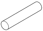
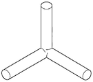
一実施形態では、コネクタは、内部が中実であり、連続的である。このようなコネクタの例が、図1A,1Bに示されている。しかし、代替例として、コネクタが、性質上、骨組みのみを有していてもよい。骨組みのコネクタは、通常、1、2、3以上の方向に延びる複数のリブを有する。好ましい一実施形態では、コネクタは、1つまたは複数の第1リブを有し、これが1つまたは複数の第2リブと交差しうる。このようなコネクタの例が、図2A,2Bに示されている。 In one embodiment, the connector is solid inside and is continuous. An example of such a connector is shown in FIGS. 1A and 1B. However, as an alternative, the connector may only have a skeleton in nature. A skeleton connector typically has a plurality of ribs extending in one, two, three or more directions. In a preferred embodiment, the connector has one or more first ribs, which can intersect one or more second ribs. An example of such a connector is shown in FIGS. 2A and 2B.
コネクタは、さまざまな材料から形成することができ、1種類の材料からも複数の材料からも形成することができる。例えば、コネクタは、ポリマー材料、金属(例えばアルミニウム、スチール、マグネシウム、金属合金)、これらの組合せなどから形成することができる。例示的なポリマー材料(例えば熱可塑性、ゴム、エラストマ、熱硬化性等)には、ポリエステル、ポリプロピレン、ポリアミド、成形コンパウンド(例えばシート成形コンパウンドまたはバルク成形コンパウンド)、ポリエチレン、ポリ塩化ビニル、ポリエチレン、これらの組合せ等が挙げられるが、ここに挙げたものに限定されない。知られているように、コネクタを形成および成形するための技術は、通常、コネクタの材料によって決まる。この技術の例としては、成形、スタンピング、ハイドロフォーミング等が挙げられるが、ここに挙げたものに限定されない。このため、コネクタは、金属スタンピング、金属鋳造(例えば金属、アルミニウム、アルミニウムフォーム、マグネシウムまたはマグネシウムフォーム鋳造)、チクソモールディングされた構造であってもよい。コネクタは、成形された(例えば注入成形、圧縮成形またはブロー成形された)プラスチック構造であってもよい。 The connector can be formed from a variety of materials, and can be formed from a single material or a plurality of materials. For example, the connector can be formed from a polymeric material, metal (eg, aluminum, steel, magnesium, metal alloy), combinations thereof, and the like. Exemplary polymeric materials (eg, thermoplastics, rubbers, elastomers, thermosets, etc.) include polyesters, polypropylenes, polyamides, molding compounds (eg, sheet molding compounds or bulk molding compounds), polyethylene, polyvinyl chloride, polyethylene, these However, it is not limited to those listed here. As is known, the technique for forming and molding the connector typically depends on the material of the connector. Examples of this technique include, but are not limited to, molding, stamping, hydroforming, and the like. For this reason, the connector may have a metal stamping, metal casting (for example, metal, aluminum, aluminum foam, magnesium or magnesium foam casting), or thixomolded structure. The connector may be a molded plastic structure (eg, injection molded, compression molded or blow molded).
本発明によるジョイントは、2つの部材、3つの部材、4つの部材、またはこれ以上を連結することができる。更に、この部材は、さまざまな構成を有することができる。通常、本発明の各部材は、コネクタの一部の近くにある先端部を有し、この部材は長尺状であり、コネクタから離れて外側に延びている。しかし、部材は、通常、金属材料から形成されるが、部材がプラスチック(例えば熱硬化性または熱可塑性材料)等のポリマー材料、または複合積層体から形成されてもよいと考察される。例示的な金属材料としては、スチール、チタン、アルミニウム、鉄、金属合金、これらの組合せ等が挙げられるが、ここに挙げたものに限定されない。 The joint according to the invention can connect two members, three members, four members or more. Further, the member can have a variety of configurations. Typically, each member of the present invention has a tip near a portion of the connector that is elongated and extends outwardly away from the connector. However, although the member is typically formed from a metallic material, it is contemplated that the member may be formed from a polymeric material such as plastic (eg, a thermosetting or thermoplastic material) or a composite laminate. Exemplary metallic materials include, but are not limited to, steel, titanium, aluminum, iron, metal alloys, combinations thereof, and the like.
本発明は、一般に、中空部材を連結するために望ましい。本明細書で使用するように、中空部材とは、開口部を有するか、または画定しているものを指す。本発明は、特に管状部材を連結するために望ましい。本明細書で使用するように、管状部材とは、開口部、より詳細にはトンネルを画定しており、これを実質的または完全に取り囲んでいるものを指す。自動車の用途では、管状部材または他の形状の部材は、ハイドロ成形された管、プレス成形された管、ロール形成された管、スタンピング、チクソモールド、押出加工(例えばアルミニウム押出加工)、鋳造、成形された(例えば注入成形、圧縮成形またはブロー成形された)部材でありえる。このため、本発明は、ジョイントを形成する方法を考察し、この方法は、部材を、事前にまたは同時に形成および/または成形する工程を有し、その際、ハイドロフォーミング、鋳造、ロール成形、スタンピング、チクソモールディング、射出成形、圧縮成形またはブロー成形の技術の1つまたは任意の組合せを使用する。 The present invention is generally desirable for connecting hollow members. As used herein, a hollow member refers to one having or defining an opening. The present invention is particularly desirable for connecting tubular members. As used herein, a tubular member refers to one that defines and substantially or completely surrounds an opening, more particularly a tunnel. In automotive applications, tubular or other shaped members can be hydroformed tubes, press formed tubes, roll formed tubes, stamping, thixo molds, extrusion (eg aluminum extrusion), casting, molding (Eg, injection molded, compression molded or blow molded). For this reason, the present invention contemplates a method of forming a joint, the method comprising the steps of forming and / or forming a member in advance or simultaneously, in which case hydroforming, casting, roll forming, stamping , Using one or any combination of thixomolding, injection molding, compression molding or blow molding techniques.
接着材料は、活性化されて膨張し、その後、硬化して、隣接する面(例えば接着面)間に強力な結合を形成する、膨張可能または発泡可能な材料であってもよい。膨張可能材料の場合、接着材料は元の非膨張時の体積に対して、好ましくは500%以下、より好ましくは100%以下、更に好ましくは50%以下の体積膨張をする。当然、本発明の範囲内で、膨張の程度がこれを越えてもよいことが考察される。また、接着材料が非膨張可能材料であってもよく、熱的に活性化されても、されなくてもよい。 The adhesive material may be an expandable or foamable material that is activated to expand and then cure to form a strong bond between adjacent surfaces (eg, adhesive surfaces). In the case of an expandable material, the adhesive material preferably has a volume expansion of 500% or less, more preferably 100% or less, and even more preferably 50% or less, with respect to the original non-expanded volume. Of course, it is contemplated that the degree of expansion may exceed this within the scope of the present invention. Also, the adhesive material may be a non-expandable material and may or may not be thermally activated.
一実施形態では、接着材料は、発泡性を有する高圧縮強度の熱活性化補強材から形成される。この材料は、ほぼ指触乾燥状態であるか粘着性を有してもよく、所望のパターン、配置または厚さの任意の形状で、部材の表面に配置されうるが、好ましくは厚さが実質的に均一である。1つの例示的な膨張可能材料は、米国ミシガン州ロメオ所在のL&L Productsから入手可能なL−5204構造発泡材である。好ましくは、接着材料の強度(例えば引張強度)は、少なくとも約5MPa、より好ましくは少なくとも約12MPa、更に好ましくは少なくとも約20MPaである。ただし、強度はこれよりも低くてもよい。 In one embodiment, the adhesive material is formed from a thermally activated reinforcement with high compressive strength that is foamable. The material may be substantially dry to the touch or sticky and can be placed on the surface of the member in any desired pattern, arrangement or thickness, but preferably has a substantial thickness. Uniform. One exemplary inflatable material is L-5204 structural foam available from L & L Products, Romeo, Michigan, USA. Preferably, the strength (eg, tensile strength) of the adhesive material is at least about 5 MPa, more preferably at least about 12 MPa, and even more preferably at least about 20 MPa. However, the strength may be lower than this.
ほかの熱活性化材料を接着材料に使用可能であるが、好ましい熱活性化材料は、膨脹可能なプラスチックであり、好ましくは発泡可能なものである。特に好ましい材料は、エポキシベースの構造発泡材である。例えば、構造発泡材は、アルファオレフィンを有しうるエチレンのコポリマーまたはターポリマーを含むエポキシベースの材料でありえるが、ここに挙げたものに限定されない。このポリマーは、コポリマーまたはターポリマーとして、2種または3種の異なるモノマー(すなわち高い化学反応性を有し、類似の分子と結合可能な小分子)から構成される。 Although other heat activated materials can be used for the adhesive material, the preferred heat activated material is an inflatable plastic, preferably one that can be foamed. A particularly preferred material is an epoxy-based structural foam. For example, the structural foam can be an epoxy-based material including, but not limited to, an ethylene copolymer or terpolymer that can have alpha olefins. This polymer is composed of two or three different monomers (ie, small molecules having high chemical reactivity and capable of binding with similar molecules) as copolymers or terpolymers.
多くのエポキシベースの構造発泡材が、当業界で公知であり、構造発泡接着材料の作製に使用することができる。代表的な構造発泡材は、エポキシ樹脂またはエチレンベースのポリマーなどのポリマー基材を含み、適切な成分(通常は膨張および硬化剤)と配合された場合、熱を加えたり、特定の環境条件が生じると、確実かつ予測可能(predicable)に膨張して硬化する。熱活性化材料に対する化学的見地から、構造発泡材は、通常、初期には、硬化前は流動可能な熱可塑性材料として処理される。材料は硬化すると架橋して、それ以上流動できなくなる。接着材料に好ましい構造発泡材調合の例に、L5206、L5207、L5208、L5209、L−5220、L−7102、L−7220、XP321、およびXP721などの名称で米国ミシガン州ロメオ所在のL&L Productsから市販されているエポキシベースの材料がある。 Many epoxy-based structural foams are known in the art and can be used to make structural foam adhesive materials. Typical structural foams include polymer substrates such as epoxy resins or ethylene-based polymers that, when combined with the appropriate ingredients (usually expansion and curing agents), can be heated or have specific environmental conditions. As it occurs, it expands and cures reliably and predicable. From a chemical standpoint for thermally activated materials, structural foams are usually initially treated as flowable thermoplastic materials prior to curing. When cured, the material crosslinks and cannot flow further. Examples of preferred structural foam formulations for adhesive materials include L5206, L5207, L5208, L5209, L-5220, L-7102, L-7220, XP321, and XP721 commercially available from L & L Products, Romeo, Michigan, USA There are epoxy based materials that have been.
本発明の一実施態様では、接着材料は、少なくとも1つのシェル/コア耐衝撃性改良剤等の強化剤を含んでいてもよい。本明細書で使用するように、「コア/シェル耐衝撃性改良剤」との用語は、その実質部分(例えば、30重量%超、50重量%超、70重量%以上)が第1のポリマー材料(すなわち第1の材料またはコア材料)を含み、これが、第2のポリマー材料(すなわち第2の材料またはシェル材料)によって実質的に完全にカプセル化されている耐衝撃性改良剤を指す。本明細書で用いられる第1のポリマー材料と第2のポリマー材料は、結合および/または反応させた(例えば、順次重合させた)1、2、3種類以上のポリマーを含んでも、あるいは、別個または同じコア/シェル系の一部であってもよい。このような材料の例は、2006年10月9日に出願された、権利者共通の米国特許出願第60/828,704号に記載されており、これは、あらゆる目的のために参照によりここに援用する。 In one embodiment of the invention, the adhesive material may include at least one reinforcing agent such as a shell / core impact modifier. As used herein, the term “core / shell impact modifier” means that a substantial portion (eg, greater than 30 wt%, greater than 50 wt%, greater than 70 wt%) of the first polymer It includes a material (ie, a first material or core material), which refers to an impact modifier that is substantially completely encapsulated by a second polymer material (ie, a second material or shell material). As used herein, the first polymeric material and the second polymeric material may comprise one, two, three or more polymers that are combined and / or reacted (eg, sequentially polymerized), or separately. Or it may be part of the same core / shell system. Examples of such materials are described in commonly owned US Patent Application No. 60 / 828,704, filed Oct. 9, 2006, which is hereby incorporated by reference for all purposes. Incorporated into.
従来の技術材料に対する好ましい接着材料の1つの利点として、好ましい材料を何通りもの方法で処理可能な点がある。好ましい材料は、射出成形、押出圧縮成形で処理するか、またはミニアプリケータによって処理できる。このため、従来技術で用いられていた材料のほとんどの機能を上回る部品設計を形成および作製することが可能である。好ましい一実施形態では、(未硬化状態の)構造発泡材は、ほぼ乾燥しているか、または比較的指触乾燥の状態にある。更に、接着材料は、部品の組み立ての前または後に、部材および/またはコネクタの接着面に塗布されうる。 One advantage of a preferred adhesive material over prior art materials is that the preferred material can be processed in a number of ways. Preferred materials can be processed by injection molding, extrusion compression molding or by a mini-applicator. Thus, it is possible to form and produce component designs that exceed most of the functions of materials used in the prior art. In a preferred embodiment, the structural foam (uncured) is substantially dry or relatively dry to the touch. Further, the adhesive material can be applied to the adhesive surface of the member and / or connector before or after assembly of the parts.
接着材料を作製するための好ましい材料について開示したが、材料が他の材料からも形成されてもよい。このような材料は、熱的に活性化されるか、あるいは環境条件(例えば水分、圧力、時間等)によって別の方法で活性化され、選択した用途に対して適切な条件下で、予測可能であり確実な方法で硬化する。このような材料の1つが、1999年3月8日に出願された本願の譲受人による米国特許第6,131,897号明細書に開示されているエポキシベースの樹脂であり、同特許の教示を参照によりここに援用する。ほかの可能な材料は、ポリオレフィン材料、少なくとも1種のモノマー型のアルファオレフィンとのコポリマーおよびターポリマー、フェノール/ホルムアルデヒド材料、フェノキシ材料、ガラス転移温度の高いポリウレタン材料などを含むが、ここに挙げたものに限定されない。また、米国特許第5,766,719号明細書、第5,755,486号明細書、第5,575,526号明細書、および第5,932,680号明細書も参照のこと(参照により援用する)。一般に、構造発泡材の望ましい特性には、剛性が比較的高いこと、高強度、ガラス転移温度が高いこと(通常>70℃)、耐食性特性が良好なことがある。このように、上記材料は、一般に、自動車メーカーが用いている材料系の妨げになることはない。 Although preferred materials for making the adhesive material have been disclosed, the material may also be formed from other materials. Such materials are thermally activated or otherwise activated by environmental conditions (eg moisture, pressure, time, etc.) and are predictable under conditions appropriate for the chosen application And is cured in a reliable manner. One such material is the epoxy-based resin disclosed in US Pat. No. 6,131,897 filed on Mar. 8, 1999 by the assignee of the present application. Is incorporated herein by reference. Other possible materials include polyolefin materials, copolymers and terpolymers with at least one monomeric type alpha olefin, phenol / formaldehyde materials, phenoxy materials, polyurethane materials with high glass transition temperatures, etc. It is not limited to things. See also US Pat. Nos. 5,766,719, 5,755,486, 5,575,526, and 5,932,680 (see also ). In general, desirable properties of structural foams include relatively high stiffness, high strength, high glass transition temperature (usually> 70 ° C.), and good corrosion resistance properties. In this way, the above materials generally do not interfere with the material system used by automobile manufacturers.
接着材料が熱により活性化される熱膨張材料である用途では、材料の選択および配合に関し考慮すべき重要な事項に、材料が反応、膨張、活性化、流動、場合によっては硬化を起こす温度がある。例えば、多くの用途では、材料が室温や、製造ラインの環境における周囲温度で反応してしまうのは望ましくない。より一般的には、材料が高温か高いレベルのエネルギーを付与された状態(塗装の準備工程など)で自動車部品と共に処理されると、自動車組立工場で使用されるような温度などの高い処理温度で、材料が反応性を示すようになる。自動車組立工場で使用される温度は約148.89℃〜204.44℃(約300°F〜400°F)であるが、車体工場および塗装工場での用途では、一般に約93.33℃(約200°F)かこれよりわずかにより高い温度である。上記の範囲以外の温度で膨張させるために、必要に応じて、発泡剤用活性剤を組成物に混合してもよい。 In applications where the adhesive material is a thermally activated thermal expansion material, an important consideration regarding material selection and formulation is the temperature at which the material reacts, expands, activates, flows, and in some cases cures. is there. For example, in many applications it is undesirable for the material to react at room temperature or at ambient temperatures in the production line environment. More generally, when a material is processed with an automotive part at a high temperature or at a high level of energy (such as a paint preparation process), a high processing temperature, such as that used in an automobile assembly plant Thus, the material becomes reactive. Temperatures used in automobile assembly plants are about 148.89 ° C. to 204.44 ° C. (about 300 ° F. to 400 ° F.), but are generally about 93.33 ° C. (for body and paint shops) About 200 ° F.) or slightly higher. In order to expand at a temperature other than the above range, an activator for a foaming agent may be mixed with the composition as necessary.
一般に、適切な材料の膨脹範囲は、約0〜1000%超である。材料の膨張の程度は、1500%以上にまで高めることができる。通常、膨張の程度が低い製品から強度が得られる。 In general, suitable materials have an expansion range of greater than about 0-1000%. The degree of material expansion can be increased to 1500% or higher. Usually, strength is obtained from a product with a low degree of expansion.
接着材料として使用可能なほかの材料は、ポリオレフィン材料、少なくとも1種のモノマー型のアルファオレフィンとのコポリマーおよびターポリマー、フェノール/ホルムアルデヒド材料、フェノキシ材料、ポリウレタンなどを含むが、ここに挙げたものに限定されない。また、米国特許第5,266,133号明細書、第5,766,719号明細書、第5,755,486号明細書、第5,575,526号明細書、第5,932,680号明細書、および国際公開第WO00/27920号パンフレット(国際特許出願第PCT/US99/24795号)も参照のこと(これら文献の全てを明示的に参照により援用する)。 Other materials that can be used as adhesive materials include polyolefin materials, copolymers and terpolymers with at least one monomeric alpha olefin, phenol / formaldehyde materials, phenoxy materials, polyurethanes, etc. It is not limited. US Pat. Nos. 5,266,133, 5,766,719, 5,755,486, 5,575,526, 5,932,680 No. and International Publication No. WO 00/27920 (International Patent Application No. PCT / US99 / 24795), all of which are expressly incorporated by reference.
別の実施形態では、材料はカプセル化または一部カプセル化された形状で提供され、接着剤のシェル内に膨脹可能な発泡可能材料がカプセル化または一部カプセル化されているペレットを含みうる。このような系の例は、権利者共通の同時係属中の米国特許出願第09/524,298号(「膨脹可能な事前成形プラグ(Exmandable Pre−Formed Plug)」)に開示されており、その内容を参照によりここに援用する。 In another embodiment, the material may be provided in an encapsulated or partially encapsulated form and may comprise pellets in which the expandable foamable material is encapsulated or partially encapsulated within an adhesive shell. An example of such a system is disclosed in co-pending U.S. patent application Ser. No. 09 / 524,298 (“Exmandable Pre-Formed Plug”), which is common to all rights holders. The contents are incorporated herein by reference.
更に、前述したように、事前に形成されたパターンを使用することもできる。その際、例えば、(平坦な面または輪郭のある面を有する)シートを押出し、次に選択した構造、パネルまたはビームに従った所定の構成に従ってダイカットして、そこに適用する。 Further, as described above, a pre-formed pattern can be used. In so doing, for example, a sheet (having a flat or contoured surface) is extruded and then die cut according to a predetermined configuration according to a selected structure, panel or beam and applied thereto.
当業者は、上記ジョイントが、従来の遮音バッフルまたは車両構造補強システムの部品と組み合わせてか、あるいはその構成要素として使用できることを認めるであろう。これは、例えば、権利者共通の同時係属中の米国特許出願第09/524,61号または第09/502,686号(参照により援用する)に開示されている。 Those skilled in the art will appreciate that the joint can be used in combination with or as a component of a conventional sound insulation baffle or vehicle structural reinforcement system. This is disclosed, for example, in co-pending U.S. Patent Application Nos. 09 / 524,61 or 09 / 502,686 (incorporated by reference).
また、本発明による接着材料は、望ましい特性を多く示しうる。本発明による接着材料は、高い延性を示す一方、比較的高い強度係数(strength moduli)を示しうる。接着材料、特に、本明細書に開示されているような成分の特定の組合せと量(例えば、特定量の付加物、耐衝撃性改良剤またはこの両方の組合せ)が、各種の望ましい特性を示しうる。これらの特性は、従来の二重重ね剪断試験法を使用して、はっきりと示される。このような方法はASTM規格の方法D3528−96(タイプA構成)に記載されており、使用試験パラメータは、試験被着体の厚さ:0.060インチ、アセトンで事前洗浄された1インチ×4インチのEG−60金属、各接着ボンドのライン:3mm、試験重なり寸法:1インチ×0.5インチ、試験速度:0.5インチ/分である。このような試験法は、望ましい特性を得るために使用することができ、このような特性には、破壊歪み(strain-to-break)をピーク時歪み(strain-at-peak)応力で割った比率(ここでは延性率と呼ぶ)、破壊時の歪みを面積計算用の端値として使用した、応力ひずみ曲線の下の面積として計算される破壊エネルギー(energy-to-beak)などがある。 Also, the adhesive material according to the present invention can exhibit many desirable properties. The adhesive material according to the invention can exhibit a high ductility while exhibiting a relatively high strength moduli. Adhesive materials, particularly certain combinations and amounts of ingredients as disclosed herein (eg, certain amounts of adducts, impact modifiers, or a combination of both) exhibit various desirable properties. sell. These properties are clearly demonstrated using conventional double lap shear test methods. Such a method is described in ASTM standard method D3528-96 (type A configuration) and the test parameters used are: thickness of test adherend: 0.060 inch, 1 inch pre-cleaned with acetone × 4 inch EG-60 metal, each adhesive bond line: 3 mm, test overlap dimension: 1 inch × 0.5 inch, test speed: 0.5 inch / min. Such a test method can be used to obtain the desired properties, such as the strain-to-break divided by the strain-at-peak stress. Such as the ratio (referred to here as the ductility factor), the energy-to-beak calculated as the area under the stress-strain curve, using the strain at failure as the end value for area calculation.
一例として、本発明の特定の接着材料は、活性化後に、約2.0超、より一般的には約2.5超、おそらく約2.8を超える延性率を示した。別の例として、本発明の特定の接着材料は、上述した試験法に従って求めた場合、活性化後に、約550Nmm超、より一般的には約700Nmm超、おそらく約750Nmmを超える破壊エネルギーの値を示した。 As an example, certain adhesive materials of the present invention exhibited a ductility factor after activation of greater than about 2.0, more typically greater than about 2.5, and perhaps greater than about 2.8. As another example, certain adhesive materials of the present invention have fracture energy values after activation that are greater than about 550 Nmm, more typically greater than about 700 Nmm, and perhaps greater than about 750 Nmm, when determined according to the test methods described above. Indicated.
更に別の例として、本発明に従って形成された特定の接着材料は、ASTM D638タイプIVの試験法によって求めた場合、活性化後に、約15MPa超、より一般的には約200MPa超、おそらく約350MPaを超える引張り係数(tensile modulus)を示した。更に、接着材料は、特に固体で提供される場合には、通常、破損(例えばチッピングなど)を受けにくくなる。 As yet another example, certain adhesive materials formed in accordance with the present invention may have greater than about 15 MPa, more typically greater than about 200 MPa, perhaps about 350 MPa after activation as determined by ASTM D638 Type IV test methods. A tensile modulus exceeding 10 is shown. Furthermore, the adhesive material is usually less susceptible to breakage (eg, chipping, etc.), particularly when provided as a solid.
図3は、本発明に従って形成された1つの例示的なジョイント10を示す。見て取れるように、ジョイント10は、第1部材14を第2部材16に相互連結するコネクタ12を有する。コネクタ12はほぼ円筒状の部材であり、第1部材14と第2部材16の両方は管状部材であるとして図示されている。
FIG. 3 illustrates one exemplary joint 10 formed in accordance with the present invention. As can be seen, the joint 10 has a
図示した実施形態では、コネクタ12は、基端部20と、中間の第1部分22および第2部分24を有する。第1部分22と第2部分24は、基端部20から逆方向に離れて、それぞれ管状部材14,16によって画定される開口部(例えばトンネル)に延びて図示されている。熱活性化可能接着材料26は、活性化されると、コネクタ12を管状部材14,16に接着するために、第1部分22と第2部分24に配置される。好ましい一実施形態では、接着材料26が、活性化後に、接着材料26と部分22,24を超えて、音または質量(例えば空気または他の物体)が管状部材14,16に侵入したり、これらが管状部材14,16から出るのを実質的に阻害または阻止することができるように、接着材料26は、活性化の前または後は、部分22,24の周りに実質的または完全に連続して延びている。
In the illustrated embodiment, the
図4乃至6も、本発明の例示的なジョイント34,36,38を示している。各ジョイント34,36,38は、基端部46から離れて延びる複数のコネクタ部分44を有するコネクタ42を有し、部分44の各々は、コネクタ42を部材52に結合するための熱活性化可能接着材料50を有する。これらの部分44の各々は、図3の部分22,24に関して記載した特徴の1つ、複数または全てを有していてもよい。
4-6 also show exemplary joints 34, 36, 38 of the present invention. Each joint 34, 36, 38 has a
図4のジョイント34は、3つの部分44を有する三方軸ジョイントであり、3つの部分44は、基端部46から離れて異なる3方向に延びており、その1、2つまたは3つの全ては、3つの部材52を連結するために、互いに角、鈍角または鋭角をなしている。また、図6のジョイント36も、3つの部材52を連結するために、基端部46から離れて延びている3つの部分44を有する。図示した部分44,46は、T字形状を形成する。図5のジョイントは、4つの部材52を連結するために、基端部46から4方向に外側に延びている4つの部分44を有する。このように、本発明のコネクタは、基端部から外側に延びている少なくとも2、3、4つ以上の部分を有しうる。
The joint 34 of FIG. 4 is a three-way joint having three
コネクタの各部は、基端部から離れて異方向に延びてもよく、その方向はそれぞれ、他の1、2、3、4つ以上の方向に対して、通常、ある角度をなしている。この角度は、一般的には約180°未満、より一般的には約170°未満、更に一般的には約140°未満、おそらく約120°未満であり、一般的には約8°超、更に一般的には約30°を超える。 Each part of the connector may extend in a different direction away from the proximal end, each of which is usually at an angle with respect to the other 1, 2, 3, 4 or more directions. This angle is typically less than about 180 °, more typically less than about 170 °, more typically less than about 140 °, perhaps less than about 120 °, typically greater than about 8 °, More generally, it exceeds about 30 °.
図3乃至6のそれぞれにおいて、図示したジョイントのコネクタは、これらが連結している部材間の実質的に唯一の構造相互連結要素として機能しうる。これらが連結している部材は、互いにほぼ直接接触していないか、あるいは直接接触していなくてもよい。更に、部材は、これら部材を相互に直接連結する溶接部を使用しないか、あるいは、間接的に連結する(部材の2つ以上に溶接された相互連結部片によってなど)溶接部を使用せずに相互連結されうる。これらの特徴は、特に自動車両等の製品にとって望ましいことがある。コネクタが連結している部材を、接触箇所で何らかの構造接続機構を使用せずに、相互に接触させることができることも考察される。このため、これらのコネクタで連結された部材は、通常は別の異なるものである。当然、特段の断りのない限り、部材は、例えば、1つ以上の追加の異なる接続部材、または部材の1つ以上の一体化された部分によって相互に連結されうる。 In each of FIGS. 3-6, the connectors of the illustrated joint can function as substantially the only structural interconnection element between the members to which they are connected. The members to which they are connected may not be in direct contact with each other or may not be in direct contact. In addition, the members do not use welds that directly connect these members to each other, or indirectly, such as by interconnecting pieces welded to two or more of the members. Can be interconnected. These features may be particularly desirable for products such as motor vehicles. It is also contemplated that the members to which the connector is coupled can be brought into contact with each other without using any structural connection mechanism at the point of contact. For this reason, the members connected by these connectors are usually different from each other. Of course, unless otherwise noted, the members may be interconnected by, for example, one or more additional different connecting members, or one or more integrated portions of the members.
上で示唆したように、本発明のジョイントは特に自動車両に有用である。このジョイントは、異種金属の部材を連結するために使用することができる。本明細書で使用するように、「金属」との用語の使用は、金属の量が少なくとも50%、75%、90%または実質的にほぼ純粋な金属であれば、非金属材料を含む材料を含む。このため、ジョイントの部材の1つが第1の金属(例えばアルミニウム)から形成され、第2部分が、第1の金属とは異なり、場合によっては第1の金属と相性の悪い第2の金属から形成されてもよい。本明細書で使用するように、相性の悪い金属の一例に、ある金属によって、別の金属の電気化学的腐食が生じる金属同士がある。このため、一実施形態では、ジョイントの第1部材が、少なくとも0.25V、より一般的には0.4V、更に一般的には1.1V、おそらく1.8V以上の電気電位または電極電位を有する第1の金属から形成され、これは、ジョイントの第2部材および/または第3部材の第2の金属の電気電位より低いことが考察される。本願の12ページに、水素電極に対する電位を決定できるように電位表が含まれており、更に本発明の部材に可能な金属の電位を示している。
As suggested above, the joints of the present invention are particularly useful in motor vehicles. This joint can be used to connect dissimilar metal members. As used herein, the use of the term “metal” includes materials that include non-metallic materials if the amount of metal is at least 50%, 75%, 90%, or substantially nearly pure metal. including. For this reason, one of the members of the joint is formed of a first metal (for example, aluminum), and the second portion is different from the first metal, and in some cases, the second metal is not compatible with the first metal. It may be formed. As used herein, one example of an incompatible metal is a metal that causes one metal to cause electrochemical corrosion of another metal. Thus, in one embodiment, the first member of the joint has an electrical potential or electrode potential of at least 0.25V, more typically 0.4V, more typically 1.1V, perhaps 1.8V or more. It is contemplated that it is formed from a first metal having a lower electrical potential than the second metal of the joint and / or the second metal of the third member. On
特に、接着材料が、このような許容誤差を吸収するために膨脹可能であるため、ジョイントは、部材のサイズに関して許容誤差の大きい部材を連結することもできる。本発明のジョイントは、車両のNVHを改善するため、堅いフレーム構造またはホワイトボディ(body in white:BIW)を車両に提供することができることも考察される。 In particular, since the adhesive material is expandable to absorb such tolerances, the joint can also connect members that have large tolerances with respect to the size of the member. It is also contemplated that the joint of the present invention can provide the vehicle with a rigid frame structure or body in white (BIW) to improve the vehicle's NVH.
本発明のジョイントは、自動車両の多くの異なる部材を連結するために使用することができる。車両設計に応じて相互に連結されうる部材の例は、ホワイトボディ部材、レール、ロッカー、車両横断部材(cross-vehicle members)、ピラー、ルーフレール、屋根はり(roof bow)、ヘッダ、ドアビームパドル、ミラーブラケット、上下のフロントボディヒンジピラーがあるが、これらに限定されない。 The joint of the present invention can be used to connect many different parts of a motor vehicle. Examples of members that can be interconnected according to vehicle design are white body members, rails, rockers, cross-vehicle members, pillars, roof rails, roof bows, headers, door beam paddles, mirrors There are brackets, upper and lower front body hinge pillars, but not limited to these.
図7を参照すると、本発明によるいくつかのジョイントが示されており、これらのジョイントは本明細書に記載した属性のいずれか、特に図3乃至6のジョイントに関して記載した属性を有しうる。更に、図7に示すように、本発明に従って連結できる部材は数多くある。ジョイント60は、上部前方レール62を車両横断ビーム64に相互連結している。ジョイント66は、上部前方レール62をAピラー68とヒンジピラー70に相互連結している。ジョイント74は、ヒンジピラー70を下部フレームレール76に相互連結している。ジョイント80は、Aピラー68をルーフレール82に相互連結している。ジョイント88は、ルーフレール82、または場合によってはこのルーフレールを有する2つの部材90を、Bピラー92に相互連結している。ジョイント96は、フレームレール76、または場合によってはこのフレームレール76を有する2つの部材100を、Bピラー92に相互連結している。ジョイント104は、ルーフレール82,90をCピラー110に相互連結している。ジョイント112は、Cピラー110を、後部上部レール116および/または後部ピラー部118に相互連結している。ジョイント122は、下部Cピラー、ホイールハウス、フロア、クロスメンバ、および上部Cピラーを、任意の組合せで相互連結している。最後に、ジョイント130は、下部フレームレール76,100、1つ以上のクロスメンバ、ホイールハウス、フロア、および下部Cピラーを、任意の組合せで相互連結している。
Referring to FIG. 7, several joints according to the present invention are shown, and these joints may have any of the attributes described herein, particularly those described with respect to the joints of FIGS. Furthermore, as shown in FIG. 7, there are many members that can be connected in accordance with the present invention. The joint 60 interconnects the
多くの場合、接着材料の接着の前に、連結対象の部材にコネクタを少なくとも一時的に取り付ける接続機構を有するコネクタを提供することが望ましい。これは、接着材料が、塗布、eコート処理または乾燥オーブン中で活性化し、コネクタと部材に接着するように構成されている場合に、特に当てはまる。このために、さまざまな接続機構を使用して、溶接、接着、インターロック、圧縮ばめ(compression fit)、締まりばめ(interference fit)などによって、コネクタを、連結対象の部材に取り付ける。 In many cases, it is desirable to provide a connector having a connection mechanism that at least temporarily attaches the connector to the member to be coupled prior to bonding of the adhesive material. This is especially true when the adhesive material is configured to activate and adhere to the connector and member in a coating, e-coat process or drying oven. For this purpose, the connector is attached to the member to be connected by welding, gluing, interlocking, compression fit, interference fit, etc. using various connection mechanisms.
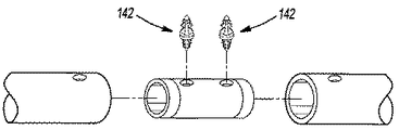
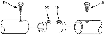
コネクタを部材に取り付けるために、機械式の接続機構またはファスナを使用することができる。機械式インターロックは、コネクタに取り付けられる(例えば、インサート成形される)か、またはコネクタと同じ材料から一体的に成型されうる。図8は、金属クリップにインサート成形された形のインターロックファスナ140を示す。図9は、部材とコネクタにある開口部に挿入するのに適した双頭プッシュピンとして示されるプッシュピンの形の、インターロックファスナ142を示す。図10は、部材の開口部を通って延びているボルト148に取り付けようとしている、コネクタ146のインサート成形されたナット144を示す。
A mechanical connection mechanism or fastener can be used to attach the connector to the member. The mechanical interlock can be attached to the connector (eg, insert molded) or integrally molded from the same material as the connector. FIG. 8 shows an
接続機構のための他の選択肢としてはエンドタブ(weld tabs)、ポップリベット、閉じ込め装置(entrapment device)、インサート成形された溶接ボタン、打ち付けプラグ(bang plug)が挙げられるが、これらに限定されない。コネクタがスタンドオフ(standoff)、回転防止装置、ポークヨーク(poke yokes)などを有してもよいことも考察される。 Other options for the connection mechanism include, but are not limited to, end tabs, pop rivets, entrapment devices, insert molded weld buttons, bang plugs. It is also contemplated that the connector may have standoffs, anti-rotation devices, poke yokes and the like.
コネクタと部材を、所望の関係で互いに対して配置したら、接着材料が、コネクタとこれが連結する部材の間に、比較的強力な結合を形成するように、構造接着材料が、好ましくは活性化され、発泡、膨張、濡れ、接着、架橋または熱硬化するか、これらの複数を起こす。 Once the connector and member are placed relative to each other in the desired relationship, the structural adhesive material is preferably activated so that the adhesive material forms a relatively strong bond between the connector and the member to which it is connected. Foam, expand, wet, bond, crosslink or heat cure, or cause multiple of these.
図3乃至7の自動車両と、自動車両用のジョイントの使用とを参照すると、構造接着材料50は、活性化して膨張(発泡するなど)し、部材52の、その部材52の全長にわたって延びる開口部を画定している内面に接触してこれを濡らし、更に、コネクタ42の表面に接触してこれを濡らす。このようにして、順に、構造接着材料は、架橋および/または熱硬化して、材料50に接着し、これにより、部材52をコネクタ24に構造的に連結する。
Referring to the motor vehicle of FIGS. 3-7 and the use of a joint for motor vehicles, the structural
このような付着および接着は、自動車両、特にホワイトボディの加工および/または組み立て中に、e−コートオーブン中で行うことができるために有利である。更に有利なことに、コネクタと接着材料は、e−コートを車両に塗布した後にこのようなジョイントを形成することができ、これにより、部材および/またはコネクタをe−コートで確実に被覆することができるようになる。 Such attachment and adhesion is advantageous because it can be performed in an e-coat oven during the processing and / or assembly of a motor vehicle, in particular a white body. Further advantageously, the connector and adhesive material can form such a joint after the e-coat has been applied to the vehicle, thereby ensuring that the member and / or connector is covered with the e-coat. Will be able to.
本発明のコネクタまたはその一部は、管状またはその他の形状に成形された部材の空洞の中に置かれ、この部材の内面に接着するものとして一般的に示した。しかし、コネクタが、管状部材または他の部材の外面に接着するように構成されてもよいことが考察される。例えば、コネクタの1つ以上の接続部分が、1つ以上の管状部材または他の形状の部材の端を受け容れるのに適した空洞を画定しており、この空洞を画定している1つ以上の内面に配置された活性化可能材料を活性化して膨張、発泡および/または部材の1つ以上の外面に接着させることができる。 The connector of the present invention or a portion thereof is generally shown as being placed in a cavity of a member molded into a tubular or other shape and adhered to the inner surface of the member. However, it is contemplated that the connector may be configured to adhere to the outer surface of a tubular member or other member. For example, one or more connecting portions of the connector define a cavity suitable for receiving the end of one or more tubular members or other shaped members, and the one or more defining the cavity The activatable material disposed on the inner surface of the member can be activated to expand, foam and / or adhere to one or more outer surfaces of the member.
特段の断りのない限り、ここに記載した各種構造の寸法および外形は本発明を限定することを意図したものではなく、ほかの寸法または外形も可能である。1つの一体化された構造により、複数の構造構成要素が提供されうる。別の実施形態では、1つの一体化された構造が、独立した複数の構成要素に分けられうる。更に、本発明の特徴を、図示した実施形態のうちの1つのみにより記載した場合もあるが、任意の用途のために、このような特徴を別の実施形態のほかの特徴の1つ以上と組み合わせることができる。また、ここに記載した独自の構造の製造およびその操作も、本発明に係る方法を構成していることが、上記から理解されよう。 Unless otherwise noted, the dimensions and outlines of the various structures described herein are not intended to limit the invention, and other dimensions or outlines are possible. A single integrated structure can provide multiple structural components. In another embodiment, one integrated structure can be divided into a plurality of independent components. Furthermore, while features of the invention may be described by only one of the illustrated embodiments, for any application, such a feature may be one or more of the other features of another embodiment. Can be combined. It will also be appreciated from the above that the manufacture and operation of the unique structure described herein also constitutes a method according to the present invention.
本発明の好ましい実施形態を開示した。しかし、当業者は、本発明の教示に特定の変更例を取り入れることができることを理解するであろう。このため、本発明の真の範囲および内容を決定するには、添付の特許請求の範囲を検討すべきである。 A preferred embodiment of the present invention has been disclosed. However, one of ordinary skill in the art appreciates that certain modifications can be incorporated into the teachings of the invention. For this reason, the following claims should be studied to determine the true scope and content of this invention.
Claims (16)
前記自動乗物の、先端部を有する第1部材を提供する工程と、
前記自動乗物の、先端部を有する第2部材を提供する工程と、
基端部と、前記基端部から離れて延びる第1部分と、前記基端部から離れて延びる第2部分と、前記第1部分および前記第2部分に配された活性化可能材料とを有するコネクタを提供する工程と、
前記第1部分を前記第1部材の前記先端部の近くに、前記第2部分を前記第2部材の前記先端部の近くに配置する工程と、
前記コネクタの前記第1部分と前記第1部材の前記先端部とに付着され、かつ前記コネクタの前記第2部分と前記第2部材の前記先端部とに付着された構造接着発泡剤を形成するために、前記活性化可能材料を活性化する工程と、を有する方法。 A method of forming a joint for an automatic vehicle,
Providing a first member of the automatic vehicle having a tip;
Providing a second member having a tip of the automatic vehicle;
A proximal end, a first portion extending away from the proximal end, a second portion extending away from the proximal end, and an activatable material disposed on the first and second portions. Providing a connector having:
Disposing the first portion near the tip of the first member and disposing the second portion near the tip of the second member;
Forming a structural adhesive foam attached to the first portion of the connector and the tip of the first member, and to the second portion of the connector and the tip of the second member; And activating the activatable material.
Applications Claiming Priority (4)
| Application Number | Priority Date | Filing Date | Title |
|---|---|---|---|
| US74681006P | 2006-05-09 | 2006-05-09 | |
| US60/746,810 | 2006-05-09 | ||
| US11/742,025 | 2007-04-30 | ||
| US11/742,025 US8163116B2 (en) | 2006-05-09 | 2007-04-30 | Joints and a system and method of forming the joints |
Publications (2)
| Publication Number | Publication Date |
|---|---|
| JP2007333208A true JP2007333208A (en) | 2007-12-27 |
| JP5273839B2 JP5273839B2 (en) | 2013-08-28 |
Family
ID=38352513
Family Applications (1)
| Application Number | Title | Priority Date | Filing Date |
|---|---|---|---|
| JP2007124048A Expired - Fee Related JP5273839B2 (en) | 2006-05-09 | 2007-05-09 | Joint, and system and method for forming the joint |
Country Status (3)
| Country | Link |
|---|---|
| US (2) | US8163116B2 (en) |
| EP (1) | EP1854704A1 (en) |
| JP (1) | JP5273839B2 (en) |
Cited By (9)
| Publication number | Priority date | Publication date | Assignee | Title |
|---|---|---|---|---|
| JP2009227188A (en) * | 2008-03-25 | 2009-10-08 | Toyota Auto Body Co Ltd | Reinforcing structure for front fender for automobile |
| JP2011213312A (en) * | 2010-04-02 | 2011-10-27 | Toyoda Gosei Co Ltd | Chassis frame |
| KR101199050B1 (en) * | 2010-08-26 | 2012-11-07 | 현대자동차주식회사 | Linkage structure of a-filla |
| KR20160095881A (en) * | 2015-02-04 | 2016-08-12 | 현대자동차주식회사 | Vehicle body member connecting member and Vehicle body member connecting using the same |
| JP2019127236A (en) * | 2018-01-26 | 2019-08-01 | イイダ産業株式会社 | Vehicle structure |
| JP2020159421A (en) * | 2019-03-26 | 2020-10-01 | 株式会社豊田中央研究所 | Frame structure and manufacturing method of frame structure |
| JP2020197307A (en) * | 2014-07-02 | 2020-12-10 | ダイバージェント テクノロジーズ, インコーポレイテッドDivergent Technologies, Inc. | Systems and methods for fabricating joint members |
| JP2021017743A (en) * | 2019-07-19 | 2021-02-15 | 清水建設株式会社 | Joint structure of component, joint method, temporary structure, and assembly/demolition method of temporary structure |
| JP2021506290A (en) * | 2017-12-18 | 2021-02-22 | エスゼット ディージェイアイ テクノロジー カンパニー リミテッドSz Dji Technology Co.,Ltd | Spray assembly and agricultural plant protector |
Families Citing this family (47)
| Publication number | Priority date | Publication date | Assignee | Title |
|---|---|---|---|---|
| US8002332B2 (en) | 2007-01-30 | 2011-08-23 | Zephyros, Inc. | Structural mounting insert |
| US8020924B2 (en) * | 2007-12-26 | 2011-09-20 | Sika Technology Ag | Integrated reinforcing crossmember |
| US8181327B2 (en) | 2008-02-08 | 2012-05-22 | Zephyros, Inc | Mechanical method for improving bond joint strength |
| US9194408B2 (en) | 2008-02-08 | 2015-11-24 | Zephyros, Inc. | Mechanical method for improving bond joint strength |
| US8293360B2 (en) * | 2008-02-27 | 2012-10-23 | Sika Technology Ag | Baffle |
| GB2457896B (en) * | 2008-02-27 | 2012-12-12 | Ifor Williams Trailers Ltd | Improved horse box trailer or other trailer |
| US8133929B2 (en) * | 2008-04-15 | 2012-03-13 | Sika Technology Ag | Method for incorporating long glass fibers into epoxy-based reinforcing resins |
| US8449701B2 (en) * | 2008-11-26 | 2013-05-28 | Dow Global Technologies Llc | Acoustic baffle members and methods for applying acoustic baffles in cavities |
| US7984919B2 (en) | 2009-05-18 | 2011-07-26 | Zephyros, Inc. | Structural mounting insert having a non-conductive isolator |
| US8870488B2 (en) * | 2009-06-19 | 2014-10-28 | Duracase Proprietary Llc | Joint assembly with reinforcing member and foam |
| ITBO20100024A1 (en) * | 2010-01-18 | 2011-07-19 | Ferrari Spa | COMPOSITE BAR FOR THE FRAME OF A VEHICLE |
| GB201012595D0 (en) | 2010-07-27 | 2010-09-08 | Zephyros Inc | Oriented structural adhesives |
| BR112013023808A2 (en) * | 2011-03-17 | 2016-12-13 | Zephyros Inc | link assembly |
| US8915530B2 (en) | 2011-07-28 | 2014-12-23 | Ford Global Technologies, Llc | Vehicle support frames with interlocking features for joining members of dissimilar materials |
| US8833832B2 (en) * | 2011-08-16 | 2014-09-16 | Ford Global Technologies, Llc | Node for connecting vehicle body portions |
| CN102963422B (en) * | 2011-08-30 | 2016-06-01 | 福特全球技术公司 | There is the vehicle support deck of the interlock feature for connecting differing materials |
| US9039061B2 (en) * | 2011-08-30 | 2015-05-26 | Ford Global Technologies, Llc | Vehicle frame assemblies with threaded connections |
| US20150021892A1 (en) * | 2013-07-22 | 2015-01-22 | GM Global Technology Operations LLC | Rail and method of making and using the same |
| EP3024871B1 (en) | 2013-07-26 | 2022-12-07 | Zephyros Inc. | Thermosetting adhesive films including a fibrous carrier |
| US10421260B2 (en) | 2013-12-17 | 2019-09-24 | Zephyros, Inc. | Carrier with localized fibrous insert and methods |
| GB201318595D0 (en) | 2013-10-21 | 2013-12-04 | Zephyros Inc | Improvements in or relating to laminates |
| BR102013028618B1 (en) * | 2013-11-06 | 2020-03-10 | Marchesan Implementos E Máquinas Agrícolas Tatú S/A | TUBULAR STRUCTURE APPLIED TO SUGAR CANE HARVEST |
| GB2521361B (en) * | 2013-12-17 | 2020-03-25 | Gordon Murray Design Ltd | Vehicle and chassis therefor |
| US10634473B2 (en) * | 2014-01-29 | 2020-04-28 | Raytheon Company | Internally coupleable joint |
| KR20170019366A (en) * | 2014-05-16 | 2017-02-21 | 디버전트 테크놀로지스, 인크. | Modular formed nodes for vehicle chassis and their methods of use |
| US11124678B2 (en) | 2015-03-25 | 2021-09-21 | L&L Products Europe Sas | Reinforcement member comprising a structural adhesive on a polyester carrier |
| CN105438266A (en) * | 2016-01-21 | 2016-03-30 | 石宇 | Wheel and beam type whole car body combined frame |
| CN105711646A (en) * | 2016-01-21 | 2016-06-29 | 石宇 | Wheel-beam combined type car frame |
| CN105599810A (en) * | 2016-01-23 | 2016-05-25 | 石宇 | Wheel beam type multi-wheel combination frame |
| CN105691456A (en) * | 2016-01-24 | 2016-06-22 | 石宇 | Wheel beam type axle-free vehicle frame |
| DE102016001241A1 (en) * | 2016-02-04 | 2017-08-10 | GM Global Technology Operations LLC (n. d. Ges. d. Staates Delaware) | Structure node for a motor vehicle body |
| US9988093B2 (en) * | 2016-09-28 | 2018-06-05 | Ford Global Technologies, Llc | Exoskeleton vehicle upper body structure |
| CN107061443B (en) * | 2016-12-31 | 2019-04-05 | 石恬瑜 | A kind of carbon fibre composite grafting connector |
| US10183706B2 (en) * | 2017-01-20 | 2019-01-22 | Caterpillar Inc. | Nodes for frame structures |
| EP3583161B1 (en) | 2017-02-17 | 2021-09-01 | Zephyros Inc. | Activatable polymer composition comprising at least two carboxylic acids as blowing agent |
| US10106204B2 (en) * | 2017-02-23 | 2018-10-23 | Ford Global Technologies, Llc | Vehicle joint assembly with expandable structural material |
| CN106864595B (en) * | 2017-04-10 | 2021-02-09 | 上海蔚来汽车有限公司 | A connecting piece, frame subassembly and electric automobile for frame |
| FR3068948A1 (en) * | 2017-07-12 | 2019-01-18 | Compagnie Plastic Omnium | FRONT MODULE FOR VEHICLE |
| US11306751B2 (en) * | 2017-08-31 | 2022-04-19 | Divergent Technologies, Inc. | Apparatus and methods for connecting tubes in transport structures |
| KR102586882B1 (en) * | 2018-03-09 | 2023-10-10 | 에이치디현대인프라코어 주식회사 | Canopy assembly of construction machinery |
| US20190391563A1 (en) * | 2018-06-22 | 2019-12-26 | Divergent Technologies, Inc. | Additive manufacturing-enabled platform for modular construction of vehicles using definition nodes |
| KR102107967B1 (en) * | 2018-11-26 | 2020-05-07 | 한국생산기술연구원 | A Joint Material for Chassis Frame and Variable type Chassis Module of Vehicle using the same |
| CN110816686A (en) * | 2019-12-25 | 2020-02-21 | 吉林大学 | Special cast aluminum joint for aluminum alloy vehicle body frame |
| KR20220021612A (en) * | 2020-08-14 | 2022-02-22 | 현대자동차주식회사 | Vehicle body of vehicle |
| EP4032755A1 (en) * | 2021-01-26 | 2022-07-27 | Volvo Construction Equipment AB | Support structure for a vehicle and method for assembling parts of a support structure for a vehicle |
| EP4284861A1 (en) | 2021-01-27 | 2023-12-06 | Zephyros Inc. | Low odor heat-expandable materials |
| WO2023247584A1 (en) | 2022-06-24 | 2023-12-28 | Zephyros, Inc. | Thermal runaway fumes management |
Citations (8)
| Publication number | Priority date | Publication date | Assignee | Title |
|---|---|---|---|---|
| JPS5027753A (en) * | 1973-07-14 | 1975-03-22 | ||
| JPH0173512U (en) * | 1987-11-06 | 1989-05-18 | ||
| JPH01131312A (en) * | 1987-11-12 | 1989-05-24 | Miyata Ind Co Ltd | Pipe joint |
| JP2000219152A (en) * | 1999-01-29 | 2000-08-08 | Mazda Motor Corp | Body structure for vehicle and its manufacture |
| JP2001278162A (en) * | 2000-03-31 | 2001-10-10 | Miyata Ind Co Ltd | Method of jointing frame pipe for bicycle |
| JP2002005136A (en) * | 2000-06-22 | 2002-01-09 | Pica Corp | Joining structure and joining method of pipe member and joint |
| JP2003528736A (en) * | 2000-04-03 | 2003-09-30 | コラス・スタール・ベー・ブイ | Process of manufacturing tubular parts |
| JP2005155762A (en) * | 2003-11-25 | 2005-06-16 | Inoue Shoji Kk | Pipe joint and structure of the same |
Family Cites Families (35)
| Publication number | Priority date | Publication date | Assignee | Title |
|---|---|---|---|---|
| US1958835A (en) * | 1930-10-28 | 1934-05-15 | Alabama Pipe Company | Pipe |
| US4050721A (en) * | 1976-06-09 | 1977-09-27 | Phone-Ducs, Inc. | Reinforced plastic pipe |
| US5290857A (en) * | 1991-09-04 | 1994-03-01 | Nippon Zeon Co., Ltd. | Epoxy resin adhesive composition |
| US5266133A (en) * | 1993-02-17 | 1993-11-30 | Sika Corporation | Dry expansible sealant and baffle composition and product |
| JP3655646B2 (en) * | 1993-05-24 | 2005-06-02 | 日産自動車株式会社 | Adhesive reinforcing agent for epoxy resin and epoxy resin-based structural adhesive composition for automobile containing the reinforcing agent |
| US5458393A (en) * | 1993-08-11 | 1995-10-17 | Alumax Extrusions, Inc. | Space frame apparatus and process for the manufacture of same |
| US5932680A (en) * | 1993-11-16 | 1999-08-03 | Henkel Kommanditgesellschaft Auf Aktien | Moisture-curing polyurethane hot-melt adhesive |
| EP0679501A1 (en) * | 1994-03-14 | 1995-11-02 | YMOS AKTIENGESELLSCHAFT Industrieprodukte | Composite material with foamable core |
| US5575526A (en) * | 1994-05-19 | 1996-11-19 | Novamax Technologies, Inc. | Composite laminate beam for radiator support |
| US5755486A (en) * | 1995-05-23 | 1998-05-26 | Novamax Technologies Holdings, Inc. | Composite structural reinforcement member |
| US6068424A (en) * | 1998-02-04 | 2000-05-30 | Henkel Corporation | Three dimensional composite joint reinforcement for an automotive vehicle |
| US6387470B1 (en) | 1998-11-05 | 2002-05-14 | Sika Corporation | Sound deadening and structural reinforcement compositions and methods of using the same |
| US6131897A (en) * | 1999-03-16 | 2000-10-17 | L & L Products, Inc. | Structural reinforcements |
| DE19929057B4 (en) * | 1999-06-25 | 2005-03-31 | Daimlerchrysler Ag | Vehicle support structure and method for its manufacture |
| US6467834B1 (en) * | 2000-02-11 | 2002-10-22 | L&L Products | Structural reinforcement system for automotive vehicles |
| US6422575B1 (en) * | 2000-03-14 | 2002-07-23 | L&L Products, Inc. | Expandable pre-formed plug |
| US6482486B1 (en) * | 2000-03-14 | 2002-11-19 | L&L Products | Heat activated reinforcing sleeve |
| US6523857B1 (en) * | 2000-07-05 | 2003-02-25 | Sika Corporation | Reinforcing member for interfitting channels |
| DE10032556B4 (en) * | 2000-07-05 | 2010-06-10 | Volkswagen Ag | Method for producing a body component in sandwich construction and apparatus for carrying out the method |
| DE10117124A1 (en) * | 2001-04-06 | 2002-10-10 | Henniges Elastomer Kunststoff | Method and device for butt-jointing profiles made of elastomeric material |
| DE10123946B4 (en) * | 2001-05-17 | 2004-11-25 | Benteler Automobiltechnik Gmbh | fuse element |
| US20030192643A1 (en) * | 2002-03-15 | 2003-10-16 | Rainer Schoenfeld | Epoxy adhesive having improved impact resistance |
| JP4052566B2 (en) * | 2002-09-05 | 2008-02-27 | 本田技研工業株式会社 | Frame coupling structure and coupling method |
| US7105112B2 (en) * | 2002-11-05 | 2006-09-12 | L&L Products, Inc. | Lightweight member for reinforcing, sealing or baffling |
| CA2455286A1 (en) * | 2003-01-16 | 2004-07-16 | Dana Corporation | Cast aluminum node for connecting vehicle frame members and method of manufacturing same |
| JP4467040B2 (en) * | 2003-09-12 | 2010-05-26 | 本田技研工業株式会社 | Filling structure |
| DE10359785A1 (en) * | 2003-12-19 | 2005-07-21 | Daimlerchrysler Ag | Attachment for mounting on motor vehicle, has connecting member cast in thin-walled portion of cast part |
| US7251915B2 (en) * | 2004-09-10 | 2007-08-07 | Pullman Industries, Inc. | Frame system for motor vehicle |
| JP2006158792A (en) * | 2004-12-09 | 2006-06-22 | Sri Sports Ltd | Golf club shaft |
| GB0506513D0 (en) * | 2005-03-31 | 2005-05-04 | L & L Products Inc | Improvements in or relating to joints |
| US7892396B2 (en) * | 2006-06-07 | 2011-02-22 | Zephyros, Inc. | Toughened activatable material for sealing, baffling or reinforcing and method of forming same |
| US7993071B2 (en) * | 2006-10-25 | 2011-08-09 | Burrell E. Clawson | Assemblies for coupling two elements and coupled assemblies |
| US8082667B2 (en) * | 2007-05-31 | 2011-12-27 | The Boeing Company | Apparatus and methods for securing a first structural member and a second structural member to one another |
| US7712993B2 (en) * | 2007-11-30 | 2010-05-11 | The Boeing Company | Double shear joint for bonding in structural applications |
| US8181327B2 (en) * | 2008-02-08 | 2012-05-22 | Zephyros, Inc | Mechanical method for improving bond joint strength |
-
2007
- 2007-04-30 US US11/742,025 patent/US8163116B2/en active Active
- 2007-05-08 EP EP07009213A patent/EP1854704A1/en not_active Withdrawn
- 2007-05-09 JP JP2007124048A patent/JP5273839B2/en not_active Expired - Fee Related
-
2012
- 2012-04-10 US US13/443,316 patent/US20120205029A1/en not_active Abandoned
Patent Citations (8)
| Publication number | Priority date | Publication date | Assignee | Title |
|---|---|---|---|---|
| JPS5027753A (en) * | 1973-07-14 | 1975-03-22 | ||
| JPH0173512U (en) * | 1987-11-06 | 1989-05-18 | ||
| JPH01131312A (en) * | 1987-11-12 | 1989-05-24 | Miyata Ind Co Ltd | Pipe joint |
| JP2000219152A (en) * | 1999-01-29 | 2000-08-08 | Mazda Motor Corp | Body structure for vehicle and its manufacture |
| JP2001278162A (en) * | 2000-03-31 | 2001-10-10 | Miyata Ind Co Ltd | Method of jointing frame pipe for bicycle |
| JP2003528736A (en) * | 2000-04-03 | 2003-09-30 | コラス・スタール・ベー・ブイ | Process of manufacturing tubular parts |
| JP2002005136A (en) * | 2000-06-22 | 2002-01-09 | Pica Corp | Joining structure and joining method of pipe member and joint |
| JP2005155762A (en) * | 2003-11-25 | 2005-06-16 | Inoue Shoji Kk | Pipe joint and structure of the same |
Cited By (13)
| Publication number | Priority date | Publication date | Assignee | Title |
|---|---|---|---|---|
| JP2009227188A (en) * | 2008-03-25 | 2009-10-08 | Toyota Auto Body Co Ltd | Reinforcing structure for front fender for automobile |
| JP2011213312A (en) * | 2010-04-02 | 2011-10-27 | Toyoda Gosei Co Ltd | Chassis frame |
| KR101199050B1 (en) * | 2010-08-26 | 2012-11-07 | 현대자동차주식회사 | Linkage structure of a-filla |
| JP2020197307A (en) * | 2014-07-02 | 2020-12-10 | ダイバージェント テクノロジーズ, インコーポレイテッドDivergent Technologies, Inc. | Systems and methods for fabricating joint members |
| KR20160095881A (en) * | 2015-02-04 | 2016-08-12 | 현대자동차주식회사 | Vehicle body member connecting member and Vehicle body member connecting using the same |
| KR101655195B1 (en) * | 2015-02-04 | 2016-09-22 | 현대자동차 주식회사 | Vehicle body member connecting member and Vehicle body member connecting using the same |
| JP2021506290A (en) * | 2017-12-18 | 2021-02-22 | エスゼット ディージェイアイ テクノロジー カンパニー リミテッドSz Dji Technology Co.,Ltd | Spray assembly and agricultural plant protector |
| JP2019127236A (en) * | 2018-01-26 | 2019-08-01 | イイダ産業株式会社 | Vehicle structure |
| JP7123365B2 (en) | 2018-01-26 | 2022-08-23 | イイダ産業株式会社 | vehicle structure |
| JP2020159421A (en) * | 2019-03-26 | 2020-10-01 | 株式会社豊田中央研究所 | Frame structure and manufacturing method of frame structure |
| JP7201228B2 (en) | 2019-03-26 | 2023-01-10 | 株式会社豊田中央研究所 | Frame structure and method for manufacturing frame structure |
| JP2021017743A (en) * | 2019-07-19 | 2021-02-15 | 清水建設株式会社 | Joint structure of component, joint method, temporary structure, and assembly/demolition method of temporary structure |
| JP7409796B2 (en) | 2019-07-19 | 2024-01-09 | 清水建設株式会社 | Joining structure of members, joining method, temporary structure, and assembly and disassembly method of temporary structure |
Also Published As
| Publication number | Publication date |
|---|---|
| EP1854704A1 (en) | 2007-11-14 |
| US8163116B2 (en) | 2012-04-24 |
| JP5273839B2 (en) | 2013-08-28 |
| US20070281523A1 (en) | 2007-12-06 |
| US20120205029A1 (en) | 2012-08-16 |
Similar Documents
| Publication | Publication Date | Title |
|---|---|---|
| JP5273839B2 (en) | Joint, and system and method for forming the joint | |
| CA2440094C (en) | Structural reinforcement member and method of use therefor | |
| US6502821B2 (en) | Automotive body panel damping system | |
| US7114763B2 (en) | Automotive rail/frame energy management system | |
| US6729425B2 (en) | Adjustable reinforced structural assembly and method of use therefor | |
| US6920693B2 (en) | Dynamic self-adjusting assembly for sealing, baffling or structural reinforcement | |
| US6969551B2 (en) | Method and assembly for fastening and reinforcing a structural member | |
| US6561571B1 (en) | Structurally enhanced attachment of a reinforcing member | |
| US6523884B2 (en) | Hydroform structural reinforcement system | |
| US6474723B2 (en) | Heat activated reinforcing sleeve | |
| US20050230165A1 (en) | Baffle for an automotive vehicle and method of use therefor | |
| US20040034982A1 (en) | System and method for sealing, baffling or reinforcing | |
| US20020024233A1 (en) | Vibrational reduction system for automotive vehicles | |
| US20080202674A1 (en) | Structural reinforcements | |
| JP2005508797A (en) | Composite structural member for automobile having predetermined impact energy absorption | |
| US8381403B2 (en) | Baffle for an automotive vehicle and method of use therefor |
Legal Events
| Date | Code | Title | Description |
|---|---|---|---|
| A621 | Written request for application examination |
Free format text: JAPANESE INTERMEDIATE CODE: A621 Effective date: 20100507 |
|
| A977 | Report on retrieval |
Free format text: JAPANESE INTERMEDIATE CODE: A971007 Effective date: 20120625 |
|
| A131 | Notification of reasons for refusal |
Free format text: JAPANESE INTERMEDIATE CODE: A131 Effective date: 20120731 |
|
| A521 | Written amendment |
Free format text: JAPANESE INTERMEDIATE CODE: A523 Effective date: 20121031 |
|
| TRDD | Decision of grant or rejection written | ||
| A01 | Written decision to grant a patent or to grant a registration (utility model) |
Free format text: JAPANESE INTERMEDIATE CODE: A01 Effective date: 20130507 |
|
| A61 | First payment of annual fees (during grant procedure) |
Free format text: JAPANESE INTERMEDIATE CODE: A61 Effective date: 20130513 |
|
| R150 | Certificate of patent or registration of utility model |
Free format text: JAPANESE INTERMEDIATE CODE: R150 |
|
| LAPS | Cancellation because of no payment of annual fees |