JP2007294103A - Objective lens and optical pickup apparatus - Google Patents
Objective lens and optical pickup apparatus Download PDFInfo
- Publication number
- JP2007294103A JP2007294103A JP2007166230A JP2007166230A JP2007294103A JP 2007294103 A JP2007294103 A JP 2007294103A JP 2007166230 A JP2007166230 A JP 2007166230A JP 2007166230 A JP2007166230 A JP 2007166230A JP 2007294103 A JP2007294103 A JP 2007294103A
- Authority
- JP
- Japan
- Prior art keywords
- objective lens
- pickup device
- optical pickup
- lens
- optical
- Prior art date
- Legal status (The legal status is an assumption and is not a legal conclusion. Google has not performed a legal analysis and makes no representation as to the accuracy of the status listed.)
- Granted
Links
- 230000003287 optical effect Effects 0.000 title claims abstract description 408
- 230000004075 alteration Effects 0.000 claims description 207
- 230000008878 coupling Effects 0.000 claims description 165
- 238000010168 coupling process Methods 0.000 claims description 165
- 238000005859 coupling reaction Methods 0.000 claims description 165
- 239000011241 protective layer Substances 0.000 claims description 31
- 239000000463 material Substances 0.000 claims description 29
- 230000008859 change Effects 0.000 claims description 24
- 229920003023 plastic Polymers 0.000 claims description 22
- 239000004033 plastic Substances 0.000 claims description 22
- 230000010355 oscillation Effects 0.000 claims description 11
- 230000015572 biosynthetic process Effects 0.000 claims description 5
- 239000002131 composite material Substances 0.000 claims description 5
- 239000011521 glass Substances 0.000 claims description 5
- 238000003786 synthesis reaction Methods 0.000 claims description 5
- 230000007423 decrease Effects 0.000 claims description 3
- 238000010586 diagram Methods 0.000 description 64
- 206010010071 Coma Diseases 0.000 description 15
- 230000009471 action Effects 0.000 description 14
- 230000035945 sensitivity Effects 0.000 description 10
- 239000004065 semiconductor Substances 0.000 description 9
- 230000006866 deterioration Effects 0.000 description 8
- 239000000758 substrate Substances 0.000 description 7
- 230000007246 mechanism Effects 0.000 description 4
- 230000002542 deteriorative effect Effects 0.000 description 3
- 238000004904 shortening Methods 0.000 description 3
- 235000008694 Humulus lupulus Nutrition 0.000 description 2
- 238000010521 absorption reaction Methods 0.000 description 2
- 230000015556 catabolic process Effects 0.000 description 2
- 238000006243 chemical reaction Methods 0.000 description 2
- 238000006731 degradation reaction Methods 0.000 description 2
- 229920006395 saturated elastomer Polymers 0.000 description 2
- 230000003595 spectral effect Effects 0.000 description 2
- 238000002834 transmittance Methods 0.000 description 2
- XLYOFNOQVPJJNP-UHFFFAOYSA-N water Substances O XLYOFNOQVPJJNP-UHFFFAOYSA-N 0.000 description 2
- 239000013585 weight reducing agent Substances 0.000 description 2
- KTTCLOUATPWTNB-UHFFFAOYSA-N 2-[2-[4-(6,7-dimethoxy-3,4-dihydro-1h-isoquinolin-2-yl)butylcarbamoyl]-4-methylphenoxy]ethyl methanesulfonate Chemical compound C1C=2C=C(OC)C(OC)=CC=2CCN1CCCCNC(=O)C1=CC(C)=CC=C1OCCOS(C)(=O)=O KTTCLOUATPWTNB-UHFFFAOYSA-N 0.000 description 1
- 201000009310 astigmatism Diseases 0.000 description 1
- 230000008901 benefit Effects 0.000 description 1
- 230000000694 effects Effects 0.000 description 1
- 230000004907 flux Effects 0.000 description 1
- 238000004519 manufacturing process Methods 0.000 description 1
- 238000012544 monitoring process Methods 0.000 description 1
- 238000000465 moulding Methods 0.000 description 1
- JFNLZVQOOSMTJK-KNVOCYPGSA-N norbornene Chemical compound C1[C@@H]2CC[C@H]1C=C2 JFNLZVQOOSMTJK-KNVOCYPGSA-N 0.000 description 1
- 230000002093 peripheral effect Effects 0.000 description 1
- 229920000098 polyolefin Polymers 0.000 description 1
- 229920005672 polyolefin resin Polymers 0.000 description 1
- 229920005989 resin Polymers 0.000 description 1
- 239000011347 resin Substances 0.000 description 1
- 230000007704 transition Effects 0.000 description 1
Images


Classifications
-
- G—PHYSICS
- G11—INFORMATION STORAGE
- G11B—INFORMATION STORAGE BASED ON RELATIVE MOVEMENT BETWEEN RECORD CARRIER AND TRANSDUCER
- G11B7/00—Recording or reproducing by optical means, e.g. recording using a thermal beam of optical radiation by modifying optical properties or the physical structure, reproducing using an optical beam at lower power by sensing optical properties; Record carriers therefor
- G11B7/12—Heads, e.g. forming of the optical beam spot or modulation of the optical beam
- G11B7/135—Means for guiding the beam from the source to the record carrier or from the record carrier to the detector
- G11B7/1353—Diffractive elements, e.g. holograms or gratings
-
- G—PHYSICS
- G02—OPTICS
- G02B—OPTICAL ELEMENTS, SYSTEMS OR APPARATUS
- G02B13/00—Optical objectives specially designed for the purposes specified below
- G02B13/18—Optical objectives specially designed for the purposes specified below with lenses having one or more non-spherical faces, e.g. for reducing geometrical aberration
-
- G—PHYSICS
- G11—INFORMATION STORAGE
- G11B—INFORMATION STORAGE BASED ON RELATIVE MOVEMENT BETWEEN RECORD CARRIER AND TRANSDUCER
- G11B7/00—Recording or reproducing by optical means, e.g. recording using a thermal beam of optical radiation by modifying optical properties or the physical structure, reproducing using an optical beam at lower power by sensing optical properties; Record carriers therefor
- G11B7/12—Heads, e.g. forming of the optical beam spot or modulation of the optical beam
- G11B7/135—Means for guiding the beam from the source to the record carrier or from the record carrier to the detector
- G11B7/1372—Lenses
- G11B7/1374—Objective lenses
-
- G—PHYSICS
- G11—INFORMATION STORAGE
- G11B—INFORMATION STORAGE BASED ON RELATIVE MOVEMENT BETWEEN RECORD CARRIER AND TRANSDUCER
- G11B7/00—Recording or reproducing by optical means, e.g. recording using a thermal beam of optical radiation by modifying optical properties or the physical structure, reproducing using an optical beam at lower power by sensing optical properties; Record carriers therefor
- G11B7/12—Heads, e.g. forming of the optical beam spot or modulation of the optical beam
- G11B7/135—Means for guiding the beam from the source to the record carrier or from the record carrier to the detector
- G11B7/1392—Means for controlling the beam wavefront, e.g. for correction of aberration
- G11B7/13922—Means for controlling the beam wavefront, e.g. for correction of aberration passive
-
- G—PHYSICS
- G02—OPTICS
- G02B—OPTICAL ELEMENTS, SYSTEMS OR APPARATUS
- G02B27/00—Optical systems or apparatus not provided for by any of the groups G02B1/00 - G02B26/00, G02B30/00
- G02B27/0025—Optical systems or apparatus not provided for by any of the groups G02B1/00 - G02B26/00, G02B30/00 for optical correction, e.g. distorsion, aberration
- G02B27/0031—Optical systems or apparatus not provided for by any of the groups G02B1/00 - G02B26/00, G02B30/00 for optical correction, e.g. distorsion, aberration for scanning purposes
-
- G—PHYSICS
- G02—OPTICS
- G02B—OPTICAL ELEMENTS, SYSTEMS OR APPARATUS
- G02B27/00—Optical systems or apparatus not provided for by any of the groups G02B1/00 - G02B26/00, G02B30/00
- G02B27/0025—Optical systems or apparatus not provided for by any of the groups G02B1/00 - G02B26/00, G02B30/00 for optical correction, e.g. distorsion, aberration
- G02B27/0037—Optical systems or apparatus not provided for by any of the groups G02B1/00 - G02B26/00, G02B30/00 for optical correction, e.g. distorsion, aberration with diffracting elements
-
- G—PHYSICS
- G11—INFORMATION STORAGE
- G11B—INFORMATION STORAGE BASED ON RELATIVE MOVEMENT BETWEEN RECORD CARRIER AND TRANSDUCER
- G11B7/00—Recording or reproducing by optical means, e.g. recording using a thermal beam of optical radiation by modifying optical properties or the physical structure, reproducing using an optical beam at lower power by sensing optical properties; Record carriers therefor
- G11B7/12—Heads, e.g. forming of the optical beam spot or modulation of the optical beam
- G11B7/135—Means for guiding the beam from the source to the record carrier or from the record carrier to the detector
- G11B7/1372—Lenses
- G11B2007/13727—Compound lenses, i.e. two or more lenses co-operating to perform a function, e.g. compound objective lens including a solid immersion lens, positive and negative lenses either bonded together or with adjustable spacing
Landscapes
- Physics & Mathematics (AREA)
- Optics & Photonics (AREA)
- General Physics & Mathematics (AREA)
- Lenses (AREA)
- Optical Head (AREA)
- Microscoopes, Condenser (AREA)
- Mechanical Optical Scanning Systems (AREA)
- Facsimile Heads (AREA)
- Testing Of Coins (AREA)
- Photo Coupler, Interrupter, Optical-To-Optical Conversion Devices (AREA)
Abstract
Description
本発明は、光ディスクなどの光情報記録媒体に、記録又は再生を行う光学式記録再生装置のピックアップ用対物レンズ、この対物レンズを使用する光ピックアップ装置、及びこの光ピックアップ装置を備えた光情報記録媒体の記録/再生装置に関する。 The present invention relates to a pickup objective lens of an optical recording / reproducing apparatus that performs recording or reproduction on an optical information recording medium such as an optical disc, an optical pickup apparatus that uses this objective lens, and an optical information recording apparatus that includes this optical pickup apparatus. The present invention relates to a medium recording / reproducing apparatus.
光ディスクなどを媒体とした光学式記録再生装置の光学系において、非球面単玉対物レンズが広く用いられているが、記録情報信号の高密度化を図るため、対物レンズが記録媒体上に集光するスポットを小さくすることが要求されており、対物レンズの高NA化とともに短波長光源の利用が検討されつつある。 In an optical system of an optical recording / reproducing apparatus using an optical disk as a medium, an aspherical single objective lens is widely used. However, in order to increase the density of recorded information signals, the objective lens is focused on the recording medium. Therefore, the use of a short wavelength light source is being studied along with an increase in NA of the objective lens.
レーザの短波長化や対物レンズの高NA化が図られてくると、CDやDVDのごとき従来の光ディスクに対して情報の記録又は再生を行うような比較的長波長のレーザと低NAの対物レンズとの組み合わせからなる光ピックアップ装置ではほとんど無視できる問題でもより顕在化されることが予想される。その一つが、半導体レーザの微少な発振波長のずれにより対物レンズで生じる軸上色収差の問題である。一般のレンズ材料の微少な波長変動による屈折率変化は、短波長を取り扱うほど大きくなる。その結果、焦点のデフォーカス量が大きくなる。ところが、対物レンズの焦点深度は、kλ/NA2(kは比例定数,λは波長,NAは対物レンズの開口数)で表されることからわかるように、使用波長が短いほど焦点深度が小さくなり、僅かなデフォー力ス量も許されない。従って、GaN系半導体レーザのような短波長の光源及び高NAの対物レンズを用いた光学系では、モードホップ現象及びレーザ出力変化による波長変動や高周波重畳による波面収差の劣化を防ぐために、軸上色収差の補正が重要となる。 When lasers have shorter wavelengths and higher objective lens NAs, relatively long wavelength lasers and low NA objectives that record or reproduce information on conventional optical discs such as CDs and DVDs. In an optical pickup device composed of a combination with a lens, it is expected that even a problem that can be almost ignored will become more apparent. One of them is a problem of longitudinal chromatic aberration generated in the objective lens due to a slight deviation of the oscillation wavelength of the semiconductor laser. A change in refractive index due to a minute wavelength variation of a general lens material increases as a short wavelength is handled. As a result, the focus defocus amount increases. However, as can be seen from the fact that the focal depth of the objective lens is expressed by kλ / NA 2 (k is a proportional constant, λ is the wavelength, and NA is the numerical aperture of the objective lens), the shorter the wavelength used, the smaller the focal depth. Therefore, a slight amount of default force is not allowed. Therefore, in an optical system using a short-wavelength light source such as a GaN-based semiconductor laser and a high-NA objective lens, in order to prevent wavelength fluctuation due to mode hopping phenomenon and laser output change and deterioration of wavefront aberration due to high frequency superposition, Correction of chromatic aberration is important.
更に、レーザの短波長化と対物レンズの高NA化の組み合わせにおいて顕在化する別な問題は、温度・湿度変化による光学系の球面収差の変動である。すなわち、光ピックアップ装置において一般的に使用されているプレスチックレンズは温度や湿度変化を受けて変形しやすく、また、屈折率が大きく変化する。従来の光ピックアップ装置では問題にならなかった屈折率変化による球面収差の変動も、レーザの短波長化と対物レンズの高NA化の組み合わせにおいては、無視できない量となる。 Furthermore, another problem that becomes apparent in the combination of shortening the wavelength of the laser and increasing the NA of the objective lens is the fluctuation of the spherical aberration of the optical system due to temperature and humidity changes. That is, a plastic lens generally used in an optical pickup device is easily deformed by changes in temperature and humidity, and its refractive index changes greatly. The variation of spherical aberration due to the change in refractive index, which has not been a problem in the conventional optical pickup device, is a non-negligible amount in the combination of shortening the laser wavelength and increasing the NA of the objective lens.
更に、レーザの短波長化と対物レンズの高NA化の組み合わせにおいて顕在化する別な問題は、光ディスクの保護層の厚み誤差に起因する光学系の球面収差の変動である。保護層の厚み誤差により生じる球面収差は、対物レンズのNAの4乗に比例して発生することが知られている。従って、対物レンズのNAが大きくなるにつれて保護層の厚み誤差の影響が大きくなり、安定した情報の記録/再生が出来なくなる恐れがある。 Furthermore, another problem that becomes apparent in the combination of shortening the wavelength of the laser and increasing the NA of the objective lens is a variation in the spherical aberration of the optical system due to the thickness error of the protective layer of the optical disk. It is known that the spherical aberration caused by the thickness error of the protective layer is generated in proportion to the fourth power of the NA of the objective lens. Therefore, as the NA of the objective lens increases, the influence of the thickness error of the protective layer increases, and there is a possibility that stable information recording / reproduction cannot be performed.
光ディスク用の非球面単玉対物レンズでは、非球面によって球面収差とコマ収差を補正するが、開口数が大きくなると、像高特性が劣化してしまう。光ディスクの高密度化が進むにつれ、像高特性の劣化は、たとえ小きな値であっても、非常に大きな問題となってしまう。特に、開ロ数が0.65以上になると、問題が顕著となる。また、開口数が大きくなると、偏心感度の劣化も大きな問題となる。 In an aspherical single objective lens for an optical disk, spherical aberration and coma are corrected by the aspherical surface. However, when the numerical aperture is increased, image height characteristics are degraded. As the density of optical discs increases, deterioration in image height characteristics becomes a very serious problem even if the value is small. In particular, when the open number is 0.65 or more, the problem becomes significant. In addition, when the numerical aperture increases, deterioration of the eccentricity sensitivity becomes a serious problem.
本発明は、前記課題を解決するためになされたものである。即ち、光ピックアップ装置用の対物レンズにおいて、開口数が大きく、像高特性の良い非球面単玉対物レンズを提供することを目的とする。特に、開口数が0.65以上、好ましくは0.70以上、更に好ましくは0.75以上と大きく、また光源の波長が400nm程度と短い波長のレーザを使用する高密度記録再生装置に用いるのに好適な、対物レンズを提供することを目的とする。また、偏心感度を良好にする対物レンズを提供することも本発明の目的である。また、球面収差やコマ収差を良好にする対物レンズを提供することも本発明の目的である。 The present invention has been made to solve the above problems. That is, an object of the present invention is to provide an aspherical single objective lens having a large numerical aperture and good image height characteristics in an objective lens for an optical pickup device. In particular, it is used for a high-density recording / reproducing apparatus using a laser having a large numerical aperture of 0.65 or more, preferably 0.70 or more, more preferably 0.75 or more and a light source wavelength of about 400 nm. An object of the present invention is to provide an objective lens suitable for the above. It is also an object of the present invention to provide an objective lens with good decentration sensitivity. It is also an object of the present invention to provide an objective lens that improves spherical aberration and coma.
また、光情報記録媒体の保護層(透明基板)の厚さが0.2mm程度やそれ以下と薄い場合、または保護層がない場合に、ワーキングディスタンスが小さくても良いが、そのようなワーキングディスタンスの小さい記録再生装置に用いられるのに好適な対物レンズを提供することを目的とする。 In addition, the working distance may be small when the thickness of the protective layer (transparent substrate) of the optical information recording medium is as thin as about 0.2 mm or less, or when there is no protective layer, but such a working distance may be small. An object of the present invention is to provide an objective lens suitable for use in a recording / reproducing apparatus having a small size.
また、これらの対物レンズを使用する光ピックアップ装置や光情報記録媒体の記録/再生装置を提供することを目的とする。 It is another object of the present invention to provide an optical pickup device using these objective lenses and a recording / reproducing device for an optical information recording medium.
また、高密度な光学式記録再生装置において、簡単な構成で軸上色収差が補正された光学系を有する光ピックアップ装置を提供することを目的とする。また、特に、光情報記録媒体側の開口数が0.65以上、好ましくは0.70以上、更に好ましくは0.75以上と大きく、使用する光源の最短波長が500nm以下と小さい光ピックアップ装置を提供することを目的とする。また、高密度な光学式記録再生装置において、簡易な構成で光学系の各光学面で生じる球面収差の変動を補正可能な光ピックアップ装置を提供することを目的とする。 Another object of the present invention is to provide an optical pickup apparatus having an optical system in which axial chromatic aberration is corrected with a simple configuration in a high-density optical recording / reproducing apparatus. In particular, an optical pickup device having a small numerical aperture on the optical information recording medium side of 0.65 or more, preferably 0.70 or more, more preferably 0.75 or more, and a shortest wavelength of a light source to be used is 500 nm or less. The purpose is to provide. It is another object of the present invention to provide an optical pickup apparatus capable of correcting a variation in spherical aberration occurring on each optical surface of an optical system with a simple configuration in a high-density optical recording / reproducing apparatus.
第1の発明による対物レンズは、光情報記録媒体の記録再生用対物レンズであって、少なくとも1面が非球面であり、次式を満たすことを特徴とする。なお、本発明の対物レンズは、片面のみを非球面としてもよいが、両面とも非球面であることが好ましい。また、複数枚ではなく、1枚のレンズで単玉の対物レンズを構成することが好ましい。 An objective lens according to a first aspect of the present invention is an objective lens for recording / reproducing optical information recording media, wherein at least one surface is aspherical and satisfies the following expression. In the objective lens of the present invention, only one surface may be aspherical, but both surfaces are preferably aspherical. In addition, it is preferable to form a single objective lens with a single lens instead of a plurality of lenses.
1.1≦d1/f≦3 (1)
但し、d1:軸上レンズ厚
f:焦点距離
上記条件式(1)は、良好な像高特性を得るための条件であって、特に0.65以上、好ましくは0.75以上の大きな開口数を得ようとするとき、下限以上であると、レンズの中心厚が小さくなり過ぎず、像高特性が劣化せず、更に、面のシフト感度が大きくならない。また、上限以下であると、中心厚が大きくなり過ぎず、像高特性が劣化しない。また、偏心感度も良好になる。さらに、球面収差や、コマ収差も良好に補正できる。
1.1 ≦ d1 / f ≦ 3 (1)
However, d1: On-axis lens thickness f: Focal length The above conditional expression (1) is a condition for obtaining good image height characteristics, and particularly a large numerical aperture of 0.65 or more, preferably 0.75 or more. When the value is equal to or greater than the lower limit, the center thickness of the lens does not become too small, the image height characteristics do not deteriorate, and the surface shift sensitivity does not increase. On the other hand, if it is below the upper limit, the center thickness does not become too large, and the image height characteristics do not deteriorate. Also, the eccentricity sensitivity is improved. Furthermore, spherical aberration and coma can be corrected well.
また、本発明の、光情報記録媒体の情報の再生もしくは記録を行う光ピックアップ装置は、光束を出射する光源と、光源から出射された光束を集光する集光光学系と、光情報記録媒体からの反射光もしくは透過光を検出する光検出器とを有する。そして、集光光学系は、光束を光情報記録媒体の情報記録面上に集光する対物レンズを有するものである。対物レンズは、上述した本発明の対物レンズである。なお、集光光学系は、対物レンズの他に、他にカップリングレンズなどを有していてもよい。 An optical pickup apparatus for reproducing or recording information on an optical information recording medium according to the present invention includes a light source that emits a light beam, a condensing optical system that condenses the light beam emitted from the light source, and an optical information recording medium. And a light detector for detecting reflected light or transmitted light from the light source. The condensing optical system has an objective lens that condenses the light beam on the information recording surface of the optical information recording medium. The objective lens is the objective lens of the present invention described above. The condensing optical system may have a coupling lens in addition to the objective lens.
また、本発明の光情報記録媒体記録/再生装置は、上述した本発明の光ピックアップ装置を有する。他に、光情報記録媒体を回転させるスピンドルモーターや、トラッキング手段などを有していてもよい。 The optical information recording medium recording / reproducing apparatus of the present invention has the above-described optical pickup apparatus of the present invention. In addition, a spindle motor that rotates the optical information recording medium, a tracking unit, and the like may be included.
なお、光ピックアップ装置における開口数は、光源の波長や、絞り径や、対物レンズ径によって求められることが好ましい。なお、その光ピックアップ装置において、所定の波長の光束によって、所定の光情報記録媒体の情報の読取/記録を可能とする開口数をその光ピックアップ装置の開口数と捉えてもよいし、その光ピックアップ装置で読取/記録を行う対象の光情報記録媒体の規格で定められた開口数をその光ピックアップ装置の開口数と捉えてもよい。 In addition, it is preferable that the numerical aperture in an optical pick-up apparatus is calculated | required by the wavelength of a light source, an aperture diameter, and an objective lens diameter. In the optical pickup device, a numerical aperture that enables reading / recording of information on a predetermined optical information recording medium by a light beam having a predetermined wavelength may be regarded as the numerical aperture of the optical pickup device. The numerical aperture determined by the standard of the optical information recording medium to be read / recorded by the pickup device may be regarded as the numerical aperture of the optical pickup device.
上記条件式(1)は下記式を満足することがより望ましい。 The conditional expression (1) more preferably satisfies the following expression.
1.2≦d1/f≦2.3
更に、上記条件式(1)は下記式を満足することが最も望ましい。
1.2 ≦ d1 / f ≦ 2.3
Furthermore, it is most desirable that the conditional expression (1) satisfies the following expression.
1.5≦d1/f≦1.8
また、上述の対物レンズは次の条件式(2)を満たすことが好ましい。
1.5 ≦ d1 / f ≦ 1.8
Moreover, it is preferable that the above-mentioned objective lens satisfies the following conditional expression (2).
f/νd≦0.060 (2)
但し、νd:アッベ数
上記条件式(2)は、軸上色収差を小さくするための条件である。これにより、フォーカスサーボが追随出来ないような瞬時的なレーザ光源の波長変動や、多モード発振による光源波長の広がりに対応可能となる。上記条件式(2)は下記式を満足することがより望ましい。
f / νd ≦ 0.060 (2)
However, νd: Abbe number Conditional expression (2) is a condition for reducing axial chromatic aberration. As a result, it is possible to cope with instantaneous wavelength fluctuations of the laser light source that cannot be followed by the focus servo, and spread of the light source wavelength due to multimode oscillation. It is more desirable that the conditional expression (2) satisfies the following expression.
f/νd≦0.050
更に、上記条件式(2)は下記式を満足することが最も望ましい。
f / νd ≦ 0.050
Furthermore, it is most desirable that the conditional expression (2) satisfies the following expression.
f/νd≦0.035
また、レンズ材料は、アッベ数がνd≧35、より望ましくはνd≧50を満たす材料を用いることが好ましい。
f / νd ≦ 0.035
Further, as the lens material, it is preferable to use a material whose Abbe number satisfies νd ≧ 35, more preferably νd ≧ 50.
また、対物レンズは、ガラスレンズであっても、プラスチックレンズであってもよいが、プラスチックレンズの方が好ましい。 The objective lens may be a glass lens or a plastic lens, but a plastic lens is preferred.
また、プラスチックレンズである場合、光源波長が350nm〜500nmの領域で、光透過率が85%以上である材料から形成されていることが好ましく、また、飽和吸水率が0.01%以下である材料から形成させていることが好ましい。なお、プラスチック材料としては、ポリオレフィン系樹脂が望ましく、ポリオレフィン系のノルボルネン系樹脂がより望ましい。 In the case of a plastic lens, it is preferably formed of a material having a light transmittance of 85% or more in a light source wavelength region of 350 nm to 500 nm, and a saturated water absorption is 0.01% or less. It is preferable to form from a material. The plastic material is preferably a polyolefin-based resin, more preferably a polyolefin-based norbornene-based resin.
また、本発明の対物レンズは、レンズ径がφ2.0〜4.0mmであることが好ましく、軸上レンズ厚が2.00〜4.00mmであることが好ましい。 Further, the objective lens of the present invention preferably has a lens diameter of 2.0 to 4.0 mm and an on-axis lens thickness of 2.00 to 4.00 mm.
また、本明細書では、レンズの開口数は、レンズから射出される最周縁の光線の正弦(sin)で定められるが、単玉対物レンズ単体の場合、レンズ枠に取り付けていない状態では最周縁の光線が定まらず、したがって開口数が定まらない。この場合、ある波長の光束が、ある開口径を境にその内側で無収差に収差補正されているなら(例えは披面収差が0.07λms以下に補正されているなら)、この開口半径と焦点距離の比として開口数を実質的に定義することができる。 Further, in this specification, the numerical aperture of the lens is determined by the sine of the outermost light beam emitted from the lens. However, in the case of a single objective lens alone, the outermost periphery is not attached to the lens frame. Therefore, the numerical aperture is not determined. In this case, if a light beam having a certain wavelength has been corrected for aberrations without any aberration inside a certain aperture diameter (for example, if the surface aberration is corrected to 0.07 λms or less), the aperture radius and The numerical aperture can be substantially defined as the focal length ratio.
また、上述の対物レンズは次の条件式(3)を満たすことが好ましい。 The objective lens described above preferably satisfies the following conditional expression (3).
1.40≦n (3)
但し、n:使用波長での屈折率(光源の波長での対物レンズの材料の屈折率)
上記条件式(3)は、屈折率の条件であり、この条件を満足すると、第1面のサグが大きくならず、面のシフト感度やティルト感度が大きくならず、像高特性が良好となる。
1.40 ≦ n (3)
Where n: refractive index at the wavelength used (refractive index of the objective lens material at the wavelength of the light source)
Conditional expression (3) is a condition of the refractive index. If this condition is satisfied, the sag of the first surface is not increased, the surface shift sensitivity and tilt sensitivity are not increased, and the image height characteristics are improved. .
また、上述の対物レンズは次の条件式(4)を満たすことが好ましい。 Moreover, it is preferable that the above-mentioned objective lens satisfies the following conditional expression (4).
1.40≦n<1.85 (4)
上記条件式(4)は、屈折率の条件であり、軸上の光学性能に加え、軸外の光学性能も重視する必要のある光ピックアップの場合には、発生する非点収差の補正のために軸上厚が大きくなりがちである。上限以下であると、屈折率が大きくなり過ぎず、レンズの中心厚を大きくする必要がなく、軽量化の達成及びワーキングディスタンスの確保が容易となる。下限以上であると、屈折率が小さくなり過ぎず、第1のサグが大きくならず、像高特性が劣化しない。
1.40 ≦ n <1.85 (4)
The above conditional expression (4) is a condition of the refractive index, and in the case of an optical pickup that needs to place importance on off-axis optical performance in addition to on-axis optical performance, in order to correct the generated astigmatism. In particular, the on-axis thickness tends to increase. If it is less than or equal to the upper limit, the refractive index does not increase excessively, it is not necessary to increase the center thickness of the lens, and it is easy to achieve weight reduction and secure a working distance. When it is at least the lower limit, the refractive index does not become too small, the first sag does not become large, and the image height characteristics do not deteriorate.
上記条件式(4)は下記式を満足することがより望ましい。 The conditional expression (4) more preferably satisfies the following expression.
1.50≦n≦1.85
更に好ましくは、下記式を満たすことである。
1.50 ≦ n ≦ 1.85
More preferably, the following formula is satisfied.
1.70≦n<1.85
また、上述の対物レンズは次の条件式(5)を満たすことが好ましい。
1.70 ≦ n <1.85
The objective lens described above preferably satisfies the following conditional expression (5).
0.40≦r1/(n・f)≦0.70 (5)
但し、r1:前記対物レンズの、1つの面の近軸曲率半径(好ましくは、光源側の近軸曲率半径)
上記条件式(5)は、主にコマ収差の補正に関し、下限以上であると、r1が小さくなり過ぎず、内向性のコマ収差と外向性のコマ収差によるフレアが発生し難くなり、上限以下であると、r1が大きくなり過ぎず、外向性のコマ収差が生じ難くなるとともに、球面収差のアンダーフレアが生じ難い。
0.40 ≦ r1 / (n · f) ≦ 0.70 (5)
However, r1: The paraxial radius of curvature of one surface of the objective lens (preferably, the paraxial radius of curvature on the light source side)
Conditional expression (5) is mainly related to correction of coma aberration. If it is equal to or greater than the lower limit, r1 does not become too small, and flare due to inward coma and outward coma is less likely to occur. In this case, r1 does not become too large, and outward coma hardly occurs, and under-flare of spherical aberration hardly occurs.
また、上記条件式(5)は下記式を満足することがより望ましい。 The conditional expression (5) more preferably satisfies the following expression.
0.40≦r1/(n・f)≦0.65
ここで、対物レンズが記録媒体上に集光する光のスポット径は、光源の波長をλ、対物レンズの開口数をNA、kを比例定数とすると、一般に、kλ/NAによって決まる。従って、500nm以下の小さい波長のレーザ光源を使用し、対物レンズの開口数を0.65以上と大きくした場合、集光する光のスポット径を小さくすることが出来る。よって、本発明によるレンズを用いて光ピックアップ装置を構成することで、記録情報信号の高密度化が可能となる。更に、記録媒体の保護層を0.2mm以下と薄くすることで、ワーキングディスタンスの小さい対物レンズが提供でき、光ピックアップ装置の軽量化及びコンパクト化を達成できる。つまり、本発明の対物レンズ、光ピックアップ装置、光情報記録媒体記録/再生装置は、使用波長(光源が出射する光束の波長)500nm以下である場合や、対物レンズの光情報記録媒体側の開口数が0.65以上(好ましくは0.7以上、より好ましくは0.75以上)の場合や、厚さが0.2mm以下の保護層を有する光情報記録媒体に対して用いられる場合に、特に好適である。
0.40 ≦ r1 / (n · f) ≦ 0.65
Here, the spot diameter of light collected by the objective lens on the recording medium is generally determined by kλ / NA, where λ is the wavelength of the light source, NA is the numerical aperture of the objective lens, and k is a proportional constant. Therefore, when a laser light source having a small wavelength of 500 nm or less is used and the numerical aperture of the objective lens is increased to 0.65 or more, the spot diameter of the condensed light can be reduced. Therefore, the recording information signal can be densified by configuring the optical pickup device using the lens according to the present invention. Furthermore, by making the protective layer of the recording medium as thin as 0.2 mm or less, an objective lens having a small working distance can be provided, and the optical pickup device can be reduced in weight and size. That is, the objective lens, the optical pickup device, and the optical information recording medium recording / reproducing device of the present invention have a wavelength of 500 nm or less (the wavelength of the light beam emitted from the light source) or the opening of the objective lens on the optical information recording medium side. When the number is 0.65 or more (preferably 0.7 or more, more preferably 0.75 or more) or when used for an optical information recording medium having a protective layer having a thickness of 0.2 mm or less, Particularly preferred.
また、上述の対物レンズは、プラスチック材料を用いることにより、光ピックアップの軽量化が達成でき、安価に大量生産することが可能である。 In addition, the objective lens described above can achieve weight reduction of the optical pickup by using a plastic material, and can be mass-produced at a low cost.
第2の発明による対物レンズは、光情報記録媒体の記録再生用対物レンズであって、使用波長が500nm以下で、保護層の厚みが0.2mm以下の光情報記録媒体を使用し、少なくとも1面が非球面であり、開口数が0.65以上、好ましくは0.75以上であることを特徴とする。なお、本発明の対物レンズは、片面のみを非球面としてもよいが、両面とも非球面であることが好ましい。また、複数枚ではなく、1枚のレンズで単玉の対物レンズを構成することが好ましい。 An objective lens according to a second invention is an objective lens for recording / reproducing an optical information recording medium, and uses an optical information recording medium having a use wavelength of 500 nm or less and a protective layer thickness of 0.2 mm or less. The surface is an aspherical surface, and the numerical aperture is 0.65 or more, preferably 0.75 or more. In the objective lens of the present invention, only one surface may be aspherical, but both surfaces are preferably aspherical. In addition, it is preferable to form a single objective lens with a single lens instead of a plurality of lenses.
上述の対物レンズは次の条件式(6)を満足することが好ましい。条件式(6)は、良好な像高特性を得るための条件である。その作用に関しては、条件式(1)と同様である。 It is preferable that the above objective lens satisfies the following conditional expression (6). Conditional expression (6) is a condition for obtaining good image height characteristics. The action is the same as that of the conditional expression (1).
1.1≦d1/f≦3 (6)
但し、d1:軸上レンズ厚
f:焦点距離
また、上述の対物レンズは次の条件式(7)を満足することが好ましい。条件式(7)は、軸上色収差を小さくするための条件である。その作用に関しては、条件式(2)と同様である。
1.1 ≦ d1 / f ≦ 3 (6)
However, d1: On-axis lens thickness f: Focal length Moreover, it is preferable that the above-mentioned objective lens satisfies the following conditional expression (7). Conditional expression (7) is a condition for reducing axial chromatic aberration. The action is the same as that of the conditional expression (2).
f/νd≦0.060 (7)
但し、νd:アッベ数
また、上述の対物レンズは次の条件式(8)を満足することが好ましい。条件式(8)は、屈折率の条件である。その作用に関しては、条件式(3)と同様である。
f / νd ≦ 0.060 (7)
However, it is preferable that the above-mentioned objective lens satisfies the following conditional expression (8). Conditional expression (8) is a condition for the refractive index. The action is the same as that of the conditional expression (3).
1.40≦n (8)
但し、n:使用波長での屈折率
また、上述の対物レンズは次の条件式(9)を満足することが好ましい。条件式(9)は、屈折率の条件である。その作用に関しては、条件式(4)と同様である。
1.40 ≦ n (8)
However, n: Refractive index at the wavelength used The above-mentioned objective lens preferably satisfies the following conditional expression (9). Conditional expression (9) is a condition for the refractive index. The action is the same as that of the conditional expression (4).
1.40≦n<1.85 (9)
また、上述の対物レンズは次の条件式(10)を満足することが好ましい。条件式(10)は、主にコマ収差の補正に関する。その作用に関しては、条件式(5)と同様である。
1.40 ≦ n <1.85 (9)
Moreover, it is preferable that the above-mentioned objective lens satisfies the following conditional expression (10). Conditional expression (10) mainly relates to correction of coma aberration. The action is the same as that of the conditional expression (5).
0.40≦r1/(n・f)≦0.70 (10)
但し、r1:光源側の近軸曲率半径
第3の発明による対物レンズは、光情報記録媒体の記録再生用対物レンズであって、少なくとも1面が非球面であり、開口数が0.75以上であり、プラスチック材料からなることを特徴とする。なお、本発明の対物レンズは、片面のみを非球面としてもよいが、両面とも非球面であることが好ましい。また、複数枚ではなく、1枚のレンズで単玉の対物レンズを構成することが好ましい。
0.40 ≦ r1 / (n · f) ≦ 0.70 (10)
However, r1: Paraxial radius of curvature on the light source side The objective lens according to the third invention is an objective lens for recording / reproducing optical information recording media, and has at least one aspheric surface and a numerical aperture of 0.75 or more. It is characterized by being made of a plastic material. In the objective lens of the present invention, only one surface may be aspherical, but both surfaces are preferably aspherical. In addition, it is preferable to form a single objective lens with a single lens instead of a plurality of lenses.
上述の対物レンズは次の条件式(11)を満足することが好ましい。条件式(11)は、良好な像高特性を得るための条件である。その作用に関しては、条件式(1)と同様である。 The objective lens described above preferably satisfies the following conditional expression (11). Conditional expression (11) is a condition for obtaining good image height characteristics. The action is the same as that of the conditional expression (1).
1.1≦d1/f≦3 (11)
但し、d1:軸上レンズ厚
f:焦点距離
また、上述の対物レンズは次の条件式(12)を満足することが好ましい。条件式(12)は、軸上色収差を小さくするための条件である。その作用に関しては、条件式(2)と同様である。
1.1 ≦ d1 / f ≦ 3 (11)
However, d1: On-axis lens thickness f: Focal length Moreover, it is preferable that the above-mentioned objective lens satisfies the following conditional expression (12). Conditional expression (12) is a condition for reducing axial chromatic aberration. The action is the same as that of the conditional expression (2).
f/νd≦0.060 (12)
但し、νd:アッベ数
また、上述の対物レンズは次の条件式(13)を満足することが好ましい。条件式(13)は、屈折率の条件である。その作用に関しては、条件式(3)と同様である。
f / νd ≦ 0.060 (12)
However, it is preferable that νd: Abbe number satisfies the following conditional expression (13). Conditional expression (13) is a condition for the refractive index. The action is the same as that of the conditional expression (3).
1.40≦n (13)
但し、n:使用波長での屈折率
また、上述の対物レンズは次の条件式(14)を満足することが好ましい。条件式(14)は、屈折率の条件である。その作用に関しては、条件式(4)と同様である。
1.40 ≦ n (13)
However, n: Refractive index at use wavelength It is preferable that the above-mentioned objective lens satisfies the following conditional expression (14). Conditional expression (14) is a condition for the refractive index. The action is the same as that of the conditional expression (4).
1.40≦n<1.85 (14)
また、上述の対物レンズは次の条件式(15)を満足することが好ましい。条件式(15)は、主にコマ収差の補正に関する。その作用に関しては、条件式(5)と同様である。
1.40 ≦ n <1.85 (14)
Moreover, it is preferable that the above-mentioned objective lens satisfies the following conditional expression (15). Conditional expression (15) mainly relates to correction of coma aberration. The action is the same as that of the conditional expression (5).
0.40≦r1/(n・f)≦0.70 (15)
但し、r1:光源側の近軸曲率半径
第4の発明による対物レンズは、光情報記録媒体の記録再生用対物レンズであって、少なくとも1面が非球面であり、開口数が0.65以上、好ましくは0.75以上であり、次式(16)を満足することを特徴とする。なお、本発明の対物レンズは、片面のみを非球面としてもよいが、両面とも非球面であることが好ましい。また、複数枚ではなく、1枚のレンズで単玉の対物レンズを構成することが好ましい。
0.40 ≦ r1 / (n · f) ≦ 0.70 (15)
However, r1: Paraxial radius of curvature on the light source side The objective lens according to the fourth invention is an objective lens for recording and reproducing optical information recording media, and has at least one aspheric surface and a numerical aperture of 0.65 or more. Preferably, it is 0.75 or more, and satisfies the following formula (16). In the objective lens of the present invention, only one surface may be aspherical, but both surfaces are preferably aspherical. In addition, it is preferable to form a single objective lens with a single lens instead of a plurality of lenses.
n≧1.85 (16)
但し、n:使用波長での屈折率
上記条件式(16)は、屈折率の条件である。高屈折率の材料を用いることにより、第1面の曲率を大きくすることが出来、その結果、見込み角を小さくすることが出来るので、成形によりレンズを作製する場合の金型加工が容易になるというメリットがある。更に、軸上の光学性能を重視すればよい光ピックアップの場合には、高屈折率の材料を用いることで、高次の球面収差の補正が容易になる。
n ≧ 1.85 (16)
However, n: Refractive index at wavelength used The above conditional expression (16) is a condition of refractive index. By using a material having a high refractive index, the curvature of the first surface can be increased, and as a result, the angle of view can be reduced, which facilitates mold processing when a lens is manufactured by molding. There is a merit. Furthermore, in the case of an optical pickup that needs to place importance on on-axis optical performance, it is easy to correct high-order spherical aberration by using a material having a high refractive index.
上述の対物レンズは次の条件式(17)を満足することが好ましい。条件式(17)は、良好な像高特性を得るための条件である。その作用に関しては、条件式(1)と同様である。 It is preferable that the above objective lens satisfies the following conditional expression (17). Conditional expression (17) is a condition for obtaining good image height characteristics. The action is the same as that of the conditional expression (1).
1.1≦d1/f≦3 (17)
但し、d1:軸上レンズ厚
f:焦点距離
また、上述の対物レンズは次の条件式(18)を満足することが好ましい。条件式(18)は、主にコマ収差の補正に関する。その作用に関しては、条件式(5)と同様である。
1.1 ≦ d1 / f ≦ 3 (17)
However, d1: On-axis lens thickness f: Focal length Moreover, it is preferable that the above-mentioned objective lens satisfies the following conditional expression (18). Conditional expression (18) mainly relates to correction of coma aberration. The action is the same as that of the conditional expression (5).
0.40≦r1/(n・f)≦0.70 (18)
但し、r1:光源側の近軸曲率半径
第5の発明による両面非球面単玉対物レンズは、光情報記録媒体の記録再生用対物レンズであって、少なくとも1面が非球面であり、開口数が0.65以上、好ましくは0.75以上であり、次式(19)を満足することを特徴とする。なお、本発明の対物レンズは、片面のみを非球面としてもよいが、両面とも非球面であることが好ましい。また、複数枚ではなく、1枚のレンズで単玉の対物レンズを構成することが好ましい。
0.40 ≦ r1 / (n · f) ≦ 0.70 (18)
However, r1: Paraxial radius of curvature on the light source side The double-sided aspherical single objective lens according to the fifth invention is an objective lens for recording / reproducing optical information recording media, and has at least one aspherical surface and a numerical aperture. Is 0.65 or more, preferably 0.75 or more, and satisfies the following formula (19). In the objective lens of the present invention, only one surface may be aspherical, but both surfaces are preferably aspherical. In addition, it is preferable to form a single objective lens with a single lens instead of a plurality of lenses.
1.40≦n<1.85 (19)
但し、n:使用波長での屈折率
上記条件式(19)は、屈折率の条件である。その作用に関しては、条件式(4)と同様である。
1.40 ≦ n <1.85 (19)
However, n: Refractive index at use wavelength The above conditional expression (19) is a condition of refractive index. The action is the same as that of the conditional expression (4).
また、本発明の光ピックアップ装置には、集光光学系に回折部を設けることが好ましい。集光光学系の対物レンズに回折部を設けることが好ましいが、回折部のみを有する光学素子を新たに集光光学系に組み込んでもよいし、カップリングレンズなどの、集光光学系を構成する他の光学素子に回折部を設けてもよい。 In the optical pickup device of the present invention, it is preferable to provide a diffractive portion in the condensing optical system. Although it is preferable to provide a diffractive part in the objective lens of the condensing optical system, an optical element having only the diffractive part may be newly incorporated in the condensing optical system, or a condensing optical system such as a coupling lens is configured. You may provide a diffraction part in another optical element.
一般に屈折系の単玉対物レンズを球面または非球面だけで基準波長に対して球面収差を補正した場合、基準波長より短波長ではアンダー、長波長ではオーバーな軸上色収差を生じる。ところが、回折面を有する対物レンズでは、基準波長に対して球面収差を補正した場合、屈折系の対物レンズとは逆の極性、即ち、短波長でオーバー、長波長でアンダーな軸上色収差を発生させることができる。従って、上述の対物レンズによれば、非球面レンズとしての非球面係数と、回折レンズとしての位相関数の係数を適当に選んで、屈折パワーと回折パワーと組み合わせることにより、球面収差に対して色収差の補正を行い、例えば、モードホップのような瞬間的な波長変動に対しても性能良好な対物レンズとすることができる。 In general, when spherical aberration is corrected with respect to a reference wavelength by using only a spherical single lens or an aspherical surface for a refractive single lens objective lens, axial chromatic aberration is generated when the wavelength is shorter than the reference wavelength and excessive when the wavelength is longer. However, in an objective lens having a diffractive surface, when spherical aberration is corrected with respect to the reference wavelength, an axial chromatic aberration that is opposite to that of the refractive objective lens, that is, short wavelength over and long wavelength under is generated. Can be made. Therefore, according to the above-mentioned objective lens, by appropriately selecting the aspherical coefficient as an aspherical lens and the phase function coefficient as a diffractive lens, and combining the refractive power and the diffractive power, chromatic aberration with respect to spherical aberration Thus, for example, an objective lens with good performance can be obtained against instantaneous wavelength fluctuation such as mode hopping.
また、上述の対物レンズは、開口数が0.65以上、好ましくは0.75以上であり、また、使用波長が500nm以下で、保護層の厚みが0.2mm以下の光情報記録媒体を使用することにより、500nm以下の小さい波長のレーザ光源を使用し、対物レンズの開口数を0.65以上と大きくし、集光する光のスポット径を小さくすることが出来るから、本発明によるレンズを用いて光ピックアップ装置を構成することで、記録情報信号の高密度化が可能となる。更に、記録媒体の保護層を0.2mm以下と薄くすることで、ワーキングディスタンスの小さい対物レンズが提供でき、光ピックアップ装置の軽量化及びコンパクト化を達成できる。 The objective lens described above uses an optical information recording medium having a numerical aperture of 0.65 or more, preferably 0.75 or more, a working wavelength of 500 nm or less, and a protective layer thickness of 0.2 mm or less. By using a laser light source having a small wavelength of 500 nm or less, the numerical aperture of the objective lens can be increased to 0.65 or more, and the spot diameter of the condensed light can be reduced. By using the optical pickup device to form the recording information signal, the recording information signal can be densified. Furthermore, by making the protective layer of the recording medium as thin as 0.2 mm or less, an objective lens having a small working distance can be provided, and the optical pickup device can be reduced in weight and size.
また、上述の各対物レンズにおいて、外周にフランジ部を有することが好ましく、また、外周に光軸に対し垂直方向に延びた面を持つフランジ部を有することが更に好ましい。外周部にフランジ部を有することにより、対物レンズを光ピックアップ装置に容易に取り付けることができ、このフランジ部に光軸に対しほぼ垂直な方向に延びた面を設けることで更に精度の高い取付が可能となる。 In addition, each objective lens described above preferably has a flange portion on the outer periphery, and more preferably has a flange portion having a surface extending in the direction perpendicular to the optical axis on the outer periphery. By having a flange portion on the outer peripheral portion, the objective lens can be easily attached to the optical pickup device, and by providing a surface extending in a direction substantially perpendicular to the optical axis on this flange portion, mounting with higher accuracy can be achieved. It becomes possible.
また、本発明による各光ピックアップ装置は、光源と、この光源からの光束を光情報記録媒体の情報記録面に集光する対物レンズとを有し、その光情報記録媒体からの光を検出することにより、前記光情報記録媒体に対する情報の記録および/または再生を行う光ピックアップ装置であって、上記対物レンズとして上述の両面非球面単玉対物レンズをそれぞれ備える。この場合、光情報記録媒体からの反射光を検出するが、透過光であってもよい。 Each optical pickup device according to the present invention includes a light source and an objective lens that condenses the light beam from the light source on the information recording surface of the optical information recording medium, and detects light from the optical information recording medium. Accordingly, the optical pickup device performs recording and / or reproduction of information with respect to the optical information recording medium, and includes the above-described double-sided aspherical single objective lens as the objective lens. In this case, the reflected light from the optical information recording medium is detected, but it may be transmitted light.
更に、本発明による各光ピックアップ装置は、光源と、この光源から出射された発散光の発散角を変えるカップリングレンズと、このカップリングレンズを介した光束を光情報記録媒体の情報記録面に集光する対物レンズとを有し、その光情報記録媒体からの光を検出することにより、前記光情報記録媒体に対する情報の記録および/または再生を行う光ピックアップ装置であって、前記カップリングレンズは前記対物レンズの色収差を補正する機能を有し、上記対物レンズとして上述の両面非球面単玉対物レンズをそれぞれ備える。この場合、光情報記録媒体からの反射光を検出するが、透過光であってもよい。 Furthermore, each optical pickup device according to the present invention includes a light source, a coupling lens that changes a divergence angle of diverging light emitted from the light source, and a light beam that passes through the coupling lens on the information recording surface of the optical information recording medium. And an optical pickup device that records and / or reproduces information on the optical information recording medium by detecting light from the optical information recording medium. Has a function of correcting chromatic aberration of the objective lens, and includes the double-sided aspherical single objective lens described above as the objective lens. In this case, the reflected light from the optical information recording medium is detected, but it may be transmitted light.
対物レンズを非球面単玉対物レンズとすると、高密度記録再生装置に適した対物レンズを得ることができる一方、屈折系の単玉対物レンズであるため、短波長側でアンダーな軸上色収差を生じるのであるが、上述の光ピックアップ装置によれば、カップリングレンズによってこれを補正することができる。即ち、カップリングレンズ軸上色収差を短波長側でオーバーとすれば、対物レンズの軸上色収差を軽減することができる。これによって上記対物レンズと併せて、簡易な構成で軸上色収差が補正された光学系を有する光ピックアップ装置を得ることができる。 When the objective lens is an aspherical single objective lens, an objective lens suitable for a high-density recording / reproducing apparatus can be obtained. On the other hand, since it is a refractive single objective lens, it has an underaxial chromatic aberration on the short wavelength side. Although it occurs, according to the optical pickup device described above, this can be corrected by the coupling lens. In other words, if the axial chromatic aberration of the coupling lens is over at the short wavelength side, the axial chromatic aberration of the objective lens can be reduced. Accordingly, in addition to the objective lens, an optical pickup device having an optical system in which axial chromatic aberration is corrected with a simple configuration can be obtained.
この場合、前記カップリングレンズは前記光源からの光束をほぼ平行光束にコリメートするコリメートレンズであってもよい。この構成によれば、ピックアップ光学系の組み立て調整が簡易となる。 In this case, the coupling lens may be a collimating lens that collimates the light beam from the light source into a substantially parallel light beam. According to this configuration, the assembly adjustment of the pickup optical system is simplified.
また、前記対物レンズと前記カップリングレンズとの合成系の色収差が次式(20)を満たすようにできる。 Further, the chromatic aberration of the combined system of the objective lens and the coupling lens can satisfy the following formula (20).
δfb・NA2≦0.25μm (δfb>0) (20)
但し、δfb:波長が基準波長から+1nm変化した時の、合成系の焦点位置の変化(μ m)
NA:対物レンズのデイスク側の開口数
また、次式(20)’を満たすことが更に好ましい。
δfb · NA2 ≦ 0.25 μm (δfb> 0) (20)
However, δfb: change in focal position of the synthesis system when the wavelength is changed by +1 nm from the reference wavelength (μm)
NA: Numerical aperture on the disk side of the objective lens Further preferably, the following expression (20) ′ is satisfied.
0.02μm≦δfb・NA2≦0.15μm (δfb>0) (20)’
上記各構成はカップリングレンズによる色収差の補正に関するものである。発振波長400nm程度の短波長レーザ半導体を扱う場合、微小な波長のずれにより対物レンズで生じる軸上色収差は許容できない重要な問題となるが、その原因として以下のことが挙げられる。一般のレンズ材料は短波長を取り扱う場合、微小な波長変動に対して屈折率変化が大きい。その結果、焦点のデフォーカス量が大きくなる。ところが、対物レンズの焦点深度は、kλ/NA2(kは比例定数)で表されることから分かるように、使用波長(λ)が短いほど焦点深度が小さくなり、わずかなデフォーカス量も許されない。ISOM/ODS’99 Postdeadline Poster PapersのセッションWD26では、GaN青色半導体レーザについて、スペクトル幅が0.7nm(FWMH)の高周波重畳が示されている。ピックアップ光学系の波面収差は、この高周波重畳に対して0.02λrms程度に抑えることが望ましい。このために必要な軸上色収差の補正の程度を色の球面収差が補正されていると仮定して概略的に求めてみた。すると、基準波長400nmの場合、ディスク側の開口数をNAとすると、スペクトル幅が、0.7nm(FWMH)の高周波重畳に対して、波面収差を0.02λrmsに抑えるには、合成系の軸上色収差を波長変動1nmに対し、約0.15μm/NA2以内に抑えることが必要であった。一方、合成系の軸上色収差は完全に補正する必要はなく、波面収差が許容できる範囲で残存していてもよい。本願のように対物レンズが屈折系の単玉レンズの場合、対物レンズでは長波長に対し軸上色収差はプラスなので、合成系でも長波長に対しプラスの値で残存させることにより、カップリングレンズを簡易に構成することができる。例えば、カップリングレンズを1群2枚の接合レンズで構成する場合、合成系を完全に色補正する場合よりもカップリングレンズの各レンズ要素のパワーが弱くなって、作り易く収差の良いカップリングレンズができる。またカップリングレンズを回折レンズとして色補正する場合でも、回折面のパワーが弱くてすむため、回折輪帯の間隔が大きくなって、回折効率の高い回折レンズを製造しやすくなる。このために上記条件式の下限を設けた。
0.02 μm ≦ δfb · NA2 ≦ 0.15 μm (δfb> 0) (20) ′
Each of the above-described configurations relates to correction of chromatic aberration by the coupling lens. When dealing with a short-wavelength laser semiconductor having an oscillation wavelength of about 400 nm, the axial chromatic aberration generated in the objective lens due to a minute wavelength shift becomes an unacceptably important problem, and the cause is as follows. When a general lens material handles a short wavelength, the refractive index change is large with respect to a minute wavelength fluctuation. As a result, the focus defocus amount increases. However, as can be seen from the fact that the focal depth of the objective lens is expressed by kλ / NA2 (k is a proportional constant), the shorter the wavelength used (λ), the smaller the focal depth becomes, and a slight defocus amount is not allowed. . In a session WD26 of ISOM / ODS'99 Postdeadline Poster Papers, high frequency superposition with a spectral width of 0.7 nm (FWMH) is shown for a GaN blue semiconductor laser. The wavefront aberration of the pickup optical system is desirably suppressed to about 0.02 λrms with respect to this high frequency superposition. The degree of correction of the axial chromatic aberration necessary for this purpose was roughly calculated assuming that the spherical aberration of the color was corrected. Then, in the case of a reference wavelength of 400 nm, assuming that the numerical aperture on the disk side is NA, in order to suppress the wavefront aberration to 0.02 λrms with respect to high frequency superposition with a spectral width of 0.7 nm (FWMH), the axis of the synthesis system It was necessary to suppress the upper chromatic aberration to within about 0.15 μm / NA2 with respect to a wavelength variation of 1 nm. On the other hand, the on-axis chromatic aberration of the composite system does not need to be completely corrected, and may remain in a range where the wavefront aberration can be tolerated. When the objective lens is a refractive single lens as in the present application, the axial chromatic aberration is positive with respect to the long wavelength in the objective lens. It can be configured simply. For example, when the coupling lens is constituted by two cemented lenses in one group, the power of each lens element of the coupling lens is weaker than that in the case where the combined system is completely color-corrected, and it is easy to make and has good aberration. I can make a lens. Even when color correction is performed using a coupling lens as a diffractive lens, the power of the diffractive surface can be weak, so that the distance between the diffracting ring zones is increased, and a diffractive lens with high diffraction efficiency can be easily manufactured. For this purpose, the lower limit of the conditional expression is set.
また、合成系の倍率mに関し次式を満たすことが好ましい。 Further, it is preferable that the following formula is satisfied with respect to the magnification m of the synthetic system.
0.1≦|m|≦0.5 (m<0)
但し、m:対物レンズとカップリングレンズとの合成系の倍率
上記条件式の下限以上であると、合成系がコンパクトとなり、上限以下であると、カップリングレンズの収差が良くなる。
0.1 ≦ | m | ≦ 0.5 (m <0)
However, m: magnification of the composite system of the objective lens and the coupling lens When the ratio is equal to or higher than the lower limit of the above conditional expression, the composite system is compact, and when it is equal to or lower than the upper limit, the aberration of the coupling lens is improved.
また、前記カップリングレンズは1枚であっても、複数枚から構成されていてもよいが、1群2枚構成であることが好ましい。カップリングレンズが1群2枚構成であることにより、カップリングレンズが製造しやすく簡易な構成となる。また、1群2枚構成のカップリングレンズを用いる場合、軸上性能を保持したまま短波長側でオーバー、長波長側でアンダーな軸上色収差を大きく発生させることができる。その結果、合成系で軸上性能を保持しつつ、対物レンズで発生する短波長側でアンダー、長波長側でオーバーな軸上色収差をより良好に補正することが可能となり、モードホップのような瞬間的な波長変動に対して有利である。また、このように軸上色収差を短波長側でオーバー、長波長側でアンダーとすると、カップリングレンズの発散作用を持つ接合面の曲率が大きくなりがちである。そのため、基準波長の球面収差を抑えると、短波長側でオーバー、長波長側でアンダーな球面収差が大きく発生する。その結果、対物レンズで発生する短波長・長波長側の球面収差をキャンセルするため、波長変動した際の合成系の球面収差を小さく抑えることが可能となる。 The coupling lens may be composed of a single lens or a plurality of lenses, but it is preferable that the coupling lens has a configuration of two lenses per group. Since the coupling lens has a two-group configuration, the coupling lens is easy to manufacture and has a simple configuration. Further, when a coupling lens having two lenses in one group is used, axial chromatic aberration that is over on the short wavelength side and under on the long wavelength side can be largely generated while maintaining the on-axis performance. As a result, while maintaining the axial performance in the synthesis system, it becomes possible to correct the axial chromatic aberration that is under on the short wavelength side and over on the long wavelength side, which is generated in the objective lens, better, such as mode hopping. This is advantageous for instantaneous wavelength fluctuations. Further, when the longitudinal chromatic aberration is over on the short wavelength side and under on the long wavelength side, the curvature of the cemented surface having the diverging action of the coupling lens tends to be large. For this reason, when the spherical aberration of the reference wavelength is suppressed, spherical aberration that is over on the short wavelength side and under on the long wavelength side is greatly generated. As a result, since the spherical aberration on the short wavelength / long wavelength side generated in the objective lens is canceled, it is possible to suppress the spherical aberration of the combined system when the wavelength fluctuates.
なお、カップリングレンズは、非球面を有することが好ましい。片面のみを非球面としてもよいし、両面非球面としてもよい。また、前記カップリングレンズは非球面を有する1群2枚構成であることにより、非球面の収差補正作用によりカップリングレンズの開口数を大きくでき、全長が短いコンパクトな合成系を得ることができる。 Note that the coupling lens preferably has an aspherical surface. Only one side may be an aspherical surface or a double-sided aspherical surface. In addition, since the coupling lens has a two-group configuration having an aspheric surface, the numerical aperture of the coupling lens can be increased by the aberration correction function of the aspheric surface, and a compact composite system having a short overall length can be obtained. .
また、前記カップリングレンズは回折面を有することにより、特にプラスチック非球面レンズに回折面を付加することで、単玉という簡易な構成で性能の良いカップリングレンズが得られる。この場合、前記カップリングレンズは、単玉レンズであって、一方の面のみに回折面を有することが好ましい。単玉カップリングレンズの両面に回折面を設けると、カップリングレンズの面偏芯時の波面収差が劣化しやすいが、片面のみに回折レンズを設けることで、この劣化を防ぐことができる。 Further, the coupling lens has a diffractive surface, and in particular, by adding a diffractive surface to a plastic aspherical lens, a coupling lens having a high performance can be obtained with a simple structure of a single lens. In this case, it is preferable that the coupling lens is a single lens and has a diffractive surface only on one surface. If diffractive surfaces are provided on both surfaces of a single lens coupling lens, the wavefront aberration at the time of decentering of the coupling lens tends to deteriorate, but this deterioration can be prevented by providing a diffractive lens only on one surface.
また、前記カップリングレンズは、光軸方向に沿って変移することで、光学系の各光学面で生じる球面収差の変動を補正することが好ましい。光ピックアップ装置の集光光学系で生じた球面収差の補正に関し、光学系の球面収差がオーバー或いはアンダー側に変動した場合、カップリングレンズを光軸方向に適切な量だけ変移させることで、対物レンズに入射する光束の発散角を変える。これにより、光学系で生じた球面収差の変動をキャンセルすることが出来る。 In addition, it is preferable that the coupling lens shifts along the optical axis direction to correct a variation in spherical aberration that occurs on each optical surface of the optical system. Regarding correction of spherical aberration generated in the condensing optical system of the optical pickup device, if the spherical aberration of the optical system fluctuates over or under, the coupling lens is shifted by an appropriate amount in the optical axis direction, thereby Change the divergence angle of the light beam incident on the lens. Thereby, the fluctuation | variation of the spherical aberration which arose in the optical system can be canceled.
また、前記カップリングレンズは、光軸方向に沿って変移することで、前記光源の発振波長の微少な変動に起因して光学系の各光学面で生じる球面収差の変動を補正することが好ましい。光源の半導体レーザの発振波長が変動した場合に光ピックアップ装置の集光光学系で生じた球面収差の補正に関し、発振波長が基準波長からシフトした場合、光学系ではオーバー或いはアンダーな球面収差が発生する。カップリングレンズを光軸方向に適切な量だけ変移させることで、対物レンズに入射する光束の発散角を変える。これにより、光学系で生じた球面収差の変動をキャンセルすることが出来る。 Moreover, it is preferable that the coupling lens shifts along the optical axis direction to correct a variation in spherical aberration that occurs on each optical surface of the optical system due to a slight variation in the oscillation wavelength of the light source. . Regarding correction of spherical aberration generated in the condensing optical system of the optical pickup device when the oscillation wavelength of the semiconductor laser of the light source fluctuates, if the oscillation wavelength is shifted from the reference wavelength, over or under spherical aberration occurs in the optical system. To do. The divergence angle of the light beam incident on the objective lens is changed by shifting the coupling lens by an appropriate amount in the optical axis direction. Thereby, the fluctuation | variation of the spherical aberration which arose in the optical system can be canceled.
また、前記カップリングレンズは、光軸方向に沿って変移することで、温湿度変化に起因して光学系の各光学面で生じる球面収差の変動を補正することが好ましい。温度或いは湿度が変化した場合に光ピックアップ装置の集光光学系で生じた球面収差の補正に関し、温湿度変化に起因して光学系でオーバー或いはアンダーな球面収差が発生した場合、カップリングレンズを光軸方向に適切な量だけ変移させることで、対物レンズに入射する光束の発散角を変える。これにより、光学系で生じた球面収差の変動をキャンセルすることが出来る。 Moreover, it is preferable that the coupling lens shifts along the optical axis direction to correct a variation in spherical aberration that occurs on each optical surface of the optical system due to a change in temperature and humidity. Regarding correction of spherical aberration that occurs in the condensing optical system of the optical pickup device when temperature or humidity changes, if over or under spherical aberration occurs in the optical system due to temperature and humidity changes, the coupling lens By changing an appropriate amount in the optical axis direction, the divergence angle of the light beam incident on the objective lens is changed. Thereby, the fluctuation | variation of the spherical aberration which arose in the optical system can be canceled.
また、前記カップリングレンズは、光軸方向に沿って変移することで、前記光情報記録媒体の保護層の厚みの微少な変動に起因して光学系の各光学面で生じる球面収差の変動を補正することが好ましい。光情報記録媒体の保護層の厚み誤差に起因して光学系で発生する球面収差の補正に関し、保護層が厚くなる方向に誤差を持つ場合、光学系ではオーバーな球面収差が薄くなる方向に誤差を持つ場合、アンダーな球面収差が発生する。このとき、カップリングレンズを光軸方向に適切な量だけ変移させることで、対物レンズに入射する光束の発散角を変える。これにより、光学系で生じた球面収差の変動をキャンセルすることが出来る。 In addition, the coupling lens shifts along the optical axis direction, thereby causing variations in spherical aberration occurring on each optical surface of the optical system due to slight variations in the thickness of the protective layer of the optical information recording medium. It is preferable to correct. Regarding the correction of spherical aberration that occurs in the optical system due to the thickness error of the protective layer of the optical information recording medium, if there is an error in the direction in which the protective layer becomes thicker, the error in the direction in which the over-spherical aberration becomes thinner in the optical system If it has, under spherical aberration occurs. At this time, the divergence angle of the light beam incident on the objective lens is changed by shifting the coupling lens by an appropriate amount in the optical axis direction. Thereby, the fluctuation | variation of the spherical aberration which arose in the optical system can be canceled.
また、前記カップリングレンズは、光軸方向に沿って変移することで、前記光源の発振波長の微少な変動、或いは温湿度変化、或いは前記光情報記録媒体の保護層の厚みの微少な変動のうち少なくとも2つ以上の組み合わせに起因して光学系の各光学面で生じる球面収差の変動を補正することが好ましい。レーザの発振波長の微少な変動、或いは温湿度変化、或いは光情報記録媒体の保護層の厚みの微少な変動のうち少なくとも2つ以上の組み合わせに起因して,光学系で発生した球面収差の補正に関し、この場合もカップリングレンズを光軸方向に適切な量だけ変移させることで、対物レンズに入射する光束の発散角を変える。これにより、光学系で生じた球面収差の変動をキャンセルすることが出来る。 Further, the coupling lens shifts along the optical axis direction, so that a slight change in the oscillation wavelength of the light source, a change in temperature and humidity, or a slight change in the thickness of the protective layer of the optical information recording medium is caused. Of these, it is preferable to correct a variation in spherical aberration that occurs on each optical surface of the optical system due to a combination of at least two. Correction of spherical aberration generated in the optical system due to a combination of at least two of a minute fluctuation in laser oscillation wavelength, a change in temperature and humidity, or a minute fluctuation in the thickness of the protective layer of the optical information recording medium In this case as well, the divergence angle of the light beam incident on the objective lens is changed by shifting the coupling lens by an appropriate amount in the optical axis direction. Thereby, the fluctuation | variation of the spherical aberration which arose in the optical system can be canceled.
また、前記光学系の球面収差がオーバー側に変動するときは、前記カップリングレンズは前記対物レンズとの間隔を増加させるように光軸方向に沿って変移し、前記光学系の球面収差がアンダー側に変動するときは、前記カップリングレンズは前記対物レンズとの間隔を減少させるように光軸方向に沿って変移することで光学系の各光学面で生じる球面収差の変動を補正することが好ましい。対物レンズとの間隔を増加させるようにカップリングレンズを光軸方向に沿って変移させれば、対物レンズには変移させる前に比べて発散光が入射するので、対物レンズではアンダーな球面収差を発生させることが出来る。従って、上で述べた原因に起因して光学系でオーバーな球面収差が発生した場合、適切な量だけカップリングレンズを変移させ対物レンズとの間隔を増加させれば、発生したオーバーな球面収差をちょうどキャンセルすることが出来る。逆に、対物レンズとの間隔を減少させるようにカップリングレンズを光軸方向に沿って変移させれば、対物レンズには変移させる前に比べて収束光が入射するので、対物レンズではオーバーな球面収差を発生させることが出来る。従って、上で述べた原因に起因して光学系でアンダーな球面収差が発生した場合、適切な量だけカップリングレンズを変移させ対物レンズとの間隔を減少させれば、発生したアンダーな球面収差をちょうどキャンセルすることが出来る。 Further, when the spherical aberration of the optical system fluctuates to the over side, the coupling lens shifts along the optical axis direction so as to increase the distance from the objective lens, and the spherical aberration of the optical system is under. The coupling lens shifts along the optical axis direction so as to reduce the distance from the objective lens, thereby correcting the spherical aberration variation generated in each optical surface of the optical system. preferable. If the coupling lens is shifted along the optical axis so as to increase the distance from the objective lens, divergent light is incident on the objective lens compared to before the shift, so that the objective lens has an under spherical aberration. Can be generated. Therefore, if excessive spherical aberration occurs in the optical system due to the cause described above, the generated excessive spherical aberration can be achieved by shifting the coupling lens by an appropriate amount and increasing the distance from the objective lens. Can just be canceled. On the contrary, if the coupling lens is shifted along the optical axis direction so as to reduce the distance from the objective lens, the convergent light is incident on the objective lens compared to before the shift. Spherical aberration can be generated. Therefore, if under spherical aberration occurs in the optical system due to the above-mentioned causes, the under lens aberration can be generated by shifting the coupling lens by an appropriate amount to reduce the distance from the objective lens. Can just be canceled.
また、前記カップリングレンズを光軸方向に沿って変移させる変移装置を含むことが好ましい。実際の光ピックアップ装置では、再生信号のRF振幅などをモニターしながら、光学系で発生した球面収差が最適に補正されるようにカップリングレンズを変移させる。このカップリングレンズの変移装置としては、ボイスコイル型アクチュエーターやピエゾアクチュエーターなどを用いることが出来る。 Moreover, it is preferable to include a shift device that shifts the coupling lens along the optical axis direction. In an actual optical pickup device, the coupling lens is shifted so that the spherical aberration generated in the optical system is optimally corrected while monitoring the RF amplitude of the reproduction signal. As the coupling lens shift device, a voice coil actuator, a piezoelectric actuator, or the like can be used.
なお、本発明による対物レンズ及びカップリングレンズをプラスチック材料から形成する場合、飽和吸水率が0.01%以下であり、光源波長が350〜500nmの領域で光透過率が85%以上である材料を用いるのが好ましい。 In the case where the objective lens and the coupling lens according to the present invention are formed from a plastic material, a material having a saturated water absorption of 0.01% or less and a light transmittance of 85% or more in a region where the light source wavelength is 350 to 500 nm. Is preferably used.
また、上述の各光ピックアップ装置は、対物レンズを介してレーザ光源からの光束を光情報記録媒体の情報記録面に集光し、その光情報記録媒体からの光を検出器で検出することにより、光情報記録媒体に対する情報の記録および/または再生を行うことができる。 Each of the above-described optical pickup devices condenses the light beam from the laser light source on the information recording surface of the optical information recording medium via the objective lens, and detects the light from the optical information recording medium with a detector. Recording and / or reproduction of information with respect to the optical information recording medium can be performed.
上記光情報記録媒体には、例えば、CD,CD−R,CD−RW,CD−Video,CD−ROM等の各種CD、DVD,DVD−ROM,DVD−RAM,DVD−R,DVD−RW等の各種DVD、或いはMD等のディスク状の光情報記録媒体が挙げられるが、更に記録密度を高めた新規の高密度光情報記録媒体をも含む。 Examples of the optical information recording medium include various CDs such as CD, CD-R, CD-RW, CD-Video, and CD-ROM, DVD, DVD-ROM, DVD-RAM, DVD-R, and DVD-RW. The disc-shaped optical information recording medium such as various DVDs or MDs may be mentioned, but a new high-density optical information recording medium having a higher recording density is also included.
本発明によれば、光ピックアップ装置用の対物レンズにおいて、開口数が大きく、像高特性の良い非球面単玉対物レンズを提供できる。特に、開口数が0.75以上と大きく、また光源の波長が400nm程度と短い波長のレーザを使用する高密度記録再生装置に用いるのに好適な対物レンズを提供できる。また、偏心感度も良好にでき、球面収差、コマ収差も良好に補正可能である。 ADVANTAGE OF THE INVENTION According to this invention, in the objective lens for optical pick-up apparatuses, an aspherical single-piece objective lens with a large numerical aperture and good image height characteristics can be provided. In particular, it is possible to provide an objective lens suitable for use in a high density recording / reproducing apparatus using a laser having a large numerical aperture of 0.75 or more and a light source wavelength of as short as about 400 nm. In addition, decentration sensitivity can be improved, and spherical aberration and coma can be corrected well.
また、光情報記録媒体の保護層の厚さが0.1mm程度と薄く、ワーキングディスタンスが小さくても良いような記録再生装置に対して好適な対物レンズを提供できる。 Further, it is possible to provide an objective lens suitable for a recording / reproducing apparatus in which the protective layer of the optical information recording medium is as thin as about 0.1 mm and the working distance may be small.
また、上述の対物レンズを使用する光ピックアップ装置を提供できる。 In addition, an optical pickup device using the above-described objective lens can be provided.
また、高密度な光学式記録再生装置において、簡単な構成で軸上色収差が補正された光学系を有する光ピックアップ装置を提供できる。特に、光情報記録媒体側の開口数が0.65以上と大きく、使用する光源の最短波長が500nm以下と小さい光ピックアップ装置を提供できる。 In addition, an optical pickup apparatus having an optical system in which axial chromatic aberration is corrected with a simple configuration in a high-density optical recording / reproducing apparatus can be provided. In particular, it is possible to provide an optical pickup device having a large numerical aperture on the optical information recording medium side of 0.65 or more and a shortest wavelength of a light source to be used of 500 nm or less.
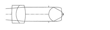
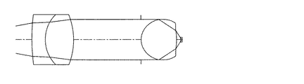
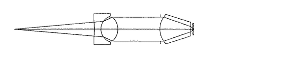
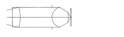
以下、本発明による実施の形態について図面を用いて説明する。図8は本発明の実施の形態を示す光ピックアップ装置の概略的な構成図である。 Embodiments of the present invention will be described below with reference to the drawings. FIG. 8 is a schematic configuration diagram of an optical pickup device showing an embodiment of the present invention.
図8の光ピックアップ装置は、対物レンズとして本発明による上述の両面非球面単玉対物レンズを使用したものであり、光源である半導体レーザ3と、光源3から射出される発散光の発散角を変換する力ップリングレンズ2と、カップリングレンズ2からの光束を光情報記録媒体の情報記録面5に集光する対物レンズ1と、光情報記録媒体の情報記録面5からの反射光を受光する光検出器4とを備えている。
The optical pickup apparatus of FIG. 8 uses the above-described double-sided aspherical single objective lens according to the present invention as an objective lens, and the semiconductor laser 3 as a light source and the divergence angle of the divergent light emitted from the light source 3 are set. The
図8の光ピックアップ装置は、更に、情報記録面5からの反射光を光検出器4に向けて分離するビームスプリッタ6と、力ップリングレンズ2と対物レンズ1との間に配置された1/4波長板7と、対物レンズ8に前置された絞り8と、シリンドリカルレンズ9と、フォーカス・トラッキング用の2軸アクチュエータ10とを備える。つまり、本実施形態において、集光光学系は、ビームスプリッタと、カップリングレンズと、1/4波長坂と、対物レンズと、絞りとを有するものである。なお、本実施形態においては、ビームスプリッタは、集光光学系に含まれないものと見なしてもよい。
The optical pickup device of FIG. 8 further includes a beam splitter 6 that separates reflected light from the information recording surface 5 toward the
また、対物レンズ1は、その外周に光軸に対し垂直方向に延びた面を持つフランジ部1aを有する。このフランジ部1aにより、対物レンズ1を光ピックアップ装置に精度よく取付ることができる。
The
そして、カップリングレンズ2は、入射された発散光束を光軸に対して、ほぼ平行光束にするコリメートレンズであっても良い。この場合は、コリメートレンズ2からの出射光束がほぼ平行光となるように、光源3もしくはコリメートレンズ2を、コリメートレンズの光軸方向に移動調整可能にすることが望ましい。
The
以上のように、本発明の光ピックアップ装置は、光源からの発散光束をほぼ平行光に変換するためのコリメートレンズと、該平行光を情報記録面に集光するための対物レンズとで構成しても良く、また、光源からの発散光束の角度を変えて発散光束又は収束光束に変換するための変換レンズであるカップリングレンズと、該カップリングレンズからの光束を情報記録面に集光するための対物レンズとで構成しても良い。また、光源からの発散光束を情報記録面に集光するための対物レンズ(有限共役型対物レンズ)のみで構成しても良い。 As described above, the optical pickup device of the present invention includes the collimating lens for converting the divergent light beam from the light source into substantially parallel light and the objective lens for condensing the parallel light on the information recording surface. In addition, a coupling lens which is a conversion lens for changing the angle of the divergent light beam from the light source to convert it into a divergent light beam or a convergent light beam, and the light beam from the coupling lens is condensed on the information recording surface. You may comprise with the objective lens for. Further, it may be configured only by an objective lens (finite conjugate objective lens) for condensing the divergent light beam from the light source on the information recording surface.
そして、このような光ピックアップ装置に本発明による非球面単玉対物レンズを使用することにより、光ディスク用の高密度記録再生が可能な光ピックアップ装置を得ることが出来る。 By using the aspherical single objective lens according to the present invention for such an optical pickup device, an optical pickup device capable of high-density recording / reproducing for an optical disk can be obtained.
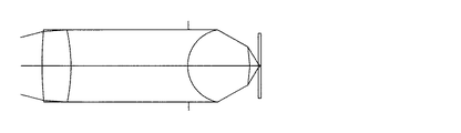
図57は、図8の光ピックアップ装置に、カップリングレンズ2を光軸方向に沿って変移させるための1軸アクチュエータ11を備えさせた光ピックアップ装置を示す図である。この変移装置としての1軸アクチュエータ11によって、カップリングレンズを光軸方向に適切な量だけ変移させて対物レンズ1に入射する光束の発散角を変えることにより、光学系で生じた球面収差の変動をキャンセルすることが出来る。また、光源の半導体レーザ3の発振波長が変動した場合、温度或いは湿度が変化した場合、光情報記録媒体の保護層の厚み誤差に起因して光学系で球面収差が発生する場合等に、1軸アクチュエータ11でカップリングレンズ2を光軸方向に適切な量だけ変移させて対物レンズ1に入射する光束の発散角を変えることにより、光学系で生じた球面収差の変動をキャンセルすることが出来る。
FIG. 57 is a diagram showing an optical pickup device in which the optical pickup device of FIG. 8 is provided with a uniaxial actuator 11 for shifting the
次に、本発明による対物レンズ及び光ピックアップ装置の実施例1〜15、28及びカップリングレンズとカップリングレンズ及び光ピックアップ装置の実施例16〜27、29〜32について説明する。なお、光ピックアップ装置の概略的な構成の例は、実施の形態で説明した図8、図57に示す通りであり、以下の各実施例に記述した構成や条件を満たすように、半導体レーザの基準波長の選択(光源の設定)、カップリングレンズの使用や削除あるいはカップリングレンズとしてコリメートレンズの使用といった設定、絞り8の開口の設定、また各部品の配置位置の設定等を行い、それに各実施例の対物レンズやカップリングレンズを搭載することにより本発明による光ピックアップ装置を得たものである。
Next, Examples 1 to 15 and 28 of the objective lens and optical pickup device according to the present invention and Examples 16 to 27 and 29 to 32 of the coupling lens, coupling lens, and optical pickup device will be described. An example of a schematic configuration of the optical pickup device is as shown in FIGS. 8 and 57 described in the embodiment, and the semiconductor laser is configured so as to satisfy the configurations and conditions described in the following examples. Select the reference wavelength (setting the light source), use or delete the coupling lens or use a collimating lens as the coupling lens, set the aperture of the
まず、対物レンズの実施例を説明する。以下の表1に実施例1〜15、28のデータの一覧を示す。 First, an example of the objective lens will be described. Table 1 below shows a list of data of Examples 1 to 15 and 28.

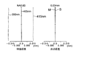
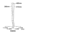
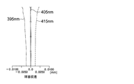
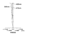
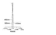
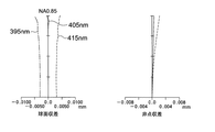
実施例1〜4及び6,7の対物レンズは、基準波長400nm用としての無限対物レンズであり、実施例8〜15の対物レンズは、基準波長405nm用としての無限対物レンズである。実施例6,9ではそれぞれ、対物レンズと光情報記録媒体の像面との間に、0.1mm厚の光情報記録媒体の保護層を想定するとともに、0.1mm以上のワーキングディスタンスとを設け、対物レンズにはプラスチック材料を使用している。実施例5の対物レンズは、基準波長660nm用としての有限対物レンズである。また、実施例15は、回折部を有する実施例である。なお、表1の、「波面収差」の「軸外」と記載されている部分の項が、像高特性を示している。表1から、実施例1〜15において、像高特性が良好であることがわかる。なお、レンズの材料は、実施例6,9,15がプラスチックであり、それら以外の実施例がガラスである。また、実施例5は透明基板なしで、それ以外の実施例の透明基板は0.1mmである。 The objective lenses of Examples 1 to 4 and 6 and 7 are infinite objective lenses for a reference wavelength of 400 nm, and the objective lenses of Examples 8 to 15 are infinite objective lenses for a reference wavelength of 405 nm. In Examples 6 and 9, a protective layer of 0.1 mm thick optical information recording medium is assumed between the objective lens and the image surface of the optical information recording medium, and a working distance of 0.1 mm or more is provided. The objective lens is made of plastic material. The objective lens of Example 5 is a finite objective lens for a reference wavelength of 660 nm. In addition, Example 15 is an example having a diffraction part. In Table 1, the term of “off-axis” of “wavefront aberration” indicates the image height characteristic. From Table 1, it can be seen that Examples 1 to 15 have good image height characteristics. In addition, as for the material of the lens, Examples 6, 9, and 15 are plastics, and other examples are glass. Further, Example 5 has no transparent substrate, and the transparent substrates of the other examples are 0.1 mm.
また、本実施例における非球面については、光軸方向をx軸、光軸に垂直な方向の高さをh、面の曲率半径をrとするとき次式(数1)で表す。但し、Kを円錐係数、A2iを非球面係数とする。 The aspherical surface in the present embodiment is expressed by the following equation (Equation 1) where the optical axis direction is the x axis, the height in the direction perpendicular to the optical axis is h, and the curvature radius of the surface is r. However, K is a conic coefficient and A2i is an aspheric coefficient.
〈実施例1〉
レンズデータを表2、非球面係数を表3に示す。実施例1のレンズを図1に示すが、図1(a)は断面図であり、図1(b)は収差図である。
<Example 1>
Table 2 shows lens data and Table 3 shows aspheric coefficients. The lens of Example 1 is shown in FIG. 1, in which FIG. 1 (a) is a sectional view and FIG. 1 (b) is an aberration diagram.
λ(波長)=400nm
f =1.765mm
NA=0.85
倍率=0
λ (wavelength) = 400 nm
f = 1.765 mm
NA = 0.85
Magnification = 0
〈実施例2〉
レンズデータを表4、非球面係数を表5に示す。実施例2のレンズを図2に示すが、図2(a)は断面図であり、図2(b)は収差図である。
<Example 2>
Table 4 shows lens data and Table 5 shows aspheric coefficients. The lens of Example 2 is shown in FIG. 2, in which FIG. 2 (a) is a sectional view and FIG. 2 (b) is an aberration diagram.
λ(波長)=400nm
f =1.765mm
NA=0.75
倍率=0
λ (wavelength) = 400 nm
f = 1.765 mm
NA = 0.75
Magnification = 0
〈実施例3〉
レンズデータを表6、非球面係数を表7に示す。実施例3のレンズを図3に示すが、図3(a)は断面図であり、図3(b)は収差図である。
<Example 3>
Table 6 shows lens data and Table 7 shows aspheric coefficients. The lens of Example 3 is shown in FIG. 3, where FIG. 3 (a) is a cross-sectional view and FIG. 3 (b) is an aberration diagram.
λ(波長)=400nm
f =1.765mm
NA=0.85
倍率=0
λ (wavelength) = 400 nm
f = 1.765 mm
NA = 0.85
Magnification = 0
〈実施例4〉
レンズデータを表8、非球面係数を表9に示す。実施例4のレンズを図4に示すが、図4(a)は断面図であり、図4(b)は収差図である。
<Example 4>
Table 8 shows lens data, and Table 9 shows aspheric coefficients. The lens of Example 4 is shown in FIG. 4. FIG. 4 (a) is a sectional view and FIG. 4 (b) is an aberration diagram.
λ(波長)=400nm
f =1.765mm
NA=0.75
倍率=0
λ (wavelength) = 400 nm
f = 1.765 mm
NA = 0.75
Magnification = 0
〈実施例5〉
レンズデータを表10、非球面係数を表11に示す。実施例5のレンズを図5に示すが、図5(a)は断面図であり、図5(b)は収差図である。
<Example 5>
Table 10 shows lens data and Table 11 shows aspheric coefficients. The lens of Example 5 is shown in FIG. 5. FIG. 5 (a) is a sectional view, and FIG. 5 (b) is an aberration diagram.
λ(波長)=660nm
f =0.131mm
NA=0.83
倍率=−0.1456
λ (wavelength) = 660 nm
f = 0.131mm
NA = 0.83
Magnification = -0.1456
〈実施例6〉
レンズデータを表12、非球面係数を表13に示す。実施例6のレンズを図6に示すが、図6(a)は断面図であり、図6(b)は収差図である。
<Example 6>
Table 12 shows lens data, and Table 13 shows aspheric coefficients. The lens of Example 6 is shown in FIG. 6. FIG. 6 (a) is a sectional view and FIG. 6 (b) is an aberration diagram.
λ(波長)=400nm
f =2.647mm
NA=0.85
倍率=0
λ (wavelength) = 400 nm
f = 2.647 mm
NA = 0.85
Magnification = 0
〈実施例7〉
レンズデータを表14、非球面係数を表15に示す。実施例7のレンズを図7に示すが、図7(a)は断面図であり、図7(b)は収差図である。
<Example 7>
Table 14 shows lens data and Table 15 shows aspheric coefficients. The lens of Example 7 is shown in FIG. 7, where FIG. 7 (a) is a cross-sectional view and FIG. 7 (b) is an aberration diagram.
λ(波長)=400nm
f =1.765mm
NA=0.85
倍率=0
λ (wavelength) = 400 nm
f = 1.765 mm
NA = 0.85
Magnification = 0
〈実施例8〉
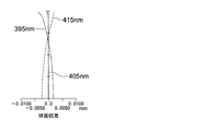
レンズデータ及び非球面係数を表16に示す。実施例8の対物レンズの断面図を図9に示し、収差図を図10に示す。また、第1面で1μm偏芯時の波面収差は0.021λであり、像高特性は0.011λ(内、コマ収差成分0.007λ)であった。
<Example 8>
Table 16 shows lens data and aspheric coefficients. A sectional view of the objective lens of Example 8 is shown in FIG. 9, and an aberration diagram is shown in FIG. The wavefront aberration when the first surface was decentered by 1 μm was 0.021λ, and the image height characteristic was 0.011λ (including coma aberration component 0.007λ).
〈実施例9〉
レンズデータ及び非球面係数を表17に示す。実施例9の対物レンズの断面図を図11に示し、収差図を図12に示す。
<Example 9>
Table 17 shows lens data and aspheric coefficients. A sectional view of the objective lens of Example 9 is shown in FIG. 11, and an aberration diagram is shown in FIG.
〈実施例10〉
レンズデータ及び非球面係数を表18に示す。実施例10の対物レンズの断面図を図13に示し、収差図を図14に示す。
<Example 10>
Table 18 shows lens data and aspheric coefficients. A sectional view of the objective lens of Example 10 is shown in FIG. 13, and aberration diagrams are shown in FIG.
〈実施例11〉
レンズデータ及び非球面係数を表19に示す。実施例11の対物レンズの断面図を図15に示し、収差図を図16に示す。
<Example 11>
Table 19 shows lens data and aspheric coefficients. A sectional view of the objective lens of Example 11 is shown in FIG. 15, and aberration diagrams are shown in FIG.
〈実施例12〉
レンズデータ及び非球面係数を表20に示す。実施例12の対物レンズの断面図を図17に示し、収差図を図18に示す。
<Example 12>
Table 20 shows lens data and aspheric coefficients. A sectional view of the objective lens of Example 12 is shown in FIG. 17, and aberration diagrams are shown in FIG.
〈実施例13〉
レンズデータ及び非球面係数を表21に示す。実施例13の対物レンズの断面図を図19に示し、収差図を図20に示す。
<Example 13>
Table 21 shows lens data and aspheric coefficients. A sectional view of the objective lens of Example 13 is shown in FIG. 19, and an aberration diagram is shown in FIG.
〈実施例14〉
レンズデータ及び非球面係数を表22に示す。実施例14の対物レンズの断面図を図21に示し、収差図を図22に示す。
<Example 14>
Table 22 shows lens data and aspheric coefficients. A sectional view of the objective lens of Example 14 is shown in FIG. 21, and aberration diagrams are shown in FIG.
〈実施例15〉
レンズデータ及び非球面係数を表23に示す。実施例15の対物レンズの断面図を図23に示し、収差図を図24に示す。
<Example 15>
Lens data and aspheric coefficients are shown in Table 23. A sectional view of the objective lens of Example 15 is shown in FIG. 23, and an aberration diagram is shown in FIG.
なお、回折面は、光路差関数Φbとして次式(数2)により表すことができる(後述する実施例26においても同様である)。ここで、hは光軸に垂直な方向の高さであり、bは光路差関数の係数である。 The diffractive surface can be expressed by the following equation (Equation 2) as an optical path difference function Φb (the same applies to Example 26 described later). Here, h is the height in the direction perpendicular to the optical axis, and b is a coefficient of the optical path difference function.
以上のように、実施例1〜15及び後述の実施例28によれば、光ピックアップ装置用の対物レンズにおいて開口数が大きく、像高特性の良い非球面単玉対物レンズを得ることが出来た。例えば、実施例1に見るように、波長400nmで開口数0.85であって、画角1°の像高に対し波面収差のrmsが0.07λ(λは波長)以下の単玉対物レンズを得ることが出来た。即ち、開口数が0.65以上と大きく、像高特性の良い、高密度記録再生装置に用いるのに好適な、光ピックアップ装置用の両面非球面単玉対物レンズを得ることが出来た。また、実施例1〜15、28において、偏心感度も良好にでき、球面収差、コマ収差も良好に補正可能である。また、実施例8及び28のように、像高特性及び第1面1μm偏芯時の波面収差は0.035λ以下であり、本発明による対物レンズは像高特性及び偏芯感度が良好に補正されている。 As described above, according to Examples 1 to 15 and Example 28 described later, an aspherical single objective lens having a large numerical aperture and good image height characteristics can be obtained in the objective lens for an optical pickup device. . For example, as shown in Example 1, a single lens objective lens having a wavelength of 400 nm, a numerical aperture of 0.85, and an rms of wavefront aberration of 0.07λ (λ is a wavelength) or less with respect to an image height of an angle of view of 1 °. I was able to get. That is, it was possible to obtain a double-sided aspherical single objective lens for an optical pickup device suitable for use in a high-density recording / reproducing apparatus having a large numerical aperture of 0.65 or more and good image height characteristics. In Examples 1 to 15 and 28, decentration sensitivity can be improved, and spherical aberration and coma can be corrected well. Further, as in Examples 8 and 28, the image height characteristic and the wavefront aberration when the first surface is decentered by 1 μm are 0.035λ or less, and the objective lens according to the present invention corrects the image height characteristic and decentration sensitivity well. Has been.
次に、カップリングレンズの実施例を説明する。以下の表24に実施例16〜27のデータの一覧を示す。 Next, examples of coupling lenses will be described. Table 24 below shows a list of data of Examples 16 to 27.
〈実施例16〉
レンズデータ及び非球面係数を表25に示す。実施例16の1群2枚構成のカップリングレンズと対物レンズの断面図を図25に示し、球面収差図を図26に示す。
<Example 16>
Lens data and aspheric coefficients are shown in Table 25. FIG. 25 shows a cross-sectional view of the coupling lens and objective lens having a two-group structure in Example 16 and FIG. 26 shows a spherical aberration diagram.
〈実施例17〉
レンズデータ及び非球面係数を表26に示す。実施例17の1群2枚構成のカップリングレンズと対物レンズの断面図を図27に示し、球面収差図を図28に示す。
<Example 17>
Lens data and aspheric coefficients are shown in Table 26. FIG. 27 shows a cross-sectional view of the coupling lens and objective lens of Example 17 having two lenses in one group, and FIG. 28 shows a spherical aberration diagram.
〈実施例18〉
レンズデータ及び非球面係数を表27に示す。実施例18の1群2枚構成のカップリングレンズと対物レンズの断面図を図29に示し、球面収差図を図30に示す。
<Example 18>
Table 27 shows lens data and aspheric coefficients. FIG. 29 shows a cross-sectional view of the coupling lens and objective lens having a two-group structure in Example 18 and FIG. 30 shows a spherical aberration diagram.
〈実施例19〉
レンズデータ及び非球面係数を表28に示す。実施例19の1群2枚構成のカップリングレンズと対物レンズの断面図を図31に示し、球面収差図を図32に示す。
<Example 19>
Lens data and aspheric coefficients are shown in Table 28. FIG. 31 shows a cross-sectional view of the coupling lens and objective lens having a two-group structure in Example 19 and FIG. 32 shows a spherical aberration diagram.
〈実施例20〉
レンズデータ及び非球面係数を表29に示す。実施例20の1群2枚構成のカップリングレンズと対物レンズの断面図を図33に示し、球面収差図を図34に示す。
<Example 20>
Lens data and aspheric coefficients are shown in Table 29. FIG. 33 shows a cross-sectional view of the coupling lens and objective lens having a two-group structure in Example 20, and FIG. 34 shows a spherical aberration diagram.
〈実施例21〉
レンズデータ及び非球面係数を表30に示す。実施例16の1群2枚構成のカップリングレンズと対物レンズの断面図を図35に示し、球面収差図を図36に示す。
<Example 21>
Table 30 shows lens data and aspheric coefficients. FIG. 35 shows a cross-sectional view of the coupling lens and objective lens of Example 16, which consists of two lenses in one group, and FIG. 36 shows a spherical aberration diagram.
〈実施例22〉
レンズデータ及び非球面係数を表31に示す。実施例22の1群2枚構成のカップリングレンズと対物レンズの断面図を図37に示し、球面収差図を図38に示す。
<Example 22>
Lens data and aspheric coefficients are shown in Table 31. FIG. 37 shows a cross-sectional view of the coupling lens and objective lens of Example 22, which has two elements in one group, and FIG. 38 shows a spherical aberration diagram.
〈実施例23〉
レンズデータ及び非球面係数を表32に示す。実施例23の1群2枚構成のカップリングレンズと対物レンズの断面図を図39に示し、球面収差図を図40に示す。
<Example 23>
Table 32 shows lens data and aspheric coefficients. FIG. 39 shows a cross-sectional view of the coupling lens and objective lens having a two-group structure in Example 23, and FIG. 40 shows a spherical aberration diagram.
〈実施例24〉
レンズデータ及び非球面係数を表33に示す。実施例24の1群2枚構成のカップリングレンズと対物レンズの断面図を図41に示し、球面収差図を図42に示す。
<Example 24>
Lens data and aspheric coefficients are shown in Table 33. FIG. 41 shows a cross-sectional view of the coupling lens and objective lens having a two-group structure in Example 24, and FIG. 42 shows a spherical aberration diagram.
〈実施例25〉
レンズデータ及び非球面係数を表34に示す。実施例25の1群2枚構成のカップリングレンズと対物レンズの断面図を図43に示し、球面収差図を図44に示す。
<Example 25>
Lens data and aspheric coefficients are shown in Table 34. FIG. 43 shows a cross-sectional view of the coupling lens and objective lens having a two-group structure in Example 25, and FIG. 44 shows a spherical aberration diagram.
〈実施例26〉
レンズデータ及び非球面係数を表35に示す。実施例26の1枚構成のカップリングレンズと対物レンズの断面図を図45に示し、球面収差図を図46に示す。
<Example 26>
Lens data and aspheric coefficients are shown in Table 35. FIG. 45 shows a cross-sectional view of the coupling lens and objective lens having a single structure according to Example 26, and FIG. 46 shows a spherical aberration diagram.
〈実施例27〉
レンズデータ及び非球面係数を表36に示す。実施例27の1群2枚構成のカップリングレンズと対物レンズの断面図を図47に示し、球面収差図を図48に示す。
<Example 27>
Lens data and aspheric coefficients are shown in Table 36. FIG. 47 shows a cross-sectional view of the coupling lens and objective lens having a two-group structure in Example 27, and FIG. 48 shows a spherical aberration diagram.
以上のように、本発明による対物レンズは屈折系の単玉対物レンズであるため、短波長側でアンダーな軸上色収差を生じるのであるが、実施例16〜27によれば、対物レンズとカップリングレンズとの合成系において、カップリングレンズによってこれを補正することができた。カップリングレンズの軸上色収差を短波長側でオーバーとして対物レンズの軸上色収差を軽減することができた。また、実施例16〜27において、像高特性も良好である。また、偏心感度も良好にでき、球面収差、コマ収差も良好に補正可能である。 As described above, since the objective lens according to the present invention is a refracting single lens objective lens, it causes under-axial chromatic aberration on the short wavelength side. However, according to Examples 16 to 27, the objective lens and the cup This was corrected by the coupling lens in the synthesis system with the ring lens. The axial chromatic aberration of the coupling lens can be reduced on the short wavelength side to reduce the axial chromatic aberration of the objective lens. In Examples 16 to 27, the image height characteristics are also good. In addition, decentration sensitivity can be improved, and spherical aberration and coma can be corrected well.
〈実施例28〉
レンズデータ及び非球面係数を表37に示す。実施例28の対物レンズの断面図を図49に示し、収差図を図50に示す。また、第1面で1μm偏芯時の波面収差は0.026λであり、像高特性は0.008λ(内、コマ収差成分0.003λ)であった。
<Example 28>
Lens data and aspheric coefficients are shown in Table 37. A sectional view of the objective lens of Example 28 is shown in FIG. 49, and an aberration diagram is shown in FIG. The wavefront aberration when the first surface was decentered by 1 μm was 0.026λ, and the image height characteristic was 0.008λ (including coma aberration component 0.003λ).
〈実施例29〉
レンズデータ及び非球面係数を表38に示す。実施例29の1枚構成のカップリングレンズと対物レンズの断面図を図51に示し、球面収差図を図52に示す。
<Example 29>
Table 38 shows lens data and aspheric coefficients. FIG. 51 shows a cross-sectional view of the single-coupled coupling lens and objective lens of Example 29, and FIG. 52 shows a spherical aberration diagram.
本実施例29では、対物レンズ及びカップリングレンズにプラスチック材料を用いることで、光学系の軽量化・フォーカシング機構或いはカップリングレンズ変移装置への負担の軽減を図っている。また、安価に大量生産することが出来る。更に、カップリングレンズを単玉の回折レンズとすることで、簡易な構成で良好に軸上色収差の補正された光学系を実現している。表39に様々な原因に起因して発生した球面収差を、カップリングレンズを変移させることで補正した結果を示す。この表39からわかるように、本実施例の光学系では、レーザの波長変動、温度変化、透明基板厚誤差に起因して発生した球面収差を良好に補正することが可能である。 In Example 29, a plastic material is used for the objective lens and the coupling lens, thereby reducing the weight on the optical system and the focusing mechanism or the burden on the coupling lens shifting device. Moreover, it can be mass-produced at low cost. Furthermore, by using a single diffractive lens as the coupling lens, an optical system in which the longitudinal chromatic aberration is well corrected with a simple configuration is realized. Table 39 shows the result of correcting the spherical aberration caused by various causes by shifting the coupling lens. As can be seen from Table 39, in the optical system of this example, it is possible to satisfactorily correct spherical aberration caused by laser wavelength fluctuation, temperature change, and transparent substrate thickness error.
〈実施例30〉
レンズデータ及び非球面係数を表40に示す。実施例30の1枚構成のカップリングレンズと対物レンズの断面図を図53に示し、球面収差図を図54に示す。
<Example 30>
Lens data and aspheric coefficients are shown in Table 40. FIG. 53 shows a cross-sectional view of the coupling lens and objective lens having a single structure according to Example 30, and FIG. 54 shows a spherical aberration diagram.
本実施例30では、対物レンズ及びカップリングレンズにプラスチック材料を用いることで、光学系の軽量化・フォーカシング機構或いはカップリングレンズ変移装置への負担の軽減を図っている。また、安価に大量生産することが出来る。光情報記録媒体に情報を記録する際、モードホップによる波面収差の劣化は許容できない問題となる。この光学系では、カップリングレンズを単玉の両面回折レンズとし、軸上色収差を補正過剰にすることで、基準波長の球面収差力ーブと短・長波長側の球面収差カーブを交差させている。その結果、波長シフトによる最適記録位置の変化が小さく抑えられ、モードホップ時の波面収差の劣化を防いでいる。表41に様々な原因に起因して発生した球面収差を、カップリングレンズを変移させることで補正した結果を示す。この表41からわかるように、本実施例の光学系では、レーザの波長変動、温度変化、透明基板厚誤差に起因して発生した球面収差を良好に補正することが可能である。 In Example 30, a plastic material is used for the objective lens and the coupling lens, thereby reducing the load on the optical system and the focusing mechanism or the coupling lens shifting device. Moreover, it can be mass-produced at low cost. When information is recorded on an optical information recording medium, degradation of wavefront aberration due to mode hops is an unacceptable problem. In this optical system, the coupling lens is a single-sided double-sided diffractive lens, and the axial chromatic aberration is overcorrected, so that the spherical aberration curve at the reference wavelength intersects the spherical aberration curve at the short and long wavelengths. Yes. As a result, the change in the optimum recording position due to the wavelength shift is suppressed to a small extent, and the wavefront aberration is prevented from deteriorating during mode hopping. Table 41 shows the result of correcting the spherical aberration caused by various causes by shifting the coupling lens. As can be seen from Table 41, in the optical system of this example, it is possible to satisfactorily correct spherical aberration caused by laser wavelength fluctuation, temperature change, and transparent substrate thickness error.
〈実施例31〉
レンズデータ及び非球面係数を表42に示す。実施例31の1群2枚構成のカップリングレンズと対物レンズの断面図を図55に示し、球面収差図を図56に示す。
<Example 31>
Lens data and aspheric coefficients are shown in Table 42. FIG. 55 shows a cross-sectional view of the coupling lens and objective lens having the structure of two elements per group in Example 31, and FIG. 56 shows a spherical aberration diagram.
本実施例31では、対物レンズにプラスチック材料を用いることで、光学系の軽量化・フォーカシング機構への負担の軽減を図っている。更に、カップリングレンズを1群2枚構成のダブレットレンズとすることで、良好に軸上色収差を補正している。また、光情報記録媒体側の面を非球面とすることで、非球面の収差補正効果によりカップリングレンズの開口数を大きく出来、全長が短いコンパクトな光学系を実現している。表43に様々な原因に起因して発生した球面収差を、カップリングレンズを変移させることで補正した結果を示す。この表43からわかるように、本実施例の光学系では、レーザの波長変動、温度変化、透明基板厚誤差に起因して発生した球面収差を良好に補正することが可能である。 In Example 31, a plastic material is used for the objective lens, thereby reducing the weight of the optical system and reducing the burden on the focusing mechanism. Furthermore, the axial chromatic aberration is corrected satisfactorily by making the coupling lens a doublet lens having two lenses per group. Further, by making the surface on the optical information recording medium side an aspherical surface, it is possible to increase the numerical aperture of the coupling lens due to the aspherical aberration correction effect, thereby realizing a compact optical system with a short overall length. Table 43 shows the result of correcting the spherical aberration caused by various causes by shifting the coupling lens. As can be seen from Table 43, in the optical system of this example, it is possible to satisfactorily correct spherical aberration caused by laser wavelength fluctuation, temperature change, and transparent substrate thickness error.
〈実施例32〉
単玉のカップリングレンズの片面にのみ、回折面を設けた実施例である。レンズデータ及び非球面係数を表44に示す。本実施例32の種々のパラメータを表24に示す。
<Example 32>
This is an example in which a diffractive surface is provided only on one side of a single coupling lens. Lens data and aspheric coefficients are shown in Table 44. Table 24 shows various parameters for the example 32.
本実施例32では、対物レンズ及びカップリングレンズにプラスチックを用いている。波長シフトによる最適記録位置の変化が小さく抑えられ、モードポップ時の波面収差の劣化を防止している。また、カップリングレンズの一方の面にのみ回折面を設けることで、カップリングレンズの面偏芯時の波面収差の劣化を防いでいる。さらに、カップリングレンズの光源側の面に回折面を設け、対物レンズの側の面に、光軸から離れるにしたがって屈折力の弱くなるような非球面を設けることで、カップリングレンズの偏芯及びトラッキングエラー時の波面収差の劣化を防いでいる。表45に様々な原因に起因して発生した球面収差をカップリングレンズを変移させることで補正した結果を示す。表45から、レーザ光の波長変動、温度変化、透明基板厚誤差に起因して発生した球面収差で良好に補正でき、また軸上色収差も良好に補正できることが分かる。 In Example 32, plastic is used for the objective lens and the coupling lens. The change in the optimum recording position due to the wavelength shift is kept small, and the deterioration of the wavefront aberration at the time of mode pop is prevented. Further, by providing a diffractive surface only on one surface of the coupling lens, the wavefront aberration is prevented from deteriorating when the surface of the coupling lens is decentered. Furthermore, by providing a diffractive surface on the light source side surface of the coupling lens, and providing an aspheric surface on the surface of the objective lens that has a refractive power that decreases with increasing distance from the optical axis, the coupling lens is decentered. In addition, deterioration of wavefront aberration at the time of tracking error is prevented. Table 45 shows the result of correcting the spherical aberration caused by various causes by shifting the coupling lens. From Table 45, it can be seen that it is possible to satisfactorily correct the spherical aberration caused by the wavelength variation of the laser light, temperature change, and transparent substrate thickness error, and it is also possible to satisfactorily correct the axial chromatic aberration.
本実施例32では,対物レンズ及びカップリングレンズにプラスチック材料を用いることで、光学系の軽量化、フォーカシング機構或いはカップリングレンズ変移装置への負担の軽減を図っている。また、安価に大量生産することが出来る。光情報記録媒体に情報を記録する際、モードホップによる波面収差の劣化は許容できない問題となる。この光学系では、カップリングレンズを単玉の回折レンズとし、軸上色収差を補正過剰にすることで基準波長の球面収差カーブと短・長波長側の球面収差カーブを交差させている。その結果、波長シフトによる最適記録位置の変化が小さく抑えられ、モードホップ時の波面収差の劣化を防いでいる。また、カップリングレンズの一方の面のみに回折面を設けることでカップリングレンズの面偏芯時の波面収差の劣化を防いでいる。更に,カップリングレンズの光源側の面に回折レンズを設け、対物レンズ側の面に光軸から離れるに従って屈折力の弱くなるような非球面を設けることで、カップリングレンズの偏芯及びトラッキングエラー時の波面収差の劣化を防いでいる。 In the thirty-second embodiment, by using a plastic material for the objective lens and the coupling lens, the weight of the optical system is reduced and the burden on the focusing mechanism or the coupling lens shift device is reduced. Moreover, it can be mass-produced at low cost. When information is recorded on an optical information recording medium, degradation of wavefront aberration due to mode hops is an unacceptable problem. In this optical system, the coupling lens is a single diffractive lens and the axial chromatic aberration is overcorrected so that the spherical aberration curve at the reference wavelength and the spherical aberration curve at the short / long wavelength side are crossed. As a result, the change in the optimum recording position due to the wavelength shift is suppressed to a small extent, and the wavefront aberration is prevented from deteriorating during mode hopping. Further, by providing a diffractive surface only on one surface of the coupling lens, deterioration of wavefront aberration at the time of decentering of the surface of the coupling lens is prevented. Furthermore, a diffractive lens is provided on the surface of the coupling lens on the light source side, and an aspheric surface whose refractive power decreases as the distance from the optical axis increases on the surface on the objective lens side. This prevents deterioration of the wavefront aberration at the time.
1 対物レンズ(両面非球面単玉対物レンズ)
1a フランジ部
2 カップリングレンズ
3 半導体レーザ(光源)
4 光検出器
5 情報記録面
11 1軸アクチュエータ(変移装置)
1 Objective lens (Double-sided aspherical single objective lens)
4 Photodetector 5 Information recording surface 11 Single-axis actuator (transition device)
Claims (152)
1.1≦d1/f≦3
但し、d1:軸上レンズ厚
f:焦点距離 An objective lens for recording / reproducing an optical information recording medium, wherein at least one surface is aspherical and satisfies the following expression.
1.1 ≦ d1 / f ≦ 3
Where d1: axial lens thickness f: focal length
f/νd≦0.060
但し、νd:アッベ数 The objective lens according to claim 1, wherein the objective lens satisfies the following expression.
f / νd ≦ 0.060
Where νd: Abbe number
1.40≦n
但し、n:使用波長での屈折率 The objective lens according to claim 1, wherein the objective lens satisfies the following expression.
1.40 ≦ n
Where n is the refractive index at the wavelength used.
1.40≦n<1.85 The objective lens according to claim 1, wherein the objective lens satisfies the following expression.
1.40 ≦ n <1.85
0.40≦r1/(n・f)≦0.70
但し、r1:光源側の近軸曲率半径 The objective lens according to claim 1, wherein the objective lens satisfies the following expression.
0.40 ≦ r1 / (n · f) ≦ 0.70
Where r1: paraxial radius of curvature on the light source side
f/νd≦0.060
但し、νd:アッベ数 The objective lens uses an optical information recording medium having a use wavelength of 500 nm or less and a protective layer thickness of 0.2 mm or less, having a numerical aperture of 0.7 or more and satisfying the following equation: The objective lens according to claim 1, 2 or 3.
f / νd ≦ 0.060
Where νd: Abbe number
0.40≦r1/(n・f)≦0.60
1.50≦n
但し、r1:光源側の面の近軸曲率半径
n:使用波長での屈折率 The objective lens uses an optical information recording medium having a use wavelength of 500 nm or less and a protective layer thickness of 0.2 mm or less, having a numerical aperture of 0.7 or more and satisfying the following equation: The objective lens according to claim 1, 2, 3, or 10.
0.40 ≦ r1 / (n · f) ≦ 0.60
1.50 ≦ n
Where r1: paraxial radius of curvature of light source side surface n: refractive index at wavelength used
前記対物レンズが少なくとも1面に非球面を有し、次式を満たすことを特徴とする光ピックアップ装置。
1.1≦d1/f≦3
但し、d1:軸上レンズ厚
f:焦点距離 A light source and an objective lens for condensing the light beam from the light source on the information recording surface of the optical information recording medium, and detecting light from the optical information recording medium to detect information on the optical information recording medium. In an optical pickup device that performs recording and / or reproduction,
The objective lens has at least one aspherical surface and satisfies the following expression.
1.1 ≦ d1 / f ≦ 3
Where d1: axial lens thickness f: focal length
f/νd≦0.060
但し、νd:アッベ数 The optical pickup device according to claim 14, wherein the objective lens satisfies the following expression.
f / νd ≦ 0.060
Where νd: Abbe number
1.40≦n
但し、n:使用波長での屈折率 The optical pickup device according to claim 14, wherein the objective lens satisfies the following expression.
1.40 ≦ n
Where n is the refractive index at the wavelength used.
1.40≦n<1.85 The optical pickup device according to claim 14, wherein the objective lens satisfies the following expression.
1.40 ≦ n <1.85
0.40≦r1/(n・f)≦0.70
但し、r1:光源側の近軸曲率半径 The optical pickup device according to any one of claims 114 to 21, wherein the objective lens satisfies the following expression.
0.40 ≦ r1 / (n · f) ≦ 0.70
Where r1: paraxial radius of curvature on the light source side
f/νd≦0.060
但し、νd:アッベ数 The objective lens uses an optical information recording medium having a use wavelength of 500 nm or less and a protective layer thickness of 0.2 mm or less, having a numerical aperture of 0.7 or more and satisfying the following equation: The optical pickup device according to claim 14, 15 or 16.
f / νd ≦ 0.060
Where νd: Abbe number
0.40≦r1/(n・f)≦0.60
1.50≦n
但し、r1:光源側の面の近軸曲率半径
n:使用波長での屈折率 The objective lens uses an optical information recording medium having a use wavelength of 500 nm or less and a protective layer thickness of 0.2 mm or less, having a numerical aperture of 0.7 or more and satisfying the following equation: 24. The optical pickup device according to claim 14, 15, 16, or 23.
0.40 ≦ r1 / (n · f) ≦ 0.60
1.50 ≦ n
Where r1: paraxial radius of curvature of light source side surface n: refractive index at wavelength used
1.1≦d1/f≦3
但し、d1:軸上レンズ厚
f:焦点距離 The objective lens according to claim 27, 28, 29, or 30, wherein:
1.1 ≦ d1 / f ≦ 3
Where d1: axial lens thickness f: focal length
f/νd≦0.060
但し、νd:アッベ数 32. The objective lens according to claim 27, wherein the following expression is satisfied.
f / νd ≦ 0.060
Where νd: Abbe number
1.40≦n
但し、n:使用波長での屈折率 The objective lens according to claim 27, wherein the objective lens satisfies the following expression.
1.40 ≦ n
Where n is the refractive index at the wavelength used.
1.40≦n<1.85 The objective lens according to claim 27, wherein the objective lens satisfies the following expression.
1.40 ≦ n <1.85
0.40≦r1/(n・f)≦0.70
但し、r1:光源側の近軸曲率半径 The objective lens according to claim 27, wherein the following expression is satisfied.
0.40 ≦ r1 / (n · f) ≦ 0.70
Where r1: paraxial radius of curvature on the light source side
前記光源の基準波長は500nm以下であり、前記対物レンズは、前記光源を使用した、保護層の厚みが0.2mm以下の光情報記録媒体の記録および/または再生に対して、開口数が0.65以上であり、少なくとも1面に非球面を有することを特徴とする光ピックアップ装置。 A light source and an objective lens for condensing the light beam from the light source on the information recording surface of the optical information recording medium, and detecting light from the optical information recording medium to detect information on the optical information recording medium. In an optical pickup device that performs recording and / or reproduction,
The reference wavelength of the light source is 500 nm or less, and the objective lens has a numerical aperture of 0 for recording and / or reproduction of an optical information recording medium using the light source and having a protective layer thickness of 0.2 mm or less. An optical pickup device having a height of 65 or more and an aspherical surface on at least one surface.
1.1≦d1/f≦3
但し、d1:軸上レンズ厚
f:焦点距離 40. The optical pickup device according to claim 36, 37, 38 or 39, wherein the objective lens satisfies the following expression.
1.1 ≦ d1 / f ≦ 3
Where d1: axial lens thickness f: focal length
f/νd≦0.060
但し、νd:アッベ数 41. The optical pickup device according to claim 36, wherein the objective lens satisfies the following expression.
f / νd ≦ 0.060
Where νd: Abbe number
1.40≦n
但し、n:使用波長での屈折率 The optical pickup device according to any one of claims 36 to 41, wherein the objective lens satisfies the following expression.
1.40 ≦ n
Where n is the refractive index at the wavelength used.
1.40≦n<1.85 The optical pickup device according to any one of claims 36 to 41, wherein the objective lens satisfies the following expression.
1.40 ≦ n <1.85
0.40≦r1/(n・f)≦0.70
但し、r1:光源側の近軸曲率半径
1.1≦d1/f≦3
但し、d1:軸上レンズ厚
f:焦点距離 44. The optical pickup device according to claim 36, wherein the objective lens satisfies the following expression.
0.40 ≦ r1 / (n · f) ≦ 0.70
However, r1: Paraxial radius of curvature on the light source side 1.1 ≦ d1 / f ≦ 3
Where d1: axial lens thickness f: focal length
1.1≦d1/f≦3
但し、d1:軸上レンズ厚
f:焦点距離 48. The objective lens according to claim 45, 46 or 47, wherein:
1.1 ≦ d1 / f ≦ 3
Where d1: axial lens thickness f: focal length
f/νd≦0.060
但し、νd:アッベ数 49. The objective lens according to claim 45, 46, 47 or 48, wherein the following expression is satisfied.
f / νd ≦ 0.060
Where νd: Abbe number
1.40≦n
但し、n:使用波長での屈折率 The objective lens according to claim 45, wherein the objective lens satisfies the following expression.
1.40 ≦ n
Where n is the refractive index at the wavelength used.
1.40≦n<1.85 The objective lens according to claim 45, wherein the objective lens satisfies the following expression.
1.40 ≦ n <1.85
0.40≦r1/(n・f)≦0.70
但し、r1:光源側の近軸曲率半径 52. The objective lens according to claim 45, wherein the following expression is satisfied.
0.40 ≦ r1 / (n · f) ≦ 0.70
Where r1: paraxial radius of curvature on the light source side
前記対物レンズは、少なくとも1面に非球面を有し、開口数が0.75以上であり、プラスチック材料からなることを特徴とする光ピックアップ装置。 A light source and an objective lens for condensing the light beam from the light source on the information recording surface of the optical information recording medium, and detecting light from the optical information recording medium to detect information on the optical information recording medium. In an optical pickup device that performs recording and / or reproduction,
The objective lens has an aspherical surface on at least one surface, has a numerical aperture of 0.75 or more, and is made of a plastic material.
1.1≦d1/f≦3
但し、d1:軸上レンズ厚
f:焦点距離 The optical pickup device according to claim 53, 54, or 55, wherein the objective lens satisfies the following expression.
1.1 ≦ d1 / f ≦ 3
Where d1: axial lens thickness f: focal length
f/νd≦0.060
但し、νd:アッベ数 57. The optical pickup device according to claim 53, 54, 55, or 56, wherein the objective lens satisfies the following expression.
f / νd ≦ 0.060
Where νd: Abbe number
1.40≦n
但し、n:使用波長での屈折率 The optical pickup device according to any one of claims 53 to 57, wherein the objective lens satisfies the following expression.
1.40 ≦ n
Where n is the refractive index at the wavelength used.
1.40≦n<1.85 The optical pickup device according to any one of claims 53 to 57, wherein the objective lens satisfies the following expression.
1.40 ≦ n <1.85
0.40≦r1/(n・f)≦0.70
但し、r1:光源側の近軸曲率半径 The optical pickup device according to any one of claims 53 to 59, wherein the objective lens satisfies the following expression.
0.40 ≦ r1 / (n · f) ≦ 0.70
Where r1: paraxial radius of curvature on the light source side
n≧1.85
但し、n:使用波長での屈折率 An objective lens for recording / reproduction of an optical information recording medium, wherein at least one surface is aspherical, the numerical aperture is 0.65 or more, and satisfies the following expression.
n ≧ 1.85
Where n is the refractive index at the wavelength used.
1.1≦d1/f≦3
但し、d1:軸上レンズ厚
f:焦点距離 65. The objective lens according to claim 61, 62, 63 or 64, wherein the following expression is satisfied.
1.1 ≦ d1 / f ≦ 3
Where d1: axial lens thickness f: focal length
0.40≦r1/(n・f)≦0.70
但し、r1:光源側の近軸曲率半径 The objective lens according to any one of claims 61 to 65, wherein:
0.40 ≦ r1 / (n · f) ≦ 0.70
Where r1: paraxial radius of curvature on the light source side
前記対物レンズは、少なくとも1面に非球面を有し、開口数が0.65以上であり、次式を満足することを特徴とする光ピックアップ装置。
n≧1.85
但し、n:使用波長での屈折率 A light source and an objective lens for condensing the light beam from the light source on the information recording surface of the optical information recording medium, and detecting light from the optical information recording medium to detect information on the optical information recording medium. In an optical pickup device that performs recording and / or reproduction,
The objective lens has an aspherical surface on at least one surface, has a numerical aperture of 0.65 or more, and satisfies the following expression.
n ≧ 1.85
Where n is the refractive index at the wavelength used.
1.1≦d1/f≦3
但し、d1:軸上レンズ厚
f:焦点距離 The optical pickup device according to claim 67, 68, 69 or 70, wherein the objective lens satisfies the following expression.
1.1 ≦ d1 / f ≦ 3
Where d1: axial lens thickness f: focal length
0.40≦r1/(n・f)≦0.70
但し、r1:光源側の近軸曲率半径 The optical pickup device according to any one of claims 67 to 71, wherein the objective lens satisfies the following expression.
0.40 ≦ r1 / (n · f) ≦ 0.70
Where r1: paraxial radius of curvature on the light source side
1.40≦n<1.85
但し、n:使用波長での屈折率 An objective lens for recording / reproduction of an optical information recording medium, wherein at least one surface is aspherical, the numerical aperture is 0.65 or more, and satisfies the following expression.
1.40 ≦ n <1.85
Where n is the refractive index at the wavelength used.
前記対物レンズは、少なくとも1面に非球面を有し、開口数が0.65以上であり、次式を満足することを特徴とする光ピックアップ装置。
1.40≦n<1.85
但し、n:使用波長での屈折率 A light source and an objective lens for condensing the light beam from the light source on the information recording surface of the optical information recording medium, and detecting light from the optical information recording medium to detect information on the optical information recording medium. In an optical pickup device that performs recording and / or reproduction,
The objective lens has an aspherical surface on at least one surface, has a numerical aperture of 0.65 or more, and satisfies the following expression.
1.40 ≦ n <1.85
Where n is the refractive index at the wavelength used.
1.1≦d1/f≦3
但し、d1:軸上レンズ厚
f:焦点距離 An objective lens for recording / reproducing an optical information recording medium, wherein at least one surface is aspherical, has at least one diffractive surface, and satisfies the following expression.
1.1 ≦ d1 / f ≦ 3
Where d1: axial lens thickness f: focal length
前記対物レンズは、少なくとも1面に非球面を有し、少なくとも一方のレンズ面に回折面を有し、次式を満たすことを特徴とする光ピックアップ装置。
1.1≦d1/f≦3
但し、d1:軸上レンズ厚
f:焦点距離 A light source and an objective lens for condensing the light beam from the light source on the information recording surface of the optical information recording medium, and detecting light from the optical information recording medium to detect information on the optical information recording medium. In an optical pickup device that performs recording and / or reproduction,
The objective lens has an aspherical surface on at least one surface, a diffractive surface on at least one lens surface, and satisfies the following expression.
1.1 ≦ d1 / f ≦ 3
Where d1: axial lens thickness f: focal length
前記カップリングレンズは前記対物レンズの色収差を補正する機能を有し、
前記対物レンズは、少なくとも1面に非球面を有し、次式を満たすことを特徴とする光ピックアップ装置。
1.1≦d1/f≦3
但し、d1:軸上レンズ厚
f:焦点距離 A light source, a coupling lens for changing a divergence angle of diverging light emitted from the light source, and an objective lens for condensing a light beam through the coupling lens on an information recording surface of an optical information recording medium, In an optical pickup device for recording and / or reproducing information on the optical information recording medium by detecting light from the optical information recording medium,
The coupling lens has a function of correcting chromatic aberration of the objective lens;
The objective lens has an aspherical surface on at least one surface, and satisfies the following formula.
1.1 ≦ d1 / f ≦ 3
Where d1: axial lens thickness f: focal length
f/νd≦0.060
但し、νd:アッベ数 The optical pickup device according to any one of claims 97 to 101, wherein the objective lens satisfies the following expression.
f / νd ≦ 0.060
Where νd: Abbe number
1.40≦n
但し、n:使用波長での屈折率 The optical pickup device according to any one of claims 97 to 102, wherein the objective lens satisfies the following expression.
1.40 ≦ n
Where n is the refractive index at the wavelength used.
1.40≦n<1.85 The optical pickup device according to any one of claims 97 to 102, wherein the objective lens satisfies the following expression.
1.40 ≦ n <1.85
0.40≦r1/(n・f)≦0.70
但し、r1:光源側の近軸曲率半径 The optical pickup device according to any one of claims 97 to 104, wherein the objective lens satisfies the following expression.
0.40 ≦ r1 / (n · f) ≦ 0.70
Where r1: paraxial radius of curvature on the light source side
f/νd≦0.060
但し、νd:アッベ数 The objective lens uses an optical information recording medium having a use wavelength of 500 nm or less and a protective layer thickness of 0.2 mm or less, having a numerical aperture of 0.7 or more and satisfying the following equation: The optical pickup device according to claim 97, 98 or 99.
f / νd ≦ 0.060
Where νd: Abbe number
0.40≦r1/(n・f)≦0.60
1.50≦n
但し、r1:光源側の面の近軸曲率半径
n:使用波長での屈折率 The objective lens uses an optical information recording medium having a use wavelength of 500 nm or less and a protective layer thickness of 0.2 mm or less, having a numerical aperture of 0.7 or more and satisfying the following equation: The optical pickup device according to claim 97, 98, 99 or 106.
0.40 ≦ r1 / (n · f) ≦ 0.60
1.50 ≦ n
Where r1: paraxial radius of curvature of light source side surface n: refractive index at wavelength used
前記カップリングレンズは前記対物レンズの色収差を補正する機能を有し、
前記光源の基準波長は500nm以下であり、前記対物レンズは、前記光源を使用した、保護層の厚みが0.2mm以下の光情報記録媒体の記録および/または再生に対して、開口数が0.65以上であり、少なくとも1面に非球面を有することを特徴とする光ピックアップ装置。 A light source, a coupling lens for changing a divergence angle of diverging light emitted from the light source, and an objective lens for condensing a light beam through the coupling lens on an information recording surface of an optical information recording medium, In an optical pickup device for recording and / or reproducing information with respect to the optical information recording medium by detecting light from the optical information recording medium,
The coupling lens has a function of correcting chromatic aberration of the objective lens;
The reference wavelength of the light source is 500 nm or less, and the objective lens has a numerical aperture of 0 for recording and / or reproduction of an optical information recording medium using the light source and having a protective layer thickness of 0.2 mm or less. An optical pickup device having a height of 65 or more and an aspherical surface on at least one surface.
1.1≦d1/f≦3
但し、d1:軸上レンズ厚
f:焦点距離 114. The optical pickup device according to claim 110, 111, 112, or 113, wherein the objective lens satisfies the following formula.
1.1 ≦ d1 / f ≦ 3
Where d1: axial lens thickness f: focal length
f/νd≦0.060
但し、νd:アッベ数 The optical pickup device according to any one of claims 110 to 114, wherein the objective lens satisfies the following expression.
f / νd ≦ 0.060
Where νd: Abbe number
1.40≦n
但し、n:使用波長での屈折率 116. The optical pickup device according to claim 110, wherein the objective lens satisfies the following expression.
1.40 ≦ n
Where n is the refractive index at the wavelength used.
1.40≦n<1.85 116. The optical pickup device according to claim 110, wherein the objective lens satisfies the following expression.
1.40 ≦ n <1.85
0.40≦r1/(n・f)≦0.70
但し、r1:光源側の近軸曲率半径
1.1≦d1/f≦3
但し、d1:軸上レンズ厚 118. The optical pickup device according to any one of claims 110 to 117, wherein the objective lens satisfies the following expression.
0.40 ≦ r1 / (n · f) ≦ 0.70
However, r1: Paraxial radius of curvature on the light source side 1.1 ≦ d1 / f ≦ 3
Where d1: axial lens thickness
前記カップリングレンズは前記対物レンズの色収差を補正する機能を有し、
前記対物レンズは、少なくとも1面に非球面を有し、開口数が0.75以上であり、プラスチック材料からなることを特徴とする光ピックアップ装置。 A light source, a coupling lens for changing a divergence angle of diverging light emitted from the light source, and an objective lens for condensing a light beam through the coupling lens on an information recording surface of an optical information recording medium, In an optical pickup device for recording and / or reproducing information with respect to the optical information recording medium by detecting light from the optical information recording medium,
The coupling lens has a function of correcting chromatic aberration of the objective lens;
The objective lens has an aspherical surface on at least one surface, has a numerical aperture of 0.75 or more, and is made of a plastic material.
1.1≦d1/f≦3
但し、d1:軸上レンズ厚
f:焦点距離 122. The optical pickup device according to claim 119, 120 or 121, wherein the objective lens satisfies the following expression.
1.1 ≦ d1 / f ≦ 3
Where d1: axial lens thickness f: focal length
f/νd≦0.060
但し、νd:アッベ数 The optical pickup device according to claim 119, 120, 121, or 122, wherein the objective lens satisfies the following expression.
f / νd ≦ 0.060
Where νd: Abbe number
1.40≦n
但し、n:使用波長での屈折率 The optical pickup device according to any one of claims 119 to 123, wherein the objective lens satisfies the following expression.
1.40 ≦ n
Where n is the refractive index at the wavelength used.
1.40≦n<1.85 The optical pickup device according to any one of claims 119 to 123, wherein the objective lens satisfies the following expression.
1.40 ≦ n <1.85
0.40≦r1/(n・f)≦0.70
但し、r1:光源側の近軸曲率半径 The optical pickup device according to any one of claims 119 to 125, wherein the objective lens satisfies the following expression.
0.40 ≦ r1 / (n · f) ≦ 0.70
Where r1: paraxial radius of curvature on the light source side
前記カップリングレンズは前記対物レンズの色収差を補正する機能を有し、
前記対物レンズは、少なくとも1面に非球面を有し、開口数が0.65以上であり、次式を満足することを特徴とする光ピックアップ装置。
n≧1.85
但し、n:使用波長での屈折率 A light source, a coupling lens for changing a divergence angle of diverging light emitted from the light source, and an objective lens for condensing a light beam through the coupling lens on an information recording surface of an optical information recording medium, In an optical pickup device for recording and / or reproducing information with respect to the optical information recording medium by detecting light from the optical information recording medium,
The coupling lens has a function of correcting chromatic aberration of the objective lens;
The objective lens has an aspherical surface on at least one surface, has a numerical aperture of 0.65 or more, and satisfies the following expression.
n ≧ 1.85
Where n is the refractive index at the wavelength used.
1.1≦d1/f≦3
但し、d1:軸上レンズ厚
f:焦点距離 131. The optical pickup device according to claim 127, 128, 129 or 130, wherein the objective lens satisfies the following formula.
1.1 ≦ d1 / f ≦ 3
Where d1: axial lens thickness f: focal length
0.40≦r1/(n・f)≦0.70
但し、r1:光源側の近軸曲率半径 The optical pickup device according to any one of claims 127 to 131, wherein the objective lens satisfies the following expression.
0.40 ≦ r1 / (n · f) ≦ 0.70
Where r1: paraxial radius of curvature on the light source side
前記カップリングレンズは前記対物レンズの色収差を補正する機能を有し、
前記対物レンズは、少なくとも1面に非球面を有し、開口数が0.65以上であり、次式を満足することを特徴とする光ピックアップ装置。
1.40≦n<1.85
但し、n:使用波長での屈折率 A light source, a coupling lens for changing a divergence angle of diverging light emitted from the light source, and an objective lens for condensing a light beam through the coupling lens on an information recording surface of an optical information recording medium, In an optical pickup device for recording and / or reproducing information with respect to the optical information recording medium by detecting light from the optical information recording medium,
The coupling lens has a function of correcting chromatic aberration of the objective lens;
The objective lens has an aspherical surface on at least one surface, has a numerical aperture of 0.65 or more, and satisfies the following expression.
1.40 ≦ n <1.85
Where n is the refractive index at the wavelength used.
δfb・NA2≦0.25μm (δfb>0)
但し、δfb:波長が基準波長から+1nm変化した時の、合成系の焦点位置
の変化(μm)
NA:対物レンズの光情報記録媒体側の開口数 The optical pickup device according to any one of claims 97 to 137, wherein a chromatic aberration of a combination system of the objective lens and the coupling lens satisfies the following expression.
δfb · NA2 ≦ 0.25 μm (δfb> 0)
However, δfb: the focal position of the synthesis system when the wavelength changes +1 nm from the reference wavelength
Change (μm)
NA: Numerical aperture of the objective lens on the optical information recording medium side
0.02μm≦δfb・NA2≦0.15μm (δfb>0) 141. The optical pickup device according to claim 138, wherein the following expression is satisfied.
0.02 μm ≦ δfb · NA2 ≦ 0.15 μm (δfb> 0)
0.1≦|m|≦0.5 (m<0)
但し、m:対物レンズとカップリングレンズとの合成系の倍率 140. The optical pickup device according to any one of claims 97 to 139, wherein:
0.1 ≦ | m | ≦ 0.5 (m <0)
Where m: magnification of the composite system of the objective lens and the coupling lens
Priority Applications (1)
| Application Number | Priority Date | Filing Date | Title |
|---|---|---|---|
| JP2007166230A JP4305549B2 (en) | 1999-09-01 | 2007-06-25 | Objective lens and optical pickup device |
Applications Claiming Priority (3)
| Application Number | Priority Date | Filing Date | Title |
|---|---|---|---|
| JP24729499 | 1999-09-01 | ||
| JP2000060843 | 2000-03-06 | ||
| JP2007166230A JP4305549B2 (en) | 1999-09-01 | 2007-06-25 | Objective lens and optical pickup device |
Related Parent Applications (1)
| Application Number | Title | Priority Date | Filing Date |
|---|---|---|---|
| JP2000262372A Division JP4254986B2 (en) | 1999-09-01 | 2000-08-31 | Objective lens and optical pickup device |
Related Child Applications (2)
| Application Number | Title | Priority Date | Filing Date |
|---|---|---|---|
| JP2008189791A Division JP4232857B2 (en) | 1999-09-01 | 2008-07-23 | Optical pickup device and optical information recording medium recording / reproducing device |
| JP2009057844A Division JP4973677B2 (en) | 1999-09-01 | 2009-03-11 | Objective lens and optical pickup device |
Publications (2)
| Publication Number | Publication Date |
|---|---|
| JP2007294103A true JP2007294103A (en) | 2007-11-08 |
| JP4305549B2 JP4305549B2 (en) | 2009-07-29 |
Family
ID=26538196
Family Applications (6)
| Application Number | Title | Priority Date | Filing Date |
|---|---|---|---|
| JP2000262372A Expired - Lifetime JP4254986B2 (en) | 1999-09-01 | 2000-08-31 | Objective lens and optical pickup device |
| JP2007166230A Expired - Lifetime JP4305549B2 (en) | 1999-09-01 | 2007-06-25 | Objective lens and optical pickup device |
| JP2008189791A Expired - Lifetime JP4232857B2 (en) | 1999-09-01 | 2008-07-23 | Optical pickup device and optical information recording medium recording / reproducing device |
| JP2009057844A Expired - Lifetime JP4973677B2 (en) | 1999-09-01 | 2009-03-11 | Objective lens and optical pickup device |
| JP2011278235A Expired - Fee Related JP5126407B2 (en) | 1999-09-01 | 2011-12-20 | Optical pickup apparatus and optical information recording medium recording and / or reproducing apparatus |
| JP2012193498A Pending JP2012234621A (en) | 1999-09-01 | 2012-09-03 | Optical pickup device |
Family Applications Before (1)
| Application Number | Title | Priority Date | Filing Date |
|---|---|---|---|
| JP2000262372A Expired - Lifetime JP4254986B2 (en) | 1999-09-01 | 2000-08-31 | Objective lens and optical pickup device |
Family Applications After (4)
| Application Number | Title | Priority Date | Filing Date |
|---|---|---|---|
| JP2008189791A Expired - Lifetime JP4232857B2 (en) | 1999-09-01 | 2008-07-23 | Optical pickup device and optical information recording medium recording / reproducing device |
| JP2009057844A Expired - Lifetime JP4973677B2 (en) | 1999-09-01 | 2009-03-11 | Objective lens and optical pickup device |
| JP2011278235A Expired - Fee Related JP5126407B2 (en) | 1999-09-01 | 2011-12-20 | Optical pickup apparatus and optical information recording medium recording and / or reproducing apparatus |
| JP2012193498A Pending JP2012234621A (en) | 1999-09-01 | 2012-09-03 | Optical pickup device |
Country Status (8)
| Country | Link |
|---|---|
| US (2) | US6411442B1 (en) |
| EP (2) | EP1986189B1 (en) |
| JP (6) | JP4254986B2 (en) |
| KR (2) | KR100759650B1 (en) |
| CN (3) | CN101211602A (en) |
| AT (2) | ATE469418T1 (en) |
| DE (2) | DE60044473D1 (en) |
| TW (1) | TW504582B (en) |
Cited By (2)
| Publication number | Priority date | Publication date | Assignee | Title |
|---|---|---|---|---|
| JP2011524020A (en) * | 2008-05-16 | 2011-08-25 | デイ アンド ナイト ディスプレイ システムズ エルエルシー | Night vision glasses |
| US8121012B2 (en) | 2008-11-19 | 2012-02-21 | Hoya Corporation | Objective lens and optical information recording/reproducing apparatus |
Families Citing this family (87)
| Publication number | Priority date | Publication date | Assignee | Title |
|---|---|---|---|---|
| CN1172299C (en) * | 1999-10-30 | 2004-10-20 | 三星电子株式会社 | Optical probe |
| EP2264707A3 (en) * | 2000-05-12 | 2012-03-07 | Konica Minolta Opto, Inc. | Optical pick-up apparatus |
| JP4076047B2 (en) * | 2000-08-11 | 2008-04-16 | フジノン株式会社 | Objective lens for optical recording medium and optical pickup device using the same |
| KR100765736B1 (en) * | 2000-09-21 | 2007-10-15 | 삼성전자주식회사 | Optical pickup apparatus by employing chromatic aberration compensating lens |
| WO2002037484A2 (en) * | 2000-10-30 | 2002-05-10 | Konica Corporation | Objective lens, light converging optical system, optical pickup apparatus, and recording/reproducing apparatus |
| KR100506565B1 (en) * | 2000-11-16 | 2005-08-10 | 닛뽕빅터 가부시키가이샤 | Objective lens for an optical disk |
| US7133331B2 (en) * | 2000-12-28 | 2006-11-07 | Victor Company Of Japan, Limited | Recording medium having a substrate containing microscopic pattern of parallel groove and land sections and recording/reproducing equipment therefor |
| JP3712628B2 (en) * | 2001-04-06 | 2005-11-02 | シャープ株式会社 | Objective lens, method for correcting manufacturing error thereof, and optical pickup device using the objective lens |
| JP4814476B2 (en) | 2001-04-20 | 2011-11-16 | Tdk株式会社 | Reproduction method of optical information medium |
| CN1302476C (en) * | 2001-04-25 | 2007-02-28 | 皇家菲利浦电子有限公司 | Scanning device including plastic high-numerical aperture objective |
| US7239459B2 (en) * | 2001-04-25 | 2007-07-03 | Koninklijke Philips Electronics N.V. | Scanning device including plastic high-numerical aperture objective |
| JP4817035B2 (en) * | 2001-05-09 | 2011-11-16 | コニカミノルタホールディングス株式会社 | Objective lens, optical pickup device, and recording / reproducing device |
| JP4817036B2 (en) * | 2001-06-20 | 2011-11-16 | コニカミノルタホールディングス株式会社 | Objective lens, optical pickup device and recording / reproducing device |
| WO2003001270A1 (en) * | 2001-06-25 | 2003-01-03 | Sony Corporation | Objective for optical pickup and optical pickup using the objective |
| JP2003043349A (en) * | 2001-08-03 | 2003-02-13 | Konica Corp | Optical pickup lens |
| JP2003085806A (en) * | 2001-09-07 | 2003-03-20 | Pentax Corp | Objective lens for optical head and optical head using the same |
| JP4494686B2 (en) * | 2001-09-18 | 2010-06-30 | Hoya株式会社 | Objective lens for optical head and optical head using the same |
| US6636366B1 (en) * | 2001-09-21 | 2003-10-21 | Victor Company Of Japan, Limited | Objective for optical disk, optical pickup, optical disk writer-reader, and optical disk reader |
| JP4130938B2 (en) * | 2001-09-28 | 2008-08-13 | Hoya株式会社 | Objective optical system for optical pickup |
| US7274646B2 (en) | 2001-10-04 | 2007-09-25 | Ricoh Company, Ltd. | Object lens for an infinite-type optical pickup, optical pickup and optical information processing device |
| TWI239520B (en) * | 2001-10-12 | 2005-09-11 | Konica Corp | Objective lens, optical element, optical pick-up apparatus and optical information recording and/or reproducing apparatus equipped therewith |
| JP3804826B2 (en) * | 2001-11-15 | 2006-08-02 | コニカミノルタホールディングス株式会社 | Objective lens for optical pickup device and optical pickup device |
| EP1459108B1 (en) * | 2001-12-21 | 2005-11-23 | Koninklijke Philips Electronics N.V. | Objective lens for scanning optical disks (dvds) |
| US6594086B1 (en) * | 2002-01-16 | 2003-07-15 | Optonics, Inc. (A Credence Company) | Bi-convex solid immersion lens |
| JP2003287675A (en) | 2002-01-22 | 2003-10-10 | Konica Corp | Light convergence optical system, optical pickup device, recording and reproducing device, aberration correcting element, and objective |
| CN100456371C (en) * | 2002-04-26 | 2009-01-28 | 柯尼卡美能达精密光学株式会社 | Recording reproducing optical system, objective lens, and aberration correcting optical element |
| JP2004005943A (en) | 2002-04-26 | 2004-01-08 | Konica Minolta Holdings Inc | Registration reproduction optics, objective lens, optical element for aberation compensation, optical pickup system, and orecording/reproducing apparatus, aberration correcting optical element, optical pickup device and recording and reproducing device |
| JP2003337281A (en) * | 2002-05-17 | 2003-11-28 | Minolta Co Ltd | Objective lens for optical pickup |
| KR20040003908A (en) * | 2002-07-04 | 2004-01-13 | 엘지전자 주식회사 | Optical Pick-Up using slim-type lens |
| JP2004327003A (en) | 2002-07-26 | 2004-11-18 | Sharp Corp | Optical pickup |
| JP2005535067A (en) * | 2002-08-05 | 2005-11-17 | コーニンクレッカ フィリップス エレクトロニクス エヌ ヴィ | Scanning apparatus including an objective lens system formed of a single material |
| CN100373480C (en) * | 2002-08-05 | 2008-03-05 | 皇家飞利浦电子股份有限公司 | Scanning device including an objective system with a lens protection device |
| CN100585705C (en) * | 2002-08-28 | 2010-01-27 | 柯尼卡美能达控股株式会社 | Object lens for optical pickup device, optical pickup device and optical information recording/reproducing device |
| JP2007316655A (en) * | 2002-08-28 | 2007-12-06 | Konica Minolta Holdings Inc | Object lens for optical pickup device, optical pickup device and optical information recording/reproducing device |
| JP2004252135A (en) | 2002-08-28 | 2004-09-09 | Konica Minolta Holdings Inc | Objective for optical pickup device, optical pickup device and optical information recording and reproducing device |
| JP4305722B2 (en) | 2002-09-05 | 2009-07-29 | コニカミノルタホールディングス株式会社 | Manufacturing method of molded lens |
| JP4513946B2 (en) * | 2002-10-31 | 2010-07-28 | コニカミノルタホールディングス株式会社 | Optical system for optical pickup device, optical pickup device, and optical information recording / reproducing device |
| US7443778B2 (en) * | 2003-02-27 | 2008-10-28 | Matsushita Electric Industrial Co., Ltd. | Optical head device and optical information device using the same, computer, optical disk player, car navigation system, optical disk recorder, and optical disk server |
| JP4119780B2 (en) * | 2003-03-28 | 2008-07-16 | Hoya株式会社 | Method for manufacturing molded body, manufacturing apparatus, and objective lens for optical pickup |
| US7212485B2 (en) | 2003-04-14 | 2007-05-01 | Hoya Corporation | Objective lens and method for manufacture thereof |
| EP1469465A3 (en) * | 2003-04-15 | 2009-03-25 | Konica Minolta Opto, Inc. | Optical pickup device optical information recording and reproducing apparatus and objective lens |
| JP4341416B2 (en) * | 2004-01-30 | 2009-10-07 | コニカミノルタオプト株式会社 | Diffractive optical element and optical pickup device |
| JPWO2005101393A1 (en) * | 2004-04-13 | 2008-03-06 | コニカミノルタオプト株式会社 | Objective optical system for optical pickup device, optical pickup device, drive device for optical information recording medium, condensing lens, and optical path synthesis element |
| JP2006120287A (en) * | 2004-10-25 | 2006-05-11 | Canon Inc | Optical pickup device |
| JP4642492B2 (en) * | 2005-01-28 | 2011-03-02 | キヤノン株式会社 | Optical information recording / reproducing apparatus |
| US7688701B2 (en) | 2005-06-20 | 2010-03-30 | Konica Minolta Opto, Inc. | Objective optical system and optical pickup apparatus |
| JP4850032B2 (en) | 2006-11-08 | 2012-01-11 | 日立マクセル株式会社 | Optical pickup lens |
| JPWO2008072461A1 (en) * | 2006-12-14 | 2010-03-25 | コニカミノルタオプト株式会社 | Objective lens and optical pickup device |
| JP5049149B2 (en) * | 2007-01-29 | 2012-10-17 | Hoya株式会社 | Objective lens for optical pickup |
| CN101236293B (en) * | 2007-01-29 | 2012-06-20 | Hoya株式会社 | Objective lens for optical pick-up |
| JP2009123315A (en) * | 2007-11-19 | 2009-06-04 | Fujinon Corp | Objective lens, optical pickup device with the same, and optical recording medium recording and/or playback device mounting this optical pickup device |
| JP2009123316A (en) | 2007-11-19 | 2009-06-04 | Fujinon Corp | Objective lens, optical pickup device provided with the same, and optical recording medium recording and/or playback device mounting this optical pickup device |
| JP2009123317A (en) * | 2007-11-19 | 2009-06-04 | Fujinon Corp | Objective lens, optical pickup device provided with the same, and optical recording medium recording and/or playback device mounting this optical pickup device |
| WO2009066687A1 (en) * | 2007-11-21 | 2009-05-28 | Konica Minolta Opto, Inc. | Objective lens and imaging lens |
| JP2009223946A (en) * | 2008-03-17 | 2009-10-01 | Sanyo Electric Co Ltd | Optical pickup apparatus |
| JP2009277295A (en) | 2008-05-14 | 2009-11-26 | Hitachi Maxell Ltd | Optical pickup lens |
| JP2009301696A (en) | 2008-05-16 | 2009-12-24 | Fujinon Corp | Objective lens, optical pickup device, and optical recording/reproducing apparatus |
| JP2009277311A (en) | 2008-05-16 | 2009-11-26 | Fujinon Corp | Objective lens, optical pickup device, and optical recording/reproducing system |
| JP4655136B2 (en) * | 2008-10-28 | 2011-03-23 | ソニー株式会社 | Objective lens, optical pickup apparatus using the same, optical recording / reproducing apparatus, and aberration correction method |
| US7869145B2 (en) * | 2008-11-10 | 2011-01-11 | Texas Instruments Incorporated | System and method for illuminating a target |
| KR20100076784A (en) * | 2008-12-26 | 2010-07-06 | 삼성전자주식회사 | Aspheric lens and optical pickup employing the same as objective lens |
| JP4993326B2 (en) * | 2009-03-30 | 2012-08-08 | コニカミノルタアドバンストレイヤー株式会社 | lens |
| US20120182855A1 (en) * | 2009-09-30 | 2012-07-19 | Konica Minolta Opto, Inc. | Objective Lens and Optical Pickup Device |
| JP5005021B2 (en) * | 2009-12-14 | 2012-08-22 | 日立マクセル株式会社 | Optical pickup lens |
| JP4477096B2 (en) * | 2009-12-14 | 2010-06-09 | 日立マクセル株式会社 | Optical pickup lens |
| JP2010113801A (en) * | 2010-01-26 | 2010-05-20 | Hitachi Maxell Ltd | Optical pickup lens |
| WO2011125539A1 (en) | 2010-04-07 | 2011-10-13 | オリンパスメディカルシステムズ株式会社 | Objective lens and endoscope using same |
| JP2010211919A (en) * | 2010-05-07 | 2010-09-24 | Hitachi Maxell Ltd | Optical pickup lens |
| JP5005065B2 (en) * | 2010-05-07 | 2012-08-22 | 日立マクセル株式会社 | Optical pickup lens |
| JP5005066B2 (en) * | 2010-05-07 | 2012-08-22 | 日立マクセル株式会社 | Optical pickup lens |
| JP2012048773A (en) | 2010-08-24 | 2012-03-08 | Sanyo Electric Co Ltd | Objective lens for optical pickup and optical pickup device |
| JP2012053958A (en) | 2010-09-02 | 2012-03-15 | Sanyo Electric Co Ltd | Objective lens for optical pickup and optical pickup device |
| JP5005106B2 (en) * | 2011-08-31 | 2012-08-22 | 日立マクセル株式会社 | Optical pickup lens |
| JP4999998B2 (en) * | 2011-08-31 | 2012-08-15 | 日立マクセル株式会社 | Optical pickup lens |
| JP5005105B2 (en) * | 2011-08-31 | 2012-08-22 | 日立マクセル株式会社 | Optical pickup lens |
| JP4932957B2 (en) * | 2011-09-09 | 2012-05-16 | 日立マクセル株式会社 | Optical disk device |
| JP4932959B2 (en) * | 2011-09-09 | 2012-05-16 | 日立マクセル株式会社 | Optical disk device |
| JP4932958B2 (en) * | 2011-09-09 | 2012-05-16 | 日立マクセル株式会社 | Optical disk device |
| JP5000001B2 (en) * | 2011-09-09 | 2012-08-15 | 日立マクセル株式会社 | Optical pickup lens |
| JP5000005B2 (en) * | 2011-10-28 | 2012-08-15 | 日立マクセル株式会社 | Optical pickup lens |
| JP5000009B2 (en) * | 2011-11-24 | 2012-08-15 | 日立マクセル株式会社 | Optical pickup lens |
| JP5005121B2 (en) * | 2012-04-13 | 2012-08-22 | 日立マクセル株式会社 | Optical pickup lens |
| JP5356571B2 (en) * | 2012-04-20 | 2013-12-04 | 日立マクセル株式会社 | Optical pickup lens and optical disk device |
| JP5426721B2 (en) * | 2012-05-23 | 2014-02-26 | 日立マクセル株式会社 | Optical pickup lens and optical disk device |
| KR102352024B1 (en) | 2014-03-11 | 2022-01-14 | 디씨지 시스템스 인코포레이티드 | Self correcting floating sil tip |
| CN111133342A (en) * | 2017-09-06 | 2020-05-08 | 日本电产株式会社 | Lens and lens assembly |
| WO2020097606A1 (en) * | 2018-11-09 | 2020-05-14 | Arizona Board Of Regents On Behalf Of The University Of Arizona | Method and apparatus for confocal microscopes |
Family Cites Families (26)
| Publication number | Priority date | Publication date | Assignee | Title |
|---|---|---|---|---|
| NL8103323A (en) * | 1981-07-13 | 1983-02-01 | Philips Nv | SINGLE LENS WITH A SPHERICAL AND ASPHERIC BREAKING SURFACE. |
| JPS60120310A (en) * | 1983-12-05 | 1985-06-27 | Canon Inc | Aspherical single lens |
| JPS61200518A (en) * | 1985-02-28 | 1986-09-05 | Konishiroku Photo Ind Co Ltd | Objective for recording and reproduction of optical information recording medium |
| JPS6254211A (en) * | 1985-09-02 | 1987-03-09 | Canon Inc | Aspheric surface single lens |
| US4768867A (en) * | 1985-09-02 | 1988-09-06 | Canon Kabushiki Kaisha | Aspherical single lens |
| JPS6259912A (en) * | 1985-09-10 | 1987-03-16 | Matsushita Electric Ind Co Ltd | Large-diameter single lens |
| US4765723A (en) * | 1985-11-05 | 1988-08-23 | Minolta Camera Kabushiki Kaisha | Objective lens system for optical reading device |
| JPH087329B2 (en) * | 1986-05-19 | 1996-01-29 | コニカ株式会社 | Optical system for recording and reproducing optical information |
| JP2579331B2 (en) * | 1987-12-28 | 1997-02-05 | オリンパス光学工業株式会社 | Optical pickup device |
| JP2863185B2 (en) * | 1989-02-24 | 1999-03-03 | ホーヤ株式会社 | Large aperture aspheric lens |
| JPH04163510A (en) * | 1990-10-29 | 1992-06-09 | Konica Corp | Object lens for optical disk |
| JP3837805B2 (en) * | 1995-12-19 | 2006-10-25 | コニカミノルタホールディングス株式会社 | Optical pickup device, condensing optical system, objective lens, reproducing method, and optical disk device |
| DE69735515T2 (en) * | 1996-04-03 | 2007-03-08 | Konica Corp. | Optical arrangement for writing and / or reading an optical recording medium |
| JPH1055562A (en) * | 1996-04-03 | 1998-02-24 | Konica Corp | Recording and/or reproducing optical system for optical information recording medium |
| JPH09306014A (en) * | 1996-05-17 | 1997-11-28 | Konica Corp | Condensing optical system for recording and/or reproducing of optical information recording medium and object lens |
| JPH09311271A (en) * | 1996-05-20 | 1997-12-02 | ソニー株式会社 | Objective lens and optical pickup device |
| JP3704833B2 (en) * | 1996-09-26 | 2005-10-12 | ソニー株式会社 | Objective lens and recording / reproducing apparatus |
| JPH10106012A (en) * | 1996-09-30 | 1998-04-24 | Konica Corp | Lens spherical aberration correcting method for optical disk device and optical disk device |
| JPH10312574A (en) * | 1997-05-09 | 1998-11-24 | Ricoh Co Ltd | Optical disk apparatus |
| JP4081857B2 (en) * | 1997-05-27 | 2008-04-30 | 旭硝子株式会社 | Optical device |
| JP2001006202A (en) * | 1998-05-07 | 2001-01-12 | Ricoh Co Ltd | Optical pickup device |
| JP2000035535A (en) * | 1998-07-21 | 2000-02-02 | Konica Corp | Objective lens for pickup |
| JP3799827B2 (en) * | 1998-07-13 | 2006-07-19 | コニカミノルタホールディングス株式会社 | Diffraction optical system |
| JP2000231057A (en) * | 1999-02-10 | 2000-08-22 | Konica Corp | Objective lens and optical pickup device |
| CN1199219C (en) * | 1999-12-10 | 2005-04-27 | 皇家菲利浦电子有限公司 | Method and device for providing layer of coating material on inner side of display window for color display tube |
| JP4465838B2 (en) * | 2000-09-01 | 2010-05-26 | コニカミノルタホールディングス株式会社 | Optical pickup device and objective lens |
-
2000
- 2000-08-25 TW TW089117294A patent/TW504582B/en not_active IP Right Cessation
- 2000-08-28 DE DE60044473T patent/DE60044473D1/en not_active Expired - Lifetime
- 2000-08-28 EP EP08161299A patent/EP1986189B1/en not_active Expired - Lifetime
- 2000-08-28 AT AT08161299T patent/ATE469418T1/en not_active IP Right Cessation
- 2000-08-28 DE DE60042097T patent/DE60042097D1/en not_active Expired - Lifetime
- 2000-08-28 EP EP00118627A patent/EP1081692B1/en not_active Expired - Lifetime
- 2000-08-28 AT AT00118627T patent/ATE430362T1/en not_active IP Right Cessation
- 2000-08-31 JP JP2000262372A patent/JP4254986B2/en not_active Expired - Lifetime
- 2000-08-31 KR KR1020000050988A patent/KR100759650B1/en active IP Right Grant
- 2000-09-01 CN CNA2007101991834A patent/CN101211602A/en active Pending
- 2000-09-01 US US09/653,942 patent/US6411442B1/en not_active Expired - Lifetime
- 2000-09-01 CN CNB001264451A patent/CN100549734C/en not_active Expired - Lifetime
- 2000-09-01 CN CN2008101733907A patent/CN101441879B/en not_active Expired - Lifetime
-
2002
- 2002-03-04 US US10/086,550 patent/US6512640B2/en not_active Expired - Lifetime
-
2006
- 2006-12-26 KR KR1020060133697A patent/KR100722884B1/en not_active IP Right Cessation
-
2007
- 2007-06-25 JP JP2007166230A patent/JP4305549B2/en not_active Expired - Lifetime
-
2008
- 2008-07-23 JP JP2008189791A patent/JP4232857B2/en not_active Expired - Lifetime
-
2009
- 2009-03-11 JP JP2009057844A patent/JP4973677B2/en not_active Expired - Lifetime
-
2011
- 2011-12-20 JP JP2011278235A patent/JP5126407B2/en not_active Expired - Fee Related
-
2012
- 2012-09-03 JP JP2012193498A patent/JP2012234621A/en active Pending
Cited By (4)
| Publication number | Priority date | Publication date | Assignee | Title |
|---|---|---|---|---|
| JP2011524020A (en) * | 2008-05-16 | 2011-08-25 | デイ アンド ナイト ディスプレイ システムズ エルエルシー | Night vision glasses |
| US8830569B2 (en) | 2008-05-16 | 2014-09-09 | Elbit Systems Ltd. | Night vision glasses |
| US8121012B2 (en) | 2008-11-19 | 2012-02-21 | Hoya Corporation | Objective lens and optical information recording/reproducing apparatus |
| US8456979B2 (en) | 2008-11-19 | 2013-06-04 | Hoya Corporation | Objective lens and optical information recording/reproducing apparatus |
Also Published As
| Publication number | Publication date |
|---|---|
| JP4305549B2 (en) | 2009-07-29 |
| CN101211602A (en) | 2008-07-02 |
| JP2009163870A (en) | 2009-07-23 |
| EP1081692A2 (en) | 2001-03-07 |
| JP2012234621A (en) | 2012-11-29 |
| TW504582B (en) | 2002-10-01 |
| EP1081692B1 (en) | 2009-04-29 |
| US6411442B1 (en) | 2002-06-25 |
| KR100722884B1 (en) | 2007-05-30 |
| ATE469418T1 (en) | 2010-06-15 |
| CN100549734C (en) | 2009-10-14 |
| DE60042097D1 (en) | 2009-06-10 |
| ATE430362T1 (en) | 2009-05-15 |
| JP2008262704A (en) | 2008-10-30 |
| EP1081692A3 (en) | 2002-12-11 |
| JP2012094243A (en) | 2012-05-17 |
| KR100759650B1 (en) | 2007-09-17 |
| DE60044473D1 (en) | 2010-07-08 |
| EP1986189A2 (en) | 2008-10-29 |
| US20020167739A1 (en) | 2002-11-14 |
| KR20010050279A (en) | 2001-06-15 |
| JP5126407B2 (en) | 2013-01-23 |
| EP1986189B1 (en) | 2010-05-26 |
| CN1286407A (en) | 2001-03-07 |
| CN101441879A (en) | 2009-05-27 |
| KR20070012299A (en) | 2007-01-25 |
| JP2001324673A (en) | 2001-11-22 |
| JP4254986B2 (en) | 2009-04-15 |
| US6512640B2 (en) | 2003-01-28 |
| JP4232857B2 (en) | 2009-03-04 |
| JP4973677B2 (en) | 2012-07-11 |
| CN101441879B (en) | 2010-12-15 |
| EP1986189A3 (en) | 2008-11-19 |
Similar Documents
| Publication | Publication Date | Title |
|---|---|---|
| JP4232857B2 (en) | Optical pickup device and optical information recording medium recording / reproducing device | |
| JP4905867B2 (en) | Objective lens for optical pickup device and optical pickup device | |
| JP4131366B2 (en) | Objective lens, optical pickup device and recording / reproducing device | |
| JP3794229B2 (en) | OPTICAL PICKUP DEVICE, RECORDING / REPRODUCING DEVICE EQUIPPED WITH THE OPTICAL PICKUP DEVICE, INFORMATION RECORDING / REPRODUCING METHOD, AND OBJECTIVE LENS FOR OPTICAL PICKUP DEVICE | |
| JPWO2005083694A1 (en) | Objective optical system, optical pickup device, and optical information recording / reproducing device | |
| JP3864755B2 (en) | Objective lens for optical pickup device and optical pickup device | |
| JP4453131B2 (en) | Optical pickup device and objective lens | |
| JP4329031B2 (en) | Optical pickup device | |
| JP4789169B2 (en) | Chromatic aberration correcting optical element, optical system, optical pickup device and recording / reproducing device | |
| JP4958022B2 (en) | Optical pickup device | |
| JP5013237B2 (en) | Coupling lens, optical pickup device, recording device, and reproducing device | |
| JP2002203331A (en) | Optical pickup device and objective lens | |
| JP4576651B2 (en) | Coupling lens, optical pickup device, and semiconductor laser collimating device | |
| JP2001283459A (en) | Optical pickup device and objective lens for optical pickup device | |
| JP4099662B2 (en) | Optical pickup device | |
| JP4099661B2 (en) | Optical pickup device | |
| JP4736141B2 (en) | Optical pickup device | |
| JP2003303436A (en) | Coupling lens, optical pickup device and recording/ reproducing device | |
| JP2006092741A (en) | Optical pickup device, recording/reproducing device provided with the optical pickup device, optical element, information recording/reproducing method, optical system, lens, diffraction optical system for optical disk, reproducing device, and objective lens for optical pickup device | |
| JP2006092741A5 (en) |
Legal Events
| Date | Code | Title | Description |
|---|---|---|---|
| A521 | Request for written amendment filed |
Free format text: JAPANESE INTERMEDIATE CODE: A523 Effective date: 20070829 |
|
| A621 | Written request for application examination |
Free format text: JAPANESE INTERMEDIATE CODE: A621 Effective date: 20070829 |
|
| A131 | Notification of reasons for refusal |
Free format text: JAPANESE INTERMEDIATE CODE: A131 Effective date: 20090113 |
|
| A521 | Request for written amendment filed |
Free format text: JAPANESE INTERMEDIATE CODE: A523 Effective date: 20090310 |
|
| TRDD | Decision of grant or rejection written | ||
| A01 | Written decision to grant a patent or to grant a registration (utility model) |
Free format text: JAPANESE INTERMEDIATE CODE: A01 Effective date: 20090407 |
|
| A01 | Written decision to grant a patent or to grant a registration (utility model) |
Free format text: JAPANESE INTERMEDIATE CODE: A01 |
|
| A61 | First payment of annual fees (during grant procedure) |
Free format text: JAPANESE INTERMEDIATE CODE: A61 Effective date: 20090420 |
|
| R150 | Certificate of patent or registration of utility model |
Ref document number: 4305549 Country of ref document: JP Free format text: JAPANESE INTERMEDIATE CODE: R150 Free format text: JAPANESE INTERMEDIATE CODE: R150 |
|
| FPAY | Renewal fee payment (event date is renewal date of database) |
Free format text: PAYMENT UNTIL: 20120515 Year of fee payment: 3 |
|
| FPAY | Renewal fee payment (event date is renewal date of database) |
Free format text: PAYMENT UNTIL: 20130515 Year of fee payment: 4 |
|
| FPAY | Renewal fee payment (event date is renewal date of database) |
Free format text: PAYMENT UNTIL: 20130515 Year of fee payment: 4 |
|
| S531 | Written request for registration of change of domicile |
Free format text: JAPANESE INTERMEDIATE CODE: R313531 |
|
| S533 | Written request for registration of change of name |
Free format text: JAPANESE INTERMEDIATE CODE: R313533 |
|
| R350 | Written notification of registration of transfer |
Free format text: JAPANESE INTERMEDIATE CODE: R350 |
|
| EXPY | Cancellation because of completion of term |