CN101441879B - Light pickup apparatus and device for recording or reproducing information - Google Patents
Light pickup apparatus and device for recording or reproducing information Download PDFInfo
- Publication number
- CN101441879B CN101441879B CN2008101733907A CN200810173390A CN101441879B CN 101441879 B CN101441879 B CN 101441879B CN 2008101733907 A CN2008101733907 A CN 2008101733907A CN 200810173390 A CN200810173390 A CN 200810173390A CN 101441879 B CN101441879 B CN 101441879B
- Authority
- CN
- China
- Prior art keywords
- lens
- object lens
- optic pick
- coupled
- coupled lens
- Prior art date
- Legal status (The legal status is an assumption and is not a legal conclusion. Google has not performed a legal analysis and makes no representation as to the accuracy of the status listed.)
- Expired - Lifetime
Links
- 230000004075 alteration Effects 0.000 claims abstract description 152
- 230000003287 optical effect Effects 0.000 claims abstract description 109
- 230000004907 flux Effects 0.000 claims abstract description 62
- 229920003023 plastic Polymers 0.000 claims abstract description 26
- 239000004033 plastic Substances 0.000 claims abstract description 26
- 239000000463 material Substances 0.000 claims abstract description 22
- 230000008859 change Effects 0.000 claims abstract description 20
- 230000001681 protective effect Effects 0.000 claims description 9
- 238000001514 detection method Methods 0.000 claims description 7
- 230000010355 oscillation Effects 0.000 claims description 6
- 230000001915 proofreading effect Effects 0.000 claims description 3
- 239000012190 activator Substances 0.000 claims description 2
- 230000005540 biological transmission Effects 0.000 abstract description 2
- 230000008878 coupling Effects 0.000 abstract 2
- 238000010168 coupling process Methods 0.000 abstract 2
- 238000005859 coupling reaction Methods 0.000 abstract 2
- 241000219739 Lens Species 0.000 description 529
- 210000000695 crystalline len Anatomy 0.000 description 529
- 230000015572 biosynthetic process Effects 0.000 description 17
- 230000004044 response Effects 0.000 description 17
- 238000003786 synthesis reaction Methods 0.000 description 17
- 238000012937 correction Methods 0.000 description 14
- 206010010071 Coma Diseases 0.000 description 12
- 241000406668 Loxodonta cyclotis Species 0.000 description 7
- 239000004065 semiconductor Substances 0.000 description 6
- 239000011521 glass Substances 0.000 description 5
- 239000011241 protective layer Substances 0.000 description 5
- 241000931526 Acer campestre Species 0.000 description 4
- 102220102188 rs148980395 Human genes 0.000 description 4
- 102220042820 rs587780951 Human genes 0.000 description 4
- 230000035945 sensitivity Effects 0.000 description 4
- 238000001228 spectrum Methods 0.000 description 3
- 230000001052 transient effect Effects 0.000 description 3
- 238000010276 construction Methods 0.000 description 2
- 230000007850 degeneration Effects 0.000 description 2
- 238000010586 diagram Methods 0.000 description 2
- 230000003292 diminished effect Effects 0.000 description 2
- 230000002349 favourable effect Effects 0.000 description 2
- 238000000034 method Methods 0.000 description 2
- 239000000758 substrate Substances 0.000 description 2
- NAWXUBYGYWOOIX-SFHVURJKSA-N (2s)-2-[[4-[2-(2,4-diaminoquinazolin-6-yl)ethyl]benzoyl]amino]-4-methylidenepentanedioic acid Chemical compound C1=CC2=NC(N)=NC(N)=C2C=C1CCC1=CC=C(C(=O)N[C@@H](CC(=C)C(O)=O)C(O)=O)C=C1 NAWXUBYGYWOOIX-SFHVURJKSA-N 0.000 description 1
- KTTCLOUATPWTNB-UHFFFAOYSA-N 2-[2-[4-(6,7-dimethoxy-3,4-dihydro-1h-isoquinolin-2-yl)butylcarbamoyl]-4-methylphenoxy]ethyl methanesulfonate Chemical compound C1C=2C=C(OC)C(OC)=CC=2CCN1CCCCNC(=O)C1=CC(C)=CC=C1OCCOS(C)(=O)=O KTTCLOUATPWTNB-UHFFFAOYSA-N 0.000 description 1
- MKYBYDHXWVHEJW-UHFFFAOYSA-N N-[1-oxo-1-(2,4,6,7-tetrahydrotriazolo[4,5-c]pyridin-5-yl)propan-2-yl]-2-[[3-(trifluoromethoxy)phenyl]methylamino]pyrimidine-5-carboxamide Chemical compound O=C(C(C)NC(=O)C=1C=NC(=NC=1)NCC1=CC(=CC=C1)OC(F)(F)F)N1CC2=C(CC1)NN=N2 MKYBYDHXWVHEJW-UHFFFAOYSA-N 0.000 description 1
- 230000000712 assembly Effects 0.000 description 1
- 238000000429 assembly Methods 0.000 description 1
- 230000008901 benefit Effects 0.000 description 1
- 230000002146 bilateral effect Effects 0.000 description 1
- 238000012217 deletion Methods 0.000 description 1
- 230000037430 deletion Effects 0.000 description 1
- 239000006185 dispersion Substances 0.000 description 1
- 238000005516 engineering process Methods 0.000 description 1
- 230000004927 fusion Effects 0.000 description 1
- 230000007246 mechanism Effects 0.000 description 1
- 238000002844 melting Methods 0.000 description 1
- 230000008018 melting Effects 0.000 description 1
- 239000002184 metal Substances 0.000 description 1
- 230000002093 peripheral effect Effects 0.000 description 1
- 238000006303 photolysis reaction Methods 0.000 description 1
- 230000015843 photosynthesis, light reaction Effects 0.000 description 1
- 229920000098 polyolefin Polymers 0.000 description 1
- 230000000630 rising effect Effects 0.000 description 1
- 102220221185 rs530961288 Human genes 0.000 description 1
- 230000000007 visual effect Effects 0.000 description 1
- XLYOFNOQVPJJNP-UHFFFAOYSA-N water Substances O XLYOFNOQVPJJNP-UHFFFAOYSA-N 0.000 description 1
Images


Classifications
-
- G—PHYSICS
- G11—INFORMATION STORAGE
- G11B—INFORMATION STORAGE BASED ON RELATIVE MOVEMENT BETWEEN RECORD CARRIER AND TRANSDUCER
- G11B7/00—Recording or reproducing by optical means, e.g. recording using a thermal beam of optical radiation by modifying optical properties or the physical structure, reproducing using an optical beam at lower power by sensing optical properties; Record carriers therefor
- G11B7/12—Heads, e.g. forming of the optical beam spot or modulation of the optical beam
- G11B7/135—Means for guiding the beam from the source to the record carrier or from the record carrier to the detector
- G11B7/1353—Diffractive elements, e.g. holograms or gratings
-
- G—PHYSICS
- G11—INFORMATION STORAGE
- G11B—INFORMATION STORAGE BASED ON RELATIVE MOVEMENT BETWEEN RECORD CARRIER AND TRANSDUCER
- G11B7/00—Recording or reproducing by optical means, e.g. recording using a thermal beam of optical radiation by modifying optical properties or the physical structure, reproducing using an optical beam at lower power by sensing optical properties; Record carriers therefor
- G11B7/12—Heads, e.g. forming of the optical beam spot or modulation of the optical beam
- G11B7/135—Means for guiding the beam from the source to the record carrier or from the record carrier to the detector
- G11B7/1372—Lenses
- G11B7/1374—Objective lenses
-
- G—PHYSICS
- G02—OPTICS
- G02B—OPTICAL ELEMENTS, SYSTEMS OR APPARATUS
- G02B13/00—Optical objectives specially designed for the purposes specified below
- G02B13/18—Optical objectives specially designed for the purposes specified below with lenses having one or more non-spherical faces, e.g. for reducing geometrical aberration
-
- G—PHYSICS
- G11—INFORMATION STORAGE
- G11B—INFORMATION STORAGE BASED ON RELATIVE MOVEMENT BETWEEN RECORD CARRIER AND TRANSDUCER
- G11B7/00—Recording or reproducing by optical means, e.g. recording using a thermal beam of optical radiation by modifying optical properties or the physical structure, reproducing using an optical beam at lower power by sensing optical properties; Record carriers therefor
- G11B7/12—Heads, e.g. forming of the optical beam spot or modulation of the optical beam
- G11B7/135—Means for guiding the beam from the source to the record carrier or from the record carrier to the detector
- G11B7/1392—Means for controlling the beam wavefront, e.g. for correction of aberration
- G11B7/13922—Means for controlling the beam wavefront, e.g. for correction of aberration passive
-
- G—PHYSICS
- G02—OPTICS
- G02B—OPTICAL ELEMENTS, SYSTEMS OR APPARATUS
- G02B27/00—Optical systems or apparatus not provided for by any of the groups G02B1/00 - G02B26/00, G02B30/00
- G02B27/0025—Optical systems or apparatus not provided for by any of the groups G02B1/00 - G02B26/00, G02B30/00 for optical correction, e.g. distorsion, aberration
- G02B27/0031—Optical systems or apparatus not provided for by any of the groups G02B1/00 - G02B26/00, G02B30/00 for optical correction, e.g. distorsion, aberration for scanning purposes
-
- G—PHYSICS
- G02—OPTICS
- G02B—OPTICAL ELEMENTS, SYSTEMS OR APPARATUS
- G02B27/00—Optical systems or apparatus not provided for by any of the groups G02B1/00 - G02B26/00, G02B30/00
- G02B27/0025—Optical systems or apparatus not provided for by any of the groups G02B1/00 - G02B26/00, G02B30/00 for optical correction, e.g. distorsion, aberration
- G02B27/0037—Optical systems or apparatus not provided for by any of the groups G02B1/00 - G02B26/00, G02B30/00 for optical correction, e.g. distorsion, aberration with diffracting elements
-
- G—PHYSICS
- G11—INFORMATION STORAGE
- G11B—INFORMATION STORAGE BASED ON RELATIVE MOVEMENT BETWEEN RECORD CARRIER AND TRANSDUCER
- G11B7/00—Recording or reproducing by optical means, e.g. recording using a thermal beam of optical radiation by modifying optical properties or the physical structure, reproducing using an optical beam at lower power by sensing optical properties; Record carriers therefor
- G11B7/12—Heads, e.g. forming of the optical beam spot or modulation of the optical beam
- G11B7/135—Means for guiding the beam from the source to the record carrier or from the record carrier to the detector
- G11B7/1372—Lenses
- G11B2007/13727—Compound lenses, i.e. two or more lenses co-operating to perform a function, e.g. compound objective lens including a solid immersion lens, positive and negative lenses either bonded together or with adjustable spacing
Abstract
The invention discloses an optical pickup apparatus and device for recording or reproducing information. The optical pickup apparatus comprises: an optical source having a transmission wavelength less than a luminous flux of 500nm; a coupling lens changing the divergence angle of the luminous flux; an objective lens converging the luminous flux on the information recording surface; an optical detector detecting light reflected from the information recording surface; and a beam splitter guiding the light from the information recording surface to the optical detector; wherein the objective lensis a single lens made of plastic, the coupling lens is in the optical path between the beam splitter and the objective lens and moving in the direction of an optical axis to correct the spherical aberration resulted from the change of temperature, and the objective lens comprises at least one aspheric surface that the following conditional formulas are satisfied: 0.7<=NA, 1.1<=d1/f<=3, f/vd<=0.060mm, where NA represents a numerical aperture of the objective lens on one side of the optical information recoding media, d1 represents an axial thickness of the objective lens, f represents a focallength of the objective lens, and vd represents an Abbe number of material of the objective lens.
Description
The application is that application number is 00126445.1, the applying date is on September 1st, 2000, denomination of invention is divided an application for the patented claim of " object lens and the optic pick-up that are used for light pick-up ".
Technical field
The present invention relates to a kind of object lens and a kind of optic pick-up that adopts these object lens that is used for the optical recording apparatus light pick-up, wherein optical recording apparatus is such as enterprising line item of the information recording carrier of CD or reproduction.
Background technology
In the optical system of the optic recording/reproducing device that adopts CD media, use aspheric single object lens usually.In order to realize the high density of recording information signal, requirement is less by the size of the spot that object lens form on recording medium, and requires object lens that very high NA and employing short wavelength's light source is arranged.
Though developed oscillation wavelength greatly about the GaN of 400nm blue streak semiconductor laser, wavelength changes with mode hopping or laser output, and because of using the high frequency stack to make the monochromaticity of oscillation wavelength very poor.Therefore, at the light-gathering optics that is used for high density compact disc that uses GaN blue streak semiconductor laser, think that the correction of axial chromatic aberration is necessary.
At the single object lens of the aspheric surface that is used for CD, by aspheric surface spherical aberration corrector and coma.But when numerical aperture was very big, the altitude response of elephant was degenerated.When CD was made compact disc, the degeneration that resembles altitude response became an extremely serious problem, even the value of degenerating is very little.Particularly, when numerical aperture be 0.65 or when bigger, it is remarkable that problem becomes.In addition, when numerical aperture was big, the degeneration of eccentric sensitivity also was a serious problem.
Summary of the invention
The present invention has realized the solution to the problems referred to above.That is,, the purpose of this invention is to provide the splendid single object lens of aspheric surface of altitude response of a kind of large-numerical aperture and elephant about the object lens of optic pick-up.Particularly, the purpose of this invention is to provide a kind of object lens that are suitable for use in high density recording/transcriber, its numerical aperture is not less than 0.65, is not less than 0.7 better, is not less than 0.75 preferably, and adopts a kind of optical source wavelength to be as short as the laser of about 500nm.
In addition, providing a kind of object lens of feasible eccentric sensitivity the best also is purpose of the present invention.In addition, the present invention also aims to provide a kind of spherical aberration and all good object lens of coma performance of making.
When the protective seam (transparency carrier) of information recording carrier when thickness is less than or equal to 0.2mm, maybe when protective seam not being set, operating distance can be very little.It is one object of the present invention that object lens in a kind of data recording/reproducing device that is suitable for being used in little operating distance are provided.
Of the present invention also have a purpose to be to provide a kind of optic pick-up, optical data recording medium data recording/reproducing device and a kind of method that adopts the optical data recording medium recoding/reproduction of above-mentioned object lens.
In addition, the object of the present invention is to provide a kind of optic pick-up that is used in high-density optical record/transcriber, the axial aberration of the optical system that has in this device is proofreaied and correct by simple structure.Particularly, the object of the present invention is to provide a kind of optic pick-up, wherein, the numerical aperture on information recording carrier part is not less than 0.65, is not less than 0.7 better, is not less than 0.75 preferably, and the minimal wave length of the light source that is adopted is as short as 500nm, or shorter.
Above purpose can be passed through array structure realization down:
(1) a kind of object lens that are used on optical data recording medium the optic pick-up of record or information reproduction comprise:
An aspheric surface;
Wherein, satisfy following state equation:
1.1≤d1/f≤3
Herein, d1 represents the axial width of lens, and f represents focal length.
(2) in the object lens of (1), the numerical aperture of object lens is not less than 0.65.
(3) in the object lens of (2), the numerical aperture of object lens is not less than 0.75.
(4) in the object lens of (1), satisfy following state equation:
f/vd≤0.060
Herein, vd represents Abbe number.
(5) in the object lens of (1), satisfy following state equation:
1.40≤n
Herein, n represents using the refractive index of wavelength.
(6) in the object lens of (5), satisfy following state equation:
1.40≤n≤1.85
(7) in the object lens of (1), satisfy following state equation:
0.40≤r1/(n·f)≤0.70
Herein, r1 represents the paraxial radius-of-curvature on one of them surface of object lens.
(8) in the object lens of (7), r1 represents the paraxial radius-of-curvature of object lens on the surface of light source one side.
(9) in the object lens of (1), the wavelength of use is no longer than 500nm.
(10) in the object lens of (1), object lens are a kind of object lens that are used in the optic pick-up, are no more than record or information reproduction in the optical data recording medium of protective seam of 0.2mm having thickness.
(11) in the object lens of (10), numerical aperture is not less than 0.7.
(12) in the object lens of (7), satisfy following state equation:
1.50≤n
Herein, n represents using the refractive index of wavelength.
(13) in the object lens of (1), object lens are a kind of plastic lenss.
(14) in the object lens of (1), object lens are a kind of glass lenss.
(15) in the object lens of (1), satisfy following state equation:
1.85≤n
Herein, n represents using the refractive index of wavelength.
(16) in the object lens of (1), object lens also comprise a diffraction region.
(17) in the object lens of (1), object lens also comprise a lug area in its neighboring.
(18) in the object lens of (1), lug area comprises one perpendicular to upwardly extending surface, the side of optical axis.
(19) in the object lens of (1), two surfaces of lens all are aspheric surfaces.
(20) a kind of on optical data recording medium the record or the optic pick-up of information reproduction, comprising:
The light source of an emitting light flux;
The light-gathering optics of the luminous flux that convergent light source sends; With
The photo-detector of the light that detection is reflected from optical data recording medium;
It is characterized in that light-gathering optics comprises object lens, the information recording surface of light flux concentration to optical data recording medium, object lens comprise an aspheric surface; Its feature also is to satisfy following state equation:
1.1≤d1/f≤3
Herein, d1 represents the axial width of lens, and f represents focal length.
(21) in the optic pick-up of (20), object lens are not less than 0.65 in the numerical aperture of optical data recording medium one side.
(22) in the optic pick-up of (29), object lens are not less than 0.75 in the numerical aperture of optical data recording medium one side.
(23) in the optic pick-up of (20), satisfy following state equation:
f/vd≤0.060
Herein, vd represents the Abbe number of objective material.
(24) in the optic pick-up of (20), satisfy following state equation:
1.40≤n
Herein, n represents that objective material is to using the refractive index of wavelength.
(25) in the optic pick-up of (24), satisfy following state equation:
1.40≤n≤1.85
(26) in the optic pick-up of (20), satisfy following state equation:
0.40≤r1/(n·f)≤0.70
Herein, r1 represents the paraxial radius-of-curvature of object lens on the surface of light source one side.
(27) in the optic pick-up of (20), the light emitted wavelength is not more than the luminous flux of 500nm.
(28) in the optic pick-up of (20), optic pick-up is used for being no more than record or information reproduction on the optical data recording medium of protective seam of 0.2mm having thickness.
(29) in the optic pick-up of (28), object lens are not less than 0.7 in the numerical aperture of optical data recording medium one side.
(30) in the optic pick-up of (20), satisfy following state equation:
1.85≤n
Herein, n represents the refractive index of the material of object lens to the wavelength of the luminous flux of light emitted.
(31) in the optic pick-up of (20), light-gathering optics comprises a diffraction region.
(32) in the optic pick-up of (20), light-gathering optics comprises the coupled lens of an angle of divergence that is used to change the luminous flux that light source sends and proofreaies and correct the coupled lens of the aberration of object lens.
(33) in the optic pick-up of (32), coupled lens is a collimation lens, and the luminous flux that light source is sent becomes parallel luminous flux.
(34) in the optic pick-up of (32), the aberration of the synthesis system of object lens and coupled lens satisfies following state equation:
δfb·NA
2≤0.25μm(δfb>0)
Herein, δ fb represents that NA represents the numerical aperture of object lens in the information recording carrier side when wavelength change of synthesis system focal position (μ m) during from standard wavelength change+1nm.
(35) in the optic pick-up of (34), the aberration of the synthesis system of object lens and coupled lens satisfies following state equation:
0.02μm≤δfb·NA
2≤0.15μm(δfb>0)
(36) in the optic pick-up of (32), satisfy following state equation:
0.1≤|m|≤0.5(m<0)
Herein, m represents the magnification of the synthesis system of object lens and coupled lens.
(37) in the optic pick-up of (32), coupled lens is a simple lens that two lens are arranged.
(38) in the optic pick-up of (32), coupled lens is an aspheric mirror.
(39) in the optic pick-up of (32), coupled lens comprises a diffraction region.
(40) a kind of on optical data recording medium the record or the device of information reproduction, comprising:
An optic pick-up comprises
The light source of an emitting light flux;
The light-gathering optics of the luminous flux that convergent light source sends; With
Detection is from the photo-detector of the light of optical data recording medium reflection or transmission;
It is characterized in that light-gathering optics comprises object lens, the information recording surface of light flux concentration to optical data recording medium, object lens comprise an aspheric surface; Its feature also is to satisfy following state equation:
1.1≤d1/f≤3
Herein, d1 represents the axial width of lens, and f represents focal length.
(41) a kind of on optical data recording medium the record or the method for information reproduction, comprising:
The step of emitting light flux;
The step of the light flux concentration of light emitted to the optical data recording medium; With
Detection converges to the reflected light on the information recording surface or the step of transmitted light;
It is characterized in that luminous flux converges on the information recording surface of optical data recording medium by object lens; With
Its feature is that also object lens comprise an aspheric surface, and satisfies following state equation:
1.1≤d1/f≤3
Herein, d1 represents the axial width of lens, and f represents focal length.
In addition, the invention provides a kind of optic pick-up of the information on recorded information on the optical data recording medium or reproduction optical information recording carrier, comprising:
An emission wavelength is not more than the light source of the luminous flux of 500nm;
Change is from the coupled lens of the angle of divergence of the luminous flux of described light emitted;
One is used for the object lens of the light flux concentration by described coupled lens to the information recording surface of optical data recording medium;
Detection is from the photo-detector of the light of the information recording surface reflection of optical data recording medium; And
To guide the beam splitter of described photo-detector from the light of information recording surface reflection into for one;
Wherein, described object lens are the simple lenses that are made of plastics,
In the light path of described coupled lens between described beam splitter and described object lens,
Described coupled lens moves on optical axis direction, thereby makes the spherical aberration fluctuation that causes owing to temperature change be corrected, and
Described object lens comprise at least one aspheric surface, and satisfy following state equation:
0.7≤NA,
1.1≤d1/f≤3,
f/vd≤0.060mm,
Wherein, NA represents the numerical aperture of described object lens in optical data recording medium one side, and d1 represents the axial width of described object lens, and f represents the focal length of described object lens, and vd represents the Abbe number of the material of described object lens.
In addition, the present invention also provides a kind of device of the information on recorded information on the optical data recording medium or reproduction optical information recording carrier, comprising: aforesaid optic pick-up.
Description of drawings
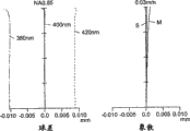
The sectional view of Fig. 1 (a) expression object lens, the aberration curve of object lens in Fig. 1 (b) expression example 1.
The sectional view of Fig. 2 (a) expression object lens, the aberration curve of object lens in Fig. 1 (b) expression example 1.
The sectional view of Fig. 3 (a) expression object lens, the aberration curve of object lens in Fig. 3 (b) expression example 1.
The sectional view of Fig. 4 (a) expression object lens, the aberration curve of object lens in Fig. 4 (b) expression example 1.
The sectional view of Fig. 5 (a) expression object lens, the aberration curve of object lens in Fig. 5 (b) expression example 1.
The sectional view of Fig. 6 (a) expression object lens, the aberration curve of object lens in Fig. 6 (b) expression example 1.
The sectional view of Fig. 7 (a) expression object lens, the aberration curve of object lens in Fig. 7 (b) expression example 1.
Fig. 8 represents to adopt the optic pick-up embodiment diagrammatic sketch of object lens of the present invention.
Fig. 9 represents the sectional view of object lens in the example 8.
Figure 10 represents the aberration curve of object lens in the example 8.
Figure 11 represents the sectional view of object lens in the example 9.
Figure 12 represents the aberration curve of object lens in the example 9.
Figure 13 represents the sectional view of object lens in the example 10.
Figure 14 represents the aberration curve of object lens in the example 10.
Figure 15 represents the sectional view of object lens in the example 11.
Figure 16 represents the aberration curve of object lens in the example 11.
Figure 17 represents the sectional view of object lens in the example 12.
Figure 18 represents the aberration curve of object lens in the example 12.
Figure 19 represents the sectional view of object lens in the example 13.
Figure 20 represents the aberration curve of object lens in the example 13.
Figure 21 represents the sectional view of object lens in the example 14.
Figure 22 represents the aberration curve of object lens in the example 14.
Figure 23 represents the sectional view of object lens in the example 15.
Figure 24 represents the aberration curve of object lens in the example 15.
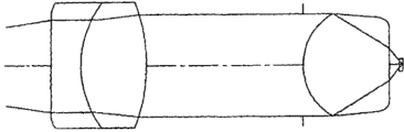
Figure 25 represents the sectional view of coupled lens and object lens in the example 16.
Figure 26 represents the spherical aberration curve of coupled lens and object lens in the example 16.
Figure 27 represents the sectional view of coupled lens and object lens in the example 17.
Figure 28 represents the spherical aberration curve of coupled lens and object lens in the example 17.
Figure 29 represents the sectional view of coupled lens and object lens in the example 18.
Figure 30 represents the spherical aberration curve of coupled lens and object lens in the example 18.
Figure 31 represents the sectional view of coupled lens and object lens in the example 19.
Figure 32 represents the spherical aberration curve of coupled lens and object lens in the example 19.
Figure 33 represents the sectional view of coupled lens and object lens in the example 20.
Figure 34 represents the spherical aberration curve of coupled lens and object lens in the example 20.
Figure 35 represents the sectional view of coupled lens and object lens in the example 21.
Figure 36 represents the spherical aberration curve of coupled lens and object lens in the example 21.
Figure 37 represents the sectional view of coupled lens and object lens in the example 22.
Figure 38 represents the spherical aberration curve of coupled lens and object lens in the example 22.
Figure 39 represents the sectional view of coupled lens and object lens in the example 23.
Figure 40 represents the spherical aberration curve of coupled lens and object lens in the example 23.
Figure 41 represents the sectional view of coupled lens and object lens in the example 24.
Figure 42 represents the spherical aberration curve of coupled lens and object lens in the example 24.
Figure 43 represents the sectional view of coupled lens and object lens in the example 25.
Figure 44 represents the spherical aberration curve of coupled lens and object lens in the example 25.
Figure 45 represents the sectional view of coupled lens and object lens in the example 26.
Figure 46 represents the spherical aberration curve of coupled lens and object lens in the example 26.
Figure 47 represents the sectional view of coupled lens and object lens in the example 27.
Figure 48 represents the spherical aberration curve of coupled lens and object lens in the example 27.
Figure 49 represents the object lens sectional view in the example 28;
Figure 50 represents the aberration curve of object lens in the example 28.
Figure 51 represents the sectional view of object lens in the example 29.
Figure 52 represents the aberration curve of object lens in the example 29.
Figure 53 represents the sectional view of object lens in the example 30.
Figure 54 represents the aberration curve of object lens in the example 30.
Figure 55 represents the sectional view of object lens in the example 31.
Figure 56 represents the aberration curve of object lens in the example 31.
Figure 57 represents to adopt the synoptic diagram of another embodiment of optic pick-up of object lens of the present invention.
Embodiment
To explain embodiments of the invention below.
According to the single object lens of the aspheric surface of first aspect present invention is record and the object lens that reproduce from information recording carrier on information recording carrier, and it is characterized in that satisfying following expression formula.
By the way, object lens of the present invention have an aspheric surface at least.Though can have only a side is aspheric surface, preferably the both sides of object lens all show aspheric surface.Wish that also object lens are made up of one rather than a plurality of lens.
1.1≤d1/f≤3 (1)
Herein, d1 represents the axial width of lens, and f represents focal length.
Above-mentioned expression formula (1) expression obtains the good condition that resembles altitude response, and when attempting to obtain to be not less than 0.65 or condition when preferably being not less than 0.75 bigger numerical aperture, specifically, if the d1/f value is not less than its lower limit, the center thickness of lens just can not be too little, the altitude response of elephant can not decayed, and motion sensitivity can not become big.If the d1/f value is no more than its upper limit, then center thickness is just not too large, and the altitude response of elephant can not decayed yet.By the way, the scope of d1 is preferably between the 2mm-4mm.
In addition, eccentric susceptibility improves.Spherical aberration and coma can obtain gratifying correction.The present invention on optical data recording medium, reproduce or the optic pick-up that writes down in the light source of an emitting light flux is arranged, the light-gathering optics of the luminous flux of a convergent light source emission and a detection are from the reflected light of optical data recording medium or the light detection device of transmitted light.Light-gathering optics has one the object lens of light flux concentration to the information recording surface of optical data recording medium.These object lens are exactly the sort of of the invention described above.By the way, light-gathering optics can also have a coupled lens except that object lens.Optical data recording medium data recording/reproducing device of the present invention has the above-mentioned the sort of optic pick-up of the present invention.In addition, the optical data recording medium data recording/reproducing device can also have the spindle motor and the tracking means of a rotary optical information recording carrier.By the way, the diameter of the diameter in best wavelength according to light source, aperture and object lens obtains the numerical aperture of optic pick-up.By the way, in optic pick-up, the luminous flux that can make predetermined wavelength reads on predetermined optical data recording medium/and the numerical aperture of recorded information can be used as the numerical aperture of optic pick-up, or the numerical aperture of the optical data recording medium foundation of the standard that reads/write down by optic pick-up is as the numerical aperture of optic pick-up.In addition, when only by lens decision numerical aperture, if lens correction in the certain radius scope of lens opening, there not being aberration (for example, wavefront aberration is corrected to 0.07 λ or littler), numerical aperture defines the ratio of radius and focal length for this reason.
It is even more ideal that above-mentioned state expression formula (1) satisfies following expression formula:
1.2≤d1/f≤2.3
In addition, to satisfy following expression formula ideal for above-mentioned state expression formula (1):
1.5≤d1/f≤1.8
In addition, wish that above-mentioned object lens satisfy following state expression formula (2):
f/vd≤0.060 (2)
Herein, vd represents Abbe number.
The condition that state expression formula (2) expression diminishes axial chromatic aberration.Can tackle thus the servo control mechanism that is used for focusing on the wavelength transient state fluctuation of the LASER Light Source that can not accompany or follow, and handle the wavelength spread that has multimode oscillation to cause in the light source.It is better that above-mentioned expression formula (2) satisfies following state expression formula:
f/vd≤0.050
In addition, it is best that above-mentioned expression formula (2) satisfies following state expression formula:
f/vd≤0.035
About the material of lens, preferably use Abbe number to satisfy vd=50 but not the material of vd=35.
Object lens both can be that glass lens also can be a plastic lens.When object lens were plastic lens, preferably the saturation water of lens plastics absorbed and is no more than 0.01%.In addition, preferably adopt wavelength transmissivity to be not less than 85% material to 350-500nm.Wish that also object lens diameter of the present invention is 2.0mm to 4.0mm.As for the material of plastic lens, preferably adopt polyolefin numerical value.Norborene specifically.
In addition, above-mentioned object lens preferably satisfy following state expression formula (3):
1.40≤n (3)
Herein, n is illustrated in the refractive index (material of object lens is to the refractive index of optical source wavelength) of using the wavelength place.
The condition of state expression formula (3) expression refractive index, and when this condition satisfied and refractive index is diminished, the radian of first surface was constant big, this lip-deep motion sensitivity and tilt sensitive degree are also constant big, and the altitude response of elephant is unattenuated.
In addition, above-mentioned object lens preferably satisfy following state expression formula (4):
1.40≤n<1.85 (4)
The condition of state expression formula (4) expression refractive index, and needs not only get in touch with axial light power and also the optic pick-up that interrelates with polarized light power in, because of proofreading and correct the chromatic dispersion that produces, axial width tends to bigger.When n is no more than on it in limited time, refractive index is not too large, and the center thickness of lens do not need very greatly, and this makes and is easy to obtain very light weight and guarantees operating distance.Prescribe a time limit down when n is not less than it, it is too little that refractive index can not become yet, and the radian of first surface can not become greatly, and the altitude response of elephant is unattenuated.
Wish that above-mentioned state expression formula (4) satisfies following state expression formula:
1.50≤n<1.85
It is better to satisfy following expression formula:
1.70≤n<1.85
In addition, above-mentioned object lens preferably satisfy following state expression formula (5):
0.40≤r1/(n·f)≤0.70 (5)
Herein, r1 represents the paraxial radius-of-curvature (preferably being in the paraxial radius-of-curvature of light source one side) on a surface of above-mentioned object lens.
Above-mentioned state expression formula (5) relates generally to the correction of coma, and descend in limited time when r1/ (nf) value is not less than it, r1 can be too not little yet, the flicker that introversive or export-oriented coma causes becomes and is difficult to take place, and prescribe a time limit on it when r1/ (nf) value is no more than, r1 is also not too large, and export-oriented coma is difficult to take place, and also is difficult to produce the back light bright (under flare) of spherical aberration.
Wish that above-mentioned state expression formula (5) satisfies following expression formula:
0.40≤r1/(n·f)≤0.65
The spot diameter that is converged on the recording medium by object lens determines that by k λ/NA when λ represented the wavelength of light source, NA represented the numerical aperture of object lens usually, and k represents proportionality constant.Therefore, when the numerical aperture of using wavelength to be equal to or less than the LASER Light Source of 500nm and object lens do be equal to or greater than 0.65 the time, can make the spot diameter of convergence very little.And therefore can make that the information signal density of record is very high by constituting the optic pick-up that adopts lens of the present invention.In addition, can be equal to or less than 0.2mm by the protective layer thickness that makes recording medium the object lens with little operating distance are provided, make that obtaining light, small and exquisite optic pick-up becomes possibility.
In other words; be not less than 0.65 in the numerical aperture of optical data recording medium side and (preferably be not less than 0.7 when the wavelength that adopts (wavelength of the luminous flux that sends from light source) is no more than 500nm or object lens; be not less than 0.75 better) time; or when being used to have thickness and being no more than the optical data recording medium of protective seam of 0.2mm, object lens of the present invention, optic pick-up and optical data recording medium data recording/reproducing device are all very suitable.
When above-mentioned object lens are made by material, can obtain the optic pick-up of light weight, and realize large-tonnage product cheaply.
The single object lens of another kind of preferred aspheric surface are a kind of object lens that are used on information recording carrier record or reproduce; and these object lens are characterised in that the wavelength of employing is 500nm or shorter; information recording carrier has a thickness to be equal to or less than the protective seam of 0.2mm; the numerical aperture of object lens is equal to or greater than 0.65, preferably is equal to or greater than 0.75.
Best aforesaid object lens satisfy following state expression formula (6), and this formula is expressed as and obtains the good required condition of altitude response that resembles, and operation wherein is identical with conditional expression (1):
1.1≤d1/f≤3 (6)
Herein, d1 represents the axial width of lens, and f represents focal length.
Best aforesaid object lens satisfy following state expression formula (7), and this formula is expressed as handles the required condition of axial chromatic aberration, and operation wherein is identical with conditional expression (2):
f/vd≤0.060 (7)
Herein, vd represents Abbe number.
Best aforesaid object lens satisfy following state expression formula (8), and this formula is represented the condition that refractive index should satisfy, and operation wherein is identical with conditional expression (3):
1.40≤n (8)
Herein, n represents using the refractive index of wavelength.
Best aforesaid object lens satisfy following state expression formula (9).This formula is represented the condition that refractive index should satisfy, and operation wherein is identical with conditional expression (4):
1.40≤n<1.85 (9)
Best aforesaid object lens satisfy following state expression formula (10), and this formula relates generally to the correction of coma, and operation wherein is identical with conditional expression (5):
0.40≤r1/(n·f)≤0.70 (10)
Herein, r1 represents the paraxial radius-of-curvature on the Lights section.
The single object lens of another kind of preferred aspheric surface are a kind of object lens that are used on information recording carrier record or reproduce, and these object lens are characterised in that the numerical aperture of object lens is equal to or greater than 0.75 and made by plastic material.
Best aforesaid object lens satisfy following state expression formula (11), and this formula is expressed as and obtains the good required condition of altitude response that resembles, and operation wherein is identical with conditional expression (1):
1.1≤d1/f≤3 (11)
Herein, d1 represents the axial width of lens, and f represents focal length.
Best aforesaid object lens satisfy following state expression formula (12), and this formula is expressed as the less required condition of axial chromatic aberration that makes, and operation wherein is identical with conditional expression (2):
f/vd≤0.060 (12)
Herein, vd represents Abbe number.
Best aforesaid object lens satisfy following state expression formula (13), and this formula is represented the condition that refractive index should satisfy, and operation wherein is identical with conditional expression (3):
1.40≤n (13)
Herein, n represents using the refractive index of wavelength.
Best aforesaid object lens satisfy following state expression formula (14).The condition that formula (14) expression refractive index should satisfy, operation wherein is identical with conditional expression (4):
1.40≤n<1.85 (14)
Best aforesaid object lens satisfy following state expression formula (15), and this formula relates generally to the correction of coma, and operation wherein is identical with conditional expression (5):
0.40≤r1/(n·f)≤0.70 (15)
Herein, r1 represents the paraxial radius-of-curvature on the Lights section.
The single object lens of another kind of preferred aspheric surface are a kind of object lens that are used on information recording carrier record or reproduce, and these object lens are characterised in that the numerical aperture of object lens is equal to or greater than 0.65, preferably are equal to or greater than 0.75, and satisfy following formula (16):
n≥1.85 (16)
Herein, n represents using the refractive index of wavelength.
The condition of above-mentioned expression formula (16) expression refractive index.By using the material of high index of refraction, the radius-of-curvature on the first surface is increased, and thereby the distant view angle is diminished.Therefore, an advantage that is easy to handle metal melting is arranged when preparing lens by fusion.In addition, in the situation of light pick-up, the most important axial light power that just needs, the use of high-index material makes and is easy to proofread and correct the high-order spherical aberration.
Best aforesaid object lens satisfy following state expression formula (17), and this formula is expressed as and obtains the good required condition of altitude response that resembles, and operation wherein is identical with conditional expression (1):
1.1≤d1/f≤3 (17)
Herein, d1 represents the axial width of lens, and f represents focal length.
Best aforesaid object lens satisfy following state expression formula (18), and this formula relates generally to the correction of coma, and operation wherein is identical with conditional expression (5):
0.40≤r1/(n·f)≤0.70 (18)
Herein, r1 represents the paraxial radius-of-curvature on the Lights section.
The single object lens of another kind of preferred aspheric surface are a kind of object lens that are used on information recording carrier record or reproduce, and these object lens are characterised in that the numerical aperture of object lens is 0.65, preferably are equal to or greater than 0.75, and satisfy following formula (19):
1.40≤n<1.85 (19)
Herein, n represents using the refractive index of wavelength.
The aforesaid state expression formula is represented the condition of refractive index.About its operation, identical with expression formula (4).
Be preferably in a diffraction region is set on the light-gathering optics in the optic pick-up of the present invention.Though a diffraction region preferably is set on the object lens of light-gathering optics, also can be combined into one in light-gathering optics only has the optical element of diffraction region or a diffraction region is set on another optical element, constitute a light-gathering optics, as coupled lens.By the way, also a Difraction surface can only be set on a side of single coupled lens.Because this structure, can avoid the decay of the wavefront aberration that surperficial degree of eccentricity causes.
When only passing through a spherical surface or only passing through the spherical aberration of the single object lens calibration standard wavelength in the aspheric surface birefringence system, usually the wavelength that is shorter than the standard wavelength is produced aberration under the axle, and the wavelength generation axle of being longer than the standard wavelength is gone up aberration.But under the situation of object lens with Difraction surface, when to standard wavelength's spherical aberration corrector, may produce the machinery opposite, produce upward aberration of axle promptly to the aberration on the wavelength generation axle that is shorter than the standard wavelength, and to the wavelength of being longer than the standard wavelength with object lens in the dioptric system.Therefore, in the situation of above-mentioned object lens, even for fluctuation of transient state wavelength such as mode hopping, also can be by merging diffraction power and as the phase function coefficient of diffraction lens, and therefore by the spherical aberration correction aberration being realized demonstrating the object lens of function admirable, wherein diffraction power is by suitably selecting asphericity coefficient as non-spherical lens.
The numerical aperture of above-mentioned object lens is for being equal to or greater than 0.65; preferably be equal to or greater than 0.75; when adopting 500nm or shorter wavelength; and when using protective layer thickness to be equal to or less than the information recording carrier of 0.2mm; can use wavelength to be no more than the short wavelength's of 500nm LASER Light Source; make the numerical aperture of object lens be equal to or greater than 0.65, and make the spot diameter of convergent beam less.Can realize recording information signal to high-density by the optic pick-up that structure has lens of the present invention thus.In addition, can be thinner than by the protective layer thickness that makes recording medium or equal 0.2mm provides the object lens with little operating distance, obtains lightweight, small and exquisite optic pick-up becomes possibility.
In addition, in every kind of above-mentioned object lens, be preferably in outer placing flange portion is set, and be arranged on the outer flange of placing and preferably have one perpendicular to upwardly extending of the side of optical axis.Because be arranged on the outer flange of placing, object lens can be attached to optic pick-up at an easy rate, and can link object lens more accurately on flange portion by the face that almost extends perpendicular to the direction of optical axis on an edge is set.
In addition, every kind of optic pick-up of the present invention all is a kind of device that has light source and object lens therein, the light flux concentration that object lens send light source is to the information recording surface of information recording carrier, and carry out recording of information and/or reproduction at information recording carrier by surveying the light that sends from information recording carrier, wherein the single object lens of aspheric surface are set to above-mentioned object lens.
In addition, every kind of optic pick-up of the present invention all is a kind of device that has light source, coupled lens and object lens therein, the angle of divergence of the diverging light that coupled lens change light source sends, object lens converge to luminous flux the information recording surface of information recording carrier through coupled lens, and carry out recording of information and/or reproduction at information recording carrier by surveying the light that sends from information recording carrier, wherein coupled lens has the function of proofreading and correct the object lens aberration, and the single object lens of aspheric surface are set to above-mentioned object lens.
When the single object lens of aspheric surface are used as object lens, can be applicable to the object lens of high density recording/transcriber, but because the single object lens in the dioptric system also cause being in the following axial chromatic aberration of short wavelength's part.But, axial chromatic aberration can be proofreaied and correct by the coupled lens in the aforementioned optic pick-up.If promptly the axial chromatic aberration of coupled lens is in more than the short wavelength, then the axial chromatic aberration of object lens can reduce.Thus, can obtain a kind of optic pick-up with an optical system together with above-mentioned object lens, wherein the axial chromatic aberration of optical system is by simple correct-by-construction.
In this case, coupled lens can be collimated into the luminous flux that sends from light source the luminous flux of most of collimation.This structure make optic pick-up system assembling and regulate simpler.Be that coupled lens also can be a kind of collimation lens.
Can also be arranged to make the aberration of the synthesis system of object lens and coupled lens to satisfy following expression formula (20):
δfb·NA
2≤0.25μm(δfb>0) (20)
Herein, δ fb represents that NA represents the numerical aperture of object lens in the dish side when wavelength change of synthesis system focal position (μ m) during from standard wavelength change+1nm.
Preferably satisfy following expression formula (20) ':
0.02μm≤δfb·NA
2≤0.15μm(δfb>0) (20)’
Each above-mentioned structure relates to the correction of carrying out aberration by coupled lens.When with the oscillation wavelength of about 400nm operation short wavelength laser semiconductor, be the serious problems that to allow by the micro-axial chromatic aberration that on object lens, causes that moves of wavelength.The reason of problem is explained as follows.When the operation short wavelength, very big for the small fluctuation variations in refractive index of common lens material wavelength.The result is that the defocus amount that focuses on is very big.But about the depth of focus of object lens, the wavelength of employing (λ) is short more, and depth of focus is more little, can be by k λ/NA
2Know (k is a proportionality constant) by inference, even very little defocus amount does not allow yet.In ISOM/ODS ' 99PostdeadlinePoster Papersde Session WD26, show the high frequency stack of 0.7mm spectrum width for GaN blue streak semiconductor laser.It is desirable to high frequency stack is controlled to about 0.02 λ rms to the wavefront aberration of optic pick-up system.Suppose to be proofreaied and correct, then obtain for aforementioned necessary axial chromatic aberration level of corrections for the spherical aberration of color.Therefore, when the standard wavelength is numerical aperture on 400nm and the NA indicating panel part, rises and to be controlled at about 0.15 μ m/NA to the axial chromatic aberration of synthesis system for the wavelength of 1nm
2, be used for the high frequency stack (FWMH) of 0.7nm spectrum width is controlled to 0.02 λ rms to wavefront aberration.On the other hand, the axial chromatic aberration of synthesis system does not always need crooked correction, and wavefront aberration can remain in the scope of a permission.When object lens in the present invention are a simple lens in the dioptric system, can be on the occasion of constituting a coupled lens by making axial chromatic aberration in simple mode for the long wavelength, even also be so in synthesis system because object lens for long wavelength's axial chromatic aberration be on the occasion of.For example, when coupled lens is made up of the balsaming lens of a group and two elements, compare with the color correction completely of synthesis system, the magnification of each lens element of coupled lens can be very little, this produce a kind of about aberration aspect function admirable coupled lens and be easy to make.Even under for the situation of coupled lens as the diffraction lens correction of color, the magnification of diffraction surfaces can be very little, and the interval of diffraction endless belt is very big thus, and can make the diffraction lens of high-diffraction efficiency at an easy rate.For this reason, set up the lower limit of aforesaid state expression formula.
In addition, preferably satisfy the expression formula of following magnification m about synthesis system:
0.1≤|m|≤0.5(m<0)
Herein, m represents the magnification of the synthesis system of object lens and coupled lens.
Prescribe a time limit when magnification is not less than the following of above-mentioned state expression formula, synthesis system is compact, and prescribes a time limit when magnification is not higher than, and coupled lens is better aspect aberration.
Coupled lens both can be made of single component, also can constitute by a plurality of assemblies, and coupled lens preferably one of one group and two elements structure.Because one group and two elements structure of above-mentioned coupled lens, so coupled lens simple in structure and cause coupled lens to be easy to make.When one group of use and two elements structure, producing tangible axial chromatic aberration and keeping logitudinal magnification more than short wavelength's part and below long wavelength's part.Consequently can advantageously proofread and correct object lens and axial chromatic aberration long wavelength part more than following for short wavelength's part, keep the logitudinal magnification of synthesis system simultaneously, this is favourable for fluctuation of transient state wavelength such as mode hopping.When above for short wavelength part and long wavelength's part is following when producing this axial chromatic aberration, the curvature with coupled lens cemented surface of disperse function is tending towards change greatly.Therefore, if standard wavelength's spherical aberration is controlled, then produce the above and following spherical aberration of long wavelength's part of short wavelength's part in a large number.The result is that the short wavelength's part and the long wavelength's aberration partly that produce on the object lens are eliminated, and can the spherical aberration synthesis system control very for a short time under the situation of wavelength fluctuation.
By the way, coupled lens preferably has an aspheric surface.Aspheric surface both can be arranged on a side, also can be arranged on both sides.
Because above-mentioned coupled lens is to have aspheric one group and a two elements structure, thus can make the numerical aperture of coupled lens bigger by aspheric aberration correction function, and obtain the synthesis system of short compactness of total length.
Because above-mentioned coupled lens has a diffraction surfaces, so can obtain coupled lens efficiently with a simple lens simple in structure by adding a diffraction surfaces to the plastic aspherical element lens.By the way, also can be by proofread and correct the spherical aberration fluctuation that produces on each optical surface in optical system at mobile coupled lens on the optical axis direction.For example, can mobile coupled lens, the RF amplitude of following the tracks of reproducing signal simultaneously makes the spherical aberration that produces in optical system to proofread and correct in the mode of the best.When the spherical aberration fluctuation that produces on each optical surface of optical system; have fluctuation based on the oscillation wavelength subtle change of light source; fluctuation based on steady change; the fluctuation that changes based on humidity is based on the fluctuation of the subtle change of information recording carrier protective layer thickness with based on aforementioned described comprehensive fluctuation.Preferably coupled lens moves at optical axis direction, make when spherical aberration when optical system rises to a bigger side, apart from object lens apart from increasing, and coupled lens is mobile on optical axis direction, make when spherical aberration when optical system rises to a less side, can reduce apart from the distance of object lens.By the way, as for coupled lens moving on optical axis direction, preferably optic pick-up has the mobile device of a mobile coupled lens.As mobile device, can adopt (voice-oil-shaped) actuator and piezo-activator.
By the way, above-mentioned every kind of optic pick-up converges to the information recording surface of information recording carrier to the luminous flux that sends from light source through object lens, and can recorded information on the information recording carrier and/or from the information recording carrier information reproduction.
Above-mentioned optical data recording medium for example comprises various CDs, as CD, and CD-R, CD-RW, CD-Video and CD-ROM, various DVD are as DVD, DVD-ROM, DVD-RAM, DVD-R and DVD-RW and plate-like information recording carrier, as MD, and comprise the high density information recording medium of the novelty that increases with regard to recording density.
Below with reference to accompanying drawings embodiments of the invention are done an explanation.Fig. 8 is the optic pick-up structure diagram of the embodiment of the invention.
Optic pick-up among Fig. 8 is a kind of device that adopts the single object lens of of the present invention pair of aspheric surface as object lens, wherein be provided with the semiconductor laser 3 of representing light source, from the light flux concentration of coupled lens 2 object lens 2 to the information recording surface 5 of information recording carrier, receive from the photo-detector 4 of the light of information recording surface 5 reflections of information recording carrier.
Optic pick-up among Fig. 8 also disposes the beam splitter 6 of the photolysis of reflecting from information recording surface 5 to photo-detector 4, quarter wave plate 7 between coupled lens 2 and object lens 1, be positioned at object lens 8 diaphragm 8 before, be used for the cylindrical lens 9 and the actuator 10 of Focus tracking.In other words, in the present embodiment, a beam splitter is arranged in the light-gathering optics, a coupled lens, a quarter wave plate, object lens and a diaphragm.By the way, in the present invention, can think that beam splitter is not included in the light-gathering optics.
Coupled lens 2 can also be a kind of collimation lens, the divergence light flux of incident is collimated into the luminous flux that almost is parallel to optical axis.In this case, preferably light source 3 or collimation lens 2 are arranged to move adjusting on the direction of collimation lens optical axis, make the luminous flux that sends from collimation lens 2 can be close to collimation.
As mentioned above, optic pick-up of the present invention both can be transformed into the collimation lens that is mainly collimated light by the luminous flux of dispersing that a handle sends from light source and the object lens that collimated light converges to information recording surface had been formed, also the angle of the diverging light that can be sent by the change light source of a representative convergent lens and be transformed into diverging light or the coupled lens of converging light and the light flux concentration that coupled lens sends formed to the object lens of information recording surface.Optic pick-up can also only be made up of object lens (infinite conjugate objective lens), and object lens converge to information recording surface to the diverging light that light source sends.
Then, can obtain a kind of optic pick-up that can carry out high density recording and reproduction by utilizing the single object lens of aspheric surface of the present invention to CD.
Example
Next, to making an explanation about the routine 1-15 of object lens of the present invention and optic pick-up and about the routine 16-27 of coupled lens and optic pick-up.By the way, the structure example of optic pick-up is similar to the embodiment shown in Fig. 8.Optic pick-up of the present invention by noise spectra of semiconductor lasers carry out the standard wavelength selection (light source is set), set up for example use the deletion coupled lens or collimation lens as coupled lens, set up an aperture diaphragm 8 and arrange each position component and settle object lens and coupled lens obtains, make all to be satisfied in structure and the condition described in following each example.
At first explain the example of object lens.The data of example 1-15 are listed in the table below 1.By the way, in routine 1-15, example 6,9 and 15 is at plastic lens, and remaining is at glass lens.Optical data recording medium in the example 5 does not have transparent substrates.Optical data recording medium in other example has the thick transparent substrates of 0.1mm.
Table 1

Table 1 (continuing)

Table 1 (continuing)

Object lens in example 1-4, example 6 and the example 7 are unlimited object lens for the standard wavelength of 400nm, and the object lens in routine 8-15, example 6 and the example 7 are unlimited object lens for the standard wavelength of 405nm.In the middle of each of example 6 and 9, suppose to place a thickness information recording carrier protective seam that is 0.1mm and the operating distance that is not less than 0.1mm is set between the face, and object lens are made of plastic material resembling of object lens and information recording carrier.Object lens in the example 5 are unlimited object lens for the standard wavelength of 660nm.
Be provided with a diffraction region in the example 15.By the way, be expressed as the altitude response of the vocabulary aspect of " from axle ", " wavefront aberration " in the table 1.Table 1 shows that the altitude response of elephant in the routine 1-example 15 is favourable.In example 8, the wavefront aberration that the first surface of eccentric 1 μ m causes is 0.021 λ, and this makes eccentric susceptibility very outstanding, because it is less than 0.035 λ.Even Polarization-Sensitive in other embodiments degree is also very good.
About the aspheric surface in this example, when representing the direction of optical axis with the x axle, can be represented by the formula, representing by h that perpendicular to the height on the optical axis direction radius-of-curvature on surface is represented that by r suppose that k represents the constant of the cone, A2i represents asphericity coefficient:
Example 1
Lens data is suitable for table 2, and asphericity coefficient is suitable for table 3.The lens of example 1 are shown in Fig. 1, and Fig. 1 (a) is a sectional view, and Fig. 1 (b) is an aberration curve.
λ (wavelength)=400nm
f=1.765mm
NA=0.85
Magnification=0
Table 2
| r(mm) | d(mm) | | vd | ||
| 1 *2 *34 | 1.72078-1.92753∞∞ | 3.1500.2130.1000.000 | 1.856141.62158 | 37.030.0 |
*: aspheric surface
Table 3

(example 2)
Lens data is listed in table 4, and asphericity coefficient is listed in table 5.The lens of example 2 are shown in Fig. 2, and wherein Fig. 2 (a) is a sectional view, and Fig. 2 (b) is an aberration curve.
λ (wavelength)=400nm
f=1.765mm
NA=0.75
Magnification=0
Table 4
| r(mm) | d(mm) | | vd | ||
| 1 *2 *34 | 1.72793-2.27646∞∞ | 3.0370.2720.1000.000 | 1.856141.62158 | 37.030.0 |
*: aspheric surface
Table 5
(example 3)
Lens data is listed in table 6, and asphericity coefficient is listed in table 7.The lens of example 3 are shown in Fig. 3, and wherein Fig. 3 (a) is a sectional view, and Fig. 3 (b) is an aberration curve.
λ (wavelength)=400nm
f=1.765mm
NA=0.85
Magnification=0
Table 6
| r(mm) | d(mm) | | vd | ||
| 1 *2 *34 | 1.51143-1.44415∞∞ | 2.9460.2670.1000.000 | 1.716671.62158 | 53.230.0 |
*: aspheric surface
Table 7

(example 4)
Lens data is listed in table 8, and asphericity coefficient is listed in table 9.The lens of example 4 are shown in Fig. 4, and wherein Fig. 4 (a) is a sectional view, and Fig. 4 (b) is an aberration curve.
λ (wavelength)=400nm
f=1.765mm
NA=0.75
Magnification=0
Table 8
| r(mm) | d(mm) | | vd | ||
| 1 * | 1.51629 | 2.801 | 1.71667 | 53.2 | |
| 2 * | -1.74496 | 0.342 | |||
| 3 | ∞ | 0.100 | 1.62158 | 30.0 | |
| 4 | ∞ | 0.000 |
*: aspheric surface
Table 9

(example 5)
Lens data is listed in table 10, and asphericity coefficient is listed in table 11.The lens of example 5 are shown in Fig. 5, and wherein Fig. 5 (a) is a sectional view, and Fig. 5 (b) is an aberration curve.
λ (wavelength)=660nm
f=0.131mm
NA=0.83
Magnification=-0.1456
Table 10
| r(mm) | d(mm) | | vd | ||
| 1 * | 0.115 | 0.226 | 1.79998 | 40.9 | |
| 2 * | -1.47 | 0.000 |
*: aspheric surface
Table 11

(example 6)
Lens data is listed in table 12, and asphericity coefficient is listed in table 13.The lens of example 6 are shown in Fig. 6, and wherein Fig. 6 (a) is a sectional view, and Fig. 6 (b) is an aberration curve.
λ (wavelength)=400nm
f=2.647mm
NA=0.85
Magnification=0
Table 12
| r(mm) | d(mm) | | vd | ||
| 1 * | 1.97771 | 4.748 | 1.56119 | 56.0 | |
| 2 * | -0.81768 | 0.300 | |||
| 3 | ∞ | 0.100 | 1.62158 | 30.0 | |
| 4 | ∞ | 0.000 |
*: aspheric surface
Table 13

(example 7)
Lens data is listed in table 14, and asphericity coefficient is listed in table 15.The lens of example 7 are shown in Fig. 7, and wherein Fig. 7 (a) is a sectional view, and Fig. 7 (b) is an aberration curve.
λ (wavelength)=400nm
f=1.765mm
NA=0.85
Magnification=0
Table 14
| r(mm) | d(mm) | | vd | ||
| 1 * | 1.53773 | 2.500 | 1.85614 | 37.0 | |
| 2 * | -21.60833 | 0.380 | |||
| 3 | ∞ | 0.100 | 1.62158 | 30.0 | |
| 4 | ∞ | 0.000 |
*: aspheric surface
Table 15

(example 8)
Lens data and asphericity coefficient are listed in table 16.The object lens cross section of example 8 is shown in Fig. 9, and aberration curve is shown in Figure 10.
Table 16
Example 8
λ (wavelength)=405nm
f=1.765mm
NA=0.85
Magnification=0
| r(mm) | d(mm) | | vd | ||
| 1 * | 1.43376 | 2.750 | 1.71558 | 53.2 | |
| 2 * | -2.11753 | 0.290 | |||
| 3 | ∞ | 0.100 | 1.61950 | 30.0 | |
| 4 | ∞ | 0.000 |
*: aspheric surface

(example 9)
Lens data and asphericity coefficient are listed in table 17.The object lens cross section of example 9 is shown in Figure 11, and aberration curve is shown in Figure 12.
Table 17
Example 9
λ (wavelength)=405nm
f=1.765mm
NA=0.85
Magnification=0
| r(mm) | d(mm) | | vd | ||
| 1 * | 1.17503 | 2.602 | 1.52523 | 59.2 | |
| 2 * | -1.04152 | 0.357 | |||
| 3 | ∞ | 0.100 | 1.61950 | 30.0 | |
| 4 | ∞ | 0.000 |
*: aspheric surface

(example 10)
Lens data and asphericity coefficient are listed in table 18.The object lens cross section of example 10 is shown in Figure 13, and aberration curve is shown in Figure 14.
Table 18
Example 10
λ (wavelength)=405nm
f=1.765mm
NA=0.85
Magnification=0
| r(mm) | d(mm) | | vd | ||
| 1 * | 1.07547 | 2.657 | 1.44260 | 95.0 | |
| 2 * | -0.69088 | 0.366 | |||
| 3 | ∞ | 0.100 | 1.61950 | 30.0 | |
| 4 | ∞ | 0.000 |
*: aspheric surface
(example 11)
Lens data and asphericity coefficient are listed in table 19.The object lens cross section of example 11 is shown in Figure 15, and the difference curve is shown in Figure 16.
λ (wavelength)=405nm
f=1.765mm
NA=0.85
Magnification=0
Table 19
Example 11
| r(mm) | d(mm) | | vd | ||
| 1 * | 1.15821 | 2.647 | 1.50716 | 81.6 | |
| 2 * | -0.90947 | 0.346 | |||
| 3 | ∞ | 0.100 | 1.61950 | 30.0 | |
| 4 | ∞ | 0.000 |
*: aspheric surface

(example 12)
Lens data and asphericity coefficient are listed in table 20.The object lens cross section of example 12 is shown in Figure 17, and aberration curve is shown in Figure 18.
Table 20
Example 12
λ (wavelength)=405nm
f=1.765mm
NA=0.85
Magnification=0
| r(mm) | d(mm) | | vd | ||
| 1 * | 1.69377 | 2.400 | 2.15857 | 21.2 | |
| 2 * | 2.36431 | 0.361 | |||
| 3 | ∞ | 0.100 | 1.61950 | 30.0 | |
| 4 | ∞ | 0.000 |
*: aspheric surface

(example 13)
Lens data and asphericity coefficient are listed in table 21.The object lens cross section of example 13 is shown in Figure 19, and aberration curve is shown in Figure 20.
Table 21
Example 13
λ (wavelength)=405nm
f=1.765mm
NA=0.85
Magnification=0
| r(mm) | d(mm) | | vd | ||
| 1 * | 2.30000 | 3.650 | 2.15857 | 21.2 | |
| 2 * | -2.73024 | 0.200 | |||
| 3 | ∞ | 0.100 | 1.61950 | 30.0 | |
| 4 | ∞ | 0.000 |
*: aspheric surface

(example 14)
Lens data and asphericity coefficient are listed in table 22.The object lens cross section of example 14 is shown in Figure 21, and aberration curve is shown in Figure 22.
Table 22
Example 14
λ (wavelength)=405nm
f=1.765mm
NA=0.85
Magnification=0
| r(mm) | d(mm) | | vd | ||
| 1 * | 2.64228 | 3.919 | 2.34860 | 16.6 | |
| 2 * | -3.55612 | 0.200 | |||
| 3 | ∞ | 0.100 | 1.61950 | 30.0 | |
| 4 | ∞ | 0.000 |
*: aspheric surface

(example 15)
Lens data and asphericity coefficient are listed in table 23.The object lens cross section of example 15 is shown in Figure 23, and aberration curve is shown in Figure 24.
Table 23
Example 15
λ (wavelength)=405nm
f=1.765mm
NA=0.85
Magnification=0
| r(mm) | d(mm) | n | vd | |
| 1 ( |
1.23647 | 2.532 | 1.52523 | 59.5 |
| 2 (aspheric surfaces 2) | -1.18419 | 0.336 | ||
| 3 | ∞ | 0.100 | 1.61950 | 30.0 |
| 4 | ∞ | 0.000 |
| |
Diffraction surfaces 1 |
| K=-0.68816A 4=0.17621E-01A 6=0.32160E-02A 8=0.17762E-02A 10=0.28747E-03A 12=-0.17669E-03A 14=0.94949E-04A 16=0.17955E-04 | b 2=-0.20985E-01b 4=-0.26478E-02b 6=-0.31346E-03b 8=-0.63327E-04b 10=-0.45002E-04b 12=-0.20458E-04b 14=-0.10510E-04b 12=0.36615E-05 |
| Aspheric surface 2 |
| K=-41.704463A 4=0.362699E+00A 6=-0.534069E+00A 8=0.354745E+00A 10=-0.793612E-01A 12=-0.252257E-03 |
By the way, diffraction surfaces can be expressed from the next into path difference function phi b (also applying to the example 26 of explained later).In this case, h is illustrated in perpendicular to the height on the optical axis direction, and b represents the coefficient of path difference function:
As mentioned above, in routine 1-15, can obtain a kind of single object lens of aspheric surface of the object lens as optic pick-up, have big numerical aperture and the good altitude response that resembles.For example, can obtain a kind of single object lens, wherein numerical aperture is 0.85 for the wavelength of 400nm, and the wavefront aberration rms that resembles height when being 1 ° for the visual angle is 0.07 λ (λ is a wavelength), shown in example 1.Promptly can obtain a kind of single object lens of aspheric surface that are used for light pick-up dress, wherein, numerical aperture is equal to or greater than 0.65 and have good phase altitude response, is applicable to high density recording and transcriber.
In addition, in routine 1-15, can reach good eccentric susceptibility, and spherical aberration corrector and coma satisfactorily.
Next will describe the example boundary of coupled lens.Following table 24 is listed the data of routine 16-27.By the way, the same in the object lens in the example 16,17,20,21 and 22 and the example 8, the same in the object lens in the example 18,19,23,24,25 and 26 and the example 9, the same in the object lens in the example 27 and the example 13.
Table 24
| Example | 16 | 17 | 18 | 19 | 20 | 21 |
| The material of object lens | Glass | Glass | Plastics | Plastics | Glass | Glass |
| The focal length of object lens | 1.765 | 1.765 | 1.765 | 1.765 | 1.765 | 1.765 |
| The NA of object lens | 0.85 | 0.85 | 0.85 | 0.85 | 0.85 | 0.85 |
| The standard wavelength | 405nm | 405nm | 405nm | 405nm | 405nm | 405nm |
| The structure of coupled lens | Two spheres | Two spheres | Two spheres | Two spheres | Two aspheric surfaces | Two aspheric surfaces |
| The angle of divergence from the luminous flux of coupled lens outgoing | The collimated light flux | The collimated light flux | The collimated light flux | The collimated light flux | The collimated light flux | The collimated light flux |
| 0.1≦|m|≦0.5(m<0) | 0.20 | 0.13 | 0.20 | 0.13 | 0.33 | 0.20 |
| δfb·NA 2≦0.25μm≦0.02μm≦δfb·NA 2≦0.15μm | 0.14 | 0.087 | 0.16 | 0.12 | 0.071 | 0.034 |
| (δfb) | 0.19 | 0.12 | 0.22 | 0.17 | 0.098 | 0.047 |
Table 24 (continuing)
| Example | 22 | 23 | 24 | 25 | 26 | 27 |
| The material of object lens | Glass | Plastics | Plastics | Plastics | Plastics | The glass of high index of refraction |
| The focal length of object lens | 1.765 | 1.765 | 1.765 | 1.765 | 1.765 | 1.765 |
| The NA of object lens | 0.85 | 0.85 | 0.85 | 0.85 | 0.85 | 0.85 |
| The standard wavelength | 405nm | 405nm | 405nm | 405nm | 405nm | 405nm |
| The structure of coupled lens | Two aspheric surfaces | Two aspheric surfaces | Two aspheric surfaces | Two aspheric surfaces | Two aspheric surfaces | Two aspheric surfaces |
| The angle of divergence from the luminous flux of coupled lens outgoing | The collimated light flux | The collimated light flux | The collimated light flux | The collimated light flux | The collimated light flux | The collimated light flux |
| 0.1≦|m|≦0.5(m<0) | 0.13 | 0.33 | 0.20 | 0.13 | 0.29 | 0.10 |
| δfb·NA 2≦0.25μm0.02μm≦δfb·NA 2≦0.15μm | 0.0031 | 0.10 | 0.060 | 0.031 | 0.12 | 0.06 |
| (δfb) | 0.0043 | 0.14 | 0.083 | 0.043 | 0.17 | 0.08 |
(example 16)
Lens data and asphericity coefficient are listed in table 25.One group and the coupled lens of two elements structure and the sectional view of object lens are shown in Figure 25 in the example 16, and the spherical aberration curve is shown in Figure 26.
Table 25
| |
Aspheric surface 2 |
| K=-0.452646A 4=0.571669E-2A 6=-0.591147E-2A 8=0.721339E-2A 10=-0.398819E-2A 12=0.390519E-3A 14=0.446956E-3A 16=-0.135385E-3 | K=-185.751580A 4=0.281279A 6=-0.742134A 8=0.667680A 10=-0.195290A 12=-0.252228E-3 |
(example 17)
Lens data and asphericity coefficient are listed in table 26.One group and the coupled lens of two elements structure and the sectional view of object lens are shown in Figure 27 in the example 17, and the spherical aberration curve is shown in Figure 28.
Table 26
| |
Aspheric surface 2 |
| K=-0.452646A 4=0.571669E-2A 6=-0.591147E-2A 8=0.721339E-2A 10=-0.398819E-2A 12=0.390519E-3A 14=0.446956E-3A 16=-0.135385E-3 | K=-185.751580A 4=0.281279A 6=-0.742134A 8=0.667680A 10=-0.195290A 12=-0.252228E-3 |
(example 18)
Lens data and asphericity coefficient are listed in table 27.One group and the coupled lens of two elements structure and the sectional view of object lens are shown in Figure 29 in the example 18, and the spherical aberration curve is shown in Figure 30.
Table 27

| |
Aspheric surface 2 |
| K=-0.682004A 4=0.180213E-1A 6=-0.368416E-2A 8=0.140365E-2A 10=0.342876E-3A 12=-0.311534E-4A 14=0.103341E-3A 16=0.141728E-4 | K=-29.373780A 4=0.297543A 6=-0.423018A 8=0.295535A 10=-0.829290E-1A 12=-0.252257E-3 |
(example 19)
Lens data and asphericity coefficient are listed in table 28.One group and the coupled lens of two elements structure and the sectional view of object lens are shown in Figure 31 in the example 19, and the spherical aberration curve is shown in Figure 32.
Table 28

| |
Aspheric surface 2 |
| K=-0.682004A 4=0.180213E-1A 6=0.368416E-2A 8=0.140365E-2A 10=0.342876E-3A 12=-0.311534E-4A 14=0.103341E-3A 16=0.141728E-4 | K=-29.373780A 4=0.297543A 6=-0.423018A 8=0.295535A 10=-0.829290E-1A 12=-0.252257E-3 |
(example 20)
Lens data and asphericity coefficient are listed in table 29.One group and the coupled lens of two elements structure and the sectional view of object lens are shown in Figure 33 in the example 20, and the spherical aberration curve is shown in Figure 34.
Table 29

| |
|
Aspheric surface 3 |
| K=0.270078A 4=0.425585E-3A 6=-0.968014E-3A 8=0.315494E-3A 10=-0.970417E-4 | K=-0.452646A 4=0.571669E-2A 6=-0.591147E-2A 8=0.721339E-2A 10=-0.398819E-2A 12=0.390519E-3A 14=0.446956E-3A 16=-135385E-3 | K=-185.751580A 4=0.281279A 6=-0.742134A 8=0.667680A 10=-0.195290A 12=-0.252228E-3 |
(example 21)
Lens data and asphericity coefficient are listed in table 30.One group and the coupled lens of two elements structure and the sectional view of object lens are shown in Figure 35 in the example 16, and the spherical aberration curve is shown in Figure 36.
Table 30

| |
|
Aspheric surface 3 |
| K=0.699858A 4=-0.53797E-3A 6=-0.352488E-3A 8=0.595790E-4A 10=-0.152115E-4 | K=-0.452646A 4=0.571669E-2A 6=-0.591147E-2A 8=0.721339E-2A 10=-0.398819E-2A 12=0.390519E-3A 14=0.446956E-3A 16=-0.135385E-3 | K=-185.751580A 4=0.281279A 6=-0.742134A 8=0.667680A 10=-0.195290A 12=-0.252228E-3 |
(example 22)
Lens data and asphericity coefficient are listed in table 31.One group and the coupled lens of two elements structure and the sectional view of object lens are shown in Figure 37 in the example 22, and the spherical aberration curve is shown in Figure 38.
Table 31

| |
|
Aspheric surface 3 |
| K=0.980965A 4=-0.719068E-3A 6=-0.177543E-3A 8=0.364218E-4A 10=-0.120077E-4 | K=-0.452646A 4=0.571669E-2A 6=-0.591147E-2A 8=0.721339E-2A 10=-0.398819E-2A 12=0.390519E-3A 14=0.446956E-3A 16=-0.135385E-3 | K=-185.751580A 4=0.281279A 6=-0.742134A 8=0.667680A 10=-0.195290A 12=-0.25228E-3 |
(example 23)
Lens data and asphericity coefficient are listed in table 32.One group and the coupled lens of two elements structure and the sectional view of object lens are shown in Figure 39 in the example 23, and the spherical aberration curve is shown in Figure 40.
Table 32

| |
|
Aspheric surface 3 |
| K=0.270078A 4=-0.425585E-3A 6=-0.968014E-3A 8=0.315494E-4A 10=-0.970417E-4 | K=-0.682004A 4=0.180213E-1A 6=-0.368416E-2A 8=0.140365E-2A 10=0.342876E-3A 12=-0.311534E-4A 14=0.103341E-3A 16=0.141728E-4 | K=-29.373780A 4=0.297543A 6=-0.423018A 8=0.295535A 10=-0.829290E-1A 12=-0.252257E-3 |
(example 24)
Lens data and asphericity coefficient are listed in table 33.One group and the coupled lens of two elements structure and the sectional view of object lens are shown in Figure 41 in the example 24, and the spherical aberration curve is shown in Figure 42.
Table 33

| |
|
Aspheric surface 3 |
| K=0.699858A 4=-0.53797E-3A 6=-0.352488E-3A 8=0.595790E-4A 10=-0.152115E-4 | K=-0.682004A 4=0.180213E-1A 6=-0.368416E-2A 8=0.140365E-2A 10=-0.342876E-3A 12=-0.311534E-4A 14=0.103341E-3A 16=0.141728E-4 | K=-29.373780A 4=0.297543A 6=-0.423018A 8=0.295535A 10=-0.829290E-1A 12=-0.252257E-3 |
(example 25)
Lens data and asphericity coefficient are listed in table 34.One group and the coupled lens of two elements structure and the sectional view of object lens are shown in Figure 43 in the example 25, and the spherical aberration curve is shown in Figure 44.
Table 34
| |
|
Aspheric surface 3 |
| K=0.980965A 4=-0.719068E-3A 6=-0.177543E-3A 8=0.364218E-4A 10=-0.120077E-4 | K=-0.682004A 4=0.180213E-1A 6=0.368416E-2A 8=0.140365E-2A 10=0.342876E-3A 12=-0.311534E-4A 14=0.103341E-3A 16=0.141728E-4 | K=-29.373780A 4=0.297543A 6=-0.423018A 8=0.295535A 10=-0.829290E-1A 12=-0.252257E-3 |
(example 26)
Lens data and asphericity coefficient are listed in table 35.One group and the coupled lens of two elements structure and the sectional view of object lens are shown in Figure 45 in the example 26, and the spherical aberration curve is shown in Figure 46.
Table 35

| |
|
Aspheric surface 3 |
| K=0A 4=-0.418319E-1A 6=-0.416634E-1A 8=0.159039E-1A 10=-0.134507E-2 | K=0A 4=-0.22293E-2A 6=-0.44722E-3A 8=0.25384E-3A 10=-0.46638E-3 | b 2=-0.18000E-1b 4=-0.80593E-2b 6=0.62172E-2b 8=-0.26442E-2b 10=0.35943E-3 |
| |
Aspheric surface 4 |
| K=-0.682004A 4=0.180213E-1A 6=-0.368416E-2A 8=0.140365E-2A 10=0.342876E-3A 12=-0.311534E-4A 14=0.103341E-3A 16=0.141728E-4 | K=-29.373780A 4=0.297543A 6=-0.423018A 8=0.295535A 10=-0.829290E-1A 12=-0.252257E-3 |
(example 27)
Lens data and asphericity coefficient are listed in table 36.One group and the coupled lens of two elements structure and the sectional view of object lens are shown in Figure 47 in the example 27, and the spherical aberration curve is shown in Figure 48.
Table 36

| |
|
Aspheric surface 3 |
| K=0.53298A 4=0.342156E-2A 6=0.133722E-2A 8=-0.414740E-3A 10=0.257160E-3 | K=-0.456357A 4=0.712833E-3A 6=-0.604365E-3A 8=0.898662E-3A 10=-0.133726E-2A 12=0.785181E-3A 14=-0.223083E-3A 16=0.199958E-4 | K=219.931A 4=-0.962060E-1A 6=-0.200434A 8=0.741851A 10=-0.292121A 12=-0.252226E-3 |
Because object lens of the present invention are single object lens of a kind of aforesaid dioptric system, below the short wavelength, produce axial chromatic aberration.But, in routine 16-27, can proofread and correct axial chromatic aberration by the coupled lens in the synthesis system of object lens and coupled lens.Axial chromatic aberration that can be by making coupled lens short wavelength's part with on reduce the axial chromatic aberration of object lens.
In addition, in routine 16-27, it is also very outstanding to resemble altitude response.In addition, eccentric susceptibility also can be fine, and spherical aberration corrector and coma satisfactorily.
(example 28)
Another example of object lens will be shown below.Lens data and asphericity coefficient are shown in table 37.The sectional view of object lens is shown in Figure 49 in the example 28, and aberration curve is shown in Figure 50.
Table 37
γ=405nm
f=1.765mm
NA=0.85
Magnification=0
| r(mm) | d(mm) | | vd | ||
| 1 * | 1.19392 | 2.650 | 1.52491 | 56.5 | |
| 2 * | -0.97515 | 0.355 | |||
| 3 | ∞ | 0.100 | 1.61950 | 30.0 | |
| 4 | ∞ | 0.000 |
*: aspheric surface
Asphericity coefficient
First surface
K=-0.683354
A
4=0.162029E-01
A
6=0.154908E-02
A
8=0.289288E-02
A
10=-0.367711E-03
A
12=-0.358222E-03
A
14=0.148419E-03
A
16=0.119603E-03
A
18=-0.302302E-04
A
20=-0.110520E-04
Second surface
K=-21.704418
A
4=0.308021E+00
A
6=-0.639499E+00
A
8=0.585364E+00
A
10=-0.215623E+00
A
12=-0.252265E-03
The various values of table 38 expression.
Table 38
In example 28, because the wavefront aberration that the eccentric 1 μ m of first surface causes is 0.026 λ (being preferably 0.035 λ or littler), so eccentric susceptibility is proofreaied and correct well.
In following routine 29-32, show the example of spherical aberration fluctuation.Be used in optic pick-up among the routine 29-32 have one be shown among Figure 57 single axis actuator 11 and on optical axis direction mobile coupled lens.The same in each object lens in routine 29-32 and the example 28.
(example 29)
Lens data and asphericity coefficient are listed in table 39.The sectional view of optical system is shown in Figure 51, and aberration curve is shown in Figure 52.
Table 39

K=-2.4335E-01
A4=2.7143E-03
A6=-5.6745E-05
A8=7.0168E-05
A10=-1.5659E-05
b2=2.0000E-02
b4=-1.3821E-03
K=-0.68335
A4=0.162029E-01
A6=0.154908E-02
A8=0.289288E-2
A10=-0.367711E-03
A12=-0.358222E-03
A14=0.148419E-03
A16=0.119603E-04
A18=-0.302302E-04
A20=-0.110520E-04
K=-21.704418
A4=0.308021E+00
A6=-0.639499E+00
A8=0.585364E+00
A10=-0.215623E+00
A12=-0.252265E-03
Table 40

In this example, object lens and coupled lens are made plastic lens.In addition, coupled lens is made single diffraction lens, and axial chromatic aberration is proofreaied and correct well by simple structure.
Table 40 expression is proofreaied and correct well by optical maser wavelength fluctuation, temperature variation and by the spherical aberration that the error of transparency carrier thickness causes.
(example 30)
Lens data and asphericity coefficient are listed in table 41.The sectional view of optical system is shown in Figure 53, and aberration curve is shown in Figure 54.
Table 41

K=0.0 b
2=-2.2967E-02
A
4=1.0245E-02 b
4=2.1037E-03
A
6=9.6650E-04
A
8=-5.9104E-04
A
10=8.9735E-05
K=-4.3181 b
2=-1.7113E-02
A
4=1.5848E-03 b
4=8.2815E-04
A
6=8.6137E-04
A
8=-2.0117E-04
A
10=1.3168E-05
K=-0.683354
A4=0.162029E-01
A6=0.154908E-02
A8=0.289288E-2
A10=-0.367711E-03
A12=-0.358222E-03
A14=0.148419E-03
A16=0.119603E-04
A18=-0.302302E-04
A20=-0.110520E-04
K=-21.704418
A4=0.308021E+00
A6=-0.639499E+00
A8=0.585364E+00
A10=-0.215623E+00
A12=-0.252265E-03
Table 42

In this example, object lens and coupled lens are made plastic lens.In addition, coupled lens is made single bilateral diffraction lens, and the wavefront aberration decay that mode hopping causes can be avoided.
Table 42 expression is proofreaied and correct well by optical maser wavelength fluctuation, temperature variation and by the spherical aberration that the error of transparency carrier thickness causes.
(example 31)
Lens data and asphericity coefficient are listed in table 43.The sectional view of optical system is shown in Figure 55, and aberration curve is shown in Figure 56.
Table 43

K=0.699858
A4=-0.53797E-3
A6=-0.352488E-3
A8=0.595790E-4
A10=-0.152115E-4
K=-0.683354
A4=0.162029E-01
A6=0.154908E-02
A8=0.289288E-2
A10=-0.367711E-03
A12=-0.358222E-03
A14=0.148419E-03
A16=0.119603E-03
A18=-0.302302E-04
A20=-0.110520E-04
K=-21.704418
A4=0.308021E+00
A6=-0.639499E+00
A8=0.585364E+00
A10=-0.215623E+00
A12=-0.252265E-03
Table 44

Plastic lens is as object lens.Coupled lens is made a kind of double lens of a group and two elements type.In addition, lens are made an aspheric surface near the surface of optical data recording medium.Can reach compactedness and high NA value thus.
Table 44 expression is proofreaied and correct well by optical maser wavelength fluctuation, temperature variation and by the spherical aberration that the error of transparency carrier thickness causes.
Various parameters among the example 27-31 are shown in table 45.
Table 45
| Example | 29 | 30 | 31 |
| The material of object lens | Plastics | Plastics | Plastics |
| The focal length of object lens | 1.765 | 1.765 | 1.765 |
| The NA of object lens | 0.85 | 0.85 | 0.85 |
| The standard wavelength | 405nm | 405nm | 405nm |
| The structure of coupled lens | Single diffraction lens | Single diffraction lens | The aspheric surface double lens |
| The angle of divergence from the luminous flux of coupled lens outgoing | The collimated light flux | The collimated light flux | The collimated light flux |
| 0.1≦|m|≦0.5(m<0) | 0.26 | 0.27 | 0.2 |
| δfB·NA 2≦0.250.02μm≦δfB·NA 2≦0.15μm | 0.061 | -0.061 | 0.032 |
| (δfb) | 0.084 | -0.085 | 0.044 |
(example 32)
The example that diffraction surfaces only is set on a side of single coupled lens will be shown below.Lens data and asphericity coefficient are shown in table 46.
Table 46
Diffraction surfaces 1
b2=-2.6023E-02
b4=-2.1722E-04
K=17.997115
A4=0.759036E-03
A6=0.311883E-03
A8=-0.123894E-03
A10=0.196179E-04
K=-0.683354
A4=0.162029E-01
A6=0.154908E-02
A8=0.289288E-02
A10=-0.367711E-03
A12=-0.358222E-03
A14=0.148419E-03
A16=0.119603E-03
A18=-0.302302E-04
A20=-0.110520E-04
K=-21.704418
A4=0.308021E+00
A6=-0.639499E+00
A8=0.585364E+00
A10=-0.215623E+00
A12=-0.252265E-03
Table 47
In this example, plastic lens is as object lens and coupled lens.Wavelength moves rising of the best titime position that causes and can control to very for a short time, and avoids the decay of the wavefront aberration that mode hopping causes.In addition, can be by only the decay that Difraction surface is avoided the wavefront aberration that the surperficial degree of eccentricity of coupled lens causes being set in a side of coupled lens.In addition, by near the surface of light source Difraction surface being set at coupled lens, and near the surface of object lens the wavefront aberration that aspheric surface prevents that degree of eccentricity and tracking error by coupled lens from causing is set at coupled lens, wherein a refractive index that produces from optical axis position far away is less on aspheric surface.Table 47 expression is proofreaied and correct well by optical maser wavelength fluctuation, temperature variation and by the spherical aberration that the error of transparency carrier thickness causes.Axial chromatic aberration also can be proofreaied and correct well.Each parameter in the example 32 is shown in table 48.
Table 48
| Example | 32 |
| The material of object lens | Plastics |
| The focal length of object lens | 1.765 |
| The NA of object lens | 0.85 |
| The standard wavelength | 405nm |
| The structure of coupled lens | Single diffraction lens |
| The angle of divergence from the luminous flux of coupled lens outgoing | The collimated light flux |
| 0.1≦|m|≦0.5(m<0) | 0.15 |
| ΔfB·NA 2≦0.250.02μm≦δfB·NA 2≦0.15μm | 0.05 |
| (δfB) | -0.069 |
The invention enables provides the single object lens of the aspheric surface with big numerical aperture and good altitude response mutually to become possibility, makes these object lens can be used as object lens of optic pick-up.Specifically can provide a kind of numerical aperture to be equal to or greater than 0.75 object lens, these object lens are suitable for use in high density recording and the transcriber that adopts optical source wavelength to be as short as the laser of about 400nm.
In addition, eccentric susceptibility can be fine, and spherical aberration and coma can be proofreaied and correct satisfactorily.
A kind of record and object lens of transcriber of being suitable for use in can also be provided, and this record and transcriber can be as thin as at the protective layer thickness of information recording carrier under the very short condition of about 0.1mm and operating distance and work.
A kind of optic pick-up that adopts above-mentioned object lens can also be provided.
In addition, in highdensity optical recording and transcriber, can provide a kind of optic pick-up that an optical system is arranged, the axial chromatic aberration of optical system is by simple correct-by-construction.Specifically, can provide a kind of optic pick-up, the numerical aperture in the device on the part of information recording carrier is 0.65 or bigger, and the minimal wave length of the light source of employing is 500nm or shorter.
Those skilled in the art can change the disclosed embodiments under the prerequisite that does not deviate from essence of the present invention and scope.
Claims (16)
1. the optic pick-up of the information on recorded information on the optical data recording medium or reproduction optical information recording carrier comprises:
An emission wavelength is not more than the light source of the luminous flux of 500nm;
Change is from the coupled lens of the angle of divergence of the luminous flux of described light emitted;
One is used for the object lens of the light flux concentration by described coupled lens to the information recording surface of optical data recording medium;
Detection is from the photo-detector of the light of the information recording surface reflection of described optical data recording medium; And
To guide the beam splitter of described photo-detector from the light of described information recording surface reflection into for one;
Wherein, described object lens are the simple lenses that are made of plastics,
In the light path of described coupled lens between described beam splitter and described object lens,
Described coupled lens moves on optical axis direction, thereby makes the spherical aberration fluctuation that causes owing to temperature change be corrected, and
Described object lens comprise at least one aspheric surface, and satisfy following state equation:
0.7≤NA,
1.1≤d1/f≤3,
f/vd≤0.060mm,
Wherein, NA represents the numerical aperture of described object lens in optical data recording medium one side, and d1 represents the axial width of described object lens, and f represents the focal length of described object lens, and vd represents the Abbe number of the material of described object lens.
2. optic pick-up as claimed in claim 1, wherein satisfy following state equation:
f/vd≤0.050mm。
3. optic pick-up as claimed in claim 2, wherein said coupled lens changes from the angle of divergence of the luminous flux of described light emitted, and the luminous flux that incides described coupled lens is the luminous flux of dispersing.
4. optic pick-up as claimed in claim 2, wherein said coupled lens is a simple lens.
5. optic pick-up as claimed in claim 2, wherein said coupled lens comprises a plurality of lens.
6. optic pick-up as claimed in claim 2, wherein when the spherical aberration that is caused by temperature change rises to a bigger side, described coupled lens is moving on the optical axis direction so that the distance between described coupled lens and the described object lens increases, and when the spherical aberration that is caused by temperature change rose to a less side, described coupled lens was moving so that the distance between described coupled lens and the described object lens reduces on the optical axis direction.
7. optic pick-up as claimed in claim 2, wherein said coupled lens move on optical axis direction, are corrected so that change the spherical aberration fluctuation that causes by humidity.
8. optic pick-up as claimed in claim 2, wherein said coupled lens move on optical axis direction, so that the spherical aberration fluctuation that is caused by the minor alteration of the thickness of the protective seam of described optical data recording medium is corrected.
9. optic pick-up as claimed in claim 2, wherein said coupled lens move on optical axis direction, so that the spherical aberration fluctuation that is caused by the minor alteration of the oscillation wavelength of described light source is corrected.
10. optic pick-up as claimed in claim 2, the thickness of the protective seam of wherein said optical data recording medium is not more than 0.2mm.
11. optic pick-up as claimed in claim 2 wherein moves described coupled lens by the voice coil type actuator on optical axis direction.
12. optic pick-up as claimed in claim 2 wherein moves described coupled lens by piezo-activator on optical axis direction.
13. optic pick-up as claimed in claim 2, wherein said object lens satisfy following state equation:
1.40≤n<1.85,
Wherein, n represents the refractive index of material under employed wavelength of described object lens.
14. optic pick-up as claimed in claim 2, wherein said coupled lens have the function of the aberration of proofreading and correct described object lens.
15. optic pick-up as claimed in claim 14, wherein said coupled lens comprises diffraction surfaces.
16. the device of the information on recorded information on the optical data recording medium or reproduction optical information recording carrier comprises:
As any one described optic pick-up in the claim 1 to 15.
Applications Claiming Priority (4)
| Application Number | Priority Date | Filing Date | Title |
|---|---|---|---|
| JP24729499 | 1999-09-01 | ||
| JP247294/1999 | 1999-09-01 | ||
| JP2000060843 | 2000-03-06 | ||
| JP060843/2000 | 2000-03-06 |
Related Parent Applications (1)
| Application Number | Title | Priority Date | Filing Date |
|---|---|---|---|
| CNB001264451A Division CN100549734C (en) | 1999-09-01 | 2000-09-01 | The object lens and the optic pick-up that are used for light pick-up |
Publications (2)
| Publication Number | Publication Date |
|---|---|
| CN101441879A CN101441879A (en) | 2009-05-27 |
| CN101441879B true CN101441879B (en) | 2010-12-15 |
Family
ID=26538196
Family Applications (3)
| Application Number | Title | Priority Date | Filing Date |
|---|---|---|---|
| CN2008101733907A Expired - Lifetime CN101441879B (en) | 1999-09-01 | 2000-09-01 | Light pickup apparatus and device for recording or reproducing information |
| CNA2007101991834A Pending CN101211602A (en) | 1999-09-01 | 2000-09-01 | Objective lens for pickup and light pickup apparatus |
| CNB001264451A Expired - Lifetime CN100549734C (en) | 1999-09-01 | 2000-09-01 | The object lens and the optic pick-up that are used for light pick-up |
Family Applications After (2)
| Application Number | Title | Priority Date | Filing Date |
|---|---|---|---|
| CNA2007101991834A Pending CN101211602A (en) | 1999-09-01 | 2000-09-01 | Objective lens for pickup and light pickup apparatus |
| CNB001264451A Expired - Lifetime CN100549734C (en) | 1999-09-01 | 2000-09-01 | The object lens and the optic pick-up that are used for light pick-up |
Country Status (8)
| Country | Link |
|---|---|
| US (2) | US6411442B1 (en) |
| EP (2) | EP1081692B1 (en) |
| JP (6) | JP4254986B2 (en) |
| KR (2) | KR100759650B1 (en) |
| CN (3) | CN101441879B (en) |
| AT (2) | ATE469418T1 (en) |
| DE (2) | DE60042097D1 (en) |
| TW (1) | TW504582B (en) |
Families Citing this family (89)
| Publication number | Priority date | Publication date | Assignee | Title |
|---|---|---|---|---|
| CN1172299C (en) * | 1999-10-30 | 2004-10-20 | 三星电子株式会社 | Optical probe |
| EP2264707A3 (en) * | 2000-05-12 | 2012-03-07 | Konica Minolta Opto, Inc. | Optical pick-up apparatus |
| JP4076047B2 (en) * | 2000-08-11 | 2008-04-16 | フジノン株式会社 | Objective lens for optical recording medium and optical pickup device using the same |
| KR100765736B1 (en) | 2000-09-21 | 2007-10-15 | 삼성전자주식회사 | Optical pickup apparatus by employing chromatic aberration compensating lens |
| WO2002037484A2 (en) * | 2000-10-30 | 2002-05-10 | Konica Corporation | Objective lens, light converging optical system, optical pickup apparatus, and recording/reproducing apparatus |
| KR100506565B1 (en) * | 2000-11-16 | 2005-08-10 | 닛뽕빅터 가부시키가이샤 | Objective lens for an optical disk |
| US7133331B2 (en) * | 2000-12-28 | 2006-11-07 | Victor Company Of Japan, Limited | Recording medium having a substrate containing microscopic pattern of parallel groove and land sections and recording/reproducing equipment therefor |
| JP3712628B2 (en) * | 2001-04-06 | 2005-11-02 | シャープ株式会社 | Objective lens, method for correcting manufacturing error thereof, and optical pickup device using the objective lens |
| JP4814476B2 (en) | 2001-04-20 | 2011-11-16 | Tdk株式会社 | Reproduction method of optical information medium |
| US7239459B2 (en) * | 2001-04-25 | 2007-07-03 | Koninklijke Philips Electronics N.V. | Scanning device including plastic high-numerical aperture objective |
| CN1302476C (en) * | 2001-04-25 | 2007-02-28 | 皇家菲利浦电子有限公司 | Scanning device including plastic high-numerical aperture objective |
| JP4817035B2 (en) * | 2001-05-09 | 2011-11-16 | コニカミノルタホールディングス株式会社 | Objective lens, optical pickup device, and recording / reproducing device |
| JP4817036B2 (en) * | 2001-06-20 | 2011-11-16 | コニカミノルタホールディングス株式会社 | Objective lens, optical pickup device and recording / reproducing device |
| US6795254B2 (en) | 2001-06-25 | 2004-09-21 | Sony Corporation | Objective lens for optical pickup and optical pickup employing this objective lens |
| JP2003043349A (en) * | 2001-08-03 | 2003-02-13 | Konica Corp | Optical pickup lens |
| JP2003085806A (en) * | 2001-09-07 | 2003-03-20 | Pentax Corp | Objective lens for optical head and optical head using the same |
| JP4494686B2 (en) * | 2001-09-18 | 2010-06-30 | Hoya株式会社 | Objective lens for optical head and optical head using the same |
| US6636366B1 (en) * | 2001-09-21 | 2003-10-21 | Victor Company Of Japan, Limited | Objective for optical disk, optical pickup, optical disk writer-reader, and optical disk reader |
| JP4130938B2 (en) * | 2001-09-28 | 2008-08-13 | Hoya株式会社 | Objective optical system for optical pickup |
| US7274646B2 (en) | 2001-10-04 | 2007-09-25 | Ricoh Company, Ltd. | Object lens for an infinite-type optical pickup, optical pickup and optical information processing device |
| TWI239520B (en) * | 2001-10-12 | 2005-09-11 | Konica Corp | Objective lens, optical element, optical pick-up apparatus and optical information recording and/or reproducing apparatus equipped therewith |
| JP3804826B2 (en) * | 2001-11-15 | 2006-08-02 | コニカミノルタホールディングス株式会社 | Objective lens for optical pickup device and optical pickup device |
| US6995929B2 (en) * | 2001-12-21 | 2006-02-07 | Hendriks Bernardus Hendrikus W | Objective lens for scanning optical disks (DVDS) |
| US6594086B1 (en) * | 2002-01-16 | 2003-07-15 | Optonics, Inc. (A Credence Company) | Bi-convex solid immersion lens |
| JP2003287675A (en) | 2002-01-22 | 2003-10-10 | Konica Corp | Light convergence optical system, optical pickup device, recording and reproducing device, aberration correcting element, and objective |
| JP2004005943A (en) * | 2002-04-26 | 2004-01-08 | Konica Minolta Holdings Inc | Registration reproduction optics, objective lens, optical element for aberation compensation, optical pickup system, and orecording/reproducing apparatus, aberration correcting optical element, optical pickup device and recording and reproducing device |
| CN100456371C (en) * | 2002-04-26 | 2009-01-28 | 柯尼卡美能达精密光学株式会社 | Recording reproducing optical system, objective lens, and aberration correcting optical element |
| JP2003337281A (en) * | 2002-05-17 | 2003-11-28 | Minolta Co Ltd | Objective lens for optical pickup |
| KR20040003908A (en) * | 2002-07-04 | 2004-01-13 | 엘지전자 주식회사 | Optical Pick-Up using slim-type lens |
| JP2004327003A (en) | 2002-07-26 | 2004-11-18 | Sharp Corp | Optical pickup |
| US7221492B2 (en) | 2002-08-05 | 2007-05-22 | Koninklijke Philips Electronics N. V. | Scanning device including an objective system with a lens protection device |
| US7009744B1 (en) * | 2002-08-05 | 2006-03-07 | Koninklijke Philips Electronics N.V. | Scanning device including an objective system formed of a single material |
| JP2004252135A (en) | 2002-08-28 | 2004-09-09 | Konica Minolta Holdings Inc | Objective for optical pickup device, optical pickup device and optical information recording and reproducing device |
| JP2007316655A (en) * | 2002-08-28 | 2007-12-06 | Konica Minolta Holdings Inc | Object lens for optical pickup device, optical pickup device and optical information recording/reproducing device |
| CN100585705C (en) * | 2002-08-28 | 2010-01-27 | 柯尼卡美能达控股株式会社 | Object lens for optical pickup device, optical pickup device and optical information recording/reproducing device |
| JP4305722B2 (en) | 2002-09-05 | 2009-07-29 | コニカミノルタホールディングス株式会社 | Manufacturing method of molded lens |
| JP4513946B2 (en) * | 2002-10-31 | 2010-07-28 | コニカミノルタホールディングス株式会社 | Optical system for optical pickup device, optical pickup device, and optical information recording / reproducing device |
| US7443778B2 (en) * | 2003-02-27 | 2008-10-28 | Matsushita Electric Industrial Co., Ltd. | Optical head device and optical information device using the same, computer, optical disk player, car navigation system, optical disk recorder, and optical disk server |
| JP4119780B2 (en) * | 2003-03-28 | 2008-07-16 | Hoya株式会社 | Method for manufacturing molded body, manufacturing apparatus, and objective lens for optical pickup |
| US7212485B2 (en) | 2003-04-14 | 2007-05-01 | Hoya Corporation | Objective lens and method for manufacture thereof |
| SG127721A1 (en) * | 2003-04-15 | 2006-12-29 | Konica Minolta Opto Inc | Optical pickup device, optical information recording and reproducing apparatus and objective lens |
| JP4341416B2 (en) * | 2004-01-30 | 2009-10-07 | コニカミノルタオプト株式会社 | Diffractive optical element and optical pickup device |
| WO2005101393A1 (en) * | 2004-04-13 | 2005-10-27 | Konica Minolta Opto, Inc. | Object optical system for optical pickup device, optical pickup device, drive device for optical information recording medium, condensing lens, and light path synthesizing element |
| JP2006120287A (en) * | 2004-10-25 | 2006-05-11 | Canon Inc | Optical pickup device |
| JP4642492B2 (en) * | 2005-01-28 | 2011-03-02 | キヤノン株式会社 | Optical information recording / reproducing apparatus |
| US7688701B2 (en) | 2005-06-20 | 2010-03-30 | Konica Minolta Opto, Inc. | Objective optical system and optical pickup apparatus |
| JP4850032B2 (en) | 2006-11-08 | 2012-01-11 | 日立マクセル株式会社 | Optical pickup lens |
| WO2008072461A1 (en) * | 2006-12-14 | 2008-06-19 | Konica Minolta Opto, Inc. | Object lens and optical pickup device |
| JP5049149B2 (en) * | 2007-01-29 | 2012-10-17 | Hoya株式会社 | Objective lens for optical pickup |
| CN101236293B (en) * | 2007-01-29 | 2012-06-20 | Hoya株式会社 | Objective lens for optical pick-up |
| JP2009123317A (en) * | 2007-11-19 | 2009-06-04 | Fujinon Corp | Objective lens, optical pickup device provided with the same, and optical recording medium recording and/or playback device mounting this optical pickup device |
| JP2009123316A (en) * | 2007-11-19 | 2009-06-04 | Fujinon Corp | Objective lens, optical pickup device provided with the same, and optical recording medium recording and/or playback device mounting this optical pickup device |
| JP2009123315A (en) * | 2007-11-19 | 2009-06-04 | Fujinon Corp | Objective lens, optical pickup device with the same, and optical recording medium recording and/or playback device mounting this optical pickup device |
| WO2009066687A1 (en) * | 2007-11-21 | 2009-05-28 | Konica Minolta Opto, Inc. | Objective lens and imaging lens |
| JP2009223946A (en) * | 2008-03-17 | 2009-10-01 | Sanyo Electric Co Ltd | Optical pickup apparatus |
| JP2009277295A (en) | 2008-05-14 | 2009-11-26 | Hitachi Maxell Ltd | Optical pickup lens |
| JP2009277311A (en) | 2008-05-16 | 2009-11-26 | Fujinon Corp | Objective lens, optical pickup device, and optical recording/reproducing system |
| JP2011524020A (en) * | 2008-05-16 | 2011-08-25 | デイ アンド ナイト ディスプレイ システムズ エルエルシー | Night vision glasses |
| JP2009301696A (en) | 2008-05-16 | 2009-12-24 | Fujinon Corp | Objective lens, optical pickup device, and optical recording/reproducing apparatus |
| JP4655136B2 (en) * | 2008-10-28 | 2011-03-23 | ソニー株式会社 | Objective lens, optical pickup apparatus using the same, optical recording / reproducing apparatus, and aberration correction method |
| US7869145B2 (en) * | 2008-11-10 | 2011-01-11 | Texas Instruments Incorporated | System and method for illuminating a target |
| US8121012B2 (en) * | 2008-11-19 | 2012-02-21 | Hoya Corporation | Objective lens and optical information recording/reproducing apparatus |
| KR20100076784A (en) * | 2008-12-26 | 2010-07-06 | 삼성전자주식회사 | Aspheric lens and optical pickup employing the same as objective lens |
| JP4993326B2 (en) * | 2009-03-30 | 2012-08-08 | コニカミノルタアドバンストレイヤー株式会社 | lens |
| JP5057298B2 (en) * | 2009-09-30 | 2012-10-24 | コニカミノルタアドバンストレイヤー株式会社 | Objective lens and optical pickup device |
| JP5005021B2 (en) * | 2009-12-14 | 2012-08-22 | 日立マクセル株式会社 | Optical pickup lens |
| JP4477096B2 (en) * | 2009-12-14 | 2010-06-09 | 日立マクセル株式会社 | Optical pickup lens |
| JP2010113801A (en) * | 2010-01-26 | 2010-05-20 | Hitachi Maxell Ltd | Optical pickup lens |
| WO2011125539A1 (en) | 2010-04-07 | 2011-10-13 | オリンパスメディカルシステムズ株式会社 | Objective lens and endoscope using same |
| JP2010211919A (en) * | 2010-05-07 | 2010-09-24 | Hitachi Maxell Ltd | Optical pickup lens |
| JP5005065B2 (en) * | 2010-05-07 | 2012-08-22 | 日立マクセル株式会社 | Optical pickup lens |
| JP5005066B2 (en) * | 2010-05-07 | 2012-08-22 | 日立マクセル株式会社 | Optical pickup lens |
| JP2012048773A (en) | 2010-08-24 | 2012-03-08 | Sanyo Electric Co Ltd | Objective lens for optical pickup and optical pickup device |
| JP2012053958A (en) | 2010-09-02 | 2012-03-15 | Sanyo Electric Co Ltd | Objective lens for optical pickup and optical pickup device |
| JP5005105B2 (en) * | 2011-08-31 | 2012-08-22 | 日立マクセル株式会社 | Optical pickup lens |
| JP5005106B2 (en) * | 2011-08-31 | 2012-08-22 | 日立マクセル株式会社 | Optical pickup lens |
| JP4999998B2 (en) * | 2011-08-31 | 2012-08-15 | 日立マクセル株式会社 | Optical pickup lens |
| JP5000001B2 (en) * | 2011-09-09 | 2012-08-15 | 日立マクセル株式会社 | Optical pickup lens |
| JP4932957B2 (en) * | 2011-09-09 | 2012-05-16 | 日立マクセル株式会社 | Optical disk device |
| JP4932958B2 (en) * | 2011-09-09 | 2012-05-16 | 日立マクセル株式会社 | Optical disk device |
| JP4932959B2 (en) * | 2011-09-09 | 2012-05-16 | 日立マクセル株式会社 | Optical disk device |
| JP5000005B2 (en) * | 2011-10-28 | 2012-08-15 | 日立マクセル株式会社 | Optical pickup lens |
| JP5000009B2 (en) * | 2011-11-24 | 2012-08-15 | 日立マクセル株式会社 | Optical pickup lens |
| JP5005121B2 (en) * | 2012-04-13 | 2012-08-22 | 日立マクセル株式会社 | Optical pickup lens |
| JP5356571B2 (en) * | 2012-04-20 | 2013-12-04 | 日立マクセル株式会社 | Optical pickup lens and optical disk device |
| JP5426721B2 (en) * | 2012-05-23 | 2014-02-26 | 日立マクセル株式会社 | Optical pickup lens and optical disk device |
| KR102352024B1 (en) | 2014-03-11 | 2022-01-14 | 디씨지 시스템스 인코포레이티드 | Self correcting floating sil tip |
| WO2019049471A1 (en) * | 2017-09-06 | 2019-03-14 | 日本電産株式会社 | Lens |
| US20210396981A1 (en) * | 2018-11-09 | 2021-12-23 | Arizona Board Of Regents On Behalf Of The University Of Arizona | Method and apparatus for confocal microscopes |
Citations (2)
| Publication number | Priority date | Publication date | Assignee | Title |
|---|---|---|---|---|
| US4765723A (en) * | 1985-11-05 | 1988-08-23 | Minolta Camera Kabushiki Kaisha | Objective lens system for optical reading device |
| US5880893A (en) * | 1996-09-26 | 1999-03-09 | Sony Corporation | Objective lens and recording/reproducing apparatus |
Family Cites Families (24)
| Publication number | Priority date | Publication date | Assignee | Title |
|---|---|---|---|---|
| NL8103323A (en) * | 1981-07-13 | 1983-02-01 | Philips Nv | SINGLE LENS WITH A SPHERICAL AND ASPHERIC BREAKING SURFACE. |
| JPS60120310A (en) * | 1983-12-05 | 1985-06-27 | Canon Inc | Aspherical single lens |
| JPS61200518A (en) * | 1985-02-28 | 1986-09-05 | Konishiroku Photo Ind Co Ltd | Objective for recording and reproduction of optical information recording medium |
| US4768867A (en) * | 1985-09-02 | 1988-09-06 | Canon Kabushiki Kaisha | Aspherical single lens |
| JPS6254211A (en) * | 1985-09-02 | 1987-03-09 | Canon Inc | Aspheric surface single lens |
| JPS6259912A (en) * | 1985-09-10 | 1987-03-16 | Matsushita Electric Ind Co Ltd | Large-diameter single lens |
| JPH087329B2 (en) * | 1986-05-19 | 1996-01-29 | コニカ株式会社 | Optical system for recording and reproducing optical information |
| JP2579331B2 (en) * | 1987-12-28 | 1997-02-05 | オリンパス光学工業株式会社 | Optical pickup device |
| JP2863185B2 (en) * | 1989-02-24 | 1999-03-03 | ホーヤ株式会社 | Large aperture aspheric lens |
| JPH04163510A (en) * | 1990-10-29 | 1992-06-09 | Konica Corp | Object lens for optical disk |
| JP3837805B2 (en) * | 1995-12-19 | 2006-10-25 | コニカミノルタホールディングス株式会社 | Optical pickup device, condensing optical system, objective lens, reproducing method, and optical disk device |
| EP0800170B1 (en) * | 1996-04-03 | 2006-03-22 | Konica Corporation | Optical system for recording and/or reproducing an optical information recording medium |
| JPH1055562A (en) * | 1996-04-03 | 1998-02-24 | Konica Corp | Recording and/or reproducing optical system for optical information recording medium |
| JPH09306014A (en) * | 1996-05-17 | 1997-11-28 | Konica Corp | Condensing optical system for recording and/or reproducing of optical information recording medium and object lens |
| JPH09311271A (en) * | 1996-05-20 | 1997-12-02 | ソニー株式会社 | Objective lens and optical pickup device |
| JPH10106012A (en) * | 1996-09-30 | 1998-04-24 | Konica Corp | Lens spherical aberration correcting method for optical disk device and optical disk device |
| JPH10312574A (en) * | 1997-05-09 | 1998-11-24 | Ricoh Co Ltd | Optical disk apparatus |
| JP4081857B2 (en) * | 1997-05-27 | 2008-04-30 | 旭硝子株式会社 | Optical device |
| JP2001006202A (en) * | 1998-05-07 | 2001-01-12 | Ricoh Co Ltd | Optical pickup device |
| JP3799827B2 (en) * | 1998-07-13 | 2006-07-19 | コニカミノルタホールディングス株式会社 | Diffraction optical system |
| JP2000035535A (en) * | 1998-07-21 | 2000-02-02 | Konica Corp | Objective lens for pickup |
| JP2000231057A (en) * | 1999-02-10 | 2000-08-22 | Konica Corp | Objective lens and optical pickup device |
| EP1155433B1 (en) * | 1999-12-10 | 2005-05-11 | Koninklijke Philips Electronics N.V. | Method and device for providing a layer of coating material on the inner side of a display window for a color display tube |
| JP4465838B2 (en) * | 2000-09-01 | 2010-05-26 | コニカミノルタホールディングス株式会社 | Optical pickup device and objective lens |
-
2000
- 2000-08-25 TW TW089117294A patent/TW504582B/en not_active IP Right Cessation
- 2000-08-28 AT AT08161299T patent/ATE469418T1/en not_active IP Right Cessation
- 2000-08-28 DE DE60042097T patent/DE60042097D1/en not_active Expired - Lifetime
- 2000-08-28 EP EP00118627A patent/EP1081692B1/en not_active Expired - Lifetime
- 2000-08-28 AT AT00118627T patent/ATE430362T1/en not_active IP Right Cessation
- 2000-08-28 DE DE60044473T patent/DE60044473D1/en not_active Expired - Lifetime
- 2000-08-28 EP EP08161299A patent/EP1986189B1/en not_active Expired - Lifetime
- 2000-08-31 KR KR1020000050988A patent/KR100759650B1/en active IP Right Grant
- 2000-08-31 JP JP2000262372A patent/JP4254986B2/en not_active Expired - Lifetime
- 2000-09-01 CN CN2008101733907A patent/CN101441879B/en not_active Expired - Lifetime
- 2000-09-01 CN CNA2007101991834A patent/CN101211602A/en active Pending
- 2000-09-01 US US09/653,942 patent/US6411442B1/en not_active Expired - Lifetime
- 2000-09-01 CN CNB001264451A patent/CN100549734C/en not_active Expired - Lifetime
-
2002
- 2002-03-04 US US10/086,550 patent/US6512640B2/en not_active Expired - Lifetime
-
2006
- 2006-12-26 KR KR1020060133697A patent/KR100722884B1/en not_active IP Right Cessation
-
2007
- 2007-06-25 JP JP2007166230A patent/JP4305549B2/en not_active Expired - Lifetime
-
2008
- 2008-07-23 JP JP2008189791A patent/JP4232857B2/en not_active Expired - Lifetime
-
2009
- 2009-03-11 JP JP2009057844A patent/JP4973677B2/en not_active Expired - Lifetime
-
2011
- 2011-12-20 JP JP2011278235A patent/JP5126407B2/en not_active Expired - Fee Related
-
2012
- 2012-09-03 JP JP2012193498A patent/JP2012234621A/en active Pending
Patent Citations (2)
| Publication number | Priority date | Publication date | Assignee | Title |
|---|---|---|---|---|
| US4765723A (en) * | 1985-11-05 | 1988-08-23 | Minolta Camera Kabushiki Kaisha | Objective lens system for optical reading device |
| US5880893A (en) * | 1996-09-26 | 1999-03-09 | Sony Corporation | Objective lens and recording/reproducing apparatus |
Non-Patent Citations (1)
| Title |
|---|
| JP特开平10-64102A 1998.03.06 |
Also Published As
| Publication number | Publication date |
|---|---|
| JP4254986B2 (en) | 2009-04-15 |
| KR20070012299A (en) | 2007-01-25 |
| KR20010050279A (en) | 2001-06-15 |
| JP2007294103A (en) | 2007-11-08 |
| DE60044473D1 (en) | 2010-07-08 |
| EP1081692A2 (en) | 2001-03-07 |
| CN101441879A (en) | 2009-05-27 |
| CN101211602A (en) | 2008-07-02 |
| CN100549734C (en) | 2009-10-14 |
| JP4973677B2 (en) | 2012-07-11 |
| CN1286407A (en) | 2001-03-07 |
| JP2012234621A (en) | 2012-11-29 |
| JP5126407B2 (en) | 2013-01-23 |
| JP2012094243A (en) | 2012-05-17 |
| EP1081692B1 (en) | 2009-04-29 |
| EP1986189A2 (en) | 2008-10-29 |
| US6512640B2 (en) | 2003-01-28 |
| DE60042097D1 (en) | 2009-06-10 |
| US20020167739A1 (en) | 2002-11-14 |
| EP1986189B1 (en) | 2010-05-26 |
| EP1986189A3 (en) | 2008-11-19 |
| JP2008262704A (en) | 2008-10-30 |
| KR100722884B1 (en) | 2007-05-30 |
| ATE430362T1 (en) | 2009-05-15 |
| TW504582B (en) | 2002-10-01 |
| ATE469418T1 (en) | 2010-06-15 |
| EP1081692A3 (en) | 2002-12-11 |
| JP4232857B2 (en) | 2009-03-04 |
| KR100759650B1 (en) | 2007-09-17 |
| JP2009163870A (en) | 2009-07-23 |
| JP4305549B2 (en) | 2009-07-29 |
| JP2001324673A (en) | 2001-11-22 |
| US6411442B1 (en) | 2002-06-25 |
Similar Documents
| Publication | Publication Date | Title |
|---|---|---|
| CN101441879B (en) | Light pickup apparatus and device for recording or reproducing information | |
| CN100580781C (en) | Diffraction optical element, objective lens module, optical pickup, and optical information recording/reproducing apparatus | |
| US6313956B1 (en) | Optical pickup apparatus and objective lens | |
| CN101479796B (en) | Optical pickup and optical information processor | |
| EP1968056A2 (en) | Objective lens, light converging optical system, optical pickup apparatus, and recording/reproducing apparatus | |
| US7957231B2 (en) | Optical pickup apparatus and objective optical element | |
| KR20010051719A (en) | Optical pickup apparatus and objective lens | |
| CN100449622C (en) | Objective optical system, optical pickup apparatus and optical information recording/reproducing apparatus | |
| CN100378830C (en) | Optical pick-up apparatus and optical information recording and/or reproducing apparatus | |
| CN1685407B (en) | Objective optical element and optical pickup device | |
| JP2000311374A (en) | Optical system of optical disk drive | |
| CN101131832A (en) | Optical pickup device | |
| CN100395833C (en) | Objective optical system for optical recording media and optical pickup device using the objective optical system | |
| CN1697046B (en) | Wavelength selection element, objective optical system, optical pick-up apparatus, and drive apparatus of optical disk | |
| JP2002055274A (en) | Objective lens for optical recording medium and optical pickup device using the same | |
| US6363037B1 (en) | Optical pickup apparatus with objective lens having a phase shift section | |
| JP2002006210A (en) | Objective lens for optical recording medium and optical pickup device using the same | |
| CN1767021B (en) | Optical pickup apparatus and objective optical element | |
| CN100424767C (en) | Optical pick-up device | |
| US20060181744A1 (en) | Optical unit and optical pickup apparatus | |
| CN100412967C (en) | Optical system for optical disc | |
| JP4789169B2 (en) | Chromatic aberration correcting optical element, optical system, optical pickup device and recording / reproducing device | |
| CN100397511C (en) | optical pickup device | |
| JP2002203331A (en) | Optical pickup device and objective lens | |
| US20040184386A1 (en) | Optical pickup apparatus |
Legal Events
| Date | Code | Title | Description |
|---|---|---|---|
| C06 | Publication | ||
| PB01 | Publication | ||
| C10 | Entry into substantive examination | ||
| SE01 | Entry into force of request for substantive examination | ||
| C14 | Grant of patent or utility model | ||
| GR01 | Patent grant | ||
| CX01 | Expiry of patent term | ||
| CX01 | Expiry of patent term |
Granted publication date: 20101215 |