JP3712628B2 - Objective lens, method for correcting manufacturing error thereof, and optical pickup device using the objective lens - Google Patents
Objective lens, method for correcting manufacturing error thereof, and optical pickup device using the objective lens Download PDFInfo
- Publication number
- JP3712628B2 JP3712628B2 JP2001109326A JP2001109326A JP3712628B2 JP 3712628 B2 JP3712628 B2 JP 3712628B2 JP 2001109326 A JP2001109326 A JP 2001109326A JP 2001109326 A JP2001109326 A JP 2001109326A JP 3712628 B2 JP3712628 B2 JP 3712628B2
- Authority
- JP
- Japan
- Prior art keywords
- objective lens
- lens
- optical pickup
- pickup device
- aberration
- Prior art date
- Legal status (The legal status is an assumption and is not a legal conclusion. Google has not performed a legal analysis and makes no representation as to the accuracy of the status listed.)
- Expired - Fee Related
Links
Images


Classifications
-
- G—PHYSICS
- G11—INFORMATION STORAGE
- G11B—INFORMATION STORAGE BASED ON RELATIVE MOVEMENT BETWEEN RECORD CARRIER AND TRANSDUCER
- G11B7/00—Recording or reproducing by optical means, e.g. recording using a thermal beam of optical radiation by modifying optical properties or the physical structure, reproducing using an optical beam at lower power by sensing optical properties; Record carriers therefor
- G11B7/12—Heads, e.g. forming of the optical beam spot or modulation of the optical beam
- G11B7/135—Means for guiding the beam from the source to the record carrier or from the record carrier to the detector
- G11B7/1372—Lenses
- G11B7/1374—Objective lenses
-
- G—PHYSICS
- G02—OPTICS
- G02B—OPTICAL ELEMENTS, SYSTEMS OR APPARATUS
- G02B13/00—Optical objectives specially designed for the purposes specified below
-
- G—PHYSICS
- G02—OPTICS
- G02B—OPTICAL ELEMENTS, SYSTEMS OR APPARATUS
- G02B3/00—Simple or compound lenses
- G02B3/02—Simple or compound lenses with non-spherical faces
-
- G—PHYSICS
- G11—INFORMATION STORAGE
- G11B—INFORMATION STORAGE BASED ON RELATIVE MOVEMENT BETWEEN RECORD CARRIER AND TRANSDUCER
- G11B7/00—Recording or reproducing by optical means, e.g. recording using a thermal beam of optical radiation by modifying optical properties or the physical structure, reproducing using an optical beam at lower power by sensing optical properties; Record carriers therefor
- G11B7/12—Heads, e.g. forming of the optical beam spot or modulation of the optical beam
- G11B7/135—Means for guiding the beam from the source to the record carrier or from the record carrier to the detector
- G11B7/1372—Lenses
- G11B7/1378—Separate aberration correction lenses; Cylindrical lenses to generate astigmatism; Beam expanders
-
- G—PHYSICS
- G11—INFORMATION STORAGE
- G11B—INFORMATION STORAGE BASED ON RELATIVE MOVEMENT BETWEEN RECORD CARRIER AND TRANSDUCER
- G11B7/00—Recording or reproducing by optical means, e.g. recording using a thermal beam of optical radiation by modifying optical properties or the physical structure, reproducing using an optical beam at lower power by sensing optical properties; Record carriers therefor
- G11B7/12—Heads, e.g. forming of the optical beam spot or modulation of the optical beam
- G11B7/135—Means for guiding the beam from the source to the record carrier or from the record carrier to the detector
- G11B7/1392—Means for controlling the beam wavefront, e.g. for correction of aberration
- G11B7/13922—Means for controlling the beam wavefront, e.g. for correction of aberration passive
-
- G—PHYSICS
- G11—INFORMATION STORAGE
- G11B—INFORMATION STORAGE BASED ON RELATIVE MOVEMENT BETWEEN RECORD CARRIER AND TRANSDUCER
- G11B7/00—Recording or reproducing by optical means, e.g. recording using a thermal beam of optical radiation by modifying optical properties or the physical structure, reproducing using an optical beam at lower power by sensing optical properties; Record carriers therefor
- G11B7/12—Heads, e.g. forming of the optical beam spot or modulation of the optical beam
- G11B7/135—Means for guiding the beam from the source to the record carrier or from the record carrier to the detector
- G11B7/1392—Means for controlling the beam wavefront, e.g. for correction of aberration
- G11B7/13925—Means for controlling the beam wavefront, e.g. for correction of aberration active, e.g. controlled by electrical or mechanical means
-
- G—PHYSICS
- G11—INFORMATION STORAGE
- G11B—INFORMATION STORAGE BASED ON RELATIVE MOVEMENT BETWEEN RECORD CARRIER AND TRANSDUCER
- G11B7/00—Recording or reproducing by optical means, e.g. recording using a thermal beam of optical radiation by modifying optical properties or the physical structure, reproducing using an optical beam at lower power by sensing optical properties; Record carriers therefor
- G11B7/12—Heads, e.g. forming of the optical beam spot or modulation of the optical beam
- G11B7/135—Means for guiding the beam from the source to the record carrier or from the record carrier to the detector
- G11B7/1398—Means for shaping the cross-section of the beam, e.g. into circular or elliptical cross-section
-
- G—PHYSICS
- G11—INFORMATION STORAGE
- G11B—INFORMATION STORAGE BASED ON RELATIVE MOVEMENT BETWEEN RECORD CARRIER AND TRANSDUCER
- G11B7/00—Recording or reproducing by optical means, e.g. recording using a thermal beam of optical radiation by modifying optical properties or the physical structure, reproducing using an optical beam at lower power by sensing optical properties; Record carriers therefor
- G11B7/12—Heads, e.g. forming of the optical beam spot or modulation of the optical beam
- G11B7/135—Means for guiding the beam from the source to the record carrier or from the record carrier to the detector
- G11B7/1372—Lenses
- G11B2007/13727—Compound lenses, i.e. two or more lenses co-operating to perform a function, e.g. compound objective lens including a solid immersion lens, positive and negative lenses either bonded together or with adjustable spacing
-
- G—PHYSICS
- G11—INFORMATION STORAGE
- G11B—INFORMATION STORAGE BASED ON RELATIVE MOVEMENT BETWEEN RECORD CARRIER AND TRANSDUCER
- G11B7/00—Recording or reproducing by optical means, e.g. recording using a thermal beam of optical radiation by modifying optical properties or the physical structure, reproducing using an optical beam at lower power by sensing optical properties; Record carriers therefor
Landscapes
- Physics & Mathematics (AREA)
- Optics & Photonics (AREA)
- General Physics & Mathematics (AREA)
- Optical Head (AREA)
- Lenses (AREA)
Description
【0001】
【発明の属する技術分野】
本発明は、光学的情報記録媒体に情報の記録・再生を行う対物レンズに関し、特に、収差の少ない対物レンズおよびその製造誤差の補正方法並びに該対物レンズを用いた光ピックアップ装置に関するものである。
【0002】
【従来の技術】
光を利用した技術は、周波数が高いため高速である、空間情報処理ができる、位相処理ができるなどの多くの特徴を有している。このため、通信、計測、加工などの多岐にわたる分野で研究・開発され、実用化されている。
【0003】
それらの技術のなかで、光源から出射され、記録媒体に照射される光ビームを絞り込むために、高精度な対物レンズが用いられている。近年、特に光を利用した画像記録装置などへの要求は大きく、大容量化へ向けての技術は大変重要になりつつある。光情報記録の大容量化のためには、記録媒体の高記録密度化にもまして、ビームスポットの小径化、即ち、対物レンズによるビームスポットの十分な絞り込みが必要である。このようにビームスポットを小さくすることにより、より多くの情報を記録することができる。
【0004】
また、ビームスポット径は、使用する光源の波長に比例する一方、対物レンズにおける開口数NA(Numerical Aperture)に反比例する。従って、ビームスポットの小径化を図るには、使用する光源の波長を短くするか、または、対物レンズにおける開口数NAを大きくし、高開口数化を図る必要がある。
【0005】
光の波長については、近年、青色レーザダイオードや青あるいは緑色SHGレーザが開発されつつあり、短波長化が進んでいる。
【0006】
一方、対物レンズの開口数NAについては、例えば、CD(Compact Disc)はNA=0.45であり、DVD(Digital Versatile Disc)はNA=0.6である。このように、DVDは、CDに比べて高開口数であり、記録できる情報の高密度化を達成してきた。
【0007】
また、2群2枚のレンズを用いて、対物レンズの更なる高開口数化を目指した光ピックアップ装置が、特開平10−123410号公報に記載されている。この光ピックアップ装置においては、鏡筒などを介して一体化された2群2枚のレンズで対物レンズを構成している。これにより、対物レンズの開口数をNA=0.85とし、高開口数化を図ることができる。
【0008】
しかしながら、この光ピックアップ装置は、対物レンズが、鏡筒などを介して一体化された2群2枚のレンズにより構成されている。従って、これらのレンズを一体化する際、各々のレンズの間隔、光軸に対する傾きや中心ずれなどを精度良く位置決めしなければならない。このため、位置決めの際、実際にレーザビームを出射してビームスポットの絞り込み状態や、発生する収差を見ながら位置を調整する必要があり、これらの位置決め工程は煩雑となる。
【0009】
また、2群2枚のレンズを固定するためには樹脂が必要となる。この樹脂は耐熱性・耐湿性が十分ではなく、経時変化する。このように、樹脂は特性変化を生じることがあり、信頼性に乏しい。
【0010】
さらに、2群2枚のレンズは、鏡筒などを含めると、重量が大きくなる。一般に、フォーカス制御やトラッキング制御は、アクチュエータ(駆動装置)によって、対物レンズを光軸に対して平行方向や垂直方向に移動させて行われる。このとき、対物レンズの重量が大きいと、対物レンズを高速に駆動することができず、情報の記録・再生の速度の遅延を招来する。
【0011】
一方、対物レンズに単玉レンズを用いて高開口数化を図る光ピックアップ装置が特開平9−311271号公報に記載されている。この光ピックアップ装置は、図37に示すように、回折型レンズ103と非球面レンズ102とが一体化された対物レンズ、凸型スキュープレート104、および、凹型スキュープレート105を備えている。光源から出射されたレーザビームを、対物レンズを介してディスク101に照射することにより、情報がディスク101に記録・再生される。対物レンズとして、回折型レンズ103と非球面レンズ102とが一体化されたものを用いることにより、色収差を補正することができる。また、凸型スキュープレート104および凹型スキュープレート105を互いに逆方向に移動させることにより、コマ収差を補正することができる。
【0012】
このように、図37に示す光ピックアップ装置の対物レンズには、単玉レンズが用いられているため、位置決め工程や、レンズを固定するための樹脂などは必要ない。
【0013】
【発明が解決しようとする課題】
しかしながら、図37に示す対物レンズは、回折型レンズ103と非球面レンズ102とを組み合わせて用いている。このため、対物レンズ製造工程時の誤差により回折効率が低下した場合、レーザビーム(光)のレンズ透過率が小さくなり、光の利用効率の低下を招来する。また、回折型レンズ103の回折格子の間隔は非常に小さいものであるため、製造が困難である。このような回折型レンズ103を用いることにより、製造コストは増大し、また、偏光方向による特性変化が発生する。従って、回折型レンズ103を備えた対物レンズは、更なる小型化は困難である。
【0014】
本発明は、上記従来の問題点に鑑みてなされたものであり、その目的は、小型化を図ることができ、また、光の利用効率の低下を伴うことなしに、収差が少なくかつその収差を簡単に補正することができる対物レンズおよびその製造誤差の補正方法並びに該対物レンズを用いた光ピックアップ装置を提供することにある。
【0015】
【課題を解決するための手段】
本発明の対物レンズは、上記の課題を解決するために、開口数が0.75以上の対物レンズであって、該対物レンズは両面が非球面の単玉対物レンズであり、かつ、光が入射する側の面が凸面であるメニスカス型レンズであり、使用波長の少なくとも1つにおける屈折率をnとし、d線におけるアッベ数をvとすると、
1.75<n、かつ、35<v
を満足する材料からなり、上記対物レンズの焦点距離をfとし、該対物レンズの第1面の焦点距離をf1とすると、
0.5<f/f1<0.6
を満足すると共に、上記対物レンズの開口数をNAとし、該対物レンズの有効径をDとし、該対物レンズの中心厚さをtとすると、
0.8<t/(NA・D)<1.0
を満足することを特徴としている。
【0016】
上記の構成によれば、対物レンズとして単玉対物レンズを用いており、例えば、回折素子などは必要としない。このため、対物レンズを透過する光(レーザビーム)の利用効率を高くすることができる。また、対物レンズの製造を容易にすることができ、さらに対物レンズの小型化を図ることができる。
【0017】
また、対物レンズの開口数が0.75以上であるため、例えば、記録媒体に照射するビームスポットを小さくすることができ、記録媒体における高記録密度化を図ることができる。
【0018】
また、光が入射する側の面が凸面であるメニスカス型レンズであるので、コマ収差および球面収差を小さくすることができる。
【0019】
一般に、光の波長によって、対物レンズの材料における屈折率が異なることにより色収差が生じ、これにより、像の位置や大きさは波長によって異なることとなる。
【0020】
しかしながら、上記の構成によれば、35<vとすることにより、色収差を小さくすることができ、僅かな波長変動によって、像点が移動し、ビームスポットがぼけることを防止することができる。
【0021】
また、1.75<nとすることにより、対物レンズの第1面の曲率を小さくすることができ、容易に対物レンズを製造することができる。
【0022】
一般に、対物レンズにおいては、その非球面頂点の曲率、形状など、対物レンズの構成によって球面収差が生じる。この球面収差の発生により、レーザビームを記録媒体に精度良く集光することが困難となる。
【0023】
しかしながら、上記の構成によれば、0.5<f/f1とすることにより、第1面の焦点距離を小さくする、即ち、曲率を大きくすることができる。これにより、第2面によるレーザビームの屈折は小さくてよく、第2面の曲率を小さくすることができる。従って、第2面による球面収差を小さくすることができる。
【0024】
また、f/f1<0.6とすることにより、第1面の焦点距離を大きくする、即ち、曲率を小さくすることができる。これにより、作動距離WD(ワーキングディスタンス)を長くすることができる。
【0025】
上記の構成によれば、0.8<t/(NA・D)とすることにより、良好な軸外特性を得ることができる。
【0026】
t/(NA・D)<1.0とすることにより、対物レンズの体積や重量を小さくすることができる。これにより、光ピックアップ装置における対物レンズの高速駆動を図ることができる。
【0027】
また、例えば、t/(NA・D)が1.0以上である場合、例えば、対物レンズがガラスからなるとすると、対物レンズを製造する際、大きな体積のプリフォーム(モールド成型前段階の球形のガラス材)が必要となる。このとき、通常の大きさのプリフォームを用いたとすると、プリフォームの曲率半径が、対物レンズの第1面の曲率半径と比較して大きくなるため、金型の第1面の中央部と対物レンズとなるガラスとの間に空間ができる。この空間のガスが抜けないため、形成された対物レンズは、形状不良を起こしやすい。
【0028】
しかしながらt/(NA・D)<1.0とすることにより、形状不良を起こすことなく、対物レンズを製造することができる。
【0029】
本発明の光ピックアップ装置は、光源と上記記載の対物レンズとを備え、該対物レンズを用いて光源から出射された光を記録媒体に照射することにより、該記録媒体に情報を記録または再生することを特徴としている。
【0030】
上記の構成によれば、対物レンズを透過する光(レーザビーム)の利用効率低下を伴うことなく、色収差や球面収差などが小さく、レーザビームを記録媒体に精度良く集光することができる光ピックアップ装置を提供することができる。
【0031】
上記の光ピックアップ装置は、光源と上記対物レンズとの間に、光源からの光を平行光束にするコリメータレンズと、球面収差を上記コリメータレンズと光源との距離を調整することにより補正する補正手段とを備えていることが好ましい。
【0032】
上記の構成によれば、色収差や球面収差などが小さく、また、それらの収差を容易に補正することができる光ピックアップ装置を提供することができる。
【0033】
本発明の対物レンズの製造誤差の補正方法は、上記記載の光ピックアップ装置に用いられる対物レンズを製造する際に発生する製造誤差を、光ピックアップ装置に対する対物レンズの傾きを調整することにより補正することを特徴としている。
【0034】
一般に、対物レンズを製造する際、モールド時の金型の位置合わせ精度、対物レンズの材料であるプリフォームの重量や体積の精度、金型の加工精度などを考慮すると、対物レンズの両面の傾きや対物レンズの両面の中心ずれといった製造誤差が発生する。この製造誤差により、コマ収差が発生する。
【0035】
しかしながら、上記の構成によれば、この製造誤差によるコマ収差を光ピックアップ装置に対する対物レンズの傾きを調整することにより補正するので、収差を小さくすることができ、また、その収差は容易に補正することができる。
【0036】
本発明の対物レンズの製造誤差の補正方法は、上記記載の光ピックアップ装置に用いられる対物レンズを製造する際に発生する製造誤差を、光ピックアップ装置に対する記録媒体の傾きを調整することにより補正することを特徴としている。
【0037】
上記の構成によれば、この製造誤差によるコマ収差を光ピックアップ装置に対する記録媒体の傾きを調整することにより補正するので、収差を小さくすることができ、また、その収差は容易に補正することができる。
【0038】
【発明の実施の形態】
本発明の実施の一形態について図1ないし図36に基づいて説明すれば、以下の通りである。
【0039】
図1は、光ピックアップ装置の構成を示す説明図である。本実施の形態に係る光ピックアップ装置は、図1に示すように、半導体レーザ1、コリメータレンズ2、整形プリズム3、偏光ビームスプリッター4、1/4波長板5、絞り14(図3参照)、対物レンズ6、検出系集光レンズ8、光検出器9およびレンズホルダー10を備えており、ディスク7に情報を記録・再生する。
【0040】
ディスク7は図2に示すように、基板13上に、情報記録面12と、情報記録面12を保護するための光透過層11とがこの順に形成されている。光透過層11はガラスからなり、その厚さは0.1mmである。なお、ディスク7は、光学ディスクであればよく、例えば、光ディスクや光磁気ディスクなど、その種類は限定されるものではない。
【0041】
なお、光透過層11は、ガラスに限られるものではなく、樹脂材料により形成されていてもかまわない。
【0042】
半導体レーザ1は光源であり、例えば、波長405nmのレーザビームを出射する。なお、半導体レーザ1から出射されるレーザビームの波長は特に限定されるものではない。
【0043】
コリメータレンズ2は、半導体レーザ1から出射されたレーザビームを平行光に変換する。
【0044】
整形プリズム3は、レーザビームの強度分布を、楕円形から略円形に整形する。
【0045】
偏光ビームスプリッター4は、2個の直角プリズムのどちらか一方の斜面に偏光膜を施し、接着して立方体にしたものである。偏光ビームスプリッター4では、入射面に平行な偏光方向をもつ光波を透過させ、入射面に垂直な偏光方向をもつ光波を反射させる。
【0046】
1/4波長板5は直線偏光を円偏光に、また、円偏光を直線偏光に変換するためのものである。また、内部を透過するレーザビームにおける常光線と異常光線との間に、1/4波長分の光路差を生成する。
【0047】
絞り14は、対物レンズ6に入射するレーザビームの光量を制限する。
【0048】
対物レンズ6は、レンズホルダー10に固着されている。また、レンズホルダー10は図示しない4本のワイヤで光ピックアップ装置のアクチュエータに固定されている。アクチュエータにより、対物レンズ6は駆動される。対物レンズ6の構成については後述する。
【0049】
検出系集光レンズ8は偏光ビームスプリッター4にて反射されたディスク7からの反射光を集光し、光検出器9に照射する。
【0050】
光検出器9は、複数の受光素子を有し、フォーカス制御を行うために、各受光素子において入射光(レーザビーム)を電気信号に変換する。
【0051】
半導体レーザ1から出射され、コリメータレンズ2において平行光に変換されたレーザビームは、その後、整形プリズム3により、ビーム形状を楕円から円形に整形され、偏光ビームスプリッター4に導かれる。
【0052】
このレーザビームは、偏光ビームスプリッター4を透過し、1/4波長板5に入射する。1/4波長板5を通過したレーザビームの偏光方向は、直線偏光から円偏光になる。このレーザビームは絞り14によってその光量が制限された後、対物レンズ6により、ディスク7の光透過層11を透過し情報記録面12上に集光される。
【0053】
ディスク7の情報記録面12上に集光されたレーザビームは、情報記録面12上で反射され、再び対物レンズ6を透過し、1/4波長板5に入射する。1/4波長板5において、レーザビームの偏光方向は、円偏光から直線偏光に変換されるが、その偏光方向は上述した往路のものとは90°異なる直線偏光となり、偏光ビームスプリッター4で反射される。このように、偏光ビームスプリッター4では、ディスク7に入射するレーザビームと、ディスク7から反射してくるレーザビームとを分離している。
【0054】
偏光ビームスプリッター4で反射されたレーザビームは、検出系集光レンズ8により集光され、光検出器9における複数の受光素子領域で受光される。各受光素子領域から出力される信号は、図示しない演算回路によって処理され、フォーカスエラー信号や再生信号などとなる。
【0055】
以下、対物レンズ6について説明する。
【0056】
対物レンズ6は、図3に示すように、ガラスからなる両面非球面の単レンズ(単玉対物レンズ)であり、開口数NAは0.85である。ここで、非球面形状は、次式(1)
Z=(1/r)y2 /[1+{1−(1+K)(1/r)2y2 }1/2 ]+Ay4 +By6 +Cy8 +Dy10+Ey12+Fy14+Gy16+Hy18+Jy20 …(1)
で表される。
【0057】
ここで、Zは面頂点の接平面からの距離、yは光軸からの距離、1/rは非球面頂点の曲率(rは曲率半径)、Kは円錐定数、Aはy4項の非球面係数、Bはy6 項の非球面係数、Cはy8 項の非球面係数、Dはy10項の非球面係数、Eはy12項の非球面係数、Fはy14項の非球面係数、Gはy16項の非球面係数、Hはy18項の非球面係数、Jはy20項の非球面係数である。
【0058】
この対物レンズ6は、光源である半導体レーザ1が無限遠方に位置することとなる、いわゆる無限系のレンズとなっている。ここで、絞り14のうち、通過するレーザビーム量を制限する面をSTOとする。上記半導体レーザ1より発せられたレーザビームは、平行光線となされて、図3に示すように、絞り14(STO)を経て第1面S1(対物レンズ6におけるレーザビームの入射面)に入射される。このレーザビームは、第2面S2(対物レンズ6におけるレーザビームの出射面)より出射され、第3面S3(光透過層11)に入射され、光透過層11の出射面である情報記録面12上の像点(IMAGE)に結像される。
【0059】
図3に示す対物レンズ6および光透過層11の面間隔(mm)、対物レンズ6を構成するガラスの屈折率(ガラス屈折率)、d線におけるアッベ数(ガラスアッベ数)などについて表1に示す。なお、対物レンズ6の第1面S1および第2面S2の非球面形状は12次まで考慮している。また、第1面S1の面間隔とは、光軸上の第1面S1から第2面S2までの距離、即ち、対物レンズ6の中心厚さであり、第2面S2の面間隔とは、第2面S2から第3面S3までの距離であり、第3面S3の面間隔とは、光透過層11の厚さである。
【0060】
【表1】

また、対物レンズ6は、ディスク7の光透過層11の厚さが0.1mmのときに略無収差となるように設計されている。対物レンズ6を構成するガラスの屈折率nは、入射するレーザビームの波長が405nmの場合、表1に示すように、n=1.81691である。また、対物レンズ6は、開口数NA=0.85、焦点距離f=1.763mm、第1面S1の焦点距離f1=3.18mm、d線でのアッベ数v=47.3、中心厚さt=2.3、有効径D=3mmである。
【0062】
ここで、d線(波長587.6nm)のスペクトル線に対する屈折率をndとし、F線(波長486.1nm)のスペクトル線に対する屈折率をnFとし、C線(波長656.3nm)のスペクトル線に対する屈折率をnCとしたとき、d線でのアッベ数vは、次式(2)
v=(nd−1)/(nF−nC) …(2)
で表される。また、対物レンズ6の有効径とは、対物レンズ6において、レーザビームが入射することができる範囲の径のことである。
【0063】
また、対物レンズ6は、その焦点距離をfとし、第1面S1の焦点距離をf1とすると、次式(3)
0.5<f/f1<0.6 …(3)
で表される。
【0064】
一般に、対物レンズにおいては、その非球面頂点の曲率や形状などの対物レンズの構成によって球面収差が生じる。また、ディスクなどの記録媒体が傾いた際には、レーザビームにはコマ収差が発生する。また、レーザビームは、X軸方向とY軸方向とで別の位置に結像し、この現象を非点収差という。これらの収差の発生により、レーザビームをディスクに精度良く集光することが困難となる。
【0065】
しかしながら、上記式(3)に示すように、0.5<f/f1とすることにより、第1面S1の焦点距離を小さくする、即ち、曲率を大きくすることができる。これにより、第2面S2によるレーザビームの屈折は小さくてよく、第2面S2の曲率を小さくすることができる。従って、第2面S2による球面収差を小さくすることができる。
【0066】
また、f/f1<0.6とすることにより、第1面S1の焦点距離を大きくする、即ち、曲率を小さくすることができる。これにより、作動距離WD(ワーキングディスタンス)を長くすることができる。
【0067】
対物レンズ6は、図3に示すように、第1面S1、即ち、レーザビームが入射する側の面が凸面であるメニスカス型レンズである。従って、良好な軸外特性を得ることができ、コマ収差および球面収差を小さくすることができる。
【0068】
対物レンズ6は、その開口数をNAとし、有効径をDとし、中心における厚さをtとすると、次式(4)
0.8<t/(NA・D)<1.0 …(4)
を満足する。0.8<t/(NA・D)とすることにより、良好な軸外特性を得ることができる。
【0069】
また、一般に、対物レンズ6の開口数NAと有効径Dが決定すると、対物レンズ6における第1面S1と第2面S2との曲率の関係が略決定する。これにより、対物レンズ6の重量(体積)を決定する最も大きな因子は、対物レンズ6の厚さとなる。即ち、対物レンズ6が厚い場合は重量が大きくなり、対物レンズ6が薄い場合は重量が小さくなる。
【0070】
従って、t/(NA・D)<1.0とすることにより、対物レンズ6の体積や重量を小さくすることができる。これにより、光ピックアップ装置における対物レンズ6の高速駆動を図ることができる。また、t/(NA・D)が1.0以上である場合、対物レンズ6を製造する際、大きな体積のプリフォーム(モールド成型前段階の球形のガラス材)が必要となる。このとき、通常の大きさのプリフォームを用いたとすると、プリフォームの曲率半径が、対物レンズ6の第1面S1の曲率半径と比較して大きくなるため、金型の第1面の中央部と対物レンズ6となるガラスとの間に空間ができる。従って、この空間のガスが抜けないため、形成された対物レンズ6は、形状不良を起こしやすい。しかしながらt/(NA・D)<1.0とすることにより、形状不良を起こすことなく、対物レンズ6を製造することができる。
【0071】
対物レンズ6の第1面S1および第2面S2は、共に、中心、即ち、面頂点から遠ざかるにつれて、近軸曲率半径で表される球面に比べて、対物レンズ6が単調に厚くなるような形状となっている。第1面S1における、近軸曲率半径で表される球面からのずれを図8に示し、第2面S2における、近軸曲率半径で表される球面からのずれを図9に示す。
【0072】
これにより、対物レンズ6の開口数NAが高いことによる対物レンズ6の急激な面の傾きを和らげることができる。従って、容易に金型を製造することができる。また、球面収差を小さくすることができる。
【0073】
また、対物レンズ6の開口数をNAとし、第1面S1(対物レンズ6の光が入射する側の面)の有効径のうち入射高が最も高い光の入射位置における対物レンズ面の接線と、入射する光の光軸の垂線とがなす角度をθ(度)とすると、対物レンズ6は、次式(5)
60・NA<θ …(5)
を満足する。上記角度θは、即ち、図3に示すように、絞り14によって制限されて対物レンズ6に照射されるレーザビームの光束のうち、その外周上の一点における対物レンズ6の面に対する接線と、光軸の垂線とがなす角度のことである。
【0074】
一般に、コマ収差を抑制するためには、上記角度θを大きくするか、あるいは、対物レンズ6を厚くする必要がある。上記角度θを大きくすることにより、対物レンズ6の第1面S1のカーブが急になる。これにより、対物レンズ6に対して斜めにレーザビームが入射したとしてもコマ収差を抑制することができる。
【0075】
従って、上記式(5)を満足することにより、角度θを大きくすることができるため、薄い対物レンズにおいても、良好な軸外特性と得ることができる。
【0076】
対物レンズ6の開口数をNAとし、有効径をDとし、作動距離をWDとすると、対物レンズ6は、次式(6)
D/(20・NA5 )<WD …(6)
を満足する。
【0077】
これにより、作動距離WDを長くすることができる。従って、対物レンズ6とディスク7との間の距離を良好に保つことができ、安定なシステムを構成することができる。
【0078】
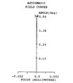
ここで、対物レンズとして、上記表1および図3に示す対物レンズ6を用いた場合の球面収差(LONGITUDINAL SPHERICAL ABER )を図4に、非点収差(ASTIGMATIC FIELD CURVES )を図5に示す。また、X軸方向とは、光透過層11と平行な面において、偏光ビームスプリッター4と検出系集光レンズ8とを結ぶ方向に平行な方向である。Y方向とは、光透過層11と平行な面において、X方向と垂直をなす方向である。
【0079】
図4に示すように、対物レンズ6を用いることにより、球面収差を抑制することができることがわかる。また、図5に示すように、対物レンズ6を用いることにより、非点収差を抑制することができることがわかる。
【0080】
また、対物レンズ6へのレーザビームの入射角が0.5度の場合の横収差を示すグラフを図6(a)(b)に、対物レンズ6へのレーザビームの入射角が0度の場合の横収差を示すグラフを図7(a)(b)に示す。
【0081】
図6・図7に示すように、対物レンズ6を用いることにより、X軸方向とY軸方向との収差が少なく、コマ収差も抑制することができる。
【0082】
次に、対物レンズ6の製造誤差の補正方法について説明する。
【0083】
対物レンズ6を製造する際、モールド時の金型の位置合わせ精度、対物レンズ6の材料であるプリフォームの重量や体積の精度、金型の加工精度などを考慮すると、対物レンズ6の両面の傾きは±1〜2分ばらつく。また、対物レンズ6の両面の中心ずれは±5μm程度である。この対物レンズ6の両面の傾きや中心ずれにより、コマ収差が発生する。
【0084】
一方、光ピックアップ装置においては、ディスク7における情報記録面12上でのビームスポットの収差が、波面のr.m.s値で0.07λ以下(Marechal Criteria )であれば、十分絞り込んだ良好なビームとなる。この許容収差を光学部品に配分すると、対物レンズ6においては、0.03λ程度の収差に抑える必要がある。ここで、λは、波長である。
【0085】
対物レンズ6の両面、即ち、第1面S1と第2面S2との傾きや中心ずれにより発生したコマ収差は、例えば、対物レンズ6の傾き(対物レンズチルト)やディスク7の傾き(ディスクチルト)を調整することにより補正することができる。
【0086】
例えば、対物レンズ6における設計値に対する両面の傾き誤差が−10分〜10分の場合のコマ収差を、補正なしの場合、ディスク7の傾きを調整することにより補正した場合、および、対物レンズ6の傾きとディスク7の傾きとを共に調整することにより補正した場合について図10に示す。
【0087】
図10に示すように、対物レンズ6における設計値に対する両面の傾き誤差が±2分程度発生した場合でも、上記のような補正をすることにより、コマ収差を0.03λ程度とすることができる。このように、容易にコマ収差を補正することができ、また、このような対物レンズ6は容易に製造することができる。
【0088】
また、対物レンズ6における設計値に対する両面の中心ずれ誤差が−20μm〜20μmの場合のコマ収差を、補正なしの場合、対物レンズ6の傾きを調整することにより補正した場合、および、対物レンズ6の傾きとディスク7の傾きと共に調整することにより補正した場合について図11に示す。
【0089】
図11に示すように、対物レンズ6における設計値に対する両面の中心ずれ誤差が±5μm程度発生した場合でも、上記のように補正をすることにより、コマ収差を0.03λ程度とすることができる。このように、容易にコマ収差を補正することができ、また、このような対物レンズ6は容易に製造することができる。
【0090】
このように、対物レンズ6の製造誤差が大きく、コマ収差が発生しても、対物レンズ6の傾きやディスク7の傾きを調整することにより補正することができ、コマ収差を小さくすることができる。このような調整は、対物レンズ6を光ピックアップ装置に搭載する際、あるいは、光ピックアップ装置を記録再生装置に搭載する際に行えばよい。
【0091】
このとき、再生信号のジッタ、エンベロープ、別途収差を検出する手段、または、対物レンズ6により、絞り込まれたレーザビームの形状や収差を観察・検出しながら、最適な対物レンズ6の傾きやディスク7の傾きに調整して固定してもかまわない。
【0092】
また、対物レンズ6において、その厚さにばらつきがあると、球面収差が発生する。このような球面収差は、半導体レーザ1とコリメータレンズ2との間の距離を図示しない補正手段により調節することにより、補正することができる。
【0093】
なお、球面収差については、凸レンズを2枚、あるいは、凸レンズと凹レンズとを組み合わせた、いわゆるビームエキスパンダーなどの光学系を別途搭載することにより補正してもかまわない。
【0094】
また、対物レンズの構成は、上記表1および図3に示したものに限られるものではなく、以下に示す表2および図12に示される対物レンズ20としてもかまわない。対物レンズ20の開口数NAや焦点距離など、表2に示す条件以外は、表1および図3に示す対物レンズ6と同様である。
【0095】
【表2】
ここで、対物レンズとして、上記表2および図12に示す対物レンズ20を用いた場合の球面収差を図13に、非点収差を図14に示す。
【0097】
図13に示すように、対物レンズ20を用いることにより、球面収差を抑制することができる。また、図14に示すように、対物レンズ20を用いることにより、非点収差を抑制することができる。
【0098】
また、対物レンズ20へのレーザビームの入射角が0.5度の場合の横収差を示すグラフを図15(a)(b)に、対物レンズ20へのレーザビームの入射角が0度の場合の横収差を示すグラフを図16(a)(b)に示す。
【0099】
図15・図16に示すように、対物レンズ20を用いることにより、X軸方向とY軸方向との収差が少なく、コマ収差も抑制することができる。
【0100】
対物レンズの構成は、以下に示す表3および図17に示される対物レンズ30としてもかまわない。対物レンズ30の開口数NAや焦点距離など、表3に示す条件以外は、表1および図3に示す対物レンズ6と同様である。
【0101】
【表3】
ここで、対物レンズとして、上記表3および図17に示す対物レンズ30を用いた場合の球面収差を図18に、非点収差を図19に示す。
【0103】
図18に示すように、対物レンズ30を用いることにより、球面収差を抑制することができる。また、図19に示すように、対物レンズ30を用いることにより、非点収差を抑制することができる。
【0104】
また、対物レンズ30へのレーザビームの入射角が0.5度の場合の横収差を示すグラフを図20(a)(b)に、対物レンズ30へのレーザビームの入射角が0度の場合の横収差を示すグラフを図21(a)(b)に示す。
【0105】
図20・図21に示すように、対物レンズ30を用いることにより、X軸方向とY軸方向との収差が少なく、コマ収差も抑制することができる。
【0106】
対物レンズの構成は、以下に示す表4および図22に示される対物レンズ40としてもかまわない。対物レンズ40の開口数NAや焦点距離など、表4に示す条件以外は、表1および図3に示す対物レンズ6と同様である。
【0107】
【表4】
ここで、対物レンズとして、上記表4および図22に示す対物レンズ40を用いた場合の球面収差を図23に、非点収差を図24に示す。
【0109】
図23に示すように、対物レンズ40を用いることにより、球面収差を抑制することができる。また、図24に示すように、対物レンズ40を用いることにより、非点収差を抑制することができる。
【0110】
また、対物レンズ40へのレーザビームの入射角が0.5度の場合の横収差を示すグラフを図25(a)(b)に、対物レンズ40へのレーザビームの入射角が0度の場合の横収差を示すグラフを図26(a)(b)に示す。
【0111】
図25・図26に示すように、対物レンズ40を用いることにより、X軸方向とY軸方向との収差が少なく、コマ収差も抑制することができる。
【0112】
対物レンズの構成は、以下に示す表5および図27に示される対物レンズ50としてもかまわない。対物レンズ50の開口数NAや焦点距離など、表5に示す条件以外は、表1および図3に示す対物レンズ6と同様である。
【0113】
【表5】
ここで、対物レンズとして、上記表5および図27に示す対物レンズ50を用いた場合の球面収差を図28に、非点収差を図29に示す。
【0115】
図28に示すように、対物レンズ50を用いることにより、球面収差を抑制することができる。また、図29に示すように、対物レンズ50を用いることにより、非点収差を抑制することができる。
【0116】
また、対物レンズ50へのレーザビームの入射角が0.5度の場合の横収差を示すグラフを図30(a)(b)に、対物レンズ50へのレーザビームの入射角が0度の場合の横収差を示すグラフを図31(a)(b)に示す。
【0117】
図30・図31に示すように、対物レンズ50を用いることにより、X軸方向とY軸方向との収差が少なく、コマ収差も抑制することができる。
【0118】
対物レンズの構成は、以下に示す表6および図32に示される対物レンズ60としてもかまわない。対物レンズ60の開口数NAや焦点距離など、表6に示す条件以外は、表1および図3に示す対物レンズ6と同様である。
【0119】
【表6】
ここで、対物レンズとして、上記表6および図32に示す対物レンズ60を用いた場合の球面収差を図33に、非点収差を図34に示す。
【0121】
図33に示すように、対物レンズ60を用いることにより、球面収差を抑制することができる。また、図34に示すように、対物レンズ60を用いることにより、非点収差を抑制することができる。
【0122】
また、対物レンズ60へのレーザビームの入射角が0.5度の場合の横収差を示すグラフを図35(a)(b)に、対物レンズ40へのレーザビームの入射角が0度の場合の横収差を示すグラフを図36(a)(b)に示す。
【0123】
図35・図36に示すように、対物レンズ60を用いることにより、X軸方向とY軸方向との収差が少なく、コマ収差も抑制することができる。
【0124】
このように、対物レンズ6・20・30・40・50・60は、単レンズを用いている。このため、2群レンズのように煩雑なレンズ調整を必要とせず、また、樹脂なども使用しないため信頼性が高い。また、鏡筒などを必要としないため、軽量で高速記録・再生が可能な対物レンズを提供することができる。さらに、回折素子を必要としないので、光の利用効率が高く、製造が容易で、かつ、小型化を図ることができる。
【0125】
また、対物レンズ6・20・30・40・50・60は、開口数NAが0.75以上であるため、ビームスポットを小さくすることができ、ディスク7における高記録密度化を図ることができる。
【0126】
さらに、対物レンズ6・20・30・40・50・60の材料となるガラスの、使用波長のうちの少なくとも1つにおける屈折率をnとし、d線におけるアッベ数をvとすると、nおよびvは、次式(7)
1.75<n、かつ、35<v …(7)
で表される。
【0127】
光の波長によってガラスの屈折率が異なることにより、色収差が生る。この色収差により、像の位置や大きさが波長によって異なることとなる。
【0128】
しかしながら、35<vとすることにより、色収差を小さくすることができ、僅かな半導体レーザ1の波長変動により像点が移動してビームスポットがぼけることを防止することができる。
【0129】
また、1.75<nとすることにより、第1面S1の曲率を小さくすることができ、容易に対物レンズを製造することができる。
【0130】
【発明の効果】
以上のように、本発明の対物レンズは、開口数が0.75以上の対物レンズであって、該対物レンズは両面が非球面の単玉対物レンズであり、かつ、光が入射する側の面が凸面であるメニスカス型レンズであり、使用波長の少なくとも1つにおける屈折率をnとし、d線におけるアッベ数をvとすると、1.75<n、かつ、35<vを満足する材料からなり、上記対物レンズの焦点距離をfとし、該対物レンズの第1面の焦点距離をf1とすると、0.5<f/f1<0.6を満足すると共に、上記対物レンズの開口数をNAとし、該対物レンズの有効径をDとし、該対物レンズの中心厚さをtとすると、0.8<t/(NA・D)<1.0を満足する構成である。
【0131】
これにより、例えば、回折素子などは必要としない。このため、対物レンズを透過する光(レーザビーム)の利用効率を高くすることができる。また、対物レンズの製造を容易にすることができ、さらに対物レンズの小型化を図ることができる。また、対物レンズの開口数が0.75以上であるため、例えば、記録媒体に照射するビームスポットを小さくすることができ、記録媒体における高記録密度化を図ることができる。また、光が入射する側の面が凸面であるメニスカス型レンズであるので、コマ収差および球面収差を小さくすることができる。
【0132】
また、35<vとすることにより、色収差を小さくすることができ、僅かな波長変動によって、像点が移動し、ビームスポットがぼけることを防止することができる。さらに、1.75<nとすることにより、対物レンズの第1面の曲率を小さくすることができ、容易に対物レンズを製造することができる。
【0133】
また、第2面によるレーザビームの屈折は小さくてよく、第2面の曲率を小さくすることができる。従って、第2面による球面収差を小さくすることができる。また、作動距離WD(ワーキングディスタンス)を長くすることができるといった効果を奏する。
【0134】
また、良好な軸外特性を得ることができる。また、対物レンズの体積や重量を小さくすることができる。従って、光ピックアップ装置における対物レンズの高速駆動を図ることができ、また、形状不良を起こすことなく、対物レンズを製造することができるといった効果を奏する。
【0135】
以上のように、本発明の光ピックアップ装置は、光源と上記記載の対物レンズとを備え、該対物レンズを用いて、光源から出射された光を記録媒体に照射することにより、該記録媒体に情報を記録または再生する構成である。
【0136】
これにより、対物レンズを透過する光(レーザビーム)の利用効率低下を伴うことなく、色収差や球面収差などが小さく、レーザビームを記録媒体に精度良く集光することができる光ピックアップ装置を提供することができるといった効果を奏する。
【0137】
以上のように、本発明の光ピックアップ装置は、光源と上記対物レンズとの間に、光源からの光を平行光束にするコリメータレンズと、球面収差をコリメータレンズと光源との距離を調整することにより補正する補正手段とを備えている構成である。
【0138】
これにより、色収差や球面収差などが小さく、また、それらの収差を容易に補正することができる光ピックアップ装置を提供することができるといった効果を奏する。
【0139】
以上のように、本発明の対物レンズの製造誤差の補正方法は、上記記載の光ピックアップ装置に用いられる対物レンズを製造する際に発生する製造誤差を、光ピックアップ装置に対する対物レンズの傾きを調整することにより補正する構成である。
【0140】
これにより、対物レンズの製造誤差によるコマ収差を光ピックアップ装置に対する対物レンズの傾きを調整することにより補正するので、収差を小さくすることができ、また、その収差は容易に補正することができるといった効果を奏する。
【0141】
以上のように、本発明の対物レンズの製造誤差の補正方法は、上記記載の光ピックアップ装置に用いられる対物レンズを製造する際に発生する製造誤差を、光ピックアップ装置に対する記録媒体の傾きを調整することにより補正する構成である。
【0142】
これにより、対物レンズの製造誤差によるコマ収差を、光ピックアップ装置に対する記録媒体の傾きを調整することにより補正するので、収差を小さくすることができ、また、その収差は容易に補正することができるといった効果を奏する。
【図面の簡単な説明】
【図1】 本発明の実施の一形態に係る光ピックアップ装置の概略の構成を示す説明図である。
【図2】 ディスクの構成を示す説明図である。
【図3】 上記光ピックアップ装置に用いられている対物レンズおよび絞りの構成を示す説明図である。
【図4】 図3に示す対物レンズの球面収差を示すグラフである。
【図5】 図3に示す対物レンズの非点収差を示すグラフである。
【図6】 (a)は、図3に示す対物レンズへのレーザビームの入射角が0.5度の場合のY軸方向の横収差を示すグラフであり、(b)は、図3に示す対物レンズへのレーザビームの入射角が0.5度の場合のX軸方向の横収差を示すグラフである。
【図7】 (a)は、図3に示す対物レンズへのレーザビームの入射角が0度の場合のY軸方向の横収差を示すグラフであり、(b)は、図3に示す対物レンズへのレーザビームの入射角が0度の場合のX軸方向の横収差を示すグラフである。
【図8】 対物レンズの第1面における、中心軸からの距離(mm)と近軸曲率からのずれを示すグラフである。
【図9】 対物レンズの第2面における、中心軸からの距離と近軸曲率からのずれを示すグラフである。
【図10】 設計値に対する対物レンズ両面の傾き誤差が−10分〜10分の場合のコマ収差を示すグラフである。
【図11】 設計値に対する対物レンズ両面の中心ずれ誤差が−20μm〜20μmの場合のコマ収差を示すグラフである。
【図12】 対物レンズの他の構成を示す説明図である。
【図13】 図12に示す対物レンズの球面収差を示すグラフである。
【図14】 図12に示す対物レンズの非点収差を示すグラフである。
【図15】 (a)は、図12に示す対物レンズへのレーザビームの入射角が0.5度の場合のY軸方向の横収差を示すグラフであり、(b)は、図12に示す対物レンズへのレーザビームの入射角が0.5度の場合のX軸方向の横収差を示すグラフである。
【図16】 (a)は、図12に示す対物レンズへのレーザビームの入射角が0度の場合のY軸方向の横収差を示すグラフであり、(b)は、図12に示す対物レンズへのレーザビームの入射角が0度の場合のX軸方向の横収差を示すグラフである。
【図17】 対物レンズのさらに他の構成を示す説明図である。
【図18】 図17に示す対物レンズの球面収差を示すグラフである。
【図19】 図17に示す対物レンズの非点収差を示すグラフである。
【図20】 (a)は、図17に示す対物レンズへのレーザビームの入射角が0.5度の場合のY軸方向の横収差を示すグラフであり、(b)は、図17に示す対物レンズへのレーザビームの入射角が0.5度の場合のX軸方向の横収差を示すグラフである。
【図21】 (a)は、図17に示す対物レンズへのレーザビームの入射角が0度の場合のY軸方向の横収差を示すグラフであり、(b)は、図17に示す対物レンズへのレーザビームの入射角が0度の場合のX軸方向の横収差を示すグラフである。
【図22】 対物レンズのさらに他の構成を示す説明図である。
【図23】 図22に示す対物レンズの球面収差を示すグラフである。
【図24】 図22に示す対物レンズの非点収差を示すグラフである。
【図25】 (a)は、図22に示す対物レンズへのレーザビームの入射角が0.5度の場合のY軸方向の横収差を示すグラフであり、(b)は、図22に示す対物レンズへのレーザビームの入射角が0.5度の場合のX軸方向の横収差を示すグラフである。
【図26】 (a)は、図22に示す対物レンズへのレーザビームの入射角が0度の場合のY軸方向の横収差を示すグラフであり、(b)は、図22に示す対物レンズへのレーザビームの入射角が0度の場合のX軸方向の横収差を示すグラフである。
【図27】 対物レンズのさらに他の構成を示す説明図である。
【図28】 図27に示す対物レンズの球面収差を示すグラフである。
【図29】 図27に示す対物レンズの非点収差を示すグラフである。
【図30】 (a)は、図27に示す対物レンズへのレーザビームの入射角が0.5度の場合のY軸方向の横収差を示すグラフであり、(b)は、図27に示す対物レンズへのレーザビームの入射角が0.5度の場合のX軸方向の横収差を示すグラフである。
【図31】 (a)は、図27に示す対物レンズへのレーザビームの入射角が0度の場合のY軸方向の横収差を示すグラフであり、(b)は、図27に示す対物レンズへのレーザビームの入射角が0度の場合のX軸方向の横収差を示すグラフである。
【図32】 対物レンズのさらに他の構成を示す説明図である。
【図33】 図32に示す対物レンズの球面収差を示すグラフである。
【図34】 図32に示す対物レンズの非点収差を示すグラフである。
【図35】 (a)は、図32に示す対物レンズへのレーザビームの入射角が0.5度の場合のY軸方向の横収差を示すグラフであり、(b)は、図32に示す対物レンズへのレーザビームの入射角が0.5度の場合のX軸方向の横収差を示すグラフである。
【図36】 (a)は、図32に示す対物レンズへのレーザビームの入射角が0度の場合のY軸方向の横収差を示すグラフであり、(b)は、図32に示す対物レンズへのレーザビームの入射角が0度の場合のX軸方向の横収差を示すグラフである。
【図37】 従来の光ピックアップ装置の要部の構成を示す説明図である。
【符号の説明】
1 半導体レーザ(光源)
2 コリメータレンズ
3 整形プリズム
4 偏光ビームスプリッター
5 1/4波長板
6 対物レンズ
7 ディスク(記録媒体)
8 検出系集光レンズ
9 光検出器
10 レンズホルダー
11 光透過層
12 情報記録面
14 絞り
20 対物レンズ
30 対物レンズ
40 対物レンズ
50 対物レンズ
60 対物レンズ[0001]
BACKGROUND OF THE INVENTION
The present invention relates to an objective lens that records and reproduces information on an optical information recording medium, and more particularly, to an objective lens with less aberration, a method for correcting manufacturing errors thereof, and an optical pickup device using the objective lens.
[0002]
[Prior art]
The technology using light has many features such as high speed, high frequency, spatial information processing, and phase processing. For this reason, it has been researched and developed in a wide range of fields such as communication, measurement, and processing, and put into practical use.
[0003]
Among these techniques, a high-precision objective lens is used to narrow down a light beam emitted from a light source and applied to a recording medium. In recent years, there has been a great demand for image recording devices that use light, and techniques for increasing the capacity have become very important. In order to increase the capacity of optical information recording, it is necessary to reduce the diameter of the beam spot, that is, to sufficiently narrow the beam spot by the objective lens, in addition to increasing the recording density of the recording medium. By reducing the beam spot in this way, more information can be recorded.
[0004]
The beam spot diameter is proportional to the wavelength of the light source to be used, and is inversely proportional to the numerical aperture NA (Numerical Aperture) of the objective lens. Therefore, in order to reduce the diameter of the beam spot, it is necessary to shorten the wavelength of the light source used or increase the numerical aperture NA of the objective lens to increase the numerical aperture.
[0005]
Regarding the wavelength of light, blue laser diodes and blue or green SHG lasers are being developed in recent years, and the wavelength is being shortened.
[0006]
On the other hand, regarding the numerical aperture NA of the objective lens, for example, CD (Compact Disc) is NA = 0.45, and DVD (Digital Versatile Disc) is NA = 0.0.6. Thus, the DVD has a higher numerical aperture than the CD, and has achieved a higher density of information that can be recorded.
[0007]
Japanese Patent Laid-Open No. 10-123410 discloses an optical pickup device that aims to further increase the numerical aperture of an objective lens by using two lenses in two groups. In this optical pickup device, an objective lens is composed of two lenses in two groups integrated through a lens barrel or the like. Thereby, the numerical aperture of the objective lens can be set to NA = 0.85, and the numerical aperture can be increased.
[0008]
However, this optical pickup device is configured by two lenses in two groups in which an objective lens is integrated through a lens barrel or the like. Accordingly, when these lenses are integrated, the distance between the lenses, the inclination with respect to the optical axis, the center deviation, and the like must be accurately positioned. For this reason, it is necessary to adjust the position while actually observing the narrowed-down state of the beam spot and the generated aberration at the time of positioning, and these positioning steps become complicated.
[0009]
In addition, resin is required to fix two lenses in two groups. This resin does not have sufficient heat resistance and moisture resistance and changes over time. As described above, the resin may cause a characteristic change, and is not reliable.
[0010]
Furthermore, the weight of the two lenses in two groups increases when including a lens barrel. In general, focus control and tracking control are performed by moving an objective lens in a direction parallel to or perpendicular to an optical axis by an actuator (drive device). At this time, if the weight of the objective lens is large, the objective lens cannot be driven at a high speed, resulting in a delay in information recording / reproducing speed.
[0011]
On the other hand, an optical pickup device that uses a single lens as an objective lens to increase the numerical aperture is described in Japanese Patent Laid-Open No. 9-311271. As shown in FIG. 37, the optical pickup device includes an objective lens in which a
[0012]
As described above, since a single lens is used for the objective lens of the optical pickup device shown in FIG. 37, there is no need for a positioning step or a resin for fixing the lens.
[0013]
[Problems to be solved by the invention]
However, the objective lens shown in FIG. 37 uses a combination of the
[0014]
The present invention has been made in view of the above-described conventional problems, and an object of the present invention is to reduce the size of the aberration and reduce the aberration without reducing the light utilization efficiency. It is an object of the present invention to provide an objective lens that can easily correct the above, a manufacturing error correction method thereof, and an optical pickup device using the objective lens.
[0015]
[Means for Solving the Problems]
In order to solve the above problems, the objective lens of the present invention is an objective lens having a numerical aperture of 0.75 or more, and the objective lens is a single objective lens having both aspheric surfaces.And a meniscus lens having a convex surface on the light incident side, where n is the refractive index at least one of the wavelengths used, and v is the Abbe number in the d-line,
1.75 <n and 35 <v
Made of material that satisfies the aboveIf the focal length of the objective lens is f and the focal length of the first surface of the objective lens is f1,
0.5 <f / f1 <0.6
And the numerical aperture of the objective lens is NA, the effective diameter of the objective lens is D, and the center thickness of the objective lens is t,
0.8 <t / (NA · D) <1.0
It is characterized by satisfying.
[0016]
According to said structure, the single objective lens is used as an objective lens, for example, a diffraction element etc. are not required. For this reason, the utilization efficiency of the light (laser beam) which permeate | transmits an objective lens can be made high. In addition, the objective lens can be easily manufactured, and the objective lens can be miniaturized.
[0017]
Further, since the numerical aperture of the objective lens is 0.75 or more, for example, the beam spot irradiated on the recording medium can be reduced, and the recording density of the recording medium can be increased.
[0018]
In addition, since the surface on which light is incident is a meniscus lens having a convex surface, coma and spherical aberration can be reduced.
[0019]
In general, chromatic aberration is caused by a difference in refractive index in the material of the objective lens depending on the wavelength of light, whereby the position and size of the image differ depending on the wavelength.
[0020]
However, according to the above configuration, chromatic aberration can be reduced by setting 35 <v, and it is possible to prevent the image spot from moving and the beam spot from being blurred due to slight wavelength fluctuations.
[0021]
Further, when 1.75 <n, the curvature of the first surface of the objective lens can be reduced, and the objective lens can be easily manufactured.
[0022]
In general, in an objective lens, spherical aberration occurs depending on the configuration of the objective lens, such as the curvature and shape of the aspherical vertex. Due to the occurrence of this spherical aberration, it becomes difficult to accurately focus the laser beam on the recording medium.
[0023]
However, according to the above configuration, by setting 0.5 <f / f1, the focal length of the first surface can be reduced, that is, the curvature can be increased. Thereby, the refraction of the laser beam by the second surface may be small, and the curvature of the second surface can be reduced. Therefore, the spherical aberration due to the second surface can be reduced.
[0024]
Further, by setting f / f1 <0.6, the focal length of the first surface can be increased, that is, the curvature can be decreased. Thereby, working distance WD (working distance) can be lengthened.
[0025]
According to said structure, a favorable off-axis characteristic can be acquired by setting it as 0.8 <t / (NA * D).
[0026]
By setting t / (NA · D) <1.0, the volume and weight of the objective lens can be reduced. Thereby, the objective lens in the optical pickup device can be driven at high speed.
[0027]
For example, when t / (NA · D) is 1.0 or more, for example, if the objective lens is made of glass, when manufacturing the objective lens, a large-volume preform (spherical shape before molding) Glass material) is required. At this time, if a preform having a normal size is used, the curvature radius of the preform is larger than the curvature radius of the first surface of the objective lens. There is a space between the lens and the glass. Since the gas in this space does not escape, the formed objective lens is prone to shape defects.
[0028]
However, by setting t / (NA · D) <1.0, the objective lens can be manufactured without causing a shape defect.
[0029]
An optical pickup device of the present invention includes a light source and the objective lens described above, and records or reproduces information on the recording medium by irradiating the recording medium with light emitted from the light source using the objective lens. It is characterized by that.
[0030]
According to the above configuration, an optical pickup capable of accurately condensing a laser beam on a recording medium with little chromatic aberration, spherical aberration, and the like without causing a decrease in utilization efficiency of light (laser beam) transmitted through the objective lens. An apparatus can be provided.
[0031]
The optical pickup device includes a collimator lens that converts light from the light source into a parallel light beam between the light source and the objective lens, and correction means that corrects spherical aberration by adjusting the distance between the collimator lens and the light source. Are preferably provided.
[0032]
According to the above configuration, it is possible to provide an optical pickup device that has small chromatic aberration, spherical aberration, and the like and that can easily correct these aberrations.
[0033]
According to the objective lens manufacturing error correction method of the present invention, a manufacturing error generated when manufacturing the objective lens used in the optical pickup device described above is corrected by adjusting the tilt of the objective lens with respect to the optical pickup device. It is characterized by that.
[0034]
In general, when manufacturing the objective lens, the tilt of both sides of the objective lens is taken into consideration when considering the positioning accuracy of the mold during molding, the accuracy of the weight and volume of the preform that is the material of the objective lens, the processing accuracy of the mold, etc. And manufacturing errors such as misalignment of both sides of the objective lens occur. This manufacturing error causes coma.
[0035]
However, according to the above configuration, the coma due to the manufacturing error is corrected by adjusting the tilt of the objective lens with respect to the optical pickup device, so that the aberration can be reduced and the aberration can be easily corrected. be able to.
[0036]
According to the objective lens manufacturing error correction method of the present invention, a manufacturing error that occurs when manufacturing the objective lens used in the optical pickup device described above is corrected by adjusting the tilt of the recording medium with respect to the optical pickup device. It is characterized by that.
[0037]
According to the above configuration, the coma due to the manufacturing error is corrected by adjusting the tilt of the recording medium with respect to the optical pickup device, so that the aberration can be reduced and the aberration can be easily corrected. it can.
[0038]
DETAILED DESCRIPTION OF THE INVENTION
An embodiment of the present invention will be described below with reference to FIGS.
[0039]
FIG. 1 is an explanatory diagram showing the configuration of the optical pickup device. As shown in FIG. 1, the optical pickup device according to the present embodiment includes a
[0040]
As shown in FIG. 2, the
[0041]
The
[0042]
The
[0043]
The
[0044]
The shaping
[0045]
The polarization beam splitter 4 is a cube obtained by applying a polarizing film to one of the inclined surfaces of two right-angle prisms and bonding them. The polarization beam splitter 4 transmits a light wave having a polarization direction parallel to the incident surface and reflects a light wave having a polarization direction perpendicular to the incident surface.
[0046]
The
[0047]
The
[0048]
The objective lens 6 is fixed to the
[0049]
The detection
[0050]
The
[0051]
The laser beam emitted from the
[0052]
This laser beam passes through the polarization beam splitter 4 and enters the quarter-
[0053]
The laser beam condensed on the
[0054]
The laser beam reflected by the polarization beam splitter 4 is condensed by the detection
[0055]
Hereinafter, the objective lens 6 will be described.
[0056]
As shown in FIG. 3, the objective lens 6 is a double-sided aspheric single lens (single objective lens) made of glass, and its numerical aperture NA is 0.85. Here, the aspheric shape is expressed by the following equation (1).
Z = (1 / r) y2 / [1+ {1- (1 + K) (1 / r)2y2 }1/2 ] + Ay4 + By6 + Cy8 + Dy10+ Ey12+ Fy14+ Gy16+ Hy18+ Jy20 ... (1)
It is represented by
[0057]
Here, Z is the distance from the tangent plane of the surface vertex, y is the distance from the optical axis, 1 / r is the curvature of the aspherical vertex (r is the radius of curvature), K is the conic constant, and A is y4Term aspheric coefficient, B is y6 Term aspheric coefficient, C is y8 Term aspheric coefficient, D is y10Term aspheric coefficient, E is y12Term aspheric coefficient, F is y14Term aspheric coefficient, G is y16Term aspheric coefficient, H is y18Term aspheric coefficient, J is y20Is the aspheric coefficient of the term.
[0058]
The objective lens 6 is a so-called infinite lens in which the
[0059]
Table 1 shows the distance (mm) between the objective lens 6 and the
[0060]
[Table 1]
The objective lens 6 is designed so as to be substantially free of aberration when the thickness of the
[0062]
Here, the refractive index for the spectral line of the d-line (wavelength 587.6 nm) is nd, the refractive index for the spectral line of the F-line (wavelength 486.1 nm) is nF, and the spectral line of the C-line (wavelength 656.3 nm). Where the refractive index for n is nC, the Abbe number v at the d-line is given by the following equation (2):
v = (nd-1) / (nF-nC) (2)
It is represented by The effective diameter of the objective lens 6 is a diameter within a range in which the laser beam can enter the objective lens 6.
[0063]
Further, the objective lens 6 is given by the following formula (3), where f is the focal length and f1 is the focal length of the first surface S1.
0.5 <f / f1 <0.6 (3)
It is represented by
[0064]
In general, in an objective lens, spherical aberration occurs due to the configuration of the objective lens such as the curvature and shape of the aspherical vertex. Further, when a recording medium such as a disk is tilted, coma aberration occurs in the laser beam. The laser beam forms an image at different positions in the X-axis direction and the Y-axis direction, and this phenomenon is called astigmatism. Generation of these aberrations makes it difficult to focus the laser beam on the disk with high accuracy.
[0065]
However, as shown in the above equation (3), by setting 0.5 <f / f1, the focal length of the first surface S1 can be reduced, that is, the curvature can be increased. Thereby, the refraction of the laser beam by the second surface S2 may be small, and the curvature of the second surface S2 can be reduced. Therefore, the spherical aberration due to the second surface S2 can be reduced.
[0066]
Further, by setting f / f1 <0.6, the focal length of the first surface S1 can be increased, that is, the curvature can be decreased. Thereby, working distance WD (working distance) can be lengthened.
[0067]
As shown in FIG. 3, the objective lens 6 is a meniscus lens in which the first surface S1, that is, the surface on which the laser beam is incident is a convex surface. Therefore, good off-axis characteristics can be obtained, and coma and spherical aberration can be reduced.
[0068]
The objective lens 6 has the following numerical expression (4), where NA is the numerical aperture, D is the effective diameter, and t is the thickness at the center.
0.8 <t / (NA · D) <1.0 (4)
Satisfied. By setting 0.8 <t / (NA · D), good off-axis characteristics can be obtained.
[0069]
In general, when the numerical aperture NA and the effective diameter D of the objective lens 6 are determined, the relationship between the curvatures of the first surface S1 and the second surface S2 in the objective lens 6 is substantially determined. Thereby, the greatest factor that determines the weight (volume) of the objective lens 6 is the thickness of the objective lens 6. That is, when the objective lens 6 is thick, the weight increases, and when the objective lens 6 is thin, the weight decreases.
[0070]
Therefore, by setting t / (NA · D) <1.0, the volume and weight of the objective lens 6 can be reduced. Thereby, the objective lens 6 in the optical pickup device can be driven at high speed. In addition, when t / (NA · D) is 1.0 or more, a large volume of preform (spherical glass material before molding) is required when the objective lens 6 is manufactured. At this time, if a preform having a normal size is used, the radius of curvature of the preform is larger than the radius of curvature of the first surface S1 of the objective lens 6, so that the central portion of the first surface of the mold is used. And a glass which becomes the objective lens 6. Accordingly, since the gas in this space cannot escape, the formed objective lens 6 is liable to cause a shape defect. However, by setting t / (NA · D) <1.0, the objective lens 6 can be manufactured without causing a shape defect.
[0071]
Both the first surface S1 and the second surface S2 of the objective lens 6 are such that the objective lens 6 is monotonously thicker toward the center, that is, the spherical surface represented by the paraxial radius of curvature, as the distance from the surface vertex increases. It has a shape. FIG. 8 shows the deviation of the first surface S1 from the spherical surface represented by the paraxial radius of curvature, and FIG. 9 shows the deviation of the second surface S2 from the spherical surface represented by the paraxial radius of curvature.
[0072]
Thereby, it is possible to relieve the steep surface inclination of the objective lens 6 due to the high numerical aperture NA of the objective lens 6. Accordingly, the mold can be easily manufactured. In addition, spherical aberration can be reduced.
[0073]
The numerical aperture of the objective lens 6 is NA, and the tangent of the objective lens surface at the incident position of the light having the highest incident height among the effective diameters of the first surface S1 (the surface on the light incident side of the objective lens 6). If the angle formed by the perpendicular to the optical axis of the incident light is θ (degrees), the objective lens 6 can be expressed by the following equation (5).
60 · NA <θ (5)
Satisfied. 3, the tangent to the surface of the objective lens 6 at one point on the outer periphery of the light beam of the laser beam irradiated to the objective lens 6 by being limited by the
[0074]
In general, in order to suppress coma, it is necessary to increase the angle θ or increase the thickness of the objective lens 6. By increasing the angle θ, the curve of the first surface S1 of the objective lens 6 becomes steep. Thereby, even if the laser beam is incident on the objective lens 6 at an angle, coma aberration can be suppressed.
[0075]
Therefore, since the angle θ can be increased by satisfying the above formula (5), it is possible to obtain good off-axis characteristics even in a thin objective lens.
[0076]
When the numerical aperture of the objective lens 6 is NA, the effective diameter is D, and the working distance is WD, the objective lens 6 is expressed by the following formula (6).
D / (20 ・ NA5 ) <WD (6)
Satisfied.
[0077]
Thereby, the working distance WD can be lengthened. Therefore, the distance between the objective lens 6 and the
[0078]
Here, FIG. 4 shows spherical aberration (LONGITUDINAL SPHERICAL ABER) when the objective lens 6 shown in Table 1 and FIG. 3 is used as the objective lens, and FIG. 5 shows astigmatism (ASTIGMATIC FIELD CURVES). The X-axis direction is a direction parallel to the direction connecting the polarization beam splitter 4 and the detection
[0079]
As shown in FIG. 4, it can be seen that spherical aberration can be suppressed by using the objective lens 6. Further, as shown in FIG. 5, it can be seen that astigmatism can be suppressed by using the objective lens 6.
[0080]
6A and 6B are graphs showing transverse aberration when the incident angle of the laser beam to the objective lens 6 is 0.5 degrees, and FIG. The graph which shows the lateral aberration in the case is shown to Fig.7 (a) (b).
[0081]
As shown in FIGS. 6 and 7, by using the objective lens 6, the aberration in the X-axis direction and the Y-axis direction is small, and coma can be suppressed.
[0082]
Next, a method for correcting the manufacturing error of the objective lens 6 will be described.
[0083]
When manufacturing the objective lens 6, considering the positioning accuracy of the mold at the time of molding, the weight and volume accuracy of the preform as the material of the objective lens 6, the processing accuracy of the mold, and the like, The slope varies ± 1 to 2 minutes. Further, the center deviation of both surfaces of the objective lens 6 is about ± 5 μm. A coma aberration occurs due to the tilt and center deviation of both surfaces of the objective lens 6.
[0084]
On the other hand, in the optical pickup device, the aberration of the beam spot on the
[0085]
For example, coma aberration caused by the tilt or center deviation between both surfaces of the objective lens 6, that is, the first surface S1 and the second surface S2, may be, for example, the tilt of the objective lens 6 (objective lens tilt) or the tilt of the disc 7 (disc tilt). ) Can be corrected.
[0086]
For example, coma aberration when the tilt error of both surfaces with respect to the design value of the objective lens 6 is −10 to 10 minutes is corrected without correction, by adjusting the tilt of the
[0087]
As shown in FIG. 10, even when a tilt error of both surfaces with respect to the design value of the objective lens 6 occurs about ± 2 minutes, the correction as described above can reduce the coma aberration to about 0.03λ. . Thus, coma can be easily corrected, and such an objective lens 6 can be easily manufactured.
[0088]
Further, coma aberration in the case where the center misalignment error of both surfaces with respect to the design value of the objective lens 6 is −20 μm to 20 μm is corrected by adjusting the inclination of the objective lens 6 when there is no correction, and the objective lens 6. FIG. 11 shows a case where correction is performed by adjusting the tilt of the
[0089]
As shown in FIG. 11, even when a center misalignment error of both surfaces with respect to the design value of the objective lens 6 occurs about ± 5 μm, the coma aberration can be set to about 0.03λ by correcting as described above. . Thus, coma can be easily corrected, and such an objective lens 6 can be easily manufactured.
[0090]
Thus, even if the manufacturing error of the objective lens 6 is large and coma aberration occurs, it can be corrected by adjusting the tilt of the objective lens 6 or the tilt of the
[0091]
At this time, the optimum tilt of the objective lens 6 and the
[0092]
Further, if the thickness of the objective lens 6 varies, spherical aberration occurs. Such spherical aberration can be corrected by adjusting the distance between the
[0093]
The spherical aberration may be corrected by separately mounting an optical system such as a so-called beam expander in which two convex lenses or a combination of a convex lens and a concave lens is used.
[0094]
The configuration of the objective lens is not limited to that shown in Table 1 and FIG. 3, but may be the
[0095]
[Table 2]
Here, FIG. 13 shows spherical aberration and FIG. 14 shows astigmatism when the
[0097]
As shown in FIG. 13, spherical aberration can be suppressed by using the
[0098]
FIGS. 15A and 15B are graphs showing transverse aberration when the incident angle of the laser beam to the
[0099]
As shown in FIGS. 15 and 16, by using the
[0100]
The configuration of the objective lens may be the
[0101]
[Table 3]
Here, FIG. 18 shows spherical aberration and FIG. 19 shows astigmatism when the
[0103]
As shown in FIG. 18, spherical aberration can be suppressed by using the
[0104]
20A and 20B are graphs showing transverse aberration when the incident angle of the laser beam to the
[0105]
As shown in FIGS. 20 and 21, by using the
[0106]
The configuration of the objective lens may be the
[0107]
[Table 4]
Here, FIG. 23 shows spherical aberration and FIG. 24 shows astigmatism when the
[0109]
As shown in FIG. 23, spherical aberration can be suppressed by using the
[0110]
Also, graphs showing lateral aberration when the incident angle of the laser beam to the
[0111]
As shown in FIGS. 25 and 26, by using the
[0112]
The configuration of the objective lens may be the
[0113]
[Table 5]
Here, FIG. 28 shows spherical aberration and FIG. 29 shows astigmatism when the
[0115]
As shown in FIG. 28, spherical aberration can be suppressed by using the
[0116]
30A and 30B are graphs showing transverse aberration when the incident angle of the laser beam to the
[0117]
As shown in FIGS. 30 and 31, by using the
[0118]
The configuration of the objective lens may be the
[0119]
[Table 6]
Here, FIG. 33 shows spherical aberration and FIG. 34 shows astigmatism when the
[0121]
As shown in FIG. 33, spherical aberration can be suppressed by using the
[0122]
Also, graphs showing transverse aberration when the incident angle of the laser beam to the
[0123]
As shown in FIGS. 35 and 36, by using the
[0124]
Thus, the
[0125]
Further, since the
[0126]
Further, n and v, where n is the refractive index of at least one of the wavelengths used and n is the Abbe number at the d-line of the glass used as the material of the
1.75 <n and 35 <v (7)
It is represented by
[0127]
Chromatic aberration occurs due to the difference in refractive index of glass depending on the wavelength of light. Due to this chromatic aberration, the position and size of the image vary depending on the wavelength.
[0128]
However, by setting 35 <v, the chromatic aberration can be reduced, and it is possible to prevent the beam spot from being blurred due to a slight change in the wavelength of the
[0129]
Further, by setting 1.75 <n, the curvature of the first surface S1 can be reduced, and the objective lens can be easily manufactured.
[0130]
【The invention's effect】
As described above, the objective lens of the present invention is an objective lens having a numerical aperture of 0.75 or more, and the objective lens is a single objective lens having both aspheric surfaces.And the surface on which light is incident is a convex meniscus lens, where n is the refractive index at at least one of the wavelengths used, and v is the Abbe number in the d-line, 1.75 <n, And made of a material satisfying 35 <v,When the focal length of the objective lens is f and the focal length of the first surface of the objective lens is f1, 0.5 <f / f1 <0.6 is satisfied, and the numerical aperture of the objective lens is NA. When the effective diameter of the objective lens is D and the center thickness of the objective lens is t, the configuration satisfies 0.8 <t / (NA · D) <1.0.
[0131]
Thereby, for example, a diffraction element or the like is not required. For this reason, the utilization efficiency of the light (laser beam) which permeate | transmits an objective lens can be made high. In addition, the objective lens can be easily manufactured, and the objective lens can be miniaturized. Further, since the numerical aperture of the objective lens is 0.75 or more, for example, the beam spot irradiated on the recording medium can be reduced, and the recording density of the recording medium can be increased.In addition, since the surface on which light is incident is a meniscus lens having a convex surface, coma and spherical aberration can be reduced.
[0132]
Further, by setting 35 <v, it is possible to reduce chromatic aberration, and it is possible to prevent the image spot from moving and the beam spot from being blurred due to slight wavelength fluctuations. Furthermore, by setting 1.75 <n, the curvature of the first surface of the objective lens can be reduced, and the objective lens can be easily manufactured.
[0133]
Further, the refraction of the laser beam by the second surface may be small, and the curvature of the second surface can be reduced. Therefore, the spherical aberration due to the second surface can be reduced. In addition, there is an effect that the working distance WD (working distance) can be increased.
[0134]
In addition, good off-axis characteristics can be obtained. In addition, the volume and weight of the objective lens can be reduced. Therefore, the objective lens in the optical pickup device can be driven at high speed, and the objective lens can be manufactured without causing a shape defect.
[0135]
As described above, the optical pickup device of the present invention includes the light source and the objective lens described above, and irradiates the recording medium with the light emitted from the light source using the objective lens. This is a configuration for recording or reproducing information.
[0136]
As a result, an optical pickup device is provided that can reduce the chromatic aberration, spherical aberration, and the like, and can accurately focus the laser beam on the recording medium without reducing the utilization efficiency of the light (laser beam) transmitted through the objective lens. There is an effect that can be.
[0137]
As described above, the optical pickup device of the present invention adjusts the distance between the collimator lens and the light source for collimating the collimator lens that converts the light from the light source into a parallel luminous flux between the light source and the objective lens. It is the structure provided with the correction | amendment means corrected by this.
[0138]
Thereby, there is an effect that it is possible to provide an optical pickup device in which chromatic aberration, spherical aberration, and the like are small, and those aberrations can be easily corrected.
[0139]
As described above, the method for correcting the manufacturing error of the objective lens according to the present invention adjusts the tilt of the objective lens with respect to the optical pickup device with respect to the manufacturing error that occurs when manufacturing the objective lens used in the optical pickup device described above. It is the structure correct | amended by doing.
[0140]
As a result, coma aberration due to the manufacturing error of the objective lens is corrected by adjusting the tilt of the objective lens with respect to the optical pickup device, so that the aberration can be reduced and the aberration can be easily corrected. There is an effect.
[0141]
As described above, the method for correcting the manufacturing error of the objective lens according to the present invention adjusts the tilt of the recording medium with respect to the optical pickup device to prevent the manufacturing error that occurs when manufacturing the objective lens used in the optical pickup device described above. It is the structure correct | amended by doing.
[0142]
As a result, coma due to manufacturing errors of the objective lens is corrected by adjusting the inclination of the recording medium with respect to the optical pickup device, so that the aberration can be reduced and the aberration can be easily corrected. There are effects such as.
[Brief description of the drawings]
FIG. 1 is an explanatory diagram showing a schematic configuration of an optical pickup device according to an embodiment of the present invention.
FIG. 2 is an explanatory diagram showing a configuration of a disk.
FIG. 3 is an explanatory diagram showing configurations of an objective lens and a diaphragm used in the optical pickup device.
4 is a graph showing spherical aberration of the objective lens shown in FIG.
FIG. 5 is a graph showing astigmatism of the objective lens shown in FIG. 3;
6A is a graph showing transverse aberration in the Y-axis direction when the incident angle of the laser beam on the objective lens shown in FIG. 3 is 0.5 degrees, and FIG. 6B is a graph showing FIG. It is a graph which shows the lateral aberration of the X-axis direction in case the incident angle of the laser beam to the shown objective lens is 0.5 degree | times.
7A is a graph showing transverse aberration in the Y-axis direction when the incident angle of the laser beam on the objective lens shown in FIG. 3 is 0 degree, and FIG. 7B is a graph showing the objective shown in FIG. It is a graph which shows the lateral aberration of the X-axis direction in case the incident angle of the laser beam to a lens is 0 degree | times.
FIG. 8 is a graph showing a distance (mm) from the central axis and a deviation from a paraxial curvature on the first surface of the objective lens.
FIG. 9 is a graph showing the distance from the central axis and the deviation from the paraxial curvature on the second surface of the objective lens.
FIG. 10 is a graph showing coma aberration when the tilt error of both surfaces of the objective lens with respect to the design value is −10 minutes to 10 minutes.
FIG. 11 is a graph showing coma aberration in the case where the center shift error of both objective lens surfaces with respect to the design value is −20 μm to 20 μm.
FIG. 12 is an explanatory diagram showing another configuration of the objective lens.
13 is a graph showing spherical aberration of the objective lens shown in FIG.
14 is a graph showing astigmatism of the objective lens shown in FIG.
15A is a graph showing transverse aberration in the Y-axis direction when the incident angle of the laser beam on the objective lens shown in FIG. 12 is 0.5 degrees, and FIG. 15B is a graph showing FIG. It is a graph which shows the lateral aberration of the X-axis direction in case the incident angle of the laser beam to the shown objective lens is 0.5 degree | times.
16A is a graph showing transverse aberration in the Y-axis direction when the angle of incidence of the laser beam on the objective lens shown in FIG. 12 is 0 degree, and FIG. 16B is a graph showing the objective shown in FIG. It is a graph which shows the lateral aberration of the X-axis direction in case the incident angle of the laser beam to a lens is 0 degree | times.
FIG. 17 is an explanatory diagram showing still another configuration of the objective lens.
FIG. 18 is a graph showing the spherical aberration of the objective lens shown in FIG.
FIG. 19 is a graph showing astigmatism of the objective lens shown in FIG.
20A is a graph showing transverse aberration in the Y-axis direction when the incident angle of the laser beam on the objective lens shown in FIG. 17 is 0.5 degrees, and FIG. 20B is a graph showing FIG. It is a graph which shows the lateral aberration of the X-axis direction in case the incident angle of the laser beam to the shown objective lens is 0.5 degree | times.
21A is a graph showing transverse aberration in the Y-axis direction when the incident angle of the laser beam on the objective lens shown in FIG. 17 is 0 degree, and FIG. 21B is a graph showing the objective shown in FIG. It is a graph which shows the lateral aberration of the X-axis direction in case the incident angle of the laser beam to a lens is 0 degree | times.
FIG. 22 is an explanatory diagram showing still another configuration of the objective lens.
FIG. 23 is a graph showing spherical aberration of the objective lens shown in FIG. 22;
24 is a graph showing astigmatism of the objective lens shown in FIG.
25A is a graph showing transverse aberration in the Y-axis direction when the incident angle of the laser beam to the objective lens shown in FIG. 22 is 0.5 degrees, and FIG. 25B is a graph showing FIG. It is a graph which shows the lateral aberration of the X-axis direction in case the incident angle of the laser beam to the shown objective lens is 0.5 degree | times.
26A is a graph showing transverse aberration in the Y-axis direction when the incident angle of the laser beam to the objective lens shown in FIG. 22 is 0 degree, and FIG. 26B is a graph showing the objective shown in FIG. It is a graph which shows the lateral aberration of the X-axis direction in case the incident angle of the laser beam to a lens is 0 degree | times.
FIG. 27 is an explanatory diagram showing still another configuration of the objective lens.
FIG. 28 is a graph showing the spherical aberration of the objective lens shown in FIG.
FIG. 29 is a graph showing astigmatism of the objective lens shown in FIG. 27;
30A is a graph showing transverse aberration in the Y-axis direction when the angle of incidence of the laser beam on the objective lens shown in FIG. 27 is 0.5 degrees, and FIG. 30B is a graph showing FIG. It is a graph which shows the lateral aberration of the X-axis direction in case the incident angle of the laser beam to the shown objective lens is 0.5 degree | times.
31A is a graph showing transverse aberration in the Y-axis direction when the incident angle of the laser beam on the objective lens shown in FIG. 27 is 0 degrees, and FIG. 31B is a graph showing the objective shown in FIG. It is a graph which shows the lateral aberration of the X-axis direction in case the incident angle of the laser beam to a lens is 0 degree | times.
FIG. 32 is an explanatory diagram showing still another configuration of the objective lens.
FIG. 33 is a graph showing spherical aberration of the objective lens shown in FIG. 32;
34 is a graph showing astigmatism of the objective lens shown in FIG. 32. FIG.
35A is a graph showing transverse aberration in the Y-axis direction when the incident angle of the laser beam on the objective lens shown in FIG. 32 is 0.5 degrees, and FIG. 35B is a graph showing FIG. It is a graph which shows the lateral aberration of the X-axis direction in case the incident angle of the laser beam to the shown objective lens is 0.5 degree | times.
36A is a graph showing transverse aberration in the Y-axis direction when the incident angle of the laser beam on the objective lens shown in FIG. 32 is 0 degree, and FIG. 36B is a graph showing the objective shown in FIG. It is a graph which shows the lateral aberration of the X-axis direction in case the incident angle of the laser beam to a lens is 0 degree | times.
FIG. 37 is an explanatory diagram showing a configuration of a main part of a conventional optical pickup device.
[Explanation of symbols]
1 Semiconductor laser (light source)
2 Collimator lens
3 Shaping prism
4 Polarizing beam splitter
5 1/4 wave plate
6 Objective lens
7 disc (recording medium)
8 Detection system condenser lens
9 Photodetector
10 Lens holder
11 Light transmission layer
12 Information recording surface
14 Aperture
20 Objective lens
30 Objective lens
40 Objective lens
50 Objective lens
60 Objective lens
Claims (5)
該対物レンズは両面が非球面の単玉対物レンズであり、かつ、光が入射する側の面が凸面であるメニスカス型レンズであり、使用波長の少なくとも1つにおける屈折率をnとし、d線におけるアッベ数をvとすると、
1.75<n、かつ、35<v
を満足する材料からなり、
上記対物レンズの焦点距離をfとし、該対物レンズの第1面の焦点距離をf1とすると、
0.5<f/f1<0.6
を満足すると共に、上記対物レンズの開口数をNAとし、該対物レンズの有効径をDとし、該対物レンズの中心厚さをtとすると、
0.8<t/(NA・D)<1.0
を満足することを特徴とする対物レンズ。An objective lens having a numerical aperture of 0.75 or more,
The objective lens is Ri single lens objective lens der of two aspheric surfaces, and a meniscus lens surface on the side is a convex surface on which light is incident, at least in one refractive index of the used wavelength is n, d If the Abbe number on the line is v,
1.75 <n and 35 <v
Made of materials that satisfy
When the focal length of the objective lens is f and the focal length of the first surface of the objective lens is f1,
0.5 <f / f1 <0.6
And the numerical aperture of the objective lens is NA, the effective diameter of the objective lens is D, and the center thickness of the objective lens is t,
0.8 <t / (NA · D) <1.0
Objective lens characterized by satisfying
Priority Applications (4)
| Application Number | Priority Date | Filing Date | Title |
|---|---|---|---|
| JP2001109326A JP3712628B2 (en) | 2001-04-06 | 2001-04-06 | Objective lens, method for correcting manufacturing error thereof, and optical pickup device using the objective lens |
| CNB021056692A CN1223872C (en) | 2001-04-06 | 2002-03-29 | Objective lens and error correcting method, and optical pickup device using objective lens |
| KR10-2002-0018518A KR100486807B1 (en) | 2001-04-06 | 2002-04-04 | Objective lens, method for correcting manufacturing error thereof, and optical pick-up device using the same |
| US10/117,352 US6744568B2 (en) | 2001-04-06 | 2002-04-08 | Objective lens, method for correcting manufacturing error thereof, and optical pick-up device using the same |
Applications Claiming Priority (1)
| Application Number | Priority Date | Filing Date | Title |
|---|---|---|---|
| JP2001109326A JP3712628B2 (en) | 2001-04-06 | 2001-04-06 | Objective lens, method for correcting manufacturing error thereof, and optical pickup device using the objective lens |
Related Child Applications (1)
| Application Number | Title | Priority Date | Filing Date |
|---|---|---|---|
| JP2005166248A Division JP2005331963A (en) | 2005-06-06 | 2005-06-06 | Objective lens, method for correcting its manufacturing error and optical pickup device using the objective lens |
Publications (3)
| Publication Number | Publication Date |
|---|---|
| JP2002303787A JP2002303787A (en) | 2002-10-18 |
| JP2002303787A5 JP2002303787A5 (en) | 2004-08-05 |
| JP3712628B2 true JP3712628B2 (en) | 2005-11-02 |
Family
ID=18961286
Family Applications (1)
| Application Number | Title | Priority Date | Filing Date |
|---|---|---|---|
| JP2001109326A Expired - Fee Related JP3712628B2 (en) | 2001-04-06 | 2001-04-06 | Objective lens, method for correcting manufacturing error thereof, and optical pickup device using the objective lens |
Country Status (4)
| Country | Link |
|---|---|
| US (1) | US6744568B2 (en) |
| JP (1) | JP3712628B2 (en) |
| KR (1) | KR100486807B1 (en) |
| CN (1) | CN1223872C (en) |
Cited By (1)
| Publication number | Priority date | Publication date | Assignee | Title |
|---|---|---|---|---|
| US7995290B2 (en) | 2008-05-16 | 2011-08-09 | Fujinon Corporation | Objective lens, optical pickup device, and optical recording/reproducing apparatus |
Families Citing this family (22)
| Publication number | Priority date | Publication date | Assignee | Title |
|---|---|---|---|---|
| US6919996B2 (en) * | 2001-01-24 | 2005-07-19 | Konica Corporation | Objective lens for use in optical pickup apparatus and optical pickup apparatus |
| JP4494686B2 (en) * | 2001-09-18 | 2010-06-30 | Hoya株式会社 | Objective lens for optical head and optical head using the same |
| US7274646B2 (en) * | 2001-10-04 | 2007-09-25 | Ricoh Company, Ltd. | Object lens for an infinite-type optical pickup, optical pickup and optical information processing device |
| JP2003207606A (en) * | 2002-01-11 | 2003-07-25 | Sony Corp | Optical device and optical pickup |
| US6594086B1 (en) * | 2002-01-16 | 2003-07-15 | Optonics, Inc. (A Credence Company) | Bi-convex solid immersion lens |
| JP2003337281A (en) * | 2002-05-17 | 2003-11-28 | Minolta Co Ltd | Objective lens for optical pickup |
| US7272101B2 (en) * | 2002-10-23 | 2007-09-18 | Matsushita Electric Industrial Co., Ltd. | Objective lens, optical head and optical information recording/reproducing apparatus |
| CN1573361A (en) * | 2003-05-23 | 2005-02-02 | 柯尼卡光学技术株式会社 | Optical lens and optical information recording and reproducing apparatus |
| CN100419468C (en) * | 2004-02-12 | 2008-09-17 | Hoya株式会社 | Apparatus and method for producing glass optical element and glass optical element produced thereby |
| JP2009524493A (en) * | 2006-01-26 | 2009-07-02 | ヴォルク オプティカル インコーポレーテッド | Improved diagnostic ophthalmic lens using ultra-low dispersion (ED) material |
| JP2008084490A (en) * | 2006-09-28 | 2008-04-10 | Sony Corp | Objective lens, optical pickup device, and optical disk device |
| JP4850032B2 (en) | 2006-11-08 | 2012-01-11 | 日立マクセル株式会社 | Optical pickup lens |
| US8089705B2 (en) * | 2007-04-23 | 2012-01-03 | Hoya Corporation | Objective lens for optical pick-up |
| JP2008181649A (en) * | 2008-02-01 | 2008-08-07 | Hoya Corp | Objective lens for optical pickup |
| JP2009277295A (en) | 2008-05-14 | 2009-11-26 | Hitachi Maxell Ltd | Optical pickup lens |
| US8121012B2 (en) * | 2008-11-19 | 2012-02-21 | Hoya Corporation | Objective lens and optical information recording/reproducing apparatus |
| KR20100111497A (en) * | 2009-04-07 | 2010-10-15 | 삼성전자주식회사 | Objective lens |
| TWM381072U (en) * | 2009-12-11 | 2010-05-21 | Yun-Ning Shi | Light condensing lens, light condensing module, and photoelectric thansducing apparatus thereof |
| JP4477096B2 (en) * | 2009-12-14 | 2010-06-09 | 日立マクセル株式会社 | Optical pickup lens |
| JP5563889B2 (en) * | 2010-05-12 | 2014-07-30 | Hoya株式会社 | Objective lens tilt angle adjusting method and optical information recording / reproducing apparatus |
| JP4932959B2 (en) * | 2011-09-09 | 2012-05-16 | 日立マクセル株式会社 | Optical disk device |
| KR102352024B1 (en) | 2014-03-11 | 2022-01-14 | 디씨지 시스템스 인코포레이티드 | Self correcting floating sil tip |
Family Cites Families (7)
| Publication number | Priority date | Publication date | Assignee | Title |
|---|---|---|---|---|
| US5204781A (en) * | 1989-02-24 | 1993-04-20 | Hoya Corporation | Infinite large-aperture lens system with aspherical surfaces |
| JP3458462B2 (en) * | 1994-07-07 | 2003-10-20 | 株式会社ニコン | Optical glass |
| US5986779A (en) * | 1995-08-18 | 1999-11-16 | Matsushita Electric Industrial Co., Ltd. | Multiple focus lens, an optical head apparatus and an optical information recording-reproducing apparatus |
| JPH09311271A (en) | 1996-05-20 | 1997-12-02 | ソニー株式会社 | Objective lens and optical pickup device |
| JP3932578B2 (en) | 1996-10-24 | 2007-06-20 | ソニー株式会社 | Objective lens and optical pickup device |
| JPH10227980A (en) * | 1997-02-13 | 1998-08-25 | Nikon Corp | Liquid dip type dark field illumination objective for vertical illumination |
| TW504582B (en) * | 1999-09-01 | 2002-10-01 | Konishiroku Photo Ind | Objective lens for pickup and light pickup apparatus |
-
2001
- 2001-04-06 JP JP2001109326A patent/JP3712628B2/en not_active Expired - Fee Related
-
2002
- 2002-03-29 CN CNB021056692A patent/CN1223872C/en not_active Expired - Fee Related
- 2002-04-04 KR KR10-2002-0018518A patent/KR100486807B1/en not_active IP Right Cessation
- 2002-04-08 US US10/117,352 patent/US6744568B2/en not_active Expired - Fee Related
Cited By (1)
| Publication number | Priority date | Publication date | Assignee | Title |
|---|---|---|---|---|
| US7995290B2 (en) | 2008-05-16 | 2011-08-09 | Fujinon Corporation | Objective lens, optical pickup device, and optical recording/reproducing apparatus |
Also Published As
| Publication number | Publication date |
|---|---|
| KR100486807B1 (en) | 2005-05-03 |
| US6744568B2 (en) | 2004-06-01 |
| KR20020079482A (en) | 2002-10-19 |
| US20030026006A1 (en) | 2003-02-06 |
| JP2002303787A (en) | 2002-10-18 |
| CN1380564A (en) | 2002-11-20 |
| CN1223872C (en) | 2005-10-19 |
Similar Documents
| Publication | Publication Date | Title |
|---|---|---|
| JP3712628B2 (en) | Objective lens, method for correcting manufacturing error thereof, and optical pickup device using the objective lens | |
| JP3932578B2 (en) | Objective lens and optical pickup device | |
| US6590717B2 (en) | Optical system for optical disk, optical head unit for optical disk, and optical drive device | |
| JP2000131603A (en) | Optical head and recording and reproducing device | |
| JPS62132247A (en) | Optical head device | |
| KR100843258B1 (en) | Optical head device, and optical information recording and reproducing device | |
| JP4621964B2 (en) | Optical pickup device, recording / reproducing device, and correction method of spherical aberration fluctuation in optical pickup device | |
| US7233562B2 (en) | Optical pickup device | |
| JP4513946B2 (en) | Optical system for optical pickup device, optical pickup device, and optical information recording / reproducing device | |
| JP3826819B2 (en) | Optical pickup device | |
| JP2001194581A (en) | Objective lens and optical pickup device | |
| JP4280896B2 (en) | Optical system for optical pickup device, optical pickup device, optical information recording / reproducing device, and chromatic aberration correcting element | |
| JP2005331963A (en) | Objective lens, method for correcting its manufacturing error and optical pickup device using the objective lens | |
| JPH1164724A (en) | Objective lens for optical disk and optical head device using the same | |
| JP2001155374A (en) | Recording/reproducing optical system, and optical head device | |
| JP3945633B2 (en) | Optical pickup | |
| JP2001013406A (en) | Objective lens and optical pickup device using the same | |
| JP2010281847A (en) | Objective lens | |
| JP4255886B2 (en) | Optical pickup and optical information processing apparatus | |
| JP2004071071A (en) | Optical pickup device | |
| JP2005276268A (en) | Compound lens and optical head device | |
| JP5563889B2 (en) | Objective lens tilt angle adjusting method and optical information recording / reproducing apparatus | |
| JP2005116045A (en) | Optical head, and optical information recording and reproducing device | |
| KR20040002636A (en) | Objective lens, optiacl pickup apparatus and recording reproducing apparatus | |
| JP4375107B2 (en) | Optical pickup device |
Legal Events
| Date | Code | Title | Description |
|---|---|---|---|
| A977 | Report on retrieval |
Free format text: JAPANESE INTERMEDIATE CODE: A971007 Effective date: 20040513 |
|
| A131 | Notification of reasons for refusal |
Free format text: JAPANESE INTERMEDIATE CODE: A131 Effective date: 20041221 |
|
| A521 | Written amendment |
Free format text: JAPANESE INTERMEDIATE CODE: A523 Effective date: 20050218 |
|
| RD02 | Notification of acceptance of power of attorney |
Free format text: JAPANESE INTERMEDIATE CODE: A7422 Effective date: 20050218 |
|
| A02 | Decision of refusal |
Free format text: JAPANESE INTERMEDIATE CODE: A02 Effective date: 20050405 |
|
| A521 | Written amendment |
Free format text: JAPANESE INTERMEDIATE CODE: A523 Effective date: 20050606 |
|
| A911 | Transfer of reconsideration by examiner before appeal (zenchi) |
Free format text: JAPANESE INTERMEDIATE CODE: A911 Effective date: 20050621 |
|
| TRDD | Decision of grant or rejection written | ||
| A01 | Written decision to grant a patent or to grant a registration (utility model) |
Free format text: JAPANESE INTERMEDIATE CODE: A01 Effective date: 20050816 |
|
| A61 | First payment of annual fees (during grant procedure) |
Free format text: JAPANESE INTERMEDIATE CODE: A61 Effective date: 20050817 |
|
| R150 | Certificate of patent or registration of utility model |
Free format text: JAPANESE INTERMEDIATE CODE: R150 |
|
| FPAY | Renewal fee payment (event date is renewal date of database) |
Free format text: PAYMENT UNTIL: 20080826 Year of fee payment: 3 |
|
| FPAY | Renewal fee payment (event date is renewal date of database) |
Free format text: PAYMENT UNTIL: 20090826 Year of fee payment: 4 |
|
| FPAY | Renewal fee payment (event date is renewal date of database) |
Free format text: PAYMENT UNTIL: 20090826 Year of fee payment: 4 |
|
| FPAY | Renewal fee payment (event date is renewal date of database) |
Free format text: PAYMENT UNTIL: 20100826 Year of fee payment: 5 |
|
| FPAY | Renewal fee payment (event date is renewal date of database) |
Free format text: PAYMENT UNTIL: 20110826 Year of fee payment: 6 |
|
| FPAY | Renewal fee payment (event date is renewal date of database) |
Free format text: PAYMENT UNTIL: 20110826 Year of fee payment: 6 |
|
| FPAY | Renewal fee payment (event date is renewal date of database) |
Free format text: PAYMENT UNTIL: 20120826 Year of fee payment: 7 |
|
| LAPS | Cancellation because of no payment of annual fees |