JP2007288989A - Controller for motor - Google Patents
Controller for motor Download PDFInfo
- Publication number
- JP2007288989A JP2007288989A JP2006134443A JP2006134443A JP2007288989A JP 2007288989 A JP2007288989 A JP 2007288989A JP 2006134443 A JP2006134443 A JP 2006134443A JP 2006134443 A JP2006134443 A JP 2006134443A JP 2007288989 A JP2007288989 A JP 2007288989A
- Authority
- JP
- Japan
- Prior art keywords
- armature
- phase difference
- rotor
- axis
- motor
- Prior art date
- Legal status (The legal status is an assumption and is not a legal conclusion. Google has not performed a legal analysis and makes no representation as to the accuracy of the status listed.)
- Granted
Links
Images

Classifications
-
- H—ELECTRICITY
- H02—GENERATION; CONVERSION OR DISTRIBUTION OF ELECTRIC POWER
- H02P—CONTROL OR REGULATION OF ELECTRIC MOTORS, ELECTRIC GENERATORS OR DYNAMO-ELECTRIC CONVERTERS; CONTROLLING TRANSFORMERS, REACTORS OR CHOKE COILS
- H02P21/00—Arrangements or methods for the control of electric machines by vector control, e.g. by control of field orientation
- H02P21/06—Rotor flux based control involving the use of rotor position or rotor speed sensors
-
- H—ELECTRICITY
- H02—GENERATION; CONVERSION OR DISTRIBUTION OF ELECTRIC POWER
- H02P—CONTROL OR REGULATION OF ELECTRIC MOTORS, ELECTRIC GENERATORS OR DYNAMO-ELECTRIC CONVERTERS; CONTROLLING TRANSFORMERS, REACTORS OR CHOKE COILS
- H02P21/00—Arrangements or methods for the control of electric machines by vector control, e.g. by control of field orientation
- H02P21/0085—Arrangements or methods for the control of electric machines by vector control, e.g. by control of field orientation specially adapted for high speeds, e.g. above nominal speed
- H02P21/0089—Arrangements or methods for the control of electric machines by vector control, e.g. by control of field orientation specially adapted for high speeds, e.g. above nominal speed using field weakening
-
- H—ELECTRICITY
- H02—GENERATION; CONVERSION OR DISTRIBUTION OF ELECTRIC POWER
- H02P—CONTROL OR REGULATION OF ELECTRIC MOTORS, ELECTRIC GENERATORS OR DYNAMO-ELECTRIC CONVERTERS; CONTROLLING TRANSFORMERS, REACTORS OR CHOKE COILS
- H02P2207/00—Indexing scheme relating to controlling arrangements characterised by the type of motor
- H02P2207/03—Double rotor motors or generators, i.e. electromagnetic transmissions having double rotor with motor and generator functions, e.g. for electrical variable transmission
-
- H—ELECTRICITY
- H02—GENERATION; CONVERSION OR DISTRIBUTION OF ELECTRIC POWER
- H02P—CONTROL OR REGULATION OF ELECTRIC MOTORS, ELECTRIC GENERATORS OR DYNAMO-ELECTRIC CONVERTERS; CONTROLLING TRANSFORMERS, REACTORS OR CHOKE COILS
- H02P2207/00—Indexing scheme relating to controlling arrangements characterised by the type of motor
- H02P2207/05—Synchronous machines, e.g. with permanent magnets or DC excitation
Landscapes
- Engineering & Computer Science (AREA)
- Power Engineering (AREA)
- Control Of Ac Motors In General (AREA)
- Control Of Motors That Do Not Use Commutators (AREA)
- Permanent Field Magnets Of Synchronous Machinery (AREA)
Abstract
Description
本発明は、永久磁石界磁型の回転電動機の界磁弱め制御を、同心円状に配置された二つのロータ間の位相差を変更することによって行う電動機の制御装置に関する。 The present invention relates to a motor control device that performs field weakening control of a permanent magnet field type rotary motor by changing a phase difference between two rotors arranged concentrically.
従来より、永久磁石界磁型の回転電動機の回転軸の周囲に同心円状に設けた第1ロータ及び第2ロータを備え、回転速度の応じて第1ロータと第2ロータの位相差を変更することで、界磁弱め制御を行うようにした電動機が知られている(例えば、特許文献1参照)。 Conventionally, a first rotor and a second rotor are provided concentrically around a rotation shaft of a permanent magnet field type rotary electric motor, and the phase difference between the first rotor and the second rotor is changed according to the rotational speed. Thus, an electric motor that performs field weakening control is known (see, for example, Patent Document 1).
かかる従来の電動機においては、第1ロータと第2ロータが、遠心力の作用により径方向に沿って変位する部材を介して接続されている。また、電動機が停止状態にあるときに、第1ロータに配置された永久磁石の磁極と第2ロータに配置された永久磁極の磁極の向きが同一となって界磁の磁束が最大となり、電動機の回転速度が高くなるに従って遠心力により第1ロータと第2ロータの位相差が拡大して、界磁の磁束が減少するように構成されている。 In such a conventional electric motor, the first rotor and the second rotor are connected via a member that is displaced along the radial direction by the action of centrifugal force. In addition, when the electric motor is in a stopped state, the magnetic poles of the permanent magnets arranged in the first rotor and the permanent magnetic poles arranged in the second rotor are in the same direction, and the field magnetic flux is maximized. As the rotational speed increases, the phase difference between the first rotor and the second rotor increases due to centrifugal force, and the magnetic flux of the field decreases.
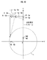
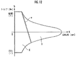
ここで、図12は縦軸を出力トルクTrとし横軸を回転数Nとして、電動機の界磁弱めが必要となる領域を示したものであり、図中uは電動機の直交ライン(界磁弱め制御を行わずに電動機を作動させたときに、回転数と出力トルクの組合わせにより電動機の相電圧が電源電圧と等しくなる点を結んだもの)である。図中Xは界磁弱めが不要な領域であり、Yは界磁弱めが必要な領域である。 Here, in FIG. 12, the vertical axis represents the output torque Tr and the horizontal axis represents the rotational speed N, and shows the region where the field weakening of the motor is required. In the figure, u represents the orthogonal line of the motor (field weakening). When the motor is operated without control, the phase voltage of the motor becomes equal to the power supply voltage by the combination of the rotation speed and the output torque). In the figure, X is a region that does not require field weakening, and Y is a region that requires field weakening.
図10に示したように、界磁弱めが必要となる領域Yは電動機の回転数Nと出力トルクTrにより決定されるため、従来の回転数のみによる界磁弱め制御では、界磁弱めの制御量が過大又は過小となるという不都合がある。 As shown in FIG. 10, the region Y where field weakening is required is determined by the rotational speed N of the motor and the output torque Tr. Therefore, in the field weakening control based only on the conventional rotational speed, the field weakening control is performed. There is a disadvantage that the amount is too large or too small.
また、本来、界磁弱め制御は、電動機の回転により電機子に生じる逆起電力を減少させて電機子の端子間電圧が電源電圧よりも大きくなることを抑制し、これにより、電動機をより高回転域で使用できるようにするものである。そして、電動機の回転数や遠心力で第1ロータと第2ロータの位相差を変更する場合には、界磁弱めを変更するパラメータが回転数のみであるため、電動機の出力トルクや回転数の制御範囲を柔軟に変更することができないという不都合がある。 In addition, the field weakening control originally reduces the counter electromotive force generated in the armature due to the rotation of the motor and suppresses the voltage between the terminals of the armature from becoming higher than the power supply voltage. It can be used in the rotation range. When the phase difference between the first rotor and the second rotor is changed by the rotational speed or centrifugal force of the electric motor, the parameter for changing the field weakening is only the rotational speed. There is an inconvenience that the control range cannot be changed flexibly.
また、発電機としても作動する電動機においては、一般的に駆動時(出力トルクが正)と発電時(出力トルクが負)では同一回転数に対する界磁の制御量を変えた方が運転効率が高くなるが、回転数や遠心力で第1ロータと第2ロータの位相差を変更するときには、このように駆動時と発電時で界磁の制御量を変えることができないという不都合がある。 In addition, in an electric motor that also operates as a generator, it is generally more efficient to change the field control amount for the same rotational speed during driving (output torque is positive) and during power generation (output torque is negative). However, when the phase difference between the first rotor and the second rotor is changed by the rotational speed or centrifugal force, there is an inconvenience that the field control amount cannot be changed between driving and power generation.
さらに、遠心力により第1ロータと第2ロータの位相差を変更する場合には、制御側では実際の位相差を検知できないため、電動機の作動状況の変化等により回転数に応じた位相差が変化する場合があり、この場合には想定した界磁弱めの効果が得られない場合がある。
本発明は上記背景を鑑みてなされたものであり、電動機の回転数に依らずに、同心円状に配置された二つのロータ間の位相差をより正確に認識して界磁弱め制御を行うことができる電動機の制御装置を提供することを目的とする。 The present invention has been made in view of the above background, and performs field weakening control by more accurately recognizing the phase difference between two rotors arranged concentrically without depending on the rotational speed of the motor. An object of the present invention is to provide an electric motor control device that can perform the above-described operation.
本発明は上記目的を達成するためになされたものであり、永久磁石による界磁を複数個有する第1ロータ及び第2ロータを、回転軸の周囲に同心円状に配置した永久磁石界磁型の回転電動機の作動を、該第1ロータと該第2ロータとの位相差であるロータ位相差を変更することによる界磁制御を行って制御する電動機の制御装置に関する。なお、前記界磁制御には、前記電動機の界磁の磁束を減少させる界磁弱め制御と、前記電動機の界磁の磁束を増大させる界磁強め制御とが含まれる。 The present invention has been made to achieve the above object, and is a permanent magnet field type in which a first rotor and a second rotor each having a plurality of field magnets are arranged concentrically around a rotating shaft. The present invention relates to a motor control device that controls the operation of a rotary motor by performing field control by changing a rotor phase difference that is a phase difference between the first rotor and the second rotor. The field control includes field weakening control for reducing the magnetic field flux of the electric motor and field strengthening control for increasing the magnetic field magnetic flux of the electric motor.
そして、前記界磁制御における前記ロータ位相差の指令値に応じて、前記ロータ位相差を変更するロータ位相差変更手段と、前記電動機の電機子に流れる電流を検出する電流検出手段と、前記第1ロータの位置を検出するロータ位置検出手段と、前記電動機の角速度を検出する角速度検出手段と、前記電動機を2相交流の固定座標系又は前記第1ロータの位置に基づく2相直流の回転座標系による等価回路に変換して扱い、前記電動機の電機子の端子間電圧及び該電機子に流れる電流の該等価回路における変換値と、前記電動機の角速度とに基づいて、前記電動機の誘起電圧定数を算出する誘起電圧定数算出手段と、該誘起電圧定数に基づいて、前記ロータ位相差を推定するロータ位相差推定手段と、該ロータ位相差推定手段による前記ロータ位相差の推定値に基づいて、前記電動機の通電制御を行う通電制御手段とを備えたことを特徴とする。 And a rotor phase difference changing means for changing the rotor phase difference according to a command value of the rotor phase difference in the field control, a current detection means for detecting a current flowing through an armature of the motor, and the first rotor. Rotor position detecting means for detecting the position of the motor, angular speed detecting means for detecting the angular speed of the electric motor, and the electric motor by a two-phase alternating current fixed coordinate system or a two-phase direct current rotational coordinate system based on the position of the first rotor. Converted to an equivalent circuit and calculated the induced voltage constant of the motor based on the converted value in the equivalent circuit of the voltage across the armature of the motor and the current flowing through the armature, and the angular velocity of the motor Induced voltage constant calculating means, rotor phase difference estimating means for estimating the rotor phase difference based on the induced voltage constant, and the low phase by the rotor phase difference estimating means. Based on the estimated value of the phase difference, characterized in that a current supply control means for performing energization control of the electric motor.
かかる本発明によれば、前記ロータ角度変更手段により、前記電動機の回転数によらずに、前記界磁制御における前記ロータ位相差の指令値に応じて前記ロータ位相差を変更することができる。そのため、前記電動機の出力トルクの指令値に応じて、前記ロータ位相差を変更して界磁制御を行うことができる。また、前記ロータ位相差が変化すると、それに応じて界磁の磁束が変化するため前記電動機の誘起電圧定数が変わる。このように、前記ロータ位相差と前記電動機の誘起電圧定数Keとの間には相間関係があるため、前記ロータ位相差推定手段は、前記誘起電圧定数算出手段により算出された前記電動機の誘起電圧定数に基づいて、前記ロータ位相差を推定することができる。そして、前記通電制御手段は、前記ロータ位相差の推定値に基づいて前記電動機の通電制御を行うことで、前記電動機の動作パラメータである実際の界磁の状態を把握しながら通電制御を行うことができる。そのため、前記電動機の運転状態と通電量の制御値との適合精度を向上させて、前記電動機を効率良く作動させることができる。 According to this invention, the rotor phase change means can change the rotor phase difference according to the command value of the rotor phase difference in the field control regardless of the rotation speed of the electric motor. Therefore, field control can be performed by changing the rotor phase difference in accordance with the command value of the output torque of the electric motor. Further, when the rotor phase difference changes, the magnetic flux of the field changes accordingly, so that the induced voltage constant of the motor changes. As described above, since there is a phase relationship between the rotor phase difference and the induced voltage constant Ke of the motor, the rotor phase difference estimating means calculates the induced voltage of the motor calculated by the induced voltage constant calculating means. The rotor phase difference can be estimated based on a constant. The energization control means performs energization control while grasping an actual field state that is an operation parameter of the motor by performing energization control of the motor based on the estimated value of the rotor phase difference. Can do. For this reason, it is possible to improve the matching accuracy between the operating state of the motor and the control value of the energization amount, and to operate the motor efficiently.
また、前記誘起電圧定数算出手段は、前記電動機の通電量が所定値以下であるときに、異なる時点間における前記電動機の電機子に流れる電流の前記等価回路による変換値の符号が異なるように、前記電動機の通電量を制御し、該時点間における前記電動機の電機子の端子間電圧の前記等価回路による変換値の差分と、該時点間における前記電動機の電機子に流れる電流の前記等価回路による変換値の差分と、前記電動機の角速度とに基づいて、前記電動機の誘起電圧定数を算出することを特徴とする。 Further, the induced voltage constant calculation means, when the energization amount of the motor is less than a predetermined value, so that the sign of the conversion value by the equivalent circuit of the current flowing through the armature of the motor at different time points is different, By controlling the energization amount of the motor, the difference between the converted values of the voltage between the terminals of the armature of the motor between the time points by the equivalent circuit, and the equivalent circuit of the current flowing through the armature of the motor between the time points An induced voltage constant of the electric motor is calculated based on a difference between conversion values and an angular velocity of the electric motor.
かかる本発明によれば、詳細は後述するが、前記電動機の通電量が所定値以下となるときに、前記異なる時点間の通電量の差分が大きくなるようにし、該通電量の差分を用いることによって前記電動機の誘起電圧定数の算出誤差を減少させることができる。 According to the present invention, as will be described in detail later, when the energization amount of the electric motor becomes a predetermined value or less, the difference in energization amount between the different time points is increased, and the difference between the energization amounts is used. Thus, the calculation error of the induced voltage constant of the electric motor can be reduced.
また、前記等価回路は、前記電動機の界磁の磁束方向であるd軸と該d軸と直交するq軸からなる2相直流の回転座標系によるものであり、前記電動機の電機子の端子間電圧及び該電機子に流れる電流の前記等価回路における変換値と、前記電動機の角速度とに基づいて、q軸側の電機子のインダクタンスを算出するq軸電機子インダクタンス算出手段を備え、前記ロータ位相差推定手段は、q軸側の電機子のインダクタンスと前記電動機の誘起電圧定数とに基づいて、前記ロータ位相差を推定することを特徴とする。 The equivalent circuit is based on a two-phase DC rotating coordinate system including a d-axis which is a magnetic flux direction of the field of the electric motor and a q-axis orthogonal to the d-axis, and between the terminals of the armature of the electric motor. Q-axis armature inductance calculating means for calculating the inductance of the armature on the q-axis side based on the converted value of the voltage and the current flowing in the armature in the equivalent circuit and the angular velocity of the motor; The phase difference estimation means estimates the rotor phase difference based on an inductance of a q-axis side armature and an induced voltage constant of the motor.
かかる本発明によれば、前記ロータ位相差が変化して界磁の磁束が変化すると、それに応じてq軸側の電機子のインダクタンスも変化する。そのため、前記誘起電圧定数算出手段により、q軸側の電機子のインダクタンスと前記電動機の誘起電圧定数とに基づいて、前記ロータ位相差を推定することによって、前記ロータ位相差の推定精度を高めることができる。 According to the present invention, when the rotor phase difference changes and the magnetic flux of the field changes, the q-axis side armature inductance changes accordingly. Therefore, the estimation accuracy of the rotor phase difference is increased by estimating the rotor phase difference based on the inductance of the q-axis side armature and the induced voltage constant of the motor by the induced voltage constant calculation means. Can do.
また、前記q軸電機子インダクタンス算出手段は、q軸側の電機子に流れる電流が所定値以下であるときに、異なる時点間におけるq軸側の電機子に流れる電流の符号が異なるように、q軸側の電機子に流れる電流を制御し、該時点間における前記電動機の電機子の端子間電圧の前記等価回路による変換値の差分と、該時点間における前記電動機の電機子に流れる電流の前記等価回路による変換値の差分と、前記電動機の角速度とに基づいて、q軸側の電機子のインダクタンスを算出することを特徴とする。 Further, the q-axis armature inductance calculating means is configured such that when the current flowing through the q-axis side armature is a predetermined value or less, the sign of the current flowing through the q-axis side armature at different time points is different. The current flowing through the armature on the q-axis side is controlled, and the difference between the converted values by the equivalent circuit of the voltage between the terminals of the armature of the motor between the time points and the current flowing through the armature of the motor between the time points The inductance of the armature on the q-axis side is calculated based on the difference between the converted values by the equivalent circuit and the angular velocity of the motor.
かかる本発明によれば、詳細は後述するが、q軸側の電機子に流れる電流が所定値以下であるときに、前記異なる時点間における前記電動機の電機子に流れる電流の前記等価回路による変換値の差分が大きくなるようにし、該差分を用いることによってq軸側の電機子のインダクタンスの算出誤差を減少させることができる。 According to the present invention, as will be described in detail later, when the current flowing through the armature on the q-axis side is equal to or less than a predetermined value, the conversion by the equivalent circuit of the current flowing through the armature of the motor between the different time points is performed. By making the difference between the values large and using the difference, it is possible to reduce the calculation error of the inductance of the armature on the q-axis side.
また、前記q軸電機子インダクタンス算出手段は、異なる時点間における前記電動機の電機子の端子間電圧の前記等価回路による変換値の差分と、該時点間における前記電動機の電機子に流れる電流の前記等価回路による変換値の差分と、前記電動機の角速度とに基づいて、q軸側の電機子のインダクタンスを算出することを特徴とする。 Further, the q-axis armature inductance calculating means is configured to calculate the difference between the converted values by the equivalent circuit of the voltage between the terminals of the motor armature at different time points and the current flowing through the armature of the motor between the time points. The inductance of the armature on the q-axis side is calculated on the basis of the difference between the converted values by the equivalent circuit and the angular velocity of the motor.
かかる本発明によれば、詳細は後述するが、異なる時点間における前記電動機の電機子の端子間電圧の前記等価回路による変換値の差分と、該時点間における前記電動機の電機子に流れる電流の前記等価回路による変換値の差分とを用いることにより、前記電動機の電機子に流れる電流が微小であるときに、前記電動機のq軸側の電機子のインダクタンスの算出誤差が大きくなることを抑制することができる。 According to the present invention, as will be described in detail later, the difference between the converted values by the equivalent circuit of the voltage between the terminals of the armature of the motor between different time points, and the current flowing through the armature of the motor between the time points By using the difference between the converted values by the equivalent circuit, it is possible to suppress an increase in the calculation error of the inductance of the armature on the q-axis side of the motor when the current flowing through the armature of the motor is very small. be able to.
また、前記誘起電圧定数算出手段は、前記界磁制御における前記ロータ位相差の指令値に応じてd軸側の電機子のインダクタンスを推定し、該d軸側の電機子のインダクタンスの推定値を用いて前記誘起電圧定数を算出することを特徴とする。 The induced voltage constant calculating means estimates the inductance of the armature on the d-axis side according to a command value of the rotor phase difference in the field control, and uses the estimated value of the inductance of the armature on the d-axis side. The induced voltage constant is calculated.
かかる本発明によれば、前記ロータ位相差の変化に応じて、d軸側の電機子のインダクタンスLdが変化するため、q軸側の電機子のインダクタンス及び前記電動機の誘起電圧定数に加えて、d軸側の電機子のインダクタンスを用いて前記ロータ位相差を推定することによって、該ロータ位相差の推定精度をさらに高めることができる。 According to the present invention, since the inductance Ld of the armature on the d-axis side changes according to the change in the rotor phase difference, in addition to the inductance of the armature on the q-axis side and the induced voltage constant of the motor, By estimating the rotor phase difference using the inductance of the armature on the d-axis side, the estimation accuracy of the rotor phase difference can be further increased.
また、前記界磁制御により前記電動機の界磁を弱めるときの前記ロータ位相差の指令値と、前記位相差推定手段による前記ロータ位相差の推定値との偏差に応じて、前記ロータ位相差の変更による界磁弱めの不足分を減少させるように、d軸側の電機子の通電量を制御する界磁弱め電流補正手段を備えたことを特徴とする。 Further, by changing the rotor phase difference according to a deviation between the command value of the rotor phase difference when the field of the motor is weakened by the field control and the estimated value of the rotor phase difference by the phase difference estimating means A field weakening current correcting means for controlling the energization amount of the armature on the d-axis side is provided so as to reduce the shortage of field weakening.
かかる本発明によれば、前記ロータ位相差変更手段の応答遅れ等により、前記界磁制御により前記電動機の界磁を弱めるときの前記ロータ位相差の指令値と推定値との偏差が生じたときに、前記界磁弱め電流補正手段により、前記ロータ位相差の変更による界磁弱めの不足分を減少させるように、d軸側の電機子の通電量が制御される。そのため、前記ロータ位相差変更手段の応答遅れ等の影響により、界磁弱めの不足が生じることを抑制することができる。 According to the present invention, when a deviation occurs between the command value and the estimated value of the rotor phase difference when the field of the electric motor is weakened by the field control due to a response delay of the rotor phase difference changing unit, The energization amount of the armature on the d-axis side is controlled by the field weakening current correcting means so as to reduce the shortage of field weakening due to the change in the rotor phase difference. For this reason, it is possible to suppress the occurrence of insufficient field weakening due to the response delay of the rotor phase difference changing means.
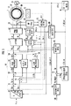
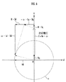
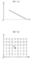
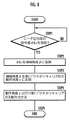
本発明の実施の形態について、図1〜図11を参照して説明する。図1は2重ロータを備えたDCブラシレスモータの構成図、図2は図1に示したDCブラシレスモータの外側ロータと内側ロータの位相差を変更する機構の構成図及び作動説明図、図3及び図4は外側ロータと内側ロータの位相差を変更することによる効果の説明図、図5は電動機の制御装置の制御ブロック図、図6はdq座標系における電圧ベクトル図、図7は誘起電圧定数を決定するためのデータテーブルの説明図、図8は外側ロータと内側ロータの位相差を変更する処理のフローチャート、図9は外側ロータと内側ロータの位相差の指令値に対する推定値の追従遅れを補う処理のフローチャート、図10は誘起電圧定数の算出精度を向上させるための処理の説明図、図11は誘起電圧定数の算出に使用されるデータテーブルの説明図である。 Embodiments of the present invention will be described with reference to FIGS. FIG. 1 is a configuration diagram of a DC brushless motor having a double rotor, FIG. 2 is a configuration diagram and an operation explanatory diagram of a mechanism for changing a phase difference between an outer rotor and an inner rotor of the DC brushless motor shown in FIG. And FIG. 4 is an explanatory diagram of the effect of changing the phase difference between the outer rotor and the inner rotor, FIG. 5 is a control block diagram of the motor control device, FIG. 6 is a voltage vector diagram in the dq coordinate system, and FIG. FIG. 8 is a flowchart of processing for changing the phase difference between the outer rotor and the inner rotor, and FIG. 9 is a tracking delay of the estimated value with respect to the command value of the phase difference between the outer rotor and the inner rotor. FIG. 10 is an explanatory diagram of processing for improving the calculation accuracy of the induced voltage constant, and FIG. 11 is an explanatory diagram of a data table used for calculating the induced voltage constant. That.
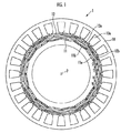
図1を参照して、本実施の形態における電動機1は、永久磁石11a,11bの界磁が周方向に沿って等間隔に配設された内側ロータ11(本発明の第2のロータに相当する)と、永久磁石12a,12bの界磁が周方向に沿って等間隔に配設された外側ロータ12(本発明の第1のロータに相当する)と、内側ロータ11及び外側ロータ12に対する回転磁界を発生させるための電機子10aを有するステータ10とを備えたDCブラシレスモータである。電動機1は、例えばハイブリッド車両や電動車両の駆動源として使用され、ハイブリッド車両に搭載されたときは、電動機及び発電機として動作する。
Referring to FIG. 1, an electric motor 1 according to the present embodiment includes an inner rotor 11 (corresponding to a second rotor of the present invention) in which the fields of
内側ロータ11と外側ロータ12は、共に回転軸が電動機1の回転軸2と同軸となるように同心円状に配置されている。そして、内側ロータ11においては、N極を回転軸2側とする永久磁石11aとS極を回転軸2側とする永久磁石11bが交互に配設されている。同様に、外側ロータ12においても、N極を回転軸2側とする永久磁石12aとS極を回転軸2側とする永久磁石12bが交互に配設されている。
The
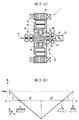
次に、電動機1は、外側ロータ12と内側ロータ11の位相差であるロータ位相差を変更するために、図2(a)に示した遊星歯車機構30を備えている。図2(a)を参照して、遊星歯車機構30は、内側ロータ11の内周側の中空部に配置されたシングルピニオン型の遊星歯車機構であり、外側ロータ12と同軸且つ一体に形成された第1リングギアR1、内側ロータ11と同軸且つ一体に形成された第2リングギアR2、第1リングギアR1と噛合する第1プラネタリギア31、第2リングギアR2に噛合する第2プラネタリギア32、第1プラネタリギア31及び第2プラネタリギア32と噛合するアイドルギアであるサンギアS、第1プラネタリギア31を回転自在に支持すると共に回転軸2に回転可能に軸支された第1プラネタリキャリアC1、及び第2プラネタリギア32を回転自在に支持すると共にステータ10に固定された第2プラネタリキャリアC2を備えている。
Next, the electric motor 1 includes the
遊星歯車機構30において、第1リングギアR1と第2リングギアR2は略同等のギア形状とされ、第1プラネタリギア31と第2プラネタリギア32も略同等のギア形状とされている。また、サンギアSの回転軸33は電動機1の回転軸2と同軸に配置されると共に、軸受け34により回転可能に軸支されている。そして、これにより、第1プラネタリギア31と第2プラネタリギア32がサンギアSと噛合し、外側ロータ12と内側ロータ11が同期して回転するように構成されている。
In the
さらに、第1プラネタリキャリアC1の回転軸35は、電動機1の回転軸2と同軸に配置されると共にアクチュエータ25に接続されており、第2プラネタリキャリアC2はステータ10に固定されている。
Further, the
アクチュエータ25は、外部から入力される制御信号に応じて、油圧により第1プラネタリキャリアC1を正転方向又は逆転方向に回転させ、或いは回転軸2回りの第1プラネタリキャリアC1の回転を規制する。そして、アクチュエータ25によって第1プラネタリキャリアC1が回転すると、外側ロータ12と内側ロータ11間の相対的な位置関係(位相差)が変化する。なお、遊星歯車機構30とアクチュエータ25により、本発明のロータ位相差変更手段が構成される。
The
図2(b)は、遊星歯車機構30における第1リングギアR1と、第1プラネタリキャリアC1と、サンギアSと、第2プラネタリキャリアC2と、第2リングギアR2の回転速度の関係を示した図であり、縦軸が各ギアの回転速度Vrに設定されている。
FIG. 2B shows the relationship among the rotational speeds of the first ring gear R1, the first planetary carrier C1, the sun gear S, the second planetary carrier C2, and the second ring gear R2 in the
図2(b)において、ステータ10に固定された第2プラネタリキャリアC2の速度はゼロである。そのため、第2リングギアR2及び内側ロータ11は、例えば逆転方向(Vr<0)に回動するサンギアSに対して、第2リングギアR2に対するg2に応じた速度で正転方向(Vr>0)に回転することになる。
In FIG. 2B, the speed of the second planetary carrier C2 fixed to the
ここで、アクチュエータ25が非作動状態(アクチュエータ25による第1プラネタリキャリアC1の回動がなされていない状態)にあるときは、第1プラネタリキャリアC1の回転速度はゼロである。そのため、第1リングギアR1及び外側ロータ12は、回転するサンギヤSに対して、第1リングギアR1に対するサンギアSのギア比g1に応じた速度で逆方向に回転する。そして、ギヤ比g1とギヤ比g2は略同等(g1≒g2)に設定されているので、内側ロータ11と外側ロータ12は同期して回転し、内側ロータ11と外側ロータ12間の位相差が一定に維持される。
Here, when the
一方、アクチュエータ25が作動状態(アクチュエータ25により第1プラネタリキャリアC1が回動している状態)にあるときは、第1リングギアR1及び外側ロータ12は、回転するサンギアSに対して、第1リングギアR1に対するサンギアSのギア比g1に応じた速度に対して、第1プラネタリキャリアC1の回動分だけ増速又は減速されて、逆方向に回転する。そして、これにより、外側ロータ12と内側ロータ11の位相差が変化する。
On the other hand, when the
また、アクチュエータ25は、第1リングギアR1に対するサンギアSのギア比g1と電動機1の極対数Pに対して、少なくとも、機械角度β(度)=(180/P)×g1/(1+g1)だけ、第1プラネタリキャリアC1を正転方向又は逆転方向に回動可能に構成されている。
The
そのため、外側ロータ12と内側ロータ11の位相差は、少なくとも電気角で180度の範囲で進角側又は遅角側に変更することができ、電動機1の状態は、外側ロータ12の永久磁石12a,12bと内側ロータ11の永久磁石11a,11bが同極同士を対向して配置された界磁弱め状態と、外側ロータ12の永久磁石12a,12bと内側ロータ11の永久磁石11a,11bが異極同士を対向して配置された界磁強め状態との間で、適宜設定可能である。
Therefore, the phase difference between the
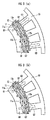
図3(a)は界磁強め状態を示しており、外側ロータ12の永久磁石12a,12bの磁束Q2と内側ロータ11の永久磁石11a,11bの磁束Q1の向きが同一であるため、合成された磁束Q3が大きくなる。一方、図3(b)は界磁弱め状態を示しており、外側ロータ12の永久磁石12a,12bの磁束Q2と内側ロータ11の永久磁石11a,11bの磁束Q1の向きが逆であるため、合成された磁束Q3が小さくなる。
FIG. 3 (a) shows a field strengthening state. Since the directions of the magnetic flux Q2 of the
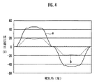
図4は、図3(a)の状態と図3(b)の状態において、電動機1を所定回転数で作動させた場合にステータ10の電機子に生じる誘起電圧を比較したグラフであり、縦軸が誘起電圧(V)に設定され、横軸が電気角(度)に設定されている。図中aが図3(a)の状態(界磁強め状態)であり、bが図3(b)の状態(界磁弱め状態)である。図4から、外側ロータ12と内側ロータ11の位相差を変更することで、生じる誘起電圧のレベルが大幅に変化していることがわかる。
FIG. 4 is a graph comparing the induced voltages generated in the armature of the
そして、このように、外側ロータ12と内側ロータ11の位相差を変更して、界磁の磁束を増減させることにより、電動機1の誘起電圧定数Keを変化させることができる。これにより、誘起電圧定数Keが一定である場合に比べて、電動機1の出力及び回転数に対する運転可能領域を拡大することができる。また、電動機の制御として一般的なdq座標変換により、d軸(界磁軸)側の電機子に通電して界磁弱め制御を行う場合に比べて、電動機1の銅損が減少するため、電動機1の運転効率を高めることができる。
Thus, the induced voltage constant Ke of the electric motor 1 can be changed by changing the phase difference between the
次に、図5〜図9を参照して、本発明の電動機の制御装置について説明する。図5に示した電動機の制御装置(以下、単に制御装置という)は、電動機1を界磁方向をd軸としてd軸と直交する方向をq軸とした2相直流の回転座標系による等価回路に変換して扱い、外部から与えられるトルク指令値Tr_cに応じたトルクが電動機1から出力されるように、電動機1に対する通電量を制御するものである。 Next, the motor control apparatus of the present invention will be described with reference to FIGS. The motor control device (hereinafter simply referred to as control device) shown in FIG. 5 is an equivalent circuit based on a two-phase DC rotating coordinate system in which the motor 1 has a field direction as a d-axis and a direction orthogonal to the d-axis as a q-axis. The amount of current supplied to the motor 1 is controlled so that torque according to the torque command value Tr_c given from the outside is output from the motor 1.
制御装置はCPU、メモリ等により構成される電子ユニットであり、トルク指令値Tr_cと電動機1の外側ロータ12と内側ロータ11の位相差(ロータ位相差)の推定値θd_eとに基づいて、d軸側の電機子(以下、d軸電機子という)の通電量(以下、d軸電流という)の指令値Id_cとq軸側の電機子(以下、q軸電機子という)の通電量(以下、q軸電流という)の指令値Iq_cとを決定する電流指令値決定部60、電流センサ70,71(本発明の電流検出手段に相当する)により検出されてバンドパスフィルタ72により不要成分が除去された電流検出信号と、レゾルバ73(本発明のロータ位置検出手段に相当する)により検出される外側ロータ12のロータ角度θrとに基づいて、3相/dq変換によりd軸電流の検出値Id_sとq軸電流の検出値Iq_sとを算出する3相/dq変換部75、d軸電流の指令値Id_cと検出値Id_sの偏差及びq軸電流の指令値Iq_cと検出値Iq_sの偏差が減少するように、d軸電機子に印加する電圧(以下、d軸電圧という)の指令値Vd_cとq軸電機子に印加する電圧(以下、q軸電圧という)の指令値Vq_cとを決定する通電制御部50、d軸電圧の指令値Vd_cとq軸電圧の指令値Vq_cを大きさV1と角度θの成分に変換するrθ変換部61、及び該大きさV1と角度θの成分をPWM制御により3相(U,V,W)の交流電圧に変換するPWM演算部62を備えている。なお、電流指令値決定部60と通電制御部50により、本発明の通電制御手段が構成される。
The control device is an electronic unit including a CPU, a memory, and the like, and is based on the torque command value Tr_c and the estimated value θd_e of the phase difference (rotor phase difference) between the
さらに、制御装置は、d軸電圧の指令値Vd_c及びq軸電圧の指令値Vq_cとd軸電流の検出値Id_s及びq軸電流の検出値Iq_sと角速度の検出値ω_s(図示しない角速度検出手段により検出される)とに基づいて、電動機1の誘起電圧定数Keとq軸電機子のインダクタンスLqとを算出する定数算出部63(本発明の誘起電圧定数算出手段とq軸電機子インダクタンス算出手段の機能を含む)、誘起電圧定数Keとq軸電機子のインダクタンスLqに基づいてロータ位相差の推定値θd_eを求める位相差推定部64(本発明の位相差推定手段に相当する)と、電動機1の電源電圧Vdcから後述する目標電圧円の半径Vp_targetを算出する目標電圧円算出部90、d軸電圧指令Vd_cとq軸電圧指令Vq_cを合成した後述する実電圧円の半径Vpを算出する実電圧円算出部92、目標電圧円の半径Vp_targetと実電圧円の半径Vpとの偏差ΔVpを算出する減算器91、該偏差ΔVpに応じて界磁弱め制御の必要電流ΔId_volを算出する界磁弱め電流算出部93、該必要電流ΔId_volをd軸電機子に流した場合と同等の界磁弱め効果を生じさせるためのロータ位相差の指令値θd_c(本発明の界磁弱め制御におけるロータ位相差の指令値に相当する)を決定するロータ位相差指令値決定部94、及びロータ位相差の指令値θd_cと推定値θd_eとの偏差に応じて、d軸電流の補正値ΔId_vol_2を算出するd軸電流補正部80(本発明の界磁弱め電流補正手段に相当する)を備えている。
Further, the control device provides a command value Vd_c for the d-axis voltage, a command value Vq_c for the q-axis voltage, a detected value Id_s for the d-axis current, a detected value Iq_s for the q-axis current, and a detected value ω_s for angular velocity (by an angular velocity detecting means not shown). The constant calculation unit 63 (the induced voltage constant calculation means and the q-axis armature inductance calculation means of the present invention) calculates the induced voltage constant Ke of the motor 1 and the inductance Lq of the q-axis armature based on A phase difference estimating unit 64 (corresponding to the phase difference estimating means of the present invention) for obtaining an estimated value θd_e of the rotor phase difference based on the induced voltage constant Ke and the inductance Lq of the q-axis armature, and the motor 1 A target voltage
また、通電制御部50は、d軸電流の指令値Id_cに補正電流ΔId_vol_2を加算する加算器51、補正電流ΔId_vol_2が加算された指令値Id_caとd軸電流の検出値Id_sとの偏差ΔIdを算出する減算器52、該偏差ΔIdを生じさせるためのd軸偏差電圧ΔVdを算出するd軸電流制御部53、補正後のd軸電流の指令値Id_caとq軸電流の指令値Iq_cとに基づいて、d軸とq軸間で干渉し合う速度起電力の影響を打ち消すための成分(非干渉成分)を算出する非干渉制御部56、d軸偏差電圧ΔVから非干渉制御部56により算出された非干渉成分を減じる減算器54、q軸電流の指令値Iq_cと検出値Iq_sとの偏差ΔIqを算出する減算器55、該偏差ΔIqを生じさせるためのq軸偏差電圧ΔVqを算出するq軸電流制御部57、及びq軸偏差電圧ΔVqに非干渉成分を加える加算器58を備えている。
The
図6は、dq座標系における電流と電圧の関係を示したものであり、縦軸がq軸(トルク軸)とされ、横軸がd軸(界磁軸)とされている。図中Cは目標電圧円である。そして、制御装置は、d軸電機子の端子間電圧Vdとq軸電機子の端子間電圧Vqの合成ベクトル(実電圧円の半径となる)が、目標電圧円C内に入るように、d軸電流とq軸電流を制御する。なお、図中Eは電動機1の回転によりq軸電機子に生じる逆起電力、ωは電動機1の角速度、Rはd軸電機子及びq軸電機子の抵抗、Lqはq軸電機子のインダクタンス、Ldはd軸電機子のインダクタンス、Vdはd軸電機子の端子間電圧、Vqはq軸電機子の端子間電圧、Idはd軸電流、Iqはq軸電流である。 FIG. 6 shows the relationship between current and voltage in the dq coordinate system, where the vertical axis is the q axis (torque axis) and the horizontal axis is the d axis (field axis). In the figure, C is a target voltage circle. Then, the control device sets the d-axis armature terminal voltage Vd and the q-axis armature terminal voltage Vq so that the combined vector (which is the radius of the actual voltage circle) falls within the target voltage circle C. Axial current and q-axis current are controlled. In the figure, E is a counter electromotive force generated in the q-axis armature by the rotation of the motor 1, ω is the angular velocity of the motor 1, R is the resistance of the d-axis armature and the q-axis armature, and Lq is the inductance of the q-axis armature. , Ld is the inductance of the d-axis armature, Vd is the voltage between the terminals of the d-axis armature, Vq is the voltage between the terminals of the q-axis armature, Id is the d-axis current, and Iq is the q-axis current.
図6のq軸側の成分について、以下の式(1)の関係が成立するため、以下の式(2)から電動機1の誘起電圧定数Keを算出することができる。 Since the relationship of the following formula (1) is established for the component on the q-axis side in FIG. 6, the induced voltage constant Ke of the electric motor 1 can be calculated from the following formula (2).
![]()
![]()
但し、Ke:誘起電圧定数、ω:電動機の角速度、R:q軸電機子及びd軸電機子の抵抗、Iq:q軸電流、Vq:q軸電機子の端子間電圧、Ld:d軸電機子のインダクタンス、Id:d軸電流。 Where Ke: induced voltage constant, ω: angular velocity of motor, R: resistance of q-axis armature and d-axis armature, Iq: q-axis current, Vq: voltage between terminals of q-axis armature, Ld: d-axis electric machine Child inductance, Id: d-axis current.
![]()
![]()
また、図6のd軸側の成分について、以下の式(3)の関係が成立するため、以下の式(4)からq軸電機子のインダクタンスLqを算出することができる。 Moreover, since the relationship of the following formula | equation (3) is materialized about the component of the d-axis side of FIG. 6, the inductance Lq of a q-axis armature is computable from the following formula | equation (4).
![]()
![]()

そこで、定数算出部63は、q軸指令電圧Vq_c、電機子1の角速度の検出値ω_s、d軸電流の検出値Id_s、及びq軸電流の検出値Iq_sを、上記式(2)のVq、ω、Id、及びIqにそれぞれ代入して、誘起電圧定数Keを算出する。また、定数算出部63は、d軸電流の検出値Id、d軸電圧の指令値Vd_c、電機子1の角速度の検出値ω_s、及びq軸電流の検出値Iqを、上記式(4)のId、Vd、ω、及びIqにそれぞれ代入して、q軸電機子のインダクタンスLqを算出する。
Therefore, the
なお、上記式(2),式(4)におけるd軸電機子及びq軸電機子の抵抗Rは、予め設定した固定値である。また、上記式(2)におけるd軸電機子のインダクタンスLdは、予め設定した固定値としてもよいが、ロータ位相差が大きくなるほどd軸電機子のインダクタンスLdが小さくなるので、ロータ位相差の指令値θd_cが大きいほどインダクタンスLdが小さくなるようにした推定値を用いてもよい。 In addition, the resistance R of the d-axis armature and the q-axis armature in the above formulas (2) and (4) is a preset fixed value. Further, the inductance Ld of the d-axis armature in the above formula (2) may be a fixed value set in advance. However, since the inductance Ld of the d-axis armature decreases as the rotor phase difference increases, the rotor phase difference command An estimated value in which the inductance Ld is decreased as the value θd_c is increased may be used.
次に、位相差推定部64は、定数算出部63により算出された誘起電圧定数Keとq軸電機子のインダクタンスLqとに基づいて、ロータ位相差の推定値θd_eを求める。ここで、ロータ位相差が変化すると、それに応じて電動機1の誘起電圧定数Keとq軸電機子のインダクタンスLqが変化する。
Next, the phase
そこで、位相差推定部64は、図7(b)に示したKe,Lq/θdの対応マップに、定数算出部63により算出された誘起電圧定数Keとq軸電機子のインダクタンスLqとを適用して対応する位相差θdを取得し、該位相差θdを外側ロータ12と内側ロータ11の位相差の推定値θd_eとする。
Therefore, the phase
なお、Ke,Lq/θdの対応マップは、実験データやコンピュータシミュレーションに基づいて作成され、予めメモリ(図示しない)に記憶されている。また、図7(a)に示したKe/θdの対応マップに、定数算出部63により算出された誘起電圧定数Keを適用して、θd_eを求めることもできるが、誘起電圧定数Keに加えてq軸電機子のインダクタンスLqを用いてロータ位相差の推定値θd_eを求めることで、ロータ位相差の推定精度を高めることができる。
The correspondence map of Ke and Lq / θd is created based on experimental data and computer simulation, and is stored in advance in a memory (not shown). In addition, the induced voltage constant Ke calculated by the constant calculating
そして、電流指令値決定部60は、Tr,θd/Id,Iqマップに、トルク指令値Tr_cと、ロータ位相差の推定値θd_eを適用して、対応するId,Iqを取得し、該取得したId,Iqをそれぞれd軸電流指令値Id_c及びq軸電流指令値として決定する。このように、ロータ位相差の推定値θd_eを用いることで、実際の電動機1の界磁の磁束の変化を反映したd軸電流指令値Id_c及びq軸電流指令値Iq_cを決定することができる。そのため、トルク指令値Tr_cに対して電動機1の出力トルクを精度良く制御することができる。
Then, the current command
次に、目標電圧円算出部90は、直流電源(図示しない)の出力電圧Vdc内で目標電圧Vp_targetを算出し、実電圧円算出部92は、d軸電流の指令値Id_cとq軸電流の指令値Iq_cをdq座標で合成ベクトルの大きさを算出する。そして、減算器91により、目標電圧Vp_targetと実電圧Vpの偏差ΔVpが算出され、界磁弱め制御部93は、ΔVp>0となるように、d軸電流の変更値ΔId_volを決定する。
Next, the target voltage
Id/θd置換部94は、ΔId_volに相当する界磁の変化を生じさせるロータ位相差の指令値θd_cを決定する。そして、Id/θd置換部94は、ロータ位相差の指令値θd_cをアクチュエータ25に出力し、アクチュエータ25は、図8に示した処理を実行してロータ位相差を変更する。
The Id /
すなわち、アクチュエータ25は、図8のSTEP1でロータ位相差の指令値θd_cを受信すると、STEP2でθd_cを機械角度βに変換する。そして、続くSTEP3で、アクチュエータ25は機械角度βを第1プラネタリキャリアC1の動作角度γに変換し、STEP4で該動作角度γ分だけ、第1プラネタリキャリアを回動させる。
That is, when the
また、ロータ位相差追従判定部80は、図9に示した処理を実行して、アクチュエータ25によるロータ位相差の変更処理の応答遅れを補うための処理を実行する。すなわち、位相差追従判定部80は、図9のSTEP10でロータ位相差の指令値θd_cと推定値θd_eを読み込み、次のSTEP11で指令値θd_cよりも推定値θd_eの方が小さいか否かを判断する。
Further, the rotor phase difference follow-up
そして、指令値θd_cよりも推定値θd_eの方が小さいとき(追従遅れが生じているとき)はSTEP12に進み、d軸電流補正値ΔId_vol_2にd軸電流変更値ΔId_volをセットしてSTEP13に進む。一方、指令値θd_cが推定値θd_e以下であるとき(追従遅れが生じていないとき)には、STEP11からSTEP20に分岐して、d軸電流補正値ΔId_vol_2にゼロをセットし、STEP13に進む。そして、STEP13で、ロータ位相差追従判定部80は、d軸電流補正値ΔId_vol_2を加算器51に出力する。
When the estimated value θd_e is smaller than the command value θd_c (when a follow-up delay occurs), the process proceeds to STEP12, the d-axis current change value ΔId_vol is set to the d-axis current correction value ΔId_vol_2, and the process proceeds to STEP13. On the other hand, when the command value θd_c is equal to or less than the estimated value θd_e (when no follow-up delay occurs), the process branches from STEP11 to STEP20, zero is set to the d-axis current correction value ΔId_vol_2, and the process proceeds to STEP13. Then, in STEP 13, the rotor phase difference follow-up
これにより、ロータ位相差の変更処理の応答遅れが生じているときは、加算器51において、d軸電流の指令値Id_cにd軸電流変更値ΔId_vol分のd軸電流補正値ΔId_vol_2が加算される。そして、d軸電流の増加により界磁弱めの効果が増すため、ロータ位相差の変更処理の応答遅れによって、ロータ位相差の変更による界磁弱めの不足分を補うことができる。
As a result, when a response delay of the rotor phase difference change process occurs, the
次に、図10及び図11を参照して、電動機の電機子の抵抗Rを考慮して誘起電圧定数Keを算出するときに、誘起電圧定数Keの算出精度を向上させるための処理について説明する。 Next, a process for improving the calculation accuracy of the induced voltage constant Ke when calculating the induced voltage constant Ke in consideration of the resistance R of the armature of the motor will be described with reference to FIGS. .
図10において、(Id1,Iq1,Vd1,Vq1)は、制御装置の今回の制御サイクルCy1におけるd軸電流及びq軸電流のサンプリング時点t1の(d軸電流の検出値Id_s、q軸電流の検出値Iq_s,d軸電圧の指令値Id_c,q軸電圧の指令値Iq_c)を示しており、(Id2,Iq2,Vd2,Vq2)は、前回の制御サイクルCy2におけるd軸電流及びq軸電流のサンプリング時点t2の(d軸電流の検出値Id_s、q軸電流の検出値Iq_s,d軸電圧の指令値Id_c,q軸電圧の指令値Iq_c)である。なお、t2における(Id2,Iq2,Vd2,Vq2)のデータはメモリに記憶されている。 In FIG. 10, (Id 1 , Iq 1 , Vd 1 , Vq 1 ) is the d-axis current detection value Id_s at the sampling time t 1 of the d-axis current and the q-axis current in the current control cycle Cy 1 of the control device. , Q-axis current detection value Iq_s, d-axis voltage command value Id_c, q-axis voltage command value Iq_c), (Id 2 , Iq 2 , Vd 2 , Vq 2 ) are the previous control cycle Cy is the sampling time point t 2 of the d-axis current and q-axis current in the two (the detected value of the d-axis current Id_s, the detected value of q-axis current Iq_s, command values of the d-axis voltage Id_c, a command value of the q-axis voltage Iq_c) . The data of (Id 2 , Iq 2 , Vd 2 , Vq 2 ) at t 2 is stored in the memory.
ここで、制御装置の制御サイクルは短時間であるため、t1からt2の間においては、電動機1の電機子のコイルの温度変化や内側ロータ11及び外側ロータ12の温度変化の影響は無視することができる程度であり、内側ロータ11と外側ロータ12の位相差は変化しないと想定することができる。
Here, since the control cycle of the control device is short, the influence of the temperature change of the armature coil of the electric motor 1 and the temperature change of the
そこで、定数算出部63は、上記式(3)にt1における(Id1,Iq1,Vd1)を代入した以下の式(5)と、上記式(3)にt2における(Id2,Iq2,Vd2)を代入した以下の式(6)との差をとって得られる以下の式(7)に、図11(b)に示したq軸電機子のインダクタンスLqと電動機1の出力トルクTrの対応マップ(Lq/Trマップ)により得られるLqを代入して、電機子の抵抗Rを算出する。なお、図11(b)のLq/Trマップは、q軸電機子のインダクタンスLqが電動機1の出力トルクに応じて変化するという特性に基づいて、実験データやコンピュータシミュレーションにより決定されたものである。
Therefore, the constant calculating
但し、Vd1:t1におけるd軸電機子の端子間電圧、R:q軸電機子及びd軸電機子の抵抗、Id1:t1におけるd軸電流、ω:電動機の角速度、Lq:q軸電機子のインダクタンス、Iq1:t1におけるq軸電流。 Where Vd 1 : terminal voltage of the d-axis armature at t 1 , R: resistance of the q-axis armature and d-axis armature, Id 1 : d-axis current at t 1 , ω: angular velocity of the motor, Lq: q Shaft armature inductance, Iq 1 : q-axis current at t 1 .
但し、Vd2:t2におけるd軸電機子の端子間電圧、R:q軸電機子及びd軸電機子の抵抗、Id2:t2におけるd軸電流、ω:電動機の角速度、Lq:q軸電機子のインダクタンス、Iq2:t2におけるq軸電流。 Where Vd 2 : terminal voltage of the d-axis armature at t 2 , R: resistance of the q-axis armature and d-axis armature, Id 2 : d-axis current at t 2 , ω: angular velocity of the motor, Lq: q Shaft armature inductance, Iq 2 : q-axis current at t 2 .
ここで、上記式(5)を変形した以下の式(8)により抵抗Rを算出した場合、Id1がゼロ近傍に設定された所定値以下であるときにはRの算出誤差が大きくなってしまう。 Here, when the resistance R is calculated by the following equation (8) obtained by modifying the above equation (5), the calculation error of R becomes large when Id 1 is equal to or less than a predetermined value set near zero.
そこで、定数算出部63は、t1におけるd軸電流Id1とt2におけるd軸電流Id2が、符号が異なる微小電流となるように、d軸電流の指令値Id_cを設定する。これにより、上記式(8)の分母におけるId1よりも、上記式(7)の分母におけるId1−Id2の方が絶対値が大きくなり、抵抗Rの算出誤差を減少させることができる。例えば、電流指令値決定部60によりId_c≒0が出力されているときに、制御サイクルCy1のd軸電流の指令値Id_c=0.1とし、制御サイクルCy2のd軸電流の指令値をId_c=-0.1に設定することで、上記式(7)の分母をId1−Id2=0.1−(-0.1)=0.2と大きくすることができる。この場合、制御サイクルCy1とCy2のd軸電流の平均はゼロとなるので、電動機1の通電制御に与える影響は小さい。
Therefore, the
そして、定数算出部63は、以下の式(9)に、上記式(8)で算出された抵抗Rと、図11(a)に示したd軸電機子のインダクタンスLdと電動機1の出力トルクTrの対応マップ(Lq/Trマップ)により得られるLdを代入して、誘起電圧定数Keを算出する。
The
なお、図11(a)のLd/Trマップは、d軸電機子のインダクタンスLdが電動機1の出力トルクに応じて変化するという特性に基づいて、実験データやコンピュータシミュレーションにより決定されたものである。 Note that the Ld / Tr map in FIG. 11A is determined by experimental data or computer simulation based on the characteristic that the inductance Ld of the d-axis armature changes according to the output torque of the electric motor 1. .
そして、定数算出部63は、上記式(9)により算出した誘起電圧定数Keを、図7(a)に示したKe/θdの対応マップに適用して、電動機1の外側ロータ12と内側ロータ11の位相差の推定値θd_eを求める。
The constant calculating
次に、上述した図7(b)のKe,Lq/θdの対応マップより、ロータ位相差θdを求める場合にも、同様にして誘起電圧定数Keとq軸電機子のインダクタンスLqの算出精度を減少させることができる。 Next, when obtaining the rotor phase difference θd from the correspondence map of Ke and Lq / θd in FIG. 7B, the calculation accuracy of the induced voltage constant Ke and the inductance Lq of the q-axis armature is similarly obtained. Can be reduced.
上記式(4)にt1における(Id1,Iq1,Vd1)を代入した以下の式(10)により、q軸電機子のインダクタンスLqを算出した場合、Iq1が微小(≒0)であるときにLqの算出誤差が大きくなる。 When the inductance Lq of the q-axis armature is calculated by the following equation (10) in which (Id 1 , Iq 1 , Vd 1 ) at t 1 is substituted into the above equation (4), Iq 1 is very small (≈0). In this case, the calculation error of Lq becomes large.
そこで、定数算出部63は、t1におけるq軸電流Iq1とt2におけるq軸電流Iq2が、符号が異なる微小電流となるようにq軸電流の指令値Iq_cを設定し、以下の式(11)により、q軸電機子のインダクタンスLqを算出する。
Therefore, constant calculating
これにより、上記式(10)の分母におけるIq1よりも上記式(11)の分母の(Iq1−Iq2)の方が絶対値が大きくなり、q軸電機子のインダクタンスLqの算出誤差を減少させることができる。 As a result, the absolute value of (Iq 1 −Iq 2 ) in the denominator of the above equation (11) becomes larger than Iq 1 in the denominator of the above equation (10), and the calculation error of the inductance Lq of the q-axis armature is reduced. Can be reduced.
なお、上記式(11)における抵抗Rは、例えば電動機についての以下の式(12)〜式(17)により算出することができる。 The resistance R in the above equation (11) can be calculated by, for example, the following equations (12) to (17) for the electric motor.
電動機に通電されているときのq軸電流Iqは、以下の式(12)で与えられる。 The q-axis current Iq when the motor is energized is given by the following equation (12).
そして、d軸電機子及びq軸電機子の端子間を短絡して、Vd=0、Vq=0とすると、上記式(12)は以下の式(13)となる。 When the terminals of the d-axis armature and the q-axis armature are short-circuited and Vd = 0 and Vq = 0, the above equation (12) becomes the following equation (13).
また、d軸電機子及びq軸電機子の短絡時に電動機の出力トルクがほぼ一定となり、通電電流も一定となる領域に限定すると、上記式(13)の分母において、R2<<ω2・Ld・Lqが成立するため、以下の式(14)の形になる。 Further, if the output torque of the motor is substantially constant when the d-axis armature and the q-axis armature are short-circuited, and is limited to a region where the energization current is also constant, in the denominator of the above equation (13), R 2 << ω 2. Since Ld · Lq holds, the following equation (14) is obtained.
ここで、電機子コイルの基準温度T0と現在温度Tcとの差及び温度係数Ktを考慮して以下の式(15)とし、式(15)をTcについて変形して式(16)を得る。そして、式(16)に上記式(14)を代入して、以下の式(17)が得られる。 Here, in consideration of the difference between the reference temperature T 0 of the armature coil and the current temperature T c and the temperature coefficient Kt, the following equation (15) is obtained, and equation (15) is transformed with respect to T c to obtain equation (16): Get. Then, by substituting the above equation (14) into the equation (16), the following equation (17) is obtained.
但し、R0:基準温度T0における電機子の抵抗値、Kt:電機子の抵抗の温度係数、Tc:現在温度。 Where R 0 is the resistance value of the armature at the reference temperature T 0 , Kt is the temperature coefficient of the resistance of the armature, and T c is the current temperature.
そして、上記式(11)により算出されるq軸電機子のインダクタンスLqと、上記式(9)により算出される誘起電圧定数Keとを、図7(b)のKe,Lq/θdの対応マップに適用することで、d軸電流Idとq軸電流Iqが微小であるときのロータ位相差θdの算出誤差を減少させることができる。 Then, the q-axis armature inductance Lq calculated by the above equation (11) and the induced voltage constant Ke calculated by the above equation (9) are used as a correspondence map of Ke and Lq / θd in FIG. As a result, the calculation error of the rotor phase difference θd when the d-axis current Id and the q-axis current Iq are very small can be reduced.
なお、本実施の形態では、本発明の電動機の制御装置として、電動機1を2相直流の回転座標であるdq座標系による等価回路に変換して扱うものを示したが、2相交流の固定座標系であるαβ座標系による等価回路に変換して扱う場合においても、本発明の適用が可能である。 In the present embodiment, the motor control device according to the present invention has been illustrated by converting the motor 1 into an equivalent circuit based on the dq coordinate system, which is the rotation coordinate of the two-phase DC, but fixing the two-phase AC. The present invention can also be applied to the case where the circuit is converted into an equivalent circuit based on an αβ coordinate system, which is a coordinate system.
1…電動機、2…電動機の回転軸、10…ステータ、11…内側ロータ、11a,11b…永久磁石、12…外側ロータ、12a,12b…永久磁石、25…アクチュエータ、30…遊星歯車機構、C1…第1プラネタリキャリア、C2…第2プラネタリキャリア、R1…第1リングギア、R2…第2リングギア、S…サンギア、31…第1プラネタリギア、32…第2プラネタリギア、33…サンギアの回転軸、34…軸受け、35…第1プラネタリキャリアの回転軸、50…通電制御部、60…電流指令値決定部、63…定数算出部、64…ロータ位相差推定部
DESCRIPTION OF SYMBOLS 1 ... Electric motor, 2 ... Motor rotating shaft, 10 ... Stator, 11 ... Inner rotor, 11a, 11b ... Permanent magnet, 12 ... Outer rotor, 12a, 12b ... Permanent magnet, 25 ... Actuator, 30 ... Planetary gear mechanism, C1 ... first planetary carrier, C2 ... second planetary carrier, R1 ... first ring gear, R2 ... second ring gear, S ... sun gear, 31 ... first planetary gear, 32 ... second planetary gear, 33 ... sun
Claims (6)
前記界磁制御における前記ロータ位相差の指令値に応じて、前記ロータ位相差を変更するロータ位相差変更手段と、
前記電動機の電機子に流れる電流を検出する電流検出手段と、
前記第1ロータの位置を検出するロータ位置検出手段と、
前記電動機の角速度を検出する角速度検出手段と、
前記電動機を2相交流の固定座標系又は前記第1ロータの位置に基づく2相直流の回転座標系による等価回路に変換して扱い、前記電動機の電機子の端子間電圧及び該電機子に流れる電流の該等価回路における変換値と、前記電動機の角速度とに基づいて、前記電動機の誘起電圧定数を算出する誘起電圧定数算出手段と、
該誘起電圧定数に基づいて、前記ロータ位相差を推定するロータ位相差推定手段と、
該ロータ位相差推定手段による前記ロータ位相差の推定値に基づいて、前記電動機の通電制御を行う通電制御手段とを備えたことを特徴とする電動機の制御装置。 The operation of a permanent magnet field-type rotary motor in which a first rotor and a second rotor having a plurality of fields by permanent magnets are arranged concentrically around the rotation shaft, the first rotor, the second rotor, A control device for an electric motor that performs field control by changing a rotor phase difference that is a phase difference of
Rotor phase difference changing means for changing the rotor phase difference in accordance with a command value of the rotor phase difference in the field control;
Current detecting means for detecting a current flowing in the armature of the motor;
Rotor position detecting means for detecting the position of the first rotor;
Angular velocity detection means for detecting the angular velocity of the electric motor;
The electric motor is converted into an equivalent circuit using a two-phase alternating current fixed coordinate system or a two-phase direct current rotating coordinate system based on the position of the first rotor, and flows into the armature terminal voltage of the electric motor and the armature. Induced voltage constant calculating means for calculating an induced voltage constant of the electric motor based on a converted value of the current in the equivalent circuit and an angular velocity of the electric motor;
Rotor phase difference estimating means for estimating the rotor phase difference based on the induced voltage constant;
An electric motor control device comprising: energization control means for performing energization control of the electric motor based on the estimated value of the rotor phase difference by the rotor phase difference estimation means.
前記電動機の電機子の端子間電圧及び該電機子に流れる電流の前記等価回路における変換値と、前記電動機の角速度とに基づいて、q軸側の電機子のインダクタンスを算出するq軸電機子インダクタンス算出手段を備え、
前記ロータ位相差推定手段は、q軸側の電機子のインダクタンスと前記電動機の誘起電圧定数とに基づいて、前記ロータ位相差を推定することを特徴とする請求項1又は請求項2記載の電動機の制御装置。 The equivalent circuit is based on a two-phase DC rotating coordinate system composed of a d-axis which is a magnetic flux direction of the field of the electric motor and a q-axis orthogonal to the d-axis,
Q-axis armature inductance for calculating the inductance of the armature on the q-axis side based on the conversion value in the equivalent circuit of the voltage across the armature of the motor and the current flowing through the armature and the angular velocity of the motor A calculation means,
3. The electric motor according to claim 1, wherein the rotor phase difference estimation unit estimates the rotor phase difference based on an inductance of a q-axis side armature and an induced voltage constant of the electric motor. Control device.
Priority Applications (3)
| Application Number | Priority Date | Filing Date | Title |
|---|---|---|---|
| JP2006134443A JP4879649B2 (en) | 2006-03-22 | 2006-05-12 | Electric motor control device |
| US11/714,765 US7486043B2 (en) | 2006-03-22 | 2007-03-07 | Controller for motor |
| DE102007012801A DE102007012801B4 (en) | 2006-03-22 | 2007-03-16 | motor control |
Applications Claiming Priority (3)
| Application Number | Priority Date | Filing Date | Title |
|---|---|---|---|
| JP2006078551 | 2006-03-22 | ||
| JP2006078551 | 2006-03-22 | ||
| JP2006134443A JP4879649B2 (en) | 2006-03-22 | 2006-05-12 | Electric motor control device |
Publications (3)
| Publication Number | Publication Date |
|---|---|
| JP2007288989A true JP2007288989A (en) | 2007-11-01 |
| JP2007288989A5 JP2007288989A5 (en) | 2008-10-23 |
| JP4879649B2 JP4879649B2 (en) | 2012-02-22 |
Family
ID=38438578
Family Applications (1)
| Application Number | Title | Priority Date | Filing Date |
|---|---|---|---|
| JP2006134443A Expired - Fee Related JP4879649B2 (en) | 2006-03-22 | 2006-05-12 | Electric motor control device |
Country Status (3)
| Country | Link |
|---|---|
| US (1) | US7486043B2 (en) |
| JP (1) | JP4879649B2 (en) |
| DE (1) | DE102007012801B4 (en) |
Cited By (9)
| Publication number | Priority date | Publication date | Assignee | Title |
|---|---|---|---|---|
| JP2010057587A (en) * | 2008-09-02 | 2010-03-18 | Panasonic Corp | Washing machine |
| JP2010057586A (en) * | 2008-09-02 | 2010-03-18 | Panasonic Corp | Washing machine |
| JP2010057584A (en) * | 2008-09-02 | 2010-03-18 | Panasonic Corp | Washing machine |
| JP2010057585A (en) * | 2008-09-02 | 2010-03-18 | Panasonic Corp | Washing machine |
| JP2010273415A (en) * | 2009-05-20 | 2010-12-02 | Honda Motor Co Ltd | Device for control of dc brushless motor |
| JP2013158119A (en) * | 2012-01-30 | 2013-08-15 | Denso Corp | Magnetic modulation double-shaft motor |
| WO2016079791A1 (en) * | 2014-11-17 | 2016-05-26 | 株式会社安川電機 | Motor control device and motor control method |
| US10017203B2 (en) | 2012-01-17 | 2018-07-10 | Mitsubishi Electric Corporation | Integral-type electric power steering device |
| KR20190074941A (en) * | 2017-12-20 | 2019-06-28 | 삼성전자주식회사 | Washing machine and controlling method for the same |
Families Citing this family (9)
| Publication number | Priority date | Publication date | Assignee | Title |
|---|---|---|---|---|
| US7872441B2 (en) * | 2007-06-29 | 2011-01-18 | GM Global Technology Operations LLC | Systems and methods for operating Z-source inverter inductors in a continuous current mode |
| DE102008062515A1 (en) * | 2007-12-21 | 2009-06-25 | Denso Corporation, Kariya | Device for controlling a torque of a rotary electric machine |
| JP5521368B2 (en) * | 2009-03-23 | 2014-06-11 | シンフォニアテクノロジー株式会社 | Motor rotation control system |
| GB201301259D0 (en) * | 2013-01-24 | 2013-03-06 | Rolls Royce Plc | Method of controlling an ac machine and controller for controlling an ac machine |
| DE102013004954B4 (en) * | 2013-03-22 | 2022-07-07 | Audi Ag | Method for operating a multi-phase electrical machine and corresponding multi-phase electrical machine |
| US10016246B2 (en) | 2016-08-16 | 2018-07-10 | Ethicon Llc | Methods, systems, and devices for controlling a motor of a robotic surgical system |
| US9956050B2 (en) | 2016-08-16 | 2018-05-01 | Ethicon Endo-Surgery, Llc | Methods, systems, and devices for controlling a motor of a robotic surgical system |
| US9968412B2 (en) | 2016-08-16 | 2018-05-15 | Ethicon Endo-Surgery, Llc | Methods, systems, and devices for controlling a motor of a robotic surgical system |
| US11008693B2 (en) * | 2017-12-20 | 2021-05-18 | Samsung Electronics Co., Ltd. | Washing machine and control method of the same |
Citations (3)
| Publication number | Priority date | Publication date | Assignee | Title |
|---|---|---|---|---|
| JPH11122984A (en) * | 1997-10-09 | 1999-04-30 | Toyota Motor Corp | Device and method for motor control |
| JP2001314068A (en) * | 2000-05-01 | 2001-11-09 | Denso Corp | Two-rotor synchronous machine |
| JP2006050705A (en) * | 2004-08-02 | 2006-02-16 | Nissan Motor Co Ltd | Motor control unit |
Family Cites Families (6)
| Publication number | Priority date | Publication date | Assignee | Title |
|---|---|---|---|---|
| US6563246B1 (en) * | 1999-10-14 | 2003-05-13 | Denso Corporation | Rotary electric machine for electric vehicle |
| JP3411878B2 (en) * | 2000-03-06 | 2003-06-03 | 株式会社日立製作所 | Method for estimating rotor position of synchronous motor, control method without position sensor, and control device |
| JP4666806B2 (en) | 2000-11-01 | 2011-04-06 | 信越化学工業株式会社 | Permanent magnet type rotary motor |
| JP3671884B2 (en) * | 2001-08-30 | 2005-07-13 | 日産自動車株式会社 | Rotating electric machine |
| JP3711955B2 (en) * | 2002-04-01 | 2005-11-02 | 日産自動車株式会社 | Control device for rotating electrical machine |
| JP4665735B2 (en) * | 2005-11-30 | 2011-04-06 | 株式会社日立製作所 | Synchronous motor drive system and synchronous motor drive method |
-
2006
- 2006-05-12 JP JP2006134443A patent/JP4879649B2/en not_active Expired - Fee Related
-
2007
- 2007-03-07 US US11/714,765 patent/US7486043B2/en not_active Expired - Fee Related
- 2007-03-16 DE DE102007012801A patent/DE102007012801B4/en not_active Expired - Fee Related
Patent Citations (3)
| Publication number | Priority date | Publication date | Assignee | Title |
|---|---|---|---|---|
| JPH11122984A (en) * | 1997-10-09 | 1999-04-30 | Toyota Motor Corp | Device and method for motor control |
| JP2001314068A (en) * | 2000-05-01 | 2001-11-09 | Denso Corp | Two-rotor synchronous machine |
| JP2006050705A (en) * | 2004-08-02 | 2006-02-16 | Nissan Motor Co Ltd | Motor control unit |
Cited By (12)
| Publication number | Priority date | Publication date | Assignee | Title |
|---|---|---|---|---|
| JP2010057587A (en) * | 2008-09-02 | 2010-03-18 | Panasonic Corp | Washing machine |
| JP2010057586A (en) * | 2008-09-02 | 2010-03-18 | Panasonic Corp | Washing machine |
| JP2010057584A (en) * | 2008-09-02 | 2010-03-18 | Panasonic Corp | Washing machine |
| JP2010057585A (en) * | 2008-09-02 | 2010-03-18 | Panasonic Corp | Washing machine |
| JP2010273415A (en) * | 2009-05-20 | 2010-12-02 | Honda Motor Co Ltd | Device for control of dc brushless motor |
| US10017203B2 (en) | 2012-01-17 | 2018-07-10 | Mitsubishi Electric Corporation | Integral-type electric power steering device |
| JP2013158119A (en) * | 2012-01-30 | 2013-08-15 | Denso Corp | Magnetic modulation double-shaft motor |
| WO2016079791A1 (en) * | 2014-11-17 | 2016-05-26 | 株式会社安川電機 | Motor control device and motor control method |
| KR20190074941A (en) * | 2017-12-20 | 2019-06-28 | 삼성전자주식회사 | Washing machine and controlling method for the same |
| JP2019110725A (en) * | 2017-12-20 | 2019-07-04 | 三星電子株式会社Samsung Electronics Co.,Ltd. | motor |
| JP7141824B2 (en) | 2017-12-20 | 2022-09-26 | 三星電子株式会社 | motor |
| KR102572113B1 (en) * | 2017-12-20 | 2023-08-31 | 삼성전자주식회사 | Washing machine and controlling method for the same |
Also Published As
| Publication number | Publication date |
|---|---|
| US20070222404A1 (en) | 2007-09-27 |
| DE102007012801B4 (en) | 2012-04-19 |
| JP4879649B2 (en) | 2012-02-22 |
| US7486043B2 (en) | 2009-02-03 |
| DE102007012801A1 (en) | 2007-09-27 |
Similar Documents
| Publication | Publication Date | Title |
|---|---|---|
| JP4879649B2 (en) | Electric motor control device | |
| JP4754379B2 (en) | Electric motor control device | |
| JP4754378B2 (en) | Electric motor control device | |
| JP4712585B2 (en) | Electric motor control device | |
| JP4724070B2 (en) | Electric motor control device | |
| JP4879657B2 (en) | Electric motor control device | |
| JP2003199389A (en) | Motor controller and controlling method | |
| JP3783695B2 (en) | Motor control device | |
| WO2015019495A1 (en) | Motor drive system and motor control device | |
| JP5267848B2 (en) | Motor control device | |
| JP2008219966A (en) | Controller of permanent magnet motor | |
| JP4749941B2 (en) | Electric motor control device | |
| JP4652176B2 (en) | Control device for permanent magnet type rotating electrical machine | |
| JP5172418B2 (en) | Control device for electric motor system | |
| JP6433387B2 (en) | AC rotating machine control device and method for calculating moment of inertia of AC rotating machine | |
| JP5273706B2 (en) | Electric motor control device | |
| JP5312179B2 (en) | DC brushless motor control device | |
| JP4860408B2 (en) | Electric motor control device | |
| JP2023048833A (en) | State estimation method for motor unit and state estimation device | |
| JP2019213247A (en) | Control device of rotary electric machine | |
| JP2009254079A (en) | Control device of electric motor | |
| JP2006081230A (en) | Motor drive control unit and electric power steering system | |
| JP5172437B2 (en) | Electric motor control device | |
| JP2002136198A (en) | Motor controller | |
| JP6759041B2 (en) | Brushless motor control method and brushless motor control device |
Legal Events
| Date | Code | Title | Description |
|---|---|---|---|
| A521 | Request for written amendment filed |
Free format text: JAPANESE INTERMEDIATE CODE: A523 Effective date: 20080909 |
|
| A621 | Written request for application examination |
Free format text: JAPANESE INTERMEDIATE CODE: A621 Effective date: 20080909 |
|
| A977 | Report on retrieval |
Free format text: JAPANESE INTERMEDIATE CODE: A971007 Effective date: 20110316 |
|
| A131 | Notification of reasons for refusal |
Free format text: JAPANESE INTERMEDIATE CODE: A131 Effective date: 20110322 |
|
| A521 | Request for written amendment filed |
Free format text: JAPANESE INTERMEDIATE CODE: A523 Effective date: 20110513 |
|
| A131 | Notification of reasons for refusal |
Free format text: JAPANESE INTERMEDIATE CODE: A131 Effective date: 20110802 |
|
| A521 | Request for written amendment filed |
Free format text: JAPANESE INTERMEDIATE CODE: A523 Effective date: 20111003 |
|
| TRDD | Decision of grant or rejection written | ||
| A01 | Written decision to grant a patent or to grant a registration (utility model) |
Free format text: JAPANESE INTERMEDIATE CODE: A01 Effective date: 20111129 |
|
| A01 | Written decision to grant a patent or to grant a registration (utility model) |
Free format text: JAPANESE INTERMEDIATE CODE: A01 |
|
| A61 | First payment of annual fees (during grant procedure) |
Free format text: JAPANESE INTERMEDIATE CODE: A61 Effective date: 20111130 |
|
| R150 | Certificate of patent or registration of utility model |
Free format text: JAPANESE INTERMEDIATE CODE: R150 |
|
| FPAY | Renewal fee payment (event date is renewal date of database) |
Free format text: PAYMENT UNTIL: 20141209 Year of fee payment: 3 |
|
| LAPS | Cancellation because of no payment of annual fees |