JP2007288894A - State display device of working vehicle - Google Patents
State display device of working vehicle Download PDFInfo
- Publication number
- JP2007288894A JP2007288894A JP2006112292A JP2006112292A JP2007288894A JP 2007288894 A JP2007288894 A JP 2007288894A JP 2006112292 A JP2006112292 A JP 2006112292A JP 2006112292 A JP2006112292 A JP 2006112292A JP 2007288894 A JP2007288894 A JP 2007288894A
- Authority
- JP
- Japan
- Prior art keywords
- state
- battery
- indicator
- power
- displayed
- Prior art date
- Legal status (The legal status is an assumption and is not a legal conclusion. Google has not performed a legal analysis and makes no representation as to the accuracy of the status listed.)
- Granted
Links
Images


Landscapes
- Electric Propulsion And Braking For Vehicles (AREA)
- Component Parts Of Construction Machinery (AREA)
- Charge And Discharge Circuits For Batteries Or The Like (AREA)
Abstract
Description
本発明は、電動モータを主動力源とし、車載バッテリや外部電源を電動モータの駆動電源とする建設機械や産業機械などの作業車両の状態表示装置に関する。 The present invention relates to a state display device for a work vehicle such as a construction machine or an industrial machine that uses an electric motor as a main power source and an in-vehicle battery or an external power source as a driving power source of the electric motor.
建設機械や産業機械などの土木工事や産業廃棄物の処理などに用いられる作業車両には、排気ガス規制や騒音・振動の規制などが求められている。作業車両において、このように排気ガスや騒音・振動が問題となる主要因は、エンジンを駆動源としていることによるものである。これに対し、排気ガスを全く排出せず、騒音・振動も大幅に低減した電動式の建設機械も存在する。かかる電動式の建設機械では、主駆動源として電動モータが用いられ、商用電源やバッテリからかかる電動モータに電力を供給することにより、かかる電動モータによってアクチュエータが駆動されて建設作業が行なわれるようにしている。 Work vehicles used for civil engineering work such as construction machinery and industrial machinery and disposal of industrial waste are required to have exhaust gas regulations and noise / vibration regulations. In a work vehicle, the main factors that cause problems with exhaust gas, noise, and vibration are the use of an engine as a drive source. On the other hand, there is an electric construction machine that does not exhaust exhaust gas at all and greatly reduces noise and vibration. In such an electric construction machine, an electric motor is used as a main drive source. By supplying electric power from a commercial power source or a battery to the electric motor, the actuator is driven by the electric motor to perform construction work. ing.
地下などのエンジン排気を行なうことができない現場では、かかる電動式の建設機械が用いられることが多く、外部の商用電源によって電動モータを駆動することによって作業が行なわれる。しかしながら、かかる電動式の作業車両では、その作業中、外部電源との間に電力ケーブルが接続されているため、これが作業車両の移動や旋回の妨げとなり、作業動作に制約が加わることになる。 Such an electric construction machine is often used at a site where engine exhaust such as underground is not possible, and work is performed by driving an electric motor by an external commercial power source. However, in such an electric work vehicle, a power cable is connected to the external power source during the work, and this hinders the movement and turning of the work vehicle, and restricts the work operation.
かかる問題を解消できるものとして、バッテリを搭載し、これを電動モータの電力供給源(電力源)とする電動式の建設機械が提案されている(例えば、特許文献1参照)。 In order to solve such a problem, there has been proposed an electric construction machine equipped with a battery and using this as a power supply source (power source) of an electric motor (see, for example, Patent Document 1).
この特許文献1に記載の技術は、バッテリを搭載したショベルであって、バッテリからインバータを介して複数の電動モータに電力を供給し、これら電動モータにより、掘削作業などを行なうリンク機構を駆動する各アクチュエータのシリンダヘ圧油を供給する油圧ポンプを駆動するものである。かかるショベルでは、バッテリの残量を検出する手段が備えられており、この残量が減少して予め設定された閾値に達したことが検知されると、バッテリからの電力供給を制限してアクチュエータの作動を制限するとともに、その旨を知らせる警報を発する警報手段が設けられている。この閾値はショベルが自力で充電施設まで移動できる程度のバッテリ残量を表わすものであり、警報の発生とともにショベルを充電施設まで移動させることにより、ショベルが立ち往生するのを防止できるようにしている。
ところで、上記特許文献1に記載の発明によると、バッテリの残量が少なくなったときに、立ち往生するようなバッテリ残量となるのを回避でき、バッテリの残量が少なくなると、充電施設でバッテリの充電を行なうことができるものであるが、このために、作業が中断してしまうことになる。
By the way, according to the invention described in the above-mentioned
かかる事態を回避するためには、ショベルを充電施設と電力ケーブルで接続可能とし、作業中でも、ショベルに載置されるバッテリをこの充電施設からの電力によって充電できるようにすることが考えられる。 In order to avoid such a situation, it is conceivable that the excavator can be connected to the charging facility with a power cable, and the battery placed on the shovel can be charged with the electric power from the charging facility even during work.
しかしながら、このように、ショベルを充電施設と電力ケーブルで接続した状態で作業を行なうと、バッテリの残量については注意する必要がなくなるが、電力ケーブルを接続してバッテリの充電ができるようにした状態では、上記のように、この電力ケーブルによってショベルの移動範囲や旋回動作が制限を受けることになるから、ショベルのオペレータとしては、このショベルに電力ケーブルが接続されているか否かを常に知っていることが必要であり、このためには、オペレータがかかるショベルの状態を容易に確認できるようにすることが望まれる。 However, when working with the excavator connected to the charging facility with the power cable, it is not necessary to pay attention to the remaining amount of the battery, but the battery can be charged by connecting the power cable. In this state, as described above, the excavator's moving range and turning operation are limited by this power cable, so the excavator operator always knows whether or not the power cable is connected to this excavator. For this purpose, it is desirable that the operator can easily check the state of the shovel.
また、電動式の作業機械や産業機械などの作業車両では、騒音レベルが低いため、アクチュエータが駆動されているかどうかを判断することが難しい。このため、かかる作業車両の状態を容易に判断できるようにすることも望まれる。 In addition, in work vehicles such as electric work machines and industrial machines, it is difficult to determine whether or not the actuator is driven because the noise level is low. For this reason, it is also desired that the state of the work vehicle can be easily determined.
本発明は、かかる課題に鑑みてなされたものであって、その目的は、オペレータが作業車両の状態を、この作業車両がいかなる状態にあっても、容易にかつ確実に確認することができるようにした状態表示装置を提供することにある。 The present invention has been made in view of such a problem, and an object of the present invention is to enable an operator to easily and reliably confirm the state of the work vehicle regardless of the state of the work vehicle. An object of the present invention is to provide a status display device.
上記目的を達成するために、本発明は、作業のための駆動部に電力を供給するバッテリと、外部電源からの電力ケーブルを接続するコネクタと、該外部電源からの電力で該バッテリを充電する充電部とを備えた作業車両の状態表示装置であって、該バッテリの増減するバッテリ残量を表わすバッテリインジケータと、該電力ケーブルを表わす電力ケーブルインジケータとが表示され、該電力ケーブルが該コネクタに接続されている状態を該バッテリインジケータに該電力ケーブルインジケータが接続された状態で表わすことを特徴とするものである。 In order to achieve the above object, the present invention charges a battery that supplies power to a drive unit for work, a connector that connects a power cable from an external power source, and the power from the external power source. A status display device for a work vehicle including a charging unit, wherein a battery indicator representing a remaining battery level of the battery and a power cable indicator representing the power cable are displayed, and the power cable is connected to the connector. The connected state is represented by the state in which the power cable indicator is connected to the battery indicator.
また、本発明は、前記駆動部を操作可能な状態では、前記駆動部のインジケータを表示するとともに、該バッテリインジケータと前記駆動部のインジケータとを接続する電力供給ラインのインジケータを表示することを特徴とするものである。 Further, the present invention displays an indicator of the drive unit in a state where the drive unit can be operated, and an indicator of a power supply line connecting the battery indicator and the indicator of the drive unit. It is what.
また、本発明は、前記作業車両は、前記バッテリから使用できる電力量の上限値を切り換える電力使用モードを有し、該電力使用モードに応じて、前記電力供給ラインのインジケータの太さを異ならせることを特徴とするものである。 Further, according to the present invention, the work vehicle has a power use mode for switching an upper limit value of the amount of power that can be used from the battery, and the thickness of the indicator of the power supply line varies depending on the power use mode. It is characterized by this.
また、本発明は、前記作業車両は、前記駆動部の駆動を禁止させるロック機構を有しており、 該ロック機構が有効となっている前記駆動部のロック状態では、前記電力供給ラインのインジケータの表示を中止することを特徴とするものである。 Further, according to the present invention, the work vehicle has a lock mechanism that prohibits driving of the drive unit, and the indicator of the power supply line is in a locked state of the drive unit in which the lock mechanism is effective. The display of is stopped.
また、本発明は、前記作業車両は、電力によって駆動される走行系の駆動部を有しており、前記電力ケーブルが前記コネクタに接続されていて、かつ、走行が不可能な状態では、前記駆動部のうちの少なくとも該走行系の駆動部のインジケータから前記電力供給ラインのインジケータが分離されて表示されることを特徴とするものである。 Further, according to the present invention, the work vehicle has a driving unit of a traveling system that is driven by electric power, and the power cable is connected to the connector and is not capable of traveling, The indicator of the power supply line is displayed separately from the indicator of at least the driving unit of the traveling system among the driving units.
また、本発明は、前記作業車両は、電力によって駆動される旋回系の駆動部を有しており、前記電力ケーブルが前記コネクタに接続されていて、かつ、旋回が不可能な状態では、前記駆動部のうちの少なくとも該旋回系の駆動部のインジケータから前記電力供給ラインのインジケータが分離されて表示されることを特徴とするものである。 Further, according to the present invention, the work vehicle has a drive unit of a turning system driven by electric power, and the power cable is connected to the connector and the turning is impossible in the state where the turning is impossible. The indicator of the power supply line is displayed separately from the indicator of the drive unit of at least the turning system of the drive unit.
本発明によると、作業車両の状態を画面表示するものであるから、オペレータは、運転室に居ながらかかる状態を確認することができて、状態確認のための手間が軽減されるものであって、作業車両にバッテリ充電のための電力ケーブルが接続されていても、これも容易かつ確実に確認することができ、電力ケーブルを接続したままでの作業の安全性を確保することができる。 According to the present invention, since the status of the work vehicle is displayed on the screen, the operator can check the status while in the driver's cab, and the labor for checking the status is reduced. Even if the power cable for charging the battery is connected to the work vehicle, this can be confirmed easily and reliably, and the safety of the work with the power cable connected can be ensured.
また、本発明によると、画面表示から作業車両の作業動作可能か否かを確認することができ、オペレータは作業開始などをスムーズに実行することが可能となるし、電力の使用モードも容易かつ確実に確認できて、作業に応じた電力の消費状況の選択が容易となる。 Further, according to the present invention, it is possible to confirm whether or not the work operation of the work vehicle is possible from the screen display, the operator can smoothly start the work, etc., and the power use mode is easy and easy. It can be confirmed reliably, and it becomes easy to select the power consumption state according to the work.
また、本発明によると、オペレータは、画面表示から駆動部のロック状態を容易かつ確実に確認することができ、作業車両の安全性を容易かつ確実に確保できる。 Further, according to the present invention, the operator can easily and surely confirm the locked state of the drive unit from the screen display, and can ensure the safety of the work vehicle easily and reliably.
また、本発明によると、電力ケーブルがバッテリ充電のために接続されているときには、前記駆動部のうちの少なくとも走行系がロック状態となり、このことが画面表示で表示されるので、オペレータとしては、電線ケーブルが接続されているかどうかの直接の確認も不要となり、かかるロック状態を認識した上での作業操作を直ちに始めることが可能となる。 Further, according to the present invention, when the power cable is connected for battery charging, at least the traveling system of the drive unit is in a locked state, and this is displayed on the screen display. It is not necessary to directly check whether or not the electric cable is connected, and it is possible to immediately start the work operation after recognizing such a locked state.
以下、本発明の実施形態を図面を用いて説明する。 Hereinafter, embodiments of the present invention will be described with reference to the drawings.
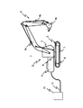
図1は本発明による作業車の状態表示装置を備えた作業車両を示す概略側面図であって、一例として、電動式のショベルを示しており、1はこの実施形態のショベル、2は上部旋回体、3は下部走行体、4は運転室、5はリンク機構(フロント)、5aはブース、5bはアーム、5cはバケット、6は旋回輪、7は走行履帯、8は走行モータ、9はバッテリ、10は外部電源、11は電力ケーブルである。
FIG. 1 is a schematic side view showing a work vehicle equipped with a work vehicle status display device according to the present invention. As an example, an electric excavator is shown, where 1 is an excavator of this embodiment and 2 is an upper turn. Body, 3 is a lower traveling body, 4 is a cab, 5 is a link mechanism (front), 5a is a booth, 5b is an arm, 5c is a bucket, 6 is a turning wheel, 7 is a traveling track, 8 is a traveling motor, 9 is A
以下では、作業車両をショベルを例に説明するが、本発明はこれに限るものではない。 Below, although an excavator is demonstrated to an example for a working vehicle, this invention is not limited to this.
図1において、ショベル1は、下部走行体3とその上に旋回輪6によって旋回可能に取り付けられた上部旋回体2とで構成されている。上部旋回体2には、オペレータが作業のための操作を行なう各種スイッチや作業(即ち、走行,旋回,リンク機構5の駆動)用の操作レバー,ロックレバーなどの操作部材やショベル1の状態などを表示する後述の表示装置などが設けられた運転室4と、この運転室4でのオペレータの操作によって掘削などの作業を行なうリンク機構5とが設けられている。
In FIG. 1, an
このリンク機構5は、上部旋回体2に設けられた回転軸(図示せず)に取り付けられて垂直な面内で回転可能なブーム5aと、このブーム5aの先端部に設けられた回転軸に取り付けられて垂直な面内で回転可能なアーム5bと、このアーム5bの先端部に設けられた回転軸に取り付けられて垂直な面内で回転可能なバケット5cとからなり、これらブーム5a,アーム5b及びバケット5cが図示しないアクチュエータの駆動によって回転動作し、所定の作業が行なわれる。
The
上部旋回体2には、旋回モータ(図示せず)が設けられており、運転室4での操作によってこの旋回モータを駆動することにより、旋回輪6が回転し、上部旋回体2が下部走行体3上で回転する。また、下部走行体3には、走行履帯7とこれを駆動する走行モータ8が設けられている。なお、下部走行体3の図示とは反対側にも、図示しないが、同様の走行履帯7と走行モータ8とが設けられている。運転室4での操作によって走行モータ8が動作し、これによって走行履帯7が駆動されることにより、下部走行体3、従って、ショベル1が前進あるいは後退などの走行動作をする。
The
上部旋回体2には、また、バッテリ9が搭載されており、旋回輪6を駆動する旋回モータや走行モータ8,リンク機構5でのアクチュエータに圧油を供給して駆動するための油圧ポンプのモータ(油圧モータ)などのための電源として用いられる。
The upper revolving
上部旋回体2には、さらに、図示しないが、後述の充電装置と外部電源接続口とが設けられており、この外部電源接続口に電力ケーブル11を接続することにより、外部電源10をこの充電装置に接続できる。そこで、この電力ケーブル11、従って、外部電源10がショベル1の上部旋回体2に着脱可能であって、電力ケーブル11が接続されたときには、充電装置を介して、バッテリ9が外部電源10によって充電可能となる。
Although not shown, the
図2は図1におけるショベル1に設けられた制御システムの一具体例を示す構成図であって、8Lは左走行モータ、8Rは右走行モータ、12は制御装置、12aは制御処理部、12bは記憶部、12cは演算処理部、12dは画像処理部、12eはタイマ、13は外部電源接続口、14は充電装置、15a,15bは開閉スイッチ、16,17,18L,18Rはインバータ、19はリンク機構5(図1)の駆動モータ、20は旋回モータ、21は油圧ポンプ、22は状態表示装置であり、図1に対応する部分には同一符号を付けて重複する説明を省略する。
FIG. 2 is a block diagram showing a specific example of the control system provided in the
同図において、後述する制御処理部12aや記憶部12b,演算処理部12c,画像処理部12d,タイマ12eなどからなる制御装置12や運転室4(図1)内に設けられた操作部(図示せず)の各種スイッチ,各種操作レバー,ロックレバーに、図示しない補助電源(制御装置用電源)から、例えば、24Vの補助電源電圧Vsが供給されている。
In the figure, a
操作部でのキー穴に挿入された起動キーの状態に応じて、図示しないキースイッチはOFF,ON,STARTのいずれかの状態にある。起動キーが単にキー穴に差し込まれただけの状態にあるときには、キースイッチはOFF状態にあり、起動キーを操作しない限り、このOFF状態がそのまま維持される。このキースイッチのOFF状態で起動キーを廻すと、キースイッチはOFF状態からON状態に移る。この場合も、起動キーを操作しない限り、このON状態がそのまま維持される。キースイッチのON状態で起動キーをさらにOFF状態からON状態にしたのと同じ方向に廻すと、キースイッチはON状態からSTART状態に移る。この場合、一般のエンジン起動キーのキースイッチと同様、このSTART状態で起動キーから手を離すと、キースイッチは自動的にON状態に戻り、起動キーもキースイッチがON状態にあるときの状態まで自動的に廻って戻る。 A key switch (not shown) is in one of OFF, ON, and START depending on the state of the activation key inserted into the key hole in the operation unit. When the activation key is simply inserted into the keyhole, the key switch is in the OFF state, and this OFF state is maintained as it is unless the activation key is operated. When the start key is turned with the key switch in the OFF state, the key switch changes from the OFF state to the ON state. Also in this case, this ON state is maintained as it is unless the activation key is operated. When the activation key is further turned in the same direction as the key switch is turned from the OFF state to the ON state in the ON state of the key switch, the key switch moves from the ON state to the START state. In this case, as with a general engine start key switch, when the start key is released in this START state, the key switch automatically returns to the ON state, and the start key is also in the state when the key switch is in the ON state. It will automatically turn around and return.
操作部でのキー穴に起動キーを挿入して廻し、キースイッチをOFF状態からON状態にすると、画面切換信号SD4が制御装置12に供給され、これにより、制御装置12は状態表示装置22に補助電源電圧Vsを供給してそれを可動状態にする。そして、キースイッチがON状態にあるときに、起動キーを廻してキースイッチをSTART状態にすると、キースイッチ信号SD1が制御装置12に供給される。これにより、制御装置12は切換制御信号SC1を開閉スイッチ15aに送り、これをON(閉じた)状態にする。この開閉スイッチ15aがON状態にあるときには、バッテリ9からの、例えば、300Vの高圧の直流電源電圧が開閉スイッチ15aを介して各インバータ16,17,18L,18Rに供給され、操作レバーを操作することによってショベル1が作業可能な可動状態となる。この状態で起動キーから手を離してキースイッチがON状態となっても、かかる可動状態がそのまま維持される。また、かかる可動状態で、起動キーの操作により、キースイッチをON状態からOFF状態にすると、キースイッチ信号SD1が供給されなくなり、これとともに、制御装置12は開閉スイッチ15aに切換制御信号SC1を送り、これをOFF(開いた)状態にする。これにより、各インバータ16,17,18L,18Rへの電力の供給がなくなり、操作レバーを操作してもショベル1の作業が行なわれない停止状態となる。
When the activation key is inserted into the keyhole in the operation unit and turned to turn the key switch from the OFF state to the ON state, the screen switching signal SD4 is supplied to the
ショベル1が可動状態にあって、作業用の操作レバー(以下、単に操作レバーという)が操作されると、操作レバーの操作量に応じたレバー操作量信号SD2が制御装置12に供給される。これにより、制御装置12は、操作レバーの夫々に該当するインバータ16,17あるいは18L,18Rに指令信号SC3を送り、その操作量に応じた動作をさせる。また、ロックレバーが操作されると、ロックレバー信号SD3が制御装置12に供給され、制御装置12は切換制御信号SC1を開閉スイッチ15aに送り、これをOFF状態にする。これにより、キースイッチがON状態にある可動状態にありながら、ショベル1は操作レバーを操作しても動作(作業)しないロック状態になる。
When the
なお、インバータ16や駆動モータ19,油圧ポンプ,図示しないアクチュエータなどのリンク機構5を動作させるためのシステムを、以下、油圧系といい、インバータ17や旋回モータ20などの上部旋回体2を旋回させるためのシステムを、以下、旋回系といい、インバータ18L,18Rや走行モータ8L,8Rなどの下部走行体3を走行させるためのシステムを、以下、走行系という。また、これらの系を総称して駆動系という。
A system for operating the
インバータ16,17,18L,18Rは、バッテリ4からの直流電源電圧を交流電圧に変換し、これに接続された駆動モータ19,20,8L,8Rの交流電源電圧を作成するものであって、制御装置12からの指令信号SC3に応じて、動作がON,OFF制御されるとともに、操作レバーの操作量に応じて交流電源電圧のデューティ比や極性が制御される。これにより、これら駆動モータ19,20,8L,8Rの回転速度や回転方向が制御される。駆動モータ19の回転速度や回転方向に応じて油圧ポンプ21が圧油を図示しないアクチュエータに送り、これにより、リンク機構5(図1)がその駆動用の操作レバーの操作に応じた動作をする。また、旋回モータ20の回転速度に応じた速度で回転方向に応じた方向に旋回輪6(図1)が回転し、これにより、旋回用の操作レバーの操作に応じて上部旋回体2(図1)が旋回動作をする。また、左走行モータ8Lと右走行モータ8Rとの回転速度と回転方向とにより、下部走行体(図1)、従って、ショベル1が走行用の操作レバーの操作に応じた速度で前進もしくは後進する。また、ロックレバーが操作されると、上記のように、ロックレバー信号SD3によって制御装置12が切換制御信号SC1を発生し、これにより、開閉スイッチ15aがOFF状態になってショベル1がロック状態となる。
The
ここで、駆動モータ19は、油圧ポンプ21を駆動するものであるが、この油圧ポンプ21は、図1に示すショベル1のリンク機構5でのブーム5aを動作させるためのアクチュエータに圧油を供給する油圧ポンプと、同じくアーム5bを動作させるためのアクチュエータに圧油を供給する油圧ポンプと、同じくバケット5cを動作させるためのアクチュエータに圧油を供給する油圧ポンプとをまとめて示すものであり、従って、駆動モータ19やインバータ17も、これら油圧ポンプ毎の駆動モータやインバータをまとめて示すものである。
Here, the
ここで、ショベル1の上部旋回体2(図1)の後部には、電力ケーブル11が着脱可能な外部電源接続口13とこれに接続された充電装置14とが設けられており、外部電源10からの電力ケーブル11がこの外部電源接続口13に接続されると、この外部電源10から電力ケーブル11を介して充電装置14に交流電圧が供給され、ここで直流電圧に変換されて、開閉スイッチ15bを介し、バッテリ9に供給される。これにより、バッテリ9が充電される。この開閉スイッチ15bは制御装置12からの切替制御信号SC2によってON,OFF(開閉)制御される。また、電力ケーブル11が外部電源接続口13に接続され、充電装置14に外部電源10から交流電圧が供給されて充電用の直流電圧が生成されると、充電装置14はこれを検出して、電力ケーブル11が外部電源接続口13、従って、ショベル1に接続されたことを示す外部電力接続信号DSを発生し、制御装置12に供給する。
Here, the rear part of the upper swing body 2 (FIG. 1) of the
制御装置12は、この充電装置14からの外部電源接続信号DSを取り込み、外部電源接続口13に電力ケーブル11が接続されたか否かを常時監視しており、外部電源接続口13に電力ケーブル11が接続されると、切換制御信号SC2を発生して開閉スイッチ15bをON(閉じた)状態にする。これにより、外部電源接続口13に電力ケーブル11を接続すると、充電装置14によって自動的にバッテリ9の充電が行なわれる。
The
また、制御装置12は、常時バッテリ9のバッテリ残量DBを検出しており、バッテリ9の充電量が満杯(100%のバッテリ残量)になったことを検出すると、切替制御信号SC2を発生して、開閉スイッチ15bをOFF(開いた)状態にする。これにより、バッテリ9の充電が自動的に終了する。電力ケーブル11を外部電源接続口13から取り外したときにも、制御装置12は切替制御信号SC2を発生し、開閉スイッチ15bをOFF状態にする。なお、ショベル1がいかなる状態にあっても、電力ケーブル11が外部電源接続口13に接続されているときには、バッテリ9のバッテリ残量が次第に低減して規定のバッテリ残量(以下、充電開始レベルといい、例えば、満杯の90%のバッテリ残量)未満になると、充電装置14からバッテリ9に充電が開始され、満杯となるまで充電が行なわれる。
Further, the
図3は以上のショベル1の状態とこれらの関係を示す図であって、S0は停止状態、S1は可動状態、S2は充電状態、S3は可動/充電状態である。
FIG. 3 is a diagram showing the state of the
同図において、停止状態S0は、上記のように、キースイッチがOFF状態にあり、図2での開閉スイッチ15aがOFF状態にあって、インバータ16,17,18L,18Rに電力が供給されていない状態である。但し、状態表示装置22(図2)は、補助電源電圧が供給されて可動状態にある。
In the figure, in the stop state S0, as described above, the key switch is in the OFF state, the open /
かかる停止状態S0で起動キーを廻してキースイッチをSTART状態に保持することにより、キースイッチ信号SD1(図2)がスタートすると、上記のように、開閉スイッチ15aがON状態となり、油圧系,旋回系及び走行系にバッテリから電力が供給されて、操作レバーの操作によるショベル1の作業動作が可能な可動状態S1となる。可動状態を確認して起動キーから手を離すと、キースイッチはSTART状態からON状態に戻る。また、かかる可動状態S1でキースイッチをOFF状態に戻すと、停止状態S0に戻ることになる。
When the key switch signal SD1 (FIG. 2) is started by turning the start key in the stop state S0 and holding the key switch in the START state, the open /
この可動状態S1は電力ケーブル11が外部電源接続口13(図2)に接続されていない状態をいうものであるが、停止状態S0で電力ケーブル11を外部電源接続口13に接続すると、バッテリ9が外部電源10から充電装置14を介して充電される充電状態S2となる。この場合、上記のように、バッテリ9のバッテリ残量が上記の充電開始レベル以上であるときには、開閉スイッチ15bがOFF状態に保持され、充電は行なわれない。この充電状態S2は、キースイッチがOFF状態にあって、開閉スイッチ15aがOFF状態にあるものであって、かかる充電状態S2で電力ケーブル11を外部電源接続口13から取り外すと、充電状態S2が解除されて停止状態S0に戻る。これとともに、ON状態にあった開閉スイッチ15bは、制御装置12からの切換制御信号SC2により、自動的にOFF状態となる。
This movable state S1 is a state in which the
可動状態S1にあるときに電力ケーブル11を外部電源接続口13に接続すると、あるいは、充電状態S2にあるときに起動キーを廻して、キースイッチをSTART状態に保持すると、バッテリ9を充電しながら、油圧系,旋回系及び走行系にバッテリ9から電力が供給され、操作レバーの操作によるショベル1の作業動作が可能な可動/充電状態S3となる。
When the
ところで、以上の停止状態S0,可動状態S1,充電状態S2,可動/充電状態S3を総称して通常状態Sということにするが、かかる通常状態Sでロックレバーをロック操作すると、上記のように、開閉スイッチ15a(図2)がOFF状態となって各インバータ16,17,18L,18Rへの(従って、油圧系,旋回系及び走行系への)バッテリ9からの電力供給が遮断された状態に保持されるロック状態S4となり、ショベル1の駆動部の駆動が禁止される。また、かかるロック状態S4でロックレバーをアンロック操作すると、通常状態Sに戻る。
By the way, the stop state S0, the movable state S1, the charge state S2, and the movable / charge state S3 are collectively referred to as a normal state S. When the lock lever is operated to lock in the normal state S, as described above. When the open /
ここで、ロックレバーは、オペレータが運転室4(図1)に乗り降りする場所に設けられており、アンロックされた状態では、この乗り降りができない状態になっている。このため、オペレータが運転室4に乗り降りするときには、ロックレバーをロック操作をして乗り降りの邪魔にならないようにする。これにより、ショベル1が通常状態Sにあっても、即ち、停止状態S0,可動状態S1,充電状態S2,可動/充電状態S3のいずれの状態にあっても、オペレータが運転室4から降りるときには、必ずロックレバーがロック操作され、これによってロック状態S4となる。オペレータが運転室4に乗るときには、ロックレバーがロック操作された状態にあるので、そのまま乗ることができ、このときロック状態S4が保持されるが、ロックレバーをアンロック操作することにより、通常状態Sにすることができる。
Here, the lock lever is provided at a place where the operator gets on and off the cab 4 (FIG. 1), and when unlocked, the lock lever cannot be used. For this reason, when the operator gets in and out of the
なお、ロック状態S4にあっても、上記のように、キースイッチをOFF状態からON状態にしたときには、画面切換信号SD4が制御装置12に供給され、これによって状態表示装置22が可動状態となる。
Even in the locked state S4, as described above, when the key switch is changed from the OFF state to the ON state, the screen switching signal SD4 is supplied to the
また、ロック状態S4になる直前の通常状態Sとロック状態S4の解除直後の通常状態Sとが異なることもある。例えば、オペレータが停止状態S1でロックレバーのロック操作をしてロック状態S4とし、運転室4から降りて電力ケーブル11を外部電源接続口13に接続し、しかる後、運転室4に戻ってロックレバーをアンロック操作すると、ロック状態S4が解除されて充電状態S2となる。
Further, the normal state S immediately before entering the locked state S4 may be different from the normal state S immediately after releasing the locked state S4. For example, the operator operates the lock lever in the stop state S1 to enter the lock state S4, gets out of the
以上の構成のショベル1において、運転室4内に設けられた状態表示装置22(図2)は、このショベル1の状態を表示するものであって(但し、かかる状態以外の画像表示も可能である)、かかる状態表示装置22の第1の実施形態について説明する。
In the
図2において、制御装置12は、上記各種の入力信号SD1〜SD3や外部電源接続信号DSに応じてショベル1の状態S1〜S4(図3)を判定し、切換制御信号SC1,SC3や指示制御信号SC3などを発生する制御処理部12a,状態表示装置22に表示する画像情報などを記憶した記憶部12b,バッテリ9のバッテリ残量DBを検出して演算処理などを行なう演算処理部12c,記憶部12bから読み出した画像情報や演算処理部12cでの処理結果を状態表示装置22に表示させるために処理する画像処理部12d,時間計測のためのタイマ12eなどを備えており、入力信号SD1〜SD3や外部電源接続信号DSから制御処理部12aで判定される状態に応じた画像情報を記憶部12bから読み取り、これと演算処理部12cの処理結果とを画像処理部12dで処理して状態表示装置22の表示画面に表示させる。
In FIG. 2, the
これにより、図3に示す状態S1〜S4毎に、その状態を表わす画面(状態画面)が表示されるが、以下、その具体例について説明する。 As a result, a screen (state screen) representing the state is displayed for each of the states S1 to S4 shown in FIG. 3, and specific examples thereof will be described below.
図4は本発明による作業車両の情報表示装置の一実施形態での停止状態S0であるときの状態表示画面の一具体例を示す図であり、23aは状態表示画面、24はバッテリインジケータ(指示画像)、24aはバッテリ残量インジケータ、24bは警報レベル、25はバッテリ残量値表示エリア、26はバッテリ使用可能時間表示エリア、27は使用電源表示エリア、27aはバッテリ使用表示エリア、27bは外部電源使用表示エリアである。 FIG. 4 is a diagram showing a specific example of the status display screen when the stop state S0 in the embodiment of the information display apparatus for work vehicles according to the present invention is shown, in which 23a is a status display screen and 24 is a battery indicator (instruction). Image), 24a is a remaining battery indicator, 24b is an alarm level, 25 is a remaining battery value display area, 26 is a battery usable time display area, 27 is a power usage display area, 27a is a battery usage display area, and 27b is external This is the power usage display area.
同図において、停止状態S0では、状態表示装置22の表示画面には、バッテリインジケータ24やバッテリ残量値表示エリア25,バッテリ使用可能時間表示エリア26,使用電源表示エリア27からなる状態表示画面23aが表示される。
In the figure, in the stop state S0, the display screen of the
バッテリ9を表わすインジケータ24は縦長の矩形状の枠で表示され、この枠内にバッテリ9(図2)の現時点でのバッテリ残量を表わすバッテリ残量インジケータ24aがバッテリインジケータ24の下辺からの深さでもって表わされる。また、このバッテリインジケータ24には、警報レベル24bが設けられている。このバッテリ残量インジケータ24aは、バッテリ9の検出されるバッテリ残量値を演算処理部12cで演算処理することによって得られるものであって、バッテリ残量が100%(即ち、満杯)であるとき、バッテリインジケータ24全体がバッテリ残量インジケータ24aとなり、記憶部12bから読み出されたバッテリインジケータ24と警報レベル24bにこの演算処理結果が合成されることによって表示される。
The
なお、バッテリ残量インジケータ24aのレベルが警報レベル24b以下となると、外部電源10(図2)から充電がなされていない停止状態S0や可動状態S1では、図示しないが、状態表示画面23aに警報画面が表示されるとともに、警報が発せられる。
When the level of the remaining
バッテリ残量値表示エリア25には、バッテリ9の現時点でのバッテリ残量が数値(%)で表示され、バッテリ使用可能時間表示エリア26には、現時点からこのときの状態でバッテリ9を電源として使用した場合のバッテリ残量が警報レベル24bに達するまでの時間(h)を表わすものである。これら現時点でのバッテリ残量やバッテリ使用可能時間は演算処理部12cの演算処理によって得られ、これらがバッテリ残量値表示エリア25やバッテリ使用可能時間表示エリア26に重畳されて表示される。ここでは、バッテリ残量表示エリア25にバッテリ残量が「83%」と表示され、バッテリ使用可能時間表示エリア26にバッテリ使用可能時間が「3.4h(3.4時間)」と表示されている状態を示す。この場合には、バッテリインジケータ24のバッテリ残量インジケータ24aは、バッテリ残量が「83%」である状態を示している。
The battery remaining
ここで、バッテリ使用可能時間表示エリア26に表示されるバッテリ使用可能時間は、現時点での電力消費速度で電力を消費した場合の現時点からバッテリ残量が警報レベル24bになるまでの時間を表わすものであり、タイマ12e(図2)によって時間計測し、所定時間(例えば、30分間)毎にこの所定時間でのバッテリ9の電力消費速度の平均と現時点での電力消費速度とを基に求めるものである。ここで、電力消費速度は単位時間当たりの電力消費量である。
Here, the battery usable time displayed in the battery usable
いま、上記所定時間をTsとして、現時点をt0、これより所定時間Ts前の時点をt-1、この時点t-1より所定時間Ts前の時点をt-2とする。ここで、時点t-2から時点t-1までの平均電力消費速度をV-1とすると、この時点t-1でのバッテリ使用可能時間T-1は、この時点t-1からこの平均電力消費速度V-1でバッテリ9の電力(バッテリ残量)Pを警報レベル24bまで消費するに要する時間を表わすものである。従って、
T-1=P/V-1 ……(1)
である。
Now, the predetermined time as Ts, the current t 0, than this a point before the predetermined time Ts t -1, a time point before the predetermined time Ts from the time point t -1 and t -2. Here, if the average power consumption rate from time t -2 to time t -1 and V -1, battery available time T -1 at this point t -1, this average power from the time t -1 This represents the time required to consume the power (remaining battery power) P of the battery 9 up to the
T −1 = P / V −1 (1)
It is.
また、時点t-1から現時点t0までの期間でのバッテリ9の電力消費量をΔPとし、この期間での平均電力消費速度をV0とすると、
ΔP=Ts・V0 ……(2)
であり、この平均電力消費速度V0を現時点での電力消費速度として、現時点t0から電力消費速度V0でバッテリ9の電力を警報レベル24bまで消費するのに要する時間、即ち、現時点t0でのバッテリ使用可能時間T0は、このときのバッテリ残量を(P−ΔP)として、
T0=(P−ΔP)/V0 ……(3)
となり、これら式(1)〜(3)により、
T0=(T-1・V-1/V0)−Ts ……(4)
となる。
Further, if the power consumption of the battery 9 in the period from the time t −1 to the current t 0 is ΔP, and the average power consumption speed in this period is V 0 ,
ΔP = Ts · V 0 (2)
With this average power consumption speed V 0 as the current power consumption speed, the time required to consume the power of the battery 9 from the current time t 0 to the
T 0 = (P−ΔP) / V 0 (3)
From these formulas (1) to (3),
T 0 = (T −1 · V −1 / V 0 ) −Ts (4)
It becomes.
但し、バッテリ9の電力を消費しない期間(V0=0)では、タイマ12e(図2)の動作も停止して時間計測せず、上記の計算に入れない。所定時間Tsは、実際にバッテリ9の電力が消費される時間であり、途中でショベル1の動作が停止して一時電力の消費がない場合には、タイマ12eも時間計測を中止して所定時間Tsを計測しない。
However, in a period (V 0 = 0) in which the power of the battery 9 is not consumed, the operation of the
ここで、上記式(4)での右辺第1項は、バッテリ残量がPのときに電力消費速度V-1で消費したときのバッテリ使用可能時間T-1を電力消費速度V0で消費したときの時間に変換したものであり、これから所定時間Tsを差し引くことにより、現時点t0でのバッテリ使用可能時間T0が求められる。 Here, the first term on the right side in the above equation (4) is that the battery usable time T −1 when consumed at the power consumption speed V −1 when the remaining battery capacity is P is consumed at the power consumption speed V 0 . It is obtained by converting the time when, by now subtracting the predetermined time Ts, the battery available time T 0 at the present time t 0 is determined.
なお、以上のようにして求められたバッテリ残量(P−ΔP)、電力消費速度V0,V-1、バッテリ使用可能時間T0が制御装置12の記憶部12bに格納される。即ち、所定時間Ts毎に求められてこれらの情報は、記憶部12bに記憶されることにより、1回前に求められて記憶されたかかる情報を更新する。従って、キースイッチがOFF状態となって全ての電源がOFF状態になっても、上記の情報はそのまま記憶部12bに保存されることになり、次に、キースイッチをON状態にして停止状態S0にしたときには、初期表示として、上記の記憶部12bに保存されている情報が用いられる。初期状態S0での状態表示画面23aでは、かかる情報を用いて求められたバッテリ使用可能時間が表示される。後述の図5に示す可動状態S1での状態表示画面23b2,23b3では、上記の式(4)に基づいて計算されたバッテリ使用可能時間T0が表示されることになる。
Note that the remaining battery level (P−ΔP), the power consumption speeds V 0 and V −1 , and the battery usable time T 0 obtained as described above are stored in the storage unit 12 b of the
ここで、所定時間Tsを、例えば、30分間としたが、これよりも長くても、短くてもよい。所定時間Tsを、例えば、1分間とした場合には、この場合でも、上記と同様であって、1分毎にバッテリ9の消費電力量ΔPが求められて1分間での平均電力消費速度が求められ、上記式(4)により、リアルタイムで現時点T0でのバッテリ使用可能時間T0が求められてバッテリ使用可能時間表示エリア26で表示される。
Here, the predetermined time Ts is, for example, 30 minutes, but it may be longer or shorter than this. In the case where the predetermined time Ts is, for example, 1 minute, in this case as well, the power consumption amount ΔP of the battery 9 is obtained every minute and the average power consumption rate per minute is obtained. sought, the above equation (4), the battery available time T 0 at the moment T 0 in real time is displayed in the battery usable
また、新しいショベル1を最初に使用するときには、バッテリ9に充電が行なわれるが、このときには、記憶部12bには、上記の情報は記憶されていない。このために、記憶部12bには、別の電力消費速度の初期値が格納されており、充電量(バッテリ残量)が警報レベル24c以上となると(それまでは、バッテリ使用可能時間=0h)、上記式(1)により、この電力消費速度の初期値を電力消費速度V-1として、バッテリ残量DB(図2)で計測されるバッテリ残量Pとから、上記最初のバッテリ使用可能時間Tを求める。
When the
使用電源表示エリア27は、インバータ16,17,18L,18Rに電力を供給している電源を表わすものであって、バッテリ表示エリア27aと外部電源表示エリア27bとからなっている。バッテリ9が電源として使用されるときには、バッテリ表示エリア27aが点灯表示され、外部電源11が電源として使用されるときには、外部電源表示エリア27bが点灯表示される。
The power
この停止状態S0では、開閉スイッチ15a(図2)がOFF状態にあって、インバータ16,17,18L,18Rに電力が供給されていない状態にあるので、電力の消費はなく、また、電力ケーブル11も外部電源接続口13に接続されていないので、バッテリ9のバッテリ残量はそのまま「83%」に保持される。また、バッテリ使用可能時間表示エリア26は、過去の最新の可動状態S1,充電状態S2または可動/充電状態S3のときの使用可能時間画面のまま表示される。さらに、使用電源表示エリア27でのバッテリ表示エリア27a,外部電源表示エリア27bは、いずれも点灯表示されていない。
In this stop state S0, since the open /
通常の建設機械では、起動キー(エンジンキー)をSTART状態にすることによってエンジンが起動し、このエンジンの稼働音により、聴覚によって可動状態を把握することができるが、電動式の建設機械では、稼働音が著しく低いため、運転者は操作している建設機械が停止状態にあるのか、可動状態にあるかを聴覚によって把握することが困難である。 In a normal construction machine, the engine is started by setting the start key (engine key) to the START state, and the moving state can be grasped by hearing with the operating sound of the engine. However, in the electric construction machine, Since the operating noise is remarkably low, it is difficult for the driver to grasp by hearing whether the construction machine being operated is in a stopped state or in a movable state.
この実施形態では、停止状態S0では、状態表示装置22にバッテリ9あるいは外部電源10のいずれからも電力が供給されていない表示を行なうものであるから、視覚によってその状態を容易に把握することができる。
In this embodiment, in the stop state S0, the
また、状態表示装置22では、バッテリインジケータ24でバッテリ残量を帯状に表現し、どの程度使用したかの相対的な量として直感的に知らせる表示と、残量を総量100とした場合の割合を示す数値と、使用可能な予測時間という数値の絶対的な量として表示することにより、従来の液体の燃料に比べてエネルギーを量としてわかりづらいことを、相対的な表示と絶対的な表示とを同時に表示することにより、オペレータに視覚的に瞬時に残量を把握しやすく表示できる。
Further, in the
なお、停止状態S0では、キースイッチをOFF状態からON状態に切り換えることにより、図4に示す状態表示画面23aが表示されるが、タイマ12eの時間計測によって予め決められた時間(<Ts)が経過すると、表示を終了するようにして電力消費の低減を図ることもできる。再度表示させるためには、操作部でそのための操作ボタンを設けるようにしてもよいし、また、キースイッチを再度OFF状態からON状態にすることによって再表示されるようにしてもよい。また、後述の他の状態S1〜S4においても、同様である。
In the stop state S0, the
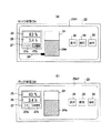
図5は本発明による作業車両の情報表示装置の一実施形態での可動状態S1であるときの状態表示画面の一具体例を示す図であって、23b1〜23b3は状態表示画面、28は走行系インジケータ、29は旋回系インジケータ、30は油圧系インジケータ、31は電力供給ラインインジケータ、32は電力回生ラインインジケータであり、図4に対応する部分には同一符号をつけて重複する説明を省略する。 FIG. 5 is a diagram showing a specific example of the state display screen when the movable vehicle is in the movable state S1 in the embodiment of the information display device for a work vehicle according to the present invention, in which 23b1 to 23b3 are the state display screens, and 28 is the traveling The system indicator, 29 is a turning system indicator, 30 is a hydraulic system indicator, 31 is a power supply line indicator, 32 is a power regeneration line indicator, and parts corresponding to those in FIG. .
図5(a)は操作レバーが操作されないで電力消費がない(即ち、無電力消費の)可動状態S1の状態表示画面23b1を示すものであって、かかる無電力消費の可動状態S1は、先に説明したように、キースイッチをSTART状態にすることにより、開閉スイッチ15aがON状態となり、バッテリ9からインバータ16,17,18L,18Rに電力が供給される状態である。かかる無電力消費の可動状態S1では、図2でのインバータ18L,18Rと走行モータ8L,8Rなどからなる走行系を表わす走行系インジケータ28と、同じくインバータ17と旋回モータ20などからなる旋回系を表わす旋回系インジケータ29と、同じくインバータ17や駆動モータ19,油圧ポンプ21などからなる油圧系を表わす油圧系インジケータ30とが表示され、開閉スイッチ15aがON状態にあることから、バッテリインジケータ24から走行系インジケータ28,旋回系インジケータ29及び油圧系インジケータ30にわたる電力供給ライン31が表示され、走行系インジケータ28,旋回系インジケータ29及び油圧系インジケータ30から電力供給ライン31にわたる電力回生ライン32が表示される。
FIG. 5A shows a state display screen 23b1 in the movable state S1 in which the operation lever is not operated and there is no power consumption (that is, no power consumption). As described above, when the key switch is set to the START state, the open /
ここで、バッテリ9から電力供給が行なわれていることを表わす電力供給ラインインジケータ31は電力源(この場合、バッテリインジケータ24)から電力が供給されていることを表わし、電力回生ラインインジケータ32はモータ8L,8R,20,21で誘起される電力が電力源に回生されていることを表わすものである。電力回生時には、電力の供給方向が電力の消費時とは逆方向であり、バッテリ9に電力が供給されて充電が行なわれるものであるから、バッテリ9での電力消費を減少させる。この電力回生が行なわれるときには、上記式(2),(3)における電力消費量ΔPは、バッテリ9から走行系や旋回系,油圧系に供給される電力量(電力消費量)から電力回生量を差し引いたものであるが、これは、現時点T0でのバッテリ残量Pとこれより所定時間Ts前でのバッテリ残量Pとの差にほかならない。
Here, the power
また、使用電源表示エリア27では、バッテリ9を電力供給源とするものであるから、バッテリ表示エリア27aが点灯表示する。この無電力消費の可動状態S0では、バッテリ9の電力消費がないから、バッテリ残量インジケータ24aに変化はないし、バッテリ残量表示エリア25やバッテリ使用可能時間表示エリア26の表示内容も変化しない。
In addition, since the power
ここで、図3における可動状態S1及び可動/充電状態S3では、走行系や旋回系,油圧系を稼働させるために、これらの駆動系で使用できる電力量の上限値を切り換える電力使用モードがある。この実施形態では、この電力使用モードとして、使用できる電力量の上限値を上限値を設定して低消費電力に制限を加えたEモード(エコモード)と、消費電力の制限をしないPモード(パワーモード)とがある。 Here, in the movable state S1 and the movable / charge state S3 in FIG. 3, in order to operate the traveling system, the turning system, and the hydraulic system, there is a power usage mode that switches the upper limit value of the amount of power that can be used in these drive systems. . In this embodiment, as this power usage mode, an E mode (eco mode) in which an upper limit value of the amount of power that can be used is set and an upper limit value is set to limit the low power consumption, and a P mode (no power consumption limitation) Power mode).
図5(b)は低消費電力に制限したEモードで操作レバーが操作され、作業が行なわれるときの可動状態S1の状態表示画面23b2を示すものであって、操作レバーの操作によってインバータ16,17,18L,18Rから駆動モータ19,20,8L,8Rに電力が供給されるようになると、電力供給ラインインジケータ31に電力の流れを示す1つの細いバー列の流れが表示される。また、図示しないが、また、走行系インジケータ28,旋回系インジケータ29あるいは油圧系インジケータ30で電力の供給が終わったとき、駆動モータ19,20,8L,8Rでその回転によって電力が誘起され、これが電力源であるバッテリ9に回生されるときには、走行系インジケータ28,旋回系インジケータ29もしくは油圧系インジケータ30から電力回生ラインに沿ってバッテリインジケータ24に細いバー列33が移動して表示される。
FIG. 5 (b) shows a state display screen 23b2 in the movable state S1 when the operation lever is operated in the E mode limited to low power consumption and the work is performed. When power is supplied to the
図5(c)は消費電力に制限を加えないPモードで操作レバーが操作され、作業が行なわれるときの可動状態S1の状態表示画面23b3を示すものであって、この場合には、電力供給ラインインジケータ31がEモードの場合の図5(b)に示す電力供給ラインインジケータ31に比べて太い電力供給ラインインジケータ31が表示され、操作レバーの操作によってインバータ16,17,18L,18Rから駆動モータ19,20,8L,8Rに電力が供給されるようになると、電力供給ラインインジケータ31に電力の流れを示す2つの細いバー列33の流れが表示される。これ以外にの点については、図5(b)に示す状態表示画面23b2と同様である。
FIG. 5C shows the state display screen 23b3 in the movable state S1 when the operation lever is operated and the work is performed in the P mode that does not limit power consumption. In this case, power supply is performed. A power
Eモードで操作レバーの操作が行なわれる可動状態S1での図5(b)に示す状態表示画面23b2とPモードで操作レバーの操作が行なわれる図5(c)に示す状態表示画面23b3とでは、バッテリ9からの電力消費があるから、バッテリインジケータ24でのバッテリ残量インジケータ24aが減少し、バッテリ残量表示エリア25でのバッテリ残量値やバッテリ使用可能時間表示エリア26でのバッテリ使用可能時間が減少する。但し、その減少の速度は、図5(c)に示す状態表示画面23b3の場合の方が速い。なお、EモードやPモードの可動状態S1から操作レバーの操作が行なわれない無消費電力の可動状態S1に移ると、タイマ12e(図2)が停止されて時間計測は行なわれず、無消費電力の可動状態S1にある期間はバッテリ使用可能時間の計算に用いられない。
In the movable state S1 where the operation lever is operated in the E mode, the state display screen 23b2 shown in FIG. 5B and in the state display screen 23b3 shown in FIG. 5C where the operation lever is operated in the P mode, Since there is power consumption from the battery 9, the remaining
なお、電力の流れを示す細いバー33は、Eモードでは、1列で示し(図5(b))、Pモードでは、2列で示す(図5(c))ことを説明したが、速度制限ダイアルでの制御では、図示しないが、電力の流れを示す細いバー33の流れ方が遅い状態と速い状態とで表示される。速度制限ダイアルは、駆動アクチュエータの運転速度の上限を制限するダイアルであり、絞れば、上限速度が減少され、開ければ、上限速度が増加されるようになる。
Note that the
基本的にエネルギーの燃費と運転速度との関係は相反する関係であり、燃費を悪くすると、運転速度は速くなるし、逆に、運転速度を遅くすることにより、燃費が良くなる。従来の建設機械での運転速度と燃費との関係をユーザが調整する系統は、1つはEモードとPモードとの切り換え、もう1つはコンジンコントロールダイアル(速度制限ダイアル)という2系統の制御が知られている。 Basically, the relationship between the fuel consumption of energy and the driving speed is a contradictory relationship. If the fuel consumption is deteriorated, the driving speed is increased, and conversely, the fuel consumption is improved by reducing the driving speed. The system in which the user adjusts the relationship between the driving speed and the fuel consumption in the conventional construction machine is one of switching between the E mode and the P mode, and the other is a condin control dial (speed limiting dial). Control is known.
この実施形態では、かかる制御を夫々画面上で表示するものであって、EモードとPモードは、電力の流れを示す1列,2列の細いバー33で表示させ、速度制限ダイアルは、かかる1列または2列の細いバー33を、ダイアル小の場合には、ゆっくりと流れ、ダイアル大の場合には、速く流れるように表示させることにより、E,Pモードや速度制限ダイアルの異なる系統での燃費と運転速度との表示状態を直感的に認識できるようにしている。
In this embodiment, such control is displayed on the screen, and the E mode and the P mode are displayed by the
このことにより、エネルギーが多く流れて使用され、運転速度が速くなっているという状態を速度制限ダイアル表示と比較して、直感的に認識することができる。 As a result, it is possible to intuitively recognize a state in which a lot of energy flows and is used and the driving speed is high compared with the speed limit dial display.
また、従来では、運転中にエネルギーを装置が回生運動のように生産できず、消費するのみであったが、電力を使用するこの実施形態では、操作によっては、モータを逆回転させてエネルギーを生産することができる。 Further, in the past, the device could not produce the energy during the operation like a regenerative movement, but only consumed it.In this embodiment using electric power, depending on the operation, the motor can be rotated in reverse to save the energy. Can be produced.
この実施形態では、同一画面にどこで発電がなされて充電されているのかを表示させるものであるから、燃料の消費パターン(Eモード,Pモード,速度制限ダイアル)と、回生の発電元(走行,旋回,油圧)、燃料タンク(バッテリ9と外部電源10)の関係が一覧でき、エネルギーの流れがわかるようになり、回生の特性(タイミング・回生が発生するパターン)を、運転しながら、身に付けることができるので、回生運動を効果的に運転に織り交ぜることにより、燃料を節約して作業を推進できる。 In this embodiment, where the power is generated and charged is displayed on the same screen, the fuel consumption pattern (E mode, P mode, speed limit dial) and the regenerative power generation source (running, Swirling, hydraulic pressure), fuel tank (battery 9 and external power supply 10) can be listed, energy flow can be understood, regenerative characteristics (timing, regenerative pattern) while driving Therefore, it is possible to save fuel and promote the work by effectively intermingling the regenerative movement with the driving.
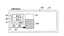
図6は本発明による作業車両の情報表示装置の一実施形態での充電状態S2であるときの状態表示画面の一具体例を示す図であって、23cは状態表示画面、34は電力ケーブルインジケータであり、図4に対応する部分には同一符号をつけて重複する説明を省略する。 FIG. 6 is a diagram showing a specific example of the state display screen when the state is the charging state S2 in the embodiment of the information display apparatus for work vehicles according to the present invention, in which 23c is a state display screen and 34 is a power cable indicator. Therefore, parts corresponding to those in FIG.
同図において、この充電状態S2での状態表示画面23cでは、電力ケーブル11を表わす電力ケーブルインジケータ34がバッテリインジケータ24に接続された状態が表示される。オペレータがショベル1の外部電源接続口13(図2)に電力ケーブル11を接続すると、制御装置12が外部電源接続信号DS(図2)からこれを検出することにより、状態表示装置22の表示画面にかかる状態表示画面23cが表示されることになる。
In the figure, the
また、このように、バッテリ9が充電されるときには、バッテリインジケータ24に警報レベル24bは表示されない。従って、バッテリインジケータ24でのバッテリ充電インジケータ24aのレベルが警報レベル24b以下となっていても、充電によってバッテリの残量が増加するので、上記の警報は出ない。
In this way, when the battery 9 is charged, the
これ以外は図4に示す停止状態S0での状態表示画面23aと同様であるが、外部電源10(図2)からバッテリ9に充電が行なわれるので、その充電量に応じてバッテリインジケータ24でのバッテリ残量インジケータ24aの表示量が増加し、バッテリ残量表示エリア25でのバッテリ残量値やバッテリ使用可能時間表示エリア26でのバッテリ使用可能時間も増加する。
Other than this, it is the same as the
この場合のバッテリ使用可能時間Tも、上記所定時間Ts毎に計測されるものである。この場合には、記憶部12bに格納されている先の電力消費速度の初期値を電力消費速度V0とし、計測されるバッテリ残量Pを用いて、上記式(1)、即ち、
T0=P/V0
により、バッテリ使用可能時間T0を求めて表示する。この場合、バッテリ残量Pが順次増加していくから、バッテリ使用可能時間T0も増加していく。
The battery usable time T in this case is also measured every the predetermined time Ts. In this case, the initial value of the previous power consumption rate stored in the storage unit 12b is set as the power consumption rate V 0, and the above formula (1), that is,
T 0 = P / V 0
Thus, the battery usable time T 0 is obtained and displayed. In this case, since the battery remaining amount P increases sequentially, the battery usable time T 0 also increases.
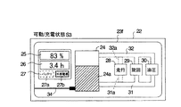
図7は本発明による作業車両の情報表示装置の一実施形態(図1に示すショベル1)での充電状態S3であるときの状態表示画面の一具体例を示す図であって、23dは状態表示画面23dであり、図4〜図6に対応する部分には同一符号をつけて重複する説明を省略する。
FIG. 7 is a view showing a specific example of the state display screen when the state is the charging state S3 in the embodiment (the
同図において、この状態表示画面23dは、図5(a)に示す可動状態S1の状態画面23b1と図6に示す充電状態S2の状態表示画面23cとを合成した画面であり、開閉スイッチ15a(図2)がON状態にあることから、走行系インジケータ28と旋回系インジケータ29と油圧系インジケータ30とが表示され、これらが電力供給ラインインジケータ31と電力回生ラインインジケータ32都によってバッテリインジケータ24に接続されて表示されている。また、電力ケーブル11が外部電源接続口13に接続されてバッテリ9の充電が行なわれていることから(図2)、電力ケーブルインジケータ34がバッテリインジケータ24に接続された状態が表示され、バッテリインジケータ24では、警報レベル24bが表示されない。この場合、充電装置14からインバータ16,17,18L,18Rに電力が供給されているものとして、使用電源表示エリア27での外部電源表示エリア27bが点灯表示される。
In this figure, this
また、この可動/充電状態S3においても、先に図5で説明した電力使用モードとしてのEモードとPモードとのいずれかが選択設定されるものであって、Eモードが設定された状態で操作レバーを操作し、作業を行なう場合には、図示しないが、図5(b)に示すように、電力供給ラインインジケータ31が細く表示されて、そこに電力の流れを示す1つの細いバー列33の流れが表示される。Eモードが設定された状態で操作レバーを操作し、作業を行なう場合には、図示しないが、図5(c)に示すように、電力供給ラインインジケータ31が太く表示されて、そこに電力の流れを示す2つの細いバー列33の流れが表示される。
Also in this movable / charge state S3, either the E mode or the P mode as the power use mode described above with reference to FIG. 5 is selected and set, and the E mode is set. When the operation lever is operated to perform work, although not shown, as shown in FIG. 5B, the power
以上のように、ショベル1の作業操作、特に、走行系の操作を行なう場合、オペレータは、ショベル1に電力ケーブル11が接続されていることが運転室4の状態表示装置22の画面により、作業室4内に居ながら自分で確認することができ、作業開始時にいちいちショベル1の後部に廻ってこれを確認したり、運転室4から他の作業員に確認して貰うといった不要な手間が省けることになり、作業をスムーズに開始させることができるし、また、作業中のかかる確認動作も不要となる。
As described above, when operating the
そして、作業開始時や作業中での確認がいつでも容易に行なえるので、ショベル1を走行させ過ぎたり、旋回させ過ぎたりして、電力ケーブル11を引張り過ぎるような事態も容易に回避できるようになる。
And since the confirmation at the start of the work or during the work can be easily performed at any time, it is possible to easily avoid the situation where the
図8(a),(b)は本発明による作業車両の情報表示装置の一実施形態(図1に示すショベル1)でのロック状態S4であるときの状態表示画面の一具体例を示す図であって、23eは状態表示画面23eであり、図4〜図7に対応する部分には同一符号をつけて重複する説明を省略する。
FIGS. 8A and 8B are diagrams showing a specific example of the state display screen when the locked state S4 in the embodiment (
図8(a)に示す状態表示画面23e1は、図7に示す可動/充電状態S3で運転室4(図1)でのロックレバーがロック操作された状態を表わしている。従って、可動状態で電力ケーブル11が外部電源接続口13(図2)に接続された状態にある。このように、可動状態にあることにより、走行系インジケータ28,旋回系インジケータ29及び油圧系インジケータ30は表示されている。
A state display screen 23e1 shown in FIG. 8A represents a state where the lock lever in the cab 4 (FIG. 1) is locked in the movable / charge state S3 shown in FIG. Therefore, the
このロック状態S4では、図3で説明したように、開閉スイッチ15a(図2)がOFF状態となっているので、インバータ16,17,18L,18Rに電力が供給されていない状態であり、このことから、電力供給ラインインジケータ31や電力回生ラインインジケータ32は表示されず、走行系インジケータ28,旋回系インジケータ29及び油圧系インジケータ30はバッテリインジケータ24に接続されていない状態で表示されている。
In the locked state S4, as described with reference to FIG. 3, since the open /
かかるロック状態S4でロックレバーをアンロック操作し、ロック状態S4を解除すると、上記のように、可動/充電状態S3となり、図7に示す状態表示画面23dに換わることになる。
When the lock lever is unlocked in the lock state S4 and the lock state S4 is released, the movable / charge state S3 is entered as described above, and the
図8(b)に示す状態表示画面23e2は、図5に示す可動状態S1で運転室4でのロックレバーがロック操作された状態を表わしている。従って、可動状態で電力ケーブル11が外部電源接続口13に接続されていない状態にある。このように、可動状態にあることにより、走行系インジケータ28,旋回系インジケータ29及び油圧系インジケータ30は表示されている。
A state display screen 23e2 shown in FIG. 8B represents a state where the lock lever in the
このロック状態S4でも、開閉スイッチ15aがOFF状態となっているので、インバータ16,17,18L,18Rに電力が供給されていない状態であり、このため、電力供給ラインインジケータ31や電力回生ラインインジケータ32は表示されず、走行系インジケータ28,旋回系インジケータ29及び油圧系インジケータ30はバッテリインジケータ24に接続されていない状態で表示されている。
Even in this locked state S4, since the open /
かかるロック状態S4でロックレバーをアンロック操作し、ロック状態S4を解除すると、上記のように、可動状態S1となり、図5に示す状態表示画面23b1〜23b3のいずれかに換わることになる。 When the lock lever is unlocked in the locked state S4 and the locked state S4 is released, the movable state S1 is entered as described above and the state display screens 23b1 to 23b3 shown in FIG. 5 are displayed.
なお、かかる状態表示画面23e1,23e2は可動/充電状態S3もしくは可動状態S1でロック状態S4にした場合を示すものであるが、図4に示す状態表示画面23aが表示される停止状態S0でロックレバーをロック操作し、ロック状態S4にした場合には、電力ケーブル11も接続されていないので、図4に示す状態表示画面23aがそのまま表示される。また、図6に示す状態表示画面23cが表示される充電状態S2でロックレバーをロック操作し、ロック状態S4にした場合も同様であり、電力ケーブル11が接続されているので、図6に示す状態表示画面23cがそのまま表示される。但し、かかる状態表示画面23a(停止状態S0)もしくは状態表示画面23c(充電状態S1)が表示された状態でキースイッチをSTART状態にすると、可動状態S1もしくは可動/充電状態S3からロック状態S4に移行した状態となり、このため、図8(b)に示す状態表示画面23e2もしくは図8(a)に示す状態表示画面23e1が表示されるようになる。
The state display screens 23e1 and 23e2 show the movable / charged state S3 or the movable state S1 in the locked state S4, but are locked in the stopped state S0 in which the
以上のように、キースイッチをSTART状態にすることにより、ロック状態S4での状態表示画面23e1もしくは23e2が表示されるようになり、走行系インジケータ28,旋回系インジケータ29及び油圧系インジケータ30が表示されるが、これらがバッテリインジケータ24と接続されていない状態で表示されるから、オペレータは、ロックレバーの状態を直接確認することなく、状態表示装置22での画面によるショベル1の状態確認の際にロック状態であることも確認することができる。
As described above, by setting the key switch to the START state, the state display screen 23e1 or 23e2 in the locked state S4 is displayed, and the traveling
図9は本発明による情報表示装置の他の実施形態を備えた作業車両における制御システムの一具体例を示す構成図であって、15a1,15a2は開閉スイッチであり、図2に対応する部分には同一符号をつけて重複する説明を省略する。 FIG. 9 is a block diagram showing a specific example of a control system in a work vehicle equipped with another embodiment of the information display device according to the present invention, in which 15a1 and 15a2 are open / close switches, and the parts corresponding to FIG. Are given the same reference numerals and redundant description is omitted.
この実施形態の状態表示装置を備えた車両も、ここでは、図1に示すショベル1とする。このショベル1に設けられた制御システムが図9に示す構成をなしている。かかる制御システムでは、バッテリ9からインバータ16,17への電力の供給をON,OFFする開閉スイッチ15a1とインバータ18L,18Rへの電力の供給をON,OFFする開閉スイッチ15a2とが設けられている。
Here, the vehicle provided with the state display device of this embodiment is also an
開閉スイッチ15a1は、図2における開閉スイッチ15aと同様、制御装置12からの切換制御信号SC11によってON,OFF制御されるものであって、起動キーの操作によってキースイッチがSTART状態となったとき、ON状態となり、キースイッチがOFF状態となったとき、OFF状態となる。従って、キースイッチをSTART状態とすることにより、バッテリ9から開閉スイッチ15a1を解してインバータ16,17に電力が供給され、油圧系や旋回系が操作可能な状態となる。
The open / close switch 15a1 is ON / OFF controlled by the switching control signal SC11 from the
また、開閉スイッチ15a2は、制御装置12からの切換制御信号SC12によってON,OFF制御されるものであって、起動キーの操作によってキースイッチがSTART状態となったとき、ON状態となり、キースイッチがOFF状態となったとき、OFF状態となるが、電力ケーブル11が外部電源接続口13に接続されてバッテリ9の充電状態、もしくは開閉スイッチ15bがOFF状態となって充電がなされていない充電休止状態にあるときには(図3での充電状態S2)、可動状態であるにもかかわらず、即ち、可動状態よりも優先して開閉スイッチ15a2をOFF状態にする。
The opening / closing switch 15a2 is ON / OFF controlled by a switching control signal SC12 from the
そこで、電力ケーブル11が外部電源接続口13に接続されていない状態(図3での停止状態S0)でキースイッチがSTART状態となると、開閉スイッチ15a1,15a2がともにON状態となり、バッテリ9からインバータ16,17,18L,18Rに電力が供給されて油圧系,旋回系,走行系がともに可動状態(図3での可動状態S1)となるが、かかる状態で電力ケーブル11が充電装置13に接続されると、制御部12が切換制御信号SC12を切り換えて開閉スイッチ15a2をOFF状態にする。これにより、走行系が停止し、可動状態であるにもかかわらず、操作レバーを操作してもショベル1は走行できない状態、即ち、ロック状態となる。また、停止状態S0の後に、電力ケーブル11が外部電源接続口13に接続されて充電状態S2にあるときに、キースイッチをSTART状態にすると、制御装置12からの切換制御信号SC11によって開閉スイッチ15a1がON状態となり、バッテリ9からインバータ16,17に電力が供給されて油圧系,旋回系がともに可動状態(図3での可動/充電状態S4)となるが、開閉スイッチ15a2はそのままOFF状態に保持され、バッテリ9からインバータ18L,18Rへの電力供給が禁止される。従って、走行系は、可動状態であるにもかかわらず、操作レバーを操作してもショベル1は走行できない状態、即ち、ロック状態となる。以上のような操作系のロック状態で電力ケーブル11を外部電源接続口13から外すと、制御装置12が外部電源接続信号DSの変化からこれを検出し、切換制御信号SC12を切り換えて開閉スイッチ15a2をON状態とする。これにより、バッテリ9から開閉スイッチ15a2を介してインバータ18L,18Rにも電力が供給されることになり、走行系も可動状態となる。
Therefore, when the key switch is in the START state when the
以上の点以外の構成,動作は、図2に示す制御システムと同様である。 Configurations and operations other than those described above are the same as those of the control system shown in FIG.
以上のことからして、この図9に示す制御システムを備えたショベル1においても、基本的には、図3に示す状態遷移があるが、可動/充電状態S3では、必ず走行系がロック状態にある。そして、このように走行系がロック状態となることから、ショベル1は前進や後退動作を行なうことができず、このため、電力ケーブル11を引き摺って外部電源10に対して引張り過ぎ、充電中に不用意に電力ケーブル11が外部電源接続口13から外れたり、外部電源10に支障を来すような事故が生じたり、あるいは作業員に不意に触れたりするようなことを防止できる。
From the above, the
なお、電力ケーブル11が外部電源接続口13に接続されない状態S0での図4に示す状態表示画面23a,状態S1での図5に示す状態表示画面23b1〜23b3及びロック状態S4での図8(b)に示す状態表示画面などでは、電力ケーブルインジケータ34が表示されないものとしたが、バッテリインジケータ24に接続されない表示状態とすれば、電力ケーブルインジケータ34を表示するようにしてもよい。
In addition, the
図10は図9に示す制御システムを有する作業車両に設けられた本発明による作業車両の状態表示装置の実施形態の可動/充電状態S3での状態表示画面の一具体例を示す図であって、23fは状態表示画面、31aは走行系インジケータ28への電力供給ライン、32aは走行系インジケータ28からの電力回生ラインであり、図7に対応する部分には同一符号をつけて重複する説明を省略する。
FIG. 10 is a diagram showing a specific example of the status display screen in the movable / charge state S3 of the embodiment of the status display device for the work vehicle according to the present invention provided in the work vehicle having the control system shown in FIG. , 23f is a status display screen, 31a is a power supply line to the traveling
同図において、可動/充電状態S3では、破線で示すように、電力供給ラインインジケータ31の走行系インジケータ28への接続部分31aと電力回生ラインインジケータ32の走行系インジケータ28からの接続部分32aとは表示されず(これらの部分を破線で示している)、走行系がバッテリ9に接続されていないことが示される。
In the figure, in the movable / charge state S3, as shown by a broken line, the
これにより、走行系を操作することができないことが、オペレータが簡単に認識することができる。 As a result, the operator can easily recognize that the traveling system cannot be operated.
なお、図9において、油圧系を開閉スイッチ15a1を介してバッテリ9に接続し、旋回系と走行系とを開閉スイッチ15a2を介してバッテリ9に接続するように構成してもよい。この場合には、電力ケーブル11が外部電源接続口13に接続されると、旋回系もロック状態となるので、可動/充電状態S3を示す図10での状態表示画面23fでは、旋回系インジケータ29に対しても、電力供給ライン及び電力回生ラインインジケータ32での旋回系インジケータ29への接続部分も表示されず、旋回系がバッテリ9に接続されていないことが示される。
In FIG. 9, the hydraulic system may be connected to the battery 9 via the opening / closing switch 15a1, and the turning system and the traveling system may be connected to the battery 9 via the opening / closing switch 15a2. In this case, when the
1 ショベル
2 上部旋回体
3 下部走行体
4 運転室
5 リンク機構
8 走行モータ
9 バッテリ
10 外部電源
11 電力ケーブル
12 制御装置
12a 制御処理部
12b 記憶部
12c 演算処理部
12d 画像処理部
12e タイマ
13 外部電源接続口
14 充電装置
15a,15a1,15a2,15b 開閉スイッチ
16,17,18L,18R インバータ
19 リンク機構5の駆動モータ
20 旋回モータ
21 油圧ポンプ
22 状態表示装置
23a〜23 状態表示画面
24 バッテリインジケータ
24a バッテリ残量インジケータ
24b 警報レベル
25 バッテリ残量値表示エリア
26 バッテリ使用可能時間表示エリア
27 使用電源表示エリア
27a バッテリ使用表示エリア
27b 外部電源使用表示エリア
28 走行系インジケータ
29 旋回系インジケータ
30 油圧系インジケータ
31,31a 電力供給ライン
32,32a 電力回生ライン
33 バー列
34 電力ケーブルインジケータ
DESCRIPTION OF
Claims (6)
該バッテリの増減するバッテリ残量を表わすバッテリインジケータと、
該電力ケーブルを表わす電力ケーブルインジケータと
が表示され、該電力ケーブルが該コネクタに接続されている状態を該バッテリインジケータに該電力ケーブルインジケータが接続された状態で表わすことを特徴とする作業車両の状態表示装置。 Status display device for work vehicle comprising battery for supplying power to drive unit for work, connector for connecting power cable from external power source, and charging unit for charging battery with power from external power source Because
A battery indicator representing the remaining battery level of the battery;
A power cable indicator representing the power cable, and a state of the work vehicle characterized by representing a state in which the power cable is connected to the connector in a state in which the power cable indicator is connected to the battery indicator Display device.
前記駆動部を操作可能な状態では、前記駆動部のインジケータを表示するとともに、該バッテリインジケータと前記駆動部のインジケータとを接続する電力供給ラインのインジケータを表示することを特徴とする作業車両の状態表示装置。 In claim 1,
In a state where the drive unit can be operated, an indicator of the drive unit is displayed and an indicator of a power supply line connecting the battery indicator and the indicator of the drive unit is displayed. Display device.
前記作業車両は、前記バッテリから使用できる電力量の上限値を切り換える電力使用モードを有し、
該電力使用モードに応じて、前記電力供給ラインのインジケータの太さを異ならせることを特徴とする作業車両の状態表示装置。 In claim 2,
The work vehicle has a power use mode for switching an upper limit value of the amount of power that can be used from the battery,
A work vehicle status display device, wherein the thickness of the indicator of the power supply line is varied according to the power usage mode.
前記作業車両は、前記駆動部の駆動を禁止させるロック機構を有しており、
該ロック機構が有効となっている前記駆動部のロック状態では、前記電力供給ラインのインジケータの表示を中止することを特徴とする作業車両の状態表示装置。 In claim 2 or 3,
The work vehicle has a lock mechanism that prohibits driving of the drive unit,
The work vehicle status display device, wherein the display of the indicator of the power supply line is stopped in the locked state of the drive unit in which the lock mechanism is effective.
前記作業車両は、電力によって駆動される走行系の駆動部を有しており、
前記電力ケーブルが前記コネクタに接続されていて、かつ、走行が不可能な状態では、前記駆動部のうちの少なくとも該走行系の駆動部のインジケータから前記電力供給ラインのインジケータが分離されて表示されることを特徴とする作業車両の状態表示装置。 In claim 2, 3 or 4,
The work vehicle has a driving unit of a traveling system driven by electric power,
In the state where the power cable is connected to the connector and traveling is impossible, the indicator of the power supply line is displayed separately from the indicator of the driving unit of at least the driving system of the driving unit. A working vehicle status display device.
前記作業車両は、電力によって駆動される旋回系の駆動部を有しており、
前記電力ケーブルが前記コネクタに接続されていて、かつ、旋回が不可能な状態では、前記駆動部のうちの少なくとも該旋回系の駆動部のインジケータから前記電力供給ラインのインジケータが分離されて表示されることを特徴とする作業車両の状態表示装置。 In claim 2, 3 or 4,
The work vehicle has a turning system drive unit driven by electric power,
In the state where the power cable is connected to the connector and turning is impossible, the indicator of the power supply line is displayed separately from the indicator of the driving unit of the turning system of the driving unit. A working vehicle status display device.
Priority Applications (1)
| Application Number | Priority Date | Filing Date | Title |
|---|---|---|---|
| JP2006112292A JP4504940B2 (en) | 2006-04-14 | 2006-04-14 | Work vehicle status display device |
Applications Claiming Priority (1)
| Application Number | Priority Date | Filing Date | Title |
|---|---|---|---|
| JP2006112292A JP4504940B2 (en) | 2006-04-14 | 2006-04-14 | Work vehicle status display device |
Publications (2)
| Publication Number | Publication Date |
|---|---|
| JP2007288894A true JP2007288894A (en) | 2007-11-01 |
| JP4504940B2 JP4504940B2 (en) | 2010-07-14 |
Family
ID=38760166
Family Applications (1)
| Application Number | Title | Priority Date | Filing Date |
|---|---|---|---|
| JP2006112292A Expired - Fee Related JP4504940B2 (en) | 2006-04-14 | 2006-04-14 | Work vehicle status display device |
Country Status (1)
| Country | Link |
|---|---|
| JP (1) | JP4504940B2 (en) |
Cited By (22)
| Publication number | Priority date | Publication date | Assignee | Title |
|---|---|---|---|---|
| JP2009114653A (en) * | 2007-11-02 | 2009-05-28 | Hitachi Constr Mach Co Ltd | Electrically-driven construction machinery |
| JP2009215855A (en) * | 2008-03-13 | 2009-09-24 | Hitachi Constr Mach Co Ltd | Working machine |
| JP2010022164A (en) * | 2008-07-14 | 2010-01-28 | Hitachi Constr Mach Co Ltd | Battery drive type construction machine |
| JP2010142050A (en) * | 2008-12-12 | 2010-06-24 | Hitachi Constr Mach Co Ltd | Power supply system of electrically driven work machine |
| JP2010206978A (en) * | 2009-03-04 | 2010-09-16 | Hitachi Constr Mach Co Ltd | Charging device for battery-driven construction machine |
| JP2011006936A (en) * | 2009-06-26 | 2011-01-13 | Hitachi Constr Mach Co Ltd | Display device of construction machine |
| WO2011013545A1 (en) * | 2009-07-28 | 2011-02-03 | ソニー株式会社 | Control device, control method, image-capturing device, program, and image-capturing system |
| WO2011045925A1 (en) * | 2009-10-13 | 2011-04-21 | パナソニック株式会社 | Power source device and vehicle |
| WO2013042495A1 (en) * | 2011-09-22 | 2013-03-28 | 日立建機株式会社 | Construction machinery and battery pack therefor |
| WO2013136928A1 (en) * | 2012-03-14 | 2013-09-19 | 日産自動車株式会社 | Charging-port control device for electric vehicle |
| JP2014075966A (en) * | 2012-09-24 | 2014-04-24 | General Electric Co <Ge> | Power supply management apparatus and method thereof |
| CN104074228A (en) * | 2013-03-27 | 2014-10-01 | 住友建机株式会社 | Shovel |
| JP5737598B2 (en) * | 2010-10-22 | 2015-06-17 | 日立建機株式会社 | Electric construction machine |
| JPWO2014045776A1 (en) * | 2012-09-19 | 2016-08-18 | 日産自動車株式会社 | Vehicle control system, vehicle information providing apparatus, and vehicle information providing method |
| JP2017020169A (en) * | 2015-07-07 | 2017-01-26 | 日立建機株式会社 | Construction machine controller |
| JP2019190105A (en) * | 2018-04-24 | 2019-10-31 | ヤンマー株式会社 | Electrically-driven work machine |
| KR20200037313A (en) * | 2018-09-28 | 2020-04-08 | 가부시키가이샤 히다치 겡키 티에라 | Electric construction machinery |
| JP2020056167A (en) * | 2018-09-28 | 2020-04-09 | 株式会社日立建機ティエラ | Electric construction machine |
| CN111247027A (en) * | 2018-09-28 | 2020-06-05 | 株式会社日立建机Tierra | Electric construction machine |
| JP2020141526A (en) * | 2019-02-28 | 2020-09-03 | 株式会社小松製作所 | Work vehicle |
| JP2021182842A (en) * | 2020-05-20 | 2021-11-25 | 株式会社小松製作所 | Work vehicle |
| CN114645559A (en) * | 2022-03-29 | 2022-06-21 | 济宁迈斯伯尔机械股份有限公司 | Power supply type small electric excavator |
Citations (6)
| Publication number | Priority date | Publication date | Assignee | Title |
|---|---|---|---|---|
| JPH0746711A (en) * | 1993-08-03 | 1995-02-14 | Sumitomo Wiring Syst Ltd | Charger for electric car |
| JPH09285022A (en) * | 1996-04-10 | 1997-10-31 | Honda Motor Co Ltd | Charging display device for electric vehicle |
| JPH10331204A (en) * | 1997-05-29 | 1998-12-15 | Yutani Heavy Ind Ltd | Battery-driven hydraulic backhoe |
| JP2001114180A (en) * | 1999-10-19 | 2001-04-24 | Yamaha Motor Co Ltd | Motor wiring structure of motor-driven vehicle |
| JP2001231109A (en) * | 2000-02-17 | 2001-08-24 | Toyota Motor Corp | Driving condition notifying device and fuel-cell mounted vehicle provided therewith |
| JP2003089495A (en) * | 2001-09-17 | 2003-03-25 | Furukawa Co Ltd | Magnet device for working vehicle |
-
2006
- 2006-04-14 JP JP2006112292A patent/JP4504940B2/en not_active Expired - Fee Related
Patent Citations (6)
| Publication number | Priority date | Publication date | Assignee | Title |
|---|---|---|---|---|
| JPH0746711A (en) * | 1993-08-03 | 1995-02-14 | Sumitomo Wiring Syst Ltd | Charger for electric car |
| JPH09285022A (en) * | 1996-04-10 | 1997-10-31 | Honda Motor Co Ltd | Charging display device for electric vehicle |
| JPH10331204A (en) * | 1997-05-29 | 1998-12-15 | Yutani Heavy Ind Ltd | Battery-driven hydraulic backhoe |
| JP2001114180A (en) * | 1999-10-19 | 2001-04-24 | Yamaha Motor Co Ltd | Motor wiring structure of motor-driven vehicle |
| JP2001231109A (en) * | 2000-02-17 | 2001-08-24 | Toyota Motor Corp | Driving condition notifying device and fuel-cell mounted vehicle provided therewith |
| JP2003089495A (en) * | 2001-09-17 | 2003-03-25 | Furukawa Co Ltd | Magnet device for working vehicle |
Cited By (53)
| Publication number | Priority date | Publication date | Assignee | Title |
|---|---|---|---|---|
| JP2009114653A (en) * | 2007-11-02 | 2009-05-28 | Hitachi Constr Mach Co Ltd | Electrically-driven construction machinery |
| JP2009215855A (en) * | 2008-03-13 | 2009-09-24 | Hitachi Constr Mach Co Ltd | Working machine |
| JP2010022164A (en) * | 2008-07-14 | 2010-01-28 | Hitachi Constr Mach Co Ltd | Battery drive type construction machine |
| JP2010142050A (en) * | 2008-12-12 | 2010-06-24 | Hitachi Constr Mach Co Ltd | Power supply system of electrically driven work machine |
| JP2010206978A (en) * | 2009-03-04 | 2010-09-16 | Hitachi Constr Mach Co Ltd | Charging device for battery-driven construction machine |
| JP2011006936A (en) * | 2009-06-26 | 2011-01-13 | Hitachi Constr Mach Co Ltd | Display device of construction machine |
| US8605206B2 (en) | 2009-07-28 | 2013-12-10 | Sony Corporation | Control apparatus, control method, imaging apparatus, program and imaging system |
| WO2011013545A1 (en) * | 2009-07-28 | 2011-02-03 | ソニー株式会社 | Control device, control method, image-capturing device, program, and image-capturing system |
| CN102668536A (en) * | 2009-07-28 | 2012-09-12 | 索尼公司 | Control device, control method, image-capturing device, program, and image-capturing system |
| WO2011045925A1 (en) * | 2009-10-13 | 2011-04-21 | パナソニック株式会社 | Power source device and vehicle |
| JPWO2011045925A1 (en) * | 2009-10-13 | 2013-03-04 | パナソニック株式会社 | Power supply device and vehicle |
| JP5737598B2 (en) * | 2010-10-22 | 2015-06-17 | 日立建機株式会社 | Electric construction machine |
| WO2013042495A1 (en) * | 2011-09-22 | 2013-03-28 | 日立建機株式会社 | Construction machinery and battery pack therefor |
| CN103764919A (en) * | 2011-09-22 | 2014-04-30 | 日立建机株式会社 | Construction machinery and battery pack therefor |
| EP2759642A1 (en) * | 2011-09-22 | 2014-07-30 | Hitachi Construction Machinery Co., Ltd. | Construction machinery and battery pack therefor |
| US9745723B2 (en) | 2011-09-22 | 2017-08-29 | Hitachi Construction Machinery Co., Ltd. | Construction machine and battery pack thereof |
| JP2013068020A (en) * | 2011-09-22 | 2013-04-18 | Hitachi Constr Mach Co Ltd | Construction machine and battery pack thereof |
| EP2759642A4 (en) * | 2011-09-22 | 2015-04-01 | Hitachi Construction Machinery | Construction machinery and battery pack therefor |
| WO2013136928A1 (en) * | 2012-03-14 | 2013-09-19 | 日産自動車株式会社 | Charging-port control device for electric vehicle |
| US9895987B2 (en) | 2012-03-14 | 2018-02-20 | Nissan Motor Co., Ltd. | Charging-port control device for electric vehicle |
| JPWO2014045776A1 (en) * | 2012-09-19 | 2016-08-18 | 日産自動車株式会社 | Vehicle control system, vehicle information providing apparatus, and vehicle information providing method |
| US11225150B2 (en) | 2012-09-24 | 2022-01-18 | General Electric Company | Power supply management apparatus and method thereof |
| US10363823B2 (en) | 2012-09-24 | 2019-07-30 | General Electric Company | Power supply management apparatus and method thereof |
| JP2014075966A (en) * | 2012-09-24 | 2014-04-24 | General Electric Co <Ge> | Power supply management apparatus and method thereof |
| EP2711233A3 (en) * | 2012-09-24 | 2017-10-25 | General Electric Company | Power supply management apparatus and method thereof |
| JP2014190089A (en) * | 2013-03-27 | 2014-10-06 | Sumitomo (Shi) Construction Machinery Co Ltd | Shovel |
| KR101643365B1 (en) * | 2013-03-27 | 2016-07-27 | 스미토모 겐키 가부시키가이샤 | Shovel |
| US9340957B2 (en) | 2013-03-27 | 2016-05-17 | Sumitomo(S.H.I.) Construction Machinery Co., Ltd. | Shovel including a display device |
| CN104074228B (en) * | 2013-03-27 | 2018-07-10 | 住友建机株式会社 | excavator |
| CN104074228A (en) * | 2013-03-27 | 2014-10-01 | 住友建机株式会社 | Shovel |
| EP2784228A3 (en) * | 2013-03-27 | 2014-11-05 | Sumitomo (S.H.I.) Construction Machinery Co., Ltd. | Shovel |
| KR20140118703A (en) * | 2013-03-27 | 2014-10-08 | 스미토모 겐키 가부시키가이샤 | Shovel |
| JP2017020169A (en) * | 2015-07-07 | 2017-01-26 | 日立建機株式会社 | Construction machine controller |
| JP7053360B2 (en) | 2018-04-24 | 2022-04-12 | ヤンマーパワーテクノロジー株式会社 | Electric work machine |
| JP2019190105A (en) * | 2018-04-24 | 2019-10-31 | ヤンマー株式会社 | Electrically-driven work machine |
| US11136743B2 (en) | 2018-09-28 | 2021-10-05 | Hitachi Construction Machinery Tierra Co., Ltd | Electric construction machine |
| KR20200037313A (en) * | 2018-09-28 | 2020-04-08 | 가부시키가이샤 히다치 겡키 티에라 | Electric construction machinery |
| CN111247027B (en) * | 2018-09-28 | 2024-02-02 | 株式会社日立建机Tierra | Electric engineering machinery |
| KR102391360B1 (en) * | 2018-09-28 | 2022-04-27 | 가부시키가이샤 히다치 겡키 티에라 | Electric Construction Machinery |
| EP3666584A4 (en) * | 2018-09-28 | 2021-04-21 | Hitachi Construction Machinery Tierra Co., Ltd. | Electric-powered construction machine |
| CN111247027A (en) * | 2018-09-28 | 2020-06-05 | 株式会社日立建机Tierra | Electric construction machine |
| CN111247026A (en) * | 2018-09-28 | 2020-06-05 | 株式会社日立建机Tierra | Electric construction machine |
| JP2020056167A (en) * | 2018-09-28 | 2020-04-09 | 株式会社日立建機ティエラ | Electric construction machine |
| DE112020000221T5 (en) | 2019-02-28 | 2021-08-26 | Komatsu Ltd. | Work vehicle |
| CN113195837A (en) * | 2019-02-28 | 2021-07-30 | 株式会社小松制作所 | Working vehicle |
| KR20210091285A (en) | 2019-02-28 | 2021-07-21 | 가부시키가이샤 고마쓰 세이사쿠쇼 | work vehicle |
| JP2020141526A (en) * | 2019-02-28 | 2020-09-03 | 株式会社小松製作所 | Work vehicle |
| WO2020175447A1 (en) * | 2019-02-28 | 2020-09-03 | 株式会社小松製作所 | Work vehicle |
| US11668075B2 (en) | 2019-02-28 | 2023-06-06 | Komatsu Ltd. | Work vehicle |
| CN113195837B (en) * | 2019-02-28 | 2022-09-13 | 株式会社小松制作所 | Working vehicle |
| JP2021182842A (en) * | 2020-05-20 | 2021-11-25 | 株式会社小松製作所 | Work vehicle |
| JP7242605B2 (en) | 2020-05-20 | 2023-03-20 | 株式会社小松製作所 | work vehicle |
| CN114645559A (en) * | 2022-03-29 | 2022-06-21 | 济宁迈斯伯尔机械股份有限公司 | Power supply type small electric excavator |
Also Published As
| Publication number | Publication date |
|---|---|
| JP4504940B2 (en) | 2010-07-14 |
Similar Documents
| Publication | Publication Date | Title |
|---|---|---|
| JP4504940B2 (en) | Work vehicle status display device | |
| JP5371209B2 (en) | Work vehicle | |
| JP5247899B1 (en) | Capacitor charge / discharge control device, capacitor charge / discharge control method, and hybrid work machine equipped with capacitor charge / discharge control device | |
| JP4079113B2 (en) | Construction machine display device | |
| KR101464016B1 (en) | Working machine | |
| JP6259380B2 (en) | Hybrid construction machine | |
| JP5353849B2 (en) | Construction machinery | |
| KR101886896B1 (en) | Hybrid-type construction machine | |
| CN102959159A (en) | Hybrid construction machine | |
| WO2015114909A1 (en) | Operation support system for construction machine | |
| WO2014136834A1 (en) | Construction machine | |
| JP5779973B2 (en) | Hybrid work machine | |
| JP5956466B2 (en) | Hybrid work machine | |
| JP2009197514A (en) | Electrically-driven working machine | |
| JP5113603B2 (en) | Electric work machine | |
| JP2008038503A (en) | Hybrid type working machine | |
| JP5079674B2 (en) | Electric drive work machine | |
| JPH11107320A (en) | Battery-driven hydraulic work machine | |
| JP2014190090A (en) | Shovel | |
| JP4767272B2 (en) | Electric drive work machine | |
| JP5956386B2 (en) | Hybrid work machine | |
| JP7430068B2 (en) | Display control device for work vehicles and work vehicles | |
| JP6665015B2 (en) | Work machine | |
| JP2016217087A (en) | Construction machine | |
| CN104912150A (en) | Electric swiveling type construction machine |
Legal Events
| Date | Code | Title | Description |
|---|---|---|---|
| A621 | Written request for application examination |
Free format text: JAPANESE INTERMEDIATE CODE: A621 Effective date: 20080603 |
|
| A977 | Report on retrieval |
Free format text: JAPANESE INTERMEDIATE CODE: A971007 Effective date: 20090731 |
|
| A131 | Notification of reasons for refusal |
Free format text: JAPANESE INTERMEDIATE CODE: A131 Effective date: 20090901 |
|
| A521 | Request for written amendment filed |
Free format text: JAPANESE INTERMEDIATE CODE: A523 Effective date: 20091022 |
|
| A131 | Notification of reasons for refusal |
Free format text: JAPANESE INTERMEDIATE CODE: A131 Effective date: 20100126 |
|
| A521 | Request for written amendment filed |
Free format text: JAPANESE INTERMEDIATE CODE: A523 Effective date: 20100326 |
|
| TRDD | Decision of grant or rejection written | ||
| A01 | Written decision to grant a patent or to grant a registration (utility model) |
Free format text: JAPANESE INTERMEDIATE CODE: A01 Effective date: 20100413 |
|
| A01 | Written decision to grant a patent or to grant a registration (utility model) |
Free format text: JAPANESE INTERMEDIATE CODE: A01 |
|
| A61 | First payment of annual fees (during grant procedure) |
Free format text: JAPANESE INTERMEDIATE CODE: A61 Effective date: 20100423 |
|
| R150 | Certificate of patent or registration of utility model |
Ref document number: 4504940 Country of ref document: JP Free format text: JAPANESE INTERMEDIATE CODE: R150 |
|
| FPAY | Renewal fee payment (event date is renewal date of database) |
Free format text: PAYMENT UNTIL: 20130430 Year of fee payment: 3 |
|
| FPAY | Renewal fee payment (event date is renewal date of database) |
Free format text: PAYMENT UNTIL: 20140430 Year of fee payment: 4 |
|
| LAPS | Cancellation because of no payment of annual fees |