JP2007285193A - Control device of internal combustion engine - Google Patents
Control device of internal combustion engine Download PDFInfo
- Publication number
- JP2007285193A JP2007285193A JP2006113038A JP2006113038A JP2007285193A JP 2007285193 A JP2007285193 A JP 2007285193A JP 2006113038 A JP2006113038 A JP 2006113038A JP 2006113038 A JP2006113038 A JP 2006113038A JP 2007285193 A JP2007285193 A JP 2007285193A
- Authority
- JP
- Japan
- Prior art keywords
- fuel
- phase separation
- internal combustion
- combustion engine
- phase
- Prior art date
- Legal status (The legal status is an assumption and is not a legal conclusion. Google has not performed a legal analysis and makes no representation as to the accuracy of the status listed.)
- Withdrawn
Links
Images


Abstract
Description
本発明は、ガソリンとアルコールとの混合燃料を用いる内燃機関に対して制御を行う内燃機関の制御装置に関する。 The present invention relates to a control device for an internal combustion engine that controls an internal combustion engine that uses a mixed fuel of gasoline and alcohol.
従来から、ガソリンとアルコールとの混合燃料を用いる内燃機関が知られている。このような混合燃料は、アルコール濃度が低い場合や、混合燃料中に水分が一定以上含まれた場合などに、ガソリンとアルコールとが分離し易くなることが知られている。ガソリンとアルコールとが分離(以下、「相分離」と呼ぶ。)している場合においては、安定した性状の混合燃料が供給できないため、内燃機関の燃焼が不安定になるおそれがある。 Conventionally, an internal combustion engine using a mixed fuel of gasoline and alcohol is known. Such a mixed fuel is known to easily separate gasoline and alcohol when the alcohol concentration is low or when the mixed fuel contains a certain amount or more of water. When gasoline and alcohol are separated (hereinafter referred to as “phase separation”), the mixed fuel having a stable property cannot be supplied, and thus combustion of the internal combustion engine may become unstable.
特許文献1には、このような混合燃料を使用する内燃機関において、始動時に相分離が発生している場合に、燃料混合処理(攪拌)を実行して燃料を均一化した後に始動を行う技術が記載されている。その他、本発明に関連する先行技術文献として特許文献2及び3が存在する。
Japanese Patent Application Laid-Open No. 2004-151858 discloses a technique for starting an engine after performing fuel mixing (stirring) to equalize the fuel when phase separation occurs at the time of starting in an internal combustion engine using such a mixed fuel. Is described. In addition,
しかしながら、上記した特許文献1に記載された技術では、攪拌を実行した直後においては相分離が解消するが、ある程度時間が経過すると、相分離が再発する可能性が高かった。これは、攪拌しても燃料中に含まれる水分の割合が変わらないためである。そのため、安定した性状の混合燃料が供給できない場合があった。また、特許文献2及び3に記載された技術でも、適切に相分離を解消して、安定した性状の混合燃料を供給することが困難であった。
However, with the technique described in
本発明は、上記のような課題を解決するためになされたものであり、燃料タンクで発生する相分離を適切に解消して、始動時などにおいて安定した性状の混合燃料を供給することが可能な内燃機関の制御装置を提供することを目的とする。 The present invention has been made to solve the above-described problems, and can appropriately eliminate the phase separation generated in the fuel tank and supply a stable mixed fuel at the time of start-up. An object of the present invention is to provide a control device for an internal combustion engine.
本発明の1つの観点では、ガソリンとアルコールとの混合燃料を貯蔵する第1の燃料タンクと、ガソリンとアルコールとの混合燃料であって前記第1の燃料タンクよりもアルコール濃度が高い混合燃料を貯蔵する第2の燃料タンクと、を有する内燃機関に対して制御を行う内燃機関の制御装置は、前記第1の燃料タンク内で、前記混合燃料が、前記ガソリンの相と、前記アルコール及び水によって構成される相とに相分離しているか否かを判定する相分離判定手段と、前記相分離判定手段が前記相分離が生じていると判定した場合、前記相分離している前記アルコール及び水によって構成される相内の燃料を、強制的に前記第1の燃料タンクの外部に排出するための制御を行う排出制御手段と、を備えていることを特徴とする。 In one aspect of the present invention, there is provided a first fuel tank that stores a mixed fuel of gasoline and alcohol, and a mixed fuel that is a mixed fuel of gasoline and alcohol and has a higher alcohol concentration than the first fuel tank. A control device for an internal combustion engine that controls an internal combustion engine having a second fuel tank that stores the fuel in the first fuel tank, wherein the mixed fuel includes the gasoline phase, the alcohol, and water. Phase separation determining means for determining whether or not the phases are separated from each other, and when the phase separation determining means determines that the phase separation has occurred, the phase-separated alcohol and And a discharge control means for performing control for forcibly discharging the fuel in the phase composed of water to the outside of the first fuel tank.
上記の内燃機関の制御装置は、ガソリンとアルコールとの混合燃料を貯蔵する第1の燃料タンクと第2の燃料タンクを有する内燃機関に対して制御を行う。この場合、第2の燃料タンク内の混合燃料は、第1の燃料タンクの混合燃料よりもアルコール濃度が高く設定されている。相分離判定手段は、第1の燃料タンク内で、ガソリンの相と、アルコール及び水によって構成される相とに相分離しているか否かを判定する。そして、排出制御手段は、相分離しているアルコール及び水によって構成される相内の燃料を、強制的に第1の燃料タンクの外部に排出する。詳しくは、相分離判定手段は、車両の要求負荷に応じて噴射する燃料とは異なる噴射量又は異なる噴射タイミングで、相分離している燃料を排出する。これにより、第1の燃料タンク内の燃料における水分の割合を低下させることにより、第1の燃料タンクで発生している相分離を解消することが可能となる。また、相分離境界面の位置を燃料吸い込みの位置よりも下降させることができるため、始動時において第1の燃料タンク内の燃料を用いた場合に、ガソリン濃度が高い燃料(即ちガソリン相の燃料)を内燃機関に対して供給することが可能となる。したがって、上記の内燃機関の制御装置によれば、第1の燃料タンクの燃料を用いて適切な始動を行うことが可能となる。 The above control device for an internal combustion engine controls an internal combustion engine having a first fuel tank and a second fuel tank that store a mixed fuel of gasoline and alcohol. In this case, the mixed fuel in the second fuel tank is set to have a higher alcohol concentration than the mixed fuel in the first fuel tank. The phase separation determination means determines whether or not the gasoline phase and the phase composed of alcohol and water are separated in the first fuel tank. The discharge control means forcibly discharges the fuel in the phase constituted by the phase-separated alcohol and water to the outside of the first fuel tank. Specifically, the phase separation determination means discharges the phase-separated fuel at an injection amount or an injection timing different from the fuel injected according to the required load of the vehicle. Thereby, it becomes possible to eliminate the phase separation generated in the first fuel tank by reducing the ratio of moisture in the fuel in the first fuel tank. Further, since the position of the phase separation boundary surface can be lowered from the position of the fuel suction, when the fuel in the first fuel tank is used at the time of starting, the fuel having a high gasoline concentration (that is, the fuel in the gasoline phase) ) Can be supplied to the internal combustion engine. Therefore, according to the control apparatus for an internal combustion engine, it is possible to perform an appropriate start using the fuel in the first fuel tank.
上記の内燃機関の制御装置の一態様では、前記排出制御手段は、前記内燃機関の排気通路に前記燃料を排出することができる。 In one aspect of the control apparatus for an internal combustion engine, the discharge control means can discharge the fuel into an exhaust passage of the internal combustion engine.
上記の内燃機関の制御装置の他の一態様では、前記排出制御手段は、前記第2の燃料タンクに前記燃料を排出することができる。この場合、第2の燃料タンク内の燃料のアルコール濃度が十分に高いため、第1の燃料タンク内の燃料を第2の燃料タンクに排出しても、第2の燃料タンクにおいて相分離は発生しないと考えられる。 In another aspect of the control device for an internal combustion engine, the discharge control means can discharge the fuel to the second fuel tank. In this case, since the alcohol concentration of the fuel in the second fuel tank is sufficiently high, phase separation occurs in the second fuel tank even if the fuel in the first fuel tank is discharged to the second fuel tank. It is thought not to.
上記の内燃機関の制御装置の他の一態様では、前記排出制御手段は、前記内燃機関における燃焼に用いられるように、前記燃料を排出し、前記排出制御手段による前記燃料の排出時における前記内燃機関の出力と、車両の要求出力との差分が、モータによる出力によって補われるように前記モータに対して制御を行うモータ制御手段を備える。これにより、第1の燃料タンク内の燃料の排出に起因するトルク変化を抑制しつつ、相分離しているアルコール及び水によって構成される相内の燃料を適切に外部に排出することができる。 In another aspect of the control device for an internal combustion engine, the emission control means discharges the fuel so as to be used for combustion in the internal combustion engine, and the internal combustion engine is discharged when the fuel is discharged by the emission control means. Motor control means is provided for controlling the motor so that the difference between the output of the engine and the required output of the vehicle is compensated by the output of the motor. Thereby, the fuel in the phase comprised by the alcohol and water which are phase-separated can be appropriately discharged | emitted outside, suppressing the torque change resulting from discharge | emission of the fuel in a 1st fuel tank.
上記の内燃機関の制御装置の他の一態様では、前記内燃機関の冷間始動時に前記相分離が生じている場合に、前記第1の燃料タンク内の燃料を攪拌する攪拌手段と、前記攪拌手段によって攪拌した後に、前記第1の燃料タンク内の燃料を用いて前記内燃機関を始動させる始動手段と、を備え、前記排出制御手段は、前記始動手段による始動後に前記相分離が生じている場合に、前記燃料を排出する。この場合、第1の燃料タンクの攪拌を実行すると共に、第1の燃料タンク内のアルコール及び水によって構成される相内の燃料を外部に排出する。したがって、冷間始動時などにおいても適切な始動を行うことが可能となる。 In another aspect of the control device for an internal combustion engine, the stirring means for stirring the fuel in the first fuel tank when the phase separation occurs during cold start of the internal combustion engine, and the stirring Starting means for starting the internal combustion engine using the fuel in the first fuel tank after stirring by the means, and the discharge control means has the phase separation after starting by the starting means In some cases, the fuel is discharged. In this case, the first fuel tank is agitated and the fuel in the phase composed of the alcohol and water in the first fuel tank is discharged to the outside. Therefore, it is possible to perform an appropriate start-up even during a cold start.
上記の内燃機関の制御装置において好適には、前記攪拌手段による攪拌の実行中に、前記第2の燃料タンク内の燃料を前記第1の燃料タンクへ供給する燃料供給手段を更に備える。この場合、第2の燃料タンク内の燃料を第1の燃料タンクへ供給することによって、第1の燃料タンク内のアルコール濃度を上昇させる制御を行う。これによっても、第1の燃料タンクで発生する相分離を適切に解消することができる。 Preferably, the control device for the internal combustion engine further includes fuel supply means for supplying the fuel in the second fuel tank to the first fuel tank during the stirring by the stirring means. In this case, the control for increasing the alcohol concentration in the first fuel tank is performed by supplying the fuel in the second fuel tank to the first fuel tank. This also makes it possible to properly eliminate the phase separation that occurs in the first fuel tank.
更に好適には、前記攪拌手段による攪拌の実行中に、前記第1の燃料タンクを加熱する加熱手段を更に備える。この場合、第1の燃料タンク内の燃料の温度を上昇させる制御を行う。これによっても、第1の燃料タンク内で発生する相分離を適切に解消することができる。 More preferably, the apparatus further includes a heating unit that heats the first fuel tank during the stirring by the stirring unit. In this case, control for increasing the temperature of the fuel in the first fuel tank is performed. This also makes it possible to properly eliminate the phase separation that occurs in the first fuel tank.
好ましくは、前記排出制御手段による前記燃料の排出を終了するべきか否かを判定する排出終了判定手段を備え、前記排出制御手段は、前記排出終了判定手段が前記排出を終了するべきと判定した場合に、当該排出を終了する。これにより、第1の燃料タンク内のガソリンを無駄に排出してしまうことを防止することができる。 Preferably, the apparatus includes a discharge end determination unit that determines whether or not to end the discharge of the fuel by the discharge control unit, and the discharge control unit determines that the discharge end determination unit should end the discharge If so, the discharge ends. Thereby, it is possible to prevent wasteful discharge of gasoline in the first fuel tank.
上記の場合、前記排出終了判定手段は、前記相分離の境界面の位置に基づいて前記排出制御手段が排出すべき燃料量を算出し、算出された前記燃料量を当該排出制御手段が排出した際に、前記排出を終了するべきと判定することができる。更に、前記排出終了判定手段は、前記相分離の境界面の位置が燃料の吸い込み口の位置よりも下方に位置した際に、前記排出を終了するべきと判定することができる。 In the above case, the discharge end determination means calculates the amount of fuel to be discharged by the discharge control means based on the position of the boundary surface of the phase separation, and the discharge control means discharges the calculated fuel amount In this case, it can be determined that the discharge should be terminated. Further, the discharge end determination means can determine that the discharge should be ended when the position of the boundary surface of the phase separation is located below the position of the fuel suction port.
以下、図面を参照して本発明の好適な実施の形態について説明する。 Preferred embodiments of the present invention will be described below with reference to the drawings.
[第1実施形態]
まず、本発明の第1実施形態について説明する。
[First Embodiment]
First, a first embodiment of the present invention will be described.
(全体構成)
図1は、第1実施形態に係る内燃機関の制御装置が適用された車両の概略構成図を示す。なお、図1では、実線矢印がガスや燃料の流れを示し、破線矢印が信号の入出力を示している。
(overall structure)
FIG. 1 is a schematic configuration diagram of a vehicle to which a control device for an internal combustion engine according to a first embodiment is applied. In FIG. 1, solid arrows indicate the flow of gas or fuel, and broken arrows indicate input / output of signals.
エンジン(内燃機関)4内には、吸気通路2が接続されており、吸気通路2上に設けられたスロットルバルブ3によって流量が調整された吸気が導入される。また、吸気通路2上には、高濃度側インジェクタ14及び低濃度側インジェクタ24が設けられており、これらから燃料が供給される。エンジン4は、供給された吸気と燃料との混合気を燃焼することによって、動力を発生する。そして、エンジン4は、燃焼によって生じた排気を排気通路5に排出する。
An intake passage 2 is connected in the engine (internal combustion engine) 4, and intake air whose flow rate is adjusted by a
高濃度側インジェクタ14及び低濃度側インジェクタ24は、それぞれ燃料供給通路13、23に接続されている。燃料供給通路13には、燃料タンク11内の燃料が流通し、燃料供給通路23には、燃料タンク21内の燃料が流通する。また、高濃度側タンク11及び低濃度側タンク21には、それぞれ、ガソリンと、メタノールやエタノール等のアルコールとを混合した燃料19、29が貯蔵されている。詳しくは、高濃度側タンク11内の燃料19は、低濃度側タンク21内の燃料29よりもアルコール濃度が高濃度に設定されている。例えば、高濃度側タンク11は、「E80〜E100」程度のアルコール濃度の燃料19が貯蔵されており、低濃度側タンク21は、「E3〜E22」程度のアルコール濃度の燃料29が貯蔵されている。
The high
また、燃料供給通路13、23中には、それぞれポンプ12、22が設けられている。ポンプ12、22の作動によって高濃度側タンク11及び低濃度側21中の燃料19、29がそれぞれ吸引されることによって、高濃度側インジェクタ14及び低濃度側24から燃料19、29が噴射される。そして、このように噴射された燃料19、29は、エンジン4に供給される。基本的には、高濃度側タンク11に貯蔵された燃料19は車両の通常走行時に用いられ、低濃度側タンク21に貯蔵された燃料29は車両の低温始動時などに用いられる。燃料29を低温始動時に用いるのは、燃料29はアルコール濃度が低い(言い換えると、ガソリンの濃度が高い)ので、燃料19よりも始動性が良いからである。このように、高濃度側タンク11は本発明における第2の燃料タンクとして機能し、低濃度側タンク21は本発明における第1の燃料タンクとして機能する。
更に、低濃度側タンク21には、相分離検出装置25と、相分離境界面検出装置26とが設けられている。相分離検出装置25は、低濃度側タンク21内において、燃料29がガソリンの相(以下、「ガソリン相」と呼ぶ。)と、アルコール及び水によって構成される相(以下、「水−アルコール相」とも呼ぶ。)と、に相分離しているか否かを検出する。相分離境界面検出装置26は、相分離が生じているときの、ガソリン相と水−アルコール相との境界面(以下、「相分離境界面」と呼ぶ。)を検出する。
Further, the low
ここで、図2を用いて、相分離について説明する。図示のように、低濃度側タンク21内の燃料29は、ガソリン相29aと、水−アルコール相29bとに相分離している。矢印29cで示す位置は、ガソリン相29aと水−アルコール相29bとの相分離境界面を示している。通常、ガソリンよりも水及びアルコールのほうが比重が大きいため、ガソリン相29aの下方に水−アルコール相29bが溜まる。相分離は、例えば、燃料中に一定以上の水分が含まれる場合などに発生する。このような相分離は、燃料29を攪拌することによって一時的に解消することができる。しかしながら、燃料29中に含まれる水分が原因で相分離が生じた場合には、攪拌しても燃料29に含まれる水分の割合が変わるわけではないので、ある程度の時間が経過すると相分離が再度生じる。
Here, phase separation will be described with reference to FIG. As illustrated, the
また、相分離境界面29cが燃料供給通路23における燃料吸い込み口23aよりも上方に位置する場合には、燃料吸い込み口23aより吸引される燃料中のアルコール濃度がかなり高くなってしまうと共に、燃料吸い込み口23aから水分も吸引されてしまう。そのため、図2に示すような相分離が生じた場合には、低濃度側タンク21内の燃料を用いる低温始動時などにおいて、エンジン4における燃焼が不安定になる可能性が高くなる。そのため、エンジン4の始動性が悪化してしまう傾向にある。以上より、本実施形態では、相分離に起因する不具合の発生を抑制すべく、相分離が発生した場合に、水−アルコール相29b内の燃料の排出を実行する。なお、本明細書で「水−アルコール相内の燃料」を用いた場合、アルコールだけでなく水も含むものとする。
Further, when the phase
図1に戻って、相分離検出装置25及び相分離境界面検出装置26について具体的に説明する。相分離検出装置25は、例えば、図示しない、低濃度側タンク21の底面に設けられたアルコール濃度センサと、燃料29の油面とともに移動するフロートに設けられたアルコール濃度センサと、を備えて構成される。相分離検出装置25は、このような2つのアルコール濃度センサが検出したアルコール濃度の差に基づいて、相分離が生じているか否かを検出することができる。具体的には、相分離検出装置25は、検出されたアルコール濃度に差がある場合に、燃料が相分離していると判定する。相分離検出装置25は、相分離しているか否かを示す信号をECU10aに供給する。
Returning to FIG. 1, the phase
相分離境界面検出装置25は、例えば、ガソリンの比重より大きく、かつアルコールの比重より小さく設定されたフロート(前述したフロートとは異なるもの)を備えて構成される。このフロートは、相分離が生じた場合に、水−アルコール相とガソリン相との境界面(相分離境界面)に移動する。言い換えると、フロートは、水−アルコール相の上部に浮かぶ。そのため、相分離境界面検出装置25は、このフロートの位置を検出することによって相分離境界面を検出することができる。相分離境界面検出装置25は、検出した相分離境界面の位置に対応する信号をECU10aに供給する。
The phase separation boundary
ECU(Engine Control Unit)10aは、CPU、ROM、RAM、A/D変換器及び入出力インターフェースなどを含んで構成される。ECU10aは、上記した各種センサの検出信号に基づいて種々の制御を行う。詳しくは、第1実施形態においては、ECU10aは、相分離検出装置25が相分離が生じていると判定した場合に、ポンプ22及び低濃度側インジェクタ24を制御することによって、低濃度側タンク21内の燃料29を噴射させる制御を実行する。具体的には、相分離境界面が燃料吸い込み口23aよりも上方に位置し、且つエンジン4の負荷が高負荷である場合に、低濃度側タンク21内の燃料29を噴射させる制御を実行する。このような制御を実行するのは、相分離により生じた水−アルコール相における燃料を外部に排出することによって、低濃度側タンク21の燃料29を用いて適切な始動を可能にするためである。このように、ECU10aは、本発明における内燃機関の制御装置として動作する。具体的には、ECU10aは、相分離判定手段及び排出制御手段として機能する。
The ECU (Engine Control Unit) 10a includes a CPU, a ROM, a RAM, an A / D converter, an input / output interface, and the like. The
(水−アルコール相排出処理)
次に、第1実施形態に係る水−アルコール相排出処理について説明する。この処理は、相分離が発生し、且つ所定の条件が満たされた場合に、低濃度側タンク21内の水−アルコール相の燃料を排出するために行われる。
(Water-alcohol phase discharge treatment)
Next, the water-alcohol phase discharge process according to the first embodiment will be described. This process is performed to discharge the water-alcohol phase fuel in the low-
図3は、第1実施形態に係る水−アルコール相排出処理を示すフローチャートである。この処理は、ECU10aが所定の周期で繰り返し実行する。なお、水−アルコール相排出処理は、基本的には、暖機後の通常運転時に実行する。
FIG. 3 is a flowchart showing a water-alcohol phase discharge process according to the first embodiment. This process is repeatedly executed by the
まず、ステップS101では、ECU10aは、低濃度側タンク21内で相分離が生じているか否かを判定する。この場合、ECU10aは、相分離検出装置25から供給される検出信号に基づいて判定を行う。なお、相分離の検出は、車両の停車時に行うことが好ましい。これは、停車時の方が、精度良く相分離を検出することができるからである。相分離が生じている場合(ステップS101;Yes)、処理はステップS102に進み、相分離が生じていない場合(ステップS101;No)、処理は当該フローを抜ける。
First, in step S <b> 101, the
ステップS102では、ECU10aは、相分離境界面が燃料吸い込み口23aよりも上方に位置するか否かを判定する。この場合、ECU10aは、相分離境界面検出装置26から供給される検出信号に基づいて判定を行う。相分離境界面が燃料吸い込み口23aよりも上方に位置する場合(ステップS102;Yes)、燃料吸い込み口23aから水−アルコール相内の燃料を吸引することができるため、処理はステップS103に進む。この場合、所定の条件が更に満たされた場合、水−アルコール相の燃料を排出するための処理を実行する。一方、相分離境界面が燃料吸い込み口23aよりも下方に位置している場合(ステップS102;No)、燃料吸い込み口23aから水−アルコール相内の燃料を吸引することができないため、処理は当該フローを抜ける。この場合、相分離は発生しているが、ガソリン相におけるガソリン濃度が高い燃料を燃料吸い込み口23aから吸引することができるので、始動性が悪化してしまう可能性は低いため、水−アルコール相内の燃料を排出する必要はない。
In step S102, the
ステップS103では、ECU10aは、エンジン4の負荷が閾値よりも高いか否かを判定する。即ち、エンジン4の負荷が高負荷であるか否かを判定する。エンジン4の負荷が高負荷である場合には、低濃度側タンク21内の燃料29をエンジン4に供給しても、噴射量全体に占める水及びアルコールの割合は少ないため、エンジン4の出力に与える影響が小さい。そのため、本実施形態では、エンジン4の負荷が高負荷である場合に水−アルコール相の燃料を排出することとした。なお、ECU10aは、エンジン4に設けられた回転数センサなどの出力に基づいて、ステップS103の判定を実行する。エンジン4の負荷が閾値よりも高い場合(ステップS103;Yes)、処理はステップS104に進み、エンジン4の負荷が閾値以下である場合(ステップS103;No)、処理は当該フローを抜ける。
In step S103, the
ステップS104では、ECU10aは、ポンプ22及び低濃度側インジェクタ24を制御することによって、低濃度側タンク21内の燃料を噴射する。即ち、低濃度側タンク21内の水−アルコール相における燃料を排出する。そして、処理はステップS105に進む。
In step S104, the
ステップS105では、ECU10aは、低濃度側タンク21からの積算噴射量が必要燃料消費量を超えたか否かを判定する。即ち、ステップS105では、ECU10aは、水−アルコール相の排出を終了しても良いか否かを判定する。必要燃料消費量は、車両の停車時における相分離境界面の位置から算出される。具体的には、必要燃料消費量は、相分離境界面の位置が燃料吸い込み口23aの位置に下降するまでに、噴射すべき燃料量に対応する。したがって、積算噴射量が必要燃料消費量に達した際に、相分離境界面の位置は燃料吸い込み口23aの位置に一致するようになる。
In step S105, the
積算噴射量が必要燃料消費量を超えた場合(ステップS105;Yes)、処理は当該フローを抜ける。即ち、ECU10aは、水−アルコール相の排出を終了する。このように必要燃料消費量を用いて排出の終了判定を行うことにより、低濃度側タンク21内のガソリンを無駄に排出してしまうことを防止することができる。一方、積算噴射量が必要燃料消費量を超えていない場合(ステップS105;No)、処理はステップS104に戻る。この場合には、積算噴射量が必要燃料消費量を超えるまで、水−アルコール相における燃料の排出を継続する。
When the integrated injection amount exceeds the required fuel consumption (step S105; Yes), the process exits the flow. That is, the
このように第1実施形態に係る水−アルコール相排出処理によれば、低濃度側タンク21内の水−アルコール相の燃料を適切に外部に排出することができる。これにより、低濃度側タンク21内の燃料29における水分の割合を低下させることにより、低濃度側タンク21で発生している相分離を解消することが可能となる。また、相分離境界面の位置が燃料吸い込み口23aの位置よりも下降するため、始動時において低濃度側タンク21内の燃料を用いた場合に、ガソリン濃度が高い燃料(即ちガソリン相の燃料)をエンジン4に対して供給することが可能となる。したがって、第1実施形態によれば、低濃度側タンク21の燃料29を用いて適切な始動を行うことが可能となる。
Thus, according to the water-alcohol phase discharge process according to the first embodiment, the water-alcohol phase fuel in the low
[第2実施形態]
次に、本発明の第2実施形態について説明する。第2実施形態においても、第1実施形態と同様に、相分離が生じている場合に水−アルコール相排出処理を実行する。しかしながら、第2実施形態では、内燃機関の制御装置がハイブリッド車両に適用される点で、第1実施形態とは異なる。具体的には、第2実施形態では、車両の要求出力と、水−アルコール相の排出時におけるエンジン4の出力との差分を、言い換えると水−アルコール相における燃料の噴射前と噴射後とにおける出力変化分(トルク変化)を、ハイブリッド車両が有するモータの出力によって補うための制御を行う。
[Second Embodiment]
Next, a second embodiment of the present invention will be described. In the second embodiment, similarly to the first embodiment, the water-alcohol phase discharge process is executed when phase separation occurs. However, the second embodiment differs from the first embodiment in that the control device for the internal combustion engine is applied to a hybrid vehicle. Specifically, in the second embodiment, the difference between the required output of the vehicle and the output of the engine 4 when the water-alcohol phase is discharged, in other words, before and after fuel injection in the water-alcohol phase. Control for compensating for the output change (torque change) by the output of the motor of the hybrid vehicle is performed.
(全体構成)
図4は、第2実施形態に係る内燃機関の制御装置が適用された車両の概略構成図を示す。なお、図4では、実線矢印がガスや燃料の流れを示し、破線矢印が信号の入出力を示している。以下では、第1実施形態と同一の構成要素に対しては同一の符号を付し、その説明を省略する。
(overall structure)
FIG. 4 is a schematic configuration diagram of a vehicle to which the control device for an internal combustion engine according to the second embodiment is applied. In FIG. 4, solid arrows indicate the flow of gas or fuel, and broken arrows indicate input / output of signals. Below, the same code | symbol is attached | subjected to the component same as 1st Embodiment, and the description is abbreviate | omitted.
第2実施形態に係る車両は、モータ(モータジェネレータ)MG1と、モータMG2と、プラネタリギヤ30と、インバータ31と、バッテリ32と、を備える点で第1実施形態に係る車両と構成が異なる。また、ECU10aの代わりにECU10bを有している。このように、第2実施形態に係る車両は、ハイブリッド車両として構成される。
The vehicle according to the second embodiment is different from the vehicle according to the first embodiment in that the vehicle (motor generator) MG1, the motor MG2, the
モータMG1は、バッテリ32を充電するための発電機、或いはモータMG2に電力を供給するための発電機として機能するように構成されている。また、モータMG2は、主としてエンジン4の出力をアシストする電動機として機能するように構成されている。プラネタリギヤ30は、エンジン4の出力をモータMG1及び車軸(不図示)へ分配することが可能に構成されている。インバータ31は、バッテリ32と、モータMG1及びモータMG2との間の電力の入出力を制御する直流交流変換機である。バッテリ32は、モータMG1及びモータMG2を駆動するための電源として機能することが可能に構成された充電可能な蓄電池である。
The motor MG1 is configured to function as a generator for charging the
ECU10bは、CPU、ROM、RAM、A/D変換器及び入出力インターフェースなどを含んで構成される。ECU10bは、第1実施形態に係るECU10aと同様に、相分離検出装置25が相分離が生じていると判定した場合に、ポンプ22及び低濃度側インジェクタ24を制御することによって、低濃度側タンク21内の水−アルコール相を排出させる制御を実行する。しかしながら、ECU10bは、水−アルコール相の燃料の噴射前と噴射後における出力変化分をモータMG2の出力によって補うための制御を行う点で、ECU10aとは異なる。このような制御を実行することによって、水−アルコール相の燃料の排出に起因する、車両における出力低下を適切に抑制することができる。
The
(水−アルコール相排出処理)
ここで、第2実施形態に係る水−アルコール相排出処理について説明する。第2実施形態においても、低濃度側タンク21内で相分離が生じている場合に、低濃度側タンク21内の水−アルコール相における燃料を排出するための処理を行う。また、第2実施形態では、水−アルコール相の燃料の噴射前と噴射後における出力変化分をモータMG2の出力によって補う処理を実行する。更に、第2実施形態では、水−アルコール相の燃料の噴射による出力変化が所定値を越えない範囲で、水−アルコール相における燃料噴射量を増加させる。この場合にも、水−アルコール相における燃料噴射量の増加による出力変化分を、モータMG2の出力によって補う処理を実行する。このように燃料噴射量を増加させるのは、水−アルコール相内における燃料の排出速度を上昇させるためである。
(Water-alcohol phase discharge treatment)
Here, the water-alcohol phase discharge process according to the second embodiment will be described. Also in the second embodiment, when phase separation occurs in the low
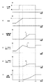
ここで、図5を用いて、第2実施形態に係る水−アルコール相排出処理を具体的に説明する。図5(a)は相分離の有無を示すグラフであり、図5(b)はエンジン4の負荷を示すグラフであり、図5(c)は低濃度側インジェクタ24からの燃料噴射量(ここでは水−アルコール相の燃料の排出量を意味する)を示すグラフである。また、図5(d)はモータMG1の検出トルクを示しており、図5(e)はモータMG2の発生トルクを示しており、図5(f)は低濃度側インジェクタ24からの積算噴射量を示している。なお、図5(a)〜(f)の横軸には、時間を示している。
Here, the water-alcohol phase discharge process according to the second embodiment will be specifically described with reference to FIG. FIG. 5A is a graph showing the presence or absence of phase separation, FIG. 5B is a graph showing the load of the engine 4, and FIG. 5C is a fuel injection amount from the low concentration side injector 24 (here) Is a graph showing a water-alcohol phase fuel discharge amount. 5D shows the detected torque of the motor MG1, FIG. 5E shows the generated torque of the motor MG2, and FIG. 5F shows the integrated injection amount from the low
図5(a)に示すように、時刻t10において、相分離検出装置25が相分離を検出する。そして、図5(b)に示すように、時刻t11において、エンジン4の負荷が閾値X1を超える。そのため、ECU10bは、図5(c)に示すように、低濃度側タンク21内の燃料(水−アルコール相内の燃料)の噴射を開始する。この場合、ECU10bは、モータMG1の出力に基づいてエンジン4のトルク(出力)を算出し、水−アルコール相における燃料の噴射の前後におけるトルク変化が所定値を越えない範囲で、図5(c)中の矢印Y1に示すように、低濃度側タンク21から噴射させる燃料量を徐々に増加させる。これにより、水−アルコール相内における燃料を速やかに排出することができる。
As shown in FIG. 5A, at time t10, the phase
このように低濃度側タンク21内の燃料を噴射することにより、図5(d)中の矢印Y2で示すように、モータMG1の出力に基づいて検出される、エンジン4のトルクが減少する。詳しくは、水−アルコール相内の燃料噴射量を増加しているため、これに伴ってエンジン4のトルクが減少している。そのため、ECU10bは、水−アルコール相における燃料の噴射の前後におけるエンジン4のトルク変化分が補われるように、モータMG2よりトルクを発生させるための制御を行う。具体的には、図5(e)中の矢印Y3に示すように、ECU10bは、エンジン4のトルクの減少に応じてモータMG2から発生させるトルクを増加させる。そして、図5(f)に示すように、時刻t13において、積算噴射量が必要燃料消費量X2に到達する。そのため、ECU10bは、水−アルコール相内における燃料の排出を終了する。
By injecting the fuel in the low-
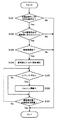
図6は、第2実施形態に係る水−アルコール相排出処理を示すフローチャートである。この処理は、ECU10bが所定の周期で繰り返し実行する。
FIG. 6 is a flowchart showing a water-alcohol phase discharge process according to the second embodiment. This process is repeatedly executed by the
ステップS201〜S204の処理は、第1実施形態に係る水−アルコール相排出処理におけるステップS101〜S104の処理と同様であるため(図3参照)、その説明を省略する。以下では、ステップS205以降の処理を説明する。 Since the process of step S201-S204 is the same as the process of step S101-S104 in the water-alcohol phase discharge process which concerns on 1st Embodiment (refer FIG. 3), the description is abbreviate | omitted. In the following, the processing after step S205 will be described.
ステップS205では、ECU10bは、エンジン4を定常状態に移行させるための制御を行う。この場合、ECU10bは、モータMG2を制御することによって、要求トルクに対する過不足分をモータMG2の発生トルクによって補う。このように定常状態において低濃度側タンク21内の燃料を噴射することにより、当該噴射の前後におけるトルク変化を、モータMG1の出力から精度良く算出することが可能となる。ステップS205の処理が終了すると、処理はステップS206に進む。
In step S205, the
ステップS206では、ECU10bは、低濃度側タンク21内における燃料の噴射前と噴射後とにおけるトルク変化が、閾値未満であるか否かを判定する。ここでは、ECU10bは、低濃度側タンク21内における燃料の噴射量を増加しても良いか否かを判定している。この場合、ECU10bは、モータMG1の出力に基づいてトルク変化を算出する。なお、ステップS206で用いる閾値は、バッテリ32の充電状態(SOC(State Of Charge))に基づいて設定することが好ましい。バッテリ32の充電状態に応じて、モータMG2が出力可能なトルクが決まるからである。即ち、バッテリ32の充電状態に応じて、低濃度側タンク21内の燃料の噴射前後におけるトルク変化を補うことが可能なMG2の発生トルクが決まるからである。
In step S206, the
トルク変化が閾値未満である場合(ステップS206;Yes)、処理はステップS207に進む。この場合には、低濃度側タンク21内の燃料噴射量を増加しても問題がないので、ステップS207では、ECU10bは燃料噴射量を増加する。これにより、水−アルコール相内における燃料を速やかに排出させることができる。そして、処理はステップS208に進む。一方、トルク変化が閾値以上である場合には(ステップS206;No)、低濃度側タンク21内の燃料噴射量を増加するべきではないので、燃料噴射量を増加することなく、処理はステップS208に進む。
If the torque change is less than the threshold value (step S206; Yes), the process proceeds to step S207. In this case, since there is no problem even if the fuel injection amount in the low
ステップS208では、ECU10bは、モータMG2を制御することによってトルクを発生させる、即ちモータアシストを実行する。具体的には、ECU10bは、低濃度側タンク21内の燃料噴射に起因するエンジン4のトルク変化分が補われるように、モータMG2からトルクを発生させる。そして、処理はステップS209に進む。
In step S208, the
ステップS209では、ECU10bは、低濃度側タンク21からの積算噴射量が必要燃料消費量を超えたか否かを判定する。即ち、水−アルコール相の排出を終了しても良いか否かを判定する。積算噴射量が必要燃料消費量を超えた場合(ステップS209;Yes)、処理は当該フローを抜ける。即ち、ECU10bは、水−アルコール相の燃料の排出を終了する。一方、積算噴射量が必要燃料消費量を超えていない場合(ステップS209;No)、処理はステップS209に戻る。この場合には、積算噴射量が必要燃料消費量を超えるまで、水−アルコール相の燃料の排出を継続する。
In step S209, the
このように第2実施形態に係る水−アルコール相排出処理によれば、低濃度側タンク21内の水−アルコール相の排出に起因するトルク変化を抑制しつつ、水−アルコール相を適切に外部に排出することができる。また、第2実施形態によれば、低濃度側タンク21内の水−アルコール相を速やかに排出することができる。
As described above, according to the water-alcohol phase discharge process according to the second embodiment, the water-alcohol phase is appropriately removed from the outside while suppressing the torque change caused by the discharge of the water-alcohol phase in the low
なお、第2実施形態においては、水−アルコール相における燃料の排出を実行する場合、エンジン回転数と負荷との関係を示す動作線を、通常運転時よりも低回転高負荷側に変更することが好ましい。具体的には、図7に示すように、水−アルコール相の排出時に用いる動作線71を、通常運転時に用いる動作線70よりも低回転高負荷側に設定する。なお、図7は、横軸にエンジン回転数を示し、縦軸にエンジン4の負荷を示している。このように動作線を設定することにより、水−アルコール相における燃料を噴射した場合において、噴射量全体に占める水及びアルコールの割合を更に小さくすることができるため、エンジン4の出力に与える影響を効果的に抑制することが可能となる。
In the second embodiment, when the fuel is discharged in the water-alcohol phase, the operation line indicating the relationship between the engine speed and the load is changed to a low rotation and high load side than during normal operation. Is preferred. Specifically, as shown in FIG. 7, the
[第3実施形態]
次に、本発明の第3実施形態について説明する。第3実施形態においても、第1実施形態及び第2実施形態と同様に、相分離が生じている場合に水−アルコール相排出処理を実行する。しかしながら、第3実施形態では、水−アルコール相の燃料を吸気通路3中に排出する代わりに、エンジン4の排気通路5中に排出する点で、第1実施形態及び第2実施形態と異なる。
[Third Embodiment]
Next, a third embodiment of the present invention will be described. In the third embodiment, similarly to the first embodiment and the second embodiment, the water-alcohol phase discharge process is executed when phase separation occurs. However, the third embodiment differs from the first and second embodiments in that water-alcohol phase fuel is discharged into the exhaust passage 5 of the engine 4 instead of being discharged into the
(全体構成)
図8は、第3実施形態に係る内燃機関の制御装置が適用された車両の概略構成図を示す。なお、図8では、実線矢印がガスや燃料の流れを示し、破線矢印が信号の入出力を示している。以下では、第1実施形態と同一の構成要素に対しては同一の符号を付し、その説明を省略する。
(overall structure)
FIG. 8 is a schematic configuration diagram of a vehicle to which the control device for an internal combustion engine according to the third embodiment is applied. In FIG. 8, solid arrows indicate the flow of gas and fuel, and broken arrows indicate input / output of signals. Below, the same code | symbol is attached | subjected to the component same as 1st Embodiment, and the description is abbreviate | omitted.
第3実施形態に係る車両は、排気側燃料供給通路23bと、三方弁41と、排気側インジェクタ42と、触媒43と、O2センサ(酸素濃度センサ)44と、を備える点で、第1実施形態に係る車両と構成が異なる。また、ECU10aの代わりにECU10cを有している。 The vehicle according to the third embodiment is the first in that it includes an exhaust side fuel supply passage 23b, a three-way valve 41, an exhaust side injector 42, a catalyst 43, and an O 2 sensor (oxygen concentration sensor) 44. The configuration differs from the vehicle according to the embodiment. Moreover, it has ECU10c instead of ECU10a.
排気側燃料供給通路23bは、三方弁41を介して燃料供給通路23と接続されている。この場合、三方弁41を切り替えることによって、燃料供給通路23に対して排気側燃料供給通路23bを接続することができる。また、排気側燃料供給通路23bは、排気通路5上に設けられた排気側インジェクタ42に接続されている。そのため、三方弁41を切り替えて、燃料供給通路23と排気側燃料供給通路23bとを接続すると、排気側インジェクタ42から排気通路5中に燃料が噴射される。即ち、低濃度側タンク21内の燃料が排気通路5中に噴射される。
The exhaust side fuel supply passage 23 b is connected to the
また、排気側インジェクタ42は、排気ガスを浄化可能な触媒43の上流側の排気通路5上に設けられている。このような位置に排気側インジェクタ42を設けているのは、排気側インジェクタ42から噴射した燃料を触媒43で浄化するためである。更に、触媒43の下流側の排気通路5上には、酸素濃度を検出するO2センサ44が設けられている。 The exhaust-side injector 42 is provided on the exhaust passage 5 on the upstream side of the catalyst 43 that can purify the exhaust gas. The exhaust side injector 42 is provided at such a position in order to purify the fuel injected from the exhaust side injector 42 by the catalyst 43. Further, an O 2 sensor 44 for detecting the oxygen concentration is provided on the exhaust passage 5 on the downstream side of the catalyst 43.
ECU10cは、CPU、ROM、RAM、A/D変換器及び入出力インターフェースなどを含んで構成される。ECU10cは、第1実施形態に係るECU10aなどと同様に、相分離検出装置25が相分離が生じていると判定した場合に、低濃度側タンク21内の水−アルコール相の燃料を排出させる制御を実行する。しかしながら、ECU10cは、ポンプ22、三方弁41、及び排気側インジェクタ42を制御することによって、低濃度側タンク21内の水−アルコール相の燃料を排気通路5中に排出する点で、ECU10aとは異なる。
The ECU 10c includes a CPU, a ROM, a RAM, an A / D converter, an input / output interface, and the like. Similar to the
(水−アルコール相排出処理)
次に、第3実施形態に係る水−アルコール相排出処理について説明する。第3実施形態においても、低濃度側タンク21内で相分離が生じている場合に、低濃度側タンク21内の水−アルコール相における燃料を排出するための処理を行う。詳しくは、第3実施形態では、水−アルコール相の燃料を排気通路5中に排出する。
(Water-alcohol phase discharge treatment)
Next, the water-alcohol phase discharge process according to the third embodiment will be described. Also in the third embodiment, when phase separation occurs in the low
更に、第3実施形態では、触媒43中の空燃比(A/F)がストイキとなるように空燃比の制御を実行する。このような制御を実行する理由は、以下の通りである。上記のような排気通路5中への燃料の噴射によって、排気通路5中の空燃比はリッチになる傾向にある。この場合、触媒43における空燃比がリッチになると、空燃比がストイキである場合と比較すると、触媒43の浄化率が低下する傾向にある。そのため、ECU10cは、水−アルコール相の燃料を排出している際に、スロットルバルブ3の開度を大きくしてエンジン4の出口における空燃比をリーンにすることによって、触媒43における空燃比をストイキに維持する。これにより、水−アルコール相における燃料の排出時において、触媒43における空燃比をストイキに維持することができるため、触媒43の浄化率を確保することが可能となる。
Furthermore, in the third embodiment, the air-fuel ratio is controlled so that the air-fuel ratio (A / F) in the catalyst 43 becomes stoichiometric. The reason for executing such control is as follows. Due to the fuel injection into the exhaust passage 5 as described above, the air-fuel ratio in the exhaust passage 5 tends to be rich. In this case, when the air-fuel ratio in the catalyst 43 becomes rich, the purification rate of the catalyst 43 tends to decrease as compared with the case where the air-fuel ratio is stoichiometric. Therefore, the ECU 10c increases the air-fuel ratio at the catalyst 43 by increasing the opening of the
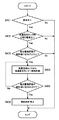
図9は、第3実施形態に係る水−アルコール相排出処理を示すフローチャートである。この処理は、ECU10cが所定の周期で繰り返し実行する。 FIG. 9 is a flowchart showing a water-alcohol phase discharge process according to the third embodiment. This process is repeatedly executed by the ECU 10c at a predetermined cycle.
ステップS301及びS302の処理は、第1実施形態に係る水−アルコール相排出処理におけるステップS101及びS102の処理と同様であるため(図3参照)、その説明を省略する。以下では、ステップS303以降の処理を説明する。 Since the process of step S301 and S302 is the same as the process of step S101 and S102 in the water-alcohol phase discharge process which concerns on 1st Embodiment (refer FIG. 3), the description is abbreviate | omitted. Below, the process after step S303 is demonstrated.
ステップS303では、ECU10cは、触媒43が暖機しているか否かを判定する。ここでは、ECU10cは、水−アルコール相の燃料を排気通路5中に排出した場合に、触媒43が当該燃料を浄化可能な状態にあるか否かを判定している。触媒暖機後である場合(ステップS303;Yes)、処理はステップS304に進み、触媒暖機後でない場合(ステップS303;No)、処理は当該フローを抜ける。 In step S303, the ECU 10c determines whether or not the catalyst 43 is warmed up. Here, when the water-alcohol phase fuel is discharged into the exhaust passage 5, the ECU 10c determines whether or not the catalyst 43 is in a state capable of purifying the fuel. If it is after the catalyst is warmed up (step S303; Yes), the process proceeds to step S304. If it is not after the catalyst is warmed up (step S303; No), the process exits the flow.
ステップS304では、ECU10cは、ポンプ22、三方弁41、及び排気側インジェクタ42を制御することによって、低濃度側タンク21内の燃料を噴射する。即ち、低濃度側タンク21内の水−アルコール相の燃料を排気通路5中に排出する。そして、処理はステップS305に進む。
In step S304, the ECU 10c injects the fuel in the low
ステップS305では、ECU10cは、触媒43の下流の排気通路5における空燃比がリッチにずれているか否かを判定する。ステップS305の判定は、触媒43における空燃比をストイキに戻すための制御を実行すべき状況にあるか否かを判定するために行う。この場合、ECU10cは、O2センサ44から供給される検出信号に基づいて判定を行う。空燃比がリッチにずれている場合(ステップS305;Yes)、処理はステップS306に進み、空燃比がリッチにずれていない場合(ステップS305;No)、処理はステップS307に進む。 In step S305, the ECU 10c determines whether or not the air-fuel ratio in the exhaust passage 5 downstream of the catalyst 43 is richly shifted. The determination in step S305 is performed to determine whether or not the control for returning the air-fuel ratio in the catalyst 43 to stoichiometric is to be executed. In this case, the ECU 10c makes a determination based on the detection signal supplied from the O 2 sensor 44. If the air-fuel ratio has shifted to rich (step S305; Yes), the process proceeds to step S306. If the air-fuel ratio has not shifted to rich (step S305; No), the process proceeds to step S307.
ステップS306では、ECU10cは、触媒43の空燃比をストイキにするために、スロットルバルブ3の開度(スロットル開度)を大きくする制御を行う。つまり、スロットル開度を大きくすることによって、エンジン4の出口における空燃比をリーンにする。これにより、触媒43の空燃比をストイキに維持することができるため、触媒43の浄化率を確保することができる。なお、ECU10cは、排気側インジェクタ42からの燃料噴射量などに基づいて、スロットル開度を決定する。ステップS306の処理が終了すると、処理はステップS307に進む。 In step S306, the ECU 10c performs control to increase the opening of the throttle valve 3 (throttle opening) in order to make the air-fuel ratio of the catalyst 43 stoichiometric. That is, the air-fuel ratio at the outlet of the engine 4 is made lean by increasing the throttle opening. Thereby, since the air-fuel ratio of the catalyst 43 can be maintained at stoichiometric, the purification rate of the catalyst 43 can be ensured. The ECU 10c determines the throttle opening based on the fuel injection amount from the exhaust-side injector 42 and the like. When the process of step S306 ends, the process proceeds to step S307.
ステップS307では、ECU10cは、低濃度側タンク21からの積算噴射量が必要燃料消費量を超えたか否かを判定する。即ち、水−アルコール相の排出を終了しても良いか否かを判定する。積算噴射量が必要燃料消費量を超えた場合(ステップS307;Yes)、処理は当該フローを抜ける。即ち、ECU10cは、水−アルコール相の排出を終了する。一方、積算噴射量が必要燃料消費量を超えていない場合(ステップS307;No)、処理はステップS305に戻る。この場合には、積算噴射量が必要燃料消費量を超えるまで、触媒43における空燃比をストイキに維持する処理を行いつつ、低濃度側タンク21内の燃料噴射を継続する。
In step S307, the ECU 10c determines whether or not the integrated injection amount from the low
このように第3実施形態に係る水−アルコール相排出処理によれば、触媒43の排気ガスに対する浄化率を確保しつつ、水−アルコール相の燃料を排気通路5中に適切に排出することができる。 Thus, according to the water-alcohol phase discharge process according to the third embodiment, the water-alcohol phase fuel can be appropriately discharged into the exhaust passage 5 while ensuring the purification rate of the catalyst 43 with respect to the exhaust gas. it can.
[第4実施形態]
次に、本発明の第4実施形態について説明する。第4実施形態においても、第1実施形態等と同様に、相分離が生じている場合に水−アルコール相排出処理を実行する。しかしながら、第4実施形態では、低濃度側タンク21の水−アルコール相の燃料をエンジン4又は排気通路5に対して排出する代わりに、この水−アルコール相の燃料を高濃度側タンク11に排出する点で、第1実施形態などと異なる。
[Fourth Embodiment]
Next, a fourth embodiment of the present invention will be described. Also in the fourth embodiment, the water-alcohol phase discharge process is executed when phase separation occurs as in the first embodiment. However, in the fourth embodiment, instead of discharging the water-alcohol phase fuel from the low
(全体構成)
図10は、第4実施形態に係る内燃機関の制御装置が適用された車両の概略構成図を示す。なお、図10では、実線矢印がガスや燃料の流れを示し、破線矢印が信号の入出力を示している。以下では、第1実施形態と同一の構成要素に対しては同一の符号を付し、その説明を省略する。
(overall structure)
FIG. 10 is a schematic configuration diagram of a vehicle to which the control device for an internal combustion engine according to the fourth embodiment is applied. In FIG. 10, solid line arrows indicate the flow of gas and fuel, and broken line arrows indicate signal input and output. Below, the same code | symbol is attached | subjected to the component same as 1st Embodiment, and the description is abbreviate | omitted.
第4実施形態に係る車両は、燃料供給通路50と、ポンプ51と、を備える点で、第1実施形態に係る車両と構成が異なる。また、ECU10aの代わりにECU10dを有している。燃料供給通路50は、一端(燃料吸い込み口50a)が低濃度側タンク21内に位置しており、他端が高濃度側タンク11内に位置している。燃料供給通路50の内部には、ポンプ51によって吸引された低濃度側タンク21内の燃料29が、矢印90で示すように流れる。
The vehicle according to the fourth embodiment is different from the vehicle according to the first embodiment in that it includes a
また、燃料供給通路50の燃料吸い込み口50aは、燃料供給通路23の燃料吸い込み口23aよりも下方(低濃度側タンク21の底面部側)に設けられている。これにより、相分離によって生じた水−アルコール相を燃料吸い込み口50aから吸引して、相分離境界面の位置を下降させることによって、相分離境界面を燃料吸い込み口23aよりも下方に位置させることができる。言い換えると、相分離境界面が燃料吸い込み口50aよりも下方に位置するが、燃料吸い込み口23aよりも上方に位置するといった状況は生じない。そのため、低濃度側タンク21内の燃料29を用いる始動時において、ガソリン相におけるガソリン濃度が高い燃料を確実に燃料吸い込み口23aから吸引させることができるため、始動性を向上させることが可能となる。
Further, the
ECU10dは、CPU、ROM、RAM、A/D変換器及び入出力インターフェースなどを含んで構成される。ECU10dは、第1実施形態に係るECU10aなどと同様に、相分離検出装置25が相分離が生じていると判定した場合に、低濃度側タンク21内の水−アルコール相の燃料を排出させる制御を実行する。しかしながら、ECU10dは、ポンプ51を制御することによって、低濃度側タンク21内の水−アルコール相の燃料を高濃度側タンク11に排出する点で、ECU10aとは異なる。
The
(水−アルコール相排出処理)
次に、第4実施形態に係る水−アルコール相排出処理について説明する。第4実施形態においても、低濃度側タンク21内で相分離が生じている場合に、低濃度側タンク21内の水−アルコール相における燃料を排出するための処理を行う。詳しくは、第4実施形態では、水−アルコール相の燃料を高濃度側タンク11に排出する。これによっても、前述したような相分離に起因する始動性の悪化などの不具合を適切に解消することができる。なお、高濃度側タンク11内の燃料19のアルコール濃度が十分に高いため、水−アルコール相の燃料を高濃度側タンク11に排出しても、高濃度側タンク11において相分離は発生しないと考えられる。
(Water-alcohol phase discharge treatment)
Next, the water-alcohol phase discharge process according to the fourth embodiment will be described. Also in the fourth embodiment, when phase separation occurs in the low
図11は、第4実施形態に係る水−アルコール相排出処理を示すフローチャートである。この処理は、ECU10dが所定の周期で繰り返し実行する。
FIG. 11 is a flowchart showing a water-alcohol phase discharge process according to the fourth embodiment. This process is repeatedly executed by the
ステップS401では、ECU10dは、車両が停車中であるか否かを判定する。車両が停車中である場合には、相分離の検出や相分離境界面の検出などの処理を精度良く行うことができるため、ステップS401の判定を行っている。車両が停車中である場合(ステップS401;Yes)、処理はステップS402に進み、車両が停車中でない場合(ステップS401;No)、処理は当該フローを抜ける。
In step S401, the
ステップS402では、ECU10dは、低濃度側タンク21内で相分離が生じているか否かを判定する。この場合、ECU10dは、相分離検出装置25から供給される検出信号に基づいて判定を行う。相分離が生じている場合(ステップS402;Yes)、処理はステップS403に進み、相分離が生じていない場合(ステップS402;No)、処理は当該フローを抜ける。
In step S402, the
ステップS403では、ECU10dは、相分離境界面が燃料吸い込み口23aよりも上方に位置するか否かを判定する。この場合、ECU10dは、相分離境界面検出装置26から供給される検出信号に基づいて判定を行う。相分離境界面が燃料吸い込み口23aよりも上方に位置する場合(ステップS403;Yes)、燃料吸い込み口23aから水−アルコール相内の燃料が吸引されてしまうため、相分離境界面の位置を下降させるべく、処理はステップS404に進む。一方、相分離境界面が燃料吸い込み口23aよりも下方に位置している場合(ステップS403;No)、燃料吸い込み口23aからガソリン相内の燃料を吸引することができるため(水−アルコール相内の燃料が吸引される可能性がかなり低いため)、処理は当該フローを抜ける。この場合には、相分離境界面の位置を下降させる必要はない。
In step S403, the
ステップS404では、ECU10dは、ポンプ51を制御することによって、低濃度側タンク21内の燃料を高濃度側タンク11へ供給する。即ち、低濃度側タンク21内の水−アルコール相における燃料を燃料吸い込み口50aから吸引することによって、排出を行う。そして、処理はステップS405に進む。
In step S <b> 404, the
ステップS405では、ECU10dは、相分離境界面が燃料吸い込み口23aよりも下方に位置するか否かを判定する。この場合も、ECU10dは、相分離境界面検出装置26から供給される検出信号に基づいて判定を行う。
In step S405, the
相分離境界面が燃料吸い込み口23aよりも下方に位置する場合(ステップS405;Yes)、燃料吸い込み口23aからガソリン相内の燃料を吸引することができるため、処理はステップS406に進む。この場合、ステップS406において、ECU10dは、高濃度側タンク11への燃料の供給を停止する。即ち、ECU10dは、低濃度側タンク21の水−アルコール相における燃料の排出を終了する。そして、処理は当該フローを抜ける。一方、相分離境界面が燃料吸い込み口23aよりも上方に位置している場合(ステップS405;No)、燃料吸い込み口23aから水−アルコール相内の燃料が吸引されてしまうため、相分離境界面の位置を下降させるべく、ステップS404の処理を再度実行する。即ち、ECU10dは、水−アルコール相の排出を継続する。
When the phase separation boundary surface is located below the
このように第4実施形態に係る水−アルコール相排出処理によっても、低濃度側タンク21内の水−アルコール相の燃料を適切に外部に排出することができる。したがって、第3実施形態によれば、低濃度側タンク21の燃料29を用いて適切な始動を行うことが可能となる。
Thus, the water-alcohol phase discharge process according to the fourth embodiment can appropriately discharge the water-alcohol phase fuel in the low
[第5実施形態]
次に、本発明の第5実施形態について説明する。第5実施形態においても、第1実施形態等と同様に、相分離が生じている場合に水−アルコール相排出処理を実行する。しかしながら、第5実施形態では、冷間始動時に相分離が生じている場合に、低濃度側タンク21を攪拌した後にエンジン4の始動を開始し、始動の開始後に相分離が生じている場合に水−アルコール相の燃料を排出する制御を行う点で、第1実施形態などと異なる。
[Fifth Embodiment]
Next, a fifth embodiment of the present invention will be described. Also in the fifth embodiment, the water-alcohol phase discharge process is executed when phase separation occurs as in the first embodiment. However, in the fifth embodiment, when phase separation occurs during cold start, the engine 4 is started after stirring the low-
(全体構成)
図12は、第5実施形態に係る内燃機関の制御装置が適用された車両の概略構成図を示す。なお、図12では、実線矢印がガスや燃料の流れを示し、破線矢印が信号の入出力を示している。以下では、第1実施形態と同一の構成要素に対しては同一の符号を付し、その説明を省略する。
(overall structure)
FIG. 12 is a schematic configuration diagram of a vehicle to which the control device for an internal combustion engine according to the fifth embodiment is applied. In FIG. 12, solid arrows indicate the flow of gas and fuel, and broken arrows indicate input / output of signals. Below, the same code | symbol is attached | subjected to the component same as 1st Embodiment, and the description is abbreviate | omitted.
第5実施形態に係る車両は、攪拌装置65を有し、ECU10aの代わりにECU10eを有する点で、第1実施形態に係る車両と構成が異なる。攪拌装置65は、低濃度側タンク21に設けられ、例えば、図示しないポンプや燃料循環通路などを備えて構成される。燃料循環通路は、ポンプの動作によって、低濃度側タンク21内の燃料29が流通する。燃料循環通路の一端は低濃度側タンク21の底面部付近に設けられ、燃料循環通路の他端は低濃度側タンク21の天井部付近に設けられる。上記したポンプの動作によって燃料29が燃料循環通路内を循環することによって、低濃度側タンク21内の燃料29が攪拌される。なお、攪拌装置65は、上記したものに限定はされない。
The vehicle according to the fifth embodiment is different from the vehicle according to the first embodiment in that it includes an
ECU10eは、CPU、ROM、RAM、A/D変換器及び入出力インターフェースなどを含んで構成される。ECU10eは、第1実施形態に係るECUなどと同様に、低濃度側タンク21内の水−アルコール相の燃料を排出させる制御を実行する。詳しくは、ECU10eは、冷間始動時に相分離が生じている場合に、攪拌装置65を制御することによって低濃度側タンク21を攪拌した後にエンジン4の始動を開始し、始動の開始後に相分離が生じている場合に水−アルコール相の燃料を排出する制御を行う。
The
(水−アルコール相排出処理)
次に、第5実施形態に係る水−アルコール相排出処理について説明する。第5実施形態では、冷間始動時に相分離が生じている場合に、低濃度側タンク21を攪拌した後にエンジン4の始動を開始し、このような始動の開始後に相分離が生じている場合に水−アルコール相における燃料を排出するための処理を行う。
(Water-alcohol phase discharge treatment)
Next, the water-alcohol phase discharge process according to the fifth embodiment will be described. In the fifth embodiment, when phase separation occurs during cold start, the engine 4 is started after stirring the low-
図13は、第5実施形態に係る水−アルコール相排出処理を示すフローチャートである。この処理は、ECU10eが所定の周期で繰り返し実行する。
FIG. 13 is a flowchart showing a water-alcohol phase discharge process according to the fifth embodiment. This process is repeatedly executed by the
まず、ステップS501では、ECU10eは、冷間時に始動要求があったか否かを判定する。冷間時に始動要求があった場合(ステップS501;Yes)、処理はステップS502に進み、冷間時に始動要求がなかった場合(ステップS501;No)、処理は当該フローを抜ける。ステップS502では、ECU10eは、相分離検出装置25から供給される検出信号に基づいて、低濃度側タンク21内で相分離が生じているか否かを判定する。相分離が生じている場合(ステップS502;Yes)、処理はステップS503に進み、相分離が生じていない場合(ステップS502;No)、処理は当該フローを抜ける。
First, in step S501, the
ステップS503では、ECU10eは、攪拌装置65を制御することによって、低濃度側タンク21を攪拌する。このように攪拌することによって、相分離が一時的に解消されるため、燃料吸い込み口23aから、水−アルコール相内の燃料のみが吸引されることを抑制できる。そして、処理はステップS504に進み、ECU10eは、エンジン4を始動する。次に、処理はステップS505に進む。
In step S503, the
ステップS505では、ECU10eは、相分離が発生しているか否かを再度判定する。相分離が生じている場合(ステップS505;Yes)、処理はステップS503に進む。一方、相分離が生じていない場合(ステップS505;No)、処理はステップS505に戻る。この場合、相分離が検出するまでステップS505の判定を繰り返す。こうするのは、上記したように攪拌しても燃料29に含まれる水分の割合が大きく変わるわけではないので、ある程度の時間が経過すると相分離が再度生じるからである。
In step S505, the
ステップS506では、ECU10eは、ポンプ22及び低濃度側インジェクタ24を制御することによって、低濃度側タンク21内の燃料を噴射する。即ち、低濃度側タンク21内の水−アルコール相における燃料を排出する。そして、処理はステップS507に進む。
In step S506, the
ステップS507では、ECU10eは、低濃度側タンク21からの積算噴射量が必要燃料消費量を超えたか否かを判定する。この必要燃料消費量は、前述した手法で算出される。積算噴射量が必要燃料消費量を超えた場合(ステップS507;Yes)、処理は当該フローを抜ける。この場合には、水−アルコール相の燃料の排出を終了する。一方、積算噴射量が必要燃料消費量を超えていない場合(ステップS507;No)、処理はステップS507に戻る。この場合には、水−アルコール相の燃料の排出を継続する。
In step S507, the
このように第5実施形態に係る水−アルコール相排出処理によれば、冷間始動時には低濃度側タンク21の攪拌を実行するので、冷間始動時においても適切な始動を行うことができると共に、エンジン始動後は、低濃度側タンク21内の水−アルコール相の燃料を外部に排出することが可能となる。
As described above, according to the water-alcohol phase discharge process according to the fifth embodiment, since the agitation of the low-
なお、上記では、低濃度側タンク21を攪拌した後に、低濃度側タンク21内の燃料をエンジン4に対して噴射する実施形態を示したが、これに限定はされない。他の例では、低濃度側タンク21を攪拌した後に、低濃度側タンク21内の燃料をエンジン4に対して噴射する代わりに、第3実施形態で示したように排気通路5中に噴射したり、或いは、第4実施形態で示したように高濃度側タンク11中に噴射したりするこができる。また、第5実施形態に係る内燃機関の制御装置をハイブリッド車両に適用した場合には、第2実施形態に示したように、水−アルコール相の燃料の噴射前と噴射後における出力変化分をモータMG2の出力によって補うことも可能である。
In the above description, the embodiment in which the fuel in the low
[第6実施形態]
次に、本発明の第6実施形態について説明する。第6実施形態においては、低濃度側タンク21におけるアルコール濃度を上昇させるために、相分離の発生している低濃度側タンク21に対して高濃度側タンク11内の燃料を供給する制御を行う点で、前述した第1実施形態などと異なる。こうするのは、低濃度側タンク21のアルコール濃度を上昇させることによって、低濃度側タンク21の相分離を解消することができるからである。
[Sixth Embodiment]
Next, a sixth embodiment of the present invention will be described. In the sixth embodiment, in order to increase the alcohol concentration in the low
図14は、第6実施形態に係る内燃機関の制御装置が適用された車両の概略構成図を示す。なお、図14では、実線矢印がガスや燃料の流れを示し、破線矢印が信号の入出力を示している。以下では、第1実施形態と同一の構成要素に対しては同一の符号を付し、その説明を省略する。 FIG. 14 is a schematic configuration diagram of a vehicle to which the control device for an internal combustion engine according to the sixth embodiment is applied. In FIG. 14, solid arrows indicate the flow of gas and fuel, and broken arrows indicate input / output of signals. Below, the same code | symbol is attached | subjected to the component same as 1st Embodiment, and the description is abbreviate | omitted.
第6実施形態に係る車両は、燃料供給通路60と、ポンプ61と、攪拌装置65と、を有する点で、第1実施形態に係る車両と構成が異なる。また、ECU10aの代わりにECU10fを有している。燃料供給通路60は、一端が低濃度側タンク21内に位置しており、他端が高濃度側タンク11内に位置している。燃料供給通路60の内部には、ポンプ61によって吸引された高濃度側タンク11内の燃料19が、矢印91で示すように流れる。そして、燃料供給通路60を流れた燃料19は、低濃度側タンク21に供給される。攪拌装置65は、前述した第5実施形態で示したものと同様であり、低濃度側タンク21内の燃料29を攪拌する。
The vehicle according to the sixth embodiment is different from the vehicle according to the first embodiment in that it includes a
ECU10fは、CPU、ROM、RAM、A/D変換器及び入出力インターフェースなどを含んで構成される。ECU10fは、相分離が生じている場合に、攪拌装置65を制御することによって攪拌を実行すると共に、ポンプ61を制御することによって高濃度側タンク11から低濃度側タンク21へ燃料を供給する。
The ECU 10f includes a CPU, a ROM, a RAM, an A / D converter, an input / output interface, and the like. When phase separation has occurred, the ECU 10 f performs stirring by controlling the stirring
ここで、高濃度側タンク11から低濃度側タンク21へ燃料を供給する理由を、図15を用いて説明する。
Here, the reason why fuel is supplied from the high
図15は、アルコール濃度(横軸)と相分離を起こす水分割合(縦軸)との関係を示すグラフである。これより、アルコール濃度が濃くなるほど相分離が生じる水分割合が多くなることがわかる。即ち、アルコール濃度が濃くなるほど、相分離するのに必要な水分割合が上昇するため、相分離が生じにくくなるといえる。以上より、第6実施形態では、低濃度側タンク21内のアルコール濃度を上昇させることによって低濃度側タンク21で生じている相分離を解消させるために、アルコール濃度が高い燃料が貯蔵された高濃度側タンク11から低濃度側タンク21へ燃料を供給する。
FIG. 15 is a graph showing the relationship between the alcohol concentration (horizontal axis) and the water ratio causing the phase separation (vertical axis). From this, it can be seen that the higher the alcohol concentration, the greater the proportion of water that causes phase separation. That is, it can be said that the higher the alcohol concentration is, the higher the water ratio necessary for phase separation is, so that phase separation is less likely to occur. As described above, in the sixth embodiment, in order to eliminate the phase separation occurring in the low
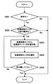
次に、第6実施形態に係る処理について説明する。図16は、第6実施形態に係る処理を示すフローチャートである。この処理は、ECU10fが所定の周期で繰り返し実行する。 Next, processing according to the sixth embodiment will be described. FIG. 16 is a flowchart showing processing according to the sixth embodiment. This process is repeatedly executed by the ECU 10f at a predetermined cycle.
ステップS601では、ECU10dは、車両が停車中であるか否かを判定する。車両が停車中である場合(ステップS601;Yes)、処理はステップS602に進み、車両が停車中でない場合(ステップS601;No)、処理は当該フローを抜ける。ステップS602では、ECU10dは、相分離検出装置25から供給される検出信号に基づいて、低濃度側タンク21内で相分離が生じているか否かを判定する。相分離が生じている場合(ステップS602;Yes)、処理はステップS603に進み、相分離が生じていない場合(ステップS602;No)、処理は当該フローを抜ける。
In step S601, the
ステップS603では、ECU10fは、ポンプ61を制御することによって、高濃度側タンク11から低濃度側タンク21へ所定量の燃料を供給する。こうするのは、低濃度側タンク21内の燃料のアルコール濃度を上昇させることによって、低濃度側タンク21で発生する相分離を解消するためである。なお、低濃度側タンク21へ供給する燃料の所定量は、低濃度側タンク21内の燃料のアルコール濃度の上昇が極力抑えられるような量に設定することが好ましい。低濃度側タンク21内の燃料のアルコール濃度が上昇し過ぎてしまうと、始動性が悪化してしまう可能性があるからである。以上のステップS603の処理が終了すると、処理はステップS604に進む。
In step S <b> 603, the ECU 10 f supplies a predetermined amount of fuel from the high
ステップS604では、ECU10fは、攪拌装置65を制御することによって、低濃度側タンク21内を攪拌する。このような攪拌を実行することによって、低濃度側タンク21において、供給された燃料や相分離している水及びアルコールなどを効果的に溶解させることができるため、相分離を速やかに解消することが可能となる。ステップS604の処理が終了すると、処理はステップS605に進む。
In step S604, the ECU 10f agitates the inside of the low
ステップS605では、ECU10fは、相分離検出装置25から供給される検出信号に基づいて、相分離が解消したか否かを判定する。相分離が解消している場合(ステップS605;Yes)、処理は当該フローを抜ける。一方、相分離が解消していない場合(ステップS605;No)、処理はステップS603に戻る。この場合、低濃側タンク21への燃料供給と、低濃側タンク21内の燃料の攪拌を再度実行する。
In step S605, the ECU 10f determines whether or not the phase separation has been canceled based on the detection signal supplied from the phase
このように第6実施形態によれば、低濃度側タンク21のアルコール濃度を上昇させる制御を行うことによって、低濃度側タンク21で発生する相分離を適切に解消することができる。したがって、第6実施形態によれば、低濃度側タンク21の燃料29を用いて適切な始動を行うことが可能となる。
As described above, according to the sixth embodiment, the control of increasing the alcohol concentration in the low-
なお、上記では、低濃度側タンク21に対して高濃度側タンク11内の燃料を供給する制御のみを行う実施形態を示したが、これに限定はされない。他の例では、エンジン1の始動前に低濃度側タンク21に対して高濃度側タンク11内の燃料を供給する制御を行うと共に、エンジン1の始動後に、前述した第1実施形態乃至第4実施形態のいずれかの方法によって、相分離した水−アルコール相の燃料を低濃度側タンク21の外部に排出する制御を行うことができる。これにより、効果的に、低濃度側タンク21で発生している相分離を解消することが可能となる。
In the above description, the embodiment has been described in which only the control for supplying the fuel in the high
[第7実施形態]
次に、本発明の第7実施形態について説明する。第7実施形態においては、低濃度側タンク21内の燃料の温度を上昇させる制御を行う点で、前述した第1実施形態などと異なる。こうするのは、低濃度側タンク21の燃料の温度を上昇させることによって、低濃度側タンク21の相分離を解消することができるからである。
[Seventh Embodiment]
Next, a seventh embodiment of the present invention will be described. The seventh embodiment is different from the first embodiment described above in that control for increasing the temperature of the fuel in the low
図17は、第7実施形態に係る内燃機関の制御装置が適用された車両の概略構成図を示す。第7実施形態に係る内燃機関の制御装置は、前述した第2実施形態と同様に、ハイブリッド車両に適用される。そのため、以下では、第2実施形態と同一の構成要素に対しては同一の符号を付し、その説明を省略する。なお、図17では、実線矢印がガスや燃料の流れを示し、破線矢印が信号の入出力を示している。 FIG. 17 is a schematic configuration diagram of a vehicle to which the control device for an internal combustion engine according to the seventh embodiment is applied. The control apparatus for an internal combustion engine according to the seventh embodiment is applied to a hybrid vehicle as in the second embodiment described above. Therefore, below, the same code | symbol is attached | subjected with respect to the component same as 2nd Embodiment, and the description is abbreviate | omitted. In FIG. 17, solid arrows indicate the flow of gas and fuel, and broken arrows indicate input / output of signals.
第7実施形態に係る車両は、伝熱部材71、72、73を有し、ECU10bの代わりにECU10gを有する点で、前述した第2実施形態に係る車両と構成が異なる。伝熱部材71は、モータMG1と低濃度側タンク21とを接続し、伝熱部材72は、モータMG2と低濃度側タンク21とを接続し、伝熱部材73は、インバータ73と低濃度側タンク21とを接続する。伝熱部材71、72、73は、熱伝導率の高い金属などによって構成され、それぞれモータMG1、モータMG2、及びインバータ73(以下、これらを単に「モータ類」とも呼ぶ。)で発生した熱を低濃度側タンク21に伝達可能に構成されている。
The vehicle according to the seventh embodiment is different from the vehicle according to the second embodiment described above in that it includes
ECU10gは、CPU、ROM、RAM、A/D変換器及び入出力インターフェースなどを含んで構成される。ECU10gは、低外気温において相分離が生じている場合に、エンジン4によって始動する前に、モータMG2を制御することによって、モータMG2の発生トルクを用いた走行(以下、「EV走行」と呼ぶ。)を実行する。つまり、ECU10gは、このようなEV走行を実行することによって、モータ類を発熱させる。このような発熱が伝熱部材71、72、73を介して低濃度側タンク21に伝達されることにより、低濃度側タンク21を加熱することができる。即ち、低濃度側タンク21内の燃料の温度を上昇させることができる。
The
ここで、低濃度側タンク21内の燃料の温度を上昇させる理由を、図18を用いて説明する。
Here, the reason why the temperature of the fuel in the low
図18は、燃料の温度(横軸)と相分離を起こす水分割合(縦軸)との関係を示すグラフである。これより、燃料の温度が高くなるほど相分離が生じる水分割合が多くなることがわかる。即ち、燃料の温度が高くなるほど、相分離するのに必要な水分割合が上昇するため、相分離が生じにくくなるといえる。以上より、第7実施形態では、低濃度側タンク21で生じている相分離を解消させるために、低濃度側タンク21内の燃料の温度を上昇させる。
FIG. 18 is a graph showing the relationship between the fuel temperature (horizontal axis) and the water ratio (vertical axis) causing phase separation. From this, it can be seen that the higher the temperature of the fuel, the greater the proportion of moisture that causes phase separation. That is, it can be said that the higher the temperature of the fuel, the higher the proportion of water necessary for phase separation, so that phase separation is less likely to occur. As described above, in the seventh embodiment, the temperature of the fuel in the low
次に、第7実施形態に係る処理について説明する。図19は、第7実施形態に係る処理を示すフローチャートである。この処理は、ECU10gが所定の周期で繰り返し実行する。
Next, processing according to the seventh embodiment will be described. FIG. 19 is a flowchart showing processing according to the seventh embodiment. This process is repeatedly executed by the
まず、ステップS701では、ECU10gは、車両の駐車時に低濃度側タンク21で相分離が発生したか否かを、相分離検出装置25から供給される検出信号に基づいて判定する。相分離が生じている場合(ステップS701;Yes)、処理はステップS702に進み、相分離が生じていない場合(ステップS701;No)、処理は当該フローを抜ける。
First, in step S701, the
ステップS702では、ECU10gは、低外気温において運転要求があったか否かを判定する。ここでは、エンジン4による始動が可能な状態であるか否かを判定している。運転要求があった場合(ステップS702;Yes)、処理はステップS703に進む。この場合には、エンジン4による始動が困難であるといえる。一方、運転要求がなかった場合(ステップS702;No)、処理は当該フローを抜ける。
In step S702, the
ステップS703では、ECU10gは、モータMG2を制御することによってEV走行を実行する。このようなEV走行を実行することによって、モータ類は発熱する。そして、モータ類で発生した熱は、伝熱部材71、72、73を介して低濃度側タンク21に伝達される。これにより、低濃度側タンク21が加熱されることとなる。上記のようなステップS703の処理を実行するのは、低濃度側タンク21内の燃料の温度を上昇させることによって、低濃度側タンク21で生じている相分離を解消させるためである。そして、処理はステップS704に進む。
In step S703, the
ステップS704では、ECU10gは、相分離検出装置25から供給される検出信号に基づいて、相分離が解消したか否かを判定する。相分離が解消している場合(ステップS704;Yes)、処理はステップS705に進む。この場合には、相分離が発生していないため、低濃度側タンク21内の燃料を用いて始動しても問題はないため、ECU10gは、エンジン4を始動させる(ステップS705)。そして、処理は当該フローを抜ける。一方、相分離が解消していない場合(ステップS704;No)、処理はステップS703に戻る。この場合、相分離が解消するまで、EV走行を継続する。
In step S704, the
このように第7実施形態によれば、低濃度側タンク21の温度を上昇させる制御を行うことによって、低濃度側タンク21で発生する相分離を適切に解消することができる。したがって、第7実施形態によれば、低濃度側タンク21の燃料29を用いて適切な始動を行うことが可能となる。
As described above, according to the seventh embodiment, it is possible to appropriately eliminate the phase separation generated in the low
なお、上記では、伝熱部材71、72、73を用いて、モータ類の発熱を低濃度側タンク21に対して伝達する実施形態を示したが、これに限定はされない。他の例では、伝熱部材71、72、73を用いる代わりに、低濃度側タンク21に対してモータ類を接触させるように車両内の構成要素を配置することによって、モータ類の熱を直接的に低濃度側タンク21に対して伝達することができる。更に他の例では、伝熱部材71、72、73を用いる代わりに、インバータ31を冷却する水を用いて、インバータ31の発熱を低濃度側タンク21に対して伝達することができる。
In the above description, the
また、上記では、低濃度側タンク21の温度を上昇させるための制御のみを行う実施形態を示したが、これに限定はされない。他の例では、エンジン1の始動前に、低濃度側タンク21の温度を上昇させるための制御を行うと共に、エンジン1の始動後に、前述した第1実施形態乃至第4実施形態のいずれかの方法によって、相分離した水−アルコール相の燃料を低濃度側タンク21の外部に排出する制御を行うことができる。このような制御を実行することにより、効果的に、低濃度側タンク21で発生している相分離を解消することが可能となる。
In the above description, the embodiment is shown in which only the control for increasing the temperature of the low
更に、他の例では、エンジン1の始動前に、低濃度側タンク21の温度を上昇させるための制御を行うと共に、低濃度側タンク21の燃料を攪拌する制御を行うことも可能である。
Furthermore, in another example, before starting the
3 スロットルバルブ
4 エンジン
5 排気通路
10a、10b、10c、10d、10e、10f、10g ECU
11 高濃度側タンク
12、22 ポンプ
14 高濃度側インジェクタ
21 低濃度側タンク
24 低濃度側インジェクタ
25 相分離検出装置
26 相分離境界面検出装置
MG1、MG2 モータ
3 Throttle valve 4 Engine 5
11 High
Claims (10)
前記第1の燃料タンク内で、前記混合燃料が、前記ガソリンの相と、前記アルコール及び水によって構成される相とに相分離しているか否かを判定する相分離判定手段と、
前記相分離判定手段が前記相分離が生じていると判定した場合、前記相分離している前記アルコール及び水によって構成される相内の燃料を、強制的に前記第1の燃料タンクの外部に排出するための制御を行う排出制御手段と、を備えていることを特徴とする内燃機関の制御装置。 A first fuel tank for storing a mixed fuel of gasoline and alcohol, and a second fuel tank for storing a mixed fuel of gasoline and alcohol having a higher alcohol concentration than the first fuel tank; A control device for an internal combustion engine that controls an internal combustion engine having
Phase separation determination means for determining whether or not the mixed fuel is phase-separated into a phase of the gasoline and a phase composed of the alcohol and water in the first fuel tank;
When the phase separation determination means determines that the phase separation has occurred, the fuel in the phase constituted by the alcohol and water that are phase-separated is forcibly placed outside the first fuel tank. An internal combustion engine control apparatus comprising: a discharge control means for performing control for discharging.
前記排出制御手段による前記燃料の排出時における前記内燃機関の出力と、車両の要求出力との差分が、モータによる出力によって補われるように前記モータに対して制御を行うモータ制御手段を備えることを特徴とする請求項1に記載の内燃機関の制御装置。 The emission control means discharges the fuel so as to be used for combustion in the internal combustion engine,
Motor control means for controlling the motor so that the difference between the output of the internal combustion engine and the required output of the vehicle when the fuel is discharged by the discharge control means is supplemented by the output from the motor. The control apparatus for an internal combustion engine according to claim 1, wherein the control apparatus is an internal combustion engine.
前記攪拌手段によって攪拌した後に、前記第1の燃料タンク内の燃料を用いて前記内燃機関を始動させる始動手段と、を備え、
前記排出制御手段は、前記始動手段による始動後に前記相分離が生じている場合に、前記燃料を排出することを特徴とする請求項1乃至4のいずれか一項に記載の内燃機関の制御装置。 Agitation means for agitating the fuel in the first fuel tank when the phase separation occurs during a cold start of the internal combustion engine;
Starting means for starting the internal combustion engine using the fuel in the first fuel tank after stirring by the stirring means,
The control device for an internal combustion engine according to any one of claims 1 to 4, wherein the discharge control means discharges the fuel when the phase separation occurs after the start by the start means. .
前記排出制御手段は、前記排出終了判定手段が前記排出を終了するべきと判定した場合に、当該排出を終了することを特徴とする請求項1乃至7のいずれか一項に記載の内燃機関の制御装置。 A discharge end determination means for determining whether or not to end the discharge of the fuel by the discharge control means;
The internal combustion engine according to any one of claims 1 to 7, wherein the discharge control means ends the discharge when the discharge end determination means determines that the discharge should be ended. Control device.
Priority Applications (1)
| Application Number | Priority Date | Filing Date | Title |
|---|---|---|---|
| JP2006113038A JP2007285193A (en) | 2006-04-17 | 2006-04-17 | Control device of internal combustion engine |
Applications Claiming Priority (1)
| Application Number | Priority Date | Filing Date | Title |
|---|---|---|---|
| JP2006113038A JP2007285193A (en) | 2006-04-17 | 2006-04-17 | Control device of internal combustion engine |
Publications (1)
| Publication Number | Publication Date |
|---|---|
| JP2007285193A true JP2007285193A (en) | 2007-11-01 |
Family
ID=38757211
Family Applications (1)
| Application Number | Title | Priority Date | Filing Date |
|---|---|---|---|
| JP2006113038A Withdrawn JP2007285193A (en) | 2006-04-17 | 2006-04-17 | Control device of internal combustion engine |
Country Status (1)
| Country | Link |
|---|---|
| JP (1) | JP2007285193A (en) |
Cited By (1)
| Publication number | Priority date | Publication date | Assignee | Title |
|---|---|---|---|---|
| JP2011153601A (en) * | 2010-01-28 | 2011-08-11 | Toyota Motor Corp | Exhaust gas cleaning method and device thereof |
-
2006
- 2006-04-17 JP JP2006113038A patent/JP2007285193A/en not_active Withdrawn
Cited By (1)
| Publication number | Priority date | Publication date | Assignee | Title |
|---|---|---|---|---|
| JP2011153601A (en) * | 2010-01-28 | 2011-08-11 | Toyota Motor Corp | Exhaust gas cleaning method and device thereof |
Similar Documents
| Publication | Publication Date | Title |
|---|---|---|
| JP4911206B2 (en) | Vehicle control apparatus and control method | |
| US9925975B2 (en) | Method and system for hybrid vehicle control | |
| EP2806127A1 (en) | Control device for internal combustion engine | |
| JP6992656B2 (en) | Hybrid vehicle control device | |
| JP2007231838A (en) | Automatic stop device for internal combustion engine | |
| JP2011043089A (en) | Control apparatus of vehicle and control method | |
| JP2010113974A (en) | Battery temperature control device for vehicle | |
| JP5527264B2 (en) | Control device for hybrid vehicle | |
| JP2007285193A (en) | Control device of internal combustion engine | |
| JP2006220038A (en) | Intake control device for internal combustion engine | |
| JP2007283854A (en) | Starting device for engine | |
| JP4582048B2 (en) | Control device for internal combustion engine | |
| JP2007326464A (en) | Control device of hybrid vehicle | |
| JP2009024638A (en) | Vibration control device | |
| JP2007137321A (en) | Internal combustion engine controller for hybrid vehicle | |
| JP2013133040A (en) | Hybrid vehicle and control method for the same | |
| JP2007315292A (en) | Internal combustion engine control device | |
| JP2010144573A (en) | Fuel injection control device for internal combustion engine | |
| JP5434774B2 (en) | Fuel supply device for internal combustion engine | |
| JP2020189550A (en) | Control device of hybrid vehicle | |
| JP2010138746A (en) | Control system for internal combustion engine | |
| JP4821805B2 (en) | INTERNAL COMBUSTION ENGINE DEVICE, VEHICLE HAVING THE SAME, AND METHOD FOR CONTROLLING INTERNAL COMBUSTION ENGINE DEVICE | |
| JP2011247166A (en) | Engine control device | |
| JP2006063899A (en) | Control device for internal combustion engine, automobile equipped with the same and method for estimating temperature of fuel injection valve of internal combustion engine | |
| JP2017133486A (en) | Control device of internal combustion engine |
Legal Events
| Date | Code | Title | Description |
|---|---|---|---|
| A621 | Written request for application examination |
Free format text: JAPANESE INTERMEDIATE CODE: A621 Effective date: 20080521 |
|
| A761 | Written withdrawal of application |
Free format text: JAPANESE INTERMEDIATE CODE: A761 Effective date: 20090114 |