JP2007283371A - Spool bush of die casting machine - Google Patents

Spool bush of die casting machine Download PDF

Info

Publication number
JP2007283371A
JP2007283371A JP2006114657A JP2006114657A JP2007283371A JP 2007283371 A JP2007283371 A JP 2007283371A JP 2006114657 A JP2006114657 A JP 2006114657A JP 2006114657 A JP2006114657 A JP 2006114657A JP 2007283371 A JP2007283371 A JP 2007283371A
Authority
JP
Japan
Prior art keywords
spool bush
plunger tip
spool
bush
peripheral surface
Prior art date
Legal status (The legal status is an assumption and is not a legal conclusion. Google has not performed a legal analysis and makes no representation as to the accuracy of the status listed.)
Pending
Application number
JP2006114657A
Other languages
Japanese (ja)
Inventor
Shiyouzo Tejima
将蔵 手島
Yoshiro Kashiwabara
芳郎 栢原
Current Assignee (The listed assignees may be inaccurate. Google has not performed a legal analysis and makes no representation or warranty as to the accuracy of the list.)
Toyota Motor Corp
Original Assignee
Toyota Motor Corp
Priority date (The priority date is an assumption and is not a legal conclusion. Google has not performed a legal analysis and makes no representation as to the accuracy of the date listed.)
Filing date
Publication date
Application filed by Toyota Motor Corp filed Critical Toyota Motor Corp
Priority to JP2006114657A priority Critical patent/JP2007283371A/en
Publication of JP2007283371A publication Critical patent/JP2007283371A/en
Pending legal-status Critical Current

Links

Images

Abstract

<P>PROBLEM TO BE SOLVED: To provide an improved spool bush for die casting machine with which in the case of opening the dies, a product biscuit is pushed out by smoothly advancing a plunger tip in the spool bush. <P>SOLUTION: Since this spool bush 1 arranges non-contacting part 12 which does not contact with the outer peripheral surface of a plunger tip 7 at the rear side from the front end surface 7a of the plunger tip 7 in the case of filling up and solidifying the molten metal, and on the inner peripheral surface from a prescribed position 18 at the front side of the rear end surface 7b of the plunger tip 7 to the front end part 1a of the spool bush 1 in the case of opening the dies; when the dies are opened, the peripheral edge part of the front end part 7a of the plunger tip 7 is not encroached upon the inner peripheral surface of the spool bush 1, and this sliding resistance can be made to small, and the plunger tip 7 can smoothly be advanced in the spool bush 1 and the product biscuit can be pushed out. <P>COPYRIGHT: (C)2008,JPO&INPIT

Description

本発明は、内部をプランジャーチップが摺動する、ダイカスト鋳造機のスプールブッシュに関するもので、詳しくは、型開き時、プランジャーチップの溶湯を押圧する前端面の周縁部がスプールブッシュの内周面に食い込むことがなく、円滑に前進して製品ビスケットを押し出せるように改良されたスプールブッシュに関するものである。   The present invention relates to a spool bush of a die casting machine in which a plunger tip slides, and more specifically, a peripheral portion of a front end surface that presses a molten metal of a plunger tip when the mold is opened is an inner periphery of the spool bush. The present invention relates to a spool bush improved so as to smoothly advance and extrude a product biscuit without biting into the surface.

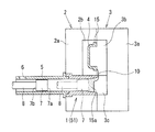
一般に、ダイカスト鋳造機において、図1に示すように、固定金型2には、溶湯をキャビティ4内へ供給する円筒状のスプールブッシュ51(図6参照)が嵌挿されている。このスプールブッシュ51の後端には、円筒状のプランジャースリーブ5が接続されており、このプランジャースリーブ5の後部の周壁部には、溶湯を供給するための注湯口6が設けられている。また、円柱状のプランジャーチップ7がプランジャースリーブ5内からスプールブッシュ51内に亘って摺動可能に設けられている。   In general, in a die-casting machine, as shown in FIG. 1, a cylindrical spool bush 51 (see FIG. 6) for supplying molten metal into the cavity 4 is fitted into the fixed mold 2. A cylindrical plunger sleeve 5 is connected to the rear end of the spool bush 51, and a pouring port 6 for supplying molten metal is provided on the peripheral wall portion of the rear portion of the plunger sleeve 5. . A cylindrical plunger tip 7 is slidably provided from the plunger sleeve 5 to the spool bush 51.

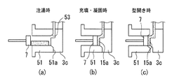
そして、図1及び図6(a)に示すように、固定金型2と可動金型3との型締め後に、プランジャースリーブ5の注湯口6から溶湯(図6(a)の斑点部分)が注湯される。続いて、プランジャーチップ7が、図6(a)の位置から前進して、その前端面7aによって、溶湯をプランジャースリーブ5からスプールブッシュ51に導き、流路10を経由して固定金型2の固定入れ子2bと、可動金型3の可動入れ子3bとの間に形成されたキャビティ4内に充填させる。充填後、プランジャーチップ7は、溶湯がキャビティ4内で凝固するまでの間さらに低速で前進し、キャビティ4内の溶湯に圧力を付与して、図6(b)に示す位置で停止される。
その後、図1及び図6(c)に示すように、キャビティ4内の溶湯が凝固して、可動金型3が固定金型2から離脱して型開きされると、鋳造成形品15(図1のキャビティ4内の斜線部)は可動金型3の可動入れ子3bに張り付いた状態で固定金型2から離脱すると共に、プランジャーチップ7も図6(b)の位置から前進して、製品ビスケット15a(図6(c)においてプランジャーチップ7とスプールコア3cとの間で溶湯が凝固されたもの)を、スプールブッシュ51内から押し出すように離脱させる。
なお、従来のスプールブッシュ51には、図6に示すように、その内周面とその前端部51aとの間にテーパ部53が設けられており、充填時、溶湯をキャビティ4内へ流動し易くすると共に、型開き時、スプールブッシュ51からの製品ビスケット15aの離脱を容易にしている。
Then, as shown in FIGS. 1 and 6 (a), after the fixed mold 2 and the movable mold 3 are clamped, the molten metal (spotted portion in FIG. 6 (a)) is introduced from the pouring port 6 of the plunger sleeve 5. Is poured. Subsequently, the plunger tip 7 advances from the position shown in FIG. 6A, and the molten metal is guided from the plunger sleeve 5 to the spool bush 51 by the front end surface 7a. The cavity 4 formed between the two fixed inserts 2b and the movable insert 3b of the movable mold 3 is filled. After filling, the plunger tip 7 advances further at a low speed until the molten metal solidifies in the cavity 4, applies pressure to the molten metal in the cavity 4, and stops at the position shown in FIG. 6 (b). .
Thereafter, as shown in FIGS. 1 and 6C, when the molten metal in the cavity 4 is solidified and the movable mold 3 is detached from the fixed mold 2 and opened, the cast molded product 15 (FIG. 1 in the cavity 4) is detached from the fixed mold 2 while sticking to the movable insert 3b of the movable mold 3, and the plunger tip 7 is also advanced from the position of FIG. The product biscuits 15 a (the molten metal solidified between the plunger tip 7 and the spool core 3 c in FIG. 6C) is released so as to be pushed out from the spool bush 51.
As shown in FIG. 6, the conventional spool bush 51 is provided with a tapered portion 53 between its inner peripheral surface and its front end portion 51a, and the molten metal flows into the cavity 4 during filling. In addition, the product biscuit 15a can be easily detached from the spool bush 51 when the mold is opened.

しかしながら、上述した鋳造工程において、図7(a)に示すように、スプールブッシュ51の前端部51aの下方にバリ等の異物52が付着した状態で、型締めが行われると、図7(b)に示すように、スプールコア3cが異物52に衝突することにより、スプールブッシュ51のスプールコア3c側の周壁部の下部が上方に押し上げられ、スプールブッシュ51のスプールコア3c側の部分が、図8の実線で示すような横長の楕円筒状に変形した状態となる。   However, in the above-described casting process, as shown in FIG. 7A, when mold clamping is performed in a state in which a foreign object 52 such as a burr is attached below the front end portion 51a of the spool bush 51, FIG. ), When the spool core 3c collides with the foreign object 52, the lower portion of the peripheral wall portion on the spool core 3c side of the spool bush 51 is pushed upward, and the portion on the spool core 3c side of the spool bush 51 is shown in FIG. 8 is in a state of being deformed into a horizontally long elliptical cylinder as indicated by a solid line.

このように、スプールブッシュ51のスプールコア3c側の部分が楕円筒状に変形した状態で、型開き時、プランジャーチップ7が、図6(b)の位置から図6(c)の位置まで製品ビスケット15aを押し出しながら前進すると、プランジャーチップ7の前端面7aの周縁部がスプールブッシュ51の内周面に食い込むようにして摺動するため、その摺動抵抗が大きくなってしまう。
そのために、プランジャーチップ7の前端面7aが円滑に製品ビスケット15aを押し出すことができず、プランジャーチップ7が製品ビスケット15aの移動に追従不能となり、キャビティ4内の鋳造成形品15(図1参照)と製品ビスケット15aとの間で切断されることがあり、この時期にスプールブッシュ51を交換するようにしている。
In this way, when the mold is opened with the portion on the spool core 3c side of the spool bush 51 deformed into an elliptical cylinder shape, the plunger tip 7 moves from the position shown in FIG. 6B to the position shown in FIG. 6C. When the product biscuits 15a are pushed forward and moved forward, the peripheral edge portion of the front end surface 7a of the plunger tip 7 slides so as to bite into the inner peripheral surface of the spool bush 51, so that the sliding resistance increases.
Therefore, the front end surface 7a of the plunger tip 7 cannot smoothly push out the product biscuit 15a, and the plunger tip 7 becomes unable to follow the movement of the product biscuit 15a, so that the cast molded product 15 in the cavity 4 (FIG. 1). And the product biscuit 15a, and the spool bush 51 is replaced at this time.

また、ダイカスト鋳造機のスプールブッシュの従来技術として、特許文献1には、スプールブッシュを、そのブッシュ本体の内周面にインサートライナーを嵌合させて構成し、ブッシュ本体とインサートライナーとの嵌合面であるインサートランナーの外周面に冷却用流体を流す冷却溝を設けており、スプールブッシュは、冷却水による冷却効果が十分で、金属溶湯が通過する際の温度上昇に伴う熱応力による割れが生じ難いことが開示されている。
特開2003−10953号公報
Further, as a prior art of a spool bush of a die casting machine, Patent Document 1 discloses that a spool bush is formed by fitting an insert liner to an inner peripheral surface of the bush body, and the bush body and the insert liner are fitted. Cooling grooves that allow cooling fluid to flow are provided on the outer peripheral surface of the insert runner, which is the surface, and the spool bushing is sufficiently cooled by the cooling water, and cracks due to thermal stress accompanying the temperature rise when the molten metal passes through It is disclosed that it is difficult to occur.
JP 2003-10953 A

しかしながら、特許文献1の発明は、スプールブッシュに冷却溝を設け、金属溶湯が通過する際の温度上昇に伴う熱応力による割れを生じ難くしたもので、上述した問題点、すなわち、型開き時に、プランジャーチップがスプールブッシュ内を製品ビスケットを押し出しながら前進する際、プランジャーチップの前端面の周縁部がスプールブッシュの内周面に食い込むようにして摺動するため、その摺動抵抗が大きくなってしまい、プランジャーチップが円滑に前進して製品ビスケットを押し出すことができない、という問題点を解決できるものではない。   However, the invention of Patent Document 1 is provided with a cooling groove in the spool bushing, which makes it difficult for cracks due to thermal stress accompanying the temperature rise when the molten metal passes through. When the plunger tip moves forward while pushing out the product biscuits in the spool bush, the peripheral edge of the front end surface of the plunger tip slides into the inner peripheral surface of the spool bush, so the sliding resistance increases. As a result, the problem that the plunger tip cannot be pushed forward and the product biscuit cannot be pushed out cannot be solved.

本発明は、かかる点に鑑みてなされたものであり、型開き時、プランジャーチップがスプールブッシュ内を円滑に前進して製品ビスケットを押し出せるように改良されたダイカスト鋳造機のスプールブッシュを提供することを目的とする。   The present invention has been made in view of the above points, and provides a spool bush of a die casting casting machine that is improved so that a plunger tip can smoothly advance in the spool bush and push out a product biscuit when the mold is opened. The purpose is to do.

本発明は、上記課題を解決するための手段として、請求項1に記載したダイカスト鋳造機のスプールブッシュの発明は、ダイカスト鋳造機に備えられた、内部をプランジャーチップが摺動するスプールブッシュであって、該スプールブッシュは、キャビティ内への溶湯の充填及び凝固時における前記プランジャーチップの前端面よりも後側で、且つ、型開き時における前記プランジャーチップの後端面よりも前側の所定位置から前記スプールブッシュの前端部までの内周面に、前記プランジャーチップの前端部の外周面と接触しない非接触部を設けたことを特徴とするものである。
請求項2に記載したダイカスト鋳造機のスプールブッシュの発明は、請求項1に記載した発明において、前記非接触部は、前記スプールブッシュの内周面に、前記所定位置よりも前側の位置から前記スプールブッシュの前端部に向かって漸次拡開するテーパ部を形成すると共に、前記所定位置から前記スプールブッシュの前端部に向かって、前記プランジャーチップの外周面よりも大径の略同一径で延びる大径凹設部を形成して構成されたことを特徴とするものである。
請求項3に記載したダイカスト鋳造機のスプールブッシュの発明は、請求項1に記載した発明において、前記非接触部は、前記スプールブッシュの内周面に、前記所定位置から前記スプールブッシュの前端部に向かって漸次拡開するテーパ部を形成して構成されたことを特徴とするものである。
According to the present invention, as a means for solving the above-mentioned problems, the invention of the spool bush of the die-casting machine according to claim 1 is a spool bush provided in the die-casting machine, in which the plunger tip slides. The spool bush is a predetermined rear side of the front end surface of the plunger tip during filling and solidification of the molten metal into the cavity and a front side of the rear end surface of the plunger tip during mold opening. A non-contact portion that does not contact the outer peripheral surface of the front end portion of the plunger tip is provided on the inner peripheral surface from the position to the front end portion of the spool bush.
The invention of the spool bush of the die-casting machine described in claim 2 is the invention described in claim 1, wherein the non-contact portion is formed on the inner peripheral surface of the spool bush from the position in front of the predetermined position. A tapered portion that gradually expands toward the front end portion of the spool bush is formed, and extends from the predetermined position toward the front end portion of the spool bush with substantially the same diameter that is larger than the outer peripheral surface of the plunger tip. It is characterized by forming a large-diameter recessed portion.
The invention of the spool bush of the die-casting machine according to claim 3 is the invention according to claim 1, wherein the non-contact portion is formed on the inner peripheral surface of the spool bush from the predetermined position to the front end portion of the spool bush. It is characterized in that it is formed by forming a tapered portion that gradually expands toward.

従って、請求項1に記載したダイカスト鋳造機のスプールブッシュの発明では、型開き時、プランジャーチップがスプールブッシュ内で製品ビスケットを押し出しながら前進する際、仮に、スプールブッシュのスプールコア側の部分が横長の楕円筒状に変形している状態であっても、プランジャーチップの前端面の周縁部がスプールブッシュの内周面に食い込むことがなくその摺動抵抗が小さいので、プランジャーチップが円滑に前進して製品ビスケットを押し出すようになる。
請求項2及び3に記載したダイカスト鋳造機のスプールブッシュの発明では、型開き時、プランジャーチップの前端面の周縁部がスプールブッシュの内周面に食い込むことがなく、プランジャーチップが円滑に前進して製品ビスケットを押し出し、しかも、スプールブッシュの前端部側の内周面が、その前端部に向かって漸次拡開するテーパ状に形成されていることから、充填時、溶湯がキャビティ内へ流動し易くなると共に、型開き時、製品ビスケットがスプールブッシュ内から離脱し易くなる。
Therefore, in the invention of the spool bush of the die casting machine according to the first aspect, when the plunger tip moves forward while pushing out the product biscuit in the spool bush when the mold is opened, the part on the spool core side of the spool bush is temporarily Even in the state of being deformed into a horizontally long elliptical cylinder, the peripheral edge of the front end surface of the plunger tip does not bite into the inner peripheral surface of the spool bush, and its sliding resistance is small, so the plunger tip is smooth. Proceed to push out the product biscuits.
In the invention of the spool bush of the die casting machine according to claims 2 and 3, the periphery of the front end surface of the plunger tip does not bite into the inner peripheral surface of the spool bush when the mold is opened, and the plunger tip is smooth. The product biscuits are pushed forward to push the product biscuits, and the inner peripheral surface on the front end side of the spool bush is formed in a tapered shape that gradually expands toward the front end, so that the molten metal enters the cavity during filling. In addition to being easy to flow, the product biscuits are easily detached from the spool bush when the mold is opened.

本発明によれば、型開き時、プランジャーチップがスプールブッシュ内を円滑に前進して製品ビスケットを押し出せるように改良されたダイカスト鋳造機のスプールブッシュを提供することができる。   ADVANTAGE OF THE INVENTION According to this invention, the spool bush of the die-casting machine improved so that a plunger chip can advance smoothly in a spool bush and can extrude a product biscuit can be provided at the time of a mold opening.

以下、本発明を実施するための最良の形態を図1〜図5に基いて詳細に説明する。なお、従来例と同一部材は、同一符号を使用して説明する。
一般に、ダイカスト鋳造機の主要部の構成は、図1に示すように、固定金型2と、固定金型2に対して略水平方向に移動して、型締め及び型開きをする可動金型3とを備えている。固定金型2は、固定主型2aに固定入れ子2bが保持されて構成されている。一方、可動金型3も、可動主型3aに可動入れ子3bが保持されて構成されており、可動入れ子3bには、後述するプランジャーチップ7と対向する部位に、可動入れ子3bと同期して可動するスプールコア3cが連設されている。そして、型締め時には、固定入れ子2bと可動入れ子3bとの間にキャビティ4が形成される。
Hereinafter, the best mode for carrying out the present invention will be described in detail with reference to FIGS. In addition, the same member as a prior art example is demonstrated using the same code | symbol.
In general, as shown in FIG. 1, the main part of the die casting machine has a fixed mold 2 and a movable mold that moves in a substantially horizontal direction with respect to the fixed mold 2 to clamp and open the mold. 3 is provided. The fixed mold 2 is configured by holding a fixed insert 2b on a fixed main mold 2a. On the other hand, the movable mold 3 is also configured by holding a movable nest 3b on a movable main mold 3a. The movable nest 3b is synchronized with the movable nest 3b at a portion facing a plunger chip 7 described later. A movable spool core 3c is continuously provided. At the time of clamping, a cavity 4 is formed between the fixed insert 2b and the movable insert 3b.

また、固定金型2の固定主型2aには、溶湯をキャビティ4内へ供給するべく、キャビティ4と連通する円筒状のスプールブッシュ1が嵌挿されている。このスプールブッシュ1の後端部には、内径が同一の円筒状のプランジャースリーブ5が接続されている。このプランジャースリーブ5の後部の周壁部に、溶湯を注湯するための注湯口6が形成されている。
さらに、スプールブッシュ1内及びプランジャースリーブ5内には、円柱状のプランジャーチップ7が摺動可能に設けられている。また、このプランジャーチップ7の後端面7bには、プランジャーロッド8が接続されている。このプランジャーロッド8には、射出シリンダ(図示略)が接続されており、射出シリンダの駆動により、プランジャーチップ7が、スプールブッシュ1内及びプランジャースリーブ5内を往復摺動する。
A cylindrical spool bush 1 communicating with the cavity 4 is fitted into the fixed main mold 2 a of the fixed mold 2 so as to supply molten metal into the cavity 4. A cylindrical plunger sleeve 5 having the same inner diameter is connected to the rear end portion of the spool bush 1. A pouring port 6 for pouring the molten metal is formed in the peripheral wall portion at the rear of the plunger sleeve 5.
Further, a cylindrical plunger tip 7 is slidably provided in the spool bush 1 and the plunger sleeve 5. A plunger rod 8 is connected to the rear end surface 7 b of the plunger tip 7. An injection cylinder (not shown) is connected to the plunger rod 8, and the plunger tip 7 slides back and forth in the spool bush 1 and the plunger sleeve 5 by driving the injection cylinder.

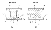
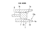
そして、本発明の実施の形態に係るダイカスト鋳造機のスプールブッシュ1は、図2に示すように、キャビティ4内への溶湯の充填及び凝固時(図2(a)の状態)におけるプランジャーチップ7の前端面7aよりも後側で、且つ、型開き時(図2(b)の状態)におけるプランジャーチップ7の後端面7bよりも前側の所定位置18からスプールブッシュ1の前端部1aまでの内周面に、プランジャーチップ7の前端部の外周面と接触しない非接触部12を設けて構成されている。   As shown in FIG. 2, the spool bush 1 of the die casting machine according to the embodiment of the present invention has a plunger tip at the time of filling and solidifying the molten metal into the cavity 4 (state shown in FIG. 2A). 7 to the front end portion 1a of the spool bush 1 from a predetermined position 18 on the rear side of the front end surface 7a and on the front side of the rear end surface 7b of the plunger tip 7 when the mold is opened (the state shown in FIG. 2B). The non-contact part 12 which does not contact the outer peripheral surface of the front end part of the plunger tip 7 is provided on the inner peripheral surface.

本スプールブッシュ1の非接触部12、12a、12bは、以下に説明する3形態のいずれかで構成される。
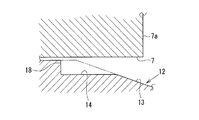
まず、第1の実施形態に係る非接触部12は、次のように構成されている。
すなわち、非接触部12は、図2及び図3に示すように、スプールブッシュ1の内周面に、非接触部12の起点となる所定位置18よりもやや前側の位置からスプールブッシュ1の前端部1aに向かって漸次拡開するテーパ部13を形成している。また、該テーパ部13の起点部分に、所定位置18からスプールブッシュ1の前端部1aに向かって、プランジャーチップ7の外径よりも大径の略同一径で延びる大径凹設部14を形成して構成されている。
The non-contact portions 12, 12a, 12b of the spool bush 1 are configured in any of three forms described below.
First, the non-contact part 12 which concerns on 1st Embodiment is comprised as follows.
That is, as shown in FIGS. 2 and 3, the non-contact portion 12 is formed on the inner peripheral surface of the spool bush 1 from the position slightly ahead of the predetermined position 18 that is the starting point of the non-contact portion 12. A tapered portion 13 that gradually expands toward the portion 1a is formed. Further, a large-diameter recessed portion 14 that extends from the predetermined position 18 toward the front end portion 1a of the spool bush 1 with a substantially same diameter larger than the outer diameter of the plunger tip 7 is formed at the starting portion of the tapered portion 13. Formed and configured.

次に、第2の実施形態に係る非接触部12aは、図4に示すように、スプールブッシュ1の内周面に、非接触部12aの起点となる所定位置18からスプールブッシュ1の前端部1aに向かって漸次拡開するテーパ部13を形成して構成されている。   Next, as shown in FIG. 4, the non-contact portion 12 a according to the second embodiment is disposed on the inner peripheral surface of the spool bush 1 from the predetermined position 18 that is the starting point of the non-contact portion 12 a. A tapered portion 13 is formed that gradually expands toward 1a.

次に、第3の実施形態に係る非接触部12bは、図5に示すように、スプールブッシュ1の内周面に、非接触部12bの起点となる所定位置18からスプールブッシュ1の前端部1aの手前までの範囲において、プランジャーチップ7の外径よりも大径の略同一径で延びる大径凹設部20を形成すると共に、その大径凹設部20とスプールブッシュ1の前端部1aとの間にテーパ部21を設けて構成されている。
なお、この第3の実施形態に係る非接触部12bにおいて、第1の実施形態に係る非接触部12との相違点は、大径凹設部20が形成される長さ及びテーパ部21の角度が相違点となる。
Next, as shown in FIG. 5, the non-contact portion 12 b according to the third embodiment is formed on the inner peripheral surface of the spool bush 1 from the predetermined position 18 that is the starting point of the non-contact portion 12 b. In the range up to 1a, a large-diameter recessed portion 20 extending substantially the same diameter as the outer diameter of the plunger tip 7 is formed, and the large-diameter recessed portion 20 and the front end of the spool bush 1 are formed. The taper part 21 is provided between 1a.
The non-contact portion 12b according to the third embodiment is different from the non-contact portion 12 according to the first embodiment in the length of the large-diameter recessed portion 20 and the taper portion 21. The angle is the difference.

そして、本スプールブッシュ1を採用したダイカスト鋳造機の作用を説明する。
まず、固定金型2側に可動金型3が移動して型締めが行われた後、プランジャースリーブ5の注湯口6から溶湯が注湯される。続いて、プランジャーチップ7が前進して、その前端面7aにより溶湯をプランジャースリーブ5からスプールブッシュ1に導き、キャビティ4内へ充填させる。充填後、プランジャーチップ7は、溶湯がキャビティ4内で凝固するまでの間さらに低速で前進し、キャビティ4内の溶湯に圧力を付与して、図2(a)に示す位置で停止される。
The operation of the die casting machine using the spool bush 1 will be described.
First, after the movable mold 3 is moved to the fixed mold 2 side and the mold is clamped, the molten metal is poured from the pouring port 6 of the plunger sleeve 5. Subsequently, the plunger tip 7 moves forward, and the molten metal is guided from the plunger sleeve 5 to the spool bush 1 by the front end surface 7 a and filled into the cavity 4. After filling, the plunger tip 7 advances further at a low speed until the molten metal solidifies in the cavity 4, applies pressure to the molten metal in the cavity 4, and stops at the position shown in FIG. .

その後、型開き時には、可動入れ子3b及びスプールコア3cが、固定入れ子2b及びスプールブッシュ1内から離脱するように移動すると同時に、プランジャーチップ7も図2(a)の位置から前進する。すると、鋳造成形品15が可動入れ子3bに張り付いた状態で固定入れ子2bから離脱すると共に、プランジャーチップ7が、スプールブッシュ1内に張り付いた製品ビスケット15aを押し出すようにして円滑に前進して、製品ビスケット15aをスプールブッシュ1内から離脱させて、図2(b)に示す位置で停止される。
この型開き時、プランジャーチップ7が、図2(a)の充填・凝固時の位置から図2(b)の型開き時の位置まで前進する際には、プランジャーチップ7の前端面7aの周縁部がスプールブッシュ1の内周面(非接触部12、12a、12b)に食い込むことがないので、その摺動抵抗が小さくなり、プランジャーチップ7がスプールブッシュ1内を円滑に前進でき製品ビスケット15aを押し出すことが可能となる。
Thereafter, at the time of mold opening, the movable nest 3b and the spool core 3c move so as to be detached from the fixed nest 2b and the spool bush 1, and at the same time, the plunger tip 7 advances from the position of FIG. Then, the cast molded product 15 is detached from the fixed insert 2b while sticking to the movable insert 3b, and the plunger tip 7 moves forward smoothly so as to push out the product biscuit 15a attached in the spool bush 1. Then, the product biscuit 15a is detached from the spool bush 1 and stopped at the position shown in FIG.
When the plunger tip 7 moves forward from the filling / solidification position shown in FIG. 2A to the position shown in FIG. 2B when the mold is opened, the front end surface 7a of the plunger tip 7 is opened. Since the peripheral edge portion does not bite into the inner peripheral surface (non-contact portion 12, 12a, 12b) of the spool bush 1, the sliding resistance is reduced, and the plunger tip 7 can smoothly advance in the spool bush 1. The product biscuit 15a can be extruded.

以上説明したように、本発明の実施の形態に係るダイカスト鋳造機のスプールブッシュ1には、その長さ方向の所定位置18からスプールブッシュ1の前端部1aまでの内周面に、プランジャーチップ7の前端部の外周面と接触しない非接触部12、12a、12bを設けているので、仮に、スプールブッシュ1のスプールコア3c側の部分が、横長の楕円筒状に変形していた場合でも、型開き時、プランジャーチップ7が、図2(a)の充填・凝固時の位置から図2(b)の型開き時の位置まで前進する際、プランジャーチップ7の前端面7aの周縁部がスプールブッシュ1の内周面(非接触部12、12a、12b)に食い込むことがなく、その摺動抵抗を小さくでき、プランジャーチップ7がスプールブッシュ1内を円滑に前進して製品ビスケット15aを押し出すことができる。
しかも、プランジャーチップ7が、図2(b)の型開き時の位置から後退する際にも、プランジャーチップ7の外周面がスプールブッシュ1のスプールコア3c側の内周面(非接触部12、12a、12b)に干渉することがないので、円滑に後退することができる。
As described above, the spool bush 1 of the die casting machine according to the embodiment of the present invention has a plunger tip on the inner peripheral surface from the predetermined position 18 in the length direction to the front end portion 1a of the spool bush 1. 7 is provided with non-contact portions 12, 12a, 12b that do not come into contact with the outer peripheral surface of the front end portion, even if the portion on the spool core 3c side of the spool bush 1 is deformed into a horizontally long elliptical cylinder. When the mold is opened, the peripheral edge of the front end surface 7a of the plunger chip 7 when the plunger chip 7 moves forward from the filling / solidification position of FIG. 2 (a) to the mold opening position of FIG. 2 (b). The part does not bite into the inner peripheral surface (non-contact part 12, 12a, 12b) of the spool bush 1 and its sliding resistance can be reduced, and the plunger tip 7 is smoothly advanced in the spool bush 1 and manufactured. It is possible to push out the biscuits 15a.
Moreover, even when the plunger tip 7 is retracted from the position when the mold is opened in FIG. 2B, the outer peripheral surface of the plunger tip 7 is the inner peripheral surface (non-contact portion) of the spool bush 1 on the spool core 3c side. 12, 12a, 12b), so that it can be moved backward smoothly.

図1は、本発明の実施の形態に係るスプールブッシュを採用したダイカスト鋳造機の主要部を示す図である。FIG. 1 is a diagram showing a main part of a die casting machine employing a spool bush according to an embodiment of the present invention. 図2は、本スプールブッシュの第1の実施形態に係る非接触部を示し、(a)は充填・凝固時、(b)は型開き時における、プランジャーチップのスプールブッシュ内での位置を示した図である。FIG. 2 shows a non-contact portion according to the first embodiment of the spool bush, wherein (a) shows the position of the plunger tip in the spool bush when filling and solidifying, and (b) when the mold is opened. FIG. 図3は、図2(a)のA部の拡大図である。FIG. 3 is an enlarged view of a portion A in FIG. 図4は、本スプールブッシュの第2の実施形態に係る非接触部を示した図である。FIG. 4 is a view showing a non-contact portion according to the second embodiment of the spool bush. 図5は、本スプールブッシュの第3の実施形態に係る非接触部を示した図である。FIG. 5 is a view showing a non-contact portion according to the third embodiment of the spool bush. 図6は、ダイカスト鋳造時のプランジャーチップの動きを段階的に示した図である。FIG. 6 is a diagram showing stepwise movement of the plunger tip during die casting. 図7は、スプールブッシュのスプールコア側が変形する際の過程を示した図である。FIG. 7 is a diagram showing a process when the spool core side of the spool bush is deformed. 図8は、スプールブッシュのスプールコア側の変形形状を示した図である。FIG. 8 is a view showing a deformed shape of the spool bush on the spool core side.

符号の説明Explanation of symbols

1 スプールブッシュ,1a 前端部,2 固定金型,3 可動金型,4 キャビティ,7 プランジャーチップ,7a 前端面,7b 後端面,12、12a、12b 非接触部,13 テーパ部,14 大径凹設部,15 鋳造成形品,15a 製品ビスケット,18 所定位置,20 大径凹設部,21 テーパ部
1 Spool bush, 1a Front end, 2 Fixed mold, 3 Movable mold, 4 Cavity, 7 Plunger tip, 7a Front end face, 7b Rear end face, 12, 12a, 12b Non-contact part, 13 Taper part, 14 Large diameter Recessed part, 15 Cast molding, 15a Product biscuit, 18 Predetermined position, 20 Large diameter recessed part, 21 Tapered part

Claims (3)

ダイカスト鋳造機に備えられた、内部をプランジャーチップが摺動するスプールブッシュであって、
該スプールブッシュは、キャビティ内への溶湯の充填及び凝固時における前記プランジャーチップの前端面よりも後側で、且つ、型開き時における前記プランジャーチップの後端面よりも前側の所定位置から前記スプールブッシュの前端部までの内周面に、前記プランジャーチップの前端部の外周面と接触しない非接触部を設けたことを特徴とするダイカスト鋳造機のスプールブッシュ。
A spool bush provided in a die casting machine, in which a plunger tip slides,
The spool bush is located at a position behind the front end surface of the plunger tip when filling and solidifying the molten metal into the cavity and from a predetermined position before the rear end surface of the plunger tip when opening the mold. A spool bush for a die-casting machine, wherein a non-contact portion that does not contact the outer peripheral surface of the front end portion of the plunger tip is provided on the inner peripheral surface up to the front end portion of the spool bush.
前記非接触部は、前記スプールブッシュの内周面に、前記所定位置よりも前側の位置から前記スプールブッシュの前端部に向かって漸次拡開するテーパ部を形成すると共に、前記所定位置から前記スプールブッシュの前端部に向かって、前記プランジャーチップの外周面よりも大径の略同一径で延びる大径凹設部を形成して構成されたことを特徴とする請求項1に記載のダイカスト鋳造機のスプールブッシュ。   The non-contact portion forms, on the inner peripheral surface of the spool bush, a tapered portion that gradually expands from a position in front of the predetermined position toward the front end of the spool bush, and from the predetermined position to the spool. 2. The die-casting according to claim 1, wherein a large-diameter recessed portion extending substantially in the same diameter as the outer peripheral surface of the plunger tip is formed toward the front end portion of the bush. The spool bush of the machine. 前記非接触部は、前記スプールブッシュの内周面に、前記所定位置から前記スプールブッシュの前端部に向かって漸次拡開するテーパ部を形成して構成されたことを特徴とする請求項1に記載のダイカスト鋳造機のスプールブッシュ。
The non-contact portion is configured by forming a tapered portion that gradually expands from the predetermined position toward the front end portion of the spool bush on the inner peripheral surface of the spool bush. Spool bushing of the described die casting machine.
JP2006114657A 2006-04-18 2006-04-18 Spool bush of die casting machine Pending JP2007283371A (en)

Priority Applications (1)

Application Number Priority Date Filing Date Title
JP2006114657A JP2007283371A (en) 2006-04-18 2006-04-18 Spool bush of die casting machine

Applications Claiming Priority (1)

Application Number Priority Date Filing Date Title
JP2006114657A JP2007283371A (en) 2006-04-18 2006-04-18 Spool bush of die casting machine

Publications (1)

Publication Number Publication Date
JP2007283371A true JP2007283371A (en) 2007-11-01

Family

ID=38755611

Family Applications (1)

Application Number Title Priority Date Filing Date
JP2006114657A Pending JP2007283371A (en) 2006-04-18 2006-04-18 Spool bush of die casting machine

Country Status (1)

Country Link
JP (1) JP2007283371A (en)

Cited By (1)

* Cited by examiner, † Cited by third party
Publication number Priority date Publication date Assignee Title
JP2012040599A (en) * 2010-08-23 2012-03-01 Toyota Motor Corp Casting apparatus

Cited By (1)

* Cited by examiner, † Cited by third party
Publication number Priority date Publication date Assignee Title
JP2012040599A (en) * 2010-08-23 2012-03-01 Toyota Motor Corp Casting apparatus

Similar Documents

Publication Publication Date Title
JP2007260687A (en) Method and apparatus for forming cylinder block in a half-melted state
CN105817603A (en) Shrinkage-prevention die casting die
JP2011224650A (en) Die casting device and die casting method
JP5587615B2 (en) Casting method
KR101619722B1 (en) Die-casting mold for aluminum cluth housing
JP2007283371A (en) Spool bush of die casting machine
JP5608103B2 (en) Horizontal injection die casting apparatus and die casting method
JP3619200B2 (en) Die casting method and die casting apparatus
JP2008068303A (en) Molding apparatus, extrusion pin, and molding method
JP6058458B2 (en) Die casting mold
JP2022134173A (en) Die casting device and die casting method
JP2000117411A (en) Die casting apparatus and die casting method
JP2006239721A (en) Chill vent insert
JP2009056503A (en) Molding metal mold and molding method
JP2003048047A (en) Casting method for thin die-casting product and its casting apparatus
JP2013128961A (en) Die for die casting and die casting method
JP2003220459A (en) Die-casting equipment
JP2005334909A (en) Die casting method
JP2008279498A (en) Mold and injection molding method
JP4450236B2 (en) Die casting method and die casting apparatus
JP2009214162A (en) Core for internal chill, and internal chill casting method
JP5440752B2 (en) Die casting mold
JP3766276B2 (en) Die casting mold
JP2010030117A (en) Mold for injection molding
JP4750141B2 (en) Die casting method