JP2007282964A - Game machine - Google Patents
Game machine Download PDFInfo
- Publication number
- JP2007282964A JP2007282964A JP2006115398A JP2006115398A JP2007282964A JP 2007282964 A JP2007282964 A JP 2007282964A JP 2006115398 A JP2006115398 A JP 2006115398A JP 2006115398 A JP2006115398 A JP 2006115398A JP 2007282964 A JP2007282964 A JP 2007282964A
- Authority
- JP
- Japan
- Prior art keywords
- coin
- notification
- command
- abnormal discharge
- coins
- Prior art date
- Legal status (The legal status is an assumption and is not a legal conclusion. Google has not performed a legal analysis and makes no representation as to the accuracy of the status listed.)
- Granted
Links
Images

Landscapes
- Slot Machines And Peripheral Devices (AREA)
Abstract
Description
本発明は、スロットマシン等に代表される遊技機に関する。 The present invention relates to a gaming machine represented by a slot machine or the like.
スロットマシン等の遊技機では、遊技機の各構成部を制御する制御装置により遊技管理が行われており、多数のコインを取得することができる大当たり状態に対する興味が遊技指向を高めている。その反面、短時間で大当たり状態が多数回に亘って連続すると、極めて大きな利益を得ることができるので、各種の不正行為が行われるおそれがあり、現実にそのような状況が生じている。 In a gaming machine such as a slot machine, game management is performed by a control device that controls each component of the gaming machine, and interest in a jackpot state in which a large number of coins can be acquired increases the game orientation. On the other hand, if the big hit state continues for a number of times in a short time, a very large profit can be obtained. Therefore, various fraudulent acts may be performed, and such a situation actually occurs.
この種の不正行為の1つに、投入されたコインがコイン通路を通過する過程で光センサから所定の検出信号を出力する投入コイン認識部(セレクタ)に対する不正行為がある。投入コイン認識部に対する不正行為は、セレクタゴトと称されており、コイン通路の光センサに対して行われる。 One of these types of fraud is a fraudulent act on the inserted coin recognition unit (selector) that outputs a predetermined detection signal from the optical sensor in the process in which the inserted coin passes through the coin passage. The fraudulent act on the inserted coin recognition unit is called a selector goto and is performed on the optical sensor in the coin path.
例えば、長尺物をコイン投入口から挿入し、光センサの投光部と受光部との間の光路を遮光することによって光センサからの出力状態を変化させ、その後に長尺物を引き抜くことによって光センサの光路を確保して出力状態を変化させることにより、1枚のコインが投入されたかのごとく制御装置に認識させている。そして、長尺物の往復操作を繰り返し行うことによって、所定枚数のコインが投入されたかのごとく制御装置に認識させている。しかも、かかる行為は、制御装置でコインとして認識可能な最大数まで行われるのが一般的である。 For example, inserting a long object from a coin slot, changing the output state from the optical sensor by blocking the optical path between the light projecting part and the light receiving part of the optical sensor, and then pulling out the long object By ensuring the optical path of the optical sensor and changing the output state, the control device recognizes as if one coin has been inserted. Then, by repeating the reciprocating operation of the long object, the control device recognizes it as if a predetermined number of coins have been inserted. In addition, such actions are generally performed up to the maximum number that can be recognized as coins by the control device.
セレクタからの検出信号に基づいて制御装置がコインとして認識すると、遊技機のいわゆるクレジット機能によって認識したコインを蓄積し、その枚数を電子的に記憶している。そして、クレジット精算ボタンが操作されるとクレジット機能が解除され、記憶した枚数のコインが実際に排出される。このように投入コインを不正に認識させる行為によりコインを排出させる場合、多数のコインを効率よく入手しようとすることから、遊技は殆ど行われないのが一般的である。 When the control device recognizes the coin as a coin based on the detection signal from the selector, the coin recognized by the so-called credit function of the gaming machine is accumulated and the number of the coins is stored electronically. When the credit settlement button is operated, the credit function is canceled and the stored number of coins are actually discharged. When coins are discharged by the act of illegally recognizing inserted coins in this way, since a large number of coins are to be obtained efficiently, games are generally hardly performed.
セレクタに対する不正行為に基づきコインが投入されたかのごとく認識させ、実際にコインが排出される状況が続くと、遊技場の経営者に対して多大な損害を与えるばかりでなく、購入したコインを用いて遊技を行っている遊技者には、遊技そのものに対する信頼性を減退させることが懸念される。従って、従来から適正に投入されたコインだけを認識することができるセレクタを備えた遊技機が提案されている(例えば、特許文献1参照)。 Recognizing as if coins were inserted based on fraudulent acts against the selector, and if the situation where coins are actually discharged continues, it will not only cause a great deal of damage to the management of the game hall, but also using purchased coins There is a concern for a player who is playing a game to reduce the reliability of the game itself. Therefore, a gaming machine having a selector that can recognize only properly inserted coins has been proposed (for example, see Patent Document 1).
特許文献1に記載されたセレクタを有する遊技機の場合、通過する1枚のコインMを同時に検出しうる程度に近接した状態で2個の近接センサが並設されているので、例えば長尺物をコイン投入口から挿入して行われるセレクタゴトは、長尺物を引き抜く過程で近接センサによる出力状態の変化の順序がコインの通過のときと反対になるのでセレクタゴトを検出可能である。
In the case of a gaming machine having a selector described in
しかしながら、光センサによって検知可能な赤外線等の光を発する発光体を先端側に有する器具がコイン投入口から挿入されることにより行われるセレクタゴトの場合、発光体の発光手法によっては近接センサの出力状態の変化がコインの通過のときと同じになり、遊技機の制御装置上でコインが投入されたかのごとく認識される。 However, in the case of a selector got that is made by inserting a light emitting body that emits light such as infrared rays that can be detected by an optical sensor from the coin slot, depending on the light emitting method of the light emitting body, the output state of the proximity sensor Is the same as when coins pass, and is recognized as if coins were inserted on the control device of the gaming machine.
このようにセレクタの光センサから出力された検出信号に基づいてセレクタゴトを検出するようにしているものの、コインを実際に排出するときにセレクタゴトが行われたことの検出は行われていない。従って、一旦セレクタゴトが行われると、特許文献1の遊技機であってもその後に検出は行われないので、認識した枚数のコインが排出されてしまう。なお、クレジット精算ボタンの操作によってコインが排出される場合、排出の際にスピーカから出力される報知音が、排出される最初の1枚目から大音量で出力されるように設定されている遊技機が知られている。しかし、このような遊技機であっても、コインを排出する際にセレクタゴトによって認識させた枚数のコインを排出するのか、購入したコインを用いて遊技を行って獲得したコインを払い出すのかを区別できないことから、セレクタゴトの防止には至っていない。
Thus, although the selector goat is detected based on the detection signal output from the optical sensor of the selector, it is not detected that the selector goat has been performed when the coin is actually ejected. Therefore, once the selector is made, even the gaming machine of
従って、上記課題に鑑みてなされた本発明の目的は、セレクタに対する不正行為に基づきコインが排出される際に、不正行為が行われた可能性が高い旨を報知することによってセレクタに対する不正行為を抑制することができる遊技機を提供することにある。 Therefore, the object of the present invention made in view of the above problems is to prevent fraudulent acts against the selector by notifying that there is a high possibility that fraudulent acts have been performed when coins are discharged based on the fraudulent acts against the selector. It is in providing the game machine which can be suppressed.
上記課題を解決する請求項1に記載した遊技機の発明は、
主たる遊技制御処理を行うメイン制御部と、該メイン制御部と別個に設けられ、メイン制御部から送信されてくるコマンドに基づき主たる遊技制御処理以外の制御処理を行うサブ制御部とを備え、メイン制御部は、コインの排出を指示する精算排出開始手段の操作に基づきコインの精算排出開始コマンドをサブ制御部に送信し、サブ制御部は、精算排出開始コマンドに基づいてコインの排出動作が開始されたことを報知するコイン排出報知部に制御信号を送出する遊技機において、サブ制御部は、メイン制御部から送信されてくる遊技数カウント用コマンドに基づき前の精算排出開始コマンドから次の精算排出開始コマンドの間の遊技数であるコマンド間遊技数をカウントする遊技数カウント部を有し、コマンド間遊技数が予め設定された基準遊技数以下のときにはコイン異常排出報知を開始し、コマンド間遊技数が基準遊技数を超えるときには通常報知を開始することを特徴とする。
The invention of the gaming machine according to
A main control unit that performs main game control processing, and a sub-control unit that is provided separately from the main control unit and that performs control processing other than main game control processing based on a command transmitted from the main control unit, The control unit sends a coin settlement discharge start command to the sub-control unit based on the operation of the settlement discharge start means for instructing coin ejection, and the sub-control unit starts a coin ejection operation based on the settlement discharge start command. In the gaming machine that sends a control signal to the coin discharge notification unit that notifies that it has been made, the sub-control unit determines the next checkout from the previous checkout start command based on the game number count command transmitted from the main control unit. It has a game number counting unit that counts the number of games between commands, which is the number of games between the discharge start commands. When: game number starts a coin abnormal discharge notification, and wherein the normal to initiate a notification when the inter-command number game exceeds the number of reference game.
請求項1に記載の発明によれば、サブ制御部は、遊技数カウント部によりカウントされたコマンド間遊技数を基準遊技数と対比して、基準遊技数以下の場合にはコイン排出報知部においてコイン異常排出報知を開始することによって、不正行為が行われた可能性がある旨を報知することができる。 According to the first aspect of the present invention, the sub-control unit compares the number of games between commands counted by the number-of-games counter with the reference number of games. By starting the coin abnormal discharge notification, it is possible to notify that there is a possibility that an illegal act has been performed.
例えば、投入コインを不正に認識させる行為によりコインを排出させる場合には、短時間の間にコインを効率よく入手しようとすることから、遊技を行うことは殆どない。これにより、遊技数カウント用コマンドに基づきカウントされるコマンド間遊技数は少なく、ゼロの場合もある。 For example, in the case where coins are discharged by an act of illegally recognizing inserted coins, a game is rarely performed because coins are efficiently obtained in a short time. As a result, the number of inter-command games counted based on the game count command is small and may be zero.
一方、購入したコインを使用して遊技を行っている間は、所定の遊技数、例えば本発明で予め設定した基準遊技数以上の遊技を行うのが一般的であり、不正行為が行われたときのように遊技回数が極端に少ないということはない。 On the other hand, while playing a game using purchased coins, it is common to play more than a predetermined number of games, for example, the reference number of games preset in the present invention, and fraudulent acts were performed. There is no such thing as an extremely low number of games.
従って、不正行為によってコインを排出させようとする場合、精算排出開始手段が操作される度にコイン異常排出報知が開始されることになるので、遊技機に対する不正行為の抑止力となり、不正行為を抑制することができる。 Therefore, when trying to discharge coins by fraud, the abnormal coin discharge notification will be started each time the settlement discharge start means is operated. Can be suppressed.
請求項2に記載の発明は、
コイン異常排出報知は、コインの排出終了後も一定時間継続して行われることを特徴とする。
The invention described in
The coin abnormal discharge notification is performed continuously for a predetermined time after the coin is discharged.
請求項2に記載の発明によれば、コイン異常排出報知を予め設定された時間に亘って行うようにすれば、遊技場の管理者は遊技機に対する不正行為を確実に特定することができる。 According to the second aspect of the present invention, if the coin abnormal discharge notification is performed for a preset time, the manager of the game hall can surely specify the illegal act on the gaming machine.
請求項3に記載の発明は、
サブ制御部は、コイン排出報知を強制的に終了させるコイン排出報知強制終了コマンドを受信したときにコイン異常排出報知が開始されている場合には、コイン異常排出報知を強制終了することなく継続して行うことを特徴とする。
The invention described in
If the coin abnormal discharge notification is started when the sub control unit receives the coin discharge notification forced end command for forcibly terminating the coin discharge notification, the sub control unit continues without forcibly terminating the coin abnormal discharge notification. It is characterized by performing.
請求項3に記載の発明によれば、サブ制御部がコイン排出報知強制終了コマンドを受信しても、コイン異常排出報知は強制的に終了されずに継続して行われるので、不正行為が行われた旨の報知を確実に行うことができる。 According to the third aspect of the present invention, even if the sub-control unit receives the coin discharge notification forced termination command, the abnormal coin discharge notification is continuously performed without being forcibly terminated. It is possible to reliably report that it has been broken.
請求項4に記載の発明は、
コイン異常排出報知は、第1コイン異常排出報知と第2コイン異常排出報知を有し、サブ制御部は、精算排出開始コマンドを受けたときに、メイン制御部から送信されてくるコイン排出コマンドに基づいて排出されているコインの枚数を算出し、該算出枚数が予め設定された基準排出コイン数以下である場合には、第1コイン異常排出報知を開始し、算出枚数が基準排出コイン数を超える場合には、第2コイン異常排出報知を開始することを特徴とする。
The invention according to
The coin abnormal discharge notification includes a first coin abnormal discharge notification and a second coin abnormal discharge notification, and the sub-control unit receives a coin discharge command transmitted from the main control unit when receiving a settlement discharge start command. If the calculated number of coins is less than or equal to a preset reference number of coins to be discharged, the first coin abnormal discharge notification is started, and the calculated number indicates the reference number of discharged coins. If it exceeds, the second coin abnormal discharge notification is started.
請求項4に記載の発明によれば、コマンド間遊技数が基準遊技数以下であり、且つ算出枚数が基準排出コイン数を超えるような場合には、第2コイン異常排出報知を開始することにより不正行為が行われた可能性の高い旨を報知することができる。
According to the invention of
例えば、投入コインを不正に認識させる行為では、短時間で効率よく多数のコインを排出させようとすることから、可能な限り多くの枚数のコインを一度に排出させるのが一般的である。 For example, in the act of illegally recognizing inserted coins, a large number of coins are efficiently discharged in a short time. Therefore, it is common to discharge as many coins as possible at a time.
従って、サブ制御部は、排出されているコインの枚数をコイン排出コマンドに基づいて算出し、算出枚数が基準排出コイン数を超えるときには、第2コイン異常排出報知を開始することにより、不正行為の発生の蓋然性が極めて高い旨を報知することができる。 Therefore, the sub-control unit calculates the number of coins that have been discharged based on the coin discharge command, and when the calculated number exceeds the reference number of discharged coins, it starts the second coin abnormal discharge notification, It can be notified that the probability of occurrence is extremely high.
請求項5に記載の発明は、
コイン異常排出報知は、第1コイン異常排出報知と第2コイン異常排出報知を有し、コイン異常排出報知が開始されてから経過した時間を計測する経過時間計測部を有し、経過時間が予め設定された基準経過時間に到達するまでは第1コイン異常排出報知を行い、経過時間が基準経過時間を超えた場合に第2コイン異常排出報知を開始することを特徴とする。
The invention described in claim 5
The coin abnormal discharge notification includes a first coin abnormal discharge notification and a second coin abnormal discharge notification, and includes an elapsed time measuring unit that measures a time elapsed since the start of the coin abnormal discharge notification. The first coin abnormal discharge notification is performed until the set reference elapsed time is reached, and the second coin abnormal discharge notification is started when the elapsed time exceeds the reference elapsed time.
請求項5に記載の発明によれば、コマンド間遊技数が基準遊技数以下であり、且つ第1コイン異常排出報知が開始されてから経過した時間が基準経過時間に到達するような場合には、第2コイン異常排出報知を開始することにより不正行為が行われた可能性の高い旨を報知することができる。 According to the fifth aspect of the present invention, when the number of games between commands is equal to or less than the reference number of games and the time elapsed since the start of the first coin abnormality discharge notification reaches the reference elapsed time. By starting the second coin abnormal discharge notification, it is possible to notify that there is a high possibility that an illegal act has been performed.
コイン排出報知の報知時間は、排出される枚数に対応していることから、排出枚数が多い程、報知時間が長くなる。例えば、投入コインを不正に認識させる行為によってコインを排出させる場合、一度に多数のコインを排出させようとするので、報知時間も長くなるのが一般的である。 Since the notification time of the coin discharge notification corresponds to the number of discharged sheets, the notification time becomes longer as the number of discharged sheets increases. For example, in the case where coins are discharged by an act of illegally recognizing inserted coins, a large number of coins are discharged at a time, so that the notification time is generally longer.
従って、第1コイン異常排出報知が開始されてから経過した時間を計測し、経過時間が基準経過時間に到達するようなときには、第2コイン異常排出報知を開始することにより、不正行為の発生の蓋然性が極めて高い旨を報知することができる。 Accordingly, the time elapsed since the start of the first coin abnormal discharge notification is measured, and when the elapsed time reaches the reference elapsed time, the second coin abnormal discharge notification is started to It can be notified that the probability is extremely high.
また、メイン制御部は、サブ制御部に対して精算排出開始コマンドを送信するだけで、コインが払い出されているときに、1枚のコインが払い出される毎にサブ制御部にコマンドを送ることなく経過時間の管理をサブ制御部側で行うこととなるので、メイン制御部の負担を軽減することができる。 In addition, the main control unit simply sends a settlement discharge start command to the sub-control unit, and sends a command to the sub-control unit each time one coin is paid out when a coin is paid out. Since the elapsed time is managed on the sub-control unit side, the burden on the main control unit can be reduced.
請求項6に記載の発明は、
コイン排出報知部は、サブ制御部のコマンドに基づき報知音を出力する報知音出力手段を有し、コイン異常排出報知は、報知音出力手段から出力される報知音の出力手法を変化させることを特徴とする。
The invention described in claim 6
The coin discharge notification unit has a notification sound output unit that outputs a notification sound based on a command of the sub-control unit, and the coin abnormal discharge notification changes the output method of the notification sound output from the notification sound output unit. Features.
請求項6に記載の発明によれば、コイン異常排出報知は、報知音出力手段から出力される報知音によって行われ、且つコイン異常排出報知の報知音は、通常報知のときと異なる報知音であることから、遊技機に対して不正行為の行われた可能性が高い旨を確実に報知することができる。 According to the invention described in claim 6, the coin abnormal discharge notification is performed by a notification sound output from the notification sound output means, and the notification sound of the coin abnormal discharge notification is a notification sound different from the normal notification. Therefore, it is possible to reliably notify the gaming machine that there is a high possibility that an illegal act has been performed.
請求項7に記載の発明は、
コイン異常排出報知を開始するときには、通常報知のときより大音量で報知音を出力することを特徴とする。
The invention described in
When the coin abnormal discharge notification is started, the notification sound is output at a larger volume than in the normal notification.
請求項7に記載の発明によれば、コイン異常排出報知では、通常報知のときより、報知音出力手段から大音量の報知音を出力していることから、報知音を通じて不正行為が容易に特定されるので、遊技機に対する不正行為の抑止効果を更に高めることができる。 According to the seventh aspect of the present invention, in the abnormal coin discharge notification, since the notification sound output means outputs a louder notification sound than in the normal notification, the fraudulent act is easily identified through the notification sound. As a result, the deterrence effect on the gaming machine can be further enhanced.
請求項8に記載の発明は、
コイン異常排出報知のときの報知音の音量は、報知音の出力時間に応じて大きくなるようにしたことを特徴とする。
The invention according to claim 8 provides:
The volume of the notification sound at the time of coin abnormal discharge notification is increased according to the output time of the notification sound.
請求項8に記載の発明によれば、報知音の音量が報知音の出力時間に従って大きくなることから、遊技機に対する不正行為を防止する効果を更に高めることができる。 According to the invention described in claim 8, since the volume of the notification sound increases according to the output time of the notification sound, it is possible to further enhance the effect of preventing illegal acts on the gaming machine.
請求項9に記載の発明は、
第2コイン異常排出報知のときの報知音が第1コイン異常排出報知のときより大音量で出力されることを特徴とする。
The invention according to claim 9 is:
The notification sound at the time of the second coin abnormal discharge notification is output at a larger volume than at the time of the first coin abnormal discharge notification.
請求項9に記載の発明によれば、第2コイン異常排出報知は、第1コイン異常排出報知より更に大音量で報知音が出力されるので、不正行為に対する抑止効果を更に高めることができる。 According to the ninth aspect of the present invention, the second coin abnormal discharge notification outputs a notification sound at a louder volume than the first coin abnormal discharge notification, so that it is possible to further enhance the deterrent effect against fraud.
請求項10に記載の発明は、
コイン排出報知部は、サブ制御部のコマンドに基づき光を発する照明手段を有し、コイン異常排出報知は、照明手段から発せられる光の発光手法を変化させることを特徴とする。
The invention according to claim 10 is:
The coin discharge notification unit includes an illumination unit that emits light based on a command from the sub-control unit, and the coin abnormal discharge notification changes a light emission method of light emitted from the illumination unit.
請求項10に記載の発明によれば、照明手段から発せられる光によってコイン異常排出報知を行った場合でも、報知音によりコイン異常排出報知を行った場合と同様の作用を奏する。 According to the tenth aspect of the present invention, even when the coin abnormal discharge notification is performed by the light emitted from the illumination unit, the same effect as when the coin abnormal discharge notification is performed by the notification sound is obtained.
請求項11に記載の発明は、
サブ制御部は、コインの払出枚数が一般役より多く設定された特別役の遊技が終了した旨の特別遊技制御終了コマンドを受信した後の最初の精算排出開始コマンドを受信したときには通常報知を行うようにしたことを特徴とする。
The invention according to
The sub-control unit performs normal notification when receiving the first checkout start command after receiving the special game control end command indicating that the game of the special role in which the number of coins to be paid out is set to be larger than that of the general role has been received. It is characterized by doing so.
請求項11に記載の発明は、コイン異常排出報知を開始するかどうかの判断を行う際の例外について記載されている。すなわち、コイン異常排出報知は、サブ制御部においてコマンド間遊技数を基準遊技数と対比して、コマンド間遊技数が基準遊技数以下であるときに開始される。
The invention according to
しかし、コインの払出枚数が一般役より多く設定された特別役の遊技が終了したときに、精算排出開始手段を操作し、獲得したコインを排出させるような場合がある。このような場合でも、精算排出開始手段が操作されたときにコイン異常排出報知を開始するのかどうかの判断は行われるので、設定した基準遊技数によっては、コマンド間遊技数が基準遊技数以下となり、投入コインを不正に認識させるような行為が行われていないのにサブ制御部で異常と判定され、コイン異常排出報知が開始されるおそれがある。 However, when a special-combination game in which the number of coins to be paid out is set to be larger than that of a general combination, the settlement / discharge start means is operated to discharge the acquired coins. Even in such a case, since it is determined whether or not the coin abnormal discharge notification is started when the settlement discharge start means is operated, depending on the set reference game number, the number of games between commands is equal to or less than the reference game number. There is a risk that the sub-control unit will determine that there is an abnormality even though an action that causes the inserted coins to be illegally recognized is not performed, and the coin abnormal discharge notification will be started.
従って、特別遊技制御終了コマンドを受信した後の最初の精算排出開始コマンドを受信したときに、サブ制御部は、例外として通常報知を開始するコマンドをコイン排出報知部に送出することによって、獲得したコインの排出であるにもかかわらずコイン異常排出報知が開始されるのを防止するようにしている。 Therefore, when receiving the first payment start command after receiving the special game control end command, the sub-control unit is acquired by sending a command to start normal notification as an exception to the coin discharge notification unit. The coin abnormal discharge notification is prevented from starting despite the coin being discharged.
請求項12に記載の発明は、
サブ制御部により異常と判定されたときに遊技機を管理する遊技機管理用端末機へ不正報知信号を出力する不正信号出力部が設けられたことを特徴とする。
The invention according to
A fraud signal output unit is provided that outputs a fraud notification signal to a gaming machine management terminal that manages the gaming machine when it is determined to be abnormal by the sub-control unit.
請求項12に記載の発明によれば、遊技機の管理者側では遊技機管理用端末機において不正報知信号を出力した遊技機を特定することができるので、不正行為を早期認識して、迅速且つ適切な措置を講じることができる。 According to the twelfth aspect of the present invention, the gaming machine manager can identify the gaming machine that has output the fraud notification signal in the gaming machine management terminal, so that the illegal act can be recognized early and quickly Appropriate measures can be taken.
本発明にかかる遊技機によれば、セレクタに対する不正行為によってコインを実際に排出させる場合、前回精算排出開始手段が操作されてから今回精算排出開始手段が操作されたときまでに行われた遊技の回数、或いはその遊技数とコインの排出枚数又はコインが排出されてから経過した時間に基づいてコイン異常排出報知を開始する。従って、不正行為が行われたときだけコイン異常排出報知が行われ、正規にコインを購入して適正に遊技を行っている間はコイン異常排出報知が行われることがないので、通常の遊技者に対して不愉快な思いをさせないようにすることができる。 According to the gaming machine of the present invention, when coins are actually discharged by an illegal act against the selector, the game performed between the previous settlement discharge start means and the current settlement discharge start means is operated. The coin abnormal discharge notification is started based on the number of times, the number of games and the number of coins discharged or the time elapsed since the coins were discharged. Accordingly, since the abnormal coin discharge notification is performed only when an illegal act is performed, and the abnormal coin discharge notification is not performed while properly purchasing the coin and playing the game properly, the normal player is not notified. You can avoid unpleasant feelings.
(第1実施の形態)
以下、本発明の特徴的な制御処理を図15〜図17に示したフローチャートに基づき説明するが、本発明の制御処理が行われるスロットマシン1の全体の構成等について図1〜図14に基づき最初に説明し、その後に本発明の特徴的な制御処理について説明する。
(First embodiment)
Hereinafter, characteristic control processing of the present invention will be described based on the flowcharts shown in FIGS. 15 to 17. The entire configuration of the
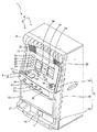
本発明の第1実施の形態について遊技機の一例としてスロットマシンの場合を例に図面に基づいて説明する。図1は、スロットマシン1の前面扉3が閉じた状態を示す斜視図、図2は、スロットマシン1の前面扉3を開いた状態を示した斜視図である。スロットマシン1は、図1に示すように、筐体2と前面扉3とからなる正面視略矩形状の本体4を有している。
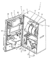
The first embodiment of the present invention will be described with reference to the drawings, taking a slot machine as an example of a gaming machine. 1 is a perspective view showing a state in which the
筐体2は、スロットマシン1の骨格をなす部材であり、図2に示すように、前面側が開放された箱形状を有している。筐体2の内部には、各種の図柄等が表示される複数個の回転ドラム11と、スロットマシン1の主な遊技動作を制御するメイン制御基板50(図4参照乞う)等を収納した制御基板収納ボックス12と、電源スイッチ13a、リセットスイッチ13b、設定キースイッチ13c等を備える電源ボックス13と、遊技価値媒体であるコインMを貯留する補助タンク14a、補助タンク14a内のコインMを排出用通路9からコイン排出口7に支払う支払装置14bと、支払装置14bから支払われるコインを検出するコイン検出部と、ホッパ駆動モータ(図示せず)とを備えたホッパ14等が収容されている。
The
ホッパ14に設けられたコイン検出部は、一対の投光部と受光部(それぞれ図示せず)を有するフォトカプラによって構成されており、本実施の形態においてコイン検出センサ14cを備えている。コイン検出センサ14cは、例えば受光時には「Lo」信号、遮光時には「Hi」信号をそれぞれ出力するように設定されている。
The coin detection unit provided in the
前面扉3は、図2に示すように、左側辺部の上下2カ所がヒンジ5によって筐体2に連結されて取り付けられており、筐体2の前面開放部分を容易に閉塞及び開放できるように構成されている。
As shown in FIG. 2, the
前面扉3は、図1に示すように、上方から下方に向かって順番に表示部3A、操作部3B、貯留部3Cの3つの部分を備えている。表示部3Aには、本発明のコイン排出報知部を構成する種々の装置が配置されている。例えば、前面扉3の上辺に沿って設けられ遊技の進行に伴って点灯・点滅する上部ランプ21と、上部ランプ21の下方位置で左右両側に各々配置されて種々の報知音(効果音)を出力する一対のスピーカ22が設けられている。そして、これら一対のスピーカ22の間に配設されて画像・映像等の種々の情報を表示する液晶ディスプレイ23が設けられている。
As shown in FIG. 1, the
また、表示部3Aの略中央高さ位置には、筐体2内で回転する複数個の回転ドラム11をそれぞれ視認するための透明窓24が設けられており、透明窓24の左側にはコインMのベット数(賭け数)に応じて点灯するベットランプ25が配設されている。そして、表示部3Aの下部には、左側から右側に向かって順番にクレジット枚数表示部26、BB中枚数表示部27、排出枚数表示部28が設けられている。
A
操作部3Bは、表示部3Aの下端で折曲されて手前側に向かって移行するに従って若干の下り傾斜を伴って延在する平面部分Fと、その平面部分Fの手前側の端部で折曲されて下方に向かって垂下する縦壁部分Hを有しており、平面部分Fには、左側位置に1枚用と2枚用のベットボタン31、32が設けられ、その右側近傍位置に3枚用のベットボタン33が設けられている。そして、平面部分Fの右側位置には、コイン投入口34が配設されている。
The
縦壁部分Hの上部には左側から右側に向かって順番に、コインMを貯留するか否かを選択するためのクレジット精算ボタン35、回転ドラム11の回転開始を指示するためのスタートレバー36、回転ドラム11の回転停止を指示するためのストップボタン37が設けられている。
In the upper part of the vertical wall portion H, in order from the left side to the right side, a
クレジット精算ボタン35は、押し操作によって予め設定された枚数、例えば本実施の形態において50枚となるまでの余剰の投入コイン数や入賞時に獲得した獲得コイン数を電子的に記憶する貯留モード(クレジット機能)と、このようにして得たコインを予め設定された枚数まで電子的に記憶せずに実際に支払う支払モードとを切り替えるように構成され、本発明の精算排出開始手段を形成している。例えば、クレジット精算ボタン35が1回操作されると、貯留モードとなり蓄積されたコインの枚数の記憶が開始され、再び操作されると貯留モードが解除されて支払モードとなり記憶させた枚数分のコインが実際に排出される。
The
スタートレバー36は、縦壁部分Hから手前側に向かって突設されており、下方に押し下げる、或いは上方に押し上げることによって操作される。ストップボタン37は、各回転ドラム11に対応する位置にそれぞれ配設されており、押し動作によって操作される。また、操作部3Bの下部には、機種名や遊技に関わるキャラクタ等が表示された表示プレート15等が設けられている。
The
貯留部3Cは、操作部3Bの下方位置で左右方向に亘って延在するように配置形成されており、コイン排出口7から払い出されたコインMを受けて貯留するコイン受け皿16や灰皿17等が設けられている。
The storage unit 3C is arranged and formed so as to extend in the left-right direction at a position below the
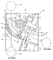
次に、コイン投入口34から投入されたコインMが供給されるセレクタ40について説明する。図3は、セレクタ40の内部構造を示す図である。
Next, the
セレクタ40は、前面扉3の背面に沿って延在するように配置され、セレクタボディ41には、コイン投入口34から送出されたコインMを貯留用通路8に導くためのコイン案内路42が設けられている。
The
コイン案内路42は、図3に矢印Aで示すように、セレクタボディ41のボディ上面左側部分から垂下してセレクタボディ41の略中央高さ位置でボディ右側に向かってカーブし、更に矢印Bで示すように所定の傾斜角で右側面の下部まで延在しており、コインMが一列で通行することができるように形成されている。本実施の形態では、セレクタボディ41から図の手前側に突出する突条42aによって構成されており、コインMは、突条42a上を転がりながら下流方向に流れる。
As shown by an arrow A in FIG. 3, the
コイン案内路42の途中位置には、図中に矢印Cで示すように、コイン案内路42から分岐して排出用通路9に連通する分岐通路43が形成されており、コイン案内路切替手段44によってコインMを貯留用通路8と排出用通路9のいずれに供給するかを選択することができるように構成されている。
A
コイン案内路切替手段44は、コイン案内路42に対して出没可能な切替片44aと、この切替片44aを動作させるためのソレノイド(図示せず)とを備えており、ソレノイド非励磁時にはコイン案内路42内に切替片44aを突出させることによって貯留用通路8へのコインMの流れを阻害し、コインMを突条42aの上から図中の手前側に移動させて下方に落下させて分岐通路43に誘導し、分岐通路43から排出用通路9に導いて、前面扉3のコイン排出口7からコイン受け皿16に排出させる。また、ソレノイド励磁時にはコイン案内路42外に切替片44aを没入させて、コインMをコイン案内路42に沿って移動させて、貯留用通路8に導き、筐体2の内部に収容されたホッパ14に供給する。
The coin guide path switching means 44 includes a
コイン案内路42の下流側位置には、コインMの通過を検出するコイン通過検出部45が設けられている。コイン通過検出部45は、通過するコインMを介して両側に一対の投光部と受光部(それぞれ図示せず)を有するフォトカプラによって構成されており、本実施の形態において第1投入コイン通過検出センサ45aと第2投入コイン通過検出センサ45bを備えている。第1投入コイン通過検出センサ45aと第2投入コイン通過検出センサ45bは、少なくとも通過する1枚のコインMを同時に検出しうる程度に近接した状態で上流側と下流側に並設され、例えば各投入コイン通過検出センサ45a、45bは受光時には「Lo」信号、遮光時には「Hi」信号をそれぞれ出力するように設定されている。
A coin
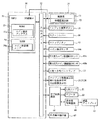
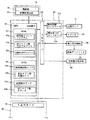
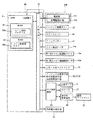
次に、制御基板収納ボックス12内に配設されているスロットマシン1のメイン制御基板50等について図4及び図5に基づいて説明する。図4は、スロットマシン1のメイン制御基板50の構成を説明するブロック図、図5は、スロットマシン1のサブ制御基板60の構成を説明するブロック図である。
Next, the
メイン制御基板50は、遊技の主な制御処理を行うものであり、演算装置である1チップマイコンとしてのMPU51と、そのMPU51に接続されると共にセンサ類やスイッチ類などの各種の入出力手段に接続された入出力ポート52が搭載され、本発明のメイン制御部を構成している。
The
MPU51には、MPU51により実行されるコイン検出プログラム53a等の制御プログラムや固定値データを記憶したROM53と、そのROM53内に記憶される制御プログラムの実行にあたって各種のデータを一時的に記憶するためのメモリであるRAM54と、割込回路、タイマ回路、データ送受信回路等の各種回路等が内蔵されている。
In the MPU 51, a
コイン検出プログラム53aは、例えばクレジット精算ボタン35が操作されてコインの排出が開始されるときに、ホッパ14のコイン検出センサ14cから出力された検出信号に基づいてコインと認識して、コイン排出コマンドを生成するように構成されている。
The
RAM54は、クレジット精算ボタン35の操作により貯留モードとされたときに、セレクタ40の第1投入コイン通過検出センサ45a、第2投入コイン通過検出センサ45bから出力された検出信号に基づき認識したコインの枚数及び入賞により獲得したコインの枚数を予め設定された枚数、例えば50枚までの枚数を電子的に記憶するコイン数記憶エリア54aを有している。そして、図6〜図9に示されたフローチャートのプログラムは、制御プログラムの一部としてROM53内に記憶されている。
The
入出力ポート52には、クレジット精算ボタン35、スタートレバー36、ストップボタン37、コイン検出センサ14c、第1投入コイン通過検出センサ45a、第2投入コイン通過検出センサ45b、1〜3枚ベットランプ25、クレジット枚数表示部26、BB中枚数表示部27、払出枚数表示部28、サブ制御基板60、外部集中端子板67等が接続されている。
The input /
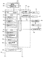
サブ制御基板60は、メイン制御基板50と別個に設けられメイン制御基板50から送信されるコマンドを受信して遊技以外の補助的な制御処理を行うものであり、本発明のサブ制御部を構成する。サブ制御基板60は、上部ランプ21による点灯・点滅及びスピーカ22から報知音等の出力制御、表示用制御基板66を制御して液晶ディスプレイ23上に演出表示等を行うように構成されている。
The
サブ制御基板60には、演算装置である1チップマイコンとしてのMPU61と、そのMPU61に接続されると共にセンサ類やスイッチ類などの各種の入出力手段に接続され、メイン制御基板50から送信されるコマンドを受信する入出力ポート62が搭載されている。
The
MPU61には、MPU61により実行される遊技数カウントプログラム63a、排出コイン数判定プログラム63b、報知制御プログラム63c等の制御プログラムや基準遊技数、基準排出コイン数、標準コイン異常排出報知時間、上部ランプ用発光テーブル、報知音テーブル等の固定値データを記憶したROM63と、そのROM63内に記憶される制御プログラムの実行にあたって各種のデータ、例えばコマンド間遊技数(クレジット精算ボタン35が操作されてから次にクレジット精算ボタン35が操作されるまでに行われた遊技数)や排出コイン数(クレジット精算ボタン35に基づき排出されているコインの枚数)を一時的に記憶するためのメモリであり、遊技数記憶エリア64a、排出コイン数記憶エリア64bを有するRAM64と、割込回路、タイマ回路、データ送受信回路等の各種回路と、メイン制御部50から送信されてきた遊技数カウント用コマンドに基づき前の精算排出開始コマンドから次の精算排出開始コマンドの間の遊技数であるコマンド間遊技数をカウントし、本発明の遊技数カウント部を構成する遊技数カウンタ65aやコイン排出コマンドに基づきコインの排出枚数をカウントする排出コイン数カウンタ65b等の各種カウンタ等が内蔵されている。図10〜図17に示されたフローチャートのプログラムは、制御プログラムの一部としてROM63内に記憶されている。
The
入出力ポート62には、発光制御コントローラ21a、報知音出力コントローラ22a、表示用制御基板66、外部集中端子板68等が接続されており、表示用制御基板66との間ではデータ等を双方向に送受信可能に構成されている。発光制御コントローラ21aは、MPU61によりROM63の上部ランプ用発光テーブルから読み出された上部ランプ用発光データに基づいて上部ランプ21のLEDを発光制御するように構成され、上部ランプ21と共に本発明の照明手段を形成する。報知音出力コントローラ22aは、MPU61によりROM63の報知音テーブルから読み出された報知音データに基づいてスピーカ22から報知音を出力するように構成され、スピーカ22と共に本発明の報知音出力手段を形成する。
The light
電源基板70は、電源ボックス13内に設けられており、メイン制御基板50の他に、スロットマシン1の各電子機器に駆動電力を供給する電源部71と、電源断の発生を監視する停電監視回路72等の各種回路を備えている。スロットマシン1の電源オフ後には、電源基板70の電源部71からRAM54にバックアップ電圧が供給される。
The
停電監視回路72は、停電等の発生による電源断時(電源スイッチ13aのオフによる電源断を含む)に、メイン制御基板50のNMI端子、入出力ポート52及びサブ制御基板60のNMI端子へ停電信号を出力するための回路である。停電監視回路72は、電源基板70から出力される最も大きい電圧である直流安定24ボルトの電圧を監視し、この電圧が22ボルト未満になった場合に停電(電源断)の発生と判断して、停電信号を出力するように構成されている。停電信号の出力に基づいて、メイン制御基板50は、停電の発生を認識し、停電時処理を実行するように構成されている。なお、停電監視回路72の停電信号は、メイン制御基板50及びサブ制御基板60のNMI端子に代えて、INT端子に入力されるように構成しても良い。
The power
また電源基板70は、直流安定24ボルトの電圧が22ボルト未満になった後においても、停電時処理の実行に充分な時間の間、制御系の駆動電圧である5ボルトの出力を正常値に維持するように構成されている。例えば、本実施の形態において30msecの間は、駆動電源が出力されるように構成されている。よって、メイン制御基板50は、停電時処理を正常に実行することができる。また、停電監視回路72を、電源基板70ではなく、例えばメイン制御基板50に設けるようにしても良い。
Further, the
次に、図6〜図9に示すフローチャートを参照して、メイン制御基板50で行われる各処理について説明する。メイン制御基板50で行われる処理として、電源投入に伴い起動されるメイン処理と、定期的(本実施の形態では、1.49ms周期)に起動されるタイマ割込処理と、NMI端子への停電信号の入力により起動されるNMI割込処理が設定されている。以下の説明では、便宜上、NMI割込処理とタイマ割込処理について説明し、その後にメイン処理について説明する。
Next, each process performed on the
図6は、NMI割込処理の一例を示すフローチャートである。停電の発生等により電源が遮断されると、停電監視回路72から停電信号が出力されてメイン制御基板50のMPU51に対して出力される。NMI端子を介して停電信号を受信したMPU51によりNMI割込処理が即座に実行される。なお、上述したようにメイン制御基板50においてNMI端子に代えてINT端子を設ける構成とした場合には、停電監視回路72の停電信号はINT端子に入力される。
FIG. 6 is a flowchart illustrating an example of the NMI interrupt process. When the power is shut off due to the occurrence of a power failure or the like, a power failure signal is output from the power
NMI割込処理では、まずステップS101において、MPU51内に設けられた使用レジスタのデータをRAM54内に設けられたスタックエリアへ退避する。次に、ステップS102では、停電フラグをRAM54内に設けられた所定のワークエリアにセットする。その後、ステップS103にてスタックエリアへ退避させたデータを再びMPU51に搭載の使用レジスタに復帰させて本ルーチンの処理を終了する。なお、使用レジスタのデータを破壊せずに停電フラグをセット処理可能な場合には、スタックエリアへの退避及び復帰処理を省略することができる。
In the NMI interrupt processing, first, in step S101, the data in the used register provided in the MPU 51 is saved in the stack area provided in the RAM. Next, in step S102, a power failure flag is set in a predetermined work area provided in the
図7は、メイン制御基板50で定期的(本実施の形態では1.490ms毎)に実行されるタイマ割込処理のフローチャートである。このタイマ割込処理では、例えば、クレジット精算ボタン35、スタートレバー36、ストップボタン37等の操作状態読み込み処理、ホッパ14のコイン検出センサ14c、セレクタ40のコイン通過検出センサ45a、45b等の各種センサの監視処理、入賞抽選結果コマンド等のコマンド送信処理等が行われる。
FIG. 7 is a flowchart of a timer interrupt process that is periodically executed by the main control board 50 (every 1.490 ms in the present embodiment). In this timer interruption process, for example, the operation state reading process of the
まずステップS201に示すレジスタ退避処理では、通常処理(図9参照乞う)で使用している全レジスタの値をスタックエリアへ退避させる。ステップS202では、停電フラグがオンされているか否かを確認し、停電フラグがオンされている場合(ステップS202においてYes)、図6のNMI割込処理で説明した通り停電の発生であるので、ステップS203に進み停電時処理を実行する。 First, in the register saving process shown in step S201, the values of all the registers used in the normal process (see FIG. 9) are saved in the stack area. In step S202, it is confirmed whether or not the power failure flag is turned on. If the power failure flag is turned on (Yes in step S202), the power failure has occurred as described in the NMI interruption process of FIG. It progresses to step S203 and the process at the time of a power failure is performed.
本実施の形態において、ステップS203の停電時処理は、タイマ割込処理のうち特にレジスタ退避処理(ステップS201)の直後に行われることから、他の割込処理を中断することなく実行可能である。従って、例えば各種のコマンドの送信処理中やスイッチの状態(オン又はオフ)の読み込み処理中等のように、各々の処理に割り込んで停電時処理が実行されることはないことから、このようなタイミングで停電時処理が実行されることを考慮した停電時処理のプログラムを作成する必要がない。これにより、停電時処理のプログラムを簡略化して、プログラム容量を削減可能となる。 In the present embodiment, the power failure process in step S203 is performed immediately after the register saving process (step S201) in the timer interrupt process, and therefore can be executed without interrupting other interrupt processes. . Therefore, the power failure process is not executed by interrupting each process, such as during the transmission process of various commands or the reading process of the switch state (ON or OFF). Therefore, it is not necessary to create a power failure processing program that takes into account that power failure processing is executed. This simplifies the power failure processing program and reduces the program capacity.
一方、停電フラグがオンされていなければ(ステップS202においてNo)、停電は発生していないので、ステップS204以降の処理が行われる。 On the other hand, if the power failure flag is not turned on (No in step S202), no power failure has occurred, and therefore, the processing after step S204 is performed.
ステップS204では、誤動作の発生を監視するウォッチドッグタイマの値を初期化するウォッチドッグタイマクリア処理を行う。そして、ステップS205では、MPU51自身に対して割込許可を出す割込終了宣言処理を行う。ステップS206では、筐体2に収納された各回転ドラム11の回胴モータ(ステッピングモータ)を回転駆動させる回胴モータ制御処理を行う。ステップS207では、各種スイッチのオン・オフ状態を読み込むスイッチ状態読み込み処理を行う。
In step S204, a watchdog timer clear process for initializing the value of the watchdog timer that monitors the occurrence of malfunction is performed. In step S205, an interrupt end declaration process for giving an interrupt permission to the MPU 51 itself is performed. In step S206, a rotating motor control process for rotating the rotating motor (stepping motor) of each
ステップS208では、各種センサの状態を読み込んで、読み込み結果が正常であるか否かを監視するセンサ監視処理を行う。ステップS209では、各カウンタやタイマの値を減算するタイマ減算処理を行う。ステップS210では、IN・OUTカウンタ処理を行う。ステップS211では、サブ制御基板60へコマンドを送信するコマンド出力処理を行う。
In step S208, sensor monitoring processing is performed to read the state of various sensors and monitor whether the reading result is normal. In step S209, a timer subtraction process for subtracting the value of each counter or timer is performed. In step S210, IN / OUT counter processing is performed. In step S211, command output processing for transmitting a command to the
ステップS212において、クレジット枚数表示部26、BB中枚数表示部27及び排出枚数表示部28にそれぞれ表示されているセグメントデータを設定するセグメントデータ設定処理を行ってから、ステップS213において、セグメントデータを各表示部26〜28にそれぞれ供給して数字、記号等を表示するセグメントデータ表示処理を行う。ステップS214では、入出力ポート52から出力データを出力するポート出力処理を行う。
In step S212, a segment data setting process for setting the segment data displayed in the credit number display unit 26, the BB medium number display unit 27, and the discharge number display unit 28 is performed. Segment data display processing for displaying numbers, symbols, and the like is performed by supplying the data to the display units 26 to 28, respectively. In step S214, port output processing for outputting output data from the input /
そして、これらの処理の実行後には、ステップS215において、スタックエリアへ退避させた各レジスタの値をそれぞれの対応のレジスタへ復帰させ、ステップS216にて次回のタイマ割込の発生を許容する割込許可処理を行って、タイマ割込処理を終了する。 After execution of these processes, in step S215, the value of each register saved in the stack area is returned to the corresponding register, and in step S216, an interrupt that allows generation of the next timer interrupt is permitted. The permission process is performed and the timer interrupt process is terminated.
図8は、電源投入時にメイン制御基板50で実行される起動処理のフローチャートである。電源スイッチ13bがオン操作されてスロットマシン1の電源が投入されると(停電からの復旧による電源入を含む)、この処理が実行される。まず、初期化処理として、スタックポインタの値を設定し(ステップS301)、割込モードを設定し(ステップS302)、そしてCTC・内蔵レジスタの設定処理を行う(ステップS303)。
FIG. 8 is a flowchart of the startup process executed by the
初期化処理が終了すると、ステップS304では、設定キーが設定キースイッチ13cに挿入されているか否かを判定する。設定キースイッチ13cがオンされている場合(ステップS304においてYes)、ステップS305に進み、強制的RAMクリア処理を実行して、RAM54の全ての内容を0クリアする。その後、ステップS306で6段階確率設定処理を実行する。6段階確率設定処理では、遊技の当選確率が6段階に切り替えられ、後述する遊技に関わる主要な制御を行う通常処理(図9参照乞う)に移行する。
When the initialization process is completed, in step S304, it is determined whether or not a setting key is inserted in the setting
一方、ステップS304において設定キースイッチ13cがオンされていない場合(ステップS304においてNo)、ステップS307に進み、6段階確率設定値の設定値が正常かどうかを判定する。具体的には、1〜6の範囲の正常な設定値であり、0又は7以上でないかどうかを判定する。設定値が正常である場合(ステップS307においてYes)、ステップS308に進み、復電フラグがセットされているかどうかを確認する。復電フラグを確認した場合(ステップS308においてYes)、ステップS309に進み、RAM判定値が正常であるかを確認する。具体的には、RAM54のチェックサム値を調べ、RAM判定値を加味したチェックサムの値が正常の0であるかどうかを確認する。RAM判定値を加味したチェックサムの値が0である場合(ステップS309においてYes)、RAM54のデータは正常であると判定する。
On the other hand, if the setting
ステップS309においてRAM判定値が正常であると判定した場合、ステップS310に進み、バックアップエリアに保存されたスタックポインタの値をMPU51のスタックポインタに書き込み、スタックの状態を電源断の前の状態に復帰させる。次に、ステップS311において、復電処理の実行を伝える復電コマンドを設定する。その後、ステップS312にて遊技状態として打ち止め及び自動精算設定処理を行い、続いてステップS313にてクレジット精算ボタン35等のスイッチ状態の初期化を行う。以上の処理の終了後、ステップS314において停電フラグをリセットし、電源断前の番地に戻る。具体的には、タイマ割込処理に復帰し、ウォッチドッグタイマクリア処理(ステップS204)が実行される。
If it is determined in step S309 that the RAM determination value is normal, the process proceeds to step S310, where the stack pointer value stored in the backup area is written to the stack pointer of the MPU 51, and the stack state is restored to the state before the power-off. Let Next, in step S311, a power recovery command that tells execution of power recovery processing is set. Thereafter, in step S312, the game state is stopped and automatic settlement setting processing is performed, and then in step S313, the switch state of the
一方、ステップS307〜ステップS309のいずれかのステップにおいてNoであった場合、RAM54のデータが破壊されている等の異常が発生しているので、ステップS315以降の処理に進み、動作禁止処理を行う。具体的には、ステップS315において、次回のタイマ割込処理を禁止し、その後、ステップS316において、入出力ポート52内の全ての出力ポートをクリアして、入出力ポート52に接続された全てのアクチュエータをオフ状態に制御する。そして、ステップS317に進んで、エラー表示を行ってバックアップエラーの発生を報知して、無限ループに入る。
On the other hand, if the answer is No in any of steps S307 to S309, an abnormality such as destruction of data in the
図9は、図8に示すフローチャートに基づき電源投入後のメイン処理が行われた後にメイン制御基板50のMPU51により行われる通常処理のフローチャートである。本ルーチンは、メイン制御基板50のMPU51により繰り返し行われるスロットマシン1の主要な制御処理であり、電源投入後に設定キースイッチ13cがオフの場合(ステップS304においてNo)、前回の電源断時の番地に復帰する。一方、電源の投入後に設定キースイッチ13cがオンされている場合(ステップS304においてYes)、図8に示す強制的RAMクリア処理(ステップS305)及び6段階確率設定処理(ステップS306)が行われてから本ルーチンのステップS401に移行する。
FIG. 9 is a flowchart of a normal process performed by the MPU 51 of the
まずステップS401では、初期化処理として本ルーチンにおいて割込を許可する割込許可の設定が行われて、ステップS402において遊技状態として打ち止め及び自動精算設定処理が行われ、例えば電源ボックス13に設けられた打ち止め有無スイッチ、自動精算有無スイッチ(それぞれ図示せず)の状態をRAM54の所定領域に格納してから、以下に説明する繰り返しルーチンに移行する。
First, in step S401, an interrupt permission setting for permitting an interrupt is performed in this routine as an initialization process, and in step S402, a stop and automatic settlement setting process is performed as a gaming state, which is provided in the
ステップS403ではRAM初期化処理が行われ、RAM54において1回の遊技で使用される領域(RAM54の1回遊技用領域)をクリアする処理が行われる。本ステップでは、例えば、発生したエラーに関する情報、入賞図柄(ハズレを含む)、入賞ライン、入賞獲得コイン数等の入賞に関する情報、遊技で用いた乱数、回転ドラム11の回転に関する情報等がクリアされる。
In step S403, a RAM initialization process is performed, and a process of clearing an area used for one game in the RAM 54 (one-game area in the RAM 54) is performed. In this step, for example, information relating to the error that has occurred, winning symbols (including loss), winning lines, winning information such as the number of winning winning coins, random numbers used in the game, rotating
RAM54の初期化処理が行われると、ステップS404に進み、スタートレバー36の操作が行われたかを判定する始動装置ON待ち処理が行われる。本ステップで、スタートレバー36が操作されていない場合、MPU51は制御処理を行うことなく本ルーチンは待機する。ステップS404の処理では、スタートレバー36の操作が行われるまでルーチンが待機しているので、種々の処理が行われる。
When the initialization process of the
例えば、上述のようにスタートレバー36が操作されないことにより所定時間に亘って遊技が行われなかった場合、液晶ディスプレイ23上で行われるデモに移行するためのタイマ設定処理を行う。また、当該遊技が再遊技である場合、コインの自動投入処理を行う(クレジット枚数表示部26に表示されている数値は変わらない)。一方、再遊技でない場合には、ホッパ14の横に設けられた満杯センサ(図示せず)からの検出信号に基づきコインの満杯を判定する処理を行う。
For example, if the game is not performed for a predetermined time because the
このような処理の後、タイマ割込処理の中でセンサー監視処理が行われており(ステップS208)、上述したようにホッパ14のコイン検出センサ14c、スタートレバー36の押し上げ操作又は押し下げ操作を検出するセンサ、ストップボタン37の操作を検出するセンサ、セレクタ40の第1投入コイン通過検出センサ45aと第2投入コイン通過検出センサ45b、補助タンク14aの補助タンクセンサ等を監視していることから、これらのセンサで異常が発生した場合には、エラー報知を行うためのセンサエラー報知処理を行う。
After such processing, sensor monitoring processing is performed in the timer interrupt processing (step S208), and as described above, the push-up operation or push-down operation of the
センサエラーが発生していないか、又は所定のセンサーエラー報知処理を行った後、クレジット精算ボタン35が操作されたのかどうかの判断がなされる。クレジット精算ボタン35が操作されたものと判定した場合、コインの排出開始にかかる精算排出開始コマンドを生成し、貯留コインの排出を行うべく貯留コイン排出処理に移行する。
It is determined whether or not a sensor error has occurred or whether or not the
MPU51により行われる貯留コイン排出処理では、例えばRAM54のコイン数記憶エリア54aに電子的に記憶されているコイン数を読み出し、読み出した数値をホッパ14のコイン検出センサ14cの検出信号に基づいて1ずつ減算していく。そして、コイン数記憶エリア54aのコイン数が1ずつ減算する毎にコイン排出コマンドをサブ制御基板60に送信できるようにRAM54のリングバッファに格納する。そして、読み出されたコイン数記憶エリア54aの数値がゼロとなったときに、ホッパ14から排出が終了したものと認識する。このとき、コインの精算終了にかかる精算排出終了コマンドを生成してRAM54に格納する。
In the stored coin discharge process performed by the MPU 51, for example, the number of coins stored electronically in the coin
或いは、MPU51によりコイン数記憶エリア54aのコイン数が読み出されたときに、MPU51はホッパ14から排出させるコインの枚数を認識できるので、読み出した値をRAM54のリングバッファにそのまま格納して、コイン排出コマンドとしてサブ制御基板60に送信し、コインが1枚ずつ減算する毎のコマンドを中止するようにしても良い。或いは、MPU51は、精算排出開始コマンドだけをサブ制御基板60側に送信し、精算排出開始コマンドを受けた後の時間の管理をサブ制御基板60側で行う制御手法としても良い。
Alternatively, when the number of coins in the coin
そして、コイン投入口34からコインの投入があった場合には、投入枚数の判定処理がなされる。例えば、セレクタ40の第1投入コイン通過検出センサ45aと第2投入コイン通過検出センサ45bの検出信号に基づき適正な検出信号であれば、1枚のコインとして認識する。また、この段階で、コイン排出報知等の所定の報知演出が行われている場合、MPU51はコインを認識すると、所定の報知演出を強制的に終了させるコマンド(例えば、コイン排出報知強制終了コマンド)を生成する。
When a coin is inserted from the
そして、例えば、コイン投入口34から1枚〜3枚のコインが投入されるか、又はいずれかのベットボタン31〜33が操作されて、投入されたコインの枚数が規定数に到達した後、スタートレバー36の操作がなされたものと判定した場合には、スタートレバー36が操作された旨の信号がRAM54のリングバッファに格納される。
For example, after 1 to 3 coins are inserted from the
スタートレバー36が操作された旨の信号は、メイン制御基板50側において1回の遊技で必ず生成されて、所定のタイミング(ステップS211)でサブ制御基板60側に送信される信号であることから、本発明の遊技数カウント用コマンドを形成する。本発明の遊技数カウント用コマンドは、1回の遊技でサブ制御基板60側に必ず送信されればどのような信号であっても良く、例えばストップボタン37が操作された旨の信号も本発明の遊技数カウント用コマンドとするようにしても良い。
The signal indicating that the
また、スタートレバー36の操作がなされたものと判定した場合には、コインの受け入れを禁止する処理が行われる。例えば、セレクタ40の切替片44aをコイン通路42に突出させて、コイン受入禁止中に投入されたコインを排出用通路9に誘導し、前面扉3のコイン払出口7からコイン受け皿16に排出させる処理が行われる。或いは、ベットボタン31〜33のいずれかのベットボタンが操作されても、ベットボタンの操作と判定しないような処理が行われる。そして、コイン受入禁止処理を行って本ステップの処理を終了する。或いは、この段階でも未だにスタートレバー36の操作がなされていない場合には、上述のセンサエラー処理から繰り返して行う。
If it is determined that the
このようにして、エラーが発生するか、コインの精算排出が開始されるか、セレクタ40の切替片44aの出没処理が行われるか、又はコインの投入等が行われると、サブ制御基板60にコマンドを送信するために各々の処理で生成されたコマンドがRAM54のリングバッファに格納される。
In this way, when an error occurs, the coin settlement is started, the
ステップS404でスタートレバー36が操作されると、ステップS405に進み、乱数作成処理が行われる。具体的には、ステップS404でスタートレバー36の操作がMPU51により認識されると、メイン制御基板50に搭載された発振器の所定周期に基づきカウントするフリーランニングカウンタ(図示せず)のカウント数をハードウエア的にラッチし、所定のタイミングでMPU51が乱数値として読み出すことによって作成される。このようにしてMPU51に読み出された乱数値はRAM54に格納される。
When the
乱数作成処理が行われると、ステップS406に進んで6段階確率設定処理(ステップS306)で設定された設定値に応じて決められた当選確率に基づき内部抽選処理が行われる。内部抽選処理とは、ステップS405においてRAM54に格納された乱数値に基づいて、ROM53に予め設定されている入賞テーブルの数値範囲との対比によって入賞しているのか否かを決定する処理である。
When the random number generation process is performed, the process proceeds to step S406, and the internal lottery process is performed based on the winning probability determined according to the set value set in the six-stage probability setting process (step S306). The internal lottery process is a process of determining whether or not a winning is made based on the random number value stored in the
内部抽選処理で使用される入賞テーブルには、コインの払い出しが比較的多いビッグボーナス(以下、BBと称する)、レギュラーボーナス(以下、RBと称する)等の特別役、これらの入賞役と対称的に、コインの払い出しが比較的少ないチェリー等の一般役(通常、複数種類の入賞役が設定され「小役」と称されている)、このような入賞役に該当せずコインの払い出しが行われないハズレ、そしてコインの払い出し自体は行われないが、コインを投入することなく次の遊技を一回に限り行うことができる再遊技役等の複数種類の入賞役が設定されている。各々の入賞役に対して、その入賞役に当選する割合が、フリーランニングカウンタにより生成される所定の範囲の乱数に所定の数値範囲にて設定されている。各々の入賞役は、6段階確率設定処理(ステップS306)において設定された当選確率(「設定1」〜「設定6」)に基づいて数値範囲を変えて設定されている。例えば、当選確率の設定値の数字が小さくなるほど、ハズレ以外の入賞役の数値範囲が狭くなるように設定されている。そして、現在設定されている設定値と、内部抽選によって得られた結果を入賞役抽選コマンドとしてRAM54の所定のワークエリアに格納する。そして、入賞役抽選コマンドについても1回の遊技でサブ制御基板60側に必ず送信される信号であることから、本発明の遊技数カウント用コマンドとしても良い。
The winning table used in the internal lottery process includes a special bonus such as a big bonus (hereinafter referred to as BB) and a regular bonus (hereinafter referred to as RB), which are relatively large in payout of coins, and is symmetrical with these winning bonuses. In addition, a general role such as cherries with a relatively small amount of coins to be paid out (usually multiple types of winning roles are set and referred to as “small roles”), and coins are not paid out. There are multiple types of winning combinations such as a re-gamer that can perform the next game only once without inserting coins. For each winning combination, the ratio of winning the winning combination is set to a predetermined range of random numbers generated by a free running counter within a predetermined numerical range. Each winning combination is set by changing the numerical range based on the winning probabilities (“Setting 1” to “Setting 6”) set in the six-stage probability setting process (Step S306). For example, the smaller the numerical value of the winning probability setting value, the narrower the numerical value range of winning combinations other than the loss is set. Then, the currently set value and the result obtained by the internal lottery are stored in a predetermined work area of the
MPU51において内部抽選処理が行われると、ステップS407に進んで回胴回転初期化処理が行われる。回胴回転初期化処理では、ステップS406の内部抽選結果に基づき回転ドラム11の回転制御で用いられるドラム制御テーブルの中からテーブル番号を決定する。
When the internal lottery process is performed in the MPU 51, the process proceeds to step S407, and the rotation rotation initialization process is performed. In the rotation rotation initialization process, a table number is determined from the drum control table used for the rotation control of the
そして、ステップS408において前回の回転ドラム11の回転開始から4.1秒が経過したかどうかの4.1秒経過待ち処理が行われ、具体的には、設定された4.1秒タイマの数値がゼロとなっているかどうかの確認がなされる。本ステップで4.1秒が経過していない場合には、現在の遊技状態を表す状態コマンド(以下、単に「状態コマンド」と称する。)をRAM54に格納し、上部ランプ21等を通じてウエイト処理(即ち、4.1秒待ち)を報知する。
In step S408, a 4.1 second elapsed waiting process is performed to determine whether 4.1 seconds have elapsed since the start of the previous rotation of the
一方、4.1秒経過している場合には、次回の4.1秒経過待ち処理のために4.1秒タイマを設定すると共に、状態コマンドをRAM54に格納し、タイマ割込制御処理の中で投入コインの枚数を出力できるように(ステップS210)所定の設定を行う。
On the other hand, if 4.1 seconds have elapsed, a 4.1 second timer is set for the next 4.1 second waiting process, a status command is stored in the
その後、回転ドラム11のモータ制御初期化処理が行われ、回転ドラム11の回転に関するRAMの所定領域を回転開始用に設定する処理が行われる。このような設定が行われると、ステップS206の回胴モータ制御処理に基づき回胴用モータ(ステッピングモータ)の加速処理が実際に開始され、回転ドラム11の回転が開始される。
Thereafter, motor control initialization processing of the
回転ドラム11が実際に回転開始すると、ステップS409に進み回胴回転処理が行われる。本ステップでは、回胴回転処理で用いるRAMの所定領域を初期化し(上述のステップS408)、回胴回転情報コマンドと状態コマンドを格納し、上述の回胴用モータの加速処理に基づき回転ドラム11が正常回転となるまで待機する。回転ドラム11の回転が正常回転か否かの判断は、回胴モータ制御処理(ステップS206)に基づき加速処理が終了した時点でのインデックス検出によって行われる。インデックス検出に基づき回転ドラム11の回転が正常回転になったものと判定された場合、スロットマシン1の設定状態が後述する所定の停止操作により回転ドラム11の回転を停止させることができる状態であると判定し、回転停止可能である旨の報知を行う。
When the
回転ドラム11の回転が停止可能状態にある旨の報知は、ストップボタン37に内蔵されたランプの発光手法を変化させることにより行われる。例えば、ストップボタン37のランプの発光させる色を変更したり、消灯状態であったランプを点灯状態にすることにより報知が行われる。なお、このような報知は、ストップボタン37の操作が有効となったストップボタンのみにおいて行われる。
The notification that the rotation of the
そして、有効となったストップボタン37が実際に操作されると、ステップS406の内部抽選処理で決定された停止図柄の組み合わせをステップS407で設定したテーブル番号に基づき回転ドラム11を停止させる処理を行う。本ステップにおいて回転ドラム11を、テーブル番号で設定されているとおりに停止させることは必ずしも必要なく、例えばストップボタン37の停止順序や停止位置に応じてテーブル番号を変更したり、強制的に回転ドラム11を引き込むような処理を行うように回転ドラム11のステッピングモータの駆動制御を行う。回転ドラム11が停止すると、停止した回転ドラム11に対応したストップボタン37の操作許可が無効となる。
When the activated
このような回転ドラム11の停止処理は、全ての回転ドラム11が停止するまで行い、回転ドラム11の回転が停止する毎に対応するストップボタン37の操作許可を無効にして、全てのストップボタン37の操作許可が無効となって時点で本ステップを終了する。ステップS409では、回転ドラム11のいずれかのドラムが停止する毎に、回胴回転情報コマンド、停止図柄コマンドをRAM54に格納する。
Such stop processing of the
全ての回転ドラム11が停止すると、ステップS410に進んで入賞図柄判定処理が行われ、視認窓24を通じて認識可能な回転ドラム11の図柄がどのような組み合わせにて停止しているのかを判定する。
When all the
本ステップでは、まず遊技状態に応じて有効ラインを判断する。具体的には、5本ある有効ラインのうちのどのラインが有効なのか遊技状態に基づき判断する。例えば、遊技状態が通常遊技である場合、ベット数に応じて有効ラインが1ライン〜5ラインまでとなり、例えばベット数が3枚であると5ラインの全てが有効ラインとなる。また、遊技状態が役物遊技である場合、ベット数は1枚で1ラインのみが有効となる。 In this step, first, an active line is determined according to the gaming state. Specifically, which of the five active lines is effective is determined based on the gaming state. For example, when the gaming state is a normal game, the effective lines are 1 to 5 lines according to the number of bets. For example, when the number of bets is 3, all 5 lines are effective lines. When the gaming state is an accessory game, the number of bets is one and only one line is valid.
有効ラインの本数を認識すると、視認窓24を通じて認識可能な図柄(9マス分)が有効ライン上でどのような組み合わせにて停止しているのかを各有効ライン毎に判定する。視認窓24における絵柄は、各リールの各々の絵柄に付されている図柄番号に基づいて認識される。
When the number of effective lines is recognized, it is determined for each effective line which combination of symbols (for 9 squares) that can be recognized through the
各有効ライン毎の図柄の組み合わせを認識し、図柄が所定の入賞図柄にて揃っている場合には、入賞図柄として設定し、その入賞図柄に対応した払出枚数をホッパ14から払い出すことができるように所定の設定を行う。このとき、有効ライン上に複数の入賞図柄が揃っている場合には、各々の入賞図柄に対応した払出枚数を順次加算していく処理が行われるが、スロットマシン1は1回の払出枚数として規定数(通常15枚)のコインだけを払い出すように構成されているので、払出枚数を加算して規定数を超過したときには払出枚数を規定数に変更する処理が行われる。また、ステップS406の内部抽選処理により決定した入賞図柄以外の図柄が有効ライン上に停止した場合には、エラーとして認識する。 When a combination of symbols for each active line is recognized and the symbols are arranged in a predetermined winning symbol, it can be set as a winning symbol and the payout number corresponding to the winning symbol can be paid out from the hopper 14 A predetermined setting is performed as follows. At this time, when a plurality of winning symbols are arranged on the active line, a process of sequentially adding out the number of payouts corresponding to each winning symbol is performed. Since only a prescribed number (usually 15) of coins is paid out, when the prescribed number is exceeded by adding the number of paid-out coins, a process of changing the paid-out number to the prescribed number is performed. Further, when a symbol other than the winning symbol determined by the internal lottery process in step S406 stops on the active line, it is recognized as an error.
ステップS410において、認識した入賞図柄、入賞図柄が揃っていた有効ライン及びエラーが発生した場合にはエラーをそれぞれ入賞図柄コマンド、入賞ラインコマンド及びエラーコマンドとしてRAM54に格納する。
In step S410, if a recognized winning symbol, a valid line having a winning symbol, and an error occur, the error is stored in the
次いで、ステップS411に進み、ステップS410において設定された払出枚数に基づき獲得したコインの払い出しが行われる。ステップS410において払出枚数が0枚である場合、ステップS411は行われることなく次のステップにスキップされる。 Next, the process proceeds to step S411, and coins acquired based on the payout number set in step S410 are paid out. When the payout number is 0 in step S410, step S411 is skipped to the next step without being performed.
クレジット精算ボタン35の操作により貯留モードとなっている場合には、スロットマシン1のクレジット機能により、RAM54のコイン数記憶エリア54aに50枚になるまで電子的に蓄積していき(クレジット枚数表示部26に表示されている数値に1ずつ加算されて表示される)、50枚を超えた時点でホッパ14からコインを払い出す処理を行う。一方、支払モードとなっている場合には、本ステップにおいて認識した払出枚数分のコインがホッパ14から払い出される。
When the storage mode is set by operating the
本ステップにおいて、獲得コインの払い出しにかかるコイン払出開始コマンドと、獲得した全てのコインの払い出しの終了にかかるコイン払出終了コマンドがそれぞれ払い出し種別コマンドとしてRAM54に格納される。
In this step, a coin payout start command for paying out the acquired coins and a coin payout end command for completing the payout of all acquired coins are stored in the
そして、ステップS412に進んでステップS410の入賞図柄判定処理にて設定した入賞図柄について再遊技にかかる入賞図柄であるのかどうかを判定する。入賞図柄が再遊技でない場合には本ステップが行われることなくスキップされる。一方、入賞図柄として再遊技が設定されている場合、内部状態を再遊技に設定する等の必要な設定を行い、遊技状態が再遊技である状態コマンドをRAM54に格納する。
Then, the process proceeds to step S412, and it is determined whether or not the winning symbol set in the winning symbol determining process in step S410 is a winning symbol related to replay. If the winning symbol is not a replay, this step is skipped without being performed. On the other hand, when the re-game is set as the winning symbol, necessary settings such as setting the internal state to re-game are performed, and a state command indicating that the game state is re-game is stored in the
現在の内部状態がBB又はRB中である場合、ステップS413に進んで役物作動中の処理を行う。BB中である場合、BB中の獲得することができるコインの上限の枚数等のチェックを行い、RB中である場合、RBの回数等のチェックを行う。これらのチェックを行うと、内部状態の変更、外部集中端子板67の出力情報の変更等を行う。
If the current internal state is BB or RB, the process proceeds to step S413 to perform processing during the operation of the accessory. When the BB is in progress, the upper limit number of coins that can be acquired in the BB is checked. When the RB is in progress, the number of RBs is checked. When these checks are performed, the internal state is changed, the output information of the external
そして、本ステップがBB中であり、このBB終了と判断した場合には、特別遊技制御終了コマンドをRAM54に格納にした後、終了ディレイの処理、外部集中端子板67の出力情報クリア処理、打ち止め/自動精算処理(後述するBB自動精算)を行い、BB用に使用されたRAM54の領域をクリアして本ステップを終了する。
If this step is in BB and it is determined that the BB has ended, the special game control end command is stored in the
ステップS410の入賞判定処理で設定した入賞図柄がBB又はRBである場合には、ステップS414に進んで役物作動判定処理を行う。本ステップにおいて、入賞図柄がBBである場合、BB開始時のウエイト処理、RAM54の初期化処理、BB中に獲得できるコインの枚数の設定処理、外部集中端子板67の出力情報の変更処理、RB開始処理等のBBを開始するに当たり必要な処理を行う。一方、RBである場合、RB最大ゲーム数コマンド、RBゲーム数コマンドをRAM54に格納する。
If the winning symbol set in the winning determination process in step S410 is BB or RB, the process proceeds to step S414 to perform the accessory action determination process. In this step, if the winning symbol is BB, wait processing at the start of BB, initialization processing of the
そして、内部状態がBB中やRB中の場合には、ステップS415に進んでゲーム数表示設定処理を行う。具体的には、BB中に獲得できるコインの枚数をBB中枚数表示部27に表示させる所定の処理を行う。なお、内部状態がBB又はRB以外のときには、BB中枚数表示部27の表示がクリアされる。そして、遊技終了後に、内部状態が変化している(BB中又はRB中での変化等)場合には、状態コマンドをRAM54に格納する。
If the internal state is BB or RB, the process proceeds to step S415 to perform a game number display setting process. Specifically, a predetermined process of displaying the number of coins that can be acquired during BB on the BB medium number display unit 27 is performed. When the internal state is other than BB or RB, the display on the BB medium number display unit 27 is cleared. If the internal state has changed after the game is finished (change in BB or RB, etc.), the state command is stored in the
以上説明したルーチンを終了すると、再びステップS403に戻って本ルーチンが繰り返し行われる。 When the routine described above is completed, the routine returns to step S403 and this routine is repeated.
次に、図10〜図14に示すフローチャートを参照して、サブ制御基板60で行われる各処理について説明する。サブ制御基板60で行われる処理として、所定周期毎に行われるタイマ割込処理と、メイン制御基板50から送信されてきたコマンドデータを1回の処理で1バイトずつ受信する処理を行うコマンド割込処理と、停電処理と、サブ制御基板60で主として行われるメイン処理が設定されている。以下の説明において、便宜上、タイマ割込処理、コマンド割込処理及び停電処理について説明し、その後にメイン処理について説明する。
Next, each process performed in the
図10は、サブ制御基板60のMPU61により定期的(本実施の形態において1.0ms毎)に行われるタイマ割込処理の一例を示すフローチャートである。タイマ割込処理は、サブ制御基板60において周期的に実行することによりRAM64に割込回数を蓄積して、MPU61により実行されるメイン処理でのタイマ処理(1msタイマ処理)に用いている(図13参照乞う)。
FIG. 10 is a flowchart showing an example of a timer interrupt process performed periodically (every 1.0 ms in the present embodiment) by the
タイマ割込処理が開始されると、まずステップS501において、割込フラグの読み込みを行う。この処理は、本ルーチンの最後に読み込んだ割込フラグをクリアするために行われるものである。ステップS501において割込フラグが読み込まれると、ステップS502に進み、読み込まれた割込フラグが有効なフラグであるかどうかの確認がなされる。割込フラグが有効でない場合(ステップS502においてNo)、以下に説明する処理が行われることなく本ルーチンは終了する。 When the timer interrupt process is started, first, in step S501, an interrupt flag is read. This process is performed to clear the interrupt flag read at the end of this routine. When the interrupt flag is read in step S501, the process proceeds to step S502, and it is confirmed whether or not the read interrupt flag is a valid flag. If the interrupt flag is not valid (No in step S502), the routine ends without performing the processing described below.
一方、割込フラグが有効である場合(ステップS502においてYes)、ステップS503に進んで、割込タイマカウンタに「+1」が加算されて、カウンタの値が更新される。割込タイマカウンタの値が更新されると、ステップS504に進み、次回の割込が行えるように割込フラグがクリアされて、タイマ割込処理を終了する。本ルーチンでは、1.0ms毎に割込があると、割込タイマカウンタのカウント数を単に「+1」ずつ加算していき、減算されない限り割込タイマカウンタの更新値はクリアされないように構成されている。 On the other hand, if the interrupt flag is valid (Yes in step S502), the process proceeds to step S503, "+1" is added to the interrupt timer counter, and the value of the counter is updated. When the value of the interrupt timer counter is updated, the process proceeds to step S504, the interrupt flag is cleared so that the next interrupt can be performed, and the timer interrupt process ends. In this routine, if there is an interrupt every 1.0 ms, the count value of the interrupt timer counter is simply incremented by “+1”, and the updated value of the interrupt timer counter is not cleared unless it is subtracted. ing.
図11は、メイン制御基板50からコマンドが送信されてきた場合に行われるコマンド割込処理の一例を示すフローチャートである。上述のように、サブ制御基板60は、メイン制御基板50から送信されてくるコマンドに基づき上部ランプ21、スピーカ22等を制御するように構成され、メイン制御基板50に対して所定のコマンドを送信できないことから、メイン制御基板50からのコマンドを確実に受信する必要がある。このような理由から、本ルーチンは、サブ制御基板60においてメイン制御基板50から送信されてきたコマンドを確実に受信するために設けられた制御処理であり、サブ制御基板60において行われる制御処理の中でも優先順位が高く設定されている。
FIG. 11 is a flowchart illustrating an example of a command interrupt process performed when a command is transmitted from the
まずステップS601において、受信したストローブが正常であるかどうかのチェックが行われる。本実施の形態においてメイン制御基板50から送信される1のコマンドは2バイトで構成されていることから、1のコマンドの先の1バイト目が送信されてきたのかを確認する。これにより、例えばクレジット精算ボタン35等の操作時に発生するチャタリング等のノイズに基づいて本ルーチンによる処理が行われるを防止することができる。
First, in step S601, it is checked whether the received strobe is normal. In this embodiment, since one command transmitted from the
受信したストローブが正常である場合(ステップS601においてYes)、ステップS602において、送信されてきたコマンドの先頭の1バイトを取得する。そして、ステップS603に進んで、取得したコマンドデータが正常であるかどうかを判断する。 If the received strobe is normal (Yes in step S601), the first byte of the transmitted command is acquired in step S602. In step S603, it is determined whether the acquired command data is normal.
取得したコマンドデータが正常である場合(ステップS603においてYes)、ステップS604に進んで、取得したコマンドデータについて実際にコマンドを受信するコマンド受信処理が行われる。具体的には、コマンド割込処理は、1バイトごとの受信を行うため、ステップS602で取得したコマンドデータが1バイト目なのか、又は2バイト目なのかを判断してからRAM64の所定のエリアに格納する。上述のように、メイン制御基板50から送信されてきたコマンドデータを確実に受信する必要があるので、コマンドデータが正常であると判定されたときには、確実に取り込み保持してMPU61により行われるメインの処理(図14参照乞う)でコマンドデータの解析を行うことができるようにする。
If the acquired command data is normal (Yes in step S603), the process proceeds to step S604, and a command reception process for actually receiving a command for the acquired command data is performed. Specifically, since the command interrupt process receives each byte, it is determined whether the command data acquired in step S602 is the first byte or the second byte, and then a predetermined area of the
例えば本実施の形態において、メイン制御基板50側から送信されたクレジット精算ボタン35が操作された旨のコマンド、そのクレジット精算ボタン35の操作に基づき貯留コインが排出開始された旨の精算排出開始コマンド、貯留コインの排出が終了した旨の精算排出終了コマンド、コイン排出コマンド、遊技数カウント用コマンド(本実施の形態の場合にはスタートレバー36が操作された旨の信号)等を本ルーチンによって受信する。なお、本ルーチンでは、メイン制御基板50から送信されてきたコマンドは、RAM64の所定ワークエリアに格納されるだけである。
For example, in the present embodiment, a command indicating that the
ステップS604においてコマンド受信処理が終了すると、ステップS605に進んで、リトライカウンタにリトライ最大数を設定する。ステップS604において本ルーチンの目的であるメイン制御基板50のコマンドデータを受信してサブ制御基板60のRAM64に格納したので、リトライの最大数をリトライカウンタに設定する。
When the command reception process ends in step S604, the process proceeds to step S605, and the maximum number of retries is set in the retry counter. In step S604, since the command data of the
一方、ストローブが正常でない場合(ステップS601においてNo)、上述のようにノイズ等に起因する信号である可能性が高いのでコマンドデータの取得処理を行わずに、ステップS606に進んでステップS605と同様にリトライカウンタにリトライ最大数をセットする。 On the other hand, if the strobe is not normal (No in step S601), there is a high possibility that the signal is caused by noise or the like as described above. Set the maximum number of retries to the retry counter.
また、コマンドデータの取得時にコマンドデータが異常であると判定した場合(ステップS603においてNo)、ステップS607に進んで、リトライカウンタに+1を加算して更新する。 If it is determined that the command data is abnormal when the command data is acquired (No in step S603), the process proceeds to step S607, and +1 is added to the retry counter and updated.
ステップS605〜ステップS607の各々のステップでリトライカウンタの処理を行うと、ステップS608においてリトライカウンタの値が最大値であるかどうかを判定する。上述のように、ステップS605及びステップS606においては、リトライカウンタにリトライ最大数がセットされることから、以下に説明する処理に移行する。一方、ステップS607を経由して移行してきた場合には、リトライカウンタにリトライ最大数(最大値)がセットされていない場合もあるので、リトライカウンタの値を読み出すことによって最大値まで到達しているかどうかを判定する。 When retry counter processing is performed in each of steps S605 to S607, it is determined in step S608 whether the value of the retry counter is the maximum value. As described above, in steps S605 and S606, since the maximum number of retries is set in the retry counter, the process proceeds to the process described below. On the other hand, if the process has shifted through step S607, the maximum number of retries (maximum value) may not be set in the retry counter, so the maximum value is reached by reading the value of the retry counter. Determine if.
リトライカウンタの値が最大値である場合(ステップS608においてYes)、ステップS609に進み、割込フラグ読み込み処理により割込クリアのための読み込みを行い、次いでステップS610に進んで、リトライカウンタの値をクリアし、最後にステップS611で割込フラグをクリアする。 When the value of the retry counter is the maximum value (Yes in step S608), the process proceeds to step S609, and reading for interrupt clear is performed by the interrupt flag reading process, and then the process proceeds to step S610 to set the value of the retry counter. Finally, the interrupt flag is cleared in step S611.
一方、リトライカウンタの値が最大値に到達していない場合(ステップS608においてNo)、ステップS609〜ステップS611までの処理を行うことなく本ルーチンを終了する。リトライカウンタの値が最大値でないことから、最大値となるまで本ルーチンを繰り返すことにより、メイン制御基板50からコマンドデータの取得を継続して行う。
On the other hand, if the value of the retry counter has not reached the maximum value (No in step S608), this routine ends without performing the processing from step S609 to step S611. Since the value of the retry counter is not the maximum value, command data is continuously acquired from the
図11に示したフローチャートに基づきコマンド割込処理を行うと、ステップS604におけるコマンドデータの受信処理に先立って、ステップS601の処理とステップS603の処理の2回に亘ってコマンドデータのチェックを行うことにより、ノイズを排除することができるので、メイン制御基板50から送信されたコマンドデータを確実に受けることができる。また、ステップS602において一度でコマンドデータを取得できなくても、リトライカウンタの値が最大値となるまで本ルーチンを繰り返すことによりコマンドデータの確実な受信を可能にしている。
When the command interrupt process is performed based on the flowchart shown in FIG. 11, the command data is checked twice in the process of step S601 and the process of step S603 prior to the command data reception process in step S604. Thus, noise can be eliminated, so that command data transmitted from the
図12は、図6に示したNMI割込処理により停電処理が開始されるのに同期してサブ制御基板60において行われる停電処理の一例を示したフローチャートである。
FIG. 12 is a flowchart illustrating an example of a power failure process performed in the
まずステップS701において、外部RAM書き込み処理が行われると、ステップS702に進んで、電圧が復帰しているかどうかを判定する。上述したように、停電監視回路は電源基板の電圧を監視しており、所定の電圧(22ボルト)未満となった場合に停電監視回路からサブ制御基板60のNMI端子に停電信号が送信されるので、所定の電圧以上に電圧が復帰したのかどうかを監視している。電圧が復帰しない場合(ステップS702においてNo)、電圧が復帰するまで待機する。なお、停電信号はNMI端子に代えて、INT端子に送信されるようにしても良い。
First, when the external RAM writing process is performed in step S701, the process proceeds to step S702 to determine whether or not the voltage is restored. As described above, the power failure monitoring circuit monitors the voltage of the power supply board, and a power failure signal is transmitted from the power failure monitoring circuit to the NMI terminal of the
一方、電圧が復帰した場合(ステップS702においてYes)、ステップS703に進んで、30ms待機して、更にステップS704に進み電圧が復帰したのかどうかを判定する。なお、本ステップの待機時間は、30msに限らずに種々の時間を設定可能である。 On the other hand, if the voltage is restored (Yes in step S702), the process proceeds to step S703, waits for 30 ms, and further proceeds to step S704 to determine whether the voltage is restored. Note that the standby time of this step is not limited to 30 ms, and various times can be set.
ステップS704では、ステップS702での処理と同様に電圧が所定の電圧に復帰したのかどうかを判定している。電圧が所定の電圧に復帰していない場合(ステップS704においてNo)、ステップS702と同様に電圧が復帰するまで待機する。 In step S704, it is determined whether the voltage has returned to a predetermined voltage as in the processing in step S702. If the voltage has not returned to the predetermined voltage (No in step S704), the process waits until the voltage returns as in step S702.
一方、電圧が所定の電圧に復帰した場合(ステップS704においてYes)、ステップS705に進み、起動処理を行って、以下に説明するメイン処理に移行する。 On the other hand, when the voltage returns to the predetermined voltage (Yes in step S704), the process proceeds to step S705, the activation process is performed, and the process proceeds to the main process described below.
図13は、サブ制御基板60のMPU61により行われるメイン処理の一例を示したフローチャートである。本ルーチンは、サブ制御基板60のMPU61により繰り返し行われる主要な制御処理であり、メイン制御基板50から送信されてきたコマンドを解析し、解析結果に基づいて上部ランプ21、スピーカ22等を制御するのに必要な処理を行う。
FIG. 13 is a flowchart showing an example of main processing performed by the
まずステップS801において、MPU61により初期化処理が行われる。例えば、MPU61から入出力ポート62を介して上部ランプ21の点灯にかかる信号が出力されたり、表示用制御基板66に液晶ディスプレイ23を表示させる信号を出力する。そして、ステップS802に進み、本ルーチンの主要な処理に先立ってスロットマシン1のシステム状態が電圧低下状態にあるのかどうかを判定する。
First, in step S801, initialization processing is performed by the
システム状態が電圧低下状態にある場合(ステップS802においてYes)、例えば電源スイッチ13bのオフ操作に基づきスロットマシン1が電源断となるべく処理が進行していると判断し、以下に説明するルーチンを行わず、図12のフローチャートで示した停電処理に移行する。
When the system state is a voltage drop state (Yes in step S802), for example, based on the turning-off operation of the power switch 13b, it is determined that the processing is proceeding as much as possible so that the
一方、システム状態が電圧低下状態でない場合(ステップS802においてNo)、ステップS803に進んで、割込タイマカウンタにカウント数が加算されているかどうかを判定する。図10に示したタイマ割込処理で説明したように、タイマ割込処理では1.0ms毎の周期で起動することによって割込タイマカウンタにカウント数が漸次加算されていることから、割込タイマカウンタのカウント数を読み出すことによって割込タイマカウンタが更新されているのかどうかを判定する。 On the other hand, if the system state is not a voltage drop state (No in step S802), the process proceeds to step S803 to determine whether or not the count number is added to the interrupt timer counter. As described in the timer interrupt processing shown in FIG. 10, the timer interrupt processing is started at a cycle of 1.0 ms, and the count number is gradually added to the interrupt timer counter. It is determined whether or not the interrupt timer counter is updated by reading the count number of the counter.
割込タイマカウンタのカウント数が更新されている場合(ステップS803においてYes)、ステップS804に進んで、割込タイマカウンタのカウント数から「−1」を減算することによって、カウント数を更新する。そして、ステップS805において割込タイマカウンタから減算した1回分の1msの処理を1msタイマ処理として実行する。 If the count number of the interrupt timer counter has been updated (Yes in step S803), the process proceeds to step S804, and the count number is updated by subtracting “−1” from the count number of the interrupt timer counter. In step S805, 1 ms of processing subtracted from the interrupt timer counter is executed as 1 ms timer processing.
ここで、1msタイマ処理について説明する。図14は、メイン処理の過程で行われる1msタイマ処理の一例を示したフローチャートである。 Here, the 1 ms timer process will be described. FIG. 14 is a flowchart showing an example of a 1 ms timer process performed in the course of the main process.
まずステップS901では、起動時コマンドチェック処理が行われる。例えば、電源スイッチ13bのオン操作によりスロットマシン1が起動された後にRAM54のデータが破壊されている等によってエラー表示がなされた場合(図8のステップS317)、メイン制御基板50のMPU51自身はエラー状態をサブ制御基板60に送信できず、また、サブ制御基板60側でも、メイン制御基板50からコマンドデータの送信がない旨のコマンドをメイン制御基板50に出力できない。従って、ステップS901では、所定時間、例えば2秒以内にメイン制御基板50からのコマンドを受信しない場合、サブ制御基板60のMPU61は、表示用制御基板66を通じて液晶ディスプレイ23にエラー表示を行ったり、外部集中端子板68を通じて遊技場のホールコンピュータにエラーの発生にかかる信号を送信したりする等して、エラーの発生を周囲に対して報知する制御を行う。
First, in step S901, a startup command check process is performed. For example, when an error is displayed because the data in the
ステップS901において、起動時コマンドチェック処理により正常にコマンドの受信を認識すると、ステップS902に進んで、デバイス制御処理が行われる。具体的には、前回の1msタイマ処理において上部ランプ発光データ、報知音データ等の報知演出データの変更処理が行われた場合(後述のステップS907)、報知演出データに基づいて報知等が行えるように上部ランプ21、左右のスピーカ22等に報知演出データをセットする。例えば、MPU61によりROM63の報知音テーブルから音量を一段階大きくした内容の報知音データが読み出されて、スピーカ22の報知音出力コントローラ22aにセットされる。
In step S901, when it is recognized that the command is normally received by the startup command check process, the process proceeds to step S902, and the device control process is performed. Specifically, when a change process of notification effect data such as upper lamp light emission data and notification sound data is performed in the previous 1 ms timer process (step S907 described later), notification or the like can be performed based on the notification effect data. The notification effect data is set in the
ステップS902のデバイス制御処理が行われると、ステップS903に進み、システム状態変更処理が行われる。システム状態には、例えば、電圧低下状態、初期化状態(液晶ディスプレイ23の初期化待ち状態を含む)等が含まれ、システム状態が変更されたことによりサブ制御基板60上で必要な設定処理が行われる。
When the device control process in step S902 is performed, the process proceeds to step S903, and a system state change process is performed. The system state includes, for example, a voltage drop state, an initialization state (including an initialization waiting state of the liquid crystal display 23), and the like, and necessary setting processing is performed on the
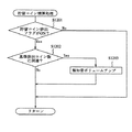
次いで、ステップS904に進み、本発明の特徴的構成の貯留コイン精算処理が行われる。詳細については後述するが、貯留コインの排出である場合、メイン制御基板50からのコマンドに基づいてサブ制御基板60のMPU61は排出されているコインの枚数が基準排出コイン数に到達したのか否かについて判断する。
Next, the process proceeds to step S904, and a stored coin settlement process having a characteristic configuration of the present invention is performed. Although details will be described later, in the case of discharging stored coins, whether or not the number of coins discharged by the
そして、ステップS905に進み、電圧低下チェック処理によりスロットマシン1の電圧状態のチェックが行われると、ステップS906に進み、10msタイマ処理が行われる。10msタイマ処理では、例えば上部ランプ21のLEDの上部ランプ発光用テーブルを更新したり、上述のデバイス制御処理(ステップS902)の例示のように、変更された報知音データがセットされたら、報知音出力コントローラ22aによりスピーカ22の音量を実際に変更したりする処理が行われる。ここでは、10ms毎にタイマ処理を行うようにしているが、より長い周期毎に処理を行っても実際に行われるコイン排出報知制御に影響を与えないことから、例えば100ms程度のタイマ処理として行うようにしても良い。
Then, the process proceeds to step S905, and if the voltage state of the
ステップS906の10msタイマ処理が終了すると、ステップS907に進み、演出データ変更処理が行われる。ここでは、次回の1msタイマ処理において、スピーカ22の報知音を変更し、例えば、スピーカ22からの報知音を一段階大きくするような場合、当該報知音データに基づいて出力される報知音より一段階大きい報知音に関する報知音データをROM63の報知音テーブルから取り出して次回の1msタイマ処理で報知音出力コントローラ22aにセットできるように準備する。
When the 10 ms timer process in step S906 ends, the process proceeds to step S907, and an effect data change process is performed. Here, in the next 1 ms timer process, when the notification sound of the
このようにしてステップS901〜ステップS907までの一連の処理が行われると、本ルーチンは終了する。 When the series of processing from step S901 to step S907 is performed in this way, this routine ends.
図13のメイン処理の説明に戻り、ステップS805の1msタイマ処理が終了すると、ステップS806に進み、システム状態が電圧低下状態であるかどうかの判定がなされる。システム状態が電圧低下状態である場合(ステップS806においてYes)、ステップS802においてシステム状態が電圧低下状態であると判定したときと同様に停電処理に移行する。 Returning to the description of the main process in FIG. 13, when the 1 ms timer process in step S805 ends, the process proceeds to step S806, where it is determined whether or not the system state is a voltage drop state. When the system state is a voltage drop state (Yes in step S806), the process proceeds to a power failure process as in the case where it is determined in step S802 that the system state is a voltage drop state.
一方、割込タイマカウンタにカウント数が加算されていない場合(ステップS803においてNo)及びシステム状態が電圧低下状態でない場合(ステップS806においてNo)、ステップS807に進んで、受信コマンドの有無を判定する。受信コマンドがない場合(ステップS807においてNo)、ステップS809に進んで乱数ベース値を加算することによって更新して、ステップS802に戻る。 On the other hand, when the count number is not added to the interrupt timer counter (No in step S803) and when the system state is not a voltage drop state (No in step S806), the process proceeds to step S807 to determine whether there is a received command. . If there is no reception command (No in step S807), the process proceeds to step S809, where it is updated by adding the random number base value, and the process returns to step S802.
一方、受信コマンドがある場合(ステップS807においてYes)、ステップS808に進み、受信コマンドチェック処理が行われ、メイン制御基板50から送信されてきたコマンドの解析が行われる。
On the other hand, if there is a received command (Yes in step S807), the process proceeds to step S808, where the received command check process is performed, and the command transmitted from the
本ルーチンの受信コマンドチェック処理によるコマンドの解析では、最初に受信コマンド別の処理が行われ、受信したコマンドの種別を認識する。上述のように、メイン制御基板50から送信されてきたコマンドは、サブ制御基板60のMPU61によるコマンド割込処理によってRAM64の所定のワークエリアに格納されていることから(図11参照乞う)、RAM64のワークエリアからコマンドの先頭の1バイト目を読み出し、コマンドの種別を認識する。本実施の形態において、例えば、どのようなコマンドに基づいてホッパ14からコインを支払うのかをサブ制御基板60のMPU61に認識させる払い出し種別情報が設定されている(図15参照乞う)。
In command analysis by the received command check processing of this routine, processing for each received command is first performed to recognize the type of the received command. As described above, the command transmitted from the
次に、コマンドの2バイト目を読み出し、払い出し種別情報に更にコマンドが設定されているのかを認識する。本実施の形態において、例えば、払い出し種別コマンドとして、貯留コイン排出コマンド、投入コイン排出コマンド、獲得コイン払い出しコマンド及び自動精算コマンドの4種類が設定されているので、この中のどのコマンドが送信されてきたのかを解析する。本実施の形態では、例えば、MPU61は貯留コイン排出コマンド(クレジット精算ボタン35の操作によりメイン制御基板50から送信されてくるコマンド)である。
Next, the second byte of the command is read, and it is recognized whether or not a command is further set in the payout type information. In the present embodiment, for example, four types of stored coin discharge command, inserted coin discharge command, acquired coin payout command, and automatic settlement command are set as the payout type command, and any of these commands has been transmitted. Analyze it. In the present embodiment, for example, the
ステップS808の受信コマンドチェック処理により、受信したコマンドの解析が終了すると、ステップS809で乱数ベース値の更新が行われて、ステップS802に戻る。 When the received command analysis is completed by the received command check process in step S808, the random number base value is updated in step S809, and the process returns to step S802.
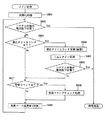
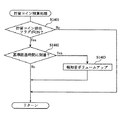
次に、図15〜図17に基づいて本発明の特徴的構成のコイン排出報知制御について説明する。図15は、払い出し種別情報コマンド処理の一例を示すフローチャート、図16は、排出枚数コマンド処理の一例を示すフローチャート、図17は、貯留コイン精算処理の一例を示すフローチャートである。コイン排出報知とは、コインの排出動作が開始されたことを報知する報知演出であり、例えば上部ランプ21から光が発せられたり、スピーカ22から効果音が出力されたりする。コイン排出報知は、通常、スピーカ22から出力される効果音と上部ランプ21から発せられる光に基づいて行われるが、どちらか一方により行われるようにしても良い。
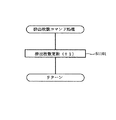
Next, coin discharge notification control having a characteristic configuration of the present invention will be described with reference to FIGS. FIG. 15 is a flowchart showing an example of the payout type information command process, FIG. 16 is a flowchart showing an example of the discharged number command process, and FIG. 17 is a flowchart showing an example of the stored coin settlement process. The coin discharge notification is a notification effect for notifying that the coin discharge operation has started, and for example, light is emitted from the
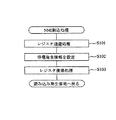
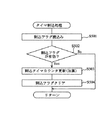
図15に示す払い出し種別情報コマンド処理では、まずステップS1001において貯留コイン排出開始かどうかを判定する。上述したMPU61による受信コマンドチェック処理(ステップS807)で精算排出開始コマンドを受信している場合(Yes)、「貯留コイン排出開始」となる。ステップS1001において、貯留コイン排出開始であると判断された場合(Yes)、ステップS1002に進み、報知制御プログラム63cに基づき通常報知が開始される。
In the payout type information command process shown in FIG. 15, it is first determined in step S1001 whether or not the stored coin discharge is started. When the payment discharge start command is received in the reception command check process (step S807) by the
本実施の形態において、コイン排出報知は、大別して2種類設定されている。一般的に行われる通常報知と、スロットマシン1に対する不正行為によってコインが排出されている可能性が高い旨を報知するコイン異常排出報知である。本実施の形態の場合、コイン異常排出報知については、更に複数のコイン異常排出報知が設定されており、例えば第1コイン異常排出報知と第2コイン異常排出報知が設定されている。第2コイン異常排出報知は、第1コイン異常排出報知より不正行為の行われた可能性が更に高いことを報知するコイン異常排出報知である。
In the present embodiment, the coin discharge notification is roughly classified into two types. A normal notification that is generally performed and a coin abnormal discharge notification that notifies that there is a high possibility that a coin has been discharged due to an illegal act on the
そして、ステップS1002で、1msタイマ処理(図14参照乞う)に基づき報知音がスピーカ22を通じて再生されるように報知音出力コントローラ22aに報知音データを設定し、ステップS1003にて上部ランプ21が点灯されるように発光制御コントローラ21aに上部ランプ発光データを設定する。通常報知の場合、例えば、遊技者、その遊技者の近くで遊技を行っている者等の当該スロットマシン1から近距離にいる者が認識できる程度の音量でスピーカ22から出力されるような一般的な報知音の報知音データを設定する。また、上部ランプ21で通常の点灯又は所定間隔での点滅となるように上部ランプ発光データを発光制御コントローラ21aに設定する。
In step S1002, notification sound data is set in the notification
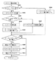
次に、ステップS1004において、受信した精算排出開始コマンドがBB終了後の最初の精算排出開始コマンドであるのかどうかについて判断する。具体的には、MPU61は、ステップS808の受信コマンドチェック処理において受信した特別遊技制御終了コマンドと精算排出開始コマンドに基づいて判定する。すなわち、MPU61は、当該精算排出開始コマンドを受信したときに直前の特別遊技制御終了コマンドとの間に精算排出開始コマンドを受信していないかどうかをチェックする。
Next, in step S1004, it is determined whether or not the received settlement discharge start command is the first settlement discharge start command after the end of the BB. Specifically, the
ステップS1004において、BB終了後の最初の精算排出開始コマンドである場合(Yes)、ステップS1005〜ステップS1007までの処理を行うことなく、貯留コイン排出終了であるかを判定すべくステップS1008にスキップする。一方、BB終了後の最初の精算排出開始コマンドでない場合(No)、ステップS1005にて貯留コイン排出フラグがオンにセットされる。 In step S1004, if it is the first settlement discharge start command after the end of BB (Yes), the process skips to step S1008 to determine whether or not the stored coin discharge has ended without performing the processing from step S1005 to step S1007. . On the other hand, if it is not the first payment start command after the end of BB (No), the stored coin discharge flag is set to ON in step S1005.
そして、貯留コイン排出間ゲーム数判定処理を行うべく、ステップS1006に進み、ステップS1006で前回クレジット精算ボタン35が操作されてから今回クレジット精算ボタン35が操作されるまでに行われた遊技数が予め設定された基準遊技数以下であるかについて判定する。具体的には、MPU61は、遊技数カウントプログラム63aを起動して、コマンド間遊技数(遊技数カウント用コマンドに基づき前回の精算排出開始コマンドを受信したときからステップS1001で精算排出開始コマンドを受信したときまでに行われた遊技数)を算出し、算出した値が予め設定された基準遊技数以下であるのかについて判定する。
Then, in order to perform the game number determination process between the stored coin discharges, the process proceeds to step S1006, and the number of games played from the previous operation of the
ここで、基準遊技数とは、コイン異常排出報知を開始するかどうかの基準となる閾値である。通常、購入したコインを使用して適正に遊技を行う場合、BB等の特別入賞役に入賞しない限り、一般に30ゲーム程度の遊技は行われる。一方、投入コインを不正に認識させる行為によりコインを排出させるような場合には、遊技を行うことが殆どないことから、コマンド間遊技数が少なく、コマンド間遊技数がゼロの場合もある。従って、本実施の形態では、基準遊技数を30ゲームに設定している。 Here, the reference number of games is a threshold value that serves as a reference for determining whether or not to start coin abnormal discharge notification. Normally, when a game is played appropriately using purchased coins, generally, about 30 games are played unless a special winning combination such as BB is won. On the other hand, in the case where coins are discharged by an act of illegally recognizing inserted coins, since there are few games, there are cases where the number of games between commands is small and the number of games between commands is zero. Therefore, in this embodiment, the reference number of games is set to 30 games.
そして、MPU61は、遊技数カウンタ65aのカウント数に基づき算出した値が基準遊技数を超えると判定した場合(ステップS1006においてNo)、貯留コイン排出終了かどうかを判定すべくステップS1008に進む。従って、コマンド間遊技数が基準遊技数を超えている場合には、ステップS1002から通常報知が継続して行われる。
If the
一方、MPU61は、基準遊技数以下であると判定した場合には(ステップS1006においてYes)、本発明の第1コイン異常排出報知を開始すべくステップS1007に進み、例えば報知音の音量が通常報知のときより大音量となるように報知音データを設定する。
On the other hand, if the
具体的には、MPU61は、報知制御プログラム63cを起動させて、1msタイマ処理(図14参照乞う)の中で、ROM63の報知音テーブルから読み出して第1コイン異常排出報知にかかる報知音データを準備し(ステップS907)、次回の1msタイマ処理にて実際に報知音出力コントローラ22aに第1コイン異常排出報知かかる報知音データをセットし(ステップS902)、セットした報知音データに基づいて実際にスピーカ22から報知音を出力する(ステップS906)ように制御する。
Specifically, the
第1コイン異常排出報知では、通常報知に基づきスピーカ22から出力されていた音量より大音量で報知音が出力されるように設定され、例えば遊技場の所定位置に配置された係員までが認識可能な程度の音量にてスピーカ22から報知音を出力するように報知音出力コントローラ22aに報知音データを設定する。また、報知音の音量が漸次大きくなるように報知音出力コントローラ22aに報知音データを設定して第1コイン異常排出報知を行うようにしても良い。
In the first coin abnormal discharge notification, the notification sound is set to be output at a louder volume than the volume output from the
また、第1コイン異常排出報知を開始するときには、単に報知音の音量を大きくするだけでなく、報知音の種類を変えてスピーカ22から出力するように報知音データを報知音出力コントローラ22aに設定しても良い。例えば、サイレン音等の緊急を報知するような報知音によって第1コイン異常排出報知が行われるようにしても良い。
When starting the first coin abnormal discharge notification, the notification sound data is set in the notification
或いは、コインの排出が開始されると、上部ランプ21のLEDの点灯設定等が行われるので(ステップS1003)、第1コイン異常排出報知に基づくスピーカ22からの報知音の出力に対応して、第1コイン異常排出報知に基づく上部ランプ21のLEDの発光制御を開始するように上部ランプ発光データを設定する。例えば、点灯している上部ランプ21を、第1コイン異常排出報知の開始に伴い短い間隔で点滅させるような上部ランプ発光データを選択して発光制御コントローラ21aに設定して発光制御するようにしても良い。
Alternatively, when the coin discharge is started, the lighting setting of the LED of the
第1コイン異常排出報知に基づく上部ランプ21の発光制御を開始する場合でも、図14の1msタイマ処理において、上部ランプ21の上部ランプ発光データを変更し(ステップS907)、次回の1msタイマ処理において上部ランプ21の発光制御コントローラ21aに変更データをセットし(ステップS902)、変更データに基づいて実際に上部ランプ21のLEDの発光制御を切り替える(ステップS906)。
Even when the light emission control of the
そして、上部ランプ21、スピーカ22等においてコイン排出報知を変化させる他に、コマンド間遊技数が基準遊技数以下であると判定したときに(ステップS1006においてYes)、サブ制御基板60の外部集中端子板68を介してスロットマシン1を管理する遊技場のホールコンピュータに不正報知信号を出力するようにしても良い。遊技場の管理者は、ホールコンピュータを通じて不正行為の行われたスロットマシンを特定することができるので、不正行為の特定のための体制を整えることができる。例えば、遊技場の係員を派遣したり、遊技場に設置されている防犯カメラによる撮影を開始したりする。
Then, in addition to changing the coin discharge notification in the
サブ制御基板60のMPU61は、上述した貯留コイン排出間ゲーム数判定処理(ステップS1006)に加え、排出コイン数カウントプログラム63bを起動し、RAM64の所定エリアに一時的に格納したコイン排出コマンドに基づいて排出コイン数カウンタ65bにより排出コイン数をカウントし、RAM64の排出コイン数記憶エリア64bに格納している。具体的には図16のフローチャートに示すように、MPU61は、ステップS1101においてコイン排出コマンドを受信する毎に排出コイン数カウンタ65bに「+1」を加算して排出コイン数記憶エリア64bに格納し、以後、コイン排出コマンドを受信する毎に順次「+1」ずつ加算していく。
The
そして、サブ制御基板60のMPU61は、図16に示したコイン排出コマンド処理に基づいて図17のフローチャートに示す貯留コイン精算処理(ステップS904)を行っている。
Then, the
まずステップS1201において、貯留コイン排出フラグがオンにセットされているかどうかを判定する(ステップS1005)。これにより、MPU61は、メイン制御基板50側においてコイン数記憶エリア54aに記憶させた枚数のコインをクレジット精算ボタン35の操作に基づき実際に排出動作が行われているものと認識する。従って、貯留コイン排出フラグがオンにセットされていない場合(ステップS1201においてNo)、ステップS1202以降の制御処理は行われない。
First, in step S1201, it is determined whether the stored coin discharge flag is set to ON (step S1005). Thereby, the
一方、貯留コイン排出フラグがオンにセットされている場合(ステップS1201においてYes)、ステップS1202に進み、MPU61は、排出コイン数判定プログラム63bに基づき排出コイン数が所定の閾値に到達したのかを判定する。具体的には、サブ制御基板60のMPU61は、RAM64の排出コイン数記憶エリア64bに格納されているカウント数を読み出して、ROM63に格納されている予め設定された基準排出コイン数との対比を行う。
On the other hand, if the stored coin discharge flag is set to ON (Yes in step S1201), the process proceeds to step S1202, and the
基準排出コイン数とは、第1コイン異常排出報知から第2コイン異常排出報知に変化させるための基準となる閾値であり、4枚以上49枚以下の範囲の中で設定され、例えば、本実施において30枚に設定されている。基準排出コイン数に50枚目を含めないのは、50枚目は電子的に記憶可能な最大値であることから、排出枚数が50枚目に到達したときにはコインの排出が終了しているからである。 The reference number of coins discharged is a threshold value used as a reference for changing from the first coin abnormal discharge notification to the second coin abnormal discharge notification, and is set within a range of 4 to 49 coins. Is set to 30 sheets. The reason why the 50th is not included in the reference number of coins to be ejected is that the 50th is the maximum value that can be electronically stored, so that when the number of ejected coins reaches the 50th, the coin has been ejected. It is.
また、不正行為によりコインを排出させるような場合には、周囲に知られないように効率よくコインを入手しようとして行われるので、1回の不正行為でメイン制御基板50のMPU51に50枚のコインを認識させ、その50枚のコインをクレジット精算ボタン35の操作によって実際に排出させるのが一般的である。従って、基準排出コイン数は、4枚以上49枚以下の比較的広範囲内で設定可能ではあるものの、30〜40枚程度の枚数に設定するのが好ましい。
Further, in the case where coins are discharged due to fraud, since it is attempted to obtain coins efficiently so as not to be known to the surroundings, 50 coins are placed on the MPU 51 of the
なお、サブ制御基板60のMPU61は、受信したコイン排出コマンドのカウント数に基づいて排出コイン数を算出しているが、サブ制御基板60のMPU61側で排出コイン数に関する情報を受けることができればどのような方法でも良い。例えば、クレジット精算ボタン35が操作されたときにメイン制御基板50側ではホッパ14から排出させるコインの枚数を算出するので、メイン制御基板50側で算出した情報をコイン排出コマンドとしてサブ制御基板60のMPU61に送信するようにしても良い。
Note that the
排出コイン数判定プログラム63bに基づいてMPU61により読み出された排出コイン数カウンタ65bのカウント数が基準排出コイン数を超える場合(ステップS1202においてYes)、本発明の第2コイン異常排出報知を開始すべくステップS1203に進み、例えば報知音の音量が、第1コイン異常排出報知のときより更に大音量となる。一方、排出コイン数カウンタ65bのカウント数が基準排出コイン数以下である場合(No)、本ルーチンを終了してステップS1201に戻る。
When the count of the discharged
ステップS1202により、コマンド間遊技数が基準遊技数以下であり且つ排出コイン数カウンタ65bのカウント数が基準排出コイン数を超える場合には、スロットマシン1に対して不正行為が行われた可能性が極めて高いと判定することができる。従って、排出コイン数カウンタ65bのカウント数が基準排出コイン数を超える場合(Yes)、第2コイン異常排出報知を開始することにより、不正行為が行われた可能性が極めて高い旨を報知することができる。
If it is determined in step S1202 that the number of games between commands is equal to or less than the reference number of games and the count number of the discharged
第2コイン異常排出報知を開始する場合には、第1コイン異常排出報知のときと同様に、MPU61は、報知制御プログラム63cに基づき、1msタイマ処理の中で、ROM63の報知音テーブルから読み出して第2コイン異常排出報知にかかる報知音データを準備し、次回の1msタイマ処理にて実際に報知音出力コントローラ22aに第2コイン異常排出報知かかる報知音データをセットし、セットした報知音データに基づいて実際にスピーカ22から更に大音量の報知音を出力するように制御する。また、第2コイン異常排出報知に基づき報知音の音量が漸次大きくなるように報知音出力コントローラ22aに報知音データを設定して第2コイン異常排出報知を行っても良い。
When starting the second coin abnormal discharge notification, the
コインの排出が開始されると、上部ランプ21のLEDの点灯等が行われるので、第2コイン異常排出報知に基づくスピーカ22からの報知音の出力に対応して、第2コイン異常排出報知に基づく上部ランプ21のLEDの発光制御を開始するようにしても良い。例えば、第1コイン異常排出報知に基づき短い間隔で点滅している上部ランプ21を、第2コイン異常排出報知の開始に伴い更に短い間隔で点滅させるような上部ランプ発光データを選択して発光制御コントローラ21aに設定し、発光制御を行うようにしても良い。
When the coin discharge is started, the LED of the
第2コイン異常排出報知に基づく上部ランプ21の発光制御を開始する場合でも、図14の1msタイマ処理において、上部ランプ21の上部ランプ発光データを変更し、次回の1msタイマ処理において上部ランプ21の発光制御コントローラ21aに変更データをセットし、変更データに基づいて実際に上部ランプ21のLEDの発光制御を切り替える。
Even when the light emission control of the
そして、上部ランプ21、スピーカ22等においてコイン排出報知を変化させる他に、排出コイン数が基準排出コイン数を超えたと判定したときに、サブ制御基板60の外部集中端子板68を介してスロットマシン1を管理する遊技場のホールコンピュータに出力する不正報知信号の出力手法を変えても良い。
In addition to changing the coin discharge notification in the
このように、ステップS1203において報知音出力コントローラ22aに設定するデータを変更し、その変更データに基づいて第2コイン異常排出報知が行われると本ルーチンを終了し、ステップS1201に戻る。
In this manner, the data set in the notification
図15の払い出し種別情報コマンド処理の説明に戻り、BB後の最初の精算排出開始コマンドであるか(ステップS1004においてYes)、貯留コイン排出間ゲーム数が基準遊技数を超える場合(ステップS1006においてNo)、ステップS1008に進んで、貯留コイン排出が終了したのかどうかを判定する。上述したMPU61による受信コマンドチェック処理(ステップS807)で精算排出終了コマンドを受信している場合(Yes)、「貯留コイン精算終了」となる。
Returning to the description of the payout type information command processing of FIG. 15, is it the first payment start command after BB (Yes in step S1004), or if the number of games during storage coin discharge exceeds the reference game number (No in step S1006)? ), Proceeding to step S1008, it is determined whether or not the stored coin discharge has ended. When the payment discharge end command is received in the reception command check process (step S807) by the
ステップS1008において、精算排出終了コマンドを受信していない場合(No)、貯留コイン排出の終了ではないので、払出し種別情報コマンド処理を終了する。 If it is determined in step S1008 that the payment discharge end command has not been received (No), the payout type information command processing is ended because the stored coin discharge has not ended.
一方、精算排出終了コマンドを受信した場合(Yes)、貯留コイン排出終了であるので、ステップS1009に進んで、MPU61は報知音の出力を中止させるように報知音出力コントローラ22aに報知音データを設定する。また、ステップS1010に進んで、上部ランプ21のLEDを消灯するように発光制御コントローラ21aに発光データを設定する。そして、ステップS1011に進んで、1msタイマ処理の中でスピーカ22の報知音出力コントローラ22aにセットされている報知音データを通常報知にかかる報知音データに変更し、上部ランプ21を形成するLEDの発光データについても通常報知にかかる発光データに変更する設定をそれぞれ行う。
On the other hand, when the settlement discharge end command has been received (Yes), since the storage coin discharge has ended, the process proceeds to step S1009, and the
なお、ステップS1008において貯留コイン排出終了と判断した場合、直ちにステップS1009〜ステップS1011の制御処理を行わないようにしても良い。 If it is determined in step S1008 that the stored coins have been discharged, the control processing in steps S1009 to S1011 may not be performed immediately.
例えば、排出された枚数が31枚程度の基準排出コイン数に近い枚数であったとき、ステップS1008の後に直ちにステップS1009からステップS1011の各段階に移行すると、第2コイン異常排出報知が短時間しか行われないことも考えられる。このような場合、不正行為が行われた可能性が高い旨を報知する第2コイン異常排出報知が短時間しか行われないので、遊技場の管理者が不正行為を確実に特定できない場合がある。従って、貯留コイン排出終了後、一定時間、例えば本実施の形態において30秒程度に亘ってコイン異常排出報知を継続して行うことができるようにしても良い。 For example, when the number of ejected coins is close to the reference number of coins to be ejected, which is about 31 coins, immediately after step S1008, if the process proceeds from step S1009 to step S1011, the second coin abnormality ejection notification is performed for only a short time. It is also possible that this is not done. In such a case, since the second coin abnormal discharge notification for notifying that there is a high possibility that fraud has been performed is performed only for a short time, the manager of the game hall may not be able to reliably identify the fraud. . Therefore, the coin abnormal discharge notification may be continuously performed for a certain period of time, for example, about 30 seconds in the present embodiment, after the stored coins are discharged.
従って、本発明において、第1コイン異常排出報知又は第2コイン異常排出報知が開始されるときには、ROM63に予め設定されている標準コイン排出報知時間を読み出して、実際にコイン異常排出報知を行うようにするのが好ましい。そして、本発明の標準コイン排出報知時間は、コイン異常排出報知が直ちに終了するのを防ぐ程度の長さに予め設定され、例えば、コインを50枚排出するのに必要な時間を設定したり、又は30秒の一定の時間を設定する。
Therefore, in the present invention, when the first coin abnormal discharge notification or the second coin abnormal discharge notification is started, the standard coin discharge notification time set in advance in the
それから、第1コイン異常排出報知又は第2コイン異常排出報知が開始された後にコイン排出報知強制終了コマンドを受信したときには、第1コイン異常排出報知又は第2コイン異常排出報知を終了することなく継続して行うようにする。これにより、不正行為が行われた可能性がある旨を確実に報知することができる。 Then, when the coin discharge notification forced termination command is received after the first coin abnormal discharge notification or the second coin abnormal discharge notification is started, the first coin abnormal discharge notification or the second coin abnormal discharge notification is continued without ending. And do it. Accordingly, it is possible to reliably notify that there is a possibility that an illegal act has been performed.
そして、ステップS1009からステップS1011の各制御処理の後、ステップS1012に進んで、遊技数カウンタ65aのカウント数に基づき認識した遊技数をクリアして、ステップS1013に進み、貯留コイン排出フラグをオフにセットして本ルーチンを終了する。
Then, after each control process from step S1009 to step S1011, the process proceeds to step S1012 to clear the number of games recognized based on the count number of the
なお、上述したステップS1004の判定は、BB終了後の最初の精算排出開始コマンドを受信したのかどうかに基づいて行われているが、他の手法によって判定するようにしても良い。例えば、MPU61は、ステップS1001で受けたコイン精算排出開始コマンドが特別遊技制御終了コマンドを受信した後の所定遊技数(例えば3ゲーム)以下である場合、ステップS1008までスキップするようにしても良い。例えば、BB終了後に、獲得したコインを直ぐに排出することなく上記の3ゲーム程度の遊技を行うこともある。従って、BB終了後の遊技数が所定の閾値以下である場合には、クレジット精算ボタン35が操作されたときに第1コイン異常排出報知が開始されるのを防止するようにしても良い。
In addition, although the determination of step S1004 mentioned above is performed based on whether the first adjustment discharge start command after completion | finish of BB was received, you may make it determine by another method. For example, the
また、BB終了後の最初のコイン精算排出開始コマンドを受信した場合であっても、BB終了後からの遊技数が所定の遊技数、例えば40ゲームを超えているようなときには、第1コイン異常排出報知を開始するようにしても良い。 Even when the first coin settlement / discharge start command after the end of the BB is received, if the number of games after the end of the BB exceeds a predetermined number of games, for example, 40 games, the first coin abnormality You may make it start discharge alert | report.
以上説明したスロットマシン1によれば、セレクタゴトによりRAM54のコイン数記憶エリア54aに記憶させた枚数のコインをクレジット精算ボタン35の操作に基づいて排出するときに、サブ制御基板60のMPU61は、コマンド間遊技数を遊技数カウンタ65aのカウント数に基づき算出している。サブ制御基板60のMPU61は、コマンド間遊技数が基準遊技数以下であると判定すると上部ランプ21、スピーカ22において第1コイン異常排出報知が開始されるように発光制御コントローラ21a、報知音出力コントローラ22aを制御する。これにより、上部ランプ21、スピーカ22において行われている第1コイン異常排出報知を通じて不正行為が行われ可能性のある旨を報知することができる。
According to the
従って、投入コインを不正に認識させるような不正行為に基づきコインが排出される度に通常報知と異なる第1コイン異常排出報知が開始されて周囲に認識されることになるので、繰り返し行われるような不正行為に対する抑止力となり、不正行為が行われるのを抑制することができる。 Accordingly, every time a coin is discharged based on an illegal act that causes the inserted coin to be illegally recognized, a first coin abnormal discharge notification different from the normal notification is started and recognized in the surroundings. It can be a deterrent against unjust acts, and it can be suppressed from being carried out.
また、サブ制御基板60のMP61は、コマンド間遊技数のカウントに加え、コイン排出コマンドに基づき算出した排出コイン数に基づき第2コイン異常排出報知を開始している。基準遊技数と基準排出コイン数の両方の閾値を満たす場合には、不正行為の行われた蓋然性が極めて高いことから、第2コイン異常排出報知を通じて不正行為が行われた可能性が高い旨を報知することができる。
Further, the
そして、第1コイン異常排出報知又は第2コイン異常排出報知は、スピーカ22から出力される報知音が通常報知に基づき出力されるときと異なる報知音をもって出力されるように行われる。従って、このような報知音を通じて不正行為が特定されることから、例えばセレクタ40に対する不正行為の抑止力効果を更に高めることができる。このとき、スピーカ22から報知を出力することに加えて、上部ランプ21のLEDの発光制御を第1コイン異常排出報知又は第2コイン異常排出報知に基づいて行われるように開始することにより、不正行為を更に容易に特定することができる。
Then, the first coin abnormal discharge notification or the second coin abnormal discharge notification is performed so that the notification sound output from the
それから、第1コイン異常排出報知又は第2コイン異常排出報知の開始に伴って、外部集中端子板68を介してホールコンピュータへ不正報知信号を出力することにより、遊技場の管理者は、セレクタ40に対して不正行為に行われたスロットマシンを特定することができるので、不正行為を早期に認識して、その後の対応を迅速に行うことができる。
Then, in response to the start of the first coin abnormal discharge notification or the second coin abnormal discharge notification, the game hall manager outputs the fraud notification signal to the hall computer via the external
更に、クレジット精算ボタン35の操作によりコイン数記憶エリア54aに記憶させた枚数のコインを排出する場合、メイン制御基板50側では、従来通りにコインの排出に関する制御処理のみを行い、サブ制御基板60側において、メイン制御基板50から送信されてきたコマンドに基づいて通常報知、第1コイン異常排出報知又は第2コイン異常排出報知のうちのどの報知動作を開始するのかについて判定していることから、メイン制御基板50側の負担を増大させることなく本発明の作用を奏することができる。なお、このような判定については、メイン制御基板50側において行うようにしても良い。
Further, when the number of coins stored in the coin
(第2実施の形態)
第2実施の形態を図18〜図21に基づいて説明する。なお、第1実施の形態と同様の構成については、同様の符号を付すことにより詳細を省略し、異なる部分について主に説明する。
(Second Embodiment)
A second embodiment will be described with reference to FIGS. In addition, about the structure similar to 1st Embodiment, a detailed description is abbreviate | omitted by attaching | subjecting the same code | symbol, and a different part is mainly demonstrated.
図18は、第2実施の形態におけるメイン制御基板80の構成を説明するブロック図、図19は、サブ制御基板90の構成を説明するブロック図である。なお、図20及び図21に示されたフローチャートのプログラムは、制御プログラムの一部としてROM93内に記憶されている。
FIG. 18 is a block diagram illustrating the configuration of the
第1実施の形態において、サブ制御基板60のMPU61は、受信したコイン排出コマンドを排出コイン数カウンタ65bによってカウントし、そのカウント数に基づいて第2コイン異常排出報知を開始していた。これに対し、第2実施の形態では、排出コイン数カウンタ65bに代えて、経過時間計測タイマ95を搭載し、第1コイン異常排出報知が開始されてから経過した時間を計測している。そして、サブ制御部90のMPU91は、メイン制御基板80から送信されてくる精算排出開始コマンドを受信して、第1コイン異常排出報知が開始されてから経過した時間を経過時間計測タイマ95により計測し、その経過時間を基準経過時間と対比し、第1コイン異常排出報知を継続して行うのか、第2コイン異常排出報知を開始するのかを判断している。
In the first embodiment, the
なお、本発明の経過時間計測部は、経過時間計測タイマ95をサブ制御基板90のMPU91に搭載することによって構成されているが、このような構成に限定されるものではない。例えば、所定周期毎に行われているタイマ割込処理の中で、MPU91によりタイマ割込処理の回数によって経過時間を計測するようにしても良い。このようにソフトウエア的に経過時間計測部を形成することにより、ハードウエア的に新たな構成要素を追加しなくても、通常行われる処理に基づいて経過時間を計測可能となるので、メイン制御基板90の小型化を図ることができる。
The elapsed time measuring unit of the present invention is configured by mounting the elapsed time measuring timer 95 on the
次に、図20及び図21に基づいてコイン排出報知制御について説明する。図20は、払い出し種別情報コマンド処理の一例を示すフローチャート、図21は、貯留コイン精算処理の一例を示すフローチャートである。なお、図20の払い出し種別情報コマンド処理は、第1実施の形態の払い出し種別情報コマンド処理と同様の処理が行われるので、詳細な説明については省略する。 Next, coin discharge notification control will be described with reference to FIGS. FIG. 20 is a flowchart showing an example of the payout type information command process, and FIG. 21 is a flowchart showing an example of the stored coin settlement process. The payout type information command process of FIG. 20 is the same as the payout type information command process of the first embodiment, and thus detailed description thereof is omitted.
図20の払い出し種別情報コマンド処理により、メイン制御基板80から送信されてきた「貯留コイン排出」コマンド(精算排出開始コマンド)を受信すると、ステップS1301において貯留コインの排出が開始されたのかどうかを判定する。貯留コインの排出と判定された場合(Yes)、ステップS1302及びステップS1303において、報知制御プログラム93bに基づき通常報知を開始するように発光制御コントローラ21a及び報知音出力コントローラ22aにそれぞれデータを設定する。
When the “reserved coin discharge” command (settlement discharge start command) transmitted from the
そして、ステップS1304に進み、第1実施の形態と同様にBB終了後の最初の精算排出開始コマンドであるのがどうかを判定する。BB終了後の最初の精算排出開始コマンドである場合(ステップS1304においてYes)、第1実施の形態と同様にステップS1305〜ステップS1307までの処理を行うことなくステップS1308までスキップする。 Then, the process proceeds to step S1304, and it is determined whether or not it is the first settlement discharge start command after the end of the BB as in the first embodiment. If it is the first payment start command after the end of BB (Yes in step S1304), the process skips to step S1308 without performing the processes from step S1305 to step S1307 as in the first embodiment.
一方、BB終了後の最初の精算排出開始コマンドでない場合(ステップS1304においてNo)、ステップS1305で貯留コイン排出フラグをオンにセットされ、ステップS1306に進んで、貯留コイン排出間ゲーム数判定処理が行われる。具体的には、第1実施の形態と同様に遊技数カウンタ95aによりカウントされたコマンド間遊技数に基づいて判定する。そして、MPU91は、コマンド間遊技数が基準遊技数に到達していないものと判定した場合(ステップS1306においてYes)、第1コイン異常排出報知を開始すべくステップS1307に進み、例えば報知音の音量を通常報知のときより大音量となるように報知音データを設定する。このとき、経過時間計測タイマ95bによって第1コイン異常排出報知が開始されてから経過した時間の計測を開始する。
On the other hand, if it is not the first payment start command after the end of BB (No in step S1304), the stored coin discharge flag is set to ON in step S1305, and the process proceeds to step S1306 to perform the game number determination process between stored coin discharges. Is called. Specifically, the determination is made based on the number of games between commands counted by the number-of-
具体的には、第1実施の形態におけるステップS1007の処理と同様の処理が行われ、例えばスピーカ22からの報知音が大音量にて出力されるように報知音出力コントローラ22aに報知音データが設定される。本実施の形態においても、第1コイン異常排出報知に基づいて出力される報知音の出力時間に従って、スピーカ22から出力される報知音の音量を大きくするのが好ましい。また、報知音の音量を変更するのではなく、報知音の種類を変更するようにしても良い。
Specifically, the processing similar to the processing in step S1007 in the first embodiment is performed, and for example, the notification sound data is transmitted to the notification
それから、第1コイン異常排出報知を周囲に確実に認識させる必要があることから、第1実施の形態と同様に、第1コイン異常排出報知は、精算排出終了コマンドを受信してから基準コイン排出報知時間に亘って行われるようにしても良い。これにより、計測時間が基準計測時間に近い時間として得られた場合であっても、経過時間の計測後すぐに第1コイン異常排出報知は終了することなく継続して行われる。 Then, since it is necessary to reliably recognize the first coin abnormal discharge notification to the surroundings, as in the first embodiment, the first coin abnormal discharge notification is issued after receiving the settlement discharge end command. It may be performed over the notification time. Thereby, even if the measurement time is obtained as a time close to the reference measurement time, the first coin abnormality discharge notification is continuously performed without ending immediately after the elapsed time is measured.
また、第1コイン異常排出報知の開始後は、例えばコイン投入口34からのコインの投入等によりRAM84のコイン数記憶エリア84aでのコイン数の蓄積が開始された場合であっても中断されることなく継続して行われるようにしても良い。これにより、セレクタゴトの発生を周囲に対して確実に報知することができる。
Further, after the start of the first coin abnormal discharge notification, for example, when coin accumulation in the coin
そして、第1実施の形態と同様に報知音を変化させるだけでなく、上部ランプ21の発光制御を変化させたり、外部集中端子板98を介して遊技場のホールコンピュータに不正報知信号を出力するようにしても良い。
Then, as in the first embodiment, not only the notification sound is changed, but also the light emission control of the
また、サブ制御基板90のMPU91は、貯留コイン排出間ゲームの判定処理に加え、図21のフローチャートに示した貯留コイン精算処理を行っている。まず、ステップS1401において、貯留コイン排出フラグがオンにセットされているかどうかを判定する。貯留コイン排出フラグがオンにセットされていない場合(ステップS1401においてNo)、本ルーチンは行われることなく終了する。
Further, the
一方、貯留コイン排出フラグがオンにセットされている場合(ステップS1401においてYes)、ステップS1402に進み、第1コイン異常排出報知が開始されてから経過した経過時間が所定の経過時間に到達したのかどうかの判定が行われる。具体的には、サブ制御基板90のMPU91は、RAM94の経過時間記憶エリア94aに格納された計測値(経過時間)を読み出して、ROM93に予め格納されている基準経過時間との対比を行う。
On the other hand, if the stored coin discharge flag is set on (Yes in step S1401), the process proceeds to step S1402 and whether the elapsed time after the start of the first coin abnormal discharge notification has reached a predetermined elapsed time. A determination of whether or not is made. Specifically, the
ここで、基準経過時間とは、第1コイン異常排出報知が開始されたときに経過した経過時間に基づき第1コイン異常排出報知から第2コイン異常排出報知に変化させるかどうかの基準となる閾値であり、4枚以上49枚以下の中で所定枚数のコインが排出されるのに要する時間に設定され、例えば、本実施の形態において30枚のコインを排出するのに要する経過時間に設定している。 Here, the reference elapsed time is a threshold value that serves as a reference for changing from the first coin abnormal discharge notification to the second coin abnormal discharge notification based on the elapsed time that has elapsed when the first coin abnormal discharge notification is started. It is set to the time required to eject a predetermined number of coins between 4 and 49. For example, in this embodiment, it is set to the elapsed time required to eject 30 coins. ing.
そして、MPU91によって読み出された経過時間が基準経過時間に到達した場合(ステップS1402においてYes)、ステップS1403に進み、報知制御プログラム93bに基づき第2コイン異常排出報知を開始する制御処理が行われる。一方、経過時間が基準経過時間に到達していない場合(No)、本ルーチンを終了し、ステップS1401に戻る。
If the elapsed time read by the
ステップS1402において、コマンド間遊技数が基準遊技数以下であり且つ経過時間計測タイマ95bの経過時間が基準経過時間に到達するような場合には、スロットマシン1に対して不正行為が行われた可能性が極めて高いと判定することができる。従って、第1実施の形態と同様に第2コイン異常排出報知を開始することにより、不正行為が行われた可能性が極めて高い旨を報知することができる。
In step S1402, when the number of games between commands is equal to or less than the reference number of games and the elapsed time of the elapsed time measuring timer 95b reaches the reference elapsed time, an illegal act may have been performed on the
図20の払い出し種別情報コマンド処理の説明に戻り、ステップS1306の貯留コイン排出間ゲーム数判定処理が終了するか、又は貯留コイン排出の開始ではない場合(ステップS1301においてNo)、ステップS1308に進んで、貯留コイン排出が終了したのかどうかを判定する。貯留コインの排出の終了か否かは、第1実施の形態と同様に精算排出終了コマンドをサブ制御基板90側において受信したのかどうかに基づき判断される。貯留コイン排出の終了ではないと判断した場合(ステップS1308においてNo)、払出し種別情報コマンド処理を終了する。
Returning to the explanation of the payout type information command process of FIG. 20, when the game number determination process between stored coin discharges in step S1306 is completed or the start of stored coin discharge is not started (No in step S1301), the process proceeds to step S1308. Then, it is determined whether or not the stored coin discharge has ended. Whether or not the storage coins have been discharged is determined based on whether or not the settlement discharge end command has been received on the
一方、貯留コイン排出が終了したと判断した場合(ステップS1308においてYes)、ステップS1309に進んで、MPU91は第2コイン異常排出報知に基づく報知音の出力を停止させるような報知音データを報知音出力コントローラ22aに設定する。また、ステップS1310に進んで、上部ランプ21のLEDを消灯するような発光データを発光制御コントローラ21aに設定する。そして、ステップS1311に進み、1msタイマ処理の中でスピーカ22の報知音出力コントローラ22aにセットされている報知音データを通常報知にかかる報知音データに変更し、上部ランプ21を形成するLEDの発光データについても通常報知にかかる発光データに変更する設定をそれぞれ行う。
On the other hand, if it is determined that the stored coin discharge has ended (Yes in step S1308), the process proceeds to step S1309, and the
そして、ステップS1309からステップS1311の後、ステップS1312に進んで、遊技数カウンタ95aのカウント数をクリアし、ステップS1313に進み、貯留コイン排出フラグをオフにセットして本ルーチンを終了する。
Then, after step S1309 to step S1311, the process proceeds to step S1312, the count number of the
以上説明した第2実施の形態のスロットマシン1によると、第2コイン異常排出報知を開始するかどうかの判定は、第1コイン異常排出報知を開始してから経過した時間をサブ制御基板90側で計測し、経過時間を基準経過時間と対比することにより行われている。
According to the
コイン排出報知の報知時間は、排出される枚数に対応していることから、排出枚数が多い程、実際に行われるコイン排出報知の報知時間も長くなる。例えば、投入コインを不正に認識させる行為によってコインを排出させる場合、一度に多数のコインを排出させようとするので、これに対応して報知時間も長くなるのが一般的である。 Since the notification time of the coin discharge notification corresponds to the number of discharged coins, the notification time of actually performed coin discharge notification becomes longer as the number of discharged coins increases. For example, when coins are discharged by an act of illegally recognizing inserted coins, a large number of coins are discharged at a time, so that the notification time is generally increased accordingly.
従って、MPU91は、第1コイン異常排出報知が開始されてから経過した時間を経過時間計測タイマ95bで計測し、経過時間が基準経過時間に到達するようなときには第2コイン異常排出報知を開始することにより、不正行為の発生の蓋然性が極めて高い旨を報知することができる。
Accordingly, the
また、メイン制御基板80側ではコインの排出開始にかかる精算排出開始コマンドとコインの排出終了にかかる精算排出終了コマンドだけを送信することから、メイン制御基板80の負担の軽減を図ることができる。更に、サブ制御基板90側においては、メイン制御基板80から送信されてきたコマンドを受信してから経過した時間だけを測定するだけでよいことから、簡単な制御処理で第2コイン異常排出報知の開始判断を行うことができる。
Further, since the
1 スロットマシン(遊技機)
2 筐体
3 前面扉
4 本体
11 回転ドラム
13 電源ボックス
14 ホッパ
14c コイン検出センサ(コイン検出部)
21 上部ランプ
21a 発光制御コントローラ
22 スピーカ
22a 報知音出力コントローラ22a
35 クレジット精算ボタン(精算排出開始手段)
40 セレクタ
45 投入コイン通過検出部
45a 第1投入コイン通過検出センサ
45b 第2投入コイン通過検出センサ
50、80 メイン制御基板
51、81 MPU
52、82 入出力ポート
53、83 ROM
54、84 RAM
60、90 サブ制御基板
65a、95a 遊技数カウンタ(遊技数カウント部)
65b 排出コイン数カウンタ
70、100 電源基板
95b 経過時間計測タイマ(経過時間計測部)
1 slot machine (game machine)
2
21
35 Credit checkout button (Settlement discharge start means)
40
52, 82 I /
54, 84 RAM
60, 90
65b Ejected
Claims (12)
前記メイン制御部は、コインの排出を指示する精算排出開始手段の操作に基づきコインの精算排出開始コマンドを前記サブ制御部に送信し、
前記サブ制御部は、前記精算排出開始コマンドに基づいてコインの排出動作が開始されたことを報知するコイン排出報知部に制御信号を送出する遊技機において、
前記サブ制御部は、
前記メイン制御部から送信されてくる遊技数カウント用コマンドに基づき前の精算排出開始コマンドから次の精算排出開始コマンドの間の遊技数であるコマンド間遊技数をカウントする遊技数カウント部を有し、
前記コマンド間遊技数が予め設定された基準遊技数以下のときにはコイン異常排出報知を開始し、前記コマンド間遊技数が前記基準遊技数を超えるときには通常報知を開始することを特徴とする遊技機。 A main control unit that performs main game control processing, and a sub-control unit that is provided separately from the main control unit and performs control processing other than the main game control processing based on a command transmitted from the main control unit, Prepared,
The main control unit transmits a coin settlement payment start command to the sub-control unit based on an operation of a settlement ejection start unit that instructs coin ejection.
The sub-control unit is a gaming machine that sends a control signal to a coin discharge notification unit that notifies that a coin discharge operation has started based on the payment start command.
The sub-control unit
A game number counting unit that counts the number of games between commands, which is the number of games between the previous settlement discharge start command and the next settlement discharge start command, based on the game count counting command transmitted from the main control unit. ,
A gaming machine characterized in that a coin abnormal discharge notification is started when the number of games between commands is equal to or less than a preset reference number of games, and a normal notification is started when the number of games between commands exceeds the reference number of games.
コイン排出報知を強制的に終了させるコイン排出報知強制終了コマンドを受信したときに前記コイン異常排出報知が開始されている場合には、前記コイン異常排出報知を強制終了することなく継続して行うことを特徴とする請求項1又は2に記載の遊技機。 The sub-control unit
When the coin abnormal discharge notification is started when the coin discharge notification forced end command for forcibly terminating the coin discharge notification is received, the coin abnormal discharge notification is continuously performed without forcibly ending. The gaming machine according to claim 1 or 2, characterized in that.
前記サブ制御部は、
前記精算排出開始コマンドを受けたときに、メイン制御部から送信されてくるコイン排出コマンドに基づいて排出されているコインの枚数を算出し、該算出枚数が予め設定された基準排出コイン数以下である場合には、第1コイン異常排出報知を開始し、前記算出枚数が前記基準排出コイン数を超える場合には、第2コイン異常排出報知を開始することを特徴とする請求項1〜3のいずれか1項に記載の遊技機。 The coin abnormal discharge notification includes a first coin abnormal discharge notification and a second coin abnormal discharge notification;
The sub-control unit
When the payment start command is received, the number of coins discharged is calculated based on the coin discharge command transmitted from the main control unit, and the calculated number is equal to or less than a preset reference number of discharged coins. The first coin abnormal discharge notification is started in some cases, and the second coin abnormal discharge notification is started when the calculated number exceeds the reference number of discharged coins. The gaming machine according to any one of the above.
前記コイン異常排出報知が開始されてから経過した時間を計測する経過時間計測部を有し、経過時間が予め設定された基準経過時間に到達するまでは第1コイン異常排出報知を行い、前記経過時間が前記基準経過時間を超えた場合に前記第2コイン異常排出報知を開始することを特徴とする請求項1〜3のいずれか1項に記載の遊技機。 The coin abnormal discharge notification includes a first coin abnormal discharge notification and a second coin abnormal discharge notification;
An elapsed time measuring unit for measuring a time elapsed after the coin abnormal discharge notification is started, and performing the first coin abnormal discharge notification until the elapsed time reaches a preset reference elapsed time; The gaming machine according to any one of claims 1 to 3, wherein the second coin abnormal discharge notification is started when time exceeds the reference elapsed time.
前記コイン異常排出報知は、前記報知音出力手段から出力される報知音の出力手法を変化させることを特徴とする請求項1〜5のいずれか1項に記載の遊技機。 The coin discharge notification unit includes notification sound output means for outputting a notification sound based on a command of the sub-control unit,
The gaming machine according to any one of claims 1 to 5, wherein the coin abnormal discharge notification changes a notification sound output method output from the notification sound output means.
前記コイン異常排出報知は、前記照明手段から発せられる光の発光手法を変化させることを特徴とする請求項1〜5のいずれか1項に記載の遊技機。 The coin discharge notification unit has illumination means for emitting light based on a command of the sub-control unit,
The gaming machine according to claim 1, wherein the coin abnormal discharge notification changes a light emission method of light emitted from the illumination unit.
コインの払出枚数が一般役より多く設定された特別役の遊技が終了した旨の特別遊技制御終了コマンドを受信した後の最初の前記精算排出開始コマンドを受信したときには前記通常報知を行うようにしたことを特徴とする請求項1〜10のいずれか1項に記載の遊技機。 The sub-control unit
The normal notification is made when the first payment start command is received after receiving the special game control end command indicating that the game of the special role in which the number of coins to be paid out is set to be greater than that of the general role is received. The gaming machine according to any one of claims 1 to 10, wherein:
Priority Applications (1)
| Application Number | Priority Date | Filing Date | Title |
|---|---|---|---|
| JP2006115398A JP4899606B2 (en) | 2006-04-19 | 2006-04-19 | Game machine |
Applications Claiming Priority (1)
| Application Number | Priority Date | Filing Date | Title |
|---|---|---|---|
| JP2006115398A JP4899606B2 (en) | 2006-04-19 | 2006-04-19 | Game machine |
Publications (3)
| Publication Number | Publication Date |
|---|---|
| JP2007282964A true JP2007282964A (en) | 2007-11-01 |
| JP2007282964A5 JP2007282964A5 (en) | 2009-05-28 |
| JP4899606B2 JP4899606B2 (en) | 2012-03-21 |
Family
ID=38755261
Family Applications (1)
| Application Number | Title | Priority Date | Filing Date |
|---|---|---|---|
| JP2006115398A Expired - Fee Related JP4899606B2 (en) | 2006-04-19 | 2006-04-19 | Game machine |
Country Status (1)
| Country | Link |
|---|---|
| JP (1) | JP4899606B2 (en) |
Cited By (5)
| Publication number | Priority date | Publication date | Assignee | Title |
|---|---|---|---|---|
| JP2009247387A (en) * | 2008-04-01 | 2009-10-29 | Sankyo Co Ltd | Slot machine |
| JP2014033916A (en) * | 2012-08-10 | 2014-02-24 | Daikoku Denki Co Ltd | Token counter |
| JP2014221359A (en) * | 2014-06-24 | 2014-11-27 | 株式会社三共 | Slot machine |
| JP2020189145A (en) * | 2020-08-11 | 2020-11-26 | 株式会社ユニバーサルエンターテインメント | Game machine |
| JP2020189146A (en) * | 2020-08-11 | 2020-11-26 | 株式会社ユニバーサルエンターテインメント | Game machine |
Citations (9)
| Publication number | Priority date | Publication date | Assignee | Title |
|---|---|---|---|---|
| JPH0362364U (en) * | 1989-10-20 | 1991-06-18 | ||
| JPH11164937A (en) * | 1997-12-05 | 1999-06-22 | Mamiya Op Co Ltd | Medal supply device and slot machine system |
| JP2001029543A (en) * | 1999-07-21 | 2001-02-06 | Takasago Electric Ind Co Ltd | Fraudulence alarm device of game machine |
| JP2001120714A (en) * | 1999-10-22 | 2001-05-08 | Konami Co Ltd | Game machine and controlling method |
| JP2002177444A (en) * | 2000-12-11 | 2002-06-25 | Kita Denshi Corp | Slot machine |
| JP2005287882A (en) * | 2004-04-01 | 2005-10-20 | Olympia:Kk | Game machine |
| JP2005323705A (en) * | 2004-05-13 | 2005-11-24 | Olympia:Kk | Game machine, program for game machine, and computer readable recording medium having program for game machine recorded thereon |
| JP2007130140A (en) * | 2005-11-09 | 2007-05-31 | Abilit Corp | Fraudulence detection method for game apparatus, game apparatus used for the method, and game parlor system |
| JP2007195938A (en) * | 2005-12-28 | 2007-08-09 | Sanyo Product Co Ltd | Game machine |
-
2006
- 2006-04-19 JP JP2006115398A patent/JP4899606B2/en not_active Expired - Fee Related
Patent Citations (9)
| Publication number | Priority date | Publication date | Assignee | Title |
|---|---|---|---|---|
| JPH0362364U (en) * | 1989-10-20 | 1991-06-18 | ||
| JPH11164937A (en) * | 1997-12-05 | 1999-06-22 | Mamiya Op Co Ltd | Medal supply device and slot machine system |
| JP2001029543A (en) * | 1999-07-21 | 2001-02-06 | Takasago Electric Ind Co Ltd | Fraudulence alarm device of game machine |
| JP2001120714A (en) * | 1999-10-22 | 2001-05-08 | Konami Co Ltd | Game machine and controlling method |
| JP2002177444A (en) * | 2000-12-11 | 2002-06-25 | Kita Denshi Corp | Slot machine |
| JP2005287882A (en) * | 2004-04-01 | 2005-10-20 | Olympia:Kk | Game machine |
| JP2005323705A (en) * | 2004-05-13 | 2005-11-24 | Olympia:Kk | Game machine, program for game machine, and computer readable recording medium having program for game machine recorded thereon |
| JP2007130140A (en) * | 2005-11-09 | 2007-05-31 | Abilit Corp | Fraudulence detection method for game apparatus, game apparatus used for the method, and game parlor system |
| JP2007195938A (en) * | 2005-12-28 | 2007-08-09 | Sanyo Product Co Ltd | Game machine |
Cited By (7)
| Publication number | Priority date | Publication date | Assignee | Title |
|---|---|---|---|---|
| JP2009247387A (en) * | 2008-04-01 | 2009-10-29 | Sankyo Co Ltd | Slot machine |
| JP2014033916A (en) * | 2012-08-10 | 2014-02-24 | Daikoku Denki Co Ltd | Token counter |
| JP2014221359A (en) * | 2014-06-24 | 2014-11-27 | 株式会社三共 | Slot machine |
| JP2020189145A (en) * | 2020-08-11 | 2020-11-26 | 株式会社ユニバーサルエンターテインメント | Game machine |
| JP2020189146A (en) * | 2020-08-11 | 2020-11-26 | 株式会社ユニバーサルエンターテインメント | Game machine |
| JP7132985B2 (en) | 2020-08-11 | 2022-09-07 | 株式会社ユニバーサルエンターテインメント | game machine |
| JP7132984B2 (en) | 2020-08-11 | 2022-09-07 | 株式会社ユニバーサルエンターテインメント | game machine |
Also Published As
| Publication number | Publication date |
|---|---|
| JP4899606B2 (en) | 2012-03-21 |
Similar Documents
| Publication | Publication Date | Title |
|---|---|---|
| JP5176247B2 (en) | Amusement stand | |
| JP5835855B1 (en) | Game machine | |
| JP6159311B2 (en) | Amusement stand | |
| JP5835854B1 (en) | Game machine | |
| JP5217864B2 (en) | Game machine | |
| JP6669227B2 (en) | Gaming machine | |
| JP4919010B2 (en) | Game machine | |
| JP2024157957A (en) | Gaming Machines | |
| JP4899606B2 (en) | Game machine | |
| JP2006288448A (en) | Game machine | |
| JP5423249B2 (en) | Game machine | |
| JP5874766B2 (en) | Game machine | |
| JP6090367B2 (en) | Game machine | |
| JP5874714B2 (en) | Game machine | |
| JP6565142B2 (en) | Game machine | |
| JP6565144B2 (en) | Game machine | |
| JP5487807B2 (en) | Game machine | |
| JP2016019694A (en) | Game machine | |
| JP2005312499A (en) | Game machine | |
| JP2024157907A (en) | Gaming Machines | |
| JP6168177B2 (en) | Game machine | |
| JP5609948B2 (en) | Game machine | |
| JP2006255176A (en) | Game machine | |
| JP2008278990A (en) | Game machine | |
| JP2019205854A (en) | Game machine |
Legal Events
| Date | Code | Title | Description |
|---|---|---|---|
| A521 | Request for written amendment filed |
Free format text: JAPANESE INTERMEDIATE CODE: A523 Effective date: 20090410 |
|
| A621 | Written request for application examination |
Free format text: JAPANESE INTERMEDIATE CODE: A621 Effective date: 20090410 |
|
| A131 | Notification of reasons for refusal |
Free format text: JAPANESE INTERMEDIATE CODE: A131 Effective date: 20110920 |
|
| A521 | Request for written amendment filed |
Free format text: JAPANESE INTERMEDIATE CODE: A523 Effective date: 20111116 |
|
| TRDD | Decision of grant or rejection written | ||
| A01 | Written decision to grant a patent or to grant a registration (utility model) |
Free format text: JAPANESE INTERMEDIATE CODE: A01 Effective date: 20111206 |
|
| A01 | Written decision to grant a patent or to grant a registration (utility model) |
Free format text: JAPANESE INTERMEDIATE CODE: A01 |
|
| A61 | First payment of annual fees (during grant procedure) |
Free format text: JAPANESE INTERMEDIATE CODE: A61 Effective date: 20111219 |
|
| R150 | Certificate of patent or registration of utility model |
Ref document number: 4899606 Country of ref document: JP Free format text: JAPANESE INTERMEDIATE CODE: R150 Free format text: JAPANESE INTERMEDIATE CODE: R150 |
|
| FPAY | Renewal fee payment (event date is renewal date of database) |
Free format text: PAYMENT UNTIL: 20150113 Year of fee payment: 3 |
|
| R250 | Receipt of annual fees |
Free format text: JAPANESE INTERMEDIATE CODE: R250 |
|
| R250 | Receipt of annual fees |
Free format text: JAPANESE INTERMEDIATE CODE: R250 |
|
| R250 | Receipt of annual fees |
Free format text: JAPANESE INTERMEDIATE CODE: R250 |
|
| R250 | Receipt of annual fees |
Free format text: JAPANESE INTERMEDIATE CODE: R250 |
|
| R250 | Receipt of annual fees |
Free format text: JAPANESE INTERMEDIATE CODE: R250 |
|
| R250 | Receipt of annual fees |
Free format text: JAPANESE INTERMEDIATE CODE: R250 |
|
| R250 | Receipt of annual fees |
Free format text: JAPANESE INTERMEDIATE CODE: R250 |
|
| R250 | Receipt of annual fees |
Free format text: JAPANESE INTERMEDIATE CODE: R250 |
|
| R250 | Receipt of annual fees |
Free format text: JAPANESE INTERMEDIATE CODE: R250 |
|
| LAPS | Cancellation because of no payment of annual fees |