JP2007282913A - Wheelchair hub - Google Patents
Wheelchair hub Download PDFInfo
- Publication number
- JP2007282913A JP2007282913A JP2006114750A JP2006114750A JP2007282913A JP 2007282913 A JP2007282913 A JP 2007282913A JP 2006114750 A JP2006114750 A JP 2006114750A JP 2006114750 A JP2006114750 A JP 2006114750A JP 2007282913 A JP2007282913 A JP 2007282913A
- Authority
- JP
- Japan
- Prior art keywords
- brake
- hub
- peripheral surface
- brake drum
- inner peripheral
- Prior art date
- Legal status (The legal status is an assumption and is not a legal conclusion. Google has not performed a legal analysis and makes no representation as to the accuracy of the status listed.)
- Pending
Links
- 230000002093 peripheral effect Effects 0.000 claims abstract description 69
- 238000013016 damping Methods 0.000 claims abstract description 35
- 230000006835 compression Effects 0.000 claims description 31
- 238000007906 compression Methods 0.000 claims description 31
- 238000013459 approach Methods 0.000 claims description 5
- 230000001932 seasonal effect Effects 0.000 abstract description 3
- 230000002441 reversible effect Effects 0.000 description 25
- 230000002265 prevention Effects 0.000 description 20
- 238000003780 insertion Methods 0.000 description 6
- 230000037431 insertion Effects 0.000 description 6
- 230000008878 coupling Effects 0.000 description 5
- 238000010168 coupling process Methods 0.000 description 5
- 238000005859 coupling reaction Methods 0.000 description 5
- 230000036544 posture Effects 0.000 description 4
- 230000033001 locomotion Effects 0.000 description 3
- 230000002238 attenuated effect Effects 0.000 description 2
- 238000005452 bending Methods 0.000 description 1
- 230000005540 biological transmission Effects 0.000 description 1
- 230000007423 decrease Effects 0.000 description 1
- 230000003247 decreasing effect Effects 0.000 description 1
- 230000000694 effects Effects 0.000 description 1
- 230000000149 penetrating effect Effects 0.000 description 1
- 238000000926 separation method Methods 0.000 description 1
Images

Landscapes
- Braking Arrangements (AREA)
Abstract
【課題】ハブ軸(22)に同軸状に外嵌されたハブ体(2)と、前記ハブ軸(22)と前記ハブ体(2)との相対回転に抵抗を与える回転力減衰装置(54)を備えた、車椅子用ハブに於いて、季節の移り変わり等に基づく外気温変化にかかわらず、回転力減衰装置(54)の定性能が確保できるようにすると共に、該回転力減衰装置(54)の性能調節を可能にする。
【解決手段】ブレーキドラム(3)が前記ハブ体(2)の一方端に同軸状に固定されており、前記回転力減衰装置(54)は、前記ブレーキドラム(3)の内周面に対して摩擦接触状態と非接触状態に変化し、且つ前記ハブ軸(22)に対して回り止め状態にある摩擦抵抗付与手段と、前記摩擦抵抗付与手段を前記ブレーキドラム(3)に対して前記摩擦接触状態に押し付ける力を調節する抵抗調節手段と、を具備し、前記摩擦抵抗付与手段は、操作部の操作に連動して前記摩擦接触状態と非接触状態に切替えられる。
【選択図】図2A hub body (2) coaxially fitted on a hub shaft (22), and a rotational force damping device (54) for imparting resistance to relative rotation between the hub shaft (22) and the hub body (2). ), It is possible to ensure the constant performance of the rotational force attenuating device (54) regardless of the outside air temperature change due to seasonal changes, etc., and the rotational force attenuating device (54 ) Performance adjustment.
A brake drum (3) is coaxially fixed to one end of the hub body (2), and the rotational force damping device (54) is connected to an inner peripheral surface of the brake drum (3). The frictional resistance applying means that changes between the frictional contact state and the non-contacting state and is in a non-rotating state with respect to the hub shaft (22); and the frictional resistance applying means with respect to the brake drum (3) Resistance adjusting means for adjusting the force pressed against the contact state, and the frictional resistance applying means is switched between the friction contact state and the non-contact state in conjunction with the operation of the operation unit.
[Selection] Figure 2
Description
本発明は、車椅子用ハブ、特に、下り坂での暴走を防止する為に車輪の回転に抵抗を付与する回転力減衰装置を備えた車椅子用ハブに関するものである。 The present invention relates to a wheelchair hub, and more particularly to a wheelchair hub provided with a rotational force damping device that imparts resistance to wheel rotation to prevent runaway on a downhill.
出願人は、この種の車椅子用ハブとして図10に示す構造のものを既に出願した(特許文献3,4)。
車椅子の車体フレーム(F)にナット(99)(99)で固定されるハブ(H)は、ハブ軸(22)と、これに対してベアリング(23)で回転自在に支持されるハブ体(2)を備えていると共に、ハブ体(2)の外端に形成されたハブフランジ(28)の外周近傍とリム(図示せず)の間には、スポーク(S)が張設されている。
前記ハブフランジ(28)には、下り坂での車椅子の暴走を防止する為、車輪の回転に抵抗を与える回転力減衰装置(54)が設けられている。
The applicant has already applied for a wheelchair hub of this type having the structure shown in FIG. 10 (Patent Documents 3 and 4).
The hub (H) fixed to the body frame (F) of the wheelchair with the nuts (99) (99) is a hub body (22) and a hub body rotatably supported by a bearing (23) with respect to the hub shaft (22). 2) and a spoke (S) is stretched between the outer periphery of the hub flange (28) formed at the outer end of the hub body (2) and the rim (not shown). .
The hub flange (28) is provided with a rotational force damping device (54) that provides resistance to wheel rotation in order to prevent the wheelchair from running downhill.
ハブ軸(22)の先端には第1軸孔(27)が開放していると共に、回転力減衰装置(54)には前記第1軸孔(27)に対向する第2軸孔(56)を備えたアンカーブロック(B)が連設されている。第1,第2軸孔(27)(56)の内周の夫々には、スプライン溝(270)(560)が形成されていると共に、該スプライン溝(270)(560)には、スプライン軸(57)の外周のスプライン溝(570)が摺動自在に噛み合っている。又、スプライン軸(57)は、バネ(58)で突出方向に付勢されていると共に、バネ(58)を圧縮する方向にワイヤ(W)で引っ張られるように構成されている。 A first shaft hole (27) is opened at the tip of the hub shaft (22), and a second shaft hole (56) facing the first shaft hole (27) is provided in the rotational force damping device (54). The anchor block (B) provided with is continuously provided. Spline grooves (270) and (560) are formed in the inner circumferences of the first and second shaft holes (27) and (56), and the spline grooves (270) and (560) have spline shafts. The spline groove (570) on the outer periphery of (57) is slidably engaged. The spline shaft (57) is urged in a protruding direction by a spring (58) and is pulled by a wire (W) in a direction to compress the spring (58).
回転力減衰装置(54)は、公知のロータリダンパーであり、例えば、オイルダンパが採用される。
このものでは、平坦面での走行時には、スプライン軸(57)をバネ(58)の付勢力に抗してワイヤ(W)で引っ張り、これにより、スプライン軸(57)をアンカーブロック(B)の第2軸孔(56)から脱出させる。すると、ハブ軸(22)と回転力減衰装置(54)の連結が解除され、ハブ体(2)とハブ軸(22)の相対回転に対する抵抗が消失する。これにより、平坦面での円滑走行が確保できる。
The rotational force damping device (54) is a known rotary damper, for example, an oil damper.
In this case, when traveling on a flat surface, the spline shaft (57) is pulled by the wire (W) against the urging force of the spring (58), whereby the spline shaft (57) is pulled by the anchor block (B). Escape from the second shaft hole (56). Then, the connection between the hub shaft (22) and the rotational force attenuating device (54) is released, and resistance to relative rotation between the hub body (2) and the hub shaft (22) disappears. Thereby, smooth running on a flat surface can be secured.
一方、下り坂での車椅子の暴走を防止するときは、図10に示すように、スプライン軸(57)の両端をハブ軸(22)とアンカーブロック(B)の第1,第2軸孔(27)(56)に侵入させた状態に維持する。すると、スプライン軸(57)が、ハブ軸(22)とアンカーブロック(B)の第1,第2軸孔(27)(56)の両者に回り止め状態に噛み合って回転力減衰装置(54)が作動状態になる。即ち、回転力減衰装置(54)とハブ軸(22)がスプライン軸(57)を介して動力伝達状態に連結され、これにより、ハブ軸(22)とハブ体(2)の相対回転に対する抵抗が生じて車輪の回転力が減衰される。これにより、下り坂での暴走が防止される。
しかしながら、上記のように、回転力減衰装置(54)としてオイルダンパを利用すると、例えば、季節の移り変わり等に基づく外気温変化に伴ってオイルの粘度が変化するから、回転力減衰装置(54)の性能が安定性しないという問題があった。
又、オイルダンパを利用する回転力減衰装置(54)では、外気温変化等で性能が変化しても、該性能を調節して適正状態に戻すことができないという問題もあった。
However, as described above, when the oil damper is used as the rotational force attenuating device (54), for example, the viscosity of the oil changes in accordance with a change in the outside air temperature due to a change in season, etc., the rotational force attenuating device (54) There was a problem that the performance of was not stable.
Further, the rotational force damping device (54) using the oil damper has a problem that even if the performance changes due to a change in the outside air temperature, the performance cannot be adjusted and returned to an appropriate state.
本発明は、かかる点に鑑みてなされたもので、
『ハブ軸(22)に同軸状に外嵌されたハブ体(2)と、
前記ハブ軸(22)と前記ハブ体(2)との相対回転に抵抗を与える回転力減衰装置(54)を備えた、車椅子用ハブ』に於いて、季節の移り変わり等に基づく外気温変化にかかわらず、回転力減衰装置(54)の安定性能が確保できるようにする共に、該回転力減衰装置(54)の性能調節を可能にすることを課題とする。
The present invention has been made in view of such points,
`` Hub body (2) coaxially fitted on hub shaft (22),
In the wheelchair hub equipped with a rotational force damping device (54) that gives resistance to relative rotation between the hub shaft (22) and the hub body (2), in response to changes in the outside air temperature due to seasonal changes, etc. Regardless, it is an object to ensure stable performance of the rotational force attenuating device (54) and to enable performance adjustment of the rotational force attenuating device (54).
[請求項1に係る発明]
上記課題を解決する為の請求項1に係る発明の解決手段は、
『ブレーキドラム(3)が前記ハブ体(2)の一方端に同軸状に固定されており、
前記回転力減衰装置(54)は、
前記ブレーキドラム(3)の内周面に対して摩擦接触状態と非接触状態に変化し、且つ前記ハブ軸(22)に対して回り止め状態にある摩擦抵抗付与手段と、
前記摩擦抵抗付与手段を前記ブレーキドラム(3)に対して前記摩擦接触状態に押し付ける力を調節する抵抗調節手段と、を具備し、
前記摩擦抵抗付与手段は、操作部の操作に連動して前記摩擦接触状態と非接触状態に切替えられる』ことである。
上記解決手段は次のように作用する。
下り坂での車椅子の暴走を防止するときは、ハブ体(2)の一方端に同軸状に固定されたブレーキドラム(3)に摩擦抵抗付与手段を摩擦接触させるように、操作部を操作する。すると、摩擦抵抗付与手段は、前記ハブ体(2)と同軸状のハブ軸(22)に回り止め状態にあるから、摩擦抵抗付与手段の前記摩擦接触により、ハブ体(2)とハブ軸(22)の相対回転に抵抗が生じて車輪の回転力が減衰される。即ち、下り坂での車椅子の暴走が防止される。
[Invention of Claim 1]
The solution means of the invention according to
“The brake drum (3) is coaxially fixed to one end of the hub body (2),
The rotational force damping device (54)
Friction resistance applying means that changes between a frictional contact state and a non-contact state with respect to the inner peripheral surface of the brake drum (3), and is in a non-rotating state with respect to the hub shaft (22),
Resistance adjusting means for adjusting a force for pressing the frictional resistance applying means against the brake drum (3) in the frictional contact state, and
The frictional resistance applying means is switched between the frictional contact state and the non-contact state in conjunction with the operation of the operation unit.
The above solution works as follows.
To prevent wheelchair runaway on a downhill, operate the operating section so that the friction resistance applying means is brought into frictional contact with the brake drum (3) coaxially fixed to one end of the hub body (2). . Then, since the frictional resistance applying means is in a non-rotating state on the hub shaft (22) coaxial with the hub body (2), the hub body (2) and the hub shaft ( Resistance to the relative rotation of 22) occurs and the rotational force of the wheel is attenuated. That is, the runaway of the wheelchair on the downhill is prevented.
この場合、上記解決手段によれば、摩擦抵抗付与手段をブレーキドラム(3)に対して摩擦接触状態に押し付ける力を調節する抵抗調節手段が設けられているから、既述オイルダンパ式のものと相違し、前記抵抗を適正な大きさに調節できる。 In this case, according to the above solution means, since the resistance adjusting means for adjusting the force for pressing the friction resistance applying means against the brake drum (3) in a frictional contact state is provided, the oil damper type described above is provided. The resistance can be adjusted to an appropriate size.
一方、操作部の操作により、摩擦抵抗付与手段をブレーキドラム(3)に対して非接触状態に変化させると、ハブ体(2)とハブ軸(22)の相対回転に抵抗が付与されないから、平坦面での車椅子の円滑走行が確保できる。
[請求項2に係る発明]
請求項1に係る発明に於いて、
『前記摩擦抵抗付与手段は、
前記ブレーキドラム(3)の内周面に接触・離反する摩擦ライニング(101)が固定された一対の回動自在な抵抗付与アーム(100)(100)と、
前記一対の抵抗付与アーム(100)(100)の自由端を接近させる方向に付勢する解除バネと、
前記一対の抵抗付与アーム(100)(100)の自由端相互で挟圧された状態で回動することにより前記自由端を相互に離反させて前記摩擦ライニング(101)を前記ブレーキドラム(3)の内周面に接触させる回動カム(91)と、
前記摩擦ライニング(101)を前記ブレーキドラム(3)の内周面に接触させるときとは逆の解除方向に前記回動カム(91)を回動させる解除レバーを具備し、
前記抵抗調節手段は、
前記摩擦ライニング(101)を前記ブレーキドラム(3)の内周面に接触させる方向の回動カム(91)の回動力を増加させる向きに前記解除レバーを押す圧縮バネと、
前記圧縮バネの圧縮量を調節する圧縮量調節ネジを具備し、
前記解除レバーは、前記操作部の操作に連動して前記回動カム(91)を前記解除方向に回動させるように回動する』構成を採用できる。
このものでは、一対の抵抗付与アーム(100)(100)の自由端相互が、これらに挟圧された回動カム(91)の回動によって離反され、これにより、各抵抗付与アーム(100)に固定された摩擦ライニング(101)がブレーキドラム(3)の内周面に押圧されて摩擦接触状態になる。これにより、回転力減衰装置(54)が作動状態になり、下り坂での車椅子の暴走が防止できる。
On the other hand, when the frictional resistance applying means is changed to a non-contact state with respect to the brake drum (3) by operating the operation unit, resistance is not applied to the relative rotation of the hub body (2) and the hub shaft (22). Smooth running of the wheelchair on a flat surface can be ensured.
[Invention of Claim 2]
In the invention according to
"The frictional resistance applying means is
A pair of turnable resistance applying arms (100) (100) to which a friction lining (101) contacting and separating from the inner peripheral surface of the brake drum (3) is fixed;
A release spring that urges the pair of resistance applying arms (100) (100) in a direction to approach the free ends;
The pair of resistance-applying arms (100) (100) are rotated in a state where they are sandwiched between the free ends, so that the free ends are separated from each other, and the friction lining (101) is attached to the brake drum (3). A rotating cam (91) to be brought into contact with the inner peripheral surface of
A release lever that rotates the rotating cam (91) in a release direction opposite to that when the friction lining (101) is brought into contact with the inner peripheral surface of the brake drum (3);
The resistance adjusting means includes
A compression spring that pushes the release lever in a direction to increase the rotational force of the rotating cam (91) in a direction in which the friction lining (101) is brought into contact with the inner peripheral surface of the brake drum (3);
Comprising a compression amount adjusting screw for adjusting the compression amount of the compression spring;
The release lever can be configured to rotate so as to rotate the rotation cam (91) in the release direction in conjunction with the operation of the operation unit.
In this configuration, the free ends of the pair of resistance applying arms (100) and (100) are separated from each other by the rotation of the rotating cam (91) clamped between them, thereby each resistance applying arm (100). The friction lining (101) fixed to the inner surface of the brake drum (3) is pressed against the inner peripheral surface of the brake drum (3) to be in a frictional contact state. As a result, the rotational force attenuating device (54) is activated, and the wheelchair runaway on the downhill can be prevented.
一方、回転力減衰装置(54)を作動させないとき(平坦面での走行時等)には、操作部の操作によって解除レバーを回動させ、該解除レバーにより、回動カム(91)を解除方向に回動させる。即ち、摩擦ライニング(101)をブレーキドラム(3)の内周面に接触させるときとは逆の方向(解除方向)に前記回動カム(91)を回動させる。これにより、摩擦ライニング(101)がブレーキドラム(3)の内周面から離反し、平滑面等での車椅子の円滑走行が確保できる。 On the other hand, when the rotational force damping device (54) is not operated (when running on a flat surface, etc.), the release lever is rotated by operating the operation unit, and the rotary cam (91) is released by the release lever. Rotate in the direction. That is, the rotating cam (91) is rotated in a direction (release direction) opposite to that when the friction lining (101) is brought into contact with the inner peripheral surface of the brake drum (3). Accordingly, the friction lining (101) is separated from the inner peripheral surface of the brake drum (3), and smooth running of the wheelchair on a smooth surface or the like can be ensured.
[請求項3に係る発明]
請求項1又は2に係る発明に於いて、
『回動先端部が前記ブレーキドラム(3)の内周面に接近する方向にバネで付勢された回動自在な制動アーム(6)を前記ブレーキドラム(3)内に配設し、
前記制動アーム(6)の回動先端部には、前記制動アーム(6)の回動に伴なって前記ブレーキドラム(3)の内周面に接触・離反する制動ライニング(60)が連設され、
前記制動ライニング(60)が前記ブレーキドラム(3)の内周面に接触した状態では、前記制動アーム(6)の回動支点と前記回動先端部と前記ブレーキドラム(3)の回転中心が直線状に並ばないように構成し、
外周面が前記ブレーキドラム(3)の内周面に沿った円弧状に形成されているブレーキシュー(67)が、前記制動アーム(6)の前記回動先端部に前記回動方向へ首振り自在に設けられており、
前記ブレーキシュー(67)の外周面に前記制動ライニング(60)が添設されている』構成を採用できる。
このものでは、車椅子の後退時には、後述するように、制動アーム(6)がブレーキドラム(3)の内周面を突っ張るように押圧した状態(以下、「クサビ係合」という。)になる方向に車輪が回転するものとする。
[Invention of Claim 3]
In the invention according to
`` A rotatable braking arm (6) biased by a spring in a direction in which the rotating tip portion approaches the inner peripheral surface of the brake drum (3) is disposed in the brake drum (3),
A braking lining (60) that contacts and separates from the inner peripheral surface of the brake drum (3) as the braking arm (6) rotates is continuously provided at the rotating tip of the braking arm (6). And
When the brake lining (60) is in contact with the inner peripheral surface of the brake drum (3), the rotation fulcrum of the brake arm (6), the rotation tip, and the rotation center of the brake drum (3) are Configure not to line up in a straight line,
A brake shoe (67) having an outer peripheral surface formed in an arc shape along the inner peripheral surface of the brake drum (3) swings in the rotational direction at the rotational tip of the braking arm (6). It is provided freely,
The brake lining (60) is attached to the outer peripheral surface of the brake shoe (67) ”.
In this case, when the wheelchair is moved backward, as will be described later, the braking arm (6) is pressed so as to stretch the inner peripheral surface of the brake drum (3) (hereinafter referred to as “wedge engagement”). It is assumed that the wheel rotates.
上記解決手段によれば、制動アーム(6)の回動先端に添設された制動ライニング(60)が前記ブレーキドラム(3)の内周面に接触した状態では、前記制動アーム(6)の回動支点と前記回動先端部と前記ブレーキドラム(3)の回転中心が直線状に並ばないように構成されている。従って、この状態で車椅子が上り坂で後退すると、制動ライニング(60)がブレーキドラム(3)の内周面との摩擦力で引き摺られて移動する。その結果、前記制動アーム(6)の回動先端部及び回動支点と前記ブレーキドラム(3)の回転中心が一直線上に並ぼうとする。これにより、制動アーム(6)がブレーキドラム(3)の内周面を突っ張るように押圧した状態(以下、「クサビ係合」という。)になり、ブレーキドラム(3)の逆回転が阻止されて車椅子の後退が防止される。 According to the above solution, in a state where the braking lining (60) attached to the rotating tip of the braking arm (6) is in contact with the inner peripheral surface of the brake drum (3), the braking arm (6) The rotation fulcrum, the rotation tip portion, and the rotation center of the brake drum (3) are configured not to be arranged in a straight line. Accordingly, when the wheelchair moves backward on the uphill in this state, the braking lining (60) is dragged and moved by the frictional force with the inner peripheral surface of the brake drum (3). As a result, the rotation tip and rotation fulcrum of the brake arm (6) and the rotation center of the brake drum (3) try to line up in a straight line. As a result, the brake arm (6) is pressed so as to stretch the inner peripheral surface of the brake drum (3) (hereinafter referred to as “wedge engagement”), and reverse rotation of the brake drum (3) is prevented. Wheelchair retreat is prevented.
この場合、請求項3の解決手段では、制動アーム(6)の回動方向へ首振り自在なブレーキシュー(67)が設けられていると共に、該ブレーキシュー(67)の外周面には制動ライニング(60)が添設されている。 In this case, the solution means of claim 3 is provided with a brake shoe (67) swingable in the rotational direction of the brake arm (6), and a brake lining on the outer peripheral surface of the brake shoe (67). (60) is attached.
従って、ブレーキシュー(67)を備えた制動アーム(6)がブレーキドラム(3)の内周面を突っ張るように押圧する時(クサビ係合時)には、ブレーキシュー(67)は、前記首振りによってブレーキドラム(3)の内周面に沿った姿勢になる。これにより、ブレーキシュー(67)の円弧状の外周面に添設された制動ライニング(60)の外周面全体がブレーキドラム(3)に圧接される。よって、該圧接力が制動ライニング(60)の外周面全体に分散されるから、前記圧接力が制動ライニング(60)の一部に集中する場合に比べて、制動ライニング(60)の磨耗が抑えられ、制動力が長期に亘って維持できる。又、制動ライニング(60)の外周面全体がブレーキドラム(3)に圧接されるから、制動ライニング(60)の一部がブレーキドラム(3)に圧接されるものに比べ、大きな制動力が得られる。 Therefore, when the brake arm (6) having the brake shoe (67) presses against the inner peripheral surface of the brake drum (3) (when the wedge is engaged), the brake shoe (67) The posture is along the inner peripheral surface of the brake drum (3) by swinging. As a result, the entire outer peripheral surface of the brake lining (60) attached to the arc-shaped outer peripheral surface of the brake shoe (67) is pressed against the brake drum (3). Therefore, since the pressure contact force is distributed over the entire outer peripheral surface of the brake lining (60), the wear of the brake lining (60) is suppressed compared to the case where the pressure contact force is concentrated on a part of the brake lining (60). Thus, the braking force can be maintained over a long period. Further, since the entire outer peripheral surface of the braking lining (60) is pressed against the brake drum (3), a larger braking force can be obtained than when a part of the braking lining (60) is pressed against the brake drum (3). It is done.
[請求項4に係る発明]
請求項1〜3に係る発明に於いて、
『前記ブレーキドラム(3)の外周面を包囲する位置には、前記操作部の操作によって前記ブレーキドラム(3)の外周面を巻き締めるように内径が収縮するブレーキバンドが設けられている』ものでは、操作部を操作すると、ブレーキバンドの内径が収縮してブレーキドラム(3)の外周面を巻き締め、これにより、走行中の車椅子を随時制動させることができる。
[Invention of Claim 4]
In the invention according to
“A brake band whose inner diameter is contracted is provided at a position surrounding the outer peripheral surface of the brake drum (3) so as to wind the outer peripheral surface of the brake drum (3) by operation of the operation portion”. Then, when the operation unit is operated, the inner diameter of the brake band contracts and the outer peripheral surface of the brake drum (3) is wound up, whereby the running wheelchair can be braked at any time.
本発明は次の特有の効果を有する。
請求項1、2に係る発明では、ブレーキドラム(3)の内周面に対して摩擦接触状態になる摩擦抵抗付与手段によって、ハブの回転を減衰させるようにしたからら、季節の移り変わり等に基づく外気温変化で粘性抵抗が変化するオイルダンパを用いる既述従来のものと相違し、外気温変化に関わらず、回転力減衰装置(54)の安定性能が確保できる。
The present invention has the following specific effects.
In the inventions according to
又、摩擦抵抗付与手段をブレーキドラム(3)に対して摩擦接触状態に押し付ける力を調節する抵抗調節手段が設けられている。従って、既述オイルダンパ式のものと相違し、ハブ体(2)とハブ軸(22)の相対回転に対する抵抗を適正な大きさに調節できる。即ち、回転力減衰装置(54)の性能を自由に調節できる。 Further, resistance adjusting means is provided for adjusting the force for pressing the friction resistance applying means against the brake drum (3) in a frictional contact state. Therefore, unlike the oil damper type described above, the resistance against relative rotation of the hub body (2) and the hub shaft (22) can be adjusted to an appropriate magnitude. That is, the performance of the rotational force damping device (54) can be freely adjusted.
請求項3に係る発明では、ブレーキシュー(67)に添設された制動ライニング(60)の外周面全体がブレーキドラム(3)に圧接され、該圧接力が制動ライニング(60)の円弧状外周面の全体に分散されるから、前記圧接力が制動ライニング(60)の一部に集中する場合に比べて、制動ライニング(60)の磨耗が抑えられ、制動力が長期に亘って維持できる。 In the invention according to claim 3, the entire outer peripheral surface of the brake lining (60) attached to the brake shoe (67) is brought into pressure contact with the brake drum (3), and the pressure contact force is applied to the arc-shaped outer periphery of the brake lining (60). Since it is distributed over the entire surface, the wear of the braking lining (60) can be suppressed and the braking force can be maintained over a long period of time compared to the case where the pressure contact force is concentrated on a part of the braking lining (60).
請求項4に係る発明では、バンドブレーキを作動させることにより、走行中の車椅子を随時制動させることができ、安全走行に貢献できる。
In the invention which concerns on
以下に、本発明を実施するための最良の形態について添付図面を参照しながら説明する。
[車椅子の構成]
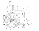
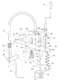
図1に示すように、車椅子(1)の車体レーム(F)に設けられた肘置き(17)近傍の操作ボックス(16)には操作レバー(15)が装備されていると共に、操作レバー(15)の操作力は、ワイヤ(151)を介して、左右の車輪(10)のハブ(H)に組み込まれた後述の逆回転防止装置(5)、回転力減衰装置(54)、及び、駐車時に使用するブレーキ装置(P)に伝達されるようになっている。
又、介助者用の手押ハンドル(18)に取り付けられたブレーキレバー(11)は、ケーブル(111)を介してハブ(H)に組み込まれた前記ブレーキ装置(P)に繋がっている。
The best mode for carrying out the present invention will be described below with reference to the accompanying drawings.
[Composition of wheelchair]
As shown in FIG. 1, the operation box (16) in the vicinity of the elbow rest (17) provided on the body frame (F) of the wheelchair (1) is equipped with an operation lever (15) and an operation lever ( The operating force of 15) is, via a wire (151), a reverse rotation prevention device (5), a rotational force damping device (54), which will be described later, incorporated in the hub (H) of the left and right wheels (10), and It is transmitted to the brake device (P) used when parking.
The brake lever (11) attached to the handwheel (18) for the assistant is connected to the brake device (P) incorporated in the hub (H) via the cable (111).
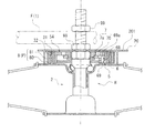
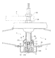
図3は、回転力減衰装置(54)の配設部の断面(左半分)と、逆回転防止装置(5)の配設部の断面(右半分)を表した、断面図である。
図3に示すように、ハブ(H)は車椅子(1)の車体フレーム(F)にナット(99)(99)で取り付けられていると共に、ハブ体(2)の一端には、車椅子(1)の肘置き(17)の近傍に設けられた操作レバー(15)やブレーキレバー(11)で操作されるブレーキ装置(P)と、上り坂での車椅子(1)の後退を防止する為の逆回転防止装置(5)と、下り坂での車椅子の暴走を防止する為の回転力減衰装置(54)が設けられている。以下、更に説明する。
FIG. 3 is a cross-sectional view showing a cross section (left half) of the arrangement portion of the rotational force damping device (54) and a cross section (right half) of the arrangement portion of the reverse rotation prevention device (5).
As shown in FIG. 3, the hub (H) is attached to the vehicle body frame (F) of the wheelchair (1) with nuts (99) and (99), and the wheelchair (1) is attached to one end of the hub body (2). ) To prevent retraction of the wheelchair (1) on the uphill and the brake device (P) operated by the operating lever (15) and brake lever (11) provided near the elbow rest (17) A reverse rotation prevention device (5) and a rotational force damping device (54) for preventing wheelchair runaway on a downhill are provided. This will be further described below.
[ハブ(H)の構成]
図2に示すように、ハブ(H)は、ハブ軸(22)と、これに対してベアリング(23)で回転自在に支持されるハブ体(2)を備えている。
ハブ軸(22)に外嵌されたベアリング(23)は、玉押し(24)及び玉押しナット(25)によってハブ体(2)側に押し付けられ、これにより、ハブ体(2)はハブ軸(22)に回転自在に保持される。
[Hub (H) configuration]
As shown in FIG. 2, the hub (H) includes a hub shaft (22) and a hub body (2) that is rotatably supported by a bearing (23).
The bearing (23) externally fitted to the hub axle (22) is pressed against the hub body (2) by the ball pusher (24) and the ball push nut (25), whereby the hub body (2) is pushed to the hub axle. (22) is rotatably held.
ハブ体(2)の外端に形成されたハブフランジ(28)の外周近傍には、多数のスポーク孔(26)が周方向に所定ピッチで穿設されており、各スポーク孔(26)に一端が係合されるスポーク(S)の他端はリム(R)(図1参照)に結合されている。 In the vicinity of the outer periphery of the hub flange (28) formed at the outer end of the hub body (2), a large number of spoke holes (26) are formed at a predetermined pitch in the circumferential direction, and each spoke hole (26) The other end of the spoke (S) with which one end is engaged is coupled to the rim (R) (see FIG. 1).
又、ハブ(H)の内端を覆うブレーキカバー(4)の裏面には、前記逆回転防止装置(5)、回転力減衰装置(54)及び、ブレーキ装置(P)を択一的に作動させる為の切替器(A)が設けられている(図5参照)。 The reverse rotation prevention device (5), the rotational force damping device (54), and the brake device (P) are alternatively operated on the back surface of the brake cover (4) covering the inner end of the hub (H). A switching device (A) is provided (see FIG. 5).
《ブレーキ装置(P)について》
車椅子(1)の肘置き(17)近傍の操作レバー(15)や、ブレーキレバー(11)で操作されるブレーキ装置(P)は、図2,3に示すように、ハブ体(2)の端部に一体形成されたブレーキドラム(3)の円筒状のドラム主体(31)の外周をブレーキバンド(8)で巻き締める機能を有している。
<About brake device (P)>
As shown in FIGS. 2 and 3, the operation lever (15) near the elbow rest (17) of the wheelchair (1) and the brake device (P) operated by the brake lever (11) The brake drum (3) integrally formed at the end has a function of tightening the outer periphery of the cylindrical drum main body (31) with the brake band (8).
ドラム主体(31)の一端はベース部(30)で閉塞されていると共に、ブレーキドラム(3)の外周に張り出したハブフランジ(20)には、既述ハブフランジ(28)と同様、所定ピッチでスポーク孔(201)が穿設されている。
図2〜4に示すように、ブレーキバンド(8)は、ドラム主体(31)の外周面(32)に沿って湾曲したブレーキシュー(80)の内周面にブレーキライニング(81)を添設したものである。
One end of the drum main body (31) is closed by the base portion (30), and the hub flange (20) projecting to the outer periphery of the brake drum (3) has a predetermined pitch like the hub flange (28) described above. The spoke hole (201) is drilled.
As shown in FIGS. 2 to 4, the brake band (8) has a brake lining (81) attached to the inner peripheral surface of the brake shoe (80) curved along the outer peripheral surface (32) of the drum main body (31). It is a thing.
一方、ハブ体(2)の前記ハブフランジ(20)側の端部を覆うように配設されるブレーキカバー(4)の下部には、ブレーキバンド(8)の一端をドラム主体(31)に接近させる為の第1クランク(84a)が支軸(85a)で回動自在に取り付けられていると共に、前記第1クランク(84a)の回動動先端部で押されることにより支軸(85b)を支点に回動する第2クランク(84b)が設けられており、第2クランク(84b)の回動によってブレーキバンド(8)の他端がドラム主体(31)に接近されるようになっている。第1クランク(84a)は、手押しハンドル(18)に取り付けられたブレーキレバー(11)から延びるケーブル(111)で一端が牽引されて回動すると共に、車椅子(1)の肘置き(17)近傍の操作レバー(15)に連動する牽引棒(51)(図5参照)で牽引されることによっても回動する。尚、操作レバー(15)と牽引棒(51)の連動機構は後述する。 On the other hand, at the lower part of the brake cover (4) disposed so as to cover the end of the hub body (2) on the hub flange (20) side, one end of the brake band (8) is attached to the drum main body (31). A first crank (84a) for approaching is pivotally attached to a support shaft (85a), and the support shaft (85b) is pushed by a rotating movement tip of the first crank (84a). A second crank (84b) is provided that rotates about the fulcrum, and the other end of the brake band (8) is brought closer to the drum main body (31) by the rotation of the second crank (84b). Yes. The first crank (84a) is rotated by being pulled by one end of a cable (111) extending from a brake lever (11) attached to a push handle (18), and in the vicinity of an elbow rest (17) of the wheelchair (1). It is also rotated by being pulled by a pulling rod (51) (see FIG. 5) interlocked with the operation lever (15). The interlocking mechanism between the operation lever (15) and the tow bar (51) will be described later.
このものでは、第1クランク(84a)や第2クランク(84b)によって、既述ブレーキバンド(8)の両端がブレーキドラム(3)のドラム主体(31)に接離する方向に往復移動され、これにより、ブレーキドラム(3)のドラム主体(31)がブレーキバンド(8)で巻き締められて制動される。 In this case, the first crank (84a) and the second crank (84b) reciprocate both ends of the brake band (8) in the direction of coming into contact with and separating from the drum main body (31) of the brake drum (3). Thereby, the drum main body (31) of the brake drum (3) is wound and braked by the brake band (8).
《逆回転防止装置(5)について》
図2に示すように、逆回転防止装置(5)は、ブレーキドラム(3)のドラム主体(31)の内周面を突っ張る様に押圧した状態(クサビ係合状態)になる一対の制動アーム(6)と、前記クサビ係合状態を解除させる方向に制動アーム(6)を回動させる切替リング(7)とを具備しており、これら制動アーム(6)や切替リング(7)はブレーキドラム(3)の内部に配設される。
《About reverse rotation prevention device (5)》
As shown in FIG. 2, the reverse rotation prevention device (5) has a pair of braking arms that are pressed so as to stretch the inner peripheral surface of the drum main body (31) of the brake drum (3) (wedge engagement state). (6) and a switching ring (7) for rotating the braking arm (6) in a direction to release the wedge engagement state, and the braking arm (6) and the switching ring (7) Arranged inside the drum (3).
切替リング(7)を回動自在に支持する支持円盤(73)は、切替リング(7)が回動自在に外嵌する小径筒(73a)とその基端部に続く大径筒(73b)からなる中空の段付き筒であり、大径筒(73b)と環状押え板(74)で切替リング(7)の内周部が緩く挟まれるようになっている。 A support disk (73) that rotatably supports the switching ring (7) includes a small-diameter cylinder (73a) on which the switching ring (7) is rotatably fitted and a large-diameter cylinder (73b) that follows the base end portion. This is a hollow stepped cylinder made of, and the inner periphery of the switching ring (7) is loosely sandwiched between the large diameter cylinder (73b) and the annular presser plate (74).
切替リング(7)の上に重ねられる一対の制動アーム(6)は、ドラム主体(31)の内周面(33)に沿って180度ピッチで配設されており、各制動アーム(6)の回動支点には支持孔(6b)(ブレーキカバー(4)から突出する後述の支柱(600a)又は支柱(600b)に回動自在に外嵌する)が穿設され、反対側の回動先端部(61)にはピン孔(68)が穿設されている。このピン孔(68)には、ドラム主体(31)の内周面(33)に沿う円弧状のブレーキシュー(67)(外周に制動ライニング(60)が添設されている)の周方向中央部に穿設された結合孔(670)が重ねられ、この重ね合わせ部に結合ピン(69)が挿入されるようになっている。これにより、ブレーキシュー(67)が結合ピン(69)を介して制動アーム(6)に首振り自在に結合される。 A pair of braking arms (6) overlaid on the switching ring (7) are arranged at a pitch of 180 degrees along the inner peripheral surface (33) of the drum main body (31), and each braking arm (6) The support fulcrum (6b) is drilled at the pivot fulcrum (which will be pivotally fitted to a support column (600a) or support column (600b), which will be described later) that protrudes from the brake cover (4). A pin hole (68) is formed in the tip (61). The pin hole (68) has an arcuate brake shoe (67) along the inner peripheral surface (33) of the drum main body (31) (circumferential center of the brake lining (60) attached to the outer periphery). The coupling hole (670) drilled in the part is overlapped, and the coupling pin (69) is inserted into the overlapping part. Thus, the brake shoe (67) is swingably coupled to the brake arm (6) via the coupling pin (69).
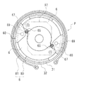
図2,図4に示すように、各制動アーム(6)の周方向の端部の相互間には、バネ常数の小さなバネ(65)が圧縮状態で介装されており、これにより、逆回転防止装置(5)を作動させた状態では、ブレーキシュー(67)の外周の制動ライニング(60)が、ドラム主体(31)の内周面(33)に弱い力で当接されるようになっている。 As shown in FIGS. 2 and 4, a spring (65) having a small spring constant is interposed in a compressed state between the circumferential ends of each brake arm (6). When the anti-rotation device (5) is activated, the brake lining (60) on the outer periphery of the brake shoe (67) is brought into contact with the inner peripheral surface (33) of the drum main body (31) with a weak force. It has become.
各制動アーム(6)をドラム主体(31)から離反させる方向に回動させる切替リング(7)は、環状平板(7a)の外周から180度ピッチで一対の解放腕(70)を突設させた構成である。各解放腕(70)は、図2,図3に示すように、制動アーム(6)の回動先端部(61)のピン孔(68)から裏側に突出する結合ピン(69)の係合突出部(69a)の外周に係合するようになっている。又、一方の解放腕(70)には、車椅子(1)の肘置き(17)近傍の操作レバー(15)の操作力が伝達される操作ピン(71)が突設されており、操作レバー(15)の操作により切替リング(7)の周方向に操作ピン(71)が引っ張られると、切替リング(7)が回動してその解放腕(70)が制動アーム(6)の回動先端部(61)に貫通する結合ピン(69)に係合し、これにより、各制動アーム(6)の両回動先端部(61)(61)がバネ(65)の付勢力に抗して接近する。 The switching ring (7) for rotating each brake arm (6) in the direction away from the drum main body (31) causes a pair of release arms (70) to project from the outer periphery of the annular flat plate (7a) at a pitch of 180 degrees. It is a configuration. As shown in FIGS. 2 and 3, each release arm (70) is engaged with a coupling pin (69) that protrudes from the pin hole (68) of the rotating tip (61) of the braking arm (6). The protrusion (69a) is engaged with the outer periphery. In addition, one release arm (70) is provided with an operation pin (71) that projects the operation force of the operation lever (15) in the vicinity of the elbow rest (17) of the wheelchair (1). When the operation pin (71) is pulled in the circumferential direction of the switching ring (7) by the operation of (15), the switching ring (7) rotates and its release arm (70) rotates the braking arm (6). Engage with the connecting pin (69) penetrating the tip (61), so that the rotating tip (61) (61) of each brake arm (6) resists the biasing force of the spring (65). Approach.
《回転力減衰装置(54)について》
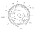
図2に示すように、回転力減衰装置(54)は、ブレーキドラム(3)のドラム主体(31)の内周面(33)に対して接触・離反する摩擦ライニング(101)が外面に添設された円弧板(102)が一体化された一対の抵抗付与アーム(100)(100)を具備している。そして、これら抵抗付与アーム(100)(100)は、ブレーキドラム(3)内に配設されるようになっている。
《About rotational force damping device (54)》
As shown in FIG. 2, the rotational force damping device (54) has a friction lining (101) that contacts and separates from the inner peripheral surface (33) of the drum main body (31) of the brake drum (3) attached to the outer surface. A pair of resistance applying arms (100) and (100) are integrated with a circular arc plate (102) provided. These resistance applying arms (100) (100) are arranged in the brake drum (3).
抵抗付与アーム(100)(100)の基端部(103)(103)には軸孔(105)(105)が穿設されており、ブレーキカバー(4)の底板(42)に突設された支軸(104)に前記軸孔(105)(105)が回動自在に外嵌された状態にてビス(113)(支軸(104)の先端に螺入される)で固定されるようになっている。又、各抵抗付与アーム(100)の自由端部(107)の近傍には、これら両抵抗付与アーム(100)(100)を接近させる方向に付勢する解除バネ(112)の両端を引っ掛ける係合孔(100a)(100a)が形成されている。 A shaft hole (105) (105) is drilled in the base end (103) (103) of the resistance applying arm (100) (100) and protrudes from the bottom plate (42) of the brake cover (4). The shaft hole (105) (105) is rotatably fitted to the support shaft (104) and fixed with screws (113) (screwed into the tip of the support shaft (104)). It is like that. Further, in the vicinity of the free end portion (107) of each resistance applying arm (100), both ends of a release spring (112) that urges the two resistance applying arms (100) and (100) in a direction approaching each other are hooked. Joint holes (100a) (100a) are formed.
一方の抵抗付与アーム(100)には、その基端部(103)近傍の軸孔(105)に隣接させて周方向に延びる長孔(106)が形成されており、該長孔(106)はブレーキカバー(4)の底板(42)に形成された長孔(402)に対向している。そして、既述逆回転防止装置(5)を構成する切替リング(7)の解放腕(70)に突設された操作ピン(71)は、長孔(106)(402)を介してブレーキカバー(4)の外部に突出するように構成されている。又、一方の抵抗付与アーム(100)の自由端部(107)の近傍には、ブレーキカバー(4)の底板(42)に突設された支柱(600a)(先端にはネジ孔(n)が形成されている)にルーズに外嵌する軸挿通孔(108)が形成されている。 One resistance applying arm (100) is formed with a long hole (106) extending in the circumferential direction adjacent to the shaft hole (105) in the vicinity of the base end (103), and the long hole (106). Is opposed to a long hole (402) formed in the bottom plate (42) of the brake cover (4). The operation pin (71) protruding from the release arm (70) of the switching ring (7) constituting the reverse rotation prevention device (5) described above is connected to the brake cover via the long holes (106) (402). It is configured to protrude outside (4). Also, in the vicinity of the free end (107) of one resistance applying arm (100), there is a column (600a) protruding from the bottom plate (42) of the brake cover (4) (screw hole (n) at the tip) A shaft insertion hole (108) that fits loosely is formed.
他方の抵抗付与アーム(100)には、その基端部(103)の近傍の軸孔(105)に隣接させて軸挿通孔(109)が形成されており、該軸挿通孔(109)は、ブレーキカバー(4)の底板(42)に突設された支柱(600b)(先端にはネジ孔(n)が形成されている)にルーズに外嵌するようになっている。 The other resistance applying arm (100) has a shaft insertion hole (109) formed adjacent to the shaft hole (105) in the vicinity of the base end portion (103), and the shaft insertion hole (109) The brake cover (4) is loosely fitted on a column (600b) (a screw hole (n) is formed at the tip) protruding from the bottom plate (42) of the brake cover (4).
従って、上記支柱(600a)(600b)に、一方の抵抗付与アーム(100)に形成された軸挿通孔(108)と他方の抵抗付与アーム(100)に形成された軸挿通孔(109)を各別に外嵌させ、更に、これら軸挿通孔(108)(109)から突出する支柱(600a)(600b)の先端に、各制動アーム(6)の回動支点側に形成された支持孔(6b)を外嵌させ、その後、押え板(97)の透孔(970)(970)越しにビス(93)(93)を支柱(600a)(600b)先端のネジ孔(n)(n)にネジ込むと、各制動アーム(6)が回転力減衰装置(54)の各抵抗付与アーム(100)上に重なった状態で、支柱(600a)(600b)に回動自在に支持される。尚、前記押え板(97)の中央孔(971)は、ハブ軸(22)を挿通させる孔である。 Therefore, the column (600a) (600b) has a shaft insertion hole (108) formed in one resistance applying arm (100) and a shaft insertion hole (109) formed in the other resistance applying arm (100). Further, a support hole formed on the rotation fulcrum side of each brake arm (6) at the tip of the pillars (600a) and (600b) protruding from the shaft insertion holes (108) and (109). 6b), and then screw (93) (93) through the hole (970) (970) of the presser plate (97) and screw hole (n) (n) at the tip of the column (600a) (600b) Then, each brake arm (6) is rotatably supported by the columns (600a) and (600b) in a state where each brake arm (6) is superimposed on each resistance applying arm (100) of the rotational force damping device (54). The center hole (971) of the pressing plate (97) is a hole through which the hub shaft (22) is inserted.
図2,図8に示すように、回転力減衰装置(54)を構成する各抵抗付与アーム(100)の自由端部(107)(107)の相互は、これらの間に設けられた楕円板状の回動カム(91)を径方向から挟圧するように対向しており、回動カム(91)に固定されたカム軸(92)は、ブレーキカバー(4)の底板(42)に形成された透孔(423)に挿通されて外部に突出するようになっている。尚、ブレーキカバー(4)の底板(42)の中央には、ハブ軸(22)を挿通させる軸孔(429)が開設されている。 As shown in FIGS. 2 and 8, the free end portions (107) and (107) of the resistance applying arms (100) constituting the rotational force attenuating device (54) are elliptical plates provided therebetween. The cam shaft (92) fixed to the rotating cam (91) is formed on the bottom plate (42) of the brake cover (4). It is inserted through the formed through hole (423) and protrudes to the outside. A shaft hole (429) through which the hub shaft (22) is inserted is formed at the center of the bottom plate (42) of the brake cover (4).
図5に示すように、上記透孔(423)からブレーキカバー(4)の外部に突出したカム軸(92)には、回動カム(91)を回動させる為の解除レバー(94)の一端が固定されていると共に、該解除レバー(94)の他端は、これを引き上げるワイヤ(W1)に外嵌した圧縮バネ(940)で下方に付勢されている。又、ワイヤ(W1)を挿通させるアウタチューブ(72)の一端に固定されたネジ筒(720)は、ブレーキカバー(4)から突出する取付アーム(424)の水平板部(425)に螺入されて下方に突出していると共に、ネジ筒(720)の下端には、圧縮バネ(940)の圧縮量を調節する圧縮量調節ネジ(941)が螺合されている。 As shown in FIG. 5, the cam shaft (92) protruding from the through hole (423) to the outside of the brake cover (4) has a release lever (94) for rotating the rotating cam (91). One end is fixed, and the other end of the release lever (94) is urged downward by a compression spring (940) externally fitted to a wire (W1) for pulling up the release lever (94). The screw cylinder (720) fixed to one end of the outer tube (72) through which the wire (W1) is inserted is screwed into the horizontal plate portion (425) of the mounting arm (424) protruding from the brake cover (4). In addition, the compression amount adjusting screw (941) for adjusting the compression amount of the compression spring (940) is screwed into the lower end of the screw cylinder (720).
このものでは、解除レバー(94)の先端がワイヤ(W1)で引き上げられると、各抵抗付与アーム(100)の自由端部(107)を相互に離反させる為の回動カム(91)が回動して図8の姿勢になり、これにより、各抵抗付与アーム(100)が解除バネ(112)の付勢力で接近方向に回動する。すると、抵抗付与アーム(100)に設けられた摩擦ライニング(101)がドラム主体(31)の内周面(33)から離反して、これら両者間に隙間(G)が形成される(図8参照)。これにより、ブレーキドラム(3)のドラム主体(31)と抵抗付与アーム(100)の摩擦ライニング(101)が摩擦接触せず、ハブ体(2)とハブ軸(22)とが自由に相対回転し得る状態になる。即ち、平坦面での車椅子の円滑な走行が可能となる。 In this case, when the tip of the release lever (94) is pulled up by the wire (W1), the rotating cam (91) for separating the free ends (107) of the resistance applying arms (100) from each other is rotated. 8, and each resistance applying arm (100) is rotated in the approaching direction by the urging force of the release spring (112). Then, the friction lining (101) provided on the resistance applying arm (100) is separated from the inner peripheral surface (33) of the drum main body (31), and a gap (G) is formed between them (FIG. 8). reference). As a result, the drum main body (31) of the brake drum (3) and the friction lining (101) of the resistance applying arm (100) are not in frictional contact, and the hub body (2) and the hub shaft (22) are freely rotated relative to each other. It will be in a state that can. That is, the wheelchair can smoothly run on a flat surface.
一方、解除レバー(94)が下方に回動すると、カム軸(92)に連設された回動カム(91)が、一対の抵抗付与アーム(100)の自由端部(107)を相互に離反させる方向に回動する。すると、各抵抗付与アーム(100)が基端部(103)側を支点として前記離反する方向に回動し、これにより、各抵抗付与アーム(100)の外周部に設けた円弧板(102)の外面の摩擦ライニング(101)(101)とブレーキドラム(3)のドラム主体(31)の内周面(33)の隙間(G)(G)(図8参照)が消失する。これにより、上記摩擦ライニング(101)とドラム主体(31)の内周面が摩擦接触してハブ体(2)の回転に抵抗を与え、下り坂での車椅子の暴走を防止することができる。 On the other hand, when the release lever (94) pivots downward, the pivot cam (91) connected to the cam shaft (92) causes the free end portions (107) of the pair of resistance applying arms (100) to cross each other. It rotates in the direction to separate. Then, each resistance applying arm (100) pivots in the direction of separation with the base end (103) side as a fulcrum, thereby, the arc plate (102) provided on the outer peripheral portion of each resistance applying arm (100) The gaps (G) and (G) (see FIG. 8) between the friction linings (101) and (101) on the outer surface of the drum and the inner peripheral surface (33) of the drum main body (31) of the brake drum (3) disappear. As a result, the friction lining (101) and the inner peripheral surface of the drum main body (31) are in frictional contact to provide resistance to the rotation of the hub body (2), thereby preventing the wheelchair from running down on the downhill.
このものでは、ブレーキドラム(3)の内周面に対して摩擦接触状態になる摩擦抵抗付与手段(摩擦ライニング(101)を具備する抵抗付与アーム(100))によって、ハブ体(2)の回転を減衰させるようにしたからら、季節の移り変わり等に基づく外気温変化で粘性抵抗が変化するオイルダンパを用いる既述従来のものと相違し、外気温変化に関わらず、回転力減衰装置(54)の安定性能が確保できる。 In this device, the hub body (2) is rotated by friction resistance applying means (resistance applying arm (100) having a friction lining (101)) that is in frictional contact with the inner peripheral surface of the brake drum (3). In contrast to the conventional one that uses an oil damper whose viscosity resistance changes due to changes in the outside air temperature due to seasonal changes, etc., the rotational force damping device (54 ) Stable performance can be secured.
又、本実施の形態に係る自転車用ハブに組み込まれた回転力減衰装置(54)では、圧縮量調節ネジ(941)で圧縮バネ(940)の圧縮量を調節すると、各抵抗付与アーム(100)の自由端部(107)相互を回動カム(91)で離反させる力が調節できる。具体的には、圧縮量調節ネジ(941)で圧縮バネ(940)の圧縮量を増加させると、該圧縮バネ(940)の付勢力が増加し、これにより、各抵抗付与アーム(100)の自由端部(107)相互を回動カム(91)で離反させる力が増加する。これとは逆に圧縮バネ(940)の圧縮量を減少させると、前記離反させる力が低下する。これにより、上記調節が行える。 Further, in the rotational force damping device (54) incorporated in the bicycle hub according to the present embodiment, when the compression amount of the compression spring (940) is adjusted by the compression amount adjusting screw (941), each resistance applying arm (100 ) Can be adjusted to separate the free ends (107) of each other by the rotating cam (91). Specifically, when the compression amount of the compression spring (940) is increased by the compression amount adjusting screw (941), the urging force of the compression spring (940) increases, and thereby, each resistance applying arm (100) The force for separating the free ends (107) from each other by the rotating cam (91) increases. On the contrary, if the compression amount of the compression spring (940) is decreased, the separating force is reduced. Thereby, the adjustment can be performed.
これにより、各抵抗付与アーム(100)に設けられた摩擦ライニング(101)がブレーキドラム(3)のドラム主体(31)の内周面(33)に押圧される力を調節することができ、ハブ体(2)とハブ軸(22)の相対回転に対する抵抗を適正な大きさに設定できる。即ち、回転力減衰装置(54)の性能調節が可能となる。 Thereby, it is possible to adjust the force that the friction lining (101) provided on each resistance applying arm (100) is pressed against the inner peripheral surface (33) of the drum main body (31) of the brake drum (3), The resistance against relative rotation of the hub body (2) and the hub shaft (22) can be set to an appropriate size. That is, it is possible to adjust the performance of the rotational force damping device (54).
《切替器(A)について》
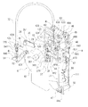
上記逆回転防止装置(5)、回転力減衰装置(54)及び、ブレーキ装置(P)を択一的に作動させる為の切替器(A)は、図5,図6に示す構造を有している。
ブレーキカバー(4)の底板(42)の裏面上部には、切替レバー(35)の回動支点(351)がボルト(36)で回動自在に支持されていると共に、切替レバー(35)の回動端にはワイヤ(151)(操作レバー(15)に繋がっている)が接続されている。そして、ワイヤ(151)で引き上げられて切替レバー(35)が回動すると、切替レバー(35)の回動角度に応じて逆回転防止装置(5)、回転力減衰装置(54)及び、ブレーキ装置(P)が作動するようになっている。
<About switch (A)>
The switch (A) for selectively operating the reverse rotation prevention device (5), the rotational force damping device (54), and the brake device (P) has the structure shown in FIGS. ing.
On the upper surface of the bottom surface of the bottom plate (42) of the brake cover (4), a rotation fulcrum (351) of the switching lever (35) is rotatably supported by a bolt (36), and the switching lever (35) A wire (151) (connected to the operation lever (15)) is connected to the rotating end. Then, when the switching lever (35) is rotated by being pulled up by the wire (151), the reverse rotation prevention device (5), the rotational force damping device (54), and the brake according to the rotation angle of the switching lever (35) The device (P) is activated.
*ブレーキ装置(P)の切替部
ブレーキ装置(P)は、図5,図6に示すように、既述ブレーキバンド(8)の端部を引っ張る第1クランク(84a)によって、作動状態と非作動状態に切り替えられる。第1クランク(84a)の入力端に固定されたアングル部材(82)には、牽引棒(51)の下端が上下に貫通していると共に、該牽引棒(51)は、下端に螺合されたアンカーナット(87)でアングル部材(82)に結合されている。牽引棒(51)は、ブレーキカバー(4)の底板(42)裏面に立設された一対の平行な起立板(46)(47)に形成された透孔(460)(470)に対して摺動自在に挿通され、牽引棒(51)に螺合されたバネ受けブロック(48)とその上方の起立板(46)の間には、圧縮バネ(49)が介装されている。バネ受けブロック(48)に螺合されたビス(480)の頭部(481)は、図6に示すように、前記起立板(46)(47)の相互間を覆う切替具用カバー(40)のスリット(404)から上方に突出しており、該突出した頭部(481)は、切替レバー(35)の側縁に押されて移動する構造である。
* Switching part of brake device (P) As shown in FIGS. 5 and 6, the brake device (P) is operated and not operated by the first crank (84a) that pulls the end of the brake band (8). Switch to the operating state. The angle member (82) fixed to the input end of the first crank (84a) has the lower end of the tow bar (51) vertically penetrated, and the tow bar (51) is screwed to the lower end. It is connected to the angle member (82) by an anchor nut (87). The tow bar (51) is against a through hole (460) (470) formed in a pair of parallel upright plates (46) (47) erected on the back surface of the bottom plate (42) of the brake cover (4). A compression spring (49) is interposed between a spring receiving block (48) that is slidably inserted and screwed into the pulling rod (51) and an upright plate (46) thereabove. As shown in FIG. 6, the head portion (481) of the screw (480) screwed into the spring receiving block (48) has a switching tool cover (40) covering between the upright plates (46) (47). ) Projecting upward from the slit (404), and the projecting head (481) is pushed and moved by the side edge of the switching lever (35).
*回転力減衰装置(54)の切替部
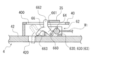
回転力減衰装置(54)の解除レバー(94)に一端が連結されたワイヤ(W1)の他端を引っ張るワイヤ牽引具(62)は、図5,図7に示すように、一対の平行板(630)(630)を具備する断面U状のスライダー(63)と、前記平行板(630)(630)に回動自在に支持されたワイヤ固定軸(64)(ワイヤ(W1)が連結されている。)を具備していると共に、平行板(630)(630)には、λ状のアンカー板(66)の下部が軸(660)で回動自在に取り付けられている。アンカー板(66)は、軸(660)が貫通する回動脚(661)と、その先端から上下に分岐した頭部(662)及び係合脚(663)を具備しており、係合脚(663)はブレーキカバー(4)の底板(42)に開設された係合孔(420)に係脱するようになっている。
* Switching part of the rotational force damping device (54) The wire puller (62) for pulling the other end of the wire (W1) connected at one end to the release lever (94) of the rotational force damping device (54) is shown in FIG. As shown in FIG. 7, a slider (63) having a U-shaped section having a pair of parallel plates (630) and (630), and a wire fixing shaft rotatably supported by the parallel plates (630) and (630) (64) (the wire (W1) is connected) and the lower part of the λ-shaped anchor plate (66) is rotated by the shaft (660) on the parallel plates (630) and (630). It is attached movably. The anchor plate (66) includes a rotating leg (661) through which the shaft (660) passes, a head (662) branched from the tip thereof up and down, and an engaging leg (663). ) Is engaged with and disengaged from the engagement hole (420) formed in the bottom plate (42) of the brake cover (4).
又、上記アンカー板(66)の頭部(662)は、図6,図7に示すように、ブレーキカバー(4)の裏面に設けれた切替具用カバー(40)のスリット(400)から上方に突出しており、突出した頭部(662)が切替レバー(35)の側縁に押されて移動する構造である。 Further, the head portion (662) of the anchor plate (66) is, as shown in FIGS. 6 and 7, from the slit (400) of the switch cover (40) provided on the back surface of the brake cover (4). It protrudes upward, and the protruding head (662) moves by being pushed by the side edge of the switching lever (35).
*逆回転防止装置(5)の切替部
逆回転防止装置(5)は、図5,図6に示すように、既述した切替リング(7)の外周に突出する解放腕(70)に設けられた操作ピン(71)を引っ張るブロック(37)の往復移動によって、作動状態と非作動状態に切り替えられる。
* Switching part of reverse rotation prevention device (5) As shown in FIGS. 5 and 6, the reverse rotation prevention device (5) is provided on the release arm (70) protruding from the outer periphery of the switching ring (7) described above. By switching the block (37) that pulls the operating pin (71), the operation pin (71) is switched between the operating state and the non-operating state.
ブロック(37)には、上記操作ピン(71)に外嵌する長孔(370)が表裏に貫通していると共に、該ブロック(37)はL字状のブロック取付板(38)に固定されている。ブロック取付板(38)には、これを引き上げる牽引棒(39)の下端が、該下端に螺合されたナット(381)で連結されており、ブロック取付板(38)は圧縮バネ(391)で下方に押されている。 The block (37) has a long hole (370) that fits outside the operation pin (71) through the front and back, and the block (37) is fixed to an L-shaped block mounting plate (38). ing. The block mounting plate (38) is connected to the lower end of a pulling rod (39) for pulling it up by a nut (381) screwed to the lower end, and the block mounting plate (38) is a compression spring (391). Is pushed downward.
牽引棒(39)は、ブレーキカバー(4)の裏面に立設する下側の起立板(47)に形成された透孔(471)に対して摺動自在に挿通されている。牽引棒(39)の上端は、既述ワイヤ牽引具(62)と同様の構造を有する牽引具(12)の下端ブロック(120)に螺入結合されている。そして、牽引具(12)に軸(121)で回動自在に支持されたアンカー板(13)の一端の係合脚部(133)は、牽引具(12)の上下移動に伴って、ブレーキカバー(4)の底板(42)に開設され係合孔(426)に係脱するようになっている。 The tow bar (39) is slidably inserted into a through hole (471) formed in a lower upright plate (47) standing on the back surface of the brake cover (4). The upper end of the tow bar (39) is screwed and coupled to the lower end block (120) of the tow tool (12) having the same structure as the wire tow tool (62) described above. Then, the engaging leg (133) at one end of the anchor plate (13) rotatably supported by the traction tool (12) by the shaft (121) is moved along with the vertical movement of the traction tool (12). It is opened on the bottom plate (42) of (4), and is engaged with and disengaged from the engagement hole (426).
*切替レバー(35)について
図6に示すように、ブレーキカバー(4)の底板(42)に回動自在に支持された切替レバー(35)は、ボルト(36)側に位置する基端腕(352)に続く屈曲起立部(353)(図6に於いて紙面の手前へ屈曲起立している)の上端から水平アーム部(354)が屈曲した構成であり、水平アーム部(354)は切替具用カバー(40)の上面に沿って回動するようになっている。水平アーム部(354)の一方の側縁には、ブレーキ装置(P)を作動させる牽引棒(51)に連設されたビス(480)の頭部(481)が係合する係合凹部(355)が形成されている。
* Switching lever (35) As shown in FIG. 6, the switching lever (35) supported rotatably on the bottom plate (42) of the brake cover (4) is a proximal arm located on the bolt (36) side. The horizontal arm portion (354) is bent from the upper end of the bent upright portion (353) following (352) (bending upright in FIG. 6). The horizontal arm portion (354) It is designed to rotate along the upper surface of the switch tool cover (40). On one side edge of the horizontal arm portion (354), an engagement recess (with a head (481) of a screw (480) connected to a tow bar (51) for operating the brake device (P) engages ( 355) is formed.
切替レバー(35)の回動先端部近傍には、車椅子(1)の肘置き(17)近傍の操作レバー(15)で引っ張られるワイヤ(151)の先端がジョイント(152)で結合されていると共に、切替レバー(35)の回動先端部の小孔(356)とブレーキカバー(4)の底板(42)に植設されたバネ掛けピン(421)には引っ張りバネ(98)が架設されている。 Near the turning tip of the switching lever (35), the tip of the wire (151) pulled by the operation lever (15) near the elbow rest (17) of the wheelchair (1) is joined by a joint (152). At the same time, a tension spring (98) is installed in the small hole (356) at the rotating tip of the switching lever (35) and the spring hook pin (421) planted in the bottom plate (42) of the brake cover (4). ing.
[操作レバー(15)及び操作ボックス(16)]
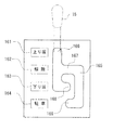
車椅子(1)の肘置き(17)の近傍に配設された操作ボックス(16)(図1参照)の上面には、図9に示すように、上り坂表示部(161)と、解除表示部(162)と、下り坂表示部(163)と、更に、駐車表示部(164)が前方からこの順序で表示されている。そして、これら上り坂表示部(161)〜駐車表示部(164)の側方の操作ボックス(16)上壁には、これら上り坂表示部(161)〜駐車表示部(164)の側方位置に操作レバー(15)を切り替える為の屈曲したレバーガイド溝(165)が開設されている。レバーガイド溝(165)の途中には、操作レバー(15)を上り坂表示部(161)〜駐車表示部(164)の側方に保持する為の第1係合凹部(166)と、第2係合水平部(167)と、第3係合凹部(168)と、第4係合凹部(169)が設けられている。
又、操作レバー(15)の回動操作力は、図1に現れるワイヤ(151)を介して切替器(A)の切替レバー(35)に伝達されるようになっている。
[Control lever (15) and control box (16)]
As shown in FIG. 9, on the upper surface of the operation box 16 (see FIG. 1) arranged near the elbow rest (17) of the wheelchair (1), as shown in FIG. The part (162), the downhill display part (163), and the parking display part (164) are displayed in this order from the front. Then, on the upper wall of the operation box (16) on the side of the uphill display section (161) to the parking display section (164), the lateral position of the uphill display section (161) to the parking display section (164) A bent lever guide groove (165) for switching the operation lever (15) is provided. In the middle of the lever guide groove (165), a first engagement recess (166) for holding the operation lever (15) to the side of the uphill display part (161) to the parking display part (164), A two-engagement horizontal portion (167), a third engagement recess (168), and a fourth engagement recess (169) are provided.
The turning operation force of the operation lever (15) is transmitted to the switching lever (35) of the switching device (A) via the wire (151) appearing in FIG.
[動作説明]
次に、操作レバー(15)を操作して逆回転防止装置(5)、回転力減衰装置(54)、及びブレーキ装置(P)を作動させる場合の動作説明をする。
[Description of operation]
Next, the operation in the case where the operation lever (15) is operated to operate the reverse rotation prevention device (5), the rotational force damping device (54), and the brake device (P) will be described.
《パーキング動作》
先ず、駐車時にブレーキ装置(P)を作動させる場合を説明する。
操作レバー(15)を回動操作して駐車操作位置たる第4係合凹部(169)(図9参照)に係合させると、図5,図6に現れる切替レバー(35)がワイヤ(151)によって最上昇位置まで引き上げられる。すると、切替レバー(35)の上辺に形成された係合凹部(355)が牽引棒(51)の上部のバネ受けブロック(48)に設けられたビス(480)を引き上げ、ブレーキ装置(P)を作動させる為の第1クランク(84a)を上方に回動させる。すると、既述したように、第1クランク(84a)と第2クランク(84b)によってブレーキバンド(8)の両端がブレーキドラム(3)のドラム主体(31)に接近せしめられる。これにより、ドラム主体(31)がブレーキバンド(8)で巻き締められた状態に維持され、車輪(10)の回転が阻止された駐車状態になる。
<Parking operation>
First, the case where the brake device (P) is operated during parking will be described.
When the operating lever (15) is rotated and engaged with the fourth engaging recess (169) (see FIG. 9) which is the parking operation position, the switching lever (35) appearing in FIGS. ) Is pulled up to the highest position. Then, the engaging recess (355) formed on the upper side of the switching lever (35) pulls up the screw (480) provided on the spring receiving block (48) on the upper part of the tow bar (51), and the brake device (P) The first crank (84a) for operating is rotated upward. Then, as described above, both ends of the brake band (8) are brought close to the drum main body (31) of the brake drum (3) by the first crank (84a) and the second crank (84b). As a result, the drum main body (31) is maintained in a state of being tightened by the brake band (8), and a parking state in which the rotation of the wheel (10) is prevented is obtained.
一方、操作レバー(15)を前記第4係合凹部(169)から、図9に示す解除操作位置たる第2係合凹部(167)に回動させると、ワイヤ(151)の張力が低下し、これにより、切替レバー(35)が引っ張りバネ(98)の付勢力で下方に回動する。すると、図5に現れる牽引棒(51)が、これの上部に具備させたバネ受けブロック(48)を押圧する圧縮バネ(49)に押されて下方に移動し、これにより、上記第1クランク(84a)及び第2クランク(84b)がブレーキバンド(8)をドラム主体(31)から離反させる方向に回動し、駐車状態が解除される。 On the other hand, when the operation lever (15) is rotated from the fourth engagement recess (169) to the second engagement recess (167) as the release operation position shown in FIG. 9, the tension of the wire (151) decreases. Thereby, the switching lever (35) is rotated downward by the urging force of the tension spring (98). Then, the tow bar (51) appearing in FIG. 5 is moved downward by the compression spring (49) that presses the spring receiving block (48) provided on the upper part thereof, and thereby the first crank is moved. (84a) and the second crank (84b) rotate in a direction to separate the brake band (8) from the drum main body (31), and the parking state is released.
《回転力減衰動作》
次に、回転力減衰装置(54)を作動させる場合について説明する。
図9に示す解除操作位置たる第2係合凹部(167)に操作レバー(15)が係合している状態では、図5〜図7に現れる切替レバー(35)は、ワイヤ牽引具(62)のλ状のアンカー板(66)の頭部(662)を下方に押し、アンカー板(66)の係合脚(663)をブレーキカバー(4)の係合孔(420)に係合させた状態(図7の想像線の状態)に維持している。この状態では、ワイヤ牽引具(62)がワイヤ(W1)を牽引することにより、ワイヤ(W1)の他端に結合された解除レバー(94)の先端を引き上げた状態に維持している。この状態では、回転力減衰装置(54)を構成する各抵抗付与アーム(100)の自由端部(107)の相互間に介在された回動カム(91)が図8の姿勢にあり、抵抗付与アーム(100)の外周に設けられた摩擦ライニング(101)がブレーキドラム(3)のドラム主体(31)から離反した状態。即ち、回転力減衰装置(54)が非作動状態に維持され、これにより、平坦面での円滑走行が可能になる。
《Rotation force damping operation》
Next, a case where the rotational force damping device (54) is operated will be described.
In a state where the operation lever (15) is engaged with the second engagement recess (167) which is the release operation position shown in FIG. 9, the switching lever (35) appearing in FIGS. The head (662) of the λ-shaped anchor plate (66) is pushed downward, and the engagement leg (663) of the anchor plate (66) is engaged with the engagement hole (420) of the brake cover (4). The state is maintained (the state of the imaginary line in FIG. 7). In this state, the tip of the release lever (94) coupled to the other end of the wire (W1) is pulled up by the wire pulling tool (62) pulling the wire (W1). In this state, the rotating cam (91) interposed between the free ends (107) of the resistance applying arms (100) constituting the rotational force damping device (54) is in the posture shown in FIG. The friction lining (101) provided on the outer periphery of the applying arm (100) is separated from the drum main body (31) of the brake drum (3). That is, the rotational force attenuating device (54) is maintained in a non-operating state, thereby enabling smooth running on a flat surface.
一方、下り坂での暴走を防止すべく操作レバー(15)を下り坂操作位置たる第3係合凹部(168)に係合させると、切替レバー(35)が引っ張りバネ(98)の付勢力に抗してワイヤ(151)で引っ張られて上方に回動する。すると、ワイヤ(W1)の解除レバー(94)側に設けられた圧縮バネ(940)の付勢力が、前記ワイヤ(W1)を介してワイヤ牽引具(62)に伝達され、これにより、図7に示すワイヤ牽引具(62) が切替レバー(35)に追随して、同図の右方向に移動する。これにより、上記解除レバー(94)が圧縮バネ(940)の付勢力で下方に回動し、カム軸(92)に連設された回動カム(91)が、一対の抵抗付与アーム(100)の自由端部(107)を相互に離反させる。これにより、既述したように、各抵抗付与アーム(100)の外周部摩擦ライニング(101)がブレーキドラム(3)のドラム主体(31)の内周面(33)に摩擦接触し、ハブ体(2)の回転に抵抗を与え、下り坂での車椅子の暴走を防止することができる。
尚、回転力減衰装置(54)が作動した状態では、逆回転防止装置(5)を作動させる為の牽引具(12)は切替レバー(35)で上方へ押されていない。従って、後述するように、逆回転防止装置(5)は非作動状態に維持され、下り坂を、前向き及び後ろ向きの何れの姿勢で下ることもできる。
On the other hand, when the operating lever (15) is engaged with the third engaging recess (168), which is the downhill operating position, in order to prevent runaway on the downhill, the switching lever (35) biases the tension spring (98). Against this, it is pulled by the wire (151) and pivots upward. Then, the urging force of the compression spring (940) provided on the release lever (94) side of the wire (W1) is transmitted to the wire traction tool (62) via the wire (W1). The wire pulling tool (62) shown in FIG. 6 follows the switching lever (35) and moves to the right in the figure. Thereby, the release lever (94) is rotated downward by the biasing force of the compression spring (940), and the rotating cam (91) connected to the cam shaft (92) is connected to the pair of resistance applying arms (100). ) Are separated from each other. Thus, as described above, the outer peripheral friction lining (101) of each resistance applying arm (100) is in frictional contact with the inner peripheral surface (33) of the drum main body (31) of the brake drum (3), and the hub body. It can resist the rotation of (2) and prevent wheelchair runaway on the downhill.
In the state in which the rotational force damping device (54) is activated, the traction tool (12) for operating the reverse rotation prevention device (5) is not pushed upward by the switching lever (35). Therefore, as will be described later, the reverse rotation prevention device (5) is maintained in the non-operating state, and the downhill can be lowered in any of the forward and backward postures.
《逆転防止動作》
次に、逆回転防止装置(5)の動作を説明する。
図9に示す操作ボックス(16)に形成された解除操作位置たる第2係合凹部(167)に操作レバー(15)が係合した状態では、逆回転防止装置(5)を作動させる為の牽引具(12)は切替レバー(35)の上辺で押し上げられている。この状態では、上記牽引具(12)から下方に延びる牽引棒(39)(図6参照)の下端のブロック取付板(38)は圧縮バネ(391)の付勢力に抗して上昇しており、逆回転防止装置(5)用の切替リング(7)に取り付けられた操作ピン(71)は最上昇位置に保たれている。操作ピン(71)が最上昇位置にあるときには、切替リング(7)の解放腕(70)は、逆回転防止装置(5)を構成する制動アーム(6)の裏面に突出した結合ピン(69)の係合突出部(69a)に係合し(図3では、解放腕(70)が係合突出部(69a)に対して紙面の裏面側から手前側に係合している)、この状態で、解放腕(70)が制動アーム(6)をバネ(65)の圧縮方向へ回動させている。
<Reverse rotation prevention operation>
Next, the operation of the reverse rotation prevention device (5) will be described.
In the state where the operation lever (15) is engaged with the second engagement recess (167) formed as the release operation position formed in the operation box (16) shown in FIG. 9, the reverse rotation prevention device (5) is operated. The traction tool (12) is pushed up on the upper side of the switching lever (35). In this state, the block mounting plate (38) at the lower end of the traction bar (39) (see FIG. 6) extending downward from the traction tool (12) is raised against the urging force of the compression spring (391). The operation pin (71) attached to the switching ring (7) for the reverse rotation prevention device (5) is kept at the highest position. When the operation pin (71) is at the highest position, the release arm (70) of the switching ring (7) is connected to the coupling pin (69 that protrudes from the back surface of the braking arm (6) constituting the reverse rotation prevention device (5). (In FIG. 3, the release arm (70) is engaged with the engagement protrusion (69a) from the back side to the front side of the drawing). In this state, the release arm (70) rotates the braking arm (6) in the compression direction of the spring (65).
また、この状態では、制動アーム(6)の回動先端部(61)に取り付けられたブレーキシュー(67)の外周の制動ライニング(60)がドラム主体(31)の内周面(33)から離反した状態に維持され、これにより、ハブ体(2)はブレーキドラム(3)と共に、正転及び逆転の何れの方向にも自由に回転できる。ここで、正転とは、ブレーキドラム(3)及びハブ体(2)が図4に於いて時計方向に回転することを意味し、逆転とは反時計方向に回転することを意味する。 In this state, the brake lining (60) on the outer periphery of the brake shoe (67) attached to the rotating tip (61) of the brake arm (6) is separated from the inner peripheral surface (33) of the drum main body (31). The hub body (2) can be freely rotated together with the brake drum (3) in either the forward direction or the reverse direction. Here, the forward rotation means that the brake drum (3) and the hub body (2) rotate clockwise in FIG. 4, and the reverse rotation means that the brake drum (3) rotates counterclockwise.
次に、操作レバー(15)を、上記第2係合凹部(167)から上り坂操作位置たる第1係合凹部(166)に回動操作する(操作レバー(15)を図6に於いて反時計方向に回動操作する)と、ワイヤ(151)の張力が解除され、図5,図6に現れる切替レバー(35)が引っ張りバネ(98)の付勢力で最下位置まで回動する。すると、図6に示すように、逆回転防止装置(5)の切替リング(7)から突出する操作ピン(71)を作動させる為の牽引具(12)が最降下位置に移動する。具体的には、上記牽引具(12)から下方に延びる牽引棒(39)の下端のブロック取付板(38)が圧縮バネ(391)で押され、これにより、牽引具(12)が最降下位置に移動する。すると、切替リング(7)の解放腕(70)で結合ピン(69)(制動アーム(6)の(61)を貫通している)を押す力が解除される。 Next, the operation lever (15) is rotated from the second engagement recess (167) to the first engagement recess (166) which is the uphill operation position (the operation lever (15) in FIG. 6). When the wire (151) is turned counterclockwise, the tension of the wire (151) is released, and the switching lever (35) appearing in FIGS. 5 and 6 is rotated to the lowest position by the urging force of the tension spring (98). . Then, as shown in FIG. 6, the traction tool (12) for operating the operation pin (71) protruding from the switching ring (7) of the reverse rotation prevention device (5) moves to the lowest lowered position. Specifically, the block mounting plate (38) at the lower end of the tow bar (39) extending downward from the tow tool (12) is pushed by the compression spring (391), thereby causing the tow tool (12) to descend downward. Move to position. Then, the force pushing the connecting pin (69) (passing through (61) of the braking arm (6)) with the release arm (70) of the switching ring (7) is released.
これにより、制動アーム(6)がバネ(65)の付勢力でドラム主体(31)の内周面(33)側に回動される。その結果、制動アーム(6)に首振り自在に取り付けられたブレーキシュー(67)外面の制動ライニング(60)がドラム主体(31)の内周面(33)に接触する。 As a result, the brake arm (6) is rotated toward the inner peripheral surface (33) of the drum main body (31) by the biasing force of the spring (65). As a result, the brake lining (60) on the outer surface of the brake shoe (67) attached to the brake arm (6) so as to swing freely comes into contact with the inner peripheral surface (33) of the drum main body (31).
この状態で、ハブ体(2)がブレーキドラム(3)と共に逆転(図4に於いて反時計方向の回転)すると、制動アーム(6)の回動先端のブレーキシュー(67)がブレーキドラム(3)のドラム主体(31)との摩擦力で引き摺られて移動する。その結果、制動アーム(6)の回動先端部(61)及び回動支点(支軸孔(6b)の部分)と前記ブレーキドラム(3)の回転中心が一直線上に並ぼうとする。結果、制動アーム(6)がブレーキドラム(3)の内周面を突っ張るように押圧したクサビ係合状態になり、これにより、ブレーキドラム(3)の逆転が阻止されて車椅子の後退防止機能が発揮される。 In this state, when the hub body (2) rotates together with the brake drum (3) in the reverse direction (rotation in the counterclockwise direction in FIG. 4), the brake shoe (67) at the rotating tip of the brake arm (6) is moved to the brake drum ( It is dragged and moved by the frictional force with the drum main body (31) of 3). As a result, the rotation tip end portion (61) and the rotation fulcrum (portion shaft hole (6b) portion) of the brake arm (6) and the rotation center of the brake drum (3) tend to be aligned. As a result, the brake arm (6) enters a wedge engagement state in which the brake arm (6) is pressed so as to stretch the inner peripheral surface of the brake drum (3), thereby preventing reverse rotation of the brake drum (3) and preventing the wheelchair from moving backward. Demonstrated.
この場合、上記実施の形態のものでは、制動アーム(6)の回動方向へ首振り自在なブレーキシュー(67)が設けられているから、制動アーム(6)がブレーキドラム(3)の内周面を突っ張るように押圧する時(クサビ係合時)には、ブレーキシュー(67)は、前記首振りによってブレーキドラム(3)の内周面に沿った姿勢になる。これにより、ブレーキシュー(67)の円弧状の外周面に添設された制動ライニング(60)の外周面全体がブレーキドラム(3)に圧接される。よって、該圧接力が制動ライニング(60)の外周面全体に分散されるから、前記圧接力が制動ライニング(60)の一部に集中する場合に比べて、制動ライニング(60)の磨耗が抑えられ、制動力が長期に亘って維持できる。又、制動ライニング(60)の外周面全体がブレーキドラム(3)に圧接されるから、制動ライニング(60)の一部がブレーキドラム(3)に圧接されるものに比べ、大きな制動力が得られる。
尚、手押ハンドル(18)に取り付けられたブレーキレバー(11)を操作した場合には、ワイヤ(111)で第1クランク(84a)の入力端が引き上げられ、これにより、既述したようにブレーキバンド(8)がブレーキドラム(3)のドラム主体(31)を巻き締めて制動力が生じる。
In this case, in the above-described embodiment, the brake shoe (67) that can swing in the rotation direction of the brake arm (6) is provided, so that the brake arm (6) is included in the brake drum (3). When pressing so as to stretch the peripheral surface (when the wedge is engaged), the brake shoe (67) takes a posture along the inner peripheral surface of the brake drum (3) by the swinging motion. As a result, the entire outer peripheral surface of the brake lining (60) attached to the arc-shaped outer peripheral surface of the brake shoe (67) is pressed against the brake drum (3). Therefore, since the pressure contact force is distributed over the entire outer peripheral surface of the brake lining (60), the wear of the brake lining (60) is suppressed compared to the case where the pressure contact force is concentrated on a part of the brake lining (60). Thus, the braking force can be maintained over a long period. Further, since the entire outer peripheral surface of the braking lining (60) is pressed against the brake drum (3), a larger braking force can be obtained than when a part of the braking lining (60) is pressed against the brake drum (3). It is done.
When the brake lever (11) attached to the push handle (18) is operated, the input end of the first crank (84a) is pulled up by the wire (111), and as described above. The brake band (8) tightens the drum main body (31) of the brake drum (3) to generate a braking force.
(2)・・・ハブ体
(3)・・・ブレーキドラム(3)
(6)・・・制動アーム
(8)・・・ブレーキバンド
(22)・・・ハブ軸
(54)・・・回転力減衰装置
(60)・・・制動ライニング
(65)・・・バネ
(67)・・・ブレーキシュー
(91)・・・回動カム(91)
(94)・・・解除レバー
(100)・・・抵抗付与アーム(100)
(101)・・・摩擦ライニング(101)
(112)・・・解除バネ
(940)・・・圧縮バネ
(941)・・・圧縮量調節ネジ
(2) ・ ・ ・ Hub body
(3) ・ ・ ・ Brake drum (3)
(6) ・ ・ ・ Brake arm
(8) ・ ・ ・ Brake band
(22) ... Hub axle
(54) ... Rotational force damping device
(60) ・ ・ ・ Brake lining
(65) ・ ・ ・ Spring
(67) ・ ・ ・ Brake shoes
(91) ... Rotating cam (91)
(94) ... Release lever
(100) ... Resistance imparting arm (100)
(101) ・ ・ ・ Friction lining (101)
(112) ・ ・ ・ Release spring
(940) ・ ・ ・ Compression spring
(941) ・ ・ ・ Compression amount adjusting screw
Claims (4)
前記ハブ軸(22)と前記ハブ体(2)との相対回転に抵抗を与える回転力減衰装置(54)を備えた、車椅子用ハブに於いて、
ブレーキドラム(3)が前記ハブ体(2)の一方端に同軸状に固定されており、
前記回転力減衰装置(54)は、
前記ブレーキドラム(3)の内周面に対して摩擦接触状態と非接触状態に変化し、且つ前記ハブ軸(22)に対して回り止め状態にある摩擦抵抗付与手段と、
前記摩擦抵抗付与手段を前記ブレーキドラム(3)に対して前記摩擦接触状態に押し付ける力を調節する抵抗調節手段と、を具備し、
前記摩擦抵抗付与手段は、操作部の操作に連動して前記摩擦接触状態と非接触状態に切替えられる、車椅子用ハブ。 A hub body (2) coaxially fitted to the hub axle (22);
In a wheelchair hub comprising a rotational force damping device (54) that provides resistance to relative rotation between the hub shaft (22) and the hub body (2).
A brake drum (3) is coaxially fixed to one end of the hub body (2),
The rotational force damping device (54)
Friction resistance applying means that changes between a frictional contact state and a non-contact state with respect to the inner peripheral surface of the brake drum (3), and is in a non-rotating state with respect to the hub shaft (22),
Resistance adjusting means for adjusting a force for pressing the frictional resistance applying means against the brake drum (3) in the frictional contact state, and
The hub for wheelchairs which the said frictional resistance provision means is switched to the said friction contact state and a non-contact state in response to operation of an operation part.
前記摩擦抵抗付与手段は、
前記ブレーキドラム(3)の内周面に接触・離反する摩擦ライニング(101)が固定された一対の回動自在な抵抗付与アーム(100)(100)と、
前記一対の抵抗付与アーム(100)(100)の自由端を接近させる方向に付勢する解除バネと、
前記一対の抵抗付与アーム(100)(100)の自由端相互で挟圧された状態で回動することにより前記自由端を相互に離反させて前記摩擦ライニング(101)を前記ブレーキドラム(3)の内周面に接触させる回動カム(91)と、
前記摩擦ライニング(101)を前記ブレーキドラム(3)の内周面に接触させるときとは逆の解除方向に前記回動カム(91)を回動させる解除レバーを具備し、
前記抵抗調節手段は、
前記摩擦ライニング(101)を前記ブレーキドラム(3)の内周面に接触させる方向の回動カム(91)の回動力を増加させる向きに前記解除レバーを押す圧縮バネと、
前記圧縮バネの圧縮量を調節する圧縮量調節ネジを具備し、
前記解除レバーは、前記操作部の操作に連動して前記回動カム(91)を前記解除方向に回動させるように回動する、車椅子用ハブ。 The wheelchair hub according to claim 1,
The frictional resistance applying means is
A pair of turnable resistance applying arms (100) (100) to which a friction lining (101) contacting and separating from the inner peripheral surface of the brake drum (3) is fixed;
A release spring that urges the pair of resistance applying arms (100) (100) in a direction to approach the free ends;
The pair of resistance-applying arms (100) (100) are rotated in a state where they are sandwiched between the free ends, so that the free ends are separated from each other, and the friction lining (101) is attached to the brake drum (3). A rotating cam (91) to be brought into contact with the inner peripheral surface of
A release lever that rotates the rotating cam (91) in a release direction opposite to that when the friction lining (101) is brought into contact with the inner peripheral surface of the brake drum (3);
The resistance adjusting means includes
A compression spring that pushes the release lever in a direction to increase the rotational force of the rotating cam (91) in a direction in which the friction lining (101) is brought into contact with the inner peripheral surface of the brake drum (3);
Comprising a compression amount adjusting screw for adjusting the compression amount of the compression spring;
The release lever is a wheelchair hub that rotates so as to rotate the rotation cam (91) in the release direction in conjunction with the operation of the operation unit.
回動先端部が前記ブレーキドラム(3)の内周面に接近する方向にバネで付勢された回動自在な制動アーム(6)を前記ブレーキドラム(3)内に配設し、
前記制動アーム(6)の回動先端部には、前記制動アーム(6)の回動に伴なって前記ブレーキドラム(3)の内周面に接触・離反する制動ライニング(60)が連設され、
前記制動ライニング(60)が前記ブレーキドラム(3)の内周面に接触した状態では、前記制動アーム(6)の回動支点と前記回動先端部と前記ブレーキドラム(3)の回転中心が直線状に並ばないように構成し、
外周面が前記ブレーキドラム(3)の内周面に沿った円弧状に形成されているブレーキシュー(67)が、前記制動アーム(6)の前記回動先端部に前記回動方向へ首振り自在に設けられており、
前記ブレーキシュー(67)の外周面に前記制動ライニング(60)が添設されている、車椅子用ハブ。 In the wheelchair hub according to claim 1 or 2,
A rotatable braking arm (6) biased by a spring in a direction in which the rotating tip approaches the inner peripheral surface of the brake drum (3) is disposed in the brake drum (3),
A braking lining (60) that contacts and separates from the inner peripheral surface of the brake drum (3) as the braking arm (6) rotates is continuously provided at the rotating tip of the braking arm (6). And
When the brake lining (60) is in contact with the inner peripheral surface of the brake drum (3), the rotation fulcrum of the brake arm (6), the rotation tip, and the rotation center of the brake drum (3) are Configure not to line up in a straight line,
A brake shoe (67) having an outer peripheral surface formed in an arc shape along the inner peripheral surface of the brake drum (3) swings in the rotational direction at the rotational tip of the braking arm (6). It is provided freely,
A wheelchair hub, wherein the brake lining (60) is attached to an outer peripheral surface of the brake shoe (67).
前記ブレーキドラム(3)の外周面を包囲する位置には、前記操作部の操作によって前記ブレーキドラム(3)の外周面を巻き締めるように内径が収縮するブレーキバンドが設けられている、車椅子用ハブ。 In the wheelchair hub according to any one of claims 1 to 3,
In a position surrounding the outer peripheral surface of the brake drum (3), a brake band whose inner diameter shrinks so as to wind the outer peripheral surface of the brake drum (3) by the operation of the operation unit is provided. Hub.
Priority Applications (1)
| Application Number | Priority Date | Filing Date | Title |
|---|---|---|---|
| JP2006114750A JP2007282913A (en) | 2006-04-18 | 2006-04-18 | Wheelchair hub |
Applications Claiming Priority (1)
| Application Number | Priority Date | Filing Date | Title |
|---|---|---|---|
| JP2006114750A JP2007282913A (en) | 2006-04-18 | 2006-04-18 | Wheelchair hub |
Publications (1)
| Publication Number | Publication Date |
|---|---|
| JP2007282913A true JP2007282913A (en) | 2007-11-01 |
Family
ID=38755212
Family Applications (1)
| Application Number | Title | Priority Date | Filing Date |
|---|---|---|---|
| JP2006114750A Pending JP2007282913A (en) | 2006-04-18 | 2006-04-18 | Wheelchair hub |
Country Status (1)
| Country | Link |
|---|---|
| JP (1) | JP2007282913A (en) |
Cited By (1)
| Publication number | Priority date | Publication date | Assignee | Title |
|---|---|---|---|---|
| JP2015216973A (en) * | 2014-05-14 | 2015-12-07 | イー・アーム株式会社 | Wheelchair self-propelled equipment |
Citations (6)
| Publication number | Priority date | Publication date | Assignee | Title |
|---|---|---|---|---|
| JPS636235A (en) * | 1986-06-24 | 1988-01-12 | Bridgestone Corp | Bump stopper |
| JP2000102568A (en) * | 1998-09-28 | 2000-04-11 | Nisshin Iryoki Kk | Wheelchair |
| JP2000170801A (en) * | 1998-12-02 | 2000-06-23 | San Jidosha Kogyo:Kk | Braking device for towed vehicle |
| JP2002061681A (en) * | 2000-08-18 | 2002-02-28 | Akebono Brake Ind Co Ltd | Brake equipment |
| JP2002089595A (en) * | 2000-09-12 | 2002-03-27 | Akebono Brake Ind Co Ltd | Brake device |
| JP2003090362A (en) * | 2001-09-18 | 2003-03-28 | Akebono Brake Ind Co Ltd | Braking device |
-
2006
- 2006-04-18 JP JP2006114750A patent/JP2007282913A/en active Pending
Patent Citations (6)
| Publication number | Priority date | Publication date | Assignee | Title |
|---|---|---|---|---|
| JPS636235A (en) * | 1986-06-24 | 1988-01-12 | Bridgestone Corp | Bump stopper |
| JP2000102568A (en) * | 1998-09-28 | 2000-04-11 | Nisshin Iryoki Kk | Wheelchair |
| JP2000170801A (en) * | 1998-12-02 | 2000-06-23 | San Jidosha Kogyo:Kk | Braking device for towed vehicle |
| JP2002061681A (en) * | 2000-08-18 | 2002-02-28 | Akebono Brake Ind Co Ltd | Brake equipment |
| JP2002089595A (en) * | 2000-09-12 | 2002-03-27 | Akebono Brake Ind Co Ltd | Brake device |
| JP2003090362A (en) * | 2001-09-18 | 2003-03-28 | Akebono Brake Ind Co Ltd | Braking device |
Cited By (1)
| Publication number | Priority date | Publication date | Assignee | Title |
|---|---|---|---|---|
| JP2015216973A (en) * | 2014-05-14 | 2015-12-07 | イー・アーム株式会社 | Wheelchair self-propelled equipment |
Similar Documents
| Publication | Publication Date | Title |
|---|---|---|
| CN104508316B (en) | drum brake | |
| TWI529090B (en) | Cable disk brake with brake pad clearance adjustment mechanism | |
| US7380646B1 (en) | Adjustable modulator for hydraulic brake lever assembly | |
| US8944452B1 (en) | Non-motorized scooter | |
| JP2003090362A (en) | Braking device | |
| US6247715B1 (en) | Lever-operated wheelchair | |
| AU2008100809A4 (en) | A brake device for prams | |
| JP7014464B2 (en) | Brake linking and braking force distribution device | |
| US8662258B2 (en) | Bicycle having brake with quick release mechanism | |
| JP2007282913A (en) | Wheelchair hub | |
| US7422090B1 (en) | Caliper brake assembly | |
| JP5725286B2 (en) | Pad clip assembly structure | |
| CN205872344U (en) | Drum brake mechanism | |
| JP2010137595A (en) | Braking device of swivelable wheel in hand cart | |
| JP2015522476A (en) | Improved bicycle pedal mechanism | |
| TWI522547B (en) | Brake caliper | |
| JP3996746B2 (en) | Caster braking structure | |
| US5853069A (en) | Mechanism for microadjusting bicycle brake tension | |
| JP3122929U (en) | Casters for suitcases | |
| TWI715355B (en) | Improved structure of interlocking brake system | |
| JP3159551U (en) | Bicycle brake device | |
| US20030155192A1 (en) | Unidirectional adjustment mechanism for a disk used in a bicycle | |
| JP2007151994A (en) | Wheelchair safety device selector | |
| JP3134086U (en) | Bicycle caliper brake | |
| KR200385116Y1 (en) | Parking brake device |
Legal Events
| Date | Code | Title | Description |
|---|---|---|---|
| RD05 | Notification of revocation of power of attorney |
Free format text: JAPANESE INTERMEDIATE CODE: A7425 Effective date: 20080819 |
|
| A521 | Written amendment |
Free format text: JAPANESE INTERMEDIATE CODE: A821 Effective date: 20080820 |
|
| A621 | Written request for application examination |
Free format text: JAPANESE INTERMEDIATE CODE: A621 Effective date: 20090210 |
|
| RD03 | Notification of appointment of power of attorney |
Free format text: JAPANESE INTERMEDIATE CODE: A7423 Effective date: 20090210 |
|
| RD04 | Notification of resignation of power of attorney |
Free format text: JAPANESE INTERMEDIATE CODE: A7424 Effective date: 20100825 |
|
| A977 | Report on retrieval |
Free format text: JAPANESE INTERMEDIATE CODE: A971007 Effective date: 20110428 |
|
| A131 | Notification of reasons for refusal |
Free format text: JAPANESE INTERMEDIATE CODE: A131 Effective date: 20110511 |
|
| A02 | Decision of refusal |
Free format text: JAPANESE INTERMEDIATE CODE: A02 Effective date: 20110922 |