JP2007275871A - Spiral-type film element - Google Patents
Spiral-type film element Download PDFInfo
- Publication number
- JP2007275871A JP2007275871A JP2007058648A JP2007058648A JP2007275871A JP 2007275871 A JP2007275871 A JP 2007275871A JP 2007058648 A JP2007058648 A JP 2007058648A JP 2007058648 A JP2007058648 A JP 2007058648A JP 2007275871 A JP2007275871 A JP 2007275871A
- Authority
- JP
- Japan
- Prior art keywords
- fiber
- resin layer
- reinforced resin
- spiral
- fiber cloth
- Prior art date
- Legal status (The legal status is an assumption and is not a legal conclusion. Google has not performed a legal analysis and makes no representation as to the accuracy of the status listed.)
- Pending
Links
Images


Abstract
Description
本発明は、分離膜と供給側流路材と透過側流路材とが積層状態で有孔の中心管の周囲にスパイラル状に巻回されており、種々の流体(液体あるいは気体)中に存在する特定成分を分離することができるスパイラル型膜エレメントに関する。 In the present invention, the separation membrane, the supply-side channel material, and the permeation-side channel material are spirally wound around the perforated central tube in a laminated state, and are contained in various fluids (liquid or gas). The present invention relates to a spiral membrane element capable of separating a specific component present.
従来、逆浸透ろ過、精密ろ過などに用いられる流体分離エレメントとして、例えば、図5に示すように、分離膜1と供給側流路材2と透過側流路材3とが積層状態で有孔の中心管5の周囲にスパイラル状に巻回された円筒状巻回体Rを備えると共に、供給側流体と透過側流体の混合を防ぐための封止部11〜13が設けられているスパイラル型膜エレメントが知られている。
Conventionally, as a fluid separation element used for reverse osmosis filtration, microfiltration, etc., for example, as shown in FIG. 5, the
このスパイラル型膜エレメントでは、供給側流体(原水)が供給側流路材2によって分離膜1表面へ導かれ、分離膜1を透過して分離された後、透過側流体(透過水)が透過側流路材3に沿って中心管5(集水管)まで導かれる。そして、このようなスパイラル型膜エレメントには、加圧運転時の耐圧性および形状保持性を付与する目的で、外装材として繊維強化樹脂(FRP)を外周に施す場合がある(図示省略)。
In this spiral membrane element, the supply-side fluid (raw water) is guided to the surface of the
このようなスパイラル型膜エレメントは、図6(a)〜(b)に示すように、一般的に分離膜1を二つ折りにした間に供給側流路材2を配置したものと、透過側流路材3とを積み重ね、供給側流体と透過側流体の混合を防ぐ封止部を形成するために接着剤4,6を、分離膜周辺部(3辺)に位置する透過側流路材3に塗布して分離膜ユニットUを作製し、このユニットUの単数または複数を中心管5の周囲にスパイラル状に巻きつけて、更に分離膜周辺部を封止することによって製造される。この例は、膜リーフ(封止された封筒状膜)が複数の場合であるが、膜リーフが単数の場合も存在する。
As shown in FIGS. 6 (a) to 6 (b), such a spiral membrane element generally has a structure in which a supply-
また、外装材の形成は、通常、中心管に膜リーフを巻回した後に、円筒状巻回体の外周面に、樹脂を含浸させたガラスロービング(ガラスフィラメントのストランドからなる集束体)を巻き付け、これを硬化させて繊維補強樹脂(FRP)として形成する方法が知られている(例えば、特許文献1〜2参照)。そして、膜エレメントの場合、一般の構造材とは異なり、端部を大きく切除できないため、ガラスロービングの巻き付け角度を大きくすることができず、当該巻き付け角度はせいぜい5°程度であった。
In addition, the exterior material is usually formed by winding a membrane leaf around a central tube, and then winding a glass roving (a bundle of glass filament strands) impregnated with resin around the outer peripheral surface of the cylindrical wound body. A method of curing this to form a fiber reinforced resin (FRP) is known (see, for example,
更に、スパイラル型膜エレメントに、社名や品番を表示した表示ラベルを設ける方法として、ガラスロービングを巻き付ける前に、円筒状巻回体に表示ラベルを貼着しておき、これにガラスロービングの巻き付けを行った後、硬化させる方法が知られている。 Furthermore, as a method of providing a display label indicating the company name and product number on the spiral membrane element, before winding the glass roving, a display label is attached to the cylindrical wound body, and the glass roving is wound around this. A method is known in which it is cured after being performed.
しかしながら、上記の方法では、表示ラベルを大型化しようとすると、円筒状巻回体の被着面の凹凸や外径の変化(膜エレメントの端部付近の外径がより大きくなる)の影響が大きくなる。このため、表示ラベルの密着性が低下し、浮きや歪み等によってガラスロービングの巻き付け時に、大型化した表示ラベルがシワになったり歪んだりするという問題があった。従って、現在まで、大型化した表示ラベルやシートを設けたスパイラル型膜エレメントは、知られていなかった。 However, in the above method, when an attempt is made to enlarge the display label, there is an influence of unevenness of the adherend surface of the cylindrical wound body and a change in outer diameter (the outer diameter near the end of the membrane element becomes larger). growing. For this reason, the adhesiveness of the display label is lowered, and there is a problem that the enlarged display label is wrinkled or distorted when the glass roving is wound due to floating or distortion. Therefore, until now, no spiral membrane element provided with a large display label or sheet has been known.
一方、ガラスロービングを用いる場合のように、繊維巻回物を補強相とする繊維補強樹脂を外装材として形成した場合、膜エレメントの内圧による変形に対しては十分な強度を有するものの、その他の力に対しては脆い面があり、使用環境によっては繊維方向に沿ったクラックが生じる場合があった。また、繊維巻回物を補強相とする繊維補強樹脂では、繊維間に侵入した空気層が連通路を形成することで、外装材のバリアー性が低下し易く、薬品の侵入によって浸食劣化するという問題があった。 On the other hand, when a fiber reinforced resin having a fiber wound as a reinforcing phase is formed as an exterior material, as in the case of using glass roving, it has sufficient strength against deformation due to internal pressure of the membrane element, There is a brittle surface against the force, and cracks along the fiber direction may occur depending on the use environment. In addition, in the fiber reinforced resin having a wound fiber as a reinforcing phase, the air layer that has entered between the fibers forms a communication path, so that the barrier property of the exterior material is likely to be lowered, and erosion deterioration is caused by the penetration of chemicals. There was a problem.
そこで、本発明の目的は、繊維巻回物を補強相とする繊維補強樹脂層のバリアー性を向上させ、しかもクラックの発生を効果的に防止できるスパイラル型膜エレメントを提供することにある。 Accordingly, an object of the present invention is to provide a spiral-type membrane element that can improve the barrier property of a fiber-reinforced resin layer using a wound fiber as a reinforcing phase and can effectively prevent the occurrence of cracks.
上記目的は、下記の如き本発明により達成できる。
本発明のスパイラル型膜エレメントは、分離膜と供給側流路材と透過側流路材とが積層状態で有孔の中心管の周囲にスパイラル状に巻回された円筒状巻回体を備えると共に、供給側流体と透過側流体の混合を防ぐための封止部が設けられているスパイラル型膜エレメントにおいて、前記円筒状巻回体の外周側には、繊維巻回物を補強相とする繊維補強樹脂層が形成されていると共に、その繊維補強樹脂層の内部又は内側には、その繊維補強樹脂層の略全長かつ略全周にわたってプラスチック層が設けられていることを特徴とする。
The above object can be achieved by the present invention as described below.
A spiral membrane element of the present invention includes a cylindrical wound body in which a separation membrane, a supply-side channel material, and a permeate-side channel material are wound in a spiral shape around a perforated central tube in a stacked state. In addition, in the spiral membrane element provided with a sealing portion for preventing mixing of the supply side fluid and the permeate side fluid, a fiber wound is used as a reinforcing phase on the outer peripheral side of the cylindrical wound body. A fiber reinforced resin layer is formed, and a plastic layer is provided inside or inside the fiber reinforced resin layer over substantially the entire length and the entire circumference of the fiber reinforced resin layer.
本発明のスパイラル型膜エレメントによると、繊維巻回物を補強相とする繊維補強樹脂層の略全長かつ略全周にわたってプラスチック層が設けられているため、バリアー性を向上させることができ、しかもクラックの発生を効果的に防止できる。また、プラスチック層が表面に露出していないため、キズ等の損傷が生じにくく、補強効果を長く維持することができる。 According to the spiral membrane element of the present invention, since the plastic layer is provided over substantially the entire length and substantially the entire circumference of the fiber reinforced resin layer having the fiber wound as the reinforcing phase, the barrier property can be improved. Generation of cracks can be effectively prevented. Moreover, since the plastic layer is not exposed on the surface, damage such as scratches hardly occurs and the reinforcing effect can be maintained for a long time.
上記において、前記プラスチック層が、筒状の熱収縮フィルムであることが好ましい。筒状の熱収縮フィルムを用いることによって、外表面が凹凸を有し外径が一定でない円筒状巻回体に対しても、良好に追従して密着させることができ、上層に補強繊維を巻回する際にも、プラスチック層にシワや歪が生じにくくなる。 In the above, it is preferable that the plastic layer is a cylindrical heat shrink film. By using a cylindrical heat-shrinkable film, the outer surface has unevenness and the outer diameter is not constant, so that it can be well tracked and adhered, and reinforcing fibers are wound on the upper layer. Also during rotation, the plastic layer is less likely to be wrinkled or distorted.
また、前記繊維補強樹脂層とプラスチック層との間には、繊維布を補強相とする繊維布補強樹脂層が介在していることが好ましい。繊維布補強樹脂層を設けることによって、複数の方向に対して補強効果が得られるようになり、クラックの発生をより効果的に防止できる。また、実施例の結果が示すように、同じ厚みの場合を比較すると、繊維布補強樹脂層を含む方が、外装材全体の透明性が高くなり、プラスチック層に表示等を設けた場合の視認性が向上する。その理由の詳細は明らかではないが、繊維巻回物では、平行に均一に繊維のフィラメントが配列されるため、散乱光の干渉が生じ易くなるのに対し、フィラメントの配列や密度にバラツキがある繊維布の方が、散乱光が抑えられるためと、考えられる。 Further, it is preferable that a fiber cloth reinforced resin layer having a fiber cloth as a reinforcing phase is interposed between the fiber reinforced resin layer and the plastic layer. By providing the fiber cloth reinforcing resin layer, a reinforcing effect can be obtained in a plurality of directions, and the generation of cracks can be more effectively prevented. In addition, as shown in the results of the examples, comparing the cases of the same thickness, including the fiber cloth reinforced resin layer increases the transparency of the entire exterior material, and the visual recognition when the display or the like is provided on the plastic layer Improves. Although the details of the reason are not clear, in the fiber wound product, since the filaments of the fibers are arranged in parallel and uniformly, interference of scattered light is likely to occur, but the arrangement and density of the filaments vary. This is probably because the fiber cloth suppresses scattered light.
更に、前記繊維布補強樹脂層を構成する繊維布は、開口度が10%以上の繊維布であることが好ましい。これにより、繊維布の裏側に樹脂が進入し易くなり、プラスチック層と繊維布補強樹脂層との密着性が向上することで、プラスチック層に表示等を設けた場合の視認性がより向上する。 Furthermore, the fiber cloth constituting the fiber cloth reinforced resin layer is preferably a fiber cloth having an opening degree of 10% or more. Accordingly, the resin easily enters the back side of the fiber cloth, and the adhesion between the plastic layer and the fiber cloth reinforced resin layer is improved, so that the visibility when the display or the like is provided on the plastic layer is further improved.
また、前記プラスチック層の外周面には、前記繊維布補強樹脂層を構成する樹脂との密着性を向上させる表面処理が施されていることが好ましい。これにより、繊維布補強樹脂層とプラスチック層との密着性が向上することで、プラスチック層に表示等を設けた場合の視認性がより向上する。 Moreover, it is preferable that the outer peripheral surface of the said plastic layer is surface-treated which improves adhesiveness with resin which comprises the said fiber cloth reinforcement resin layer. Thereby, the adhesiveness of a fiber cloth reinforcement resin layer and a plastic layer improves, and the visibility at the time of providing a display etc. in a plastic layer improves more.
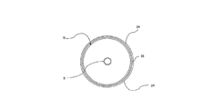
以下、本発明の実施の形態について、図面を参照しながら説明する。図1は、本発明のスパイラル型膜エレメントの一例を示す断面図である。 Hereinafter, embodiments of the present invention will be described with reference to the drawings. FIG. 1 is a cross-sectional view showing an example of a spiral membrane element of the present invention.
本発明のスパイラル型膜エレメントは、外装材の形成方法および構造のみが従来のものと異なっており、他の構造は、上述の従来のスパイラル型膜エレメントの構成をいずれも適用することができる。 The spiral membrane element of the present invention is different from the conventional one only in the method and structure of forming the exterior material, and any of the above-described configurations of the conventional spiral membrane element can be applied to other structures.
従って、本発明のスパイラル型膜エレメントは、図5に示すように、分離膜1、供給側流路材2、および透過側流路材3が積層状態で、有孔の中心管5の周囲にスパイラル状に巻回された円筒状巻回体Rを備えると共に、供給側流体と透過側流体の混合を防ぐための封止部が設けられている。封止部には、例えば、両端封止部11と外周側封止部12が含まれ、また、中心管5の周囲の封止を行う高めに封止部13を形成してもよい。
Therefore, as shown in FIG. 5, the spiral membrane element of the present invention has a
本発明のスパイラル型膜エレメントは、分離膜1と供給側流路材2と透過側流路材3とを積層状態で有孔の中心管5の周囲にスパイラル状に巻回して円筒状巻回体Rを形成する工程と、供給側流体と透過側流体の混合を防ぐための封止部11,12を形成する工程とを含む方法で製造することができる。具体的には、例えば、図6(a)〜(b)に示す工程を実施することにより製造することができる。
The spiral membrane element of the present invention comprises a
図6(a)に示すように、まず、分離膜1を二つ折りにした間に供給側流路材2を配置したものと透過側流路材3とを積み重ね、供給側流体と透過側流体の混合を防ぐ封止部を形成するための接着剤4,6を、透過側流路材3の軸方向両端部および巻回終端部に塗布したユニットを準備する。このとき、分離膜1の折目部分に保護テープを貼り付けても良い。
As shown in FIG. 6A, first, the supply-
分離膜1には、逆浸透膜、限外ろ過膜、精密ろ過膜、ガス分離膜、脱ガス膜などが使用できる。供給側流路材2には、ネット状材料、メッシュ状材料、溝付シート、波形シート等が使用できる。透過側流路材3には、不織布、織布、編布などの繊維布、ネット状材料、メッシュ状材料、溝付シート、波形シート等が使用できる。
As the
有孔の中心管5は、管の周囲に開孔を有するものであれば良く、従来のものが何れも使用できる。一般的には、中心管5はABS樹脂、ポリフェニレンエーテル(PPE)、ポリサルフォン(PSF)等の材質で形成され、その直径は膜エレメントの大きさに応じて異なるが、例えば20〜100mmである。
The
接着剤4,6としては、ウレタン系接着剤、エポキシ系接着剤、ホットメルト接着剤等、従来公知の何れの接着剤も使用することができる。但し、加熱による硬化反応を行う上で、ウレタン系接着剤、エポキシ系接着剤などの熱硬化性樹脂を含有する接着剤が好ましい。 As the adhesives 4 and 6, any conventionally known adhesives such as urethane adhesives, epoxy adhesives, hot melt adhesives and the like can be used. However, an adhesive containing a thermosetting resin such as a urethane-based adhesive or an epoxy-based adhesive is preferable in performing a curing reaction by heating.
次に、図6(b)に示すように、この分離膜ユニットUの複数を積層し、有孔の中心管5の周囲にスパイラル状に巻回した後、接着剤を硬化させるなどして、封止部11,12,13を形成するする。その際、粘着テープをコイル状に巻き付けて、円筒状巻回体Rの形状を保持してもよい。
Next, as shown in FIG. 6 (b), after laminating a plurality of separation membrane units U and winding them around the perforated
分離膜ユニットUを積層する際の数量は、必要とされる透過流量に応じて決まるものであり、1層以上であれば良いが、操作性を考慮すると100層程度が上限である。なお、分離膜ユニットUの長さが長いほど、積層数量は少なくなる。 The number when the separation membrane unit U is stacked is determined according to the required permeation flow rate and may be one or more layers, but about 100 layers is the upper limit in consideration of operability. The longer the separation membrane unit U is, the fewer the number of layers is.
本発明のスパイラル型膜エレメントは、図1に示すように、円筒状巻回体Rの外周側には、繊維巻回物を補強相とする繊維補強樹脂層26が形成されていると共に、その繊維補強樹脂層26の内部又は内側には、その繊維補強樹脂層26の略全長かつ略全周にわたってプラスチック層24が設けられている。本実施形態では、プラスチック層24が筒状の熱収縮フィルムであり、繊維補強樹脂層26とプラスチック層24との間には、繊維布を補強相とする繊維布補強樹脂層25が介在している例を示す。
In the spiral membrane element of the present invention, as shown in FIG. 1, a fiber reinforced
従って、本実施形態のスパイラル型膜エレメントは、円筒状巻回体Rの外周面に筒状の熱収縮フィルムに密着させてプラスチック層24を形成した後、繊維布補強樹脂層25および繊維補強樹脂層26を形成することによって製造することができる。
Therefore, the spiral-type membrane element of this embodiment forms the
熱収縮フィルムは、延伸フィルムの分子配向に基づく内部応力等を利用して、加熱によって収縮が生じるフィルムである。従って、筒状の熱収縮フィルムを円筒状巻回体Rに被せて、適当な加熱手段で加熱を行うことによって、繊維布補強樹脂層25を形成することができる。
The heat-shrinkable film is a film that shrinks by heating using an internal stress or the like based on the molecular orientation of the stretched film. Therefore, the fiber cloth reinforced
熱収縮フィルムとしては、架橋ポリエチレン収縮フィルム、ポリスチレン系収縮フィルム、PET収縮ファイム、塩ビ収縮フィルム、PP収縮ファイム、オレフィン系多層収縮フィルムなどが挙げられる。筒状の熱収縮フィルムは、継ぎ目があるタイプ、継ぎ目がないタイプのどちらでも使用することが可能である。 Examples of the heat shrink film include a crosslinked polyethylene shrink film, a polystyrene shrink film, a PET shrink film, a PVC shrink film, a PP shrink film, and an olefin multilayer shrink film. The tubular heat-shrinkable film can be used for either a type with a seam or a type without a seam.
熱収縮フィルムは、円筒状巻回体Rの外周面に対し、接着せずに密着しているだけでもよいが、接着剤や粘着剤を用いて熱収縮フィルムを接着してもよい。 The heat-shrinkable film may be in close contact with the outer peripheral surface of the cylindrical roll R without being bonded, but the heat-shrinkable film may be bonded using an adhesive or a pressure-sensitive adhesive.
一方、繊維布補強樹脂層25の形成は、例えば、樹脂を含浸又は塗布した繊維布を巻き付けた後に、硬化させることにより行うことができる。繊維布を巻き付けた後に、樹脂を塗布等することも可能である。繊維布の巻き付け回数は、1〜5回が好ましい。
On the other hand, the formation of the fiber cloth reinforced
繊維布補強樹脂層25の補強相(支持体)である繊維布は、例えばPET、PP、PE、PSF、ポリフェニレンスルフィド(PPS)等の樹脂からなる繊維布の他、ガラスクロスなどのガラス繊維布、金属メッシュスクリーンなどの金属繊維布等を使用することも可能である。表示ラベルを内側に設ける場合、その視認性を高める観点から、ガラスクロスなどのガラス繊維布や透明樹脂からなる繊維布を用いるのが好ましい。
The fiber cloth that is the reinforcing phase (support) of the fiber cloth reinforcing
繊維布の種類としては、不織布、織布、編布などが挙げられ、補強効果と視認性の観点から、平織物、あや織物、朱子織物、模しゃ織物、からみ織物、などの織布が好ましい。また1枚の繊維布の厚みは、0.03〜0.6mmが好ましく、0.1〜0.4mmがより好ましい。 Examples of the fiber cloth include non-woven cloth, woven cloth, and knitted cloth. From the viewpoint of reinforcing effect and visibility, woven cloth such as plain woven fabric, twill woven fabric, satin woven fabric, imitation woven fabric, and entwined woven fabric is preferable. . Moreover, 0.03-0.6 mm is preferable and, as for the thickness of one fiber cloth, 0.1-0.4 mm is more preferable.
例えばデザインラベルのように、プラスチック層24に表示等を設ける場合、その外周面に繊維布補強樹脂層25が設けられると、繊維布の開口度が小さいと繊維布裏側のデザィンラベル界面まで樹脂が到達せず、空気層が生じ密着性が低くなるために、デザインラベルの視認性が低下する。このような場合、視認性を満足させるためにはデザインラベル上(繊維布下)において、樹脂層を設けることで密着性を上げることができる。また、開口度が大きいガラスクロス等を使用することで、樹脂が繊維布裏側のデザインラベル界面まで侵入して、密着性を上げることが可能となる。また、繊維布の開口度が大きい場合、樹脂の含浸性が良好になるため、繊維布に樹脂を塗布しなくても、繊維補強樹脂層26を構成する樹脂を移行させて、繊維布に樹脂を含浸させることも可能である。
For example, when a display or the like is provided on the
従って、ガラスクロス等の繊維布の開口度は10%以上のものが好ましいが、開口度が大きくなりすぎると、エレメントの圧縮強度が低下するため、好ましくは20〜40%である。ここで、繊維布の開口度は、繊維布を静置した状態で、顕微鏡観察した際の繊維束同士の間にできる開口の面積の百分率を指す。例えば、開口上部の繊維と、開口右側の繊維と、それら両繊維の重なり部分と、開口との面積を合計した、繰り返し単位の合計面積に対し、その開口の面積の百分率を計算することで、開口度を求めることができる。 Accordingly, the opening degree of the fiber cloth such as glass cloth is preferably 10% or more. However, if the opening degree becomes too large, the compressive strength of the element is lowered, so that the opening degree is preferably 20 to 40%. Here, the opening degree of the fiber cloth refers to a percentage of the area of the opening formed between the fiber bundles when observed with a microscope in a state where the fiber cloth is left still. For example, by calculating the percentage of the area of the opening with respect to the total area of the repeating unit, which is the sum of the areas of the fiber at the top of the opening, the fiber on the right side of the opening, the overlapping portion of both fibers, and the opening, The opening degree can be obtained.
繊維布に塗布等する樹脂は、円筒状巻回体Rの形成時に使用するポリウレタン樹脂またはエポキシ樹脂をそのまま使用できるが、円筒状巻回体Rに使用した樹脂に対して、樹脂の種類を変更することも可能である。ガラス繊維等との組合せで、特に視認性を向上させる樹脂としては、エポキシ樹脂、ポリエステル樹脂、ポリウレタン樹脂が挙げられる。 The resin applied to the fiber cloth can be the polyurethane resin or epoxy resin used when forming the cylindrical wound body R as it is, but the type of resin is changed with respect to the resin used for the cylindrical wound body R. It is also possible to do. Examples of the resin that improves the visibility, particularly in combination with glass fiber, include an epoxy resin, a polyester resin, and a polyurethane resin.
また、繊維巻回物を補強相とする繊維補強樹脂層26の形成は、例えば、樹脂を含浸又は塗布した繊維を、繊維布補強樹脂層25の外周面にらせん状に巻き付けた後に、硬化させることにより行うことができる。繊維補強樹脂層26の厚みは例えば0.5〜4mmであるが、視認性を高める上では、0.5〜2mmが好ましい。
In addition, the fiber reinforced
繊維巻回物を形成する繊維としては、マルチフィランメトやモノフィランメントに、必要に応じて撚りをかけたものや、その集束体を用いることがきるが、繊維補強樹脂用の各種ロービングが好ましく使用できる。また、繊維の種類としては、例えばPET、PP、PE、PSF、ポリフェニレンスルフィド(PPS)、アラミド等の樹脂繊維の他、ガラスなどの無機系繊維、スチールワイヤなどの金属繊維等を使用することも可能である。但し、表示ラベルを内側に設ける場合、その視認性を高める観点から、ガラス繊維や透明樹脂からなる繊維を用いるのが好ましい。 As the fiber forming the fiber wound product, it is possible to use a multifilament or monofilament that is twisted as necessary, or a bundle thereof, but various rovings for fiber reinforced resin are preferably used. it can. In addition, as fiber types, for example, resin fibers such as PET, PP, PE, PSF, polyphenylene sulfide (PPS), and aramid, inorganic fibers such as glass, and metal fibers such as steel wires may be used. Is possible. However, when providing a display label inside, it is preferable to use the fiber which consists of glass fiber or transparent resin from a viewpoint of improving the visibility.
繊維に塗布等する樹脂は、円筒状巻回体Rの形成時に使用するポリウレタン樹脂またはエポキシ樹脂をそのまま使用できるが、円筒状巻回体Rに使用した樹脂に対して、樹脂の種類を変更することも可能である。ガラス繊維との組合せで、特に視認性を向上させる樹脂としては、エポキシ樹脂、ポリエステル樹脂、ポリウレタン樹脂が挙げられる。但し、繊維布補強樹脂層25と繊維補強樹脂層26は、同時に硬化させる方が効率良く、接着性の観点からも、両者の樹脂として、同種の樹脂を使用するのが好ましい。なお、硬化の際の条件は、使用する樹脂や接着剤の種類等に応じて適宜設定される。
As the resin applied to the fiber, the polyurethane resin or epoxy resin used when forming the cylindrical wound body R can be used as it is, but the type of resin is changed with respect to the resin used for the cylindrical wound body R. It is also possible. Examples of the resin that improves the visibility particularly in combination with the glass fiber include an epoxy resin, a polyester resin, and a polyurethane resin. However, it is more efficient to cure the fiber cloth reinforced
分離膜ユニットU(円筒状巻回体R)の樹脂封止と、繊維補強樹脂層26等の樹脂の硬化とは、別々に行ってもよいが、本発明では、分離膜ユニットU(円筒状巻回体R)の樹脂封止と、繊維補強樹脂層26等の樹脂の硬化とを同時に行ってもよい。その場合、両者の樹脂として同種の樹脂を使用するのが好ましい。つまり、加熱による硬化反応を行う上で、ウレタン系接着剤、エポキシ系接着剤などの熱硬化性樹脂を含有する樹脂を使用することが好ましい。
The resin sealing of the separation membrane unit U (cylindrical winding body R) and the curing of the resin such as the fiber reinforced
本発明では、繊維補強樹脂層26の内部又は内側にプラスチック層24が設けられているため、繊維巻回物の巻き付け角度を周方向に対して小さくしても十分な強度が得られるので、当該巻き付け角度が1〜10°の場合でも、十分な強度、耐久性が得られる。
In the present invention, since the
スパイラル型膜エレメントは、樹脂封止後の円筒状巻回体Rを、軸方向の長さを調整するために、両端部のトリミング等を行ってもよい。更に変形(テレスコープ等)を防止するための有孔の端部材や、シール材、補強材などを必要に応じて設けることができる。 The spiral wound membrane element R may be trimmed at both ends in order to adjust the axial length of the cylindrical wound body R after resin sealing. Further, a perforated end member for preventing deformation (such as a telescope), a sealing material, a reinforcing material, and the like can be provided as necessary.
[他の実施形態]
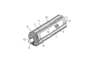
(1)前述の実施形態では、プラスチック層に表示ラベルを設けない例を示したが、本発明では、図3〜4に示すように、プラスチック層24に対して表示ラベル27を別途設けたり、プラスチック層24自身を表示ラベルとして構成してもよい。
[Other Embodiments]
(1) In the above-described embodiment, the example in which the display label is not provided on the plastic layer is shown. However, in the present invention, as shown in FIGS. The
なお、図示した例では、円筒状巻回体Rに粘着テープをコイル状に巻き付けて形状保持層23を形成した後、プラスチック層24を形成している。また、膜エレメントの本体部21の両側には、端部材22a、22bが設けられている。
In the illustrated example, the
表示ラベル27を別途設ける場合、プラスチック層24を形成した後に、表示ラベル27を貼着するのが好ましい。例えば、熱収縮フィルムを用いてプラスチック層24を形成する場合、プラスチック層24に表示ラベルを設けておくと、表示に歪等が生じる場合があるが、後から表示ラベル27を貼着すると、歪の影響を受けずにきれいに表示ラベル27を設けることができる。
When the
プラスチック層24自身を表示ラベルとして構成する場合、これに直接印刷することもできる。印刷は外面及び/又は内面に施される。また、プラスチック層24として、多層タイプのものを用いて中間層に印刷してもよい。更に顔料や染料を含むプラスチック層24を用いることも可能である。印刷することによって表示を大きくし、視野性、表現力を増すことも可能となる。
If the
本発明では、模様、色彩などのデザインは、多少の変形が許されるため、熱収縮フィルム等に設けておき、変形が好ましくない表示等は、別の表示ラベル27として後から貼着するのが最も好ましい。表示ラベル27には、例えば製品会社名、品番、及び装着方向等を表示することができる。
In the present invention, the design such as the pattern and the color is allowed to be slightly deformed. Therefore, the design is provided on a heat shrinkable film or the like, and a display or the like that is not preferable for deformation is pasted as another
表示ラベル27やその機能を有するプラスチック層24が、繊維布補強樹脂層25又は繊維補強樹脂層26(両者を含めてFRPという)を構成する樹脂(例えばエポキシ樹脂)と剥離すると、空気層が発生して、デザインラベルの視認性が低下する。その改善策として、前記のような繊維布の開口度を高める手法以外に、エポキシ樹脂等の樹脂と接着性の良いデザインラベルを用いる方法が挙げられる。
When the
デザインラベルに使用されるインクは、コスト、色合い、印刷の容易さなどを勘案して選択されるが、インクの性状又は配合に関して、エポキシ樹脂等と接着性の高いものを選択する事で、ラベルとFRPが剥離することを防止し、その結果、デザインラベルの視認性低下を防ぐことができる。例えばエポキシ樹脂と接着性の高いインクとして、塩素化ポリプロピレン(PP)系インク、ウレタン系インク、またはワックスを配合していないアクリル(PA)系インクなどを使用することができる。 The ink used for the design label is selected in consideration of cost, color, ease of printing, etc., but the label can be selected by selecting an ink that has high adhesiveness with epoxy resin etc. And FRP can be prevented from peeling off, and as a result, the visibility of the design label can be prevented from being lowered. For example, a chlorinated polypropylene (PP) ink, a urethane ink, or an acrylic (PA) ink that does not contain a wax can be used as an ink having high adhesiveness with an epoxy resin.
また、同様にデザインラベルとFRPが剥離するのを防ぐため、表示ラベル27やその機能を有するプラスチック層24に表面処理を施すことも有効な手段である。表面処理としては、表面にUV処理、コロナ処理又はプラズマ処理を施すことで、エポキシ樹脂との接着性を向上させることができる。エポキシ樹脂とデザインラベルの接着性を評価した結果を図7に示す。
Similarly, in order to prevent the design label and the FRP from peeling off, it is also an effective means to perform a surface treatment on the
デザインラベルのインクを変更した条件、UV処理をした条件では、それぞれ現行品(ポリアミド系インク、表面処理なし)よりも高い接着強度を有しており、ラベルとFRPの剥離から生じる視認性の低下を防ぐことができる。なお、接着力は、FRPとデザインラベルの界面剥離強度を島津製作所製精密万能試験機「オートグラフAG5000B」によって測定し、現行品を1として相対的に評価した。 Under the conditions where the ink of the design label is changed and under the condition of UV treatment, the adhesive strength is higher than that of the current product (polyamide ink, no surface treatment), and the visibility is lowered due to peeling of the label and FRP. Can be prevented. The adhesive strength was relatively evaluated by measuring the interfacial peel strength between the FRP and the design label with a precision universal testing machine “Autograph AG5000B” manufactured by Shimadzu Corporation, and assuming the current product as 1.
(2)前述の実施形態では、プラスチック層が筒状の熱収縮フィルムである例を示したが、本発明では、筒状の熱収縮フィルム以外でプラスチック層を形成してもよく、樹脂シートやフィルムが好ましく使用できる。プラスチック層の厚みは、20〜500μmが好ましい。 (2) In the above-described embodiment, an example in which the plastic layer is a cylindrical heat-shrinkable film has been shown. However, in the present invention, the plastic layer may be formed other than the cylindrical heat-shrinkable film, A film can be preferably used. The thickness of the plastic layer is preferably 20 to 500 μm.
樹脂シート等としては、円筒状巻回体Rとの密着性が良く、追随性のあるものが好ましく、例えば、PP、PE、ポリ塩化ビニル(PVC)、ポリスチレン(PS)、ゴムなどのシート、フィルムなどが挙げられる。このような樹脂シートは、約1周分が巻き込まれるが、粘着剤層を有するものが好ましい。 As a resin sheet etc., the adhesiveness with the cylindrical winding body R is good, and what follows is preferable, for example, sheets of PP, PE, polyvinyl chloride (PVC), polystyrene (PS), rubber, A film etc. are mentioned. Such a resin sheet is wound about one turn, but preferably has a pressure-sensitive adhesive layer.
本発明では、プラスチック層として、光合成のための光を遮蔽するような着色、材料を用いることによって、膜エレメント内部に藻などの植物が発生するのを効果的に防止することができる。 In the present invention, it is possible to effectively prevent the generation of plants such as algae inside the membrane element by using a color or material that shields light for photosynthesis as the plastic layer.
(3)前述の実施形態では、繊維補強樹脂層とプラスチック層との間に繊維布補強樹脂層が介在する例を示したが、本発明では、繊維補強樹脂層の内部又は内側に、その略全長かつ略全周にわたってプラスチック層が設けられていればよく、図2に示すように、繊維巻回物を補強相とする繊維補強樹脂層26がプラスチック層24の表面に設けられていてもよい。
(3) In the above-described embodiment, an example in which the fiber cloth reinforced resin layer is interposed between the fiber reinforced resin layer and the plastic layer has been described. As long as the plastic layer is provided over the entire length and substantially the entire circumference, as shown in FIG. 2, a fiber reinforced
また、プラスチック層24の内側に、繊維布補強樹脂層や繊維補強樹脂層が設けられていてもよい。
Further, a fiber cloth reinforced resin layer or a fiber reinforced resin layer may be provided inside the
以下、本発明の構成と効果を具体的に示す実施例等について説明する。 Examples and the like specifically showing the configuration and effects of the present invention will be described below.
実施例1
まず、日東電工製RO膜ES20と厚み0.7mmのPP製供給側流路材からなる膜リーフユニットを用意した。次いで、直径32mmのPPE製中空状中心管に厚み0.3mmのPET製透過側流路材の先端を固定し、透過側流路材上に膜リーフユニットを封止部に当たる部分でポリウレタン樹脂を塗布しながら積載した。次いで、中空状中心管を軸に回転させテンションを掛けながら積載した膜リーフユニットを巻き込んだ。
Example 1
First, a membrane leaf unit composed of a Nitto Denko RO membrane ES20 and a PP supply-side channel material having a thickness of 0.7 mm was prepared. Next, fix the tip of a permeate side flow path material made of PET with a thickness of 0.3 mm to a hollow center tube made of PPE with a diameter of 32 mm, and apply polyurethane resin at the part where the membrane leaf unit hits the sealing part on the permeate side flow path material It was loaded while applying. Next, the membrane leaf unit loaded while applying tension by rotating the hollow central tube around the shaft was wound.
次いで、粘着テープ(幅75mm)をコイル状に隙間なく巻き付けて形状保持を行い、筒状の熱収縮フィルム(PP樹脂製、厚み50μm、コロナ処理による表面処理品)を被せて120℃で加熱して密着させ、更にその表面に製品名を印刷した表示ラベルを貼着した。 Next, an adhesive tape (width 75 mm) is wound around the coil without any gaps, and the shape is maintained. A cylindrical heat-shrink film (made of PP resin, thickness 50 μm, surface-treated product by corona treatment) is applied and heated at 120 ° C. And a display label printed with the product name was attached to the surface.
次いで、厚み0.3mmのガラスクロス(日東紡績製、平織物、開口度2%)にエポキシ樹脂を一面に含浸し拡がるように塗布して、これを約1周分を巻き込んで、両面テープで端部を固定した。
Next, a 0.3 mm thick glass cloth (Nittobo, plain woven fabric,
これに、エポキシ樹脂を含浸させたガラスロービング(旭ファイバーグラス製)を厚み1mmで巻き付け、樹脂を25℃で硬化させて繊維布補強樹脂層と繊維補強樹脂層とを形成して、スパイラル型膜エレメントを製作した。 A glass roving (manufactured by Asahi Fiber Glass) impregnated with an epoxy resin is wound around this with a thickness of 1 mm, and the resin is cured at 25 ° C. to form a fiber cloth reinforced resin layer and a fiber reinforced resin layer, thereby forming a spiral film Element was made.
得られたスパイラル型膜エレメントは、表示ラベルの製品名がはっきりと認識でき、表示ラベルの上層部分は透明樹脂に近い外観であった。また、繊維補強層は、実際の運転において充分耐え得るだけの強度を示していた。 The obtained spiral membrane element clearly recognized the product name of the display label, and the upper layer portion of the display label had an appearance close to that of a transparent resin. Further, the fiber reinforced layer showed a strength sufficient to withstand in actual operation.
実施例2
実施例1において、ガラスクロスを補強相とする繊維布補強層を設けずに、厚み2mmの繊維補強層を設けたこと以外は、実施例1と全く同じ条件でスパイラル型膜エレメントを製作した。その結果、熱収縮フィルムを設けない従来品に比べて、クラックは生じにくくなっていたが、実施例1に比べて視認性が低下した。
Example 2
In Example 1, a spiral membrane element was produced under exactly the same conditions as in Example 1 except that a fiber reinforcing layer having a thickness of 2 mm was provided without providing a fiber cloth reinforcing layer having a glass cloth as a reinforcing phase. As a result, cracks were less likely to occur as compared to the conventional product not provided with the heat shrink film, but the visibility was reduced as compared with Example 1.
実施例3
実施例1と同様にして表示ラベルの貼着までを行った後、厚み0.15mmのガラスクロス(日東紡績製、平織物、開口度30%)をそのまま約1周分を巻き込んで、両面テープで端部を固定した。これに、エポキシ樹脂を含浸させたガラスロービング(旭ファイバーグラス製)を厚み1.5mmで巻き付け、樹脂を25℃で硬化させて繊維布補強樹脂層と繊維補強樹脂層とを形成して、スパイラル型膜エレメントを製作した。
Example 3
After sticking the display label in the same manner as in Example 1, a glass cloth having a thickness of 0.15 mm (manufactured by Nitto Boseki Co., Ltd., plain woven fabric, opening degree of 30%) is wound around for about one turn, and double-sided tape The end was fixed with. A glass roving (manufactured by Asahi Fiber Glass) impregnated with an epoxy resin is wound around this with a thickness of 1.5 mm, and the resin is cured at 25 ° C. to form a fiber cloth reinforced resin layer and a fiber reinforced resin layer. A mold membrane element was manufactured.
その結果、エポキシ樹脂がガラスクロスの開口部より表示ラベル表面に浸入することで更に視認性が向上し、強度的にも問題のないレベルであった。また、ガラスクロスにエポキシ樹脂を塗布しなくても、ガラスロービングに含浸した樹脂が開口部より浸入して、この樹脂によりガラスクロスが十分含浸された。 As a result, the epoxy resin permeated into the display label surface from the opening of the glass cloth, so that the visibility was further improved and the strength was not a problem. Further, even if the epoxy resin was not applied to the glass cloth, the resin impregnated into the glass roving infiltrated from the opening, and the glass cloth was sufficiently impregnated with this resin.
1 分離膜
2 供給側流路材
3 透過側流路材
4 接着剤
5 中心管
6 接着剤
24 プラスチック層
25 繊維布補強樹脂層
26 繊維補強樹脂層
27 表示ラベル
R 円筒状巻回体
U 分離膜ユニット
DESCRIPTION OF
Claims (5)
前記円筒状巻回体の外周側には、繊維巻回物を補強相とする繊維補強樹脂層が形成されていると共に、その繊維補強樹脂層の内部又は内側には、その繊維補強樹脂層の略全長かつ略全周にわたってプラスチック層が設けられていることを特徴とするスパイラル型膜エレメント。 A separation membrane, a supply-side flow path material, and a permeate-side flow path material are provided with a cylindrical wound body spirally wound around a perforated central tube in a laminated state, and a supply-side fluid and a permeation-side fluid In the spiral membrane element provided with a sealing portion to prevent mixing,
A fiber reinforced resin layer having a fiber wound as a reinforcing phase is formed on the outer peripheral side of the cylindrical wound body, and the fiber reinforced resin layer is formed inside or inside the fiber reinforced resin layer. A spiral membrane element characterized in that a plastic layer is provided over substantially the entire length and substantially the entire circumference.
Priority Applications (1)
| Application Number | Priority Date | Filing Date | Title |
|---|---|---|---|
| JP2007058648A JP2007275871A (en) | 2006-03-13 | 2007-03-08 | Spiral-type film element |
Applications Claiming Priority (2)
| Application Number | Priority Date | Filing Date | Title |
|---|---|---|---|
| JP2006066910 | 2006-03-13 | ||
| JP2007058648A JP2007275871A (en) | 2006-03-13 | 2007-03-08 | Spiral-type film element |
Publications (2)
| Publication Number | Publication Date |
|---|---|
| JP2007275871A true JP2007275871A (en) | 2007-10-25 |
| JP2007275871A5 JP2007275871A5 (en) | 2008-11-27 |
Family
ID=38677922
Family Applications (1)
| Application Number | Title | Priority Date | Filing Date |
|---|---|---|---|
| JP2007058648A Pending JP2007275871A (en) | 2006-03-13 | 2007-03-08 | Spiral-type film element |
Country Status (1)
| Country | Link |
|---|---|
| JP (1) | JP2007275871A (en) |
Cited By (5)
| Publication number | Priority date | Publication date | Assignee | Title |
|---|---|---|---|---|
| JP2009233629A (en) * | 2008-03-28 | 2009-10-15 | Toray Ind Inc | Fluid separation element and its manufacturing method |
| JP2012183527A (en) * | 2011-03-03 | 2012-09-27 | Woongjin Chemical Co Ltd | Tubular formed body for wrapping whole body of membrane module and industrial filter assembly using the same |
| WO2018186109A1 (en) * | 2017-04-07 | 2018-10-11 | 住友化学株式会社 | Spiral-type gas-separation membrane element, gas-separation membrane module, and gas-separation device |
| JP2019051451A (en) * | 2017-09-12 | 2019-04-04 | 旭化成株式会社 | Hollow fiber membrane module, seawater desalination system, seawater desalination method, method for producing fresh water from seawater, operation method of hollow fiber membrane module, filtration method, and production method of hollow fiber membrane module |
| CN111453872A (en) * | 2019-01-18 | 2020-07-28 | 佛山市顺德区美的饮水机制造有限公司 | Composite filter material and manufacturing method thereof, reverse osmosis membrane filter element and water purifier |
-
2007
- 2007-03-08 JP JP2007058648A patent/JP2007275871A/en active Pending
Cited By (9)
| Publication number | Priority date | Publication date | Assignee | Title |
|---|---|---|---|---|
| JP2009233629A (en) * | 2008-03-28 | 2009-10-15 | Toray Ind Inc | Fluid separation element and its manufacturing method |
| JP2012183527A (en) * | 2011-03-03 | 2012-09-27 | Woongjin Chemical Co Ltd | Tubular formed body for wrapping whole body of membrane module and industrial filter assembly using the same |
| WO2018186109A1 (en) * | 2017-04-07 | 2018-10-11 | 住友化学株式会社 | Spiral-type gas-separation membrane element, gas-separation membrane module, and gas-separation device |
| JP2018176040A (en) * | 2017-04-07 | 2018-11-15 | 住友化学株式会社 | Spiral type gas separation membrane element, gas separation membrane module and gas separation device |
| JP7016221B2 (en) | 2017-04-07 | 2022-02-04 | 住友化学株式会社 | Spiral type gas separation membrane element, gas separation membrane module, and gas separation device |
| US11358101B2 (en) | 2017-04-07 | 2022-06-14 | Sumitomo Chemical Company, Limited | Spiral-wound gas separation membrane element, gas separation membrane module, and gas separation apparatus |
| JP2019051451A (en) * | 2017-09-12 | 2019-04-04 | 旭化成株式会社 | Hollow fiber membrane module, seawater desalination system, seawater desalination method, method for producing fresh water from seawater, operation method of hollow fiber membrane module, filtration method, and production method of hollow fiber membrane module |
| JP7197260B2 (en) | 2017-09-12 | 2022-12-27 | 旭化成株式会社 | Hollow fiber membrane module, seawater desalination system, method for desalinating seawater, method for producing freshwater from seawater, method for operating hollow fiber membrane module, method for filtration, and method for manufacturing hollow fiber membrane module |
| CN111453872A (en) * | 2019-01-18 | 2020-07-28 | 佛山市顺德区美的饮水机制造有限公司 | Composite filter material and manufacturing method thereof, reverse osmosis membrane filter element and water purifier |
Similar Documents
| Publication | Publication Date | Title |
|---|---|---|
| WO2007105619A1 (en) | Spiral-type film element | |
| JP5204994B2 (en) | Spiral type membrane element and manufacturing method thereof | |
| KR100990348B1 (en) | Spiral membrane element and process for producing the same | |
| JP2007275871A (en) | Spiral-type film element | |
| US9623379B2 (en) | Spliced fiber-reinforced outer shell for cylindrical filtration element | |
| JP7197260B2 (en) | Hollow fiber membrane module, seawater desalination system, method for desalinating seawater, method for producing freshwater from seawater, method for operating hollow fiber membrane module, method for filtration, and method for manufacturing hollow fiber membrane module | |
| JP5090017B2 (en) | Spiral type membrane element and manufacturing method thereof | |
| JP2006218345A (en) | Spiral type membrane element and its production method | |
| JP4465213B2 (en) | Spiral type membrane element and manufacturing method thereof | |
| JP2009233629A (en) | Fluid separation element and its manufacturing method | |
| NO323046B1 (en) | Membrane element and method of manufacture thereof | |
| JP4485410B2 (en) | Spiral type separation membrane element and manufacturing method thereof | |
| JP2008229453A (en) | Spiral type membrane element and its manufacturing method | |
| US6352641B1 (en) | Wound pocket module | |
| JP4696293B2 (en) | Laminated hose for food | |
| JP2005224718A (en) | Spiral-type membrane element | |
| JP2003275544A (en) | Spiral type membrane element and manufacturing method therefor | |
| JP2004322016A (en) | Spiral type film element and manufacturing method therefor | |
| KR102597942B1 (en) | Filtration method, method of desalinating seawater, method of producing fresh water, hollow fiber membrane module, and seawater desalination system | |
| JP7134046B2 (en) | curved pipe | |
| KR102617616B1 (en) | Separation membrane element and method of use thereof, and water treatment device | |
| JP5044744B2 (en) | Method for manufacturing flexible laminated hose | |
| JP5644393B2 (en) | Method for producing hollow fiber membrane sheet, method for producing hollow fiber membrane module | |
| JP2024011701A (en) | Spiral type membrane element | |
| JPH11226365A (en) | Fluid separation element and manufacture thereof |
Legal Events
| Date | Code | Title | Description |
|---|---|---|---|
| A521 | Written amendment |
Free format text: JAPANESE INTERMEDIATE CODE: A523 Effective date: 20081010 |
|
| RD03 | Notification of appointment of power of attorney |
Effective date: 20081010 Free format text: JAPANESE INTERMEDIATE CODE: A7423 |