JP2004322016A - Spiral type film element and manufacturing method therefor - Google Patents
Spiral type film element and manufacturing method therefor Download PDFInfo
- Publication number
- JP2004322016A JP2004322016A JP2003123485A JP2003123485A JP2004322016A JP 2004322016 A JP2004322016 A JP 2004322016A JP 2003123485 A JP2003123485 A JP 2003123485A JP 2003123485 A JP2003123485 A JP 2003123485A JP 2004322016 A JP2004322016 A JP 2004322016A
- Authority
- JP
- Japan
- Prior art keywords
- sheet
- wound
- flow path
- spiral
- side flow
- Prior art date
- Legal status (The legal status is an assumption and is not a legal conclusion. Google has not performed a legal analysis and makes no representation as to the accuracy of the status listed.)
- Granted
Links
Images


Abstract
Description
【発明の属する技術分野】
本発明は、分離膜、供給側流路材、及び透過側流路材が、透過側流路の軸方向両端部を少なくとも封止した状態で、有孔の中心管にスパイラル状に巻回され、その巻回体の表面に外装材を備えるスパイラル型膜エレメント、及びその製造方法に関する。
【従来の技術】
逆浸透ろ過や限外ろ過、精密ろ過、気体分離、脱ガス等に用いられるスパイラル膜エレメントとして、例えば、供給流体を分離膜表面へ導く供給側流路材、供給流体を分離する分離膜、分離膜を透過し供給流体から分離された透過流体を中心管へと導く透過側流路材からなるユニットを中心管の周りに巻き付けたスパイラル型膜エレメントが知られている。
このようなスパイラル型膜エレメントは、分離膜を二つ折りにした間に供給側流路材を配置したものと透過側流路材とを交互に積み重ね、供給流体と透過流体の混合を防ぐため接着剤を分離膜周辺部に塗布したユニットの単数または複数を中心管の周囲に円筒状に巻回した後、巻回体の外周に巻回体の形状を保持するシートを巻き付けて形成される(例えば、特許文献1参照)。
従来、上記膜エレメントの製造において、巻回体の周りにシートを巻き付ける方法としては、
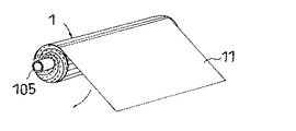
1) 図6に示すように、スパイラル膜エレメント軸方向長さとほぼ同じ幅のシート11を巻き付ける方法、又は
2) 図7に示すように、短冊状の幅の狭いシート12を軸方向の一端から螺旋状に巻き付ける方法が、一般的であった。
【特許文献1】
特許第3035373号公報(第2頁、図2)
【発明が解決しようとする課題】
しかしながら、前者1)の方法では、分離膜周辺部に塗布した接着剤の厚みのため巻回体の軸方向両端のみが太くなっており、軸方向長さと同じ幅のシートを外周に巻き付けると、太くなっている軸方向両端のみに力が集中し、軸方向中央部分には力が掛からない。このため軸方向中央部分では、分離膜と供給側流路材と透過側流路材の密着性が低く、分離膜及び/又は供給側流路材に接着剤が含浸せず、封止機能を発現できない状態、あるいは封止できても供給側流路材が分離膜から浮いた状態であるため、供給側流路材の機能である分離膜近傍の攪拌効果が低下し、分離膜近傍での濃度分極が大きくなるため、スパイラル膜エレメントの性能を低下させる要因となる。また、軸方向中央部分にも力を掛けようとして全体の巻き付け力を高めると、膜シート等にシワが発生するため、この場合もスパイラル膜エレメントの性能を低下させる要因となる。
また、後者2)の方法では、巻回体の一端から巻き始めるため、巻き始め側で表面を締めつける力が大きくなり、ねじれ力によってテレスコープ現象を起こしやすくなる。このため、このねじれ力が一定以下になるようにシートの巻き付ける必要があるが、そうすると軸方向中央部分でも締めつけ力が不十分となり、上記1)と同様に、スパイラル膜エレメントの性能を低下させる要因となる。
そこで、本発明の目的は、巻回体内部で分離膜と供給側流路材と透過側流路材の密着性を高め、かつ、テレスコープ現象の防止と内部でのシワを防止できるスパイラル膜エレメント、及びその製造方法を提供することにある。
【課題を解決するための手段】
上記目的は、下記の如き本発明により達成できる。
即ち、本発明のスパイラル型膜エレメントは、分離膜、供給側流路材、及び透過側流路材が、透過側流路の軸方向両端部を少なくとも封止した状態で、有孔の中心管にスパイラル状に巻回され、その巻回体の表面に外装材を備えるスパイラル型膜エレメントにおいて、前記外装材は、前記巻回体の軸方向中央付近から両端側に広がるように略対称に巻回された単数又は複数のシートであることを特徴とする。
本発明のスパイラル型膜エレメントによれば、外装材であるシートが巻回体の軸方向中央付近から両端側に広がるように略対称に巻回されているため、透過側流路の軸方向両端部の封止部の厚みにより巻回体の軸方向両端のみが太くなっていても、まず軸方向中央部分に力が掛かるので、分離膜と供給側流路材と透過側流路材の密着性を高めることができる。更に、順次外側へ向かってシートが巻回されているため、全ての部位で密着性が高くなり、また、過剰な力をシートに加えることが無いためシワの発生を抑えられる。さらに、中央から対称型にシートを巻いているため、軸方向に対称に力が掛かりテレスコープ現象が起こらない。その結果、スパイラル膜エレメントの性能低下を防ぐことができる。
上記において、前記外装材は、前記巻回体の軸方向中央付近から両端側に向けて、略対称かつらせん状に巻回された偶数枚のシートであるか、あるいは、前記巻回体の軸方向中央付近から両端側に広がる対称な形状のシートであることが好ましい。これらのシートを使用することにより、シートの巻回を行うだけで、中央部分から外側にかけて、両側対称な力を徐々にかけていくことができる。特に前者のシートを用いることにより、テレスコープ現象を抑制しながら、軸方向に均一に適度な締めつけ力を付与することができ、全体の密着性を高める効果をより確実に得られるようになる。また、後者のシートを用いることにより、巻回体の中央側でシートの巻き付け厚みが大きくなるため、巻回体の中央側でより大きな締めつけ力を付与することができる。
また、前記外装材を構成するシートは、粘着剤層を有するものであることが好ましい。その場合、粘着剤層を有するため、シートの巻回を行うだけで、締めつけ力が働いた巻回状態を維持することができる。
一方、本発明のスパイラル型膜エレメントの製造方法は、分離膜、供給側流路材、及び透過側流路材が、透過側流路の軸方向両端部を少なくとも封止した状態で、有孔の中心管にスパイラル状に巻回された巻回体の表面に、シート状の外装材を巻回する工程を含むスパイラル型膜エレメントの製造方法において、前記外装材の巻回工程は、前記巻回体の軸方向中央付近から両端側に広がるように略対称に単数又は複数のシートを巻回することを特徴とする。
本発明の製造方法によると、外装材であるシートを巻回体の軸方向中央付近から両端側に広がるように略対称に巻回するため、透過側流路の軸方向両端部の封止部の厚みにより巻回体の軸方向両端のみが太くなっていても、まず軸方向中央部分に力が掛かるので、分離膜と供給側流路材と透過側流路材の密着性を高めることができる。更に、順次外側へ向かってシートが巻回されているため、全ての部位で密着性が高くなり、また、過剰な力をシートに加えることが無いためシワの発生を抑えられる。さらに、中央から対称型にシートを巻いているため、軸方向に対称に掛かりテレスコープ現象が起こらない。その結果、スパイラル膜エレメントの性能低下を防ぐことができる。
上記において、前記シートを巻回する際のシートにかかる張力が幅1mm当たり2N以下であることが好ましい。このような張力で巻回を行うと、過剰な力が巻回体に加わりにくく、より確実にシワの発生を抑えることができる。
【発明の実施の形態】
以下、本発明の実施の形態について、図面を参照しながら説明する。図1〜図3は、本発明のスパイラル型膜エレメントの製造方法の一例を示す工程図である。まず、本発明における巻回体1について説明する。
本発明における巻回体1は、図1〜図3に示すように、分離膜101、供給側流路材102、及び透過側流路材103が、透過側流路の軸方向両端部を少なくとも封止した状態で、有孔の中心管105にスパイラル状に巻回されたものである。本発明における巻回体1は、従来のエレメントに使用されるものと特に変わりがなく、従来公知のものを何れも使用することができる。例えば、透過側流路の軸方向両端部の封止には、接着剤、ホットメルト接着剤、熱融着型粘着テープ、熱融着性シートなどを用いることができる。
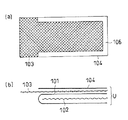
上記の巻回体1は、例えば図1〜図2に示す工程により製造することができる。まず、図1に示すように、分離膜101を二つ折りにした間に供給側流路材102を配置したものと透過側流路材103とを積み重ね、供給流体と透過流体の混合を防ぐ封止部を形成するための接着剤104,106を、透過側流路材103の軸方向両端部及び巻回終端部に塗布した分離膜ユニットUを準備する。
本実施形態では、供給側流路材102を挟みこむように二つ折りにした分離膜101の上に、透過側流路材103を重ねて、接着剤104,106を塗布する例で説明したが、透過側流路材103の上に二つ折りにした分離膜101を重ねその上に接着剤104,106を塗布することも可能である。また、二つ折りにした分離膜101の代わりに、交互に折り返した連続膜を使用したり、分離膜101の折り部分が巻回終端側になるように配置してもよい。
分離膜101には、逆浸透膜、限外ろ過膜、精密ろ過膜、ガス分離膜、脱ガス膜などが使用できる。供給側流路材102にはネット状材料等が使用できる。透過側流路材103にはネット状、編み物状材料等が使用できる。接着剤104,106にはウレタン、エポキシ等が使用できる。
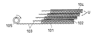
次に、図2に示すように、この分離膜ユニットUの単数または複数を、有孔の中心管105の周囲にスパイラル状に巻回した後、接着剤104,106を熱等により硬化させることで、透過側流路の軸方向両端部が少なくとも封止された巻回体1を得る。本実施形態では、その際に透過側流路の巻回終端部や中心管105の周囲部も封止される。
分離膜ユニットUを積層する際の数量は、必要とされる透過流量に応じて決まるものであり、1層以上であればよいが、操作性を考慮すると100層程度が上限である。
本発明のスパイラル型膜エレメントは、上記のような巻回体1の表面に設けられた外装材が、巻回体1の軸方向中央付近から両端側に広がるように略対称に巻回された単数又は複数のシートであることを特徴とする。このような外装材の巻回工程は、巻回体1の軸方向中央付近から両端側に広がるように略対称に単数又は複数のシートを巻回することで行うことができる。その際、シートの巻回方向は、巻回体1における分離膜ユニットUの巻回方向と同じになる。
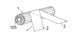
本発明において、略対称にシートを巻回するとは、一枚の左右略対称型のシートを用いるか、あるいは複数枚のシートを左右略対称に配置して螺旋状に巻き付ける意味である。本実施形態では、図3に示すように、外装材が巻回体1の軸方向中央付近から両端側に向けて、略対称かつらせん状に巻回された偶数枚のシート2である例を示す。
本発明において、巻回体1の軸方向中央付近の位置としては、軸方向中央を中心にして、巻回体1の軸方向長さの20%の範囲内が好ましい。この範囲内にシートの巻回の開始位置が配置される。なお、巻回の開始位置において、偶数枚のシート2は連結されていてもよく、1枚のシートを開始位置で2つ折りにした2枚のシートを巻回してもよい。
本発明において、シートを巻回する際のシートにかかる張力は、巻回体1とシートとの接触部分の幅1mm当たり2N以下であることが好ましく、幅1mm当たり0.05〜1Nがより好ましい。例えば、シート全体にかかる張力を、シートの巻回幅に応じて変化させることにより、シート幅が変化するシートを巻回する場合でも上記張力を所望の値にすることができる。
本発明で巻き付けるシートは、シート巻付時張力での伸びが10%以下が好ましく、巻回体1の外周面に沿って巻き付け可能な柔軟性があれば良く、材質・形状で規定されるものではない。このため数種のシートがラミネートされていたり、繊維補強されていたり、あるいはシート内側に粘着層が形成されているような多層構造のシートであっても、上記条件を満たすものであれば使用できる。但し、好ましいシート基材として、ポリエステル、ポリプロピレン、ポリエチレン、ポリ塩化ビニル、ガラス繊維布等が使用できる。
図3に示す実施形態のように、複数枚のシート2を左右対称に配置して螺旋状に巻き付ける場合、螺旋状のシート同士が重なって隙間が無い状態とするのが好ましい。具体的にはシート2の重なりをシート幅の5〜50%とするのが好ましい。この範囲を下回ると隙間が出来やすく、隙間が出来るとその部分は分離膜と供給側流路材と透過側流路材の密着性が低下し易い。また、この範囲を超えるとシート2の巻き付け時間とシート2の使用量が増加し安価なスパイラル膜エレメントを供給しにくくなる。なお、シート2の幅は、20〜200mmが好ましいが、シート2の幅は長手方向で変化していてもよい。
本実施形態では、短冊状のシート2の先端を2枚とも巻回体1の軸方向長さ中心に固定する。固定の方法は貼付、融着、接着などの方法で行うことができる。各々のシート2を巻回体1の中心を鏡面とした対称型で巻回体1に螺旋状に巻き付ていく。その際、シート2間に隙間が空かないように巻回体1の両端まで巻き付け、スパイラル膜エレメントを得る。図示した例では、シート2が2枚の例で説明したが、対称型でシートを巻き付けできる4枚、8枚等の偶数枚で実施しても良い。
本発明のスパイラル膜エレメントには、更に変形(テレスコープ等)を防止するための有孔の端部材や、シール材、補強材などを必要に応じて設けることができる。
[他の実施形態]
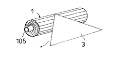
(1)前述の実施形態では、巻回体の軸方向中央付近から両端側に向けて、偶数枚のシートが略対称かつらせん状に巻回された例を示したが、本発明では、図4に示すように、外装材が、巻回体1の軸方向中央付近から両端側に広がる対称な形状のシート3であってもよい。
この実施形態では、例えば底辺の長さが巻回体1の軸方向長さに略等しい2等辺三角形状のシート3が使用できる。シート3の2等辺三角形の頂点を巻回体1の軸方向長さ中心に固定する。固定の方法は貼付、融着、接着などの方法で行うことができ、シート3を巻回体に巻き付け、スパイラル膜エレメントを得る。
(2)本発明では、図3〜図4に示すものに限らず、例えば図5に示すシートを使用することができる。図5(a)に示すように、対称型のシート3は、台形状でもよく、図5(b)に示すように、対称型のシート3は、五角形状でもよい。これらの斜辺部分は直線でなくてもよい。また、図5(c)に示すように、短冊状のシート2は、2枚が重ならないように周方向に切断したものでもよく、巻回の終端側も同様に周方向に切断していてもよい。
【図面の簡単な説明】
【図1】本発明のスパイラル型膜エレメントの製造方法の一例を示す工程図であり、(a)は平面図、(b)は正面図
【図2】本発明のスパイラル型膜エレメントの製造方法の一例を示す工程図
【図3】本発明のスパイラル型膜エレメントの製造方法の一例を示す工程図
【図4】本発明のスパイラル型膜エレメントの製造方法の他の例を示す工程図
【図5】本発明のスパイラル型膜エレメントの製造方法に使用するシートの他の例を示す平面図
【図6】従来のスパイラル型膜エレメントの製造方法を示す工程図
【図7】従来のスパイラル型膜エレメントの製造方法を示す工程図
【符号の説明】
1 巻回体
2 シート
3 シート
101 分離膜
102 供給側流路材
103 透過側流路材
105 中心管
U 分離膜ユニットTECHNICAL FIELD OF THE INVENTION
In the present invention, the separation membrane, the supply-side flow path material, and the permeation-side flow path material are spirally wound around a perforated center tube with at least both ends in the axial direction of the permeation-side flow path sealed. The present invention relates to a spiral-type membrane element provided with an exterior material on the surface of a wound body thereof, and a method for producing the spiral-type membrane element.
[Prior art]
As a spiral membrane element used for reverse osmosis filtration, ultrafiltration, microfiltration, gas separation, degassing, etc., for example, a supply-side channel material that guides the supply fluid to the separation membrane surface, a separation membrane that separates the supply fluid, separation A spiral-type membrane element is known in which a unit made of a permeate-side flow path material that permeates a membrane and separates a supply fluid from a supply fluid to a central pipe is wound around the central pipe.
Such a spiral type membrane element has a structure in which the supply-side flow path material is disposed while the separation membrane is folded in two, and the permeation-side flow path material is alternately stacked, and is bonded to prevent mixing of the supply fluid and the permeation fluid. One or more of the units in which the agent is applied to the periphery of the separation membrane are wound in a cylindrical shape around the central tube, and then a sheet holding the shape of the wound body is wound around the outer periphery of the wound body ( For example, see Patent Document 1).
Conventionally, in the production of the membrane element, as a method of winding a sheet around a wound body,
1) A method of winding a
[Patent Document 1]
Japanese Patent No. 3035373 (
[Problems to be solved by the invention]
However, in the former method 1), only the both ends in the axial direction of the wound body are thick due to the thickness of the adhesive applied to the periphery of the separation membrane, and when a sheet having the same width as the axial length is wound around the outer periphery, The force is concentrated only on the thicker ends in the axial direction, and no force is applied on the central portion in the axial direction. For this reason, in the central portion in the axial direction, the adhesion between the separation membrane, the supply-side flow path material, and the permeation-side flow path material is low, and the separation membrane and / or the supply-side flow path material are not impregnated with the adhesive, and have a sealing function. Since the supply-side flow path material is floating from the separation membrane even if it cannot be expressed or can be sealed, the stirring effect near the separation membrane, which is a function of the supply-side flow path material, is reduced, and in the vicinity of the separation membrane, Since the concentration polarization becomes large, it becomes a factor of deteriorating the performance of the spiral membrane element. In addition, if the overall wrapping force is increased to apply a force to the central portion in the axial direction, wrinkles are generated in the membrane sheet and the like, and in this case, the performance of the spiral membrane element is also reduced.
In the latter method 2), since the winding is started from one end of the wound body, the force for tightening the surface at the winding start side is increased, and the torsion force tends to cause a telescopic phenomenon. For this reason, it is necessary to wind the sheet so that the torsional force is equal to or less than a certain value. However, in this case, the tightening force becomes insufficient even in the central portion in the axial direction, and as in 1), the performance of the spiral membrane element is reduced. It becomes.
Therefore, an object of the present invention is to increase the adhesion between the separation membrane, the supply-side flow path material, and the permeation-side flow path material inside the wound body, and to prevent a telescopic phenomenon and a wrinkle inside the spiral membrane. An object of the present invention is to provide an element and a method of manufacturing the element.
[Means for Solving the Problems]
The above object can be achieved by the present invention as described below.
That is, the spiral-type membrane element of the present invention has a perforated central pipe in which the separation membrane, the supply-side flow path material, and the permeation-side flow path material seal at least both axial ends of the permeation-side flow path. In a spiral type membrane element wound spirally and provided with an exterior material on the surface of the wound body, the exterior material is wound substantially symmetrically so as to spread from near the axial center of the wound body to both end sides. It is characterized in that it is a turned single or plural sheets.
According to the spiral membrane element of the present invention, since the sheet as the exterior material is wound substantially symmetrically so as to spread from the vicinity of the center in the axial direction of the winding body to both end sides, both ends in the axial direction of the permeation-side flow path Even if only the two ends in the axial direction of the wound body are thickened due to the thickness of the sealing part, the force is first applied to the central part in the axial direction, so that the separation membrane, the supply-side flow path material, and the permeation-side flow path material Can be enhanced. Further, since the sheet is sequentially wound outward, the adhesiveness is improved at all portions, and the generation of wrinkles can be suppressed because excessive force is not applied to the sheet. Further, since the sheet is wound symmetrically from the center, a force is applied symmetrically in the axial direction, and the telescope phenomenon does not occur. As a result, the performance of the spiral membrane element can be prevented from deteriorating.
In the above, the exterior material is an even number of sheets wound substantially symmetrically and spirally from near the center in the axial direction of the wound body toward both ends, or the axis of the wound body. It is preferable that the sheet has a symmetrical shape that spreads from both sides near the center in the direction. By using these sheets, it is possible to gradually apply a bilaterally symmetrical force from the central portion to the outside only by winding the sheet. In particular, by using the former sheet, an appropriate tightening force can be uniformly applied in the axial direction while suppressing the telescopic phenomenon, and the effect of increasing the overall adhesion can be more reliably obtained. In addition, by using the latter sheet, the winding thickness of the sheet is increased at the center of the wound body, so that a greater tightening force can be applied at the center of the wound body.
Further, it is preferable that the sheet constituting the exterior material has an adhesive layer. In this case, since the sheet has the pressure-sensitive adhesive layer, it is possible to maintain the wound state in which the tightening force has been applied only by winding the sheet.
On the other hand, the method for producing a spiral-wound membrane element of the present invention is characterized in that the separation membrane, the supply-side flow path material, and the permeation-side flow path material are perforated while at least the axial ends of the permeation-side flow path are sealed. In a method of manufacturing a spiral-type membrane element including a step of winding a sheet-like exterior material on a surface of a spirally wound body wound around a center tube of the above, the step of winding the exterior material includes the step of: It is characterized in that one or more sheets are wound substantially symmetrically so as to spread from near the center in the axial direction of the rotator to both ends.
According to the production method of the present invention, since the sheet as the exterior material is wound substantially symmetrically so as to spread from the vicinity of the center in the axial direction of the wound body to both ends, the sealing portions at both ends in the axial direction of the permeation-side flow path. Even when only the two ends in the axial direction of the wound body are thickened due to the thickness of the wound body, the force is first applied to the central part in the axial direction, so that the adhesion between the separation membrane, the supply-side flow path material, and the permeation-side flow path material can be improved. it can. Further, since the sheet is sequentially wound outward, the adhesiveness is improved at all portions, and the generation of wrinkles can be suppressed because excessive force is not applied to the sheet. Further, since the sheet is wound symmetrically from the center, the sheet is symmetrical in the axial direction and the telescope phenomenon does not occur. As a result, the performance of the spiral membrane element can be prevented from deteriorating.
In the above, it is preferable that the tension applied to the sheet when winding the sheet is 2 N or less per 1 mm in width. When winding is performed with such tension, an excessive force is less likely to be applied to the wound body, and wrinkles can be more reliably suppressed.
BEST MODE FOR CARRYING OUT THE INVENTION
Hereinafter, embodiments of the present invention will be described with reference to the drawings. 1 to 3 are process diagrams illustrating an example of a method for manufacturing a spiral-type membrane element of the present invention. First, the
As shown in FIGS. 1 to 3, the
The above-mentioned
In the present embodiment, an example has been described in which the permeate-side
As the
Next, as shown in FIG. 2, one or more of the separation membrane units U are spirally wound around a perforated
The number of lamination of the separation membrane units U is determined according to the required permeation flow rate, and may be one or more, but the upper limit is about 100 in consideration of operability.
The spiral-wound membrane element of the present invention is wound substantially symmetrically so that the exterior material provided on the surface of the
In the present invention, to wind a sheet substantially symmetrically means to use a single left-right substantially symmetrical sheet, or to arrange a plurality of sheets substantially symmetrically left and right and wind it spirally. In the present embodiment, as shown in FIG. 3, an example in which the exterior material is an even number of
In the present invention, the position near the axial center of the
In the present invention, the tension applied to the sheet when the sheet is wound is preferably 2 N or less per 1 mm width of the contact portion between the
The sheet to be wound in the present invention preferably has an elongation of 10% or less in tension at the time of winding the sheet, as long as the sheet has flexibility so that it can be wound along the outer peripheral surface of the
When a plurality of
In the present embodiment, both ends of the strip-shaped
The spiral membrane element of the present invention may be provided with a perforated end member for further preventing deformation (telescope or the like), a sealing material, a reinforcing material, and the like, if necessary.
[Other embodiments]
(1) In the above-described embodiment, an example is shown in which an even number of sheets are wound substantially symmetrically and spirally from the vicinity of the center in the axial direction of the wound body to both end sides. As shown in FIG. 4, the exterior material may be a
In this embodiment, for example, an isosceles
(2) In the present invention, for example, the sheet shown in FIG. 5 can be used without being limited to those shown in FIGS. As shown in FIG. 5A, the
[Brief description of the drawings]
BRIEF DESCRIPTION OF THE DRAWINGS FIG. 1 is a process chart showing an example of a method for producing a spiral membrane element of the present invention, wherein (a) is a plan view and (b) is a front view. FIG. 3 is a process diagram showing an example of a method for manufacturing a spiral membrane element of the present invention. FIG. 4 is a process diagram showing another example of a method for manufacturing a spiral membrane element of the present invention. 5 is a plan view showing another example of a sheet used in the method for manufacturing a spiral-type membrane element of the present invention. FIG. 6 is a process chart showing a conventional method for manufacturing a spiral-type membrane element. FIG. 7 is a conventional spiral-type membrane. Process drawing showing element manufacturing method [Explanation of symbols]
DESCRIPTION OF
Claims (6)
前記外装材は、前記巻回体の軸方向中央付近から両端側に広がるように略対称に巻回された単数又は複数のシートであることを特徴とするスパイラル型膜エレメント。The separation membrane, the supply-side flow path material, and the permeation-side flow path material are spirally wound around a perforated central tube with at least the axial ends of the permeation-side flow path sealed. In a spiral type membrane element having an exterior material on the surface of the body,
The spiral-type membrane element, wherein the exterior material is a single or a plurality of sheets wound substantially symmetrically so as to spread from near an axial center of the wound body to both end sides.
前記外装材の巻回工程は、前記巻回体の軸方向中央付近から両端側に広がるように略対称に単数又は複数のシートを巻回することを特徴とするスパイラル型膜エレメントの製造方法。A wound body in which the separation membrane, the supply-side flow path material, and the permeation-side flow path material are spirally wound around a perforated central tube with at least both ends in the axial direction of the permeation-side flow path sealed. In the method of manufacturing a spiral-type membrane element including a step of winding a sheet-like exterior material on the surface of,
The method of manufacturing a spiral-wound membrane element, wherein the step of winding the exterior member winds a single or a plurality of sheets substantially symmetrically so as to spread from near an axial center of the wound body to both end sides.
Priority Applications (1)
| Application Number | Priority Date | Filing Date | Title |
|---|---|---|---|
| JP2003123485A JP4289603B2 (en) | 2003-04-28 | 2003-04-28 | Spiral type membrane element and manufacturing method thereof |
Applications Claiming Priority (1)
| Application Number | Priority Date | Filing Date | Title |
|---|---|---|---|
| JP2003123485A JP4289603B2 (en) | 2003-04-28 | 2003-04-28 | Spiral type membrane element and manufacturing method thereof |
Publications (2)
| Publication Number | Publication Date |
|---|---|
| JP2004322016A true JP2004322016A (en) | 2004-11-18 |
| JP4289603B2 JP4289603B2 (en) | 2009-07-01 |
Family
ID=33501359
Family Applications (1)
| Application Number | Title | Priority Date | Filing Date |
|---|---|---|---|
| JP2003123485A Expired - Fee Related JP4289603B2 (en) | 2003-04-28 | 2003-04-28 | Spiral type membrane element and manufacturing method thereof |
Country Status (1)
| Country | Link |
|---|---|
| JP (1) | JP4289603B2 (en) |
Cited By (4)
| Publication number | Priority date | Publication date | Assignee | Title |
|---|---|---|---|---|
| JP2007196130A (en) * | 2006-01-26 | 2007-08-09 | Asahi Kasei Chemicals Corp | Box pleat element and its manufacturing method |
| WO2008035714A1 (en) * | 2006-09-22 | 2008-03-27 | Nitto Denko Corporation | Gas removal device |
| JP2008073640A (en) * | 2006-09-22 | 2008-04-03 | Nitto Denko Corp | Deaeration device |
| JP2008073641A (en) * | 2006-09-22 | 2008-04-03 | Nitto Denko Corp | Deaeration device |
Families Citing this family (1)
| Publication number | Priority date | Publication date | Assignee | Title |
|---|---|---|---|---|
| CN108744986A (en) * | 2018-07-20 | 2018-11-06 | 芜湖新瑟安智能科技有限公司 | A kind of wound membrane element |
-
2003
- 2003-04-28 JP JP2003123485A patent/JP4289603B2/en not_active Expired - Fee Related
Cited By (8)
| Publication number | Priority date | Publication date | Assignee | Title |
|---|---|---|---|---|
| JP2007196130A (en) * | 2006-01-26 | 2007-08-09 | Asahi Kasei Chemicals Corp | Box pleat element and its manufacturing method |
| WO2008035714A1 (en) * | 2006-09-22 | 2008-03-27 | Nitto Denko Corporation | Gas removal device |
| JP2008073640A (en) * | 2006-09-22 | 2008-04-03 | Nitto Denko Corp | Deaeration device |
| JP2008073641A (en) * | 2006-09-22 | 2008-04-03 | Nitto Denko Corp | Deaeration device |
| US20090301306A1 (en) * | 2006-09-22 | 2009-12-10 | Nitto Denko Corporation | Gas removal device |
| KR101128592B1 (en) * | 2006-09-22 | 2012-03-23 | 닛토덴코 가부시키가이샤 | Gas removal device |
| US8177889B2 (en) | 2006-09-22 | 2012-05-15 | Nitto Denko Corporation | Gas removal device |
| TWI391174B (en) * | 2006-09-22 | 2013-04-01 | Nitto Denko Corp | Degassing device |
Also Published As
| Publication number | Publication date |
|---|---|
| JP4289603B2 (en) | 2009-07-01 |
Similar Documents
| Publication | Publication Date | Title |
|---|---|---|
| JP5763662B2 (en) | Method of applying a tape layer to the outer periphery of a spiral wound module | |
| US8991027B2 (en) | Spiral wound filtration module | |
| US8668828B2 (en) | Sanitary spiral wound filtration cartridge | |
| EP2376214A1 (en) | Membrane leaf packet with reinforced fold | |
| CN102470324B (en) | Spiral wound module including membrane sheet with capillary channels | |
| JP2005103516A (en) | Spiral type membrane element and its production method | |
| JPH10137558A (en) | Spiral separation membrane element and its production | |
| JP2004202382A (en) | Manufacturing method for spiral type membrane element | |
| JP2009195871A (en) | Spiral membane element | |
| JP4289603B2 (en) | Spiral type membrane element and manufacturing method thereof | |
| JP2006218345A (en) | Spiral type membrane element and its production method | |
| JP4465213B2 (en) | Spiral type membrane element and manufacturing method thereof | |
| JP2004202371A (en) | Method for manufacturing spiral type membrane element | |
| US20020070158A1 (en) | Membrane element and process for its production | |
| JP5090017B2 (en) | Spiral type membrane element and manufacturing method thereof | |
| JP2003275545A (en) | Spiral type membrane element and manufacturing method therefor | |
| JP2006136839A (en) | Spiral membrane element | |
| JP2000342939A (en) | Production of spiral membrane module | |
| JP2006326376A (en) | Spiral type separation membrane element and its production method | |
| JP2003275544A (en) | Spiral type membrane element and manufacturing method therefor | |
| JP2017080709A (en) | Separation membrane element | |
| JP2005224718A (en) | Spiral-type membrane element | |
| JPH04326926A (en) | Spiral type separation membrane element and production thereof | |
| JP2005211790A (en) | Spiral membrane element and reverse flow washing method | |
| JP2001198442A (en) | Fluid separation element, production method for the same, and fluid separation membrane module |
Legal Events
| Date | Code | Title | Description |
|---|---|---|---|
| A621 | Written request for application examination |
Free format text: JAPANESE INTERMEDIATE CODE: A621 Effective date: 20051114 |
|
| A977 | Report on retrieval |
Free format text: JAPANESE INTERMEDIATE CODE: A971007 Effective date: 20070903 |
|
| A131 | Notification of reasons for refusal |
Free format text: JAPANESE INTERMEDIATE CODE: A131 Effective date: 20081021 |
|
| A521 | Written amendment |
Free format text: JAPANESE INTERMEDIATE CODE: A523 Effective date: 20081216 |
|
| RD03 | Notification of appointment of power of attorney |
Free format text: JAPANESE INTERMEDIATE CODE: A7423 Effective date: 20081216 |
|
| TRDD | Decision of grant or rejection written | ||
| A01 | Written decision to grant a patent or to grant a registration (utility model) |
Free format text: JAPANESE INTERMEDIATE CODE: A01 Effective date: 20090326 |
|
| A01 | Written decision to grant a patent or to grant a registration (utility model) |
Free format text: JAPANESE INTERMEDIATE CODE: A01 |
|
| A61 | First payment of annual fees (during grant procedure) |
Free format text: JAPANESE INTERMEDIATE CODE: A61 Effective date: 20090327 |
|
| R150 | Certificate of patent or registration of utility model |
Free format text: JAPANESE INTERMEDIATE CODE: R150 |
|
| FPAY | Renewal fee payment (event date is renewal date of database) |
Free format text: PAYMENT UNTIL: 20120410 Year of fee payment: 3 |
|
| FPAY | Renewal fee payment (event date is renewal date of database) |
Free format text: PAYMENT UNTIL: 20120410 Year of fee payment: 3 |
|
| FPAY | Renewal fee payment (event date is renewal date of database) |
Free format text: PAYMENT UNTIL: 20150410 Year of fee payment: 6 |
|
| R250 | Receipt of annual fees |
Free format text: JAPANESE INTERMEDIATE CODE: R250 |
|
| LAPS | Cancellation because of no payment of annual fees |