JP2007268448A - Ultrasonic washing device - Google Patents
Ultrasonic washing device Download PDFInfo
- Publication number
- JP2007268448A JP2007268448A JP2006098459A JP2006098459A JP2007268448A JP 2007268448 A JP2007268448 A JP 2007268448A JP 2006098459 A JP2006098459 A JP 2006098459A JP 2006098459 A JP2006098459 A JP 2006098459A JP 2007268448 A JP2007268448 A JP 2007268448A
- Authority
- JP
- Japan
- Prior art keywords
- ultrasonic
- cleaning
- vibration
- plate
- vibrating
- Prior art date
- Legal status (The legal status is an assumption and is not a legal conclusion. Google has not performed a legal analysis and makes no representation as to the accuracy of the status listed.)
- Granted
Links
- 238000005406 washing Methods 0.000 title abstract description 11
- 239000007788 liquid Substances 0.000 claims abstract description 36
- 230000005855 radiation Effects 0.000 claims abstract description 9
- 239000002131 composite material Substances 0.000 claims abstract description 6
- 238000005498 polishing Methods 0.000 claims abstract description 3
- 230000001902 propagating effect Effects 0.000 claims abstract description 3
- 238000004140 cleaning Methods 0.000 claims description 79
- 238000004506 ultrasonic cleaning Methods 0.000 claims description 31
- XLYOFNOQVPJJNP-UHFFFAOYSA-N water Substances O XLYOFNOQVPJJNP-UHFFFAOYSA-N 0.000 claims description 14
- 239000000463 material Substances 0.000 abstract description 3
- 238000005259 measurement Methods 0.000 description 17
- 239000010453 quartz Substances 0.000 description 15
- VYPSYNLAJGMNEJ-UHFFFAOYSA-N silicon dioxide Inorganic materials O=[Si]=O VYPSYNLAJGMNEJ-UHFFFAOYSA-N 0.000 description 15
- 239000004065 semiconductor Substances 0.000 description 13
- 238000002834 transmittance Methods 0.000 description 13
- 235000012431 wafers Nutrition 0.000 description 12
- 238000002347 injection Methods 0.000 description 7
- 239000007924 injection Substances 0.000 description 7
- 229910001220 stainless steel Inorganic materials 0.000 description 6
- 239000010935 stainless steel Substances 0.000 description 6
- 239000011521 glass Substances 0.000 description 5
- 230000005284 excitation Effects 0.000 description 4
- 239000004973 liquid crystal related substance Substances 0.000 description 3
- 238000003754 machining Methods 0.000 description 3
- 238000004519 manufacturing process Methods 0.000 description 3
- 230000001143 conditioned effect Effects 0.000 description 2
- 239000000428 dust Substances 0.000 description 2
- 230000000694 effects Effects 0.000 description 2
- 238000005516 engineering process Methods 0.000 description 2
- 239000000758 substrate Substances 0.000 description 2
- 239000000853 adhesive Substances 0.000 description 1
- 230000001070 adhesive effect Effects 0.000 description 1
- 238000004364 calculation method Methods 0.000 description 1
- 239000000919 ceramic Substances 0.000 description 1
- 239000010419 fine particle Substances 0.000 description 1
- 238000000034 method Methods 0.000 description 1
- 239000002245 particle Substances 0.000 description 1
- 238000002791 soaking Methods 0.000 description 1
- 239000000243 solution Substances 0.000 description 1
- 230000002195 synergetic effect Effects 0.000 description 1
Images

Abstract
Description
本発明は、半導体ウエハー、ガラスマスク、液晶ガラス基板、ハードディスク盤などの超音波振動による洗浄に関する。 The present invention relates to cleaning of semiconductor wafers, glass masks, liquid crystal glass substrates, hard disk boards and the like by ultrasonic vibration.
半導体ウエハー、液晶用のガラス、ハードディスク盤等の微細加工品の精密洗浄には、高周波の超音波洗浄装置が用いられている。精密洗浄の対象とする汚れは、1μm以下の付着粒子等であり、洗浄槽内に満たされた洗浄液中を伝わる超音波振動、又は、洗浄液と超音波振動との相乗効果により、汚れを剥離させるものである。
従来、超音波洗浄装置では、超音波振動を発生させる超音波振動素子の材質として、圧電セラミック等が用いられている。更に、超音波振動素子が発する超音波振動を洗浄装置内の洗浄液に伝達させる振動板の材質として、一般に市販されているステンレス板を用いる場合が多い。
この振動板は洗浄する対象物である被洗浄物の大きさに合わせて作られ、適当な大きさの超音波振動素子を複数枚組み合わせて、これらを振動板に貼り合わせている。
振動板の振動により、洗浄液が振動して、従来の被洗浄物に対しては、満遍なく超音波振動が照射されるように構成されていた。
例として、超音波振動素子とステンレス製の振動板との共振周波数が1MHz程度の超音波洗浄装置であれば、振動板の板厚が0.01mm変化すると、共振周波数が3KHz程度変化することが知られている。このような共振周波数のばらつきが洗浄面に対して洗浄強度のばらつきを生じさせる原因となっていることが分かっている。
従来の市販のステンレス板の購入状態で用いたとき、板厚公差が実質±7.5%程度あるので共振周波数は、±150KHz程度のばらつきが生じることがある。
ところが、年々、半導体ウエハーに代表されるように、被洗浄物の大きさが大きくなる上、回路パターンは微細化が進み高密度回路が形成されるようになり、半導体の製造過程に組み入れられる洗浄装置にもますます洗浄むらを発生させない均一な高精密の洗浄が行える洗浄装置が求められるようになってきた。
High-frequency ultrasonic cleaning devices are used for precision cleaning of finely processed products such as semiconductor wafers, liquid crystal glass, and hard disk boards. The dirt that is subject to precision cleaning is adhered particles of 1 μm or less, and the dirt is peeled off by the ultrasonic vibration transmitted through the cleaning liquid filled in the cleaning tank or by the synergistic effect of the cleaning liquid and the ultrasonic vibration. Is.
Conventionally, in an ultrasonic cleaning apparatus, a piezoelectric ceramic or the like is used as a material of an ultrasonic vibration element that generates ultrasonic vibration. Further, a commercially available stainless steel plate is often used as a material for the vibration plate that transmits ultrasonic vibration generated by the ultrasonic vibration element to the cleaning liquid in the cleaning apparatus.
This diaphragm is made according to the size of an object to be cleaned, which is an object to be cleaned, and a plurality of ultrasonic vibration elements of appropriate sizes are combined and bonded to the diaphragm.
The cleaning liquid vibrates due to the vibration of the diaphragm, and ultrasonic vibrations are uniformly applied to the conventional object to be cleaned.
As an example, if the ultrasonic cleaning device has a resonance frequency of about 1 MHz between the ultrasonic vibration element and the stainless steel vibration plate, the resonance frequency will change by about 3 KHz if the plate thickness changes by 0.01 mm. It has been. It has been found that such variations in resonance frequency cause variations in cleaning strength with respect to the cleaning surface.
When used in the purchased state of a conventional commercially available stainless steel plate, the resonance frequency may vary by about ± 150 KHz because the thickness tolerance is substantially ± 7.5%.
However, as typified by semiconductor wafers, the size of the object to be cleaned increases year by year, and circuit patterns become finer and high density circuits are formed. Cleaning that is incorporated into the semiconductor manufacturing process. There has been a growing demand for a cleaning apparatus that can perform uniform and high-precision cleaning that does not cause uneven cleaning.
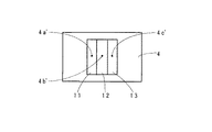
図5は、従来技術の例としての超音波振動素子と振動板の平面図であり、複数の超音波振動素子(11,12,13)が振動板(4)に密着されたものである。4a、4b、4cは振動板の厚み測定部位の例を示す。測定部位4aの板厚:2.75mm、測定部位4bの板厚:2.80mm、測定部位4cの板厚:3.10mmであり、板厚のばらつきは最大0.35mm(厚みむら:12%)である。
このとき各超音波振動素子と振動板との共振周波数は、超音波振動素子11での共振周波数の測定値は1055kHzであり、超音波振動素子12での共振周波数の測定値は1036kHzであり、超音波振動素子13での共振周波数の測定値は935kHzである。
従って、振動板の共振周波数のばらつきに換算すると120kHzとなる。
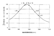
一般的な半導体ウエハーの洗浄には石英槽が用いられており、1MHz程度の超音波エネルギーは石英槽を透過した分が洗浄に寄与することになり、石英槽を透過できる振動周波数対超音波エネルギー透過率の理論特性曲線は、図3の特性図に示されるようなa点(振動板の厚み測定部位4aでの測定値)、b点(振動板の厚み測定部位4bでの測定値)およびc点(振動板の厚み測定部位4cでの測定値)の実測点を有し、最悪の場合、超音波エネルギー透過率は52.4%(a点)になり、半分近くの超音波エネルギーが無駄にされ、洗浄の均一性の観点からも問題視される。
FIG. 5 is a plan view of an ultrasonic vibration element and a diaphragm as an example of the prior art, in which a plurality of ultrasonic vibration elements (11, 12, 13) are in close contact with the diaphragm (4).
At this time, the resonance frequency of each ultrasonic vibration element and the diaphragm is 1055 kHz, the measurement value of the resonance frequency in the
Accordingly, when converted to the variation of the resonance frequency of the diaphragm, 120 kHz is obtained.
Quartz tanks are used for general semiconductor wafer cleaning, and the ultrasonic energy of about 1 MHz contributes to the cleaning by the amount of ultrasonic energy transmitted through the quartz tank. The theoretical characteristic curve of the transmittance has points a (measured values at the diaphragm thickness measurement site 4a), b points (measured values at the diaphragm
洗浄むらを発生させない均一な精度とするような従来技術は、複数の超音波振動素子が並べて配置され、かつ、各超音波振動素子の表面に、その厚み方向にスリット加工が施された構成によるものであった。(例えば、特許文献1参照)。 The conventional technology that achieves uniform accuracy without causing unevenness of cleaning is based on a configuration in which a plurality of ultrasonic vibration elements are arranged side by side and slit processing is performed on the surface of each ultrasonic vibration element in the thickness direction. It was a thing. (For example, refer to Patent Document 1).
年々、洗浄対象物である微細加工品は大型化、微細化が進み、精密洗浄の精度向上が求められて来ており、超音波洗浄装置の超音波振動の不均一に起因する微細粒子等の汚れ剥離不徹底や、大型化、微細化が進むに伴い超音波洗浄装置間での洗浄効果の差が無視できなくなることが問題とされるようになり、更なる均一な超音波振動を発生させ、かつ、装置間での性能差が生じないような、同一精度を有する超音波洗浄装置が必要とされてきた。
そこで、超音波振動の均一性は、用いられる振動板の板厚の均一性に負うところが大ききことが分かっている。
振動板に用いられる市販されているステンレスの板は、公称板厚に対して実質的には、±7.5%程度の許容差が存在し、例として、公称板厚3mmであれば2.73mm〜3・17mmの範囲程度の板が購入され、超音波洗浄装置の振動板として組み立てられた後も、1枚の振動板の振動部位での板厚むら、購入板毎の板厚差異があり、洗浄対象物の大型化、微細化の進みに対して対応しきれない状況となってきた。
Every year, finely processed products that are objects to be cleaned have become larger and more refined, and there has been a demand for improved precision of precision cleaning, such as fine particles resulting from non-uniformity of ultrasonic vibration of ultrasonic cleaning equipment. With the incomplete removal of dirt, the increase in size and miniaturization, it becomes a problem that the difference in cleaning effect between ultrasonic cleaning devices can no longer be ignored, and this causes further uniform ultrasonic vibration. In addition, there has been a need for an ultrasonic cleaning apparatus having the same accuracy that does not cause a difference in performance between apparatuses.
Therefore, it has been found that the uniformity of ultrasonic vibration is greatly influenced by the uniformity of the thickness of the diaphragm used.
A commercially available stainless steel plate used for the diaphragm has a tolerance of about ± 7.5% with respect to the nominal plate thickness. For example, if the nominal plate thickness is 3 mm, 2. Even after a plate in the range of 73mm to 3.17mm is purchased and assembled as a vibration plate for an ultrasonic cleaning device, the plate thickness unevenness at the vibration part of one vibration plate and the plate thickness difference for each purchased plate Yes, it has become a situation that can not cope with the progress of the enlargement and miniaturization of the object to be cleaned.
本発明の目的は、上記従来技術の問題点を解決するために、共振周波数が振動板の全部位で一定に保たれるようにして、被洗浄物に対して常に均一な精密洗浄が行える超音波洗浄装置を提供することにある。 In order to solve the above-mentioned problems of the prior art, the object of the present invention is to ensure that the object to be cleaned can always be precisely cleaned by keeping the resonance frequency constant at all parts of the diaphragm. To provide a sonic cleaning device.
この目的を達成するために、超音波洗浄装置は、洗浄液が溜められた洗浄槽と、該洗浄槽内の該洗浄液に500kHz以上の超音波振動を伝搬させるための超音波振動体とを備えた超音波洗浄装置であって、
前記超音波振動体は、複数枚の平板状超音波振動素子が振動板上に並べて接着された複合素子配置構造体を有し、
前記複数枚の平板状の超音波振動素子のおのおのは、所定の対象洗浄領域に対して平坦状の超音波放射特性を持つ形状を有し、
前記超音波振動の周波数ばらつきを抑えて前記超音波振動体の全面において実質上均一な超音波放射特性が得られるように研磨加工および研削加工の機械加工により前記振動板の振動部位の板厚差が±3%の範囲内のものとする前記振動板としたものである。
In order to achieve this object, an ultrasonic cleaning apparatus includes a cleaning tank in which a cleaning liquid is stored, and an ultrasonic vibrator for propagating ultrasonic vibrations of 500 kHz or more to the cleaning liquid in the cleaning tank. An ultrasonic cleaning device,
The ultrasonic vibrator has a composite element arrangement structure in which a plurality of plate-like ultrasonic vibrators are arranged and bonded on the diaphragm,
Each of the plurality of flat plate-like ultrasonic vibration elements has a shape having a flat ultrasonic radiation characteristic with respect to a predetermined target cleaning region,
The thickness difference of the vibration part of the diaphragm by mechanical processing of polishing and grinding so as to obtain a substantially uniform ultrasonic radiation characteristic over the entire surface of the ultrasonic vibrator while suppressing frequency variation of the ultrasonic vibration Is the diaphragm that is within the range of ± 3%.
更に、本発明の超音波洗浄装置は、前記洗浄液が溜められた洗浄槽が流水型であることを特徴とするものである。 Furthermore, the ultrasonic cleaning apparatus of the present invention is characterized in that the cleaning tank in which the cleaning liquid is stored is a flowing water type.
従来の共振周波数が150kHz程度のばらつきであったものに対し、本発明の振動板では、振動板板厚精度を±3%で管理すれば、共振周波数の精度は60kHz、さらに、振動板の板圧精度を±1%に管理すれば、共振周波数の精度は20kHzのばらつきまで低減することができる。
半導体ウエハーの洗浄に用いられる石英槽での超音波エネルギー透過率は、従来の20%の損失点を有するものがあったが、これを極めてゼロに近い点に集約できるものとした。
本発明を実施すれば、超音波洗浄装置が洗浄対象物の大型化、微細化の進みに対応した均一な洗浄を得ることができ、かつ、複数の超音波洗浄装置間の洗浄精度のばらつき差を低減させ、常に洗浄むらのない安定した超音波洗浄装置である。
In contrast to the conventional resonance frequency variation of about 150 kHz, in the diaphragm of the present invention, if the diaphragm thickness accuracy is managed at ± 3%, the accuracy of the resonance frequency is 60 kHz, and the diaphragm plate If the pressure accuracy is managed at ± 1%, the accuracy of the resonance frequency can be reduced to a variation of 20 kHz.
The ultrasonic energy transmittance in a quartz tank used for cleaning semiconductor wafers has a conventional loss point of 20%, but this can be collected at a point that is extremely close to zero.
By carrying out the present invention, the ultrasonic cleaning apparatus can obtain uniform cleaning corresponding to the progress of the enlargement and miniaturization of the object to be cleaned, and the difference in cleaning accuracy among the plurality of ultrasonic cleaning apparatuses. This is a stable ultrasonic cleaning device that always reduces cleaning unevenness.
図1は、本発明の超音波洗浄装置の実施例1の断面図である。
1は1MHz程度の超音波を発振させる複数の超音波振動素子である。例示では、3つの超音波振動素子で構成されている。
2は超音波振動素子を振動板に密着させた接着部である。3は純水が溜められた外槽である。4は超音波振動素子とともに振動し、純水に振動を伝達させる洗浄槽3の一部を構成する振動板である。5は半導体ウエハーなどを収容して洗浄液に浸すための容器としての石英槽である。6は振動板の振動によって洗浄液が振動する状態を示す超音波振動であり、外槽3内に溜められた純水中を伝搬し、石英槽5の底面を透過して被洗浄物まで到達する。7は洗浄液である。8は半導体ウエハー等の被洗浄物である。9は超音波振動素子を励振させる高周波励振電源である。
外槽3内の純水に500kHz以上の超音波振動6を伝搬させるため複数の超音波振動素子1と振動板4とで超音波振動体が形成される。この超音波振動体は、複数枚の平板状超音波振動素子が振動板上に並べて接着された複合素子配置構造体を有している。
複数の超音波振動素子1のおのおのは、平板状であり、決められた対象洗浄領域に対して平坦状の超音波放射特性を持つ形状を有している。
FIG. 1 is a cross-sectional view of an ultrasonic cleaning apparatus according to a first embodiment of the present invention.
In order to propagate the
Each of the plurality of
実施例1の超音波洗浄装置の動作を説明する。
半導体ウエハー等の被洗浄物8が石英槽5に収容されて、洗浄液7が満たされ、石英槽5が振動板4と一体化された外槽3に浸されている状態で、高周波励振電源9が超音波振動素子1を励振させ、これにともない振動板4が共振し、さらに、振動板4の振動によって外槽3内の純水が振動して、石英槽5内の洗浄液7に超音波振動6を得る。
洗浄液7の超音波振動6は、石英槽5の底面を透過して被洗浄物8の対象洗浄領域に均等に振動が当てられ、被洗浄物8の表面に付着した微細なごみを被洗浄物8から除去させる。
Operation | movement of the ultrasonic cleaning apparatus of Example 1 is demonstrated.
An object to be cleaned 8 such as a semiconductor wafer is accommodated in the quartz tank 5, filled with the
The
次に、実施例1の超音波洗浄装置の振動板4の板厚を管理するための機械加工に関して説明する。
複数枚の平板状の超音波振動素子1が振動板4の上に並べて接着されて複合素子配置構造体に形成された超音波振動体であり、複数枚の平板状超音波振動素子1のおのおのが所定の対象洗浄領域に対して平坦状の超音波放射特性を持つ形状に形成される。
超音波振動6の周波数ばらつきを抑えて超音波振動体の全面において実質上均一な超音波放射特性が得られるように振動板4の表面を研磨して振動部位の板厚差1%以下の板厚精度に形成する。
外槽の底部を成す振動板4の板厚加工については、公称板圧3mm程度の市販ステンレス板を用いたとき、現在の機械加工技術によれば、この市販ステンレス板に対して研削・研磨加工を加えれば±0.02mm程度の精度に厚さの仕上げを行うことが可能である。
これによって振動板の各部位での板厚(d)のばらつきを±0.02mm程度以内に、また、量産したときの、各装置の振動板の板厚(d)のばらつきをも±0.02mm程度以内に抑えることの板厚の精度管理が行える。
Next, machining for managing the plate thickness of the
A plurality of flat plate-like
The surface of the
Regarding the plate thickness processing of the
As a result, the variation of the plate thickness (d) in each part of the diaphragm is within about ± 0.02 mm, and the variation in the plate thickness (d) of the diaphragm of each apparatus when mass-produced is also ± 0. It is possible to manage the accuracy of the plate thickness to be within about 02 mm.
次に、実施例1の超音波洗浄装置の超音波振動体における振動板の板厚と振動周波数の関係について説明する。
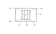
図2は、本発明の超音波洗浄装置の超音波振動素子と振動板とが密着された平面図であり、複数の超音波振動素子(11,12,13)が1枚の振動板(4)に密着されたものである。4a’、4b’、4c’は超音波振動素子(11,12,13)に対応して振動板の厚み(図1(d))の各測定部位の例を示す。
測定部位4a’の板厚d=2.930mm、測定部位4b’の板厚d=2.960mmおよび測定部位4c’の板厚d=2.980mmであり、板厚のばらつきは最大0.05mm(厚みむら:1.7%)である。
このとき各超音波振動素子(11,12,13)と振動板との共振周波数は、超音波振動素子11での共振周波数の測定値は990kHz、超音波振動素子12での共振周波数の測定値は980kHz、超音波振動素子13での共振周波数の測定値は973kHzである。従って、振動板の共振周波数のばらつきは17kHzとなる。
Next, the relationship between the plate thickness of the vibration plate and the vibration frequency in the ultrasonic vibrating body of the ultrasonic cleaning apparatus according to the first embodiment will be described.
FIG. 2 is a plan view in which the ultrasonic vibration element and the vibration plate of the ultrasonic cleaning apparatus of the present invention are brought into close contact with each other, and a plurality of ultrasonic vibration elements (11, 12, 13) includes one vibration plate (4). ). Reference numerals 4a ′, 4b ′, and 4c ′ denote examples of measurement portions of the thickness of the diaphragm (FIG. 1D) corresponding to the ultrasonic vibration elements (11, 12, 13).
The thickness d = 2.930 mm of the measurement site 4a ′, the thickness d = 2.960 mm of the
At this time, the resonance frequency of each ultrasonic vibration element (11, 12, 13) and the diaphragm is 990 kHz for the measurement value of the resonance frequency in the
図3は、本発明の超音波洗浄装置の石英槽における超音波エネルギー透過率特性曲線であり、縦軸が超音波エネルギー透過率(%)であり、横軸が超音波振動周波数(kHz)である。
現在、多くの半導体ウエハーの洗浄には石英槽が用いられており、超音波エネルギーは石英槽を透過した分が被洗浄物の洗浄に寄与することになり、石英槽を透過できる振動周波数対超音波エネルギー透過率の理論特性曲線は、図3の特性曲線に示される。
本発明での実験値として、a’点は測定部位4a’における超音波エネルギー透過率が99.6%、b’点 は測定部位4b’における超音波エネルギー透過率が99.5%およびc’点 は測定部位4c’における超音波エネルギー透過率が97.4%で示される。
この時の超音波エネルギー透過率は最悪でも97.4%であり、これであれば、ほとんど減衰なく、良好に透過し、均一な洗浄が行える。
このようにして、超音波振動の周波数ばらつきを抑えて超音波振動体の全面において実質上均一な超音波放射特性が得られるように石英エネルギー透過率が80%を超えることを最低限の条件とし、振動板の振動部位の板厚差±3%以下のものとする振動板とした。
なお、振動板の板厚の管理精度を更に向上させれば、更なる、微細加工された被洗浄物に対応させることが可能である。いずれの管理精度を選択するかは。コスト/パフォーマンスを考慮すればよい。洗浄用途の違い毎に、どれくらいの管理精度が必要であるか十分に見極めて板厚制度を±3%に条件付けたり、±1%に条件付けたり、価格と性能のトレードオフを考慮して決めればよい。
FIG. 3 is an ultrasonic energy transmittance characteristic curve in the quartz tank of the ultrasonic cleaning apparatus of the present invention, the vertical axis is the ultrasonic energy transmittance (%), and the horizontal axis is the ultrasonic vibration frequency (kHz). is there.
At present, a quartz tank is used for cleaning many semiconductor wafers, and the amount of ultrasonic energy transmitted through the quartz tank contributes to the cleaning of the object to be cleaned. The theoretical characteristic curve of sonic energy transmittance is shown in the characteristic curve of FIG.
As experimental values in the present invention, the a ′ point has an ultrasonic energy transmittance of 99.6% at the measurement site 4a ′, the b ′ point has an ultrasonic energy transmittance of 99.5% at the
At this time, the ultrasonic energy transmittance is 97.4% at the worst. If this is the case, the transmittance is good with almost no attenuation and uniform cleaning can be performed.
In this way, it is a minimum condition that the quartz energy transmittance exceeds 80% so that a substantially uniform ultrasonic radiation characteristic can be obtained on the entire surface of the ultrasonic vibration member while suppressing the frequency variation of the ultrasonic vibration. A diaphragm having a plate thickness difference of ± 3% or less at the vibrating portion of the diaphragm was used.
In addition, if the management accuracy of the plate thickness of the diaphragm is further improved, it is possible to cope with a further finely processed object to be cleaned. Which management accuracy should be selected? Cost / performance should be considered. If the difference in cleaning application is enough to determine how much control accuracy is required, the thickness system should be conditioned to ± 3% or conditioned to ± 1%, considering the trade-off between price and performance. Good.
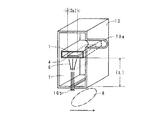
図4は、本発明の超音波洗浄装置の実施例2の断面斜視図であり、流水型の超音波洗浄装置の構造を示している。
1は1MHz程度の超音波を発振させる図示してはいないが複数の超音波振動素子で構成された振動素子幅(2e)の複合された超音波振動素子である。
4は超音波振動素子とともに振動し、洗浄液に振動を伝達させる振動板である。
6は振動板の振動によって洗浄液が振動する状態を示す超音波振動であり、洗浄液溜槽内に流水となって溜められた洗浄液中を伝搬し、噴射口から洗浄液が噴出して被洗浄物まで到達する。
7は洗浄液である。
8は噴射された洗浄液が洗浄面に突き当り、移動させながら洗浄が行われる半導体ウエハー等の被洗浄物である。
10は、複合された超音波振動素子と振動板4とを内蔵させ、水圧かけられた洗浄液を注ぎ込む給液口10aと超音波振動が伴った圧力が掛けられた洗浄液を噴射させる噴射口10bが配設され、振動板4の底面から噴射口10bの内壁面までの距離(L)を有する洗浄液溜槽である。
図示してはいないが超音波振動素子を励振させる高周波励振電源を外部に有する。
FIG. 4 is a cross-sectional perspective view of the ultrasonic cleaning apparatus according to the second embodiment of the present invention, and shows the structure of a flowing water type ultrasonic cleaning apparatus.
6 is an ultrasonic vibration showing a state in which the cleaning liquid vibrates due to the vibration of the vibration plate. The ultrasonic vibration propagates through the cleaning liquid stored as running water in the cleaning liquid reservoir, and the cleaning liquid spouts from the injection port to reach the object to be cleaned. To do.
Reference numeral 8 denotes an object to be cleaned such as a semiconductor wafer in which cleaning is performed while the sprayed cleaning liquid hits the cleaning surface and is moved.
10 includes a composite ultrasonic vibration element and a
Although not shown, a high-frequency excitation power source for exciting the ultrasonic vibration element is provided outside.
実施例2の動作を説明する。
半導体ウエハー等の被洗浄物8が本発明の流水型の超音波洗浄装置の洗浄溜槽10に有する噴射口10bの下部に配置されて、水圧がかけられた洗浄液7が給液口10aから注ぎ込まれた状態で、図示していないが高周波励振電源3は超音波振動素子1を励振させると振動板4が共振し、さらに、この振動によって洗浄液が振動して、洗浄液の超音波振動6を得る。
超音波振動6が収束距離(L)を経て収束されて、スリット状をした噴射口10bからの超音波振動6を伴う洗浄液が、被洗浄物8の対象洗浄領域に噴射して噴射口10bのスリット方向に均一な振動が当てられ、さらに被洗浄物8は矢印の方向に移動することによって、被洗浄物8の洗浄面に均等に噴射されて、被洗浄物8の表面に付着した微細なごみを被洗浄物8から除去させる。
なお、洗浄溜槽10内に配設された振動板4の板厚の精度向上の加工については、実施例1の超音波洗浄装置の振動板4の板厚を管理するための機械加工に関しての説明と同様であるのでその説明は省略する。
The operation of the second embodiment will be described.
An object to be cleaned 8 such as a semiconductor wafer is disposed below the
The
In addition, about the process for improving the accuracy of the thickness of the
流水型の超音波洗浄装置の超音波の共振周波数と収束距離の関係について説明する。
超音波を効率よく噴射させるために、振動素子幅に比較して狭い噴射口(スリット)にすることにより、収束させた超音波を噴射させることができる。
この超音波の収束は、振動素子の振動面の幅および振動面から噴射口までの距離を所定の値にすることにより行われる。
収束距離を求める関係式として、先ず、振動板の板厚と共振周波数との関係式を(1)式に、流水型洗浄機の収束距離Lの関係式を(2)式を示す。この関係式によって得られた各値を表1に示す。
The relationship between the ultrasonic resonance frequency and the convergence distance of the flowing water type ultrasonic cleaning apparatus will be described.
In order to efficiently eject the ultrasonic waves, the converged ultrasonic waves can be ejected by making the ejection port (slit) narrower than the vibration element width.
The convergence of the ultrasonic wave is performed by setting the width of the vibration surface of the vibration element and the distance from the vibration surface to the ejection port to predetermined values.
As a relational expression for obtaining the convergence distance, first, the relational expression between the plate thickness of the diaphragm and the resonance frequency is represented by Expression (1), and the relational expression of the convergence distance L of the flowing water type washing machine is represented by Expression (2). Table 1 shows the values obtained by this relational expression.

従って、共振周波数のばらつきが生ずると、超音波振動波の収束距離の違いとなって現れる。この収束距離の違いが洗浄むらとして影響を及ぼす。
共振周波数と集束距離の関係から得られた計算表である表1に示す値から次のことが説明できる。
板厚偏差が±7.5%の振動板(従来)では、±値それぞれの収束距離(L)の差は92.2−79.4=12.8mmとなるのに対して、本願発明のように板厚偏差が±3%であれば、収束距離(L)の差は88.4−83.2=5.2mmとなる。さらに板厚偏差が±1%であれば、収束距離(L)の差は86.7−85=1.7mmとなり、洗浄の均一性に大きく影響していることは明らかである。
Therefore, when the resonance frequency varies, it appears as a difference in the convergence distance of the ultrasonic vibration wave. This difference in convergence distance has an effect as uneven cleaning.
The following can be explained from the values shown in Table 1, which is a calculation table obtained from the relationship between the resonance frequency and the focusing distance.
In the diaphragm (conventional) having a thickness deviation of ± 7.5%, the difference in the convergence distance (L) of each ± value is 92.2-79.4 = 12.8 mm. Thus, if the plate thickness deviation is ± 3%, the difference in the convergence distance (L) is 88.4-83.2 = 5.2 mm. Further, if the plate thickness deviation is ± 1%, the difference in the convergence distance (L) is 86.7−85 = 1.7 mm, which clearly affects the cleaning uniformity.
本発明は、半導体ウエハー、ガラスマスク、液晶ガラス基板、ハードディスク盤など微細加工品の製造ラインにおける精密洗浄を必要とされる主に製造業に利用することができる。 INDUSTRIAL APPLICABILITY The present invention can be used mainly in the manufacturing industry that requires precision cleaning in a production line for finely processed products such as semiconductor wafers, glass masks, liquid crystal glass substrates, and hard disk boards.
1,11,12,13 超音波振動素子
2 接着部
3 外槽
4 振動板
4a、4b、4c、4a’、4b’、4c’ 振動板部位
5 石英槽
6 超音波振動
7 洗浄液
8 被洗浄物
9 高周波励振電源
10 洗浄液溜槽
10a 給液口
10b 噴射口
DESCRIPTION OF
Claims (2)
前記超音波振動体は、複数枚の平板状超音波振動素子が振動板上に並べて接着された複合素子配置構造体を有し、
前記複数枚の平板状の超音波振動素子のおのおのは、所定の対象洗浄領域に対して平坦状の超音波放射特性を持つ形状を有し、
前記超音波振動の周波数ばらつきを抑えて前記超音波振動体の全面において実質上均一な超音波放射特性が得られるように研磨加工および研削加工の機械加工により前記振動板の振動部位の板厚差が±3%の範囲内のものとする前記振動板としたことを特徴とする超音波洗浄装置。 An ultrasonic cleaning apparatus comprising: a cleaning tank in which a cleaning liquid is stored; and an ultrasonic vibrator for propagating ultrasonic vibrations of 500 kHz or more to the cleaning liquid in the cleaning tank,
The ultrasonic vibrator has a composite element arrangement structure in which a plurality of plate-like ultrasonic vibrators are arranged and bonded on the diaphragm,
Each of the plurality of flat plate-like ultrasonic vibration elements has a shape having a flat ultrasonic radiation characteristic with respect to a predetermined target cleaning region,
The thickness difference of the vibration part of the diaphragm by mechanical processing of polishing and grinding so as to obtain a substantially uniform ultrasonic radiation characteristic over the entire surface of the ultrasonic vibrator while suppressing frequency variation of the ultrasonic vibration An ultrasonic cleaning apparatus characterized in that the vibration plate has a value within a range of ± 3%.
Priority Applications (1)
| Application Number | Priority Date | Filing Date | Title |
|---|---|---|---|
| JP2006098459A JP4733550B2 (en) | 2006-03-31 | 2006-03-31 | Ultrasonic cleaning equipment |
Applications Claiming Priority (1)
| Application Number | Priority Date | Filing Date | Title |
|---|---|---|---|
| JP2006098459A JP4733550B2 (en) | 2006-03-31 | 2006-03-31 | Ultrasonic cleaning equipment |
Publications (3)
| Publication Number | Publication Date |
|---|---|
| JP2007268448A true JP2007268448A (en) | 2007-10-18 |
| JP2007268448A5 JP2007268448A5 (en) | 2008-10-16 |
| JP4733550B2 JP4733550B2 (en) | 2011-07-27 |
Family
ID=38671796
Family Applications (1)
| Application Number | Title | Priority Date | Filing Date |
|---|---|---|---|
| JP2006098459A Active JP4733550B2 (en) | 2006-03-31 | 2006-03-31 | Ultrasonic cleaning equipment |
Country Status (1)
| Country | Link |
|---|---|
| JP (1) | JP4733550B2 (en) |
Cited By (4)
| Publication number | Priority date | Publication date | Assignee | Title |
|---|---|---|---|---|
| JP2010125372A (en) * | 2008-11-26 | 2010-06-10 | Yamagata Shin-Etsu Quartz Co Ltd | Glass washing tank and ultrasonic cleaning device |
| WO2013099728A1 (en) * | 2011-12-28 | 2013-07-04 | コニカミノルタ株式会社 | Production method for glass substrate for information recording medium |
| CN104998859A (en) * | 2015-07-01 | 2015-10-28 | 佛山市灿东模具技术有限公司 | Adhered aluminum washing device for wheel hub mould |
| CN104998858A (en) * | 2015-07-01 | 2015-10-28 | 佛山市灿东模具技术有限公司 | Device for cleaning aluminum bonded on hub mold |
Families Citing this family (1)
| Publication number | Priority date | Publication date | Assignee | Title |
|---|---|---|---|---|
| CN102515305A (en) * | 2012-01-18 | 2012-06-27 | 天津壹帆水务有限公司 | Ultrasonic wave washing and ultraviolet disinfecting device |
Citations (2)
| Publication number | Priority date | Publication date | Assignee | Title |
|---|---|---|---|---|
| JP2003158110A (en) * | 2001-09-04 | 2003-05-30 | Alps Electric Co Ltd | Wet treatment nozzle and device thereof |
| JP2004249212A (en) * | 2003-02-20 | 2004-09-09 | Kokusai Electric Alhpa Co Ltd | Ultrasonic cleaning device |
Family Cites Families (1)
| Publication number | Priority date | Publication date | Assignee | Title |
|---|---|---|---|---|
| JPH0556285U (en) * | 1992-01-07 | 1993-07-27 | 株式会社カイジョー | Ultrasonic cleaning equipment |
-
2006
- 2006-03-31 JP JP2006098459A patent/JP4733550B2/en active Active
Patent Citations (2)
| Publication number | Priority date | Publication date | Assignee | Title |
|---|---|---|---|---|
| JP2003158110A (en) * | 2001-09-04 | 2003-05-30 | Alps Electric Co Ltd | Wet treatment nozzle and device thereof |
| JP2004249212A (en) * | 2003-02-20 | 2004-09-09 | Kokusai Electric Alhpa Co Ltd | Ultrasonic cleaning device |
Cited By (6)
| Publication number | Priority date | Publication date | Assignee | Title |
|---|---|---|---|---|
| JP2010125372A (en) * | 2008-11-26 | 2010-06-10 | Yamagata Shin-Etsu Quartz Co Ltd | Glass washing tank and ultrasonic cleaning device |
| WO2013099728A1 (en) * | 2011-12-28 | 2013-07-04 | コニカミノルタ株式会社 | Production method for glass substrate for information recording medium |
| CN104998859A (en) * | 2015-07-01 | 2015-10-28 | 佛山市灿东模具技术有限公司 | Adhered aluminum washing device for wheel hub mould |
| CN104998858A (en) * | 2015-07-01 | 2015-10-28 | 佛山市灿东模具技术有限公司 | Device for cleaning aluminum bonded on hub mold |
| CN104998859B (en) * | 2015-07-01 | 2017-03-01 | 佛山市灿东模具技术有限公司 | Hub mold glues aluminum cleaning device |
| CN104998858B (en) * | 2015-07-01 | 2017-06-13 | 佛山市灿东模具技术有限公司 | For the device of the viscous aluminium cleaning of hub mold |
Also Published As
| Publication number | Publication date |
|---|---|
| JP4733550B2 (en) | 2011-07-27 |
Similar Documents
| Publication | Publication Date | Title |
|---|---|---|
| JP4733550B2 (en) | Ultrasonic cleaning equipment | |
| KR101384595B1 (en) | Ultrasonic cleaning apparatus and ultrasonic cleaning method | |
| KR20110090120A (en) | An ultrasonic cleaner and method thereof | |
| JP2003340386A (en) | Ultrasonic cleaning apparatus and method therefor | |
| US20020026976A1 (en) | Ultrasonic vibrator, wet-treatment nozzle, and wet-treatment apparatus | |
| JP2001313537A (en) | Piezoelectric element and its manufacturing method | |
| JP2007044662A (en) | Ultrasonic cleaner | |
| JPH0234923A (en) | Ultrasonic cleaner | |
| JP2009125645A (en) | Ultrasonic washing device and ultrasonic washing method | |
| JP2004249212A (en) | Ultrasonic cleaning device | |
| KR100579613B1 (en) | Ultrasonic cleaner and nozzle for it | |
| JP4533406B2 (en) | Ultrasonic cleaning apparatus and ultrasonic cleaning method | |
| US20100108111A1 (en) | Ultrasonic cleaning apparatus | |
| KR101017104B1 (en) | Supersonic nozzle and wafer cleaning apparatus compring the same | |
| JP2010207935A (en) | Wafer machining method and numerical control blasting device | |
| JP5592734B2 (en) | Ultrasonic cleaning apparatus and ultrasonic cleaning method | |
| JP4144201B2 (en) | Wet cleaning processing equipment | |
| KR100986586B1 (en) | The ultrasonic oscillator | |
| JP2011131177A (en) | Washing jig | |
| JP2007050377A (en) | Ultrasonic washer and frequency matching method | |
| JP2004312286A (en) | Manufacturing method of piezoelectric substrate | |
| JP2007266194A (en) | Cleaning method of semiconductor substrate, and cleaning apparatus of semiconductor substrate using it | |
| JPH0232525A (en) | Supersonic washing device | |
| JP2022078147A (en) | Ultrasonic shower washing device | |
| KR20100047462A (en) | Substrate cleaning apparatus and method for cleaning the substrate using the same |
Legal Events
| Date | Code | Title | Description |
|---|---|---|---|
| A521 | Request for written amendment filed |
Free format text: JAPANESE INTERMEDIATE CODE: A523 Effective date: 20080901 |
|
| A621 | Written request for application examination |
Free format text: JAPANESE INTERMEDIATE CODE: A621 Effective date: 20080901 |
|
| RD03 | Notification of appointment of power of attorney |
Free format text: JAPANESE INTERMEDIATE CODE: A7423 Effective date: 20080901 |
|
| A977 | Report on retrieval |
Free format text: JAPANESE INTERMEDIATE CODE: A971007 Effective date: 20100707 |
|
| A131 | Notification of reasons for refusal |
Free format text: JAPANESE INTERMEDIATE CODE: A131 Effective date: 20100713 |
|
| A521 | Request for written amendment filed |
Free format text: JAPANESE INTERMEDIATE CODE: A523 Effective date: 20100908 |
|
| TRDD | Decision of grant or rejection written | ||
| A01 | Written decision to grant a patent or to grant a registration (utility model) |
Free format text: JAPANESE INTERMEDIATE CODE: A01 Effective date: 20110329 |
|
| A61 | First payment of annual fees (during grant procedure) |
Free format text: JAPANESE INTERMEDIATE CODE: A61 Effective date: 20110422 |
|
| FPAY | Renewal fee payment (event date is renewal date of database) |
Free format text: PAYMENT UNTIL: 20140428 Year of fee payment: 3 |
|
| R150 | Certificate of patent or registration of utility model |
Free format text: JAPANESE INTERMEDIATE CODE: R150 Ref document number: 4733550 Country of ref document: JP Free format text: JAPANESE INTERMEDIATE CODE: R150 |
|
| R250 | Receipt of annual fees |
Free format text: JAPANESE INTERMEDIATE CODE: R250 |
|
| R250 | Receipt of annual fees |
Free format text: JAPANESE INTERMEDIATE CODE: R250 |
|
| R250 | Receipt of annual fees |
Free format text: JAPANESE INTERMEDIATE CODE: R250 |
|
| R250 | Receipt of annual fees |
Free format text: JAPANESE INTERMEDIATE CODE: R250 |
|
| S111 | Request for change of ownership or part of ownership |
Free format text: JAPANESE INTERMEDIATE CODE: R313113 Free format text: JAPANESE INTERMEDIATE CODE: R313111 |
|
| R350 | Written notification of registration of transfer |
Free format text: JAPANESE INTERMEDIATE CODE: R350 |
|
| R250 | Receipt of annual fees |
Free format text: JAPANESE INTERMEDIATE CODE: R250 |
|
| R250 | Receipt of annual fees |
Free format text: JAPANESE INTERMEDIATE CODE: R250 |
|
| R250 | Receipt of annual fees |
Free format text: JAPANESE INTERMEDIATE CODE: R250 |
|
| R250 | Receipt of annual fees |
Free format text: JAPANESE INTERMEDIATE CODE: R250 |
|
| R250 | Receipt of annual fees |
Free format text: JAPANESE INTERMEDIATE CODE: R250 |
|
| R250 | Receipt of annual fees |
Free format text: JAPANESE INTERMEDIATE CODE: R250 |
|
| R250 | Receipt of annual fees |
Free format text: JAPANESE INTERMEDIATE CODE: R250 |