JP2007263154A - Vibration absorbing bush assembly - Google Patents
Vibration absorbing bush assembly Download PDFInfo
- Publication number
- JP2007263154A JP2007263154A JP2006085660A JP2006085660A JP2007263154A JP 2007263154 A JP2007263154 A JP 2007263154A JP 2006085660 A JP2006085660 A JP 2006085660A JP 2006085660 A JP2006085660 A JP 2006085660A JP 2007263154 A JP2007263154 A JP 2007263154A
- Authority
- JP
- Japan
- Prior art keywords
- flange portion
- rubber
- vibration
- inner cylinder
- cylinder member
- Prior art date
- Legal status (The legal status is an assumption and is not a legal conclusion. Google has not performed a legal analysis and makes no representation as to the accuracy of the status listed.)
- Withdrawn
Links
Images


Abstract
Description
本発明は、自動車の車輪懸架装置においてサスペンションアームの車体への枢支連結部等に介装されて、サスペンションアームを車体に対して揺動可能に防振連結する防振ブッシュ組立体に関する。 The present invention relates to an anti-vibration bushing assembly that is interposed in a pivotal support connection portion or the like of a suspension arm to a vehicle body in an automobile wheel suspension device and that anti-vibrates and connects the suspension arm to the vehicle body.
従来より、自動車の車輪懸架装置においてサスペンションアームの車体への枢支連結部等に介装される防振ブッシュ組立体の一種として、例えば特許文献1〜3等に開示されているものが知られている。これらの防振ブッシュ組立体は、一般に、パイプ状に形成されて軸方向一端に外向きフランジ部を有する内筒部材と、筒状に形成されて軸方向一端に外向きフランジ部を有し内筒部材の外周側に距離を隔てて同軸的に配置された外筒部材と、それら内筒部材と外筒部材の径方向対向面間を連結するゴム本体部及び各外向きフランジ部の軸方向対向面間を連結するゴムフランジ部を有し両部材を弾性的に連結するゴム弾性体とからなる一対の防振ブッシュを用い、それらの防振ブッシュを、サスペンションアームの端部に形成された筒状のアームアイに対して軸方向両側から挿入させて、各外筒部材をアームアイに嵌着した後、車体側に形成された所定距離を隔てて対向する一対の取付板部間に嵌め込み、両内筒部材をそれら取付板部間で軸支させることによりアームアイを取付板部に対して防振連結するようにされている。 2. Description of the Related Art Conventionally, as a type of vibration-proof bushing assembly that is interposed in a pivot support connecting portion of a suspension arm to a vehicle body in an automobile wheel suspension device, for example, those disclosed in Patent Documents 1 to 3 are known. ing. These anti-vibration bush assemblies are generally formed in a pipe shape and have an inner cylindrical member having an outward flange portion at one axial end, and an inner cylindrical member formed in a cylindrical shape and having an outward flange portion at one axial end. An outer cylinder member coaxially arranged on the outer peripheral side of the cylinder member with a distance therebetween, an axial direction of the rubber main body portion connecting the radially opposed surfaces of the inner cylinder member and the outer cylinder member, and each outward flange portion A pair of anti-vibration bushes having a rubber flange portion for connecting the opposing surfaces and a rubber elastic body for elastically connecting both members was used, and these anti-vibration bushes were formed at the end of the suspension arm. Inserted from both sides in the axial direction with respect to the cylindrical arm eye, each outer cylinder member is fitted to the arm eye, and then fitted between a pair of mounting plate portions facing each other with a predetermined distance formed on the vehicle body side. The inner cylinder member is pivotally supported between these mounting plates. It is adapted to vibration damped linkage of Amuai to the attachment plate portion by causing.
また、このような防振ブッシュ組立体においては、一般に、各防振ブッシュの外筒部材に対して、アームアイへの装着前の縮径加工やアームアイへの圧入による縮径化等によって絞り作用が加えられることにより、内筒部材と外筒部材の径方向対向面間に介在するゴム本体部に予圧縮が加えられるとともに、一対の取付板部間に一対の防振ブッシュを嵌め込んだ後、両防振ブッシュの内筒部材に挿通された枢軸を介して、一対の取付板部間で両防振ブッシュの内筒部材を軸方向に締め込むことにより、内筒部材と外筒部材の各外向きフランジ部の軸方向対向面間に介在するゴムフランジ部に予圧縮が加えられる。そして、これらの予圧縮により、ゴム弾性体における引張応力の発生が軽減乃至防止されて耐久性の向上が図られるとともに、目的とする防振特性が付与されるのである。 In such an anti-vibration bushing assembly, generally, the outer cylinder member of each anti-vibration bushing has a drawing action by reducing the diameter before mounting on the arm eye or by reducing the diameter by press-fitting into the arm eye. By being added, pre-compression is applied to the rubber main body portion interposed between the radially opposed surfaces of the inner cylinder member and the outer cylinder member, and after fitting a pair of vibration isolating bushes between the pair of mounting plate parts, Each of the inner cylinder member and the outer cylinder member is secured by axially tightening the inner cylinder member of both vibration isolation bushes between a pair of mounting plates through a pivot inserted into the inner cylinder members of both vibration isolation bushings. Pre-compression is applied to the rubber flange portion interposed between the axially opposed surfaces of the outward flange portion. These pre-compressions reduce or prevent the generation of tensile stress in the rubber elastic body, thereby improving the durability and providing the desired vibration isolation characteristics.
ところで、このような防振ブッシュ組立体には、その装着状態下で、内筒部材と外筒部材の間に軸方向の荷重や捩じり方向の荷重が入力された際に、内筒部材と外筒部材の両外向きフランジ部間を連結するゴムフランジ部に対して引張荷重が及ぼされることがある。一方、上記のように、防振ブッシュ組立体をサスペンションアームと車体の間に介装して使用する際に、内筒部材又は外筒部材に対して軸方向の初期荷重が負荷された状態に取り付けられるという特殊な場合がある。この場合には、内筒部材と外筒部材を軸方向に相対変位させるように作用する初期荷重が既に負荷された状態で使用されるため、軸方向において初期荷重が入力する側と反対側に配置されている一方の防振ブッシュにおいては、両外向きフランジ部間を連結するゴムフランジ部に対して付与されていた予圧縮が解除された状態、或いは引張荷重が入力された状態になる。そのため、自動車の走行時等において更に捩じり方向の荷重が入力すると、両外向きフランジ部間を連結するゴムフランジ部には大きな引張荷重が入力されることとなり、そのゴムフランジ部の耐久性が著しく低下してしまうという問題が発生する。
本発明は上記問題に鑑みてなされたものであり、それぞれ軸方向一端に外向きフランジ部を有する内筒部材と外筒部材を備えた防振ブッシュが2個組み付けられた防振ブッシュ組立体において、軸方向の荷重が入力された際に内筒部材と外筒部材の外向きフランジ部間を連結するゴムフランジ部に対して引張荷重が入力する側に配置される防振ブッシュの耐久性を向上し得るようにした防振ブッシュ組立体を提供することを解決すべき課題とするものである。 The present invention has been made in view of the above problems, and is an anti-vibration bush assembly in which two inner cylinder members each having an outward flange portion at one axial end and an anti-vibration bush including the outer cylinder member are assembled. The durability of the anti-vibration bush placed on the side where the tensile load is input relative to the rubber flange that connects between the outward flanges of the inner and outer cylinder members when the axial load is input An object of the present invention is to provide a vibration-proof bushing assembly that can be improved.
上記課題を解決する本発明は、軸方向一端に外向きフランジ部を有する内筒部材と、軸方向一端に外向きフランジ部を有し前記内筒部材の外周側に距離を隔てて同軸状に配設された外筒部材と、前記内筒部材と前記外筒部材の径方向対向面間を連結するゴム本体部および各前記外向きフランジ部の軸方向対向面間を連結するゴムフランジ部を有し両部材を弾性的に連結するゴム弾性体とからなる防振ブッシュを2個用いて、取付筒部材の装着孔に軸方向両側から各前記内筒部材および各前記外筒部材の前記外向きフランジ部と反対側の端面どうしが対向するように挿入させることにより、両前記外筒部材が前記装着孔に嵌着された状態に組み付けられた防振ブッシュ組立体において、一方の前記ゴムフランジ部は、他方の前記ゴムフランジ部よりも軸方向長さが長くされているとともに、各前記内筒部材の前記外向きフランジ部と反対側の端面どうしが当接した状態のときに、一方の前記ゴムフランジ部と他方の前記ゴムフランジ部に異なる量の予圧縮が付与されるように構成されていることを特徴としている。 The present invention that solves the above-mentioned problems has an inner cylindrical member having an outward flange portion at one axial end, and an outer flange portion at one axial end, and is coaxially spaced from the outer peripheral side of the inner cylindrical member. An outer cylinder member disposed; a rubber main body portion that connects between the radially opposed surfaces of the inner cylinder member and the outer cylinder member; and a rubber flange portion that connects between the axially opposed surfaces of the outward flange portions. And using two anti-vibration bushes composed of a rubber elastic body that elastically connects the two members, and the outer cylindrical members and the outer cylindrical members are attached to the mounting holes of the mounting cylindrical members from both sides in the axial direction. In the vibration-proof bushing assembly in which both the outer cylinder members are fitted in the mounting holes by inserting the end surfaces on the opposite side to the facing flange portion, the one rubber flange Part is the other rubber flange part When the axial length of the inner cylinder member is increased and the end surfaces of the inner cylinder members opposite to the outward flange portions are in contact with each other, the one rubber flange portion and the other rubber portion It is characterized in that different amounts of pre-compression are applied to the flange portion.
本発明の防振ブッシュ組立体は、自動車のサスペンションアームと車体の枢支連結部等に介装されて使用される場合に、軸方向長さが長くされているゴムフランジ部を有する防振ブッシュが、軸方向の荷重が入力する側と反対側に位置するように取り付けられる。即ち、その防振ブッシュは、軸方向の荷重が入力された際に、内筒部材と外筒部材の外向きフランジ部間を連結するゴムフランジ部に対して引張荷重が入力する側に配置される。これにより、そのゴムフランジ部は、軸方向及び捩じり方向における自由長がより長くなるようにされているため、軸方向や捩じり方向の荷重が入力された際に生じる歪みが有効に低減されるようになり、耐久性の向上が可能となる。 An anti-vibration bushing assembly according to the present invention includes an anti-vibration bushing having a rubber flange portion whose axial length is increased when used in an automobile suspension arm and a pivot support connection portion of a vehicle body. However, it is attached so that it may be located in the opposite side to the side into which an axial load is input. That is, the anti-vibration bush is arranged on the side where the tensile load is input with respect to the rubber flange portion that connects between the outward flange portions of the inner cylinder member and the outer cylinder member when an axial load is input. The As a result, since the rubber flange portion has a longer free length in the axial direction and the torsional direction, distortion generated when a load in the axial direction or the torsional direction is input is effective. As a result, the durability can be improved.
また、両防振ブッシュの各ゴムフランジ部には、各内筒部材の外向きフランジ部と反対側の端面どうしが当接した状態のときに、異なる量の予圧縮が付与されるようにされており、通常、軸方向長さが長くされているゴムフランジ部に対して他方のゴムフランジ部よりも大きい予圧縮が付与される。これにより、防振ブッシュ組立体が自動車に取り付けられた際に、大きい予圧縮が付与されているゴムフランジ部に対して軸方向の初期荷重が入力された場合でも、そのゴムフランジ部に有効に予圧縮が付与された状態を維持することが可能となる。そのため、そのゴムフランジ部の軸方向長さが長くされていることと相俟って、軸方向や捩じり方向の荷重が入力された際に生じる歪みが有効に低減されるようになり、耐久性の向上が可能となる。 Also, different amounts of pre-compression are applied to the rubber flanges of the anti-vibration bushes when the end surfaces opposite to the outward flanges of the inner cylinder members are in contact with each other. In general, a larger precompression is applied to the rubber flange portion having a longer axial length than the other rubber flange portion. As a result, even when an initial load in the axial direction is input to the rubber flange portion to which a large pre-compression is applied when the vibration-proof bushing assembly is attached to the automobile, the rubber flange portion is effective. It is possible to maintain a state in which pre-compression is applied. Therefore, coupled with the axial length of the rubber flange portion being increased, the distortion that occurs when a load in the axial direction or torsional direction is input is effectively reduced. Durability can be improved.
なお、軸方向長さが長くされているゴムフランジ部に対して充分な予圧縮量の確保が可能な場合には、必ずしも他方のゴムフランジ部よりも大きな予圧縮が付与されている必要はなく、他方のゴムフランジ部よりも小さい予圧縮が付与されるようにしてもよい。このようにするには、例えば、軸方向長さが長くされているゴムフランジ部の外径寸法を、他方のゴムフランジ部の外径寸法よりも大きくすることにより達成できる。 If a sufficient amount of pre-compression can be ensured for the rubber flange portion whose axial length is increased, it is not always necessary to apply a larger pre-compression than the other rubber flange portion. Further, pre-compression smaller than that of the other rubber flange portion may be applied. This can be achieved, for example, by making the outer diameter dimension of the rubber flange portion whose axial length is longer than the outer diameter dimension of the other rubber flange portion.
本発明において、軸方向長さが長くされている一方のゴムフランジ部は、他方のゴムフランジ部よりも予圧縮量が大きくされているのが好ましい。このようにされていれば、軸方向長さが長くされているここと相俟って、軸方向や捩じり方向の荷重が入力された際に生じる歪みをより有効に低減することができ、耐久性の向上を有利に達成することが可能となる。この場合、各ゴムフランジ部に付与される予圧縮量は、各ゴムフランジ部の軸方向のばね定数を調整することにより適宜設定することができる。また、各ゴムフランジ部の軸方向のばね定数は、各ゴムフランジ部の外径寸法を変化させることにより調整することが可能である。 In the present invention, it is preferable that one of the rubber flange portions having a longer axial length has a larger pre-compression amount than the other rubber flange portion. If this is done, combined with the increased axial length, it is possible to more effectively reduce distortion that occurs when an axial or torsional load is input. Thus, it is possible to advantageously achieve improved durability. In this case, the amount of pre-compression applied to each rubber flange portion can be appropriately set by adjusting the axial spring constant of each rubber flange portion. The axial spring constant of each rubber flange portion can be adjusted by changing the outer diameter of each rubber flange portion.
また、本発明において、両内筒部材は、取付筒部材の装着孔に挿入された際に、互いに対向する軸方向端面側の端部に設けられた連結固定部に圧入される連結筒部材により連結されているようにするのが好ましい。この連結筒部材を採用することにより、両内筒部材の各外向きフランジ部の軸方向における相対位置を容易に設定することができるので、各ゴムフランジ部に付与される予圧縮量の調整を容易に行うことができる。 Further, in the present invention, the inner cylindrical members are connected by a connecting cylindrical member that is press-fitted into a connecting fixing portion provided at an end portion on the axial end surface facing each other when inserted into the mounting hole of the mounting cylindrical member. It is preferable to be connected. By adopting this connecting cylinder member, the relative position in the axial direction of each outward flange part of both inner cylinder members can be easily set, so that the amount of precompression applied to each rubber flange part can be adjusted. It can be done easily.
また、本発明の好適な態様として、両防振ブッシュは、両内筒部材と両外筒部材を軸方向に相対変位させる軸方向の初期荷重が両内筒部材に入力した状態で車体側に取り付けられ、軸方向長さが長くされたゴムフランジ部を有する一方の防振ブッシュが初期荷重の入力側と反対側に位置するように取り付けられている。 Also, as a preferred aspect of the present invention, the anti-vibration bushes are disposed on the vehicle body side in a state where an initial axial load that causes the inner cylinder member and the outer cylinder member to be displaced relative to each other in the axial direction is input to the inner cylinder members. One vibration-proof bushing having a rubber flange portion that is attached and has a length in the axial direction is attached so as to be located on the side opposite to the input side of the initial load.
本発明の防振ブッシュ組立体によれば、一方のゴムフランジ部は、他方のゴムフランジ部よりも軸方向長さが長くされているとともに、各内筒部材の外向きフランジ部と反対側の端面どうしが当接した状態のときに、一方のゴムフランジ部と他方のゴムフランジ部に異なる量の予圧縮が付与されるように構成されているため、軸方向の荷重が入力された際に内筒部材と外筒部材の外向きフランジ部間を連結するゴムフランジ部に対して引張荷重が入力する側に配置される防振ブッシュの耐久性を向上させることができる。 According to the vibration isolating bushing assembly of the present invention, one rubber flange portion is longer in the axial direction than the other rubber flange portion, and is opposite to the outward flange portion of each inner cylinder member. When the end faces are in contact with each other, different amounts of pre-compression are applied to one rubber flange and the other rubber flange, so when an axial load is input It is possible to improve the durability of the vibration isolating bush arranged on the side where the tensile load is input with respect to the rubber flange portion connecting the outward flange portions of the inner cylinder member and the outer cylinder member.
以下、本発明の実施形態を図面に基づいて説明する。
図1は本実施形態に係る防振ブッシュ組立体の軸方向に沿う断面図であり、図2はその防振ブッシュ組立体を構成する第1及び第2防振ブッシュの軸方向に沿う断面図である。
Hereinafter, embodiments of the present invention will be described with reference to the drawings.
FIG. 1 is a cross-sectional view taken along the axial direction of the vibration-proof bushing assembly according to the present embodiment, and FIG. 2 is a cross-sectional view taken along the axial direction of the first and second vibration-proof bushings constituting the vibration-proof bushing assembly. It is.
本実施形態の防振ブッシュ組立体は、自動車の車輪懸架装置においてサスペンションアームの車体への枢支連結部等に介装されて使用されるものであって、図1に示すように、内筒部材としての内筒金具11、外筒部材としての外筒金具13及びゴム弾性体15からなる第1防振ブッシュ10と、内筒部材としての内筒金具11、外筒部材としての外筒金具13及びゴム弾性体25からなる第2防振ブッシュ20と、両内筒金具11、11を連結する連結筒部材30と、第1防振ブッシュ10及び第2防振ブッシュ20が圧入固定される取付筒部材としてのアームアイ40と、から構成されている。なお、アームアイ40は、サスペンションアーム(図示せず)の軸方向端部に一体形成されたものであって、両端が開口した筒状に形成され、第1防振ブッシュ10及び第2防振ブッシュ20が圧入固定される装着孔41を有する。
The anti-vibration bushing assembly of this embodiment is used in a wheel suspension device of an automobile by being interposed in a pivotal support connecting portion of a suspension arm to a vehicle body. As shown in FIG. A first
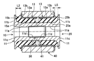
第1防振ブッシュ10は、図2に示すように、筒状部11a及び外向きフランジ部11bを有する内筒金具11と、筒状部13a及び外向きフランジ部13bを有する外筒金具13と、ゴム本体部15a及びゴムフランジ部15bを有するゴム弾性体15とから構成されている。内筒金具11は、厚肉円筒形状の筒状部11aと、筒状部11aの軸方向一端から径方向外方に延出するリング状の外向きフランジ部11bとからなる。また、外筒金具13は、同様に、円筒形状の筒状部13aと、筒状部13aの軸方向一端から径方向外方に延出するリング状の外向きフランジ部13bとからなり、内筒金具11よりも薄肉に形成されている。この外筒金具13は、その筒状部13aが内筒金具11の筒状部11aよりも所定寸法大径で且つ軸方向長さが短くされており、内筒金具11の外周側に所定距離を隔てて同軸状に配設されている。
As shown in FIG. 2, the first
そして、内筒金具11の外向きフランジ部11bと外筒金具13の外向きフランジ部13bは、軸方向の同じ側に位置するようにされているとともに、外筒金具13が内筒金具11に対して外向きフランジ部11bとは反対の軸方向端部側へ寄った状態に配設されており、外筒金具13の外向きフランジ部13bが形成されていない側の軸方向端部が、内筒金具11の外向きフランジ部11bが形成されていない側の軸方向端面よりも、所定距離:L1だけ軸方向外方へ突出している。
The
なお、外筒金具13の外向きフランジ部13bは、内筒金具11の筒状部11aの外径寸法よりも大きく且つ内筒金具11の外向きフランジ部11bの外径寸法よりも小さい内径寸法と、内筒金具11の外向きフランジ部11bの外径寸法よりも大きい外径寸法をもって形成されている。また、内筒金具11の外向きフランジ部11bの軸方向内側面は、径方向内方に向かうに従って次第に外筒金具13側に接近する略円弧形状の湾曲断面とされている。また、内筒金具11の外向きフランジ部11b側の軸方向端面は、中央部分11cが環状にセレーション加工及び焼入加工されて、取付相手部材(取付部材50の対向固定板51、51)に対する圧着固定面とされている。また、内筒金具11の内孔は、外向きフランジ部11bと反対側の軸方向端部が軸方向に所定長さに亘って大径化されており、この大径化された部分によって連結筒部材30が圧入固定される連結固定部11dが形成されている。
The
ここで用いられている連結筒部材30は、鉄系金属により各外筒金具13、23と略同じ肉厚の円筒形状に形成されており、各内筒金具11、21の軸方向長さの約1/2の軸方向長さを有し、各内筒金具11、21の内孔に設けられた連結固定部11d、21dの直径よりも僅かに大きい外径を有する。この連結筒部材30は、防振ブッシュ組付体が車体(図示せず)に組み付けられる前には、図2に示すように、一方の第1防振ブッシュ10の内筒金具11の内孔に設けられた連結固定部11d内に軸方向一方側の半分が挿入された状態で圧入固定されている。
The connecting
ゴム弾性体15は、上記のように径方向に離間配置された内筒金具11と外筒金具13の間に介装されている。このゴム弾性体15は、内筒金具11及び外筒金具13とともに一体加硫成形することにより形成されており、内筒金具11における筒状部11aの外周面と外向きフランジ部11bの軸方向内面、及び外筒金具13における筒状部13aの内周面と外向きフランジ部13bの軸方向外面に、それぞれ加硫接着されている。このゴム弾性体15は、全体として厚肉の略円筒形状に形成されており、内外筒金具11、13間において、各筒状部11a、13aの径方向対向面間を連結するゴム本体部15aと、各外向きフランジ部11b、13bの軸方向対向面間を連結するゴムフランジ部15bとを有する。
The rubber
なお、ゴム弾性体15の加硫成形後には、外筒金具13の筒状部13aに対して八方絞り加工等による縮径が施されており、これによりゴム弾性体15の引張応力が解消され、ゴム本体部15aに対して径方向の所定量の予圧縮が加えられている。ゴム本体部15aのゴムフランジ部15bと反対側の軸方向端面は、径方向外方側の部分が僅かに窪んだ湾曲面15cとされている。
Note that after the rubber
一方、ゴムフランジ部15bは、内外筒金具11、13の各外向きフランジ部11b、13bの軸方向対向面間の略全体に亘って配設されており、内筒金具11の外向きフランジ部11b側端部よりも外筒金具13の外向きフランジ部13b側端部の方が僅かに大径とされている。即ち、ゴムフランジ部15bの外周面における外筒金具13の外向きフランジ部13b側端部は、軸方向断面において略平坦となるように形成され、ゴムフランジ部15bの外周面における内筒金具11の外向きフランジ部11b側には、径方向内方へ湾曲状に凹んで周方向に連続して延びる凹部15dが形成されている。このゴムフランジ部15bの軸方向のばね定数は、ゴムフランジ部15bの最小外径となる凹部15dの最深底部間の寸法と、ゴムフランジ部15bの軸方向長さ:L2に基づいて設定される。なお、このゴムフランジ部15bの軸方向長さ:L2は、第2防振ブッシュ20のゴムフランジ部25bの軸方向長さL5よりも長くされている。
On the other hand, the
第2防振ブッシュ20は、図2に示すように、筒状部11a及び外向きフランジ部11bを有する内筒金具11と、筒状部13a及び外向きフランジ部13bを有する外筒金具13と、ゴム本体部25a及びゴムフランジ部25bを有するゴム弾性体25とから構成されている。この第2防振ブッシュ20は、第1防振ブッシュ10と同一の内筒金具11及び外筒金具13を用いて、ゴム弾性体25をそれら内外筒金具11、13と一体加硫成形することにより形成されたものであり、第2防振ブッシュ20のゴム弾性体25の形状のみが第1防振ブッシュ10のゴム弾性体15と異なるものである。よって、第1防振ブッシュ10の内筒金具11及び外筒金具13と共通する部材やそれらの部位等については、図中に同じ番号を付すのみに止めて詳しい説明は省略し、以下、ゴム弾性体25に関する異なる点を中心に説明する。
As shown in FIG. 2, the second
ゴム本体部25aのゴムフランジ部25bと反対側の軸方向端面は、内筒金具11の筒状部11a側端部よりも外筒金具13の筒状部13a側端部の方が軸方向内方へ少し寄った所に位置しており、それらの径方向における両端部間には、断面が略円弧状となるよう軸方向内方へ凹んだ凹部25cが周方向に連続して形成されている。一方、ゴムフランジ部25bの軸方向長さ:L5は、第1防振ブッシュ10のゴムフランジ部15bの軸方向長さ:L2よりも短くされている。これに伴い、外筒金具13の外向きフランジ部13bは、内筒金具11の外向きフランジ部11bに接近したところに位置しており、外筒金具13の外向きフランジ部13bが形成されていない側の軸方向端面は、内筒金具11の外向きフランジ部11bが形成されていない側の軸方向端面よりも、所定距離:L4だけ軸方向内方へ寄った所に位置している。
The axial end surface on the opposite side of the
そして、ゴムフランジ部25bの外周面は、内筒金具11の外向きフランジ部11b側端部よりも外筒金具13の外向きフランジ部13b側端部の方が僅かに大径とされている。ゴムフランジ部25bの外周面の軸方向両端部間には、断面が略円弧状となるよう径方向内方へ凹んだ凹部25dが周方向に連続して延びるように形成されている。この凹部25dの最深底部は、第1防振ブッシュ10のゴムフランジ部15bに形成された凹部15dの最深底部と略同じにされている。このゴムフランジ部25bの軸方向のばね定数は、ゴムフランジ部25bの最小外径となる凹部25dの最深底部間の寸法と、ゴムフランジ部25bの軸方向長さ:L5に基づいて設定される。
The outer peripheral surface of the
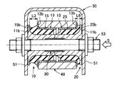
上記のように構成された第1防振ブッシュ10と第2防振ブッシュ20は、図1に示すように、アームアイ40の装着孔41に対して、軸方向両側の開口部からそれぞれ圧入されており、各内筒金具11、11の外向きフランジ部11b、11bと反対側の端面どうしが当接し、且つ各外筒金具13、13の外向きフランジ部13b、13bの軸方向内面がアームアイ40の軸方向端面と当接した状態になるまで圧入される。このとき、第1防振ブッシュ10の内筒金具11の連結固定部11dに軸方向一方側の半分が挿入された状態で圧入固定されている連結筒部材30の軸方向他方側が、第2防振ブッシュ20の内筒金具11の連結固定部11dに圧入される。これにより、両内筒金具11、11は、各内筒金具11、11の外向きフランジ部11b、11bと反対側の端面どうしが当接した状態で連結固定される。
As shown in FIG. 1, the first
このようにして、両内筒金具11、11が連結筒部材30により連結固定されると、第1防振ブッシュ10の内外筒金具11、13の両外向きフランジ部11b、13bどうし、及び第2防振ブッシュ20の内外筒金具11、13の両外向きフランジ部11b、13bどうしは、それぞれ軸方向において互いに接近するように相対変位する。これにより、第1防振ブッシュ10の内外筒金具11、13の両外向きフランジ部11b、13b間を連結しているゴムフランジ部15bと、第2防振ブッシュ20の内外筒金具11、13の両外向きフランジ部11b、13b間を連結しているゴムフランジ部25bは、それぞれの両外向きフランジ部11b、13bの軸方向の相対変位量に応じて軸方向に圧縮され、両ゴムフランジ部15b、25bにそれぞれ異なる量の予圧縮が付与される。この場合、第1防振ブッシュ10のゴムフランジ部15bは、第2防振ブッシュ20のゴムフランジ部25bよりも大きく圧縮され、ゴムフランジ部25bよりも大きな予圧縮が付与されている。
In this way, when both the inner
なお、上記のように組み付けられた防振ブッシュ組付体においては、図1に示す組付状態下において、第1防振ブッシュ10のゴムフランジ部15bの軸方向長さ:L3は、付与された予圧縮量に応じて、無負荷状態時の軸方向長さ:L2(図2参照。)より所定長さ短くなり、第2防振ブッシュ20のゴムフランジ部25bの軸方向長さ:L6は、付与された予圧縮量に応じて、無負荷状態時の軸方向長さ:L5(図2参照。)より所定長さ短くなっている。
In the vibration isolating bush assembly assembled as described above, the axial length L3 of the
以上のように構成された本実施形態の防振ブッシュ組立体は、図3に示すように、車体(図示せず)に固設された取付部材50の一対の対向固定板51、51間に嵌め込まれて、第1及び第2防振ブッシュ10、20が直列状に配列された状態に配設される。そして、一対の対向固定板51、51に設けられた貫通孔に挿通されて、それら一対の対向固定板51、51間に跨って配設された支持ボルト53が、第1及び第2防振ブッシュ10、20の両内筒金具11、11の内孔に嵌挿されることによって、防振ブッシュ組立体が、支持ボルト53を介して、一対の対向固定板51、51に対して軸支される。
As shown in FIG. 3, the vibration isolating bush assembly of the present embodiment configured as described above is provided between a pair of opposed fixing
そして、一対の対向固定板51、51並びに第1及び第2防振ブッシュ10、20に挿通された支持ボルト53がナット54で締め付けられて、一対の対向固定板51、51が相互に接近する方向に変形することにより、軸方向に連結一体化された両内筒金具11、11に対して軸方向の締付力が及ぼされる。この締付力により、両内筒金具11、11の軸方向外面に施されたセレーション加工部が、各対向固定板51、51の当接面に対して圧着される。このようにして、本実施形態の防振ブッシュ組立体が、車体側に固設された取付部材50の一対の対向固定板51、51に対して、支持ボルト53を介して軸支されるように取り付けられることにより、サスペンションアームが車体に対して揺動可能に防振連結される。
Then, the
ところで、本実施形態の防振ブッシュ組立体は、上記のように取り付けられた際に、図4に示すように、支持ボルト53に対して軸方向の初期加重Sが入力する箇所に設置されている。そのため、初期加重Sの入力により、両内筒金具11、11と両外筒金具13、13が軸方向に相対変位することとなる。これにより、初期荷重Sの入力側に位置する第2防振ブッシュ20においては、内筒金具11と外筒金具13の両外向きフランジ部11b、13bが軸方向において互いに接近するように相対変位するため、両外向きフランジ部11b、13b間を連結するゴムフランジ部25bには軸方向の圧縮荷重が入力し、ゴムフランジ部25bに付与されていた予圧縮が増加した状態となる。
By the way, the anti-vibration bushing assembly of the present embodiment is installed at a place where an axial initial load S is input to the
一方、初期荷重Sの入力側と反対側に位置する第1防振ブッシュ10においては、内筒金具11と外筒金具13の両外向きフランジ部11b、13bが軸方向において互いに離間するように相対変位するため、両外向きフランジ部11b、13b間を連結するゴムフランジ部15bには軸方向の引張荷重が入力し、ゴムフランジ部15bに付与されていた予圧縮が減少する。しかし、このゴムフランジ部15bには、初期荷重Sの入力による引張荷重よりも大きな予圧縮が付与されているため、初期荷重Sが入力した後でも、相殺されて残った量の予圧縮が残存している。これにより、ゴムフランジ部15bに入力する軸方向や捩じり方向の引張荷重に対する耐久性が確保される。
On the other hand, in the first
以上のようにして、自動車に取り付けられた本実施形態の防振ブッシュ組立体は、軸方向の初期荷重Sが入力された際に、引張荷重が入力する側に配置された第1防振ブッシュ10のゴムフランジ部15bが、第2防振ブッシュ20のゴムフランジ部25bよりも軸方向長さが長くされている。これにより、そのゴムフランジ部15bは、軸方向及び捩じり方向における自由長がより長くなるようにされているため、軸方向や捩じり方向の荷重が入力された際に生じる歪みが有効に低減されるようになり、耐久性を向上させることができる。
As described above, the vibration isolating bushing assembly of the present embodiment attached to the automobile has the first vibration isolating bushing disposed on the side where the tensile load is input when the axial initial load S is input. The ten
また、第1防振ブッシュ10のゴムフランジ部15bは、防振ブッシュ組立体として組み付けられたときに、第2防振ブッシュ20のゴムフランジ部25bよりも大きい予圧縮が付与されているため、防振ブッシュ組立体が自動車に取り付けられた際に、軸方向の初期荷重Sが入力されても、有効に予圧縮が付与された状態を維持することができる。これにより、ゴムフランジ部15bの軸方向長さが長くされていることと相俟って、軸方向や捩じり方向の荷重が入力された際に生じる歪みが有効に低減されるようになり、耐久性の向上が可能となる。
Further, when the
以上のように、本実施形態の防振ブッシュ組立体によれば、第1防振ブッシュ10のゴムフランジ部15bは、第2防振ブッシュ20のゴムフランジ部25bよりも軸方向長さが長くされているとともに、各内筒金具11、11の外向きフランジ部11bと反対側の端面どうしが当接した状態のときに、一方のゴムフランジ部15bに他方のゴムフランジ部25bよりも大きな予圧縮が付与されるようにして、両ゴムフランジ部15b、25bに異なる量の予圧縮が付与されるように構成されているため、軸方向の初期荷重Sが入力された際に、ゴムフランジ部15bに対して引張荷重が入力する側に配置される第1防振ブッシュ10の耐久性を向上させることができる。
As described above, according to the vibration isolating bush assembly of the present embodiment, the
また、本実施形態の防振ブッシュ組立体は、第1防振ブッシュ10と第2防振ブッシュ20の内筒金具11、11及び外筒金具13、13が、同一のものが用いられているため、それぞれ1種類のものを準備すればよく、製造コストを低減化することができる。
In the vibration isolating bush assembly of the present embodiment, the same inner
10…第1防振ブッシュ 11…内筒金具(内筒部材) 11a…筒状部 11b…外向きフランジ部 13…外筒金具(外筒部材) 13a…筒状部 13b…外向きフランジ部 15…ゴム弾性体 15a…ゴム本体部 15b…ゴムフランジ部 20…第2防振ブッシュ 25…ゴム弾性体 25a…ゴム本体部 25b…ゴムフランジ部 30…連結筒部材 40…アームアイ(取付筒部材) 41…装着孔 50…取付部材 51…対向固定板 53…支持ボルト
DESCRIPTION OF
Claims (5)
一方の前記ゴムフランジ部は、他方の前記ゴムフランジ部よりも軸方向長さが長くされているとともに、各前記内筒部材の前記外向きフランジ部と反対側の端面どうしが当接した状態のときに、一方の前記ゴムフランジ部と他方の前記ゴムフランジ部に異なる量の予圧縮が付与されるように構成されていることを特徴とする防振ブッシュ組立体。 An inner cylinder member having an outward flange portion at one end in the axial direction, and an outer cylinder member having an outward flange portion at one end in the axial direction and coaxially disposed on the outer peripheral side of the inner cylinder member; A rubber main body portion that connects between the radially opposed surfaces of the inner cylinder member and the outer cylinder member and a rubber flange portion that connects between the axially opposed surfaces of the outward flange portions, and elastically connects the two members. The two end surfaces of the inner cylinder member and the outer cylinder member on the opposite side to the outward flange portion from both sides in the axial direction are installed in the mounting hole of the mounting cylinder member by using two anti-vibration bushes made of rubber elastic bodies. In the anti-vibration bush assembly assembled in a state where both the outer cylindrical members are fitted in the mounting holes by inserting the outer cylindrical members so as to face each other,
One of the rubber flange portions has an axial length longer than that of the other rubber flange portion, and the end surfaces on the opposite side of the outward flange portions of the inner cylindrical members are in contact with each other. Sometimes, the anti-vibration bushing assembly is configured such that different amounts of pre-compression are applied to one of the rubber flange portions and the other rubber flange portion.
Priority Applications (1)
| Application Number | Priority Date | Filing Date | Title |
|---|---|---|---|
| JP2006085660A JP2007263154A (en) | 2006-03-27 | 2006-03-27 | Vibration absorbing bush assembly |
Applications Claiming Priority (1)
| Application Number | Priority Date | Filing Date | Title |
|---|---|---|---|
| JP2006085660A JP2007263154A (en) | 2006-03-27 | 2006-03-27 | Vibration absorbing bush assembly |
Publications (1)
| Publication Number | Publication Date |
|---|---|
| JP2007263154A true JP2007263154A (en) | 2007-10-11 |
Family
ID=38636358
Family Applications (1)
| Application Number | Title | Priority Date | Filing Date |
|---|---|---|---|
| JP2006085660A Withdrawn JP2007263154A (en) | 2006-03-27 | 2006-03-27 | Vibration absorbing bush assembly |
Country Status (1)
| Country | Link |
|---|---|
| JP (1) | JP2007263154A (en) |
Cited By (4)
| Publication number | Priority date | Publication date | Assignee | Title |
|---|---|---|---|---|
| JP2015132282A (en) * | 2014-01-09 | 2015-07-23 | 住友理工株式会社 | Cylindrical vibration-proofing device |
| CN109778604A (en) * | 2019-03-07 | 2019-05-21 | 安徽神剑科技股份有限公司 | A kind of bilayer nonlinear vibration reduction fastener lasso |
| US10611404B2 (en) | 2015-10-22 | 2020-04-07 | Jtekt Corporation | Damper device and steering device |
| CN113788040A (en) * | 2021-09-30 | 2021-12-14 | 株洲时代瑞唯减振装备有限公司 | Pre-compression amount adjusting method for rotating arm node |
-
2006
- 2006-03-27 JP JP2006085660A patent/JP2007263154A/en not_active Withdrawn
Cited By (5)
| Publication number | Priority date | Publication date | Assignee | Title |
|---|---|---|---|---|
| JP2015132282A (en) * | 2014-01-09 | 2015-07-23 | 住友理工株式会社 | Cylindrical vibration-proofing device |
| US10611404B2 (en) | 2015-10-22 | 2020-04-07 | Jtekt Corporation | Damper device and steering device |
| CN109778604A (en) * | 2019-03-07 | 2019-05-21 | 安徽神剑科技股份有限公司 | A kind of bilayer nonlinear vibration reduction fastener lasso |
| CN109778604B (en) * | 2019-03-07 | 2024-03-08 | 安徽神剑科技股份有限公司 | Ferrule for double-layer nonlinear vibration reduction fastener |
| CN113788040A (en) * | 2021-09-30 | 2021-12-14 | 株洲时代瑞唯减振装备有限公司 | Pre-compression amount adjusting method for rotating arm node |
Similar Documents
| Publication | Publication Date | Title |
|---|---|---|
| US6666438B2 (en) | Cylindrical elastic mount | |
| JP4356641B2 (en) | Torque rod | |
| US10451133B2 (en) | Tubular vibration-damping device | |
| WO2017056546A1 (en) | Bracketed cylindrical vibration isolator | |
| JP2006242289A (en) | Vibration-proofing bush | |
| JP2003294084A (en) | Vibration-resistant bush | |
| JP2007263154A (en) | Vibration absorbing bush assembly | |
| JP3858144B2 (en) | Vibration isolator | |
| JP3712818B2 (en) | Anti-vibration bushing and bushing assembly | |
| JP3729404B2 (en) | Anti-vibration bush | |
| JP2000193003A (en) | Engine roll mount for automobile | |
| JP3729003B2 (en) | Anti-vibration bush and anti-vibration bush assembly | |
| JP2014145410A (en) | Suspension bush | |
| JP4358874B2 (en) | Anti-vibration bush | |
| JP2002248923A (en) | Stabilizer bar with vibration control bush | |
| WO2018198412A1 (en) | Torque rod | |
| WO2012132105A1 (en) | Vibration prevention device | |
| JP2006347370A (en) | Suspension bush | |
| JPH08270698A (en) | Vibration insulation bush | |
| JP4303297B2 (en) | Anti-vibration bush | |
| JP2019052725A (en) | Torque rod | |
| JP2010060023A (en) | Vibration damping bushing | |
| JP2001248671A (en) | Bush | |
| JP7121719B2 (en) | Cylindrical anti-vibration device with bracket | |
| JP5396252B2 (en) | Cylindrical vibration isolator |
Legal Events
| Date | Code | Title | Description |
|---|---|---|---|
| A621 | Written request for application examination |
Free format text: JAPANESE INTERMEDIATE CODE: A621 Effective date: 20080820 |
|
| A761 | Written withdrawal of application |
Free format text: JAPANESE INTERMEDIATE CODE: A761 Effective date: 20090428 |